safety risk mitigation - tools
TRANSCRIPT
Safety Risk Mitigation (SRM) - Tools
Agenda 1. Definition 2. SMS and SSP expectation 3. Capability and Competency 4. Related terminologies 5. Protocol 6. Tools – Excel / BowTie 7. Discussion/ Q&A
2
1. SRM Definition
A systematic process to account for the availability and adequacy of defences pertaining to a given combination (s) of related Hazard, Top Event and Consequence.
Safety Risk Mitigation (SRM) is also known as: Safety Assessment (SA) Safety Risk Assessment (SRA) Safety Risk Management (SRM) Hazard Identification & Risk Assessment (HIRA) Hazard Identification & Risk Mitigation (HIRM), etc
3
2. SMS and SSP SRM expectation (Annex 19)
SMS: Hazard Identification (SMS element 2.1)
Safety risk assessment and mitigation (SMS element 2.2)
SSP: State safety risk management (SSP component number 2 )
Each State shall develop and maintain a process that ensures the identification and analysis of hazards and the assessment of safety risks associated with those hazards (SMP’s proposed A19 SARP, Nov 2014)
4
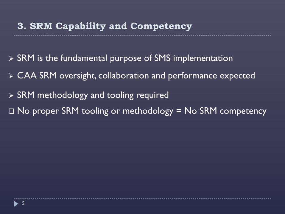
3. SRM Capability and Competency
SRM is the fundamental purpose of SMS implementation
CAA SRM oversight, collaboration and performance expected
SRM methodology and tooling required
No proper SRM tooling or methodology = No SRM competency
5
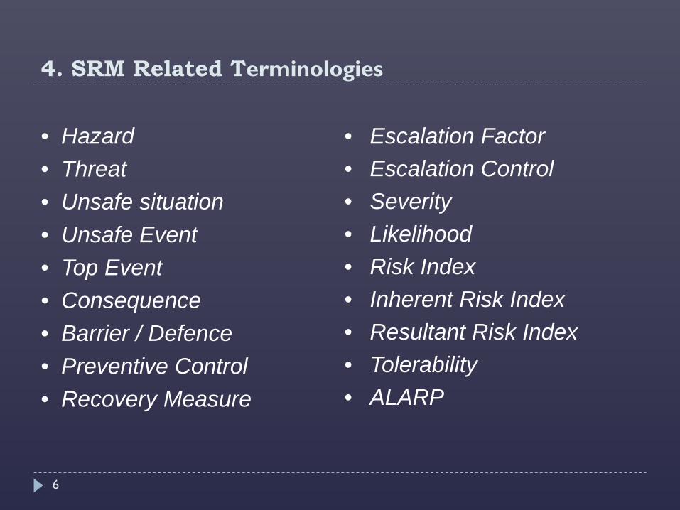
4. SRM Related Terminologies
• Hazard • Threat • Unsafe situation • Unsafe Event • Top Event • Consequence • Barrier / Defence • Preventive Control • Recovery Measure
• Escalation Factor • Escalation Control • Severity • Likelihood • Risk Index • Inherent Risk Index • Resultant Risk Index • Tolerability • ALARP
6
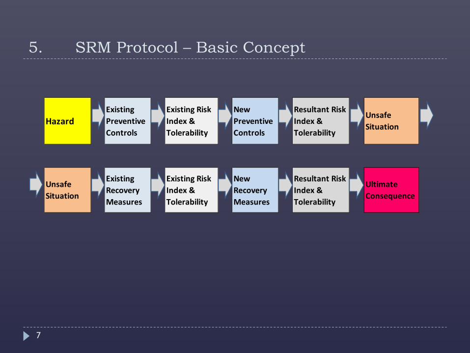
5. SRM Protocol – Basic Concept
Hazard
Existing Preventive Controls
Unsafe Situation
Existing Risk Index & Tolerability
New Preventive Controls
Resultant Risk Index & Tolerability
Unsafe Situation
Existing Recovery Measures
Ultimate Consequence
Existing Risk Index & Tolerability
Resultant Risk Index & Tolerability
New Recovery Measures
7
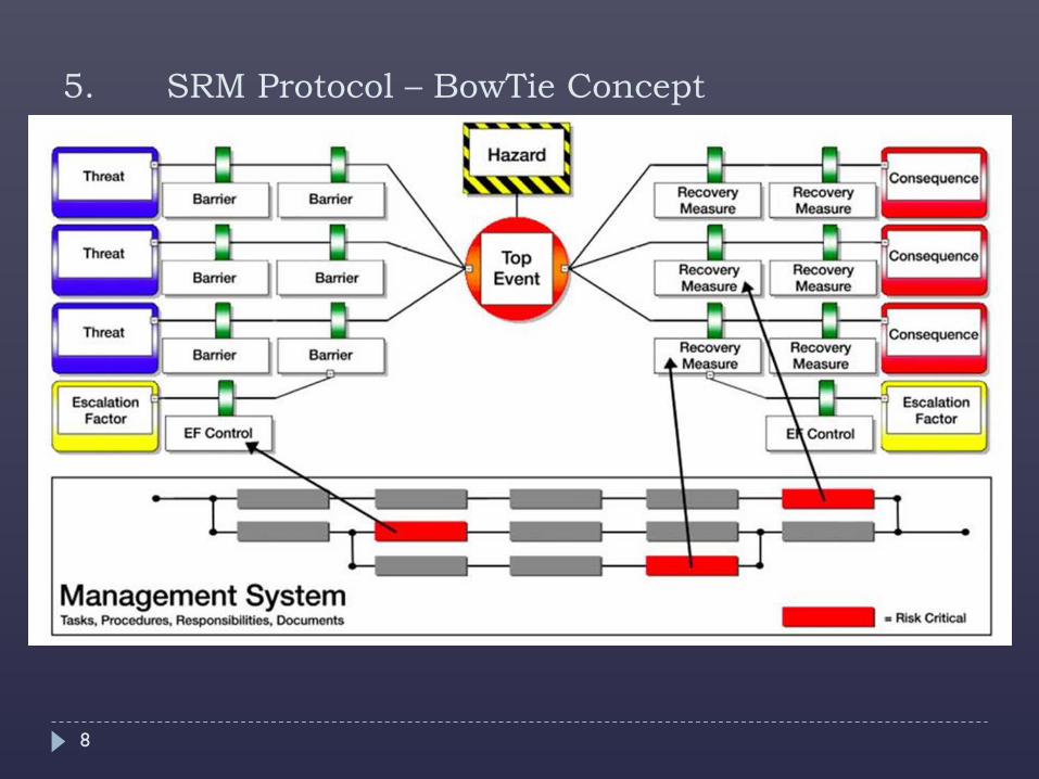
5. SRM Protocol – BowTie Concept
8
6. SRM Tools
Excel template (Doc 9859, C2-App2)
Software (Bow-Tie)
9
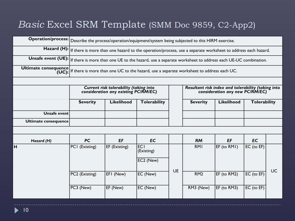
Basic Excel SRM Template (SMM Doc 9859, C2-App2) Operation/process: Describe the process/operation/equipment/system being subjected to this HIRM exercise.
Hazard (H): If there is more than one hazard to the operation/process, use a separate worksheet to address each hazard.
Unsafe event (UE): If there is more than one UE to the hazard, use a separate worksheet to address each UE-UC combination.
Ultimate consequence (UC): If there is more than one UC to the hazard, use a separate worksheet to address each UC.
Current risk tolerability (taking into consideration any existing PC/RM/EC)
Resultant risk index and tolerability (taking into consideration any new PC/RM/EC)
Severity Likelihood Tolerability Severity Likelihood Tolerability
Unsafe event
Ultimate consequence
Hazard (H) PC EF EC RM EF EC
H PC1 (Existing) EF (Existing) EC1 (Existing)
UE
RM1 EF (to RM1) EC (to EF)
UC
EC2 (New)
PC2 (Existing) EF1 (New) EC (New) RM2 EF (to RM2) EC (to EF)
PC3 (New) EF (New) EC (New) RM3 (New) EF (to RM3) EC (to EF)
10
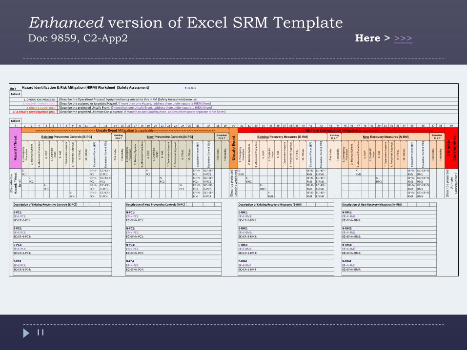
Enhanced version of Excel SRM Template Doc 9859, C2-App2 Here > >>>
Hazard Identification & Risk Mitigation (HIRM) Worksheet [Safety Assessment] 9 Feb 2015
2 3 4 5 6 7 8 9 10 11 12 13 14 15 16 17 18 19 20 21 22 23 24 25 26 27 28 29 30 31 32 33 34 35 36 37 38 39 40 41 42 43 44 45 46 47 48 49 50 51 52 53 54 55 56 57 58 59
1. E
mer
genc
yP
roce
dure
2. B
acku
p S
yste
m
3. A
bnor
mal
Pro
cedu
re
4. S
OP
5. D
uplic
ate
Insp
n
6. G
M
7. O
rgan
izat
ion
App
rova
l
8. P
erso
nnel
App
rova
l
9. T
RN
G
10. O
ther
s
Esc
alat
ion
Fact
or [E
F]
Esc
alat
ion
Con
trol [
EC
]
Ris
k In
dex
Tole
rabi
lity
1. E
mer
genc
yP
roce
dure
2. B
acku
p S
yste
m
3. A
bnor
mal
Pro
cedu
re
4. S
OP
5. D
uplic
ate
Insp
n
6. G
M
7. O
rgan
izat
ion
App
rova
l
8. P
erso
nnel
App
rova
l
9. T
RN
G
10. O
ther
s
Esc
alat
ion
Fact
or [E
F]
Esc
alat
ion
Con
trol [
EC
]
Ris
k In
dex
Tole
rabi
lity
1. E
mer
genc
yP
roce
dure
2. B
acku
p S
yste
m
3. A
bnor
mal
Pro
cedu
re
4. S
OP
5. D
uplic
ate
Insp
n
6. G
M
7. O
rgan
izat
ion
App
rova
l
8. P
erso
nnel
App
rova
l
9. T
RN
G
10. O
ther
s
Esc
alat
ion
Fact
or [E
F]
Esc
alat
ion
Con
trol [
EC
]
Ris
k In
dex
Tole
rabi
lity
1. E
mer
genc
yP
roce
dure
2. B
acku
p S
yste
m
3. A
bnor
mal
Pro
cedu
re
4. S
OP
5. D
uplic
ate
Insp
n
6. G
M
7. O
rgan
izat
ion
App
rova
l
8. P
erso
nnel
App
rova
l
9. T
RN
G
10. O
ther
s
Esc
alat
ion
Fact
or [E
F]
Esc
alat
ion
Con
trol [
EC
]
Ris
k In
dex
Tole
rabi
lity
E-PC1
EF>E-PC1
EC>EF>E-PC1
N-PC1
EF>N-PC1
EC>EF>N-PC1
E-RM1
EF>E-RM1
EC>EF>E-RM1
N-RM1
EF>N-RM1
EC>EF>N-RM1
E-PC2
EF>E-PC2
EC>EF-F-PC2
N-PC2
EF>N-PC2
EC>EF>N-PC2
E-RM2
EF>E-RM2
EC>EF>E-RM2
N-RM2
EF>N-RM2
EC>EF>N-RM2
E-PC3
EF>E-PC3
EC>EF>E-PC3
N-PC3
EF>N-PC3
EC>EF>N-PC3
E-RM3
EF>E-RM3
EC>EF>E-RM3
EF>N-RM3
EC>EF>N-RM3
E-PC4
EF>E-PC4
EC>EF>E-PC4
EF>N-PC4
EC>EF>N-PC4
E-RM4
EF>E-RM4
EC>EF>E-RM4
EF>N-RM4
EC>EF>N-RM4
Description of Existing Preventive Controls [E-PC] Description of New Preventive Controls [N-PC] Description of Existing Recovery Measures [E-RM] Description of New Recovery Measures [N-RM]
E-RM2:EF>E-RM2: EC>EF>E-RM2:
E-RM3:EF>E-RM3:EC>EF>E-RM3:
E-RM4EF>E-RM4EC>EF>E-RM4
EF>N-RM1:EC>EF>N-RM1:
EF>N-RM4:EC>EF>N-RM4:
EC>EF>N-RM2:
N-RM3:EF>N-RM3:EC>EF>N-RM3:
N-RM4:EF>E-PC4:EC>EF>E-PC4:
N-PC2:
EC>EF>N-PC2:
N-PC3:EF>N-PC3:EC>EF>N-PC3:
N-PC4:EF>N-PC4:EC>EF>N-PC4:
EC>EF>E-PC2:
E-PC3:EF>E-PC3:EC>EF>E-PC3:
E-PC4:
E-PC2:EF>E-PC2:
N-RM2:EF>N-RM2:
EC>EF>N-PC1:
E-RM1: EF>E-RM1:EC>EF>E-RM1:
E-PC1: EF>E-PC1:EC>EF>E-PC1:
EF>N-PC2: U
nsaf
e Ev
entExisting
RI & T
N-PC1: EF>N-PC1:
N-RM1:
Table A
1. OPERATION/ PROCESS: 2. HAZARD / THREAT [H/T]:
3. UNSAFE EVENT [UE]: 4. ULTIMATE CONSEQUENCE [UC]:
Table B1
Haz
ard
/ Thr
eat
[Des
crib
e th
e H
azar
d/ T
Hre
at
here
]
>>>>>>>>>>>>>>>>>>>>>>>>>>>>>>>>>>>> Unsafe Event Mitigation (as applicable) >>>>>>>>>>>>>>>>>>>>>>>>>>>>>>>>>>>>
Sht 4
New Preventive Controls [N-PC] New Recovery Measures [N-RM] Existing Recovery Measures [E-RM]
[Describe the Operation/ Process/ Equipment being subject to this HIRM (Safety Assessment) exercise] [Describe the assigned or targetted Hazard. If more than one Hazard, address them under separate HIRM Sheet] [Describe the projected Unsafe Event. If more than one Unsafe Event, address them under separate HIRM Sheet] [Describe the projected Ultimate Consequence. If more than one Consequence, address them under separate HIRM Sheet]
Existing RI & T
Resultant RI & T
[Des
crib
e pr
ojec
ted
Ulti
mat
e Co
nseq
uenc
e /
[Des
crib
e pr
ojec
ted
Uns
afe
Even
t her
e]
Ulti
mat
e Co
nseq
uenc
eExisting Preventive Controls [E-PC] Resultant RI & T
>>>>>>>>>>>>>>>>>>>>>>>>>>>>>>>> Ultimate Consequence Mitigation (as applicable) >>>>>>>>>>>>>>>>>>>>>>>>>>>>>>>>
11
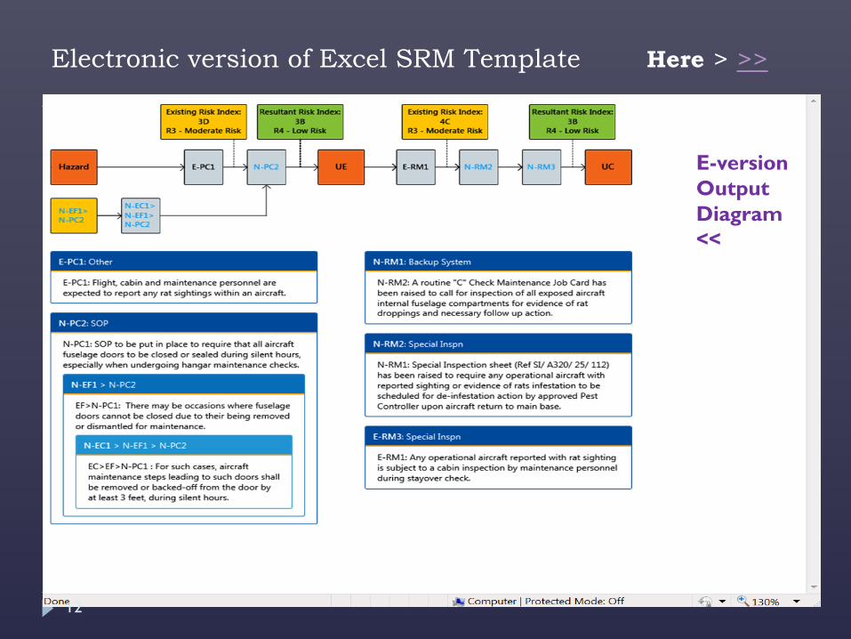
Electronic version of Excel SRM Template Here > >>
E-version Output Diagram <<
12
6. SRM Tools
BowTie SRM Software
13
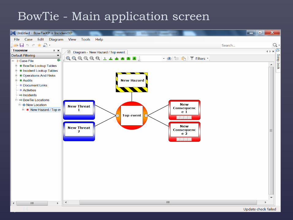
BowTie - Main application screen
14
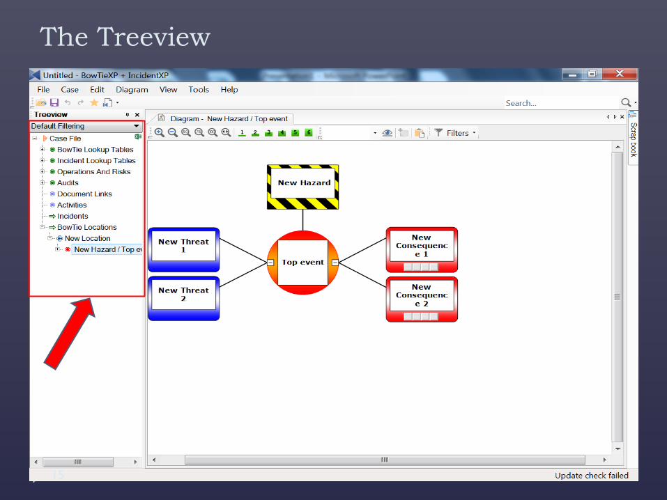
The Treeview
15
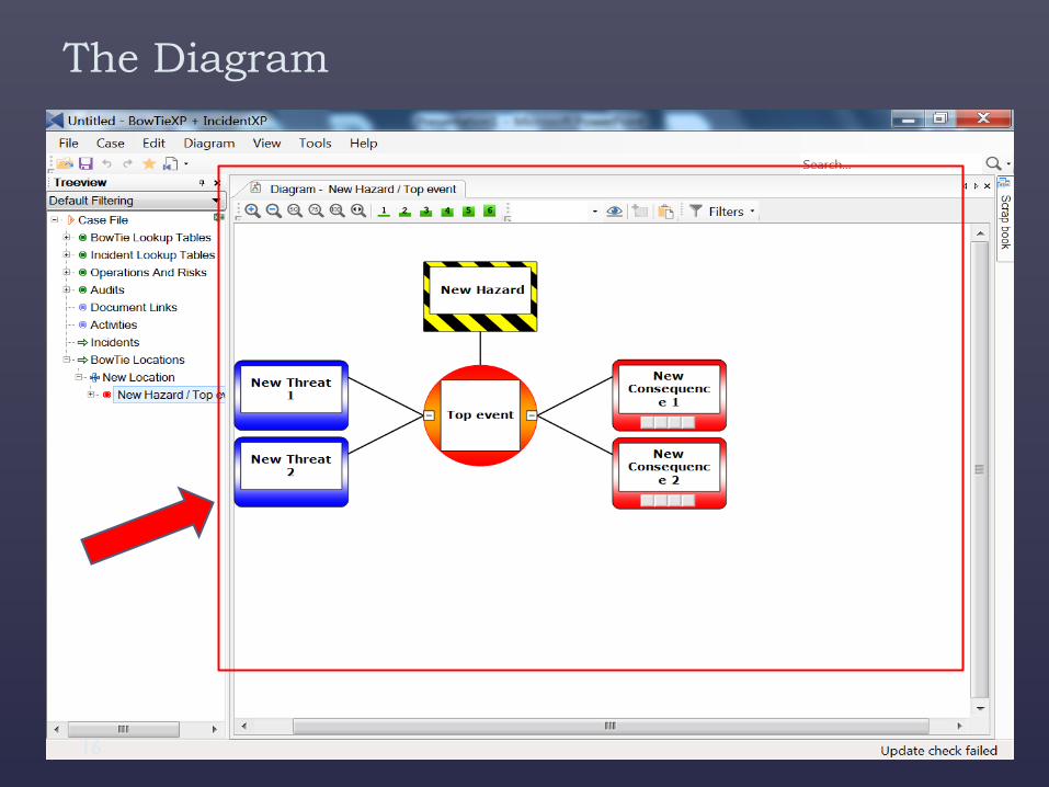
The Diagram
16
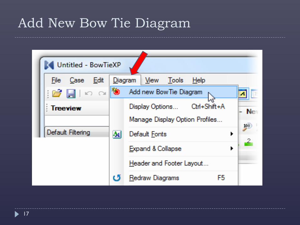
Add New Bow Tie Diagram
17
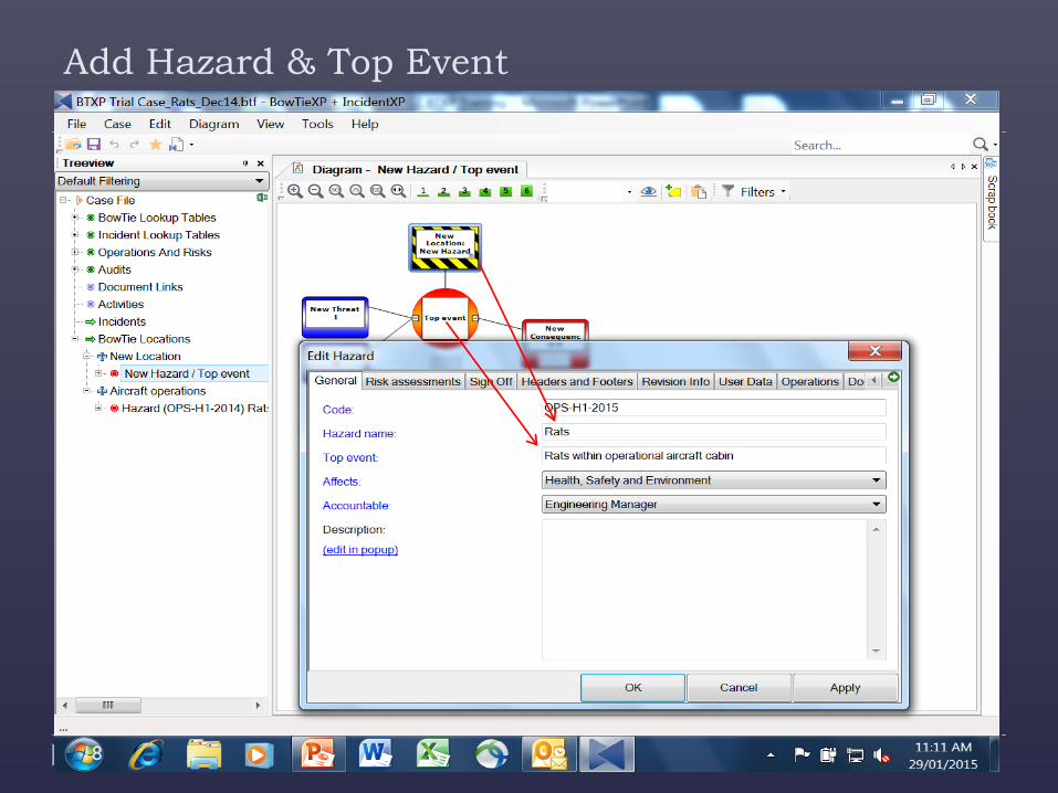
Add Hazard & Top Event
18
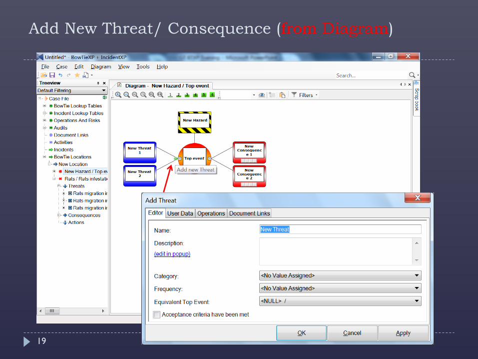
Add New Threat/ Consequence (from Diagram)
19
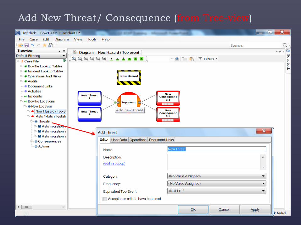
Add New Threat/ Consequence (from Tree-view)
20
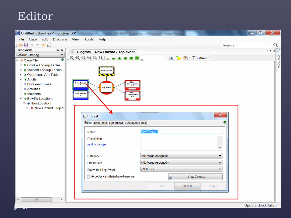
Editor
21
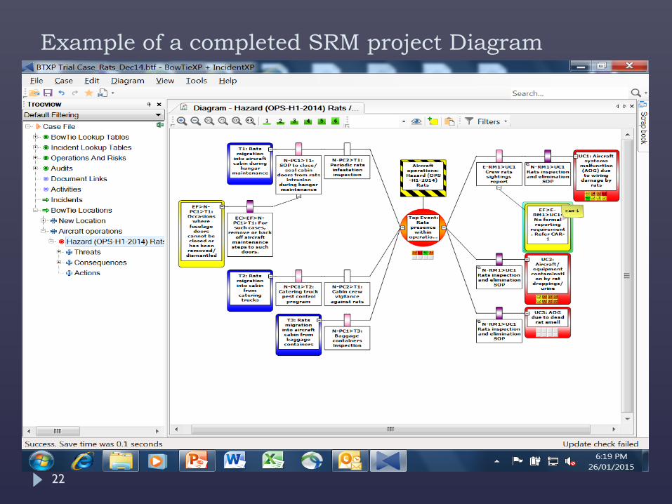
Example of a completed SRM project Diagram
22
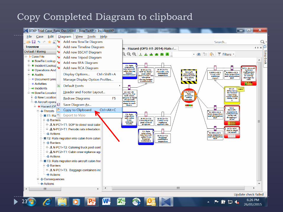
Copy Completed Diagram to clipboard
23
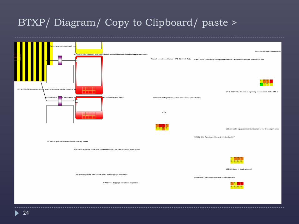
BTXP/ Diagram/ Copy to Clipboard/ paste >
Top Event: Rats presence within operational aircraft cabin
Aircraft operations: Hazard (OPS-H1-2014) Rats
N-PC2>T1: Periodic rats infestation inspectionN-PC1>T1: SOP to close/ seal cabin doors from rats intrusion during hangar maintenance
T1: Rats migration into aircraft cabin during hangar maintenance
EC>EF>N-PC1>T1: For such cases, remove or back off aircraft maintenance steps to such doors.
EF>N-PC1>T1: Occasions where fuselage doors cannot be closed or has been removed/ dismantled
N-PC2>T1: Cabin crew vigilance against ratsN-PC1>T2: Catering truck pest control program
T2: Rats migration into cabin from catering trucks
N-PC1>T3: Baggage containers inspection
T3: Rats migration into aircraft cabin from baggage containers
E-RM1>UC1 Crew rats sightings report N-RM1>UC1 Rats inspection and elimination SOP
UC1: Aircraft systems malfunctio
EF>E-RM1>UC1: No formal reporting requirement. Refer CAR-1
N-RM1>UC1 Rats inspection and elimination SOP
UC2: Aircraft/ equipment contamination by rat droppings/ urine
N-RM1>UC1 Rats inspection and elimination SOP
UC3: AOG due to dead rat smell
CAR-1
D2 E3 D4 D3
C1 C2 C3 C2
B3 C4 D2 E3
B0 C2 C1 C2
C2 D2 D3 D3
B1 B1 B1 B1
D2 B3 D4 E3
B2 B1 B3 C1
24
Quiz
25
Risk Index value is derived from the severity and likelihood of a Hazard.
TRUE / FALSE
FALSE Risk Index (Severity X Likelihood) pertains to a Top Event or Consequence
Quiz
26
The Likelihood of an Event or Consequence, should be correlated to the number of Barriers as well as their strength or quality
TRUE / FALSE
TRUE
In Summary
Safety Risk Mitigation is a key SMS-SSP process
Need to establish SMS-SSP SRM capability and competency
Use currently available SRM Tools (eg BowTie software, Excel template) or develop your own
27
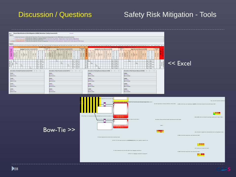
Discussion / Questions Safety Risk Mitigation - Tools
Top Event: Rats presence within operational aircraft cabin
Aircraft operations: Hazard (OPS-H1-2014) Rats
N-PC2>T1: Periodic rats infestation inspectionN-PC1>T1: SOP to close/ seal cabin doors from rats intrusion during hangar maintenance
T1: Rats migration into aircraft cabin during hangar maintenance
EC>EF>N-PC1>T1: For such cases, remove or back off aircraft maintenance steps to such doors.
EF>N-PC1>T1: Occasions where fuselage doors cannot be closed or has been removed/ dismantled
N-PC2>T1: Cabin crew vigilance against ratsN-PC1>T2: Catering truck pest control program
T2: Rats migration into cabin from catering trucks
N-PC1>T3: Baggage containers inspection
T3: Rats migration into aircraft cabin from baggage containers
E-RM1>UC1 Crew rats sightings report N-RM1>UC1 Rats inspection and elimination SOP
UC1: Aircraft systems malfunctio
EF>E-RM1>UC1: No formal reporting requirement. Refer CAR-1
N-RM1>UC1 Rats inspection and elimination SOP
UC2: Aircraft/ equipment contamination by rat droppings/ urine
N-RM1>UC1 Rats inspection and elimination SOP
UC3: AOG due to dead rat smell
CAR-1
D2 E3 D4 D3
C1 C2 C3 C2
B3 C4 D2 E3
B0 C2 C1 C2
C2 D2 D3 D3
B1 B1 B1 B1
D2 B3 D4 E3
B2 B1 B3 C1
Hazard Identification & Risk Mitigation (HIRM) Worksheet [Safety Assessment] 9 Feb 2015
2 3 4 5 6 7 8 9 10 11 12 13 14 15 16 17 18 19 20 21 22 23 24 25 26 27 28 29 30 31 32 33 34 35 36 37 38 39 40 41 42 43 44 45 46 47 48 49 50 51 52 53 54 55 56 57 58 59
1. E
mer
genc
yPr
oced
ure
2. B
acku
p Sy
stem
3. A
bnor
mal
Pro
cedu
re
4. S
OP
5. D
uplic
ate
Insp
n
6. G
M
7. O
rgan
izat
ion
Appr
oval
8. P
erso
nnel
App
rova
l
9. T
RN
G
10. O
ther
s
Esca
latio
n Fa
ctor
[EF]
Esca
latio
n C
ontro
l [EC
]
Ris
k In
dex
Tole
rabi
lity
1. E
mer
genc
yPr
oced
ure
2. B
acku
p Sy
stem
3. A
bnor
mal
Pro
cedu
re
4. S
OP
5. D
uplic
ate
Insp
n
6. G
M
7. O
rgan
izat
ion
Appr
oval
8. P
erso
nnel
App
rova
l
9. T
RN
G
10. O
ther
s
Esca
latio
n Fa
ctor
[EF]
Esca
latio
n C
ontro
l [EC
]
Ris
k In
dex
Tole
rabi
lity
1. E
mer
genc
yPr
oced
ure
2. B
acku
p Sy
stem
3. A
bnor
mal
Pro
cedu
re
4. S
OP
5. D
uplic
ate
Insp
n
6. G
M
7. O
rgan
izat
ion
Appr
oval
8. P
erso
nnel
App
rova
l
9. T
RN
G
10. O
ther
s
Esca
latio
n Fa
ctor
[EF]
Esca
latio
n C
ontro
l [EC
]
Ris
k In
dex
Tole
rabi
lity
1. E
mer
genc
yPr
oced
ure
2. B
acku
p Sy
stem
3. A
bnor
mal
Pro
cedu
re
4. S
OP
5. D
uplic
ate
Insp
n
6. G
M
7. O
rgan
izat
ion
Appr
oval
8. P
erso
nnel
App
rova
l
9. T
RN
G
10. O
ther
s
Esca
latio
n Fa
ctor
[EF]
Esca
latio
n C
ontro
l [EC
]
Ris
k In
dex
Tole
rabi
lity
E-PC1
EF>E-PC1
EC>EF>E-PC1
N-PC1
EF>N-PC1
EC>EF>N-PC1
E-RM1
EF>E-RM1
EC>EF>E-RM1
N-RM1
EF>N-RM1
EC>EF>N-RM1
E-PC2
EF>E-PC2
EC>EF-F-PC2
N-PC2
EF>N-PC2
EC>EF>N-PC2
E-RM2
EF>E-RM2
EC>EF>E-RM2
N-RM2
EF>N-RM2
EC>EF>N-RM2
E-PC3
EF>E-PC3
EC>EF>E-PC3
N-PC3
EF>N-PC3
EC>EF>N-PC3
E-RM3
EF>E-RM3
EC>EF>E-RM3
EF>N-RM3
EC>EF>N-RM3
E-PC4
EF>E-PC4
EC>EF>E-PC4
EF>N-PC4
EC>EF>N-PC4
E-RM4
EF>E-RM4
EC>EF>E-RM4
EF>N-RM4
EC>EF>N-RM4
Description of Existing Preventive Controls [E-PC] Description of New Preventive Controls [N-PC] Description of Existing Recovery Measures [E-RM] Description of New Recovery Measures [N-RM]
E-RM2:EF>E-RM2: EC>EF>E-RM2:
E-RM3:EF>E-RM3:EC>EF>E-RM3:
E-RM4EF>E-RM4EC>EF>E-RM4
EF>N-RM1:EC>EF>N-RM1:
EF>N-RM4:EC>EF>N-RM4:
EC>EF>N-RM2:
N-RM3:EF>N-RM3:EC>EF>N-RM3:
N-RM4:EF>E-PC4:EC>EF>E-PC4:
N-PC2:
EC>EF>N-PC2:
N-PC3:EF>N-PC3:EC>EF>N-PC3:
N-PC4:EF>N-PC4:EC>EF>N-PC4:
EC>EF>E-PC2:
E-PC3:EF>E-PC3:EC>EF>E-PC3:
E-PC4:
E-PC2:EF>E-PC2:
N-RM2:EF>N-RM2:
EC>EF>N-PC1:
E-RM1: EF>E-RM1:EC>EF>E-RM1:
E-PC1: EF>E-PC1:EC>EF>E-PC1:
EF>N-PC2:
Unsa
fe E
vent
ExistingRI & T
N-PC1: EF>N-PC1:
N-RM1:
Table A
1. OPERATION/ PROCESS: 2. HAZARD / THREAT [H/T]:
3. UNSAFE EVENT [UE]: 4. ULTIMATE CONSEQUENCE [UC]:
Table B1
Haza
rd /
Thre
at[D
escr
ibe
the
Haza
rd/ T
Hrea
t he
re]
>>>>>>>>>>>>>>>>>>>>>>>>>>>>>>>>>>>> Unsafe Event Mitigation (as applicable) >>>>>>>>>>>>>>>>>>>>>>>>>>>>>>>>>>>>
Sht 4
New Preventive Controls [N-PC] New Recovery Measures [N-RM] Existing Recovery Measures [E-RM]
[Describe the Operation/ Process/ Equipment being subject to this HIRM (Safety Assessment) exercise] [Describe the assigned or targetted Hazard. If more than one Hazard, address them under separate HIRM Sheet] [Describe the projected Unsafe Event. If more than one Unsafe Event, address them under separate HIRM Sheet] [Describe the projected Ultimate Consequence. If more than one Consequence, address them under separate HIRM Sheet]
Existing RI & T
Resultant RI & T
[Des
crib
e pr
ojec
ted
Ultim
ate
Cons
eque
nce
/
[Des
crib
e pr
ojec
ted
Unsa
fe E
vent
her
e]
Ultim
ate
Cons
eque
nceExisting Preventive Controls [E-PC] Resultant
RI & T
>>>>>>>>>>>>>>>>>>>>>>>>>>>>>>>> Ultimate Consequence Mitigation (as applicable) >>>>>>>>>>>>>>>>>>>>>>>>>>>>>>>>
<< Excel
Bow-Tie >>
28
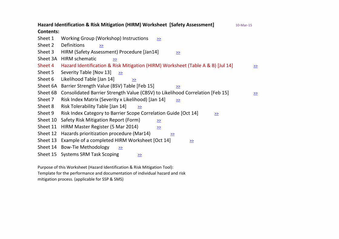
Hazard Identification & Risk Mitigation (HIRM) Worksheet [Safety Assessment] 10-Mar-15
Contents:Sheet 1 Working Group (Workshop) Instructions >>
Sheet 2 Definitions >>
Sheet 3 HIRM (Safety Assessment) Procedure [Jan14] >>
Sheet 3A HIRM schematic >>
Sheet 4 Hazard Identification & Risk Mitigation (HIRM) Worksheet (Table A & B) [Jul 14] >>
Sheet 5 Severity Table [Nov 13] >>
Sheet 6 Likelihood Table [Jan 14] >>
Sheet 6A Barrier Strength Value (BSV) Table [Feb 15] >>
Sheet 6B Consolidated Barrier Strength Value (CBSV) to Likelihood Correlation [Feb 15] >>
Sheet 7 Risk Index Matrix (Severity x Likelihood) [Jan 14] >>
Sheet 8 Risk Tolerability Table [Jan 14] >>
Sheet 9 Risk Index Category to Barrier Scope Correlation Guide [Oct 14] >>
Sheet 10 Safety Risk Mitigation Report (Form) >>
Sheet 11 HIRM Master Register (5 Mar 2014) >>
Sheet 12 Hazards prioritization procedure (Mar14) >>
Sheet 13 Example of a completed HIRM Worksheet [Oct 14] >>
Sheet 14 Bow-Tie Methodology >>
Sheet 15 Systems SRM Task Scoping >>
Purpose of this Worksheet (Hazard Identification & Risk Mitigation Tool):Template for the performance and documentation of individual hazard and risk mitigation process. (applicable for SSP & SMS)
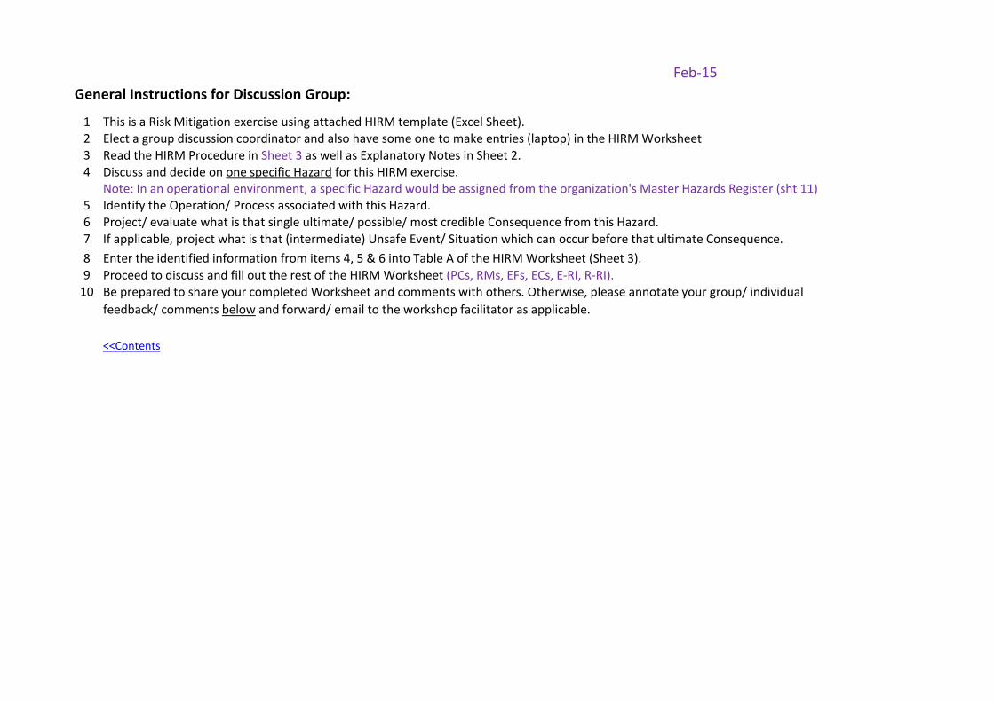
Feb-15General Instructions for Discussion Group:
1 This is a Risk Mitigation exercise using attached HIRM template (Excel Sheet). 2 Elect a group discussion coordinator and also have some one to make entries (laptop) in the HIRM Worksheet3 Read the HIRM Procedure in Sheet 3 as well as Explanatory Notes in Sheet 2.4 Discuss and decide on one specific Hazard for this HIRM exercise.
Note: In an operational environment, a specific Hazard would be assigned from the organization's Master Hazards Register (sht 11)5 Identify the Operation/ Process associated with this Hazard.6 Project/ evaluate what is that single ultimate/ possible/ most credible Consequence from this Hazard.78 Enter the identified information from items 4, 5 & 6 into Table A of the HIRM Worksheet (Sheet 3).9 Proceed to discuss and fill out the rest of the HIRM Worksheet (PCs, RMs, EFs, ECs, E-RI, R-RI).
10
<<Contents
If applicable, project what is that (intermediate) Unsafe Event/ Situation which can occur before that ultimate Consequence.
Be prepared to share your completed Worksheet and comments with others. Otherwise, please annotate your group/ individual feedback/ comments below and forward/ email to the workshop facilitator as applicable.
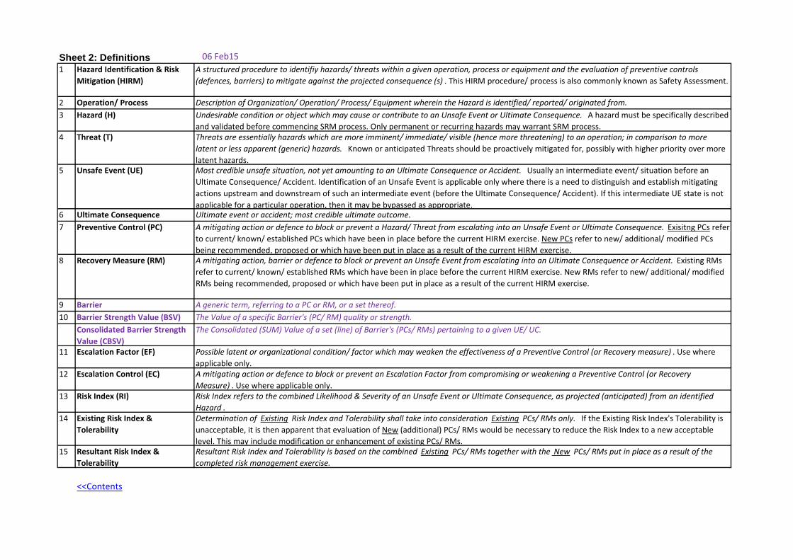
Sheet 2: Definitions 06 Feb151 Hazard Identification & Risk
Mitigation (HIRM)A structured procedure to identifiy hazards/ threats within a given operation, process or equipment and the evaluation of preventive controls (defences, barriers) to mitigate against the projected consequence (s) . This HIRM procedure/ process is also commonly known as Safety Assessment.
2 Operation/ Process Description of Organization/ Operation/ Process/ Equipment wherein the Hazard is identified/ reported/ originated from.3 Hazard (H) Undesirable condition or object which may cause or contribute to an Unsafe Event or Ultimate Consequence. A hazard must be specifically described
and validated before commencing SRM process. Only permanent or recurring hazards may warrant SRM process. 4 Threat (T) Threats are essentially hazards which are more imminent/ immediate/ visible (hence more threatening) to an operation; in comparison to more
latent or less apparent (generic) hazards. Known or anticipated Threats should be proactively mitigated for, possibly with higher priority over more latent hazards.
5 Unsafe Event (UE) Most credible unsafe situation, not yet amounting to an Ultimate Consequence or Accident. Usually an intermediate event/ situation before an Ultimate Consequence/ Accident. Identification of an Unsafe Event is applicable only where there is a need to distinguish and establish mitigating actions upstream and downstream of such an intermediate event (before the Ultimate Consequence/ Accident). If this intermediate UE state is not applicable for a particular operation, then it may be bypassed as appropriate.
6 Ultimate Consequence Ultimate event or accident; most credible ultimate outcome.7 Preventive Control (PC) A mitigating action or defence to block or prevent a Hazard/ Threat from escalating into an Unsafe Event or Ultimate Consequence. Exisitng PCs refer
to current/ known/ established PCs which have been in place before the current HIRM exercise. New PCs refer to new/ additional/ modified PCs being recommended, proposed or which have been put in place as a result of the current HIRM exercise.
8 Recovery Measure (RM) A mitigating action, barrier or defence to block or prevent an Unsafe Event from escalating into an Ultimate Consequence or Accident. Existing RMs refer to current/ known/ established RMs which have been in place before the current HIRM exercise. New RMs refer to new/ additional/ modified RMs being recommended, proposed or which have been put in place as a result of the current HIRM exercise.
9 Barrier A generic term, referring to a PC or RM, or a set thereof.10 Barrier Strength Value (BSV) The Value of a specific Barrier's (PC/ RM) quality or strength.
Consolidated Barrier Strength Value (CBSV)
The Consolidated (SUM) Value of a set (line) of Barrier's (PCs/ RMs) pertaining to a given UE/ UC.
11 Escalation Factor (EF) Possible latent or organizational condition/ factor which may weaken the effectiveness of a Preventive Control (or Recovery measure) . Use where applicable only.
12 Escalation Control (EC) A mitigating action or defence to block or prevent an Escalation Factor from compromising or weakening a Preventive Control (or Recovery Measure) . Use where applicable only.
13 Risk Index (RI) Risk Index refers to the combined Likelihood & Severity of an Unsafe Event or Ultimate Consequence, as projected (anticipated) from an identified Hazard .
14 Existing Risk Index & Tolerability
Determination of Existing Risk Index and Tolerability shall take into consideration Existing PCs/ RMs only. If the Existing Risk Index's Tolerability is unacceptable, it is then apparent that evaluation of New (additional) PCs/ RMs would be necessary to reduce the Risk Index to a new acceptable level. This may include modification or enhancement of existing PCs/ RMs.
15 Resultant Risk Index & Tolerability
Resultant Risk Index and Tolerability is based on the combined Existing PCs/ RMs together with the New PCs/ RMs put in place as a result of the completed risk management exercise.
<<Contents
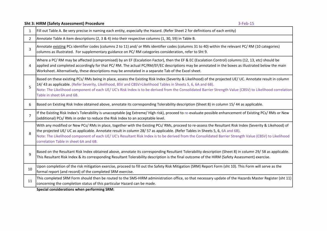
Sht 3: HIRM (Safety Assessment) Procedure 3-Feb-15
1
2
3
4
5
6
7
8
9
10
11
Special considerations when performing SRM:
Fill out Table A. Be very precise in naming each entity, especially the Hazard. (Refer Sheet 2 for definitions of each entity)
Annotate Table A item descriptions (2, 3 & 4) into their respective columns (1, 30, 59) in Table B.
Annotate existing PCs identifier codes (columns 2 to 11) and/ or RMs identifier codes (columns 31 to 40) within the relevant PC/ RM (10 categories) columns as illustrated. For supplementary guidance on PC/ RM categories consideration, refer to Sht 9.
Based on these existing PCs/ RMs being in place, assess the Existing Risk Index (Severity & Likelihood) of the projected UE/ UC. Annotate result in column 14/ 43 as applicable. (Refer Severity, Likelihood, BSV and CBSV>Likelihood Tables in Sheets 5, 6, 6A and 6B).Note: The Likelihood component of each UE/ UC's Risk Index is to be derived from the Consolidated Barrier Strength Value (CBSV) to Likelihood correlation Table in sheet 6A and 6B.
Based on Existing Risk Index obtained above, annotate its corresponding Tolerability description (Sheet 8) in column 15/ 44 as applicable.
Where a PC/ RM may be affected (compromised) by an EF (Escalation Factor), then the EF & EC (Escalation Control) columns (12, 13, etc) should be applied and completed accordingly for that PC/ RM. The actual PC/RM/EF/EC descriptions may be annotated in the boxes as illustrated below the main Worksheet. Alternatively, these descriptions may be annotated in a separate Tab of the Excel sheet.
Upon completion of the risk mitigation exercise, proceed to fill out the Safety Risk Mitigation (SRM) Report Form (sht 10). This Form will serve as the formal report (and record) of the completed SRM exercise.
This completed SRM Form should then be routed to the SMS-HIRM administration office, so that necessary update of the Hazards Master Register (sht 11) concerning the completion status of this particular Hazard can be made.
If the Existing Risk Index's Tolerability is unacceptable (eg Extreme/ High risk), proceed to re-evaluate possible enhancement of Existing PCs/ RMs or New (additional) PCs/ RMs in order to reduce the Risk Index to an acceptable level.
With any modified or New PCs/ RMs in place, together with the Existing PCs/ RMs, proceed to re-assess the Resultant Risk Index (Severity & Likehood) of the projected UE/ UC as applicable. Annotate result in column 28/ 57 as applicable. (Refer Tables in Sheets 5, 6, 6A and 6B).Note: The Likelihood component of each UE/ UC's Resultant Risk Index is to be derived from the Consolidated Barrier Strength Value (CBSV) to Likelihood correlation Table in sheet 6A and 6B.
Based on the Resultant Risk Index obtained above, annotate its corresponding Resultant Tolerability description (Sheet 8) in column 29/ 58 as applicable. This Resultant Risk Index & its corresponding Resultant Tolerability description is the final outcome of the HIRM (Safety Assessment) exercise.
<<Contents
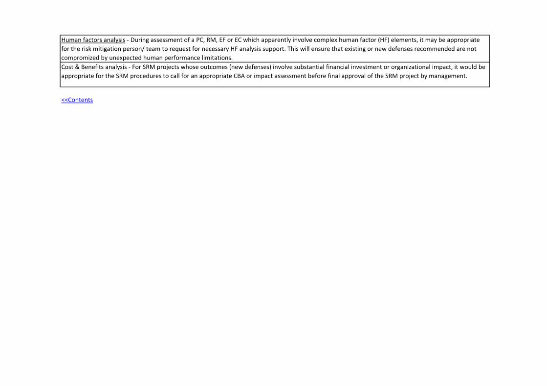
Human factors analysis - During assessment of a PC, RM, EF or EC which apparently involve complex human factor (HF) elements, it may be appropriate for the risk mitigation person/ team to request for necessary HF analysis support. This will ensure that existing or new defenses recommended are not compromized by unexpected human performance limitations.Cost & Benefits analysis - For SRM projects whose outcomes (new defenses) involve substantial financial investment or organizational impact, it would be appropriate for the SRM procedures to call for an appropriate CBA or impact assessment before final approval of the SRM project by management.
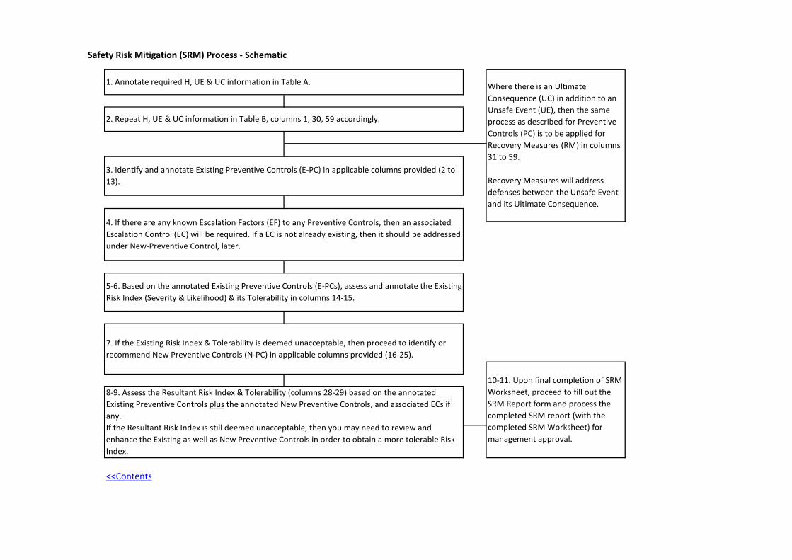
Safety Risk Mitigation (SRM) Process - Schematic
<<Contents
Where there is an Ultimate Consequence (UC) in addition to an Unsafe Event (UE), then the same process as described for Preventive Controls (PC) is to be applied for Recovery Measures (RM) in columns 31 to 59.
Recovery Measures will address defenses between the Unsafe Event and its Ultimate Consequence.
10-11. Upon final completion of SRM Worksheet, proceed to fill out the SRM Report form and process the completed SRM report (with the completed SRM Worksheet) for management approval.
4. If there are any known Escalation Factors (EF) to any Preventive Controls, then an associated Escalation Control (EC) will be required. If a EC is not already existing, then it should be addressed under New-Preventive Control, later.
5-6. Based on the annotated Existing Preventive Controls (E-PCs), assess and annotate the Existing Risk Index (Severity & Likelihood) & its Tolerability in columns 14-15.
7. If the Existing Risk Index & Tolerability is deemed unacceptable, then proceed to identify or recommend New Preventive Controls (N-PC) in applicable columns provided (16-25).
8-9. Assess the Resultant Risk Index & Tolerability (columns 28-29) based on the annotated Existing Preventive Controls plus the annotated New Preventive Controls, and associated ECs if any. If the Resultant Risk Index is still deemed unacceptable, then you may need to review and enhance the Existing as well as New Preventive Controls in order to obtain a more tolerable Risk Index.
1. Annotate required H, UE & UC information in Table A.
2. Repeat H, UE & UC information in Table B, columns 1, 30, 59 accordingly.
3. Identify and annotate Existing Preventive Controls (E-PC) in applicable columns provided (2 to 13).
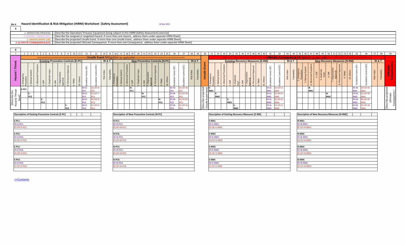
Hazard Identification & Risk Mitigation (HIRM) Worksheet [Safety Assessment] 18 Mar 2015
2 3 4 5 6 7 8 9 10 11 12 13 14 15 16 17 18 19 20 21 22 23 24 25 26 27 28 29 30 31 32 33 34 35 36 37 38 39 40 41 42 43 44 45 46 47 48 49 50 51 52 53 54 55 56 57 58 59
1. E
mer
genc
y Pr
oced
ure
2. B
acku
p Sy
stem
3. A
bnor
mal
Pro
cedu
re
4. S
OP
5. D
uplic
ate
Insp
n
6. G
M
7. O
rgan
izatio
n Ap
prov
al
8. P
erso
nnel
App
rova
l
9. T
RNG
10. O
ther
s
Esca
latio
n Fa
ctor
[EF]
Esca
latio
n Co
ntro
l [EC
]
Risk
Inde
x
Tole
rabi
lity
1. E
mer
genc
y Pr
oced
ure
2. B
acku
p Sy
stem
3. A
bnor
mal
Pro
cedu
re
4. S
OP
5. D
uplic
ate
Insp
n
6. G
M
7. O
rgan
izatio
n Ap
prov
al
8. P
erso
nnel
App
rova
l
9. T
RNG
10. O
ther
s
Esca
latio
n Fa
ctor
[EF]
Esca
latio
n Co
ntro
l [EC
]
Risk
Inde
x
Tole
rabi
lity
1. E
mer
genc
yPr
oced
ure
2. B
acku
p Sy
stem
3. A
bnor
mal
Pro
cedu
re
4. S
OP
5. D
uplic
ate
Insp
n
6. G
M
7. O
rgan
izatio
n Ap
prov
al
8. P
erso
nnel
App
rova
l
9. T
RNG
10. O
ther
s
Esca
latio
n Fa
ctor
[EF]
Esca
latio
n Co
ntro
l [EC
]
Ris
k In
dex
Tole
rabi
lity
1. E
mer
genc
yPr
oced
ure
2. B
acku
p Sy
stem
3. A
bnor
mal
Pro
cedu
re
4. S
OP
5. D
uplic
ate
Insp
n
6. G
M
7. O
rgan
izatio
n Ap
prov
al
8. P
erso
nnel
App
rova
l
9. T
RNG
10. O
ther
s
Esca
latio
n Fa
ctor
[EF]
Esca
latio
n Co
ntro
l [EC
]
Ris
k In
dex
Tole
rabi
lity
E-PC1 EF>E-PC1
EC>EF>E-PC1
N-PC1
EF>N-PC1
EC>EF>N-PC1
E-RM1
EF>E-RM1
EC>EF>E-RM1
N-RM1
EF>N-RM1
EC>EF>N-RM1
E-PC2
EF>E-PC2
EC>EF-F-PC2
N-PC2
EF>N-PC2
EC>EF>N-PC2
E-RM2
EF>E-RM2
EC>EF>E-RM2
N-RM2
EF>N-RM2
EC>EF>N-RM2
E-PC3
EF>E-PC3
EC>EF>E-PC3
N-PC3
EF>N-PC3
EC>EF>N-PC3
E-RM3
EF>E-RM3
EC>EF>E-RM3
EF>N-RM3
EC>EF>N-RM3
E-PC4
EF>E-PC4
EC>EF>E-PC4
EF>N-PC4
EC>EF>N-PC4
E-RM4
EF>E-RM4
EC>EF>E-RM4
EF>N-RM4
EC>EF>N-RM4
Description of Existing Preventive Controls [E-PC] Description of New Preventive Controls [N-PC] Description of Existing Recovery Measures [E-RM] Description of New Recovery Measures [N-RM]
<<Contents
E-RM2:EF>E-RM2: EC>EF>E-RM2:
E-RM3:EF>E-RM3:EC>EF>E-RM3:
E-RM4EF>E-RM4EC>EF>E-RM4
EF>N-RM1:EC>EF>N-RM1:
EF>N-RM4:EC>EF>N-RM4:
EC>EF>N-RM2:
N-RM3:EF>N-RM3:EC>EF>N-RM3:
N-RM4:EF>E-PC4:EC>EF>E-PC4:
N-PC2:
EC>EF>N-PC2:
N-PC3:EF>N-PC3:EC>EF>N-PC3:
N-PC4:EF>N-PC4:EC>EF>N-PC4:
EC>EF>E-PC2:
E-PC3:EF>E-PC3:EC>EF>E-PC3:
E-PC4:
E-PC2:EF>E-PC2:
N-RM2:EF>N-RM2:
EC>EF>N-PC1:
E-RM1: EF>E-RM1:EC>EF>E-RM1:
E-PC1: EF>E-PC1:EC>EF>E-PC1:
EF>N-PC2:
Uns
afe
Even
tRI & T
N-PC1: EF>N-PC1:
N-RM1:
A
1. OPERATION/ PROCESS: 2. HAZARD / THREAT [H/T]:
3. UNSAFE EVENT [UE]: 4. ULTIMATE CONSEQUENCE [UC]:
B1
Haz
ard
/ Thr
eat
[Des
crib
e th
e Ha
zard
/ THr
eat
here
]
>>>>>>>>>>>>>>>>>>>>>>>>>>>>>>>>>>>> Unsafe Event Mitigation (as applicable) >>>>>>>>>>>>>>>>>>>>>>>>>>>>>>>>>>>>
Sht 4
New Preventive Controls [N-PC] New Recovery Measures [N-RM] Existing Recovery Measures [E-RM]
[Describe the Operation/ Process/ Equipment being subject to this HIRM (Safety Assessment) exercise] [Describe the assigned or targetted Hazard. If more than one Hazard, address them under separate HIRM Sheet] [Describe the projected Unsafe Event. If more than one Unsafe Event, address them under separate HIRM Sheet] [Describe the projected Ultimate Consequence. If more than one Consequence, address them under separate HIRM Sheet]
RI & T RI & T
[Des
crib
e pr
ojec
ted
Ulti
mat
e Co
nseq
uenc
e /
[Des
crib
e pr
ojec
ted
Uns
afe
Even
t her
e]
Ulti
mat
e C
onse
quen
ce
Existing Preventive Controls [E-PC] RI & T>>>>>>>>>>>>>>>>>>>>>>>>>>>>>>>> Ultimate Consequence Mitigation (as applicable) >>>>>>>>>>>>>>>>>>>>>>>>>>>>>>>>
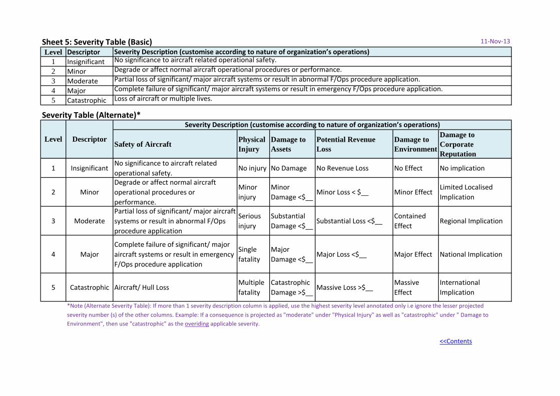
Sheet 5: Severity Table (Basic) 11-Nov-13
Level Descriptor1 Insignificant2 Minor3 Moderate4 Major5 Catastrophic
Severity Table (Alternate)*
Safety of Aircraft Physical Injury
Damage to Assets
Potential Revenue Loss
Damage to Environment
Damage to Corporate Reputation
1 InsignificantNo significance to aircraft related operational safety.
No injury No Damage No Revenue Loss No Effect No implication
2 MinorDegrade or affect normal aircraft operational procedures or performance.
Minor injury
Minor Damage <$__
Minor Loss < $__ Minor EffectLimited Localised Implication
3 ModeratePartial loss of significant/ major aircraft systems or result in abnormal F/Ops procedure application
Serious injury
Substantial Damage <$__
Substantial Loss <$__Contained Effect
Regional Implication
4 MajorComplete failure of significant/ major aircraft systems or result in emergency F/Ops procedure application
Single fatality
Major Damage <$__
Major Loss <$__ Major Effect National Implication
5 Catastrophic Aircraft/ Hull LossMultiple fatality
Catastrophic Damage >$__
Massive Loss >$__Massive Effect
International Implication
*Note (Alternate Severity Table): If more than 1 severity description column is applied, use the highest severity level annotated only i.e ignore the lesser projectedseverity number (s) of the other columns. Example: If a consequence is projected as "moderate" under "Physical Injury" as well as "catastrophic" under " Damage to Environment", then use "catastrophic" as the overiding applicable severity.
<<Contents
Severity Description (customise according to nature of organization’s operations)No significance to aircraft related operational safety.Degrade or affect normal aircraft operational procedures or performance.
Level Descriptor
Severity Description (customise according to nature of organization’s operations)
Partial loss of significant/ major aircraft systems or result in abnormal F/Ops procedure application.Complete failure of significant/ major aircraft systems or result in emergency F/Ops procedure application.Loss of aircraft or multiple lives.
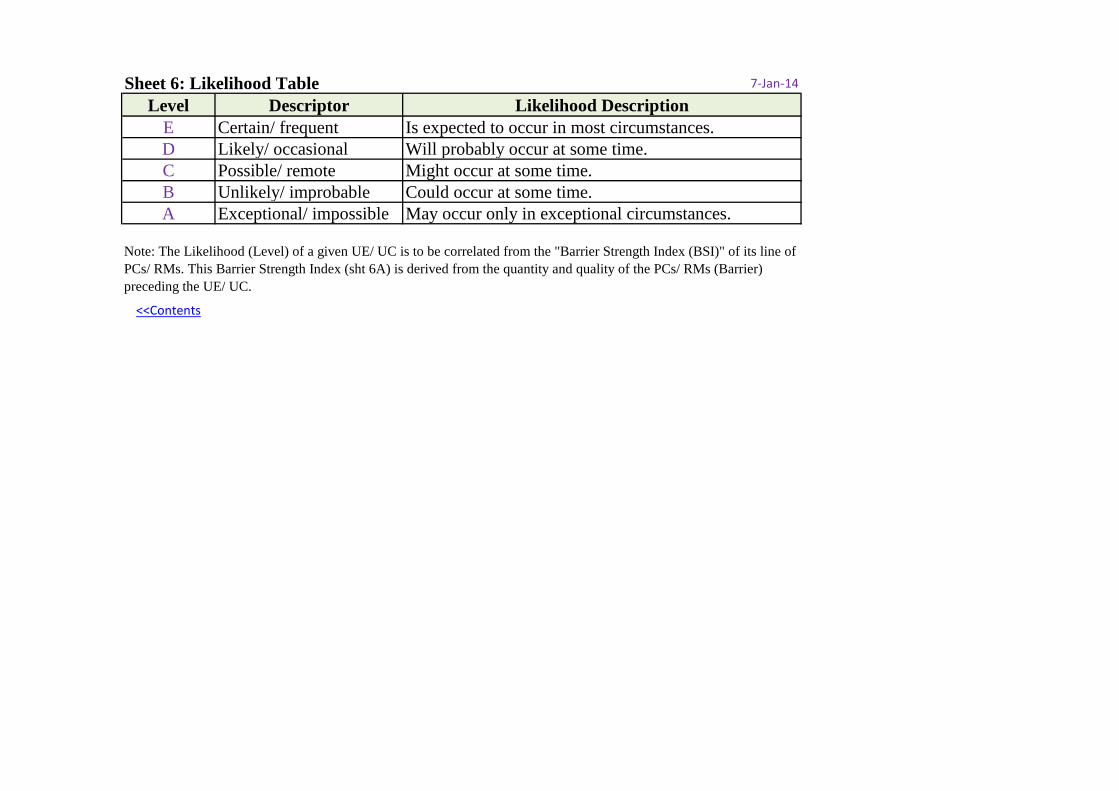
Sheet 6: Likelihood Table 7-Jan-14
Level Descriptor Likelihood DescriptionE Certain/ frequent Is expected to occur in most circumstances.D Likely/ occasional Will probably occur at some time.C Possible/ remote Might occur at some time.B Unlikely/ improbable Could occur at some time.A Exceptional/ impossible May occur only in exceptional circumstances.
<<Contents
Note: The Likelihood (Level) of a given UE/ UC is to be correlated from the "Barrier Strength Index (BSI)" of its line of PCs/ RMs. This Barrier Strength Index (sht 6A) is derived from the quantity and quality of the PCs/ RMs (Barrier) preceding the UE/ UC.
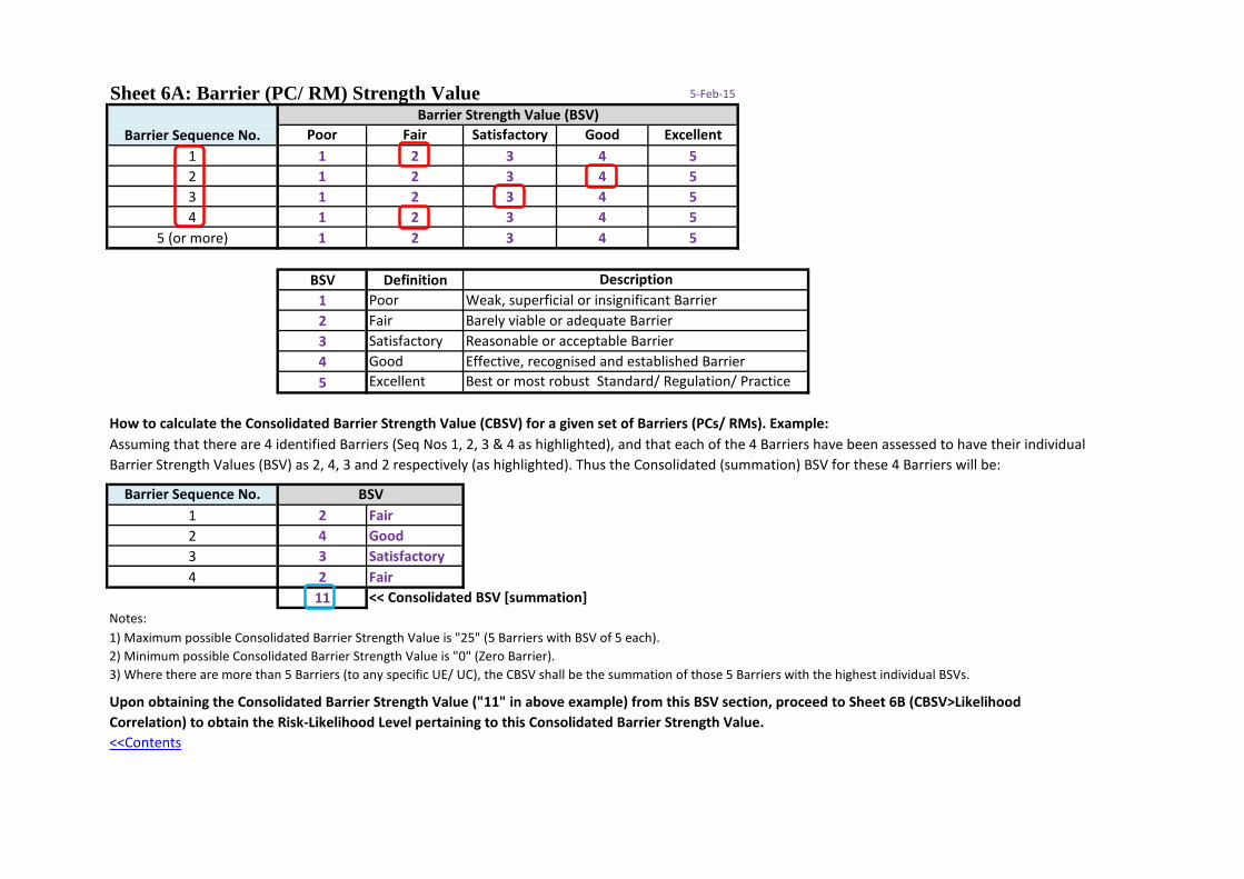
Sheet 6A: Barrier (PC/ RM) Strength Value 5-Feb-15
Poor Fair Satisfactory Good Excellent1 1 2 3 4 52 1 2 3 4 53 1 2 3 4 54 1 2 3 4 5
5 (or more) 1 2 3 4 5
BSV Definition1 Poor2 Fair3 Satisfactory4 Good5 Excellent
How to calculate the Consolidated Barrier Strength Value (CBSV) for a given set of Barriers (PCs/ RMs). Example:
Barrier Sequence No.1 2 Fair2 4 Good3 3 Satisfactory4 2 Fair
11Notes:
<<Contents
Upon obtaining the Consolidated Barrier Strength Value ("11" in above example) from this BSV section, proceed to Sheet 6B (CBSV>Likelihood Correlation) to obtain the Risk-Likelihood Level pertaining to this Consolidated Barrier Strength Value.
Assuming that there are 4 identified Barriers (Seq Nos 1, 2, 3 & 4 as highlighted), and that each of the 4 Barriers have been assessed to have their individual Barrier Strength Values (BSV) as 2, 4, 3 and 2 respectively (as highlighted). Thus the Consolidated (summation) BSV for these 4 Barriers will be:
<< Consolidated BSV [summation]
1) Maximum possible Consolidated Barrier Strength Value is "25" (5 Barriers with BSV of 5 each).2) Minimum possible Consolidated Barrier Strength Value is "0" (Zero Barrier).3) Where there are more than 5 Barriers (to any specific UE/ UC), the CBSV shall be the summation of those 5 Barriers with the highest individual BSVs.
BSV
Best or most robust Standard/ Regulation/ Practice
Barrier Strength Value (BSV)Barrier Sequence No.
DescriptionWeak, superficial or insignificant BarrierBarely viable or adequate BarrierReasonable or acceptable BarrierEffective, recognised and established Barrier
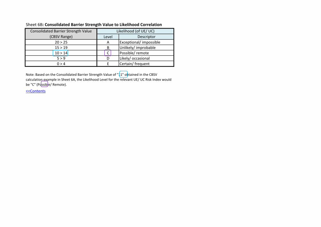
Sheet 6B: Consolidated Barrier Strength Value to Likelihood Correlation
Level Descriptor20 > 25 A Exceptional/ impossible15 > 19 B Unlikely/ improbable10 > 14 C Possible/ remote
5 > 9 D Likely/ occasional0 > 4 E Certain/ frequent
<<Contents
Consolidated Barrier Strength Value (CBSV Range)
Likelihood (of UE/ UC)
Note: Based on the Consolidated Barrier Strength Value of "11" obtained in the CBSV calculation example in Sheet 6A, the Likelihood Level for the relevant UE/ UC Risk Index would be "C" (Possible/ Remote).
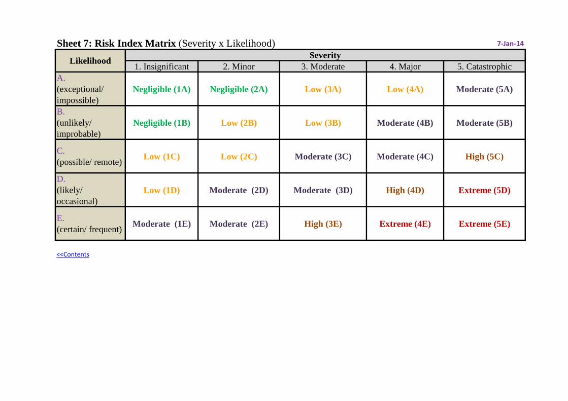
Sheet 7: Risk Index Matrix (Severity x Likelihood) 7-Jan-14
1. Insignificant 2. Minor 3. Moderate 4. Major 5. CatastrophicA. (exceptional/ impossible)
Negligible (1A) Negligible (2A) Low (3A) Low (4A) Moderate (5A)
B. (unlikely/ improbable)
Negligible (1B) Low (2B) Low (3B) Moderate (4B) Moderate (5B)
C. (possible/ remote) Low (1C) Low (2C) Moderate (3C) Moderate (4C) High (5C)
D. (likely/ occasional)
Low (1D) Moderate (2D) Moderate (3D) High (4D) Extreme (5D)
E. (certain/ frequent) Moderate (1E) Moderate (2E) High (3E) Extreme (4E) Extreme (5E)
<<Contents
Likelihood Severity
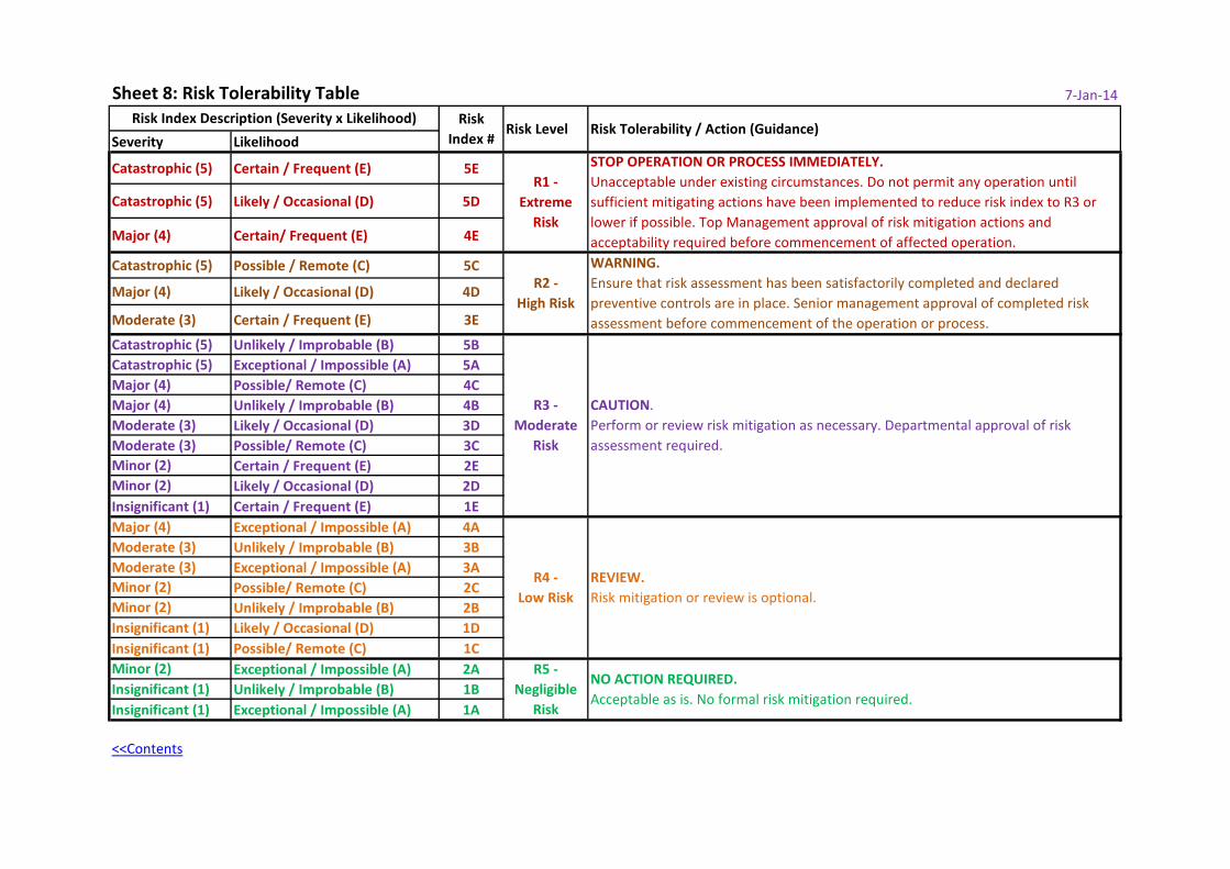
Sheet 8: Risk Tolerability Table 7-Jan-14
Severity Likelihood
Catastrophic (5) Certain / Frequent (E) 5E
Catastrophic (5) Likely / Occasional (D) 5D
Major (4) Certain/ Frequent (E) 4E
Catastrophic (5) Possible / Remote (C) 5C
Major (4) Likely / Occasional (D) 4D
Moderate (3) Certain / Frequent (E) 3E
Catastrophic (5) Unlikely / Improbable (B) 5BCatastrophic (5) Exceptional / Impossible (A) 5AMajor (4) Possible/ Remote (C) 4CMajor (4) Unlikely / Improbable (B) 4BModerate (3) Likely / Occasional (D) 3DModerate (3) Possible/ Remote (C) 3CMinor (2) Certain / Frequent (E) 2EMinor (2) Likely / Occasional (D) 2DInsignificant (1) Certain / Frequent (E) 1EMajor (4) Exceptional / Impossible (A) 4AModerate (3) Unlikely / Improbable (B) 3BModerate (3) Exceptional / Impossible (A) 3AMinor (2) Possible/ Remote (C) 2CMinor (2) Unlikely / Improbable (B) 2BInsignificant (1) Likely / Occasional (D) 1DInsignificant (1) Possible/ Remote (C) 1CMinor (2) Exceptional / Impossible (A) 2AInsignificant (1) Unlikely / Improbable (B) 1BInsignificant (1) Exceptional / Impossible (A) 1A
<<Contents
WARNING. Ensure that risk assessment has been satisfactorily completed and declared preventive controls are in place. Senior management approval of completed risk assessment before commencement of the operation or process.
R2 - High Risk
R4 - Low Risk
REVIEW. Risk mitigation or review is optional.
R5 - Negligible
Risk
NO ACTION REQUIRED. Acceptable as is. No formal risk mitigation required.
R3 - Moderate
Risk
CAUTION. Perform or review risk mitigation as necessary. Departmental approval of risk assessment required.
Risk Index Description (Severity x Likelihood)
STOP OPERATION OR PROCESS IMMEDIATELY. Unacceptable under existing circumstances. Do not permit any operation until sufficient mitigating actions have been implemented to reduce risk index to R3 or lower if possible. Top Management approval of risk mitigation actions and acceptability required before commencement of affected operation.
R1 - Extreme
Risk
Risk Index #
Risk Level Risk Tolerability / Action (Guidance)
Severity Likelihood
1. E
RP
2. B
acku
p Sy
stem
3. A
bnor
mal
Pr
oced
ure
4. S
ched
uled
M
aint
.
5. S
OP
6. S
peci
al/
Dupl
icat
e In
spn
7. G
M
8. O
rgn
Appr
oval
9. P
erso
nnel
Ap
prov
al
10. T
RNG
11. R
egul
atio
n
12. O
ther
s (s
peci
fy)
Inte
rnat
iona
l/
Regi
onal
or
gani
zatio
n
CAA
Serv
ice
Prov
ider
Catastrophic (5) Certain / Frequent (E) 5ECatastrophic (5) Likely / Occasional (D) 5DMajor (4) Certain/ Frequent (E) 4ECatastrophic (5) Possible / Remote (C) 5CMajor (4) Likely / Occasional (D) 4DModerate (3) Certain / Frequent (E) 3ECatastrophic (5) Unlikely / Improbable (B) 5BCatastrophic (5) Exceptional / Impossible (A) 5AMajor (4) Possible/ Remote (C) 4CMajor (4) Unlikely / Improbable (B) 4BModerate (3) Likely / Occasional (D) 3DModerate (3) Possible/ Remote (C) 3CMinor (2) Certain / Frequent (E) 2EMinor (2) Likely / Occasional (D) 2DInsignificant (1) Certain / Frequent (E) 1EMajor (4) Exceptional / Impossible (A) 4AModerate (3) Unlikely / Improbable (B) 3BModerate (3) Exceptional / Impossible (A) 3AMinor (2) Possible/ Remote (C) 2CMinor (2) Unlikely / Improbable (B) 2BInsignificant (1) Likely / Occasional (D) 1DInsignificant (1) Possible/ Remote (C) 1CMinor (2) Exceptional / Impossible (A) 2AInsignificant (1) Unlikely / Improbable (B) 1BInsignificant (1) Exceptional / Impossible (A) 1A
<<Contents
_
_
Opt
iona
l
Yes
Yes
_
Opt
iona
l
Yes Yes
Opt
iona
l
Yes_ Yes
Yes
_
Opt
iona
l
Yes
Yes Yes
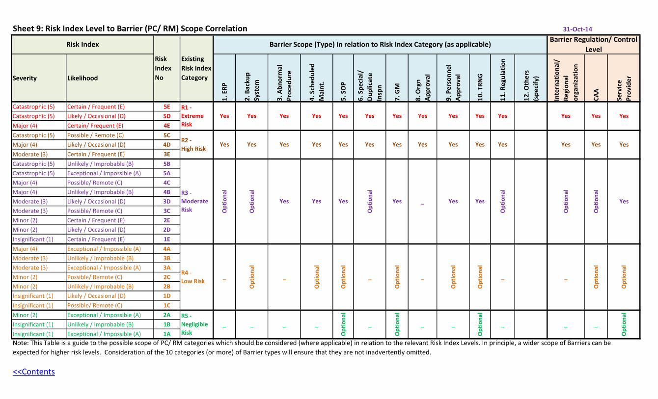
Note: This Table is a guide to the possible scope of PC/ RM categories which should be considered (where applicable) in relation to the relevant Risk Index Levels. In principle, a wider scope of Barriers can be expected for higher risk levels. Consideration of the 10 categories (or more) of Barrier types will ensure that they are not inadvertently omitted.
31-Oct-14Sheet 9: Risk Index Level to Barrier (PC/ RM) Scope Correlation
Existing Risk Index Category
Risk Index
Risk Index No
Opt
iona
l
_
Opt
iona
l
Opt
iona
l
_
Opt
iona
l
Yes Yes
Yes
Opt
iona
l
Yes
Opt
iona
l
Barrier Regulation/ Control Level
Barrier Scope (Type) in relation to Risk Index Category (as applicable)
Yes Yes Yes Yes YesYes YesYes YesYes YesYes Yes
_R5 - Negligible Risk
_ _ _
R1 - Extreme Risk
_
Yes
Opt
iona
lO
ptio
nal
_
Opt
iona
l
Opt
iona
l
_ _
Opt
iona
l
YesYes
Opt
iona
l
_
Opt
iona
l
YesYesR2 - High Risk
R3 - Moderate Risk
R4 - Low Risk
Yes Yes
Yes
Opt
iona
l
_
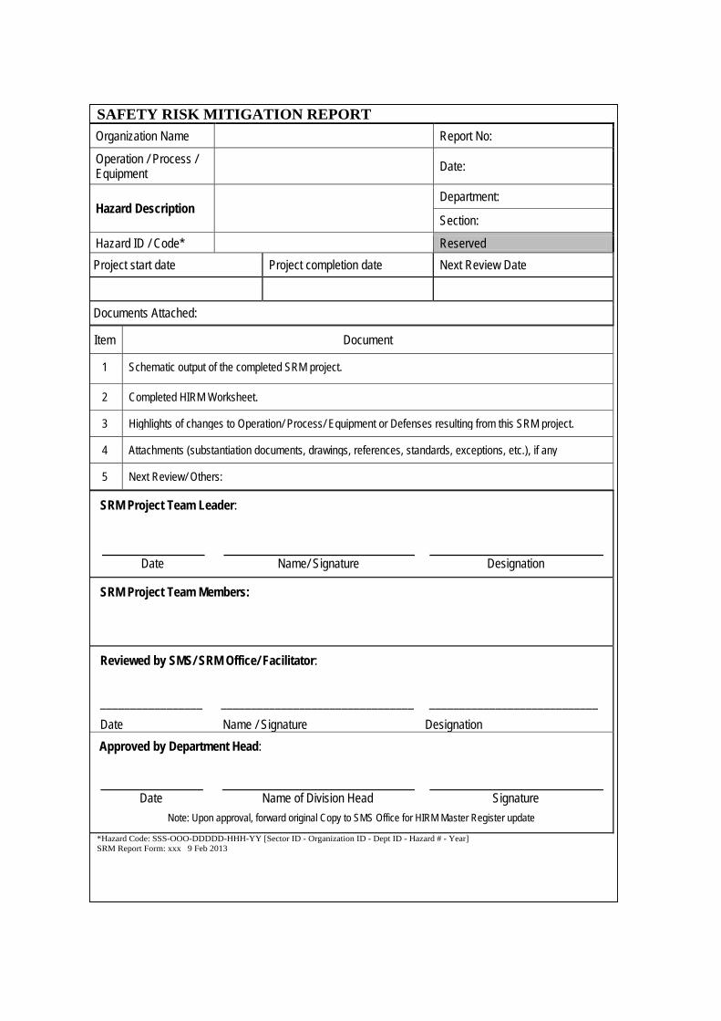
SAFETY RISK MITIGATION REPORT Organization Name Report No:
Operation / Process / Equipment Date:
Hazard Description Department:
Section:
Hazard ID / Code* Reserved Project start date Project completion date Next Review Date
Documents Attached:
Item Document
1 Schematic output of the completed SRM project.
2 Completed HIRM Worksheet.
3 Highlights of changes to Operation/ Process/ Equipment or Defenses resulting from this SRM project.
4 Attachments (substantiation documents, drawings, references, standards, exceptions, etc.), if any
5 Next Review/ Others:
SRM Project Team Leader:
Date Name/ Signature Designation
SRM Project Team Members:
Reviewed by SMS/ SRM Office/ Facilitator: _________________ ________________________________ ____________________________ Date Name / Signature Designation Approved by Department Head:
Date Name of Division Head Signature Note: Upon approval, forward original Copy to SMS Office for HIRM Master Register update
*Hazard Code: SSS-OOO-DDDDD-HHH-YY [Sector ID - Organization ID - Dept ID - Hazard # - Year] SRM Report Form: xxx 9 Feb 2013
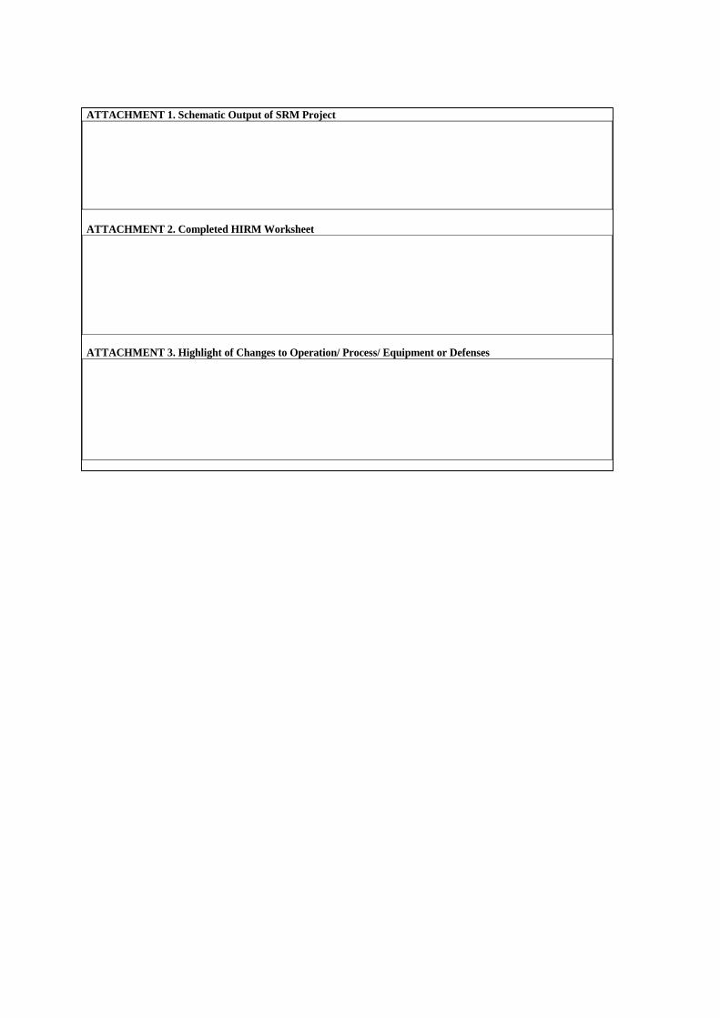
ATTACHMENT 1. Schematic Output of SRM Project ATTACHMENT 2. Completed HIRM Worksheet ATTACHMENT 3. Highlight of Changes to Operation/ Process/ Equipment or Defenses
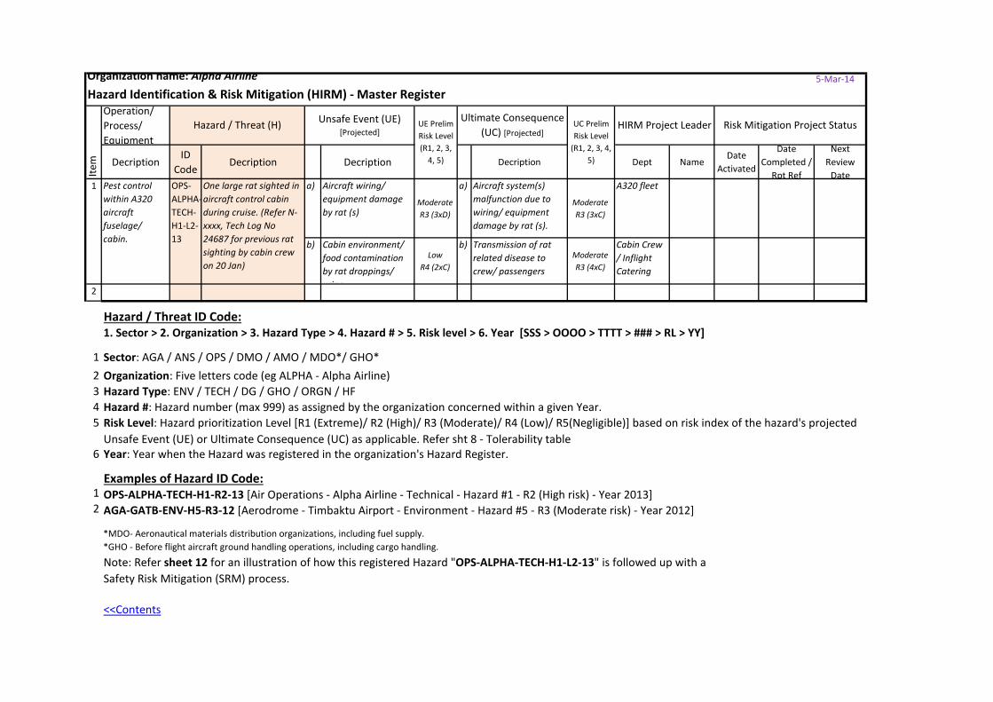
Organization name: Alpha Airline 5-Mar-14
Hazard Identification & Risk Mitigation (HIRM) - Master RegisterOperation/ Process/ Equipment
DecriptionID
CodeDecription Decription Decription Dept Name
Date Activated
Date Completed /
Rpt Ref
Next Review
Datea) Aircraft wiring/
equipment damage by rat (s)
ModerateR3 (3xD)
a) Aircraft system(s) malfunction due to wiring/ equipment damage by rat (s).
ModerateR3 (3xC)
A320 fleet
b) Cabin environment/ food contamination by rat droppings/ urine
LowR4 (2xC)
b) Transmission of rat related disease to crew/ passengers
ModerateR3 (4xC)
Cabin Crew / Inflight Catering
2
Hazard / Threat ID Code:1. Sector > 2. Organization > 3. Hazard Type > 4. Hazard # > 5. Risk level > 6. Year [SSS > OOOO > TTTT > ### > RL > YY]
12 Organization: Five letters code (eg ALPHA - Alpha Airline)3 Hazard Type: ENV / TECH / DG / GHO / ORGN / HF4 Hazard #: Hazard number (max 999) as assigned by the organization concerned within a given Year.5
6 Year: Year when the Hazard was registered in the organization's Hazard Register.
Examples of Hazard ID Code:1 OPS-ALPHA-TECH-H1-R2-13 [Air Operations - Alpha Airline - Technical - Hazard #1 - R2 (High risk) - Year 2013]2 AGA-GATB-ENV-H5-R3-12 [Aerodrome - Timbaktu Airport - Environment - Hazard #5 - R3 (Moderate risk) - Year 2012]
<<Contents
Item
Note: Refer sheet 12 for an illustration of how this registered Hazard "OPS-ALPHA-TECH-H1-L2-13" is followed up with a Safety Risk Mitigation (SRM) process.
*MDO- Aeronautical materials distribution organizations, including fuel supply.*GHO - Before flight aircraft ground handling operations, including cargo handling.
UE Prelim Risk Level (R1, 2, 3,
4, 5)
Risk Level: Hazard prioritization Level [R1 (Extreme)/ R2 (High)/ R3 (Moderate)/ R4 (Low)/ R5(Negligible)] based on risk index of the hazard's projected Unsafe Event (UE) or Ultimate Consequence (UC) as applicable. Refer sht 8 - Tolerability table
Risk Mitigation Project StatusHazard / Threat (H) Unsafe Event (UE)[Projected]
Ultimate Consequence (UC) [Projected]
HIRM Project Leader
Sector: AGA / ANS / OPS / DMO / AMO / MDO*/ GHO*
1 Pest control within A320 aircraft fuselage/ cabin.
OPS-ALPHA-TECH-H1-L2-13
One large rat sighted in aircraft control cabin during cruise. (Refer N-xxxx, Tech Log No 24687 for previous rat sighting by cabin crew on 20 Jan)
UC Prelim Risk Level
(R1, 2, 3, 4, 5)
SMM Appendix 3, chapter 2 (updated Mar 2014)<<Contents
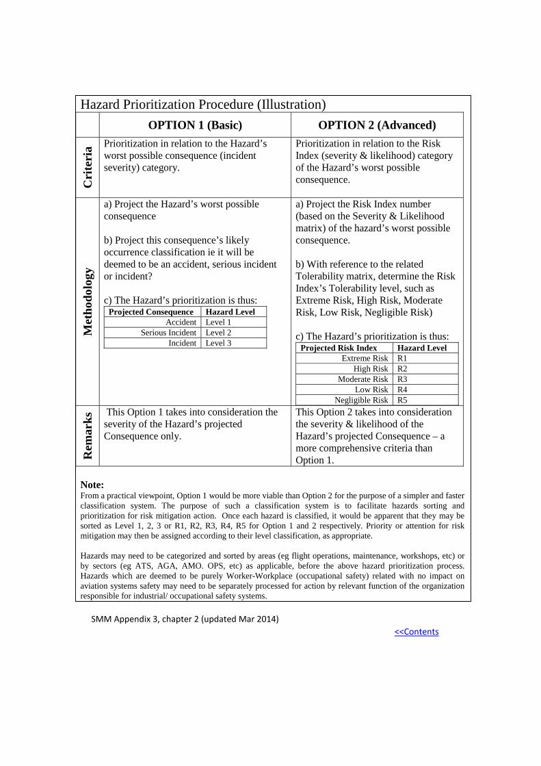
Hazard Prioritization Procedure (Illustration) OPTION 1 (Basic) OPTION 2 (Advanced)
Cri
teri
a Prioritization in relation to the Hazard’s worst possible consequence (incident severity) category.
Prioritization in relation to the Risk Index (severity & likelihood) category of the Hazard’s worst possible consequence.
Met
hodo
logy
a) Project the Hazard’s worst possible consequence b) Project this consequence’s likely occurrence classification ie it will be deemed to be an accident, serious incident or incident? c) The Hazard’s prioritization is thus:
Projected Consequence Hazard Level Accident Level 1
Serious Incident Level 2 Incident Level 3
a) Project the Risk Index number (based on the Severity & Likelihood matrix) of the hazard’s worst possible consequence. b) With reference to the related Tolerability matrix, determine the Risk Index’s Tolerability level, such as Extreme Risk, High Risk, Moderate Risk, Low Risk, Negligible Risk) c) The Hazard’s prioritization is thus:
Projected Risk Index Hazard Level Extreme Risk R1
High Risk R2 Moderate Risk R3
Low Risk R4 Negligible Risk R5
Rem
arks
This Option 1 takes into consideration the severity of the Hazard’s projected Consequence only.
This Option 2 takes into consideration the severity & likelihood of the Hazard’s projected Consequence – a more comprehensive criteria than Option 1.
Note: From a practical viewpoint, Option 1 would be more viable than Option 2 for the purpose of a simpler and faster classification system. The purpose of such a classification system is to facilitate hazards sorting and prioritization for risk mitigation action. Once each hazard is classified, it would be apparent that they may be sorted as Level 1, 2, 3 or R1, R2, R3, R4, R5 for Option 1 and 2 respectively. Priority or attention for risk mitigation may then be assigned according to their level classification, as appropriate. Hazards may need to be categorized and sorted by areas (eg flight operations, maintenance, workshops, etc) or by sectors (eg ATS, AGA, AMO. OPS, etc) as applicable, before the above hazard prioritization process. Hazards which are deemed to be purely Worker-Workplace (occupational safety) related with no impact on aviation systems safety may need to be separately processed for action by relevant function of the organization responsible for industrial/ occupational safety systems.
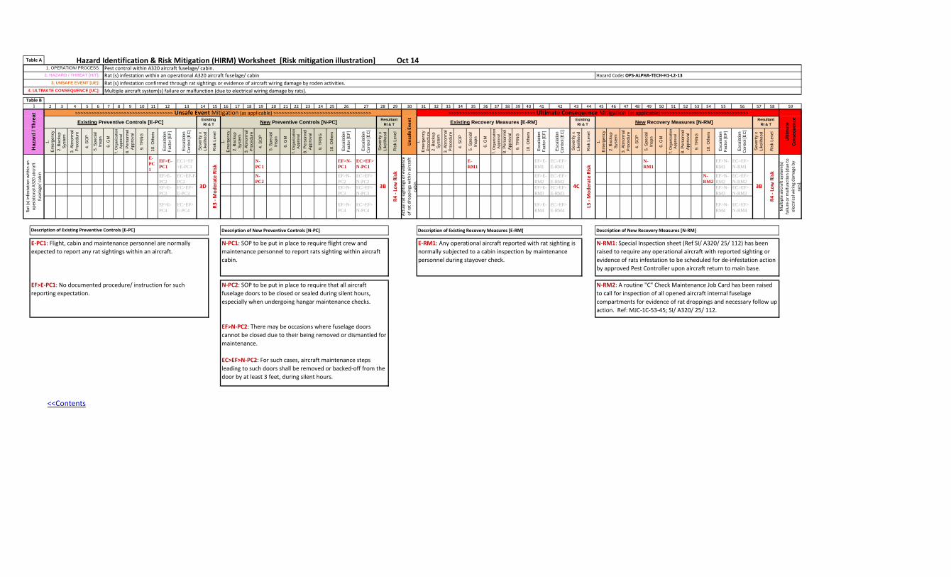
Hazard Identification & Risk Mitigation (HIRM) Worksheet [Risk mitigation illustration] Oct 14
2 3 4 5 6 7 8 9 10 11 12 13 14 15 16 17 18 19 20 21 22 23 24 25 26 27 28 29 30 31 32 33 34 35 36 37 38 39 40 41 42 43 44 45 46 47 48 49 50 51 52 53 54 55 56 57 58 59
1.
Em
erge
ncy
2. B
acku
p S
yste
m
3. A
bnor
mal
P
roce
dure
4. S
OP
5. S
peci
al
Insp
n
6. G
M
7. O
rgan
izat
ion
App
rova
l
8. P
erso
nnel
A
ppro
val
9. T
RN
G
10. O
ther
s
Esc
alat
ion
Fact
or [E
F]
Esc
alat
ion
Con
trol [
EC
]
Sev
erity
x
Like
lihoo
d
Ris
k Le
vel
1.
Em
erge
ncy
2. B
acku
p S
yste
m3.
Abn
orm
al
Pro
cedu
re
4. S
OP
5. S
peci
al
Insp
n
6. G
M
7. O
rgan
izat
ion
App
rova
l
8. P
erso
nnel
A
ppro
val
9. T
RN
G
10. O
ther
s
Esc
alat
ion
Fact
or [E
F]
Esc
alat
ion
Con
trol [
EC
]
Sev
erity
x
Like
lihoo
d
Ris
k Le
vel
1.
Em
erge
ncy
Pro
cedu
re2.
Bac
kup
Sys
tem
3. A
bnor
mal
P
roce
dure
4. S
OP
5. S
peci
al
Insp
n
6. G
M
7. O
rgan
izat
ion
App
rova
l8.
Per
sonn
el
App
rova
l
9. T
RN
G
10. O
ther
s
Esc
alat
ion
Fact
or [E
F]
Esc
alat
ion
Con
trol [
EC
]
Sev
erity
x
Like
lihoo
d
Ris
k Le
vel
1.
Em
erge
ncy
2. B
acku
p S
yste
m
3. A
bnor
mal
P
roce
dure
4. S
OP
5. S
peci
al
Insp
n
6. G
M
7. O
rgan
izat
ion
App
rova
l
8. P
erso
nnel
A
ppro
val
9. T
RN
G
10. O
ther
s
Esc
alat
ion
Fact
or [E
F]
Esc
alat
ion
Con
trol [
EC
]
Sev
erity
x
Like
lihoo
d
Ris
k Le
vel
E-PC1
EF>E-PC1
EC1>EF>E-PC1
N-PC1
EF>N-PC1
EC>EF>N-PC1
E-RM1
EF>E-RM1
EC>EF>E-RM1
N-RM1
EF>N-RM1
EC>EF>N-RM1
EF>E-PC2
EC>EF-F-PC2
N-PC2
EF>N-PC2
EC>EF>N-PC2
EF>E-RM2
EC>EF>E-RM2
N-RM2
EF>N-RM2
EC>EF>N-RM2
EF>E-PC3
EC>EF>E-PC3
EF>N-PC3
EC>EF>N-PC3
EF>E-RM3
EC>EF>E-RM3
EF>N-RM3
EC>EF>N-RM3
EF>E-PC4
EC>EF>E-PC4
EF>N-PC4
EC>EF>N-PC4
EF>E-RM4
EC>EF>E-RM4
EF>N-RM4
EC>EF>N-RM4
Description of New Preventive Controls [N-PC] Description of Existing Recovery Measures [E-RM] Description of New Recovery Measures [N-RM]
4. ULTIMATE CONSEQUENCE [UC]: Multiple aircraft system(s) failure or malfunction (due to electrical wiring damage by rats).
Table A1. OPERATION/ PROCESS: Pest control within A320 aircraft fuselage/ cabin.
2. HAZARD / THREAT [H/T]: Rat (s) infestation within an operational A320 aircraft fuselage/ cabin Hazard Code: OPS-ALPHA-TECH-H1-L2-133. UNSAFE EVENT [UE]: Rat (s) infestation confirmed through rat sightings or evidence of aircraft wiring damage by roden activities.
Table B1
Haz
ard
/ Thr
eat >>>>>>>>>>>>>>>>>>>>>>>>>>>>>>>>>>>> Unsafe Event Mitigation (as applicable) >>>>>>>>>>>>>>>>>>>>>>>>>>>>>>>>>>>>
Uns
afe
Even
t
Ulti
mat
e Co
nseq
uenc
e
Existing Preventive Controls [E-PC] ExistingRI & T New Preventive Controls [N-PC] Resultant
RI & T Existing Recovery Measures [E-RM] Existing RI & T New Recovery Measures [N-RM] Resultant
RI & T
>>>>>>>>>>>>>>>>>>>>>>>>>>>>>>>> Ultimate Consequence Mitigation (as applicable) >>>>>>>>>>>>>>>>>>>>>>>>>>>>>>>>
Rat (
s) in
fest
atio
n w
ithin
an
oper
atio
nal A
320
airc
raft
fu
sela
ge/ c
abin
3D
R3 -
Mod
erat
e Ri
sk
3B
R4 -
Low
Ris
k
Mul
tiple
airc
raft
syst
em(s
) fa
ilure
or m
alfu
nctio
n (d
ue to
el
ectr
ical
wiri
ng d
amag
e by
ra
ts).
Actu
al ra
t sig
htin
gs o
r evi
denc
e of
rat d
ropp
ings
with
in a
ircra
ft
cabi
n.
4C
L3 -
Mod
erat
e Ri
sk
3B
R4 -
Low
Ris
k
N-RM2: A routine "C" Check Maintenance Job Card has been raised to call for inspection of all opened aircraft internal fuselage compartments for evidence of rat droppings and necessary follow up action. Ref: MJC-1C-53-45; SI/ A320/ 25/ 112.
Description of Existing Preventive Controls [E-PC]
E-PC1: Flight, cabin and maintenance personnel are normally expected to report any rat sightings within an aircraft.
N-PC1: SOP to be put in place to require flight crew and maintenance personnel to report rats sighting within aircraft cabin.
E-RM1: Any operational aircraft reported with rat sighting is normally subjected to a cabin inspection by maintenance personnel during stayover check.
N-RM1: Special Inspection sheet (Ref SI/ A320/ 25/ 112) has been raised to require any operational aircraft with reported sighting or evidence of rats infestation to be scheduled for de-infestation action by approved Pest Controller upon aircraft return to main base.
EF>E-PC1: No documented procedure/ instruction for such reporting expectation.
N-PC2: SOP to be put in place to require that all aircraft fuselage doors to be closed or sealed during silent hours, especially when undergoing hangar maintenance checks.
EF>N-PC2: There may be occasions where fuselage doors cannot be closed due to their being removed or dismantled for maintenance.
EC>EF>N-PC2: For such cases, aircraft maintenance steps leading to such doors shall be removed or backed-off from the door by at least 3 feet, during silent hours.
<<Contents
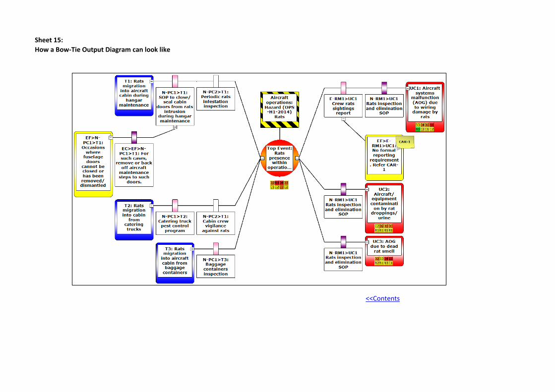
Sheet 15: How a Bow-Tie Output Diagram can look like
<<Contents
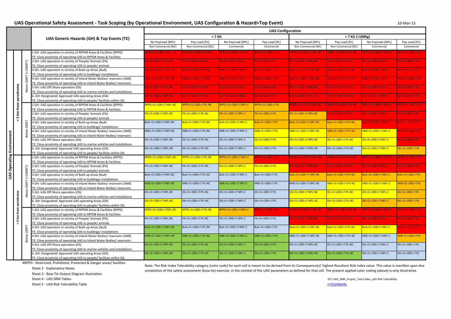
UAS Operational Safety Assessment - Task Scoping (by Operational Environment, UAS Configuration & Hazard>Top Event) 10-Mar-15
No PayLoad [NPL] Pay Load [PL] No PayLoad [NPL] Pay Load [PL] No PayLoad [NPL] Pay Load [PL] No PayLoad [NPL] Pay Load [PL]Non-Commercial [NC] Non-Commercial [NC] Commercial Commercial Non-Commercial [NC] Non-Commercial [NC] Commercial Commercial
1 GH: UAS operation in vicinity of RPPD# Areas & Facilities (RPPD)TE: Close proximity of operating UAS to RPPD# Areas & Facilities
RPPD:<5:>200:<7:NPL-NC RPPD:<5:>200:<7:PL-NC RPPD:<5:>200:<7:NPL-C RPPD:<5:>200:<7:PL RPPD:<5:>200:>7:NPL-NC RPPD:<5:>200:>7:PL-NC RPPD:<5:>200:>7:NPL-C RPPD:<5:>200:>7:PL
2 GH: UAS operation in vicinity of People/ Animals (PA)TE: Close proximity of operating UAS to people/ animals
PA:<5:>200:<7:NPL-NC PA:<5:>200:<7:PL-NC PA:<5:>200:<7:NPL-C PA:<5:>200:<7:PL PA:<5:>200:>7:NPL-NC PA:<5:>200:>7:PL-NC PA:<5:>200:>7:NPL-C PA:<5:>200:>7:PL
3 GH: UAS operation in vicinity of Built-up Areas (BuA)TE: Close proximity of operating UAS to buildings/ installations
BuA:<5:>200:<7:NPL-NC BuA:<5:>200:<7:PL-NC BuA:<5:>200:<7:NPL-C BuA:<5:>200:<7:PL BuA:<5:>200:>7:NPL-NC BuA:<5:>200:>7:PL-NC BuA:<5:>200:>7:NPL-C BuA:<5:>200:>7:PL
4 GH: UAS operation in vicinity of Inland Water Bodies/ reservoirs (IWB)TE: Close proximity of operating UAS to Inland Water Bodies/ reservoirs
IWB:<5:>200:<7:NPL-NC IWB:<5:>200:<7:PL-NC IWB:<5:>200:<7:NPL-C IWB:<5:>200:<7:PL IWB:<5:>200:>7:NPL-NC IWB:<5:>200:>7:PL-NC IWB:<5:>200:>7:NPL-C IWB:<5:>200:>7:PL
5 GH: UAS Off-Shore operation (OS)TE: Close proximity of operating UAS to marine vehicles and installations
OS:<5:>200:<7:NPL-NC OS:<5:>200:<7:PL-NC OS:<5:>200:<7:NPL-C OS:<5:>200:<7:PL OS:<5:>200:>7:NPL-NC OS:<5:>200:>7:PL-NC OS:<5:>200:>7:NPL-C OS:<5:>200:>7:PL
6. GH: Designated/ Approved UAS operating Areas (DA)TE: Close proximity of operating UAS to people/ facilities within DA.
DA:<5:>200:<7:NPL-NC DA:<5:>200:<7:PL-NC DA:<5:>200:<7:NPL-C DA:<5:>200:<7:PL DA:<5:>200:>7:NPL-NC DA:<5:>200:>7:PL-NC DA:<5:>200:>7:NPL-C DA:<5:>200:>7:PL
1 GH: UAS operation in vicinity of RPPD# Areas & Facilities (RPPD)TE: Close proximity of operating UAS to RPPD# Areas & Facilities
RPPD:<5:<200:<7:NPL-NC RPPD:<5:<200:<7:PL-NC RPPD:<5:<200:<7:NPL-C RPPD:<5:<200:<7:PL RPPD:<5:<200:>7:NPL-NC RPPD:<5:<200:>7:PL-NC RPPD:<5:<200:>7:NPL-C RPPD:<5:<200:>7:PL
2 GH: UAS operation in vicinity of People/ Animals (PA)TE: Close proximity of operating UAS to people/ animals
PA:<5:<200:<7:NPL-NC PA:<5:<200:<7:PL-NC PA:<5:<200:<7:NPL-C PA:<5:<200:<7:PL PA:<5:<200:>7:NPL-NC PA:<5:<200:>7:PL-NC PA:<5:<200:>7:NPL-C PA:<5:<200:>7:PL
3 GH: UAS operation in vicinity of Built-up Areas (BuA)TE: Close proximity of operating UAS to buildings/ installations
BuA:<5:<200:<7:NPL-NC BuA:<5:<200:<7:PL-NC BuA:<5:<200:<7:NPL-C BuA:<5:<200:<7:PL BuA:<5:<200:>7:NPL-NC BuA:<5:<200:>7:PL-NC BuA:<5:<200:>7:NPL-C BuA:<5:<200:>7:PL
4 GH: UAS operation in vicinity of Inland Water Bodies/ reservoirs (IWB)TE: Close proximity of operating UAS to Inland Water Bodies/ reservoirs
IWB:<5:<200:<7:NPL-NC IWB:<5:<200:<7:PL-NC IWB:<5:<200:<7:NPL-C IWB:<5:<200:<7:PL IWB:<5:<200:>7:NPL-NC IWB:<5:<200:>7:PL-NC IWB:<5:<200:>7:NPL-C IWB:<5:<200:>7:PL
5 GH: UAS Off-Shore operation (OS)TE: Close proximity of operating UAS to marine vehicles and installations
OS:<5:<200:<7:NPL-NC OS:<5:<200:<7:PL-NC OS:<5:<200:<7:NPL-C OS:<5:<200:<7:PL OS:<5:<200:>7:NPL-NC OS:<5:<200:>7:PL-NC OS:<5:<200:>7:NPL-C OS:<5:<200:>7:PL
6. GH: Designated/ Approved UAS operating Areas (DA)TE: Close proximity of operating UAS to people/ facilities within DA.
DA:<5:<200:<7:NPL-NC DA:<5:<200:<7:PL-NC DA:<5:<200:<7:NPL-C DA:<5:<200:<7:PL DA:<5:<200:>7:NPL-NC DA:<5:<200:>7:PL-NC DA:<5:<200:>7:NPL-C DA:<5:<200:>7:PL
1 GH: UAS operation in vicinity of RPPD# Areas & Facilities (RPPD)TE: Close proximity of operating UAS to RPPD# Areas & Facilities
RPPD:>5:>200:<7:NPL-NC RPPD:>5:>200:<7:PL-NC RPPD:>5:>200:<7:NPL-C RPPD:>5:>200:<7:PL RPPD:>5:>200:>7:NPL-NC RPPD:>5:>200:>7:PL-NC RPPD:>5:>200:>7:NPL-C RPPD:>5:>200:>7:PL
2 GH: UAS operation in vicinity of People/ Animals (PA)TE: Close proximity of operating UAS to people/ animals
PA:>5:>200:<7:NPL-NC PA:>5:>200:<7:PL-NC PA:>5:>200:<7:NPL-C PA:>5:>200:<7:PL PA:>5:>200:>7:NPL-NC PA:>5:>200:>7:PL-NC PA:>5:>200:>7:NPL-C PA:>5:>200:>7:PL
3 GH: UAS operation in vicinity of Built-up Areas (BuA)TE: Close proximity of operating UAS to buildings/ installations
BuA:>5:>200:<7:NPL-NC BuA:>5:>200:<7:PL-NC BuA:>5:>200:<7:NPL-C BuA:>5:>200:<7:PL BuA:>5:>200:>7:NPL-NC BuA:>5:>200:>7:PL-NC BuA:>5:>200:>7:NPL-C BuA:>5:>200:>7:PL
4 GH: UAS operation in vicinity of Inland Water Bodies/ reservoirs (IWB)TE: Close proximity of operating UAS to Inland Water Bodies/ reservoirs
IWB:>5:>200:<7:NPL-NC IWB:>5:>200:<7:PL-NC IWB:>5:>200:<7:NPL-C IWB:>5:>200:<7:PL IWB:>5:>200:>7:NPL-NC IWB:>5:>200:>7:PL-NC IWB:>5:>200:>7:NPL-C IWB:>5:>200:>7:PL
5 GH: UAS Off-Shore operation (OS)TE: Close proximity of operating UAS to marine vehicles and installations
OS:>5:>200:<7:NPL-NC OS:>5:>200:<7:PL-NC OS:>5:>200:<7:NPL-C OS:>5:>200:<7:PL OS:>5:>200:>7:NPL-NC OS:>5:>200:>7:PL-NC OS:>5:>200:>7:NPL-C OS:>5:>200:>7:PL
6. GH: Designated/ Approved UAS operating Areas (DA)TE: Close proximity of operating UAS to people/ facilities within DA.
DA:>5:>200:<7:NPL-NC DA:>5:>200:<7:PL-NC DA:>5:>200:<7:NPL-C DA:>5:>200:<7:PL DA:>5:>200:>7:NPL-NC DA:>5:>200:>7:PL-NC DA:>5:>200:>7:NPL-C DA:>5:>200:>7:PL
1 GH: UAS operation in vicinity of RPPD# Areas & Facilities (RPPD)TE: Close proximity of operating UAS to RPPD# Areas & Facilities
RPPD:>5:<200:<7:NPL-NC RPPD:>5:<200:<7:PL-NC RPPD:>5:<200:<7:NPL-C RPPD:>5:<200:<7:PL RPPD:>5:<200:>7:NPL-NC RPPD:>5:<200:>7:PL-NC RPPD:>5:<200:>7:NPL-C RPPD:>5:<200:>7:PL
2 GH: UAS operation in vicinity of People/ Animals (PA)TE: Close proximity of operating UAS to people/ animals
PA:>5:<200:<7:NPL-NC PA:>5:<200:<7:PL-NC PA:>5:<200:<7:NPL-C PA:>5:<200:<7:PL PA:>5:<200:>7:NPL-NC PA:>5:<200:>7:PL-NC PA:>5:<200:>7:NPL-C PA:>5:<200:>7:PL
3 GH: UAS operation in vicinity of Built-up Areas (BuA)TE: Close proximity of operating UAS to buildings/ installations
BuA:>5:<200:<7:NPL-NC BuA:>5:<200:<7:PL-NC BuA:>5:<200:<7:NPL-C BuA:>5:<200:<7:PL BuA:>5:<200:>7:NPL-NC BuA:>5:<200:>7:PL-NC BuA:>5:<200:>7:NPL-C BuA:>5:<200:>7:PL
4 GH: UAS operation in vicinity of Inland Water Bodies/ reservoirs (IWB)TE: Close proximity of operating UAS to Inland Water Bodies/ reservoirs
IWB:>5:<200:<7:NPL-NC IWB:>5:<200:<7:PL-NC IWB:>5:<200:<7:NPL-C IWB:>5:<200:<7:PL IWB:>5:<200:>7:NPL-NC IWB:>5:<200:>7:PL-NC IWB:>5:<200:>7:NPL-C IWB:>5:<200:>7:PL
5 GH: UAS Off-Shore operation (OS)TE: Close proximity of operating UAS to marine vehicles and installations
OS:>5:<200:<7:NPL-NC OS:>5:<200:<7:PL-NC OS:>5:<200:<7:NPL-C OS:>5:<200:<7:PL OS:>5:<200:>7:NPL-NC OS:>5:<200:>7:PL-NC OS:>5:<200:>7:NPL-C OS:>5:<200:>7:PL
6. GH: Designated/ Approved UAS operating Areas (DA)TE: Close proximity of operating UAS to people/ facilities within DA.
DA:>5:>200:<7:NPL-NC DA:>5:>200:<7:PL-NC DA:>5:>200:<7:NPL-C DA:>5:>200:<7:PL DA:>5:>200:>7:NPL-NC DA:>5:>200:>7:PL-NC DA:>5:>200:>7:NPL-C DA:>5:>200:>7:PL
#RPPD - Restricted, Prohibited, Protected & Danger areas/ facilitiesSheet 2 - Explanatory Notes Sheet 3 - Bow-Tie Output Diagram illustration.Sheet 4 - UAS SRM Tables GT/ UAS_SRM_Project_Task Codes_wth Risk Tolerability
Sheet 5 - UAS Risk Tolerability Table <<Contents
Abov
e 20
0FT
{<10
00FT
}Be
low
200
FT
Note: The Risk Index Tolerability category (color code) for each cell is meant to be derived from its Consequence(s)' highest Resultant Risk Index value. This value is manifest upon due completion of the safety assessment (bow-tie) exercise, in the context of the UAV parameters as defined for that cell. The present applied color coding (above) is only illustrative.
UAS Generic Hazards (GH) & Top Events (TE)
UAS Configuration< 7 KG > 7 KG {<100Kg}
UAS
Ope
ratin
g En
viro
nmen
t
< 5
km fr
om a
erod
rom
e
Abov
e 20
0FT
{<10
00FT
}Be
low
200
FT
> 5
km fr
om a
erod
rom
e