s7-1500 motion control
DESCRIPTION
S7-1500 Motion ControlTRANSCRIPT
� S7- �1500 Motion Control
___________________
___________________
___________________
___________________
___________________
___________________
___________________
SIMATIC
S7-1500 S7-1500 Motion Control
Getting Started
03/2013 A5E03982862-01
Introduction 1
Preparations 2
Configuring drives 3
Creating technology objects 4
Programming the PLC 5
Testing a function 6
Additional information 7
Siemens AG Industry Sector Postfach 48 48 90026 NÜRNBERG GERMANY
A5E03982862-01 Ⓟ 03/2013 Technical data subject to change
Copyright © Siemens AG 2013. All rights reserved
Legal information Warning notice system
This manual contains notices you have to observe in order to ensure your personal safety, as well as to prevent damage to property. The notices referring to your personal safety are highlighted in the manual by a safety alert symbol, notices referring only to property damage have no safety alert symbol. These notices shown below are graded according to the degree of danger.
DANGER indicates that death or severe personal injury will result if proper precautions are not taken.
WARNING indicates that death or severe personal injury may result if proper precautions are not taken.
CAUTION indicates that minor personal injury can result if proper precautions are not taken.
NOTICE indicates that property damage can result if proper precautions are not taken.
If more than one degree of danger is present, the warning notice representing the highest degree of danger will be used. A notice warning of injury to persons with a safety alert symbol may also include a warning relating to property damage.
Qualified Personnel The product/system described in this documentation may be operated only by personnel qualified for the specific task in accordance with the relevant documentation, in particular its warning notices and safety instructions. Qualified personnel are those who, based on their training and experience, are capable of identifying risks and avoiding potential hazards when working with these products/systems.
Proper use of Siemens products Note the following:
WARNING Siemens products may only be used for the applications described in the catalog and in the relevant technical documentation. If products and components from other manufacturers are used, these must be recommended or approved by Siemens. Proper transport, storage, installation, assembly, commissioning, operation and maintenance are required to ensure that the products operate safely and without any problems. The permissible ambient conditions must be complied with. The information in the relevant documentation must be observed.
Trademarks All names identified by ® are registered trademarks of Siemens AG. The remaining trademarks in this publication may be trademarks whose use by third parties for their own purposes could violate the rights of the owner.
Disclaimer of Liability We have reviewed the contents of this publication to ensure consistency with the hardware and software described. Since variance cannot be precluded entirely, we cannot guarantee full consistency. However, the information in this publication is reviewed regularly and any necessary corrections are included in subsequent editions.

S7-1500 Motion Control Getting Started, 03/2013, A5E03982862-01 3
Table of contents
1 Introduction................................................................................................................................................ 5
2 Preparations .............................................................................................................................................. 7
2.1 Requirements.................................................................................................................................7
2.2 Basic procedure .............................................................................................................................8
2.3 Opening a project...........................................................................................................................9
2.4 Swapping the start screen ...........................................................................................................10
2.5 Pasting blocks..............................................................................................................................13
3 Configuring drives.................................................................................................................................... 15
3.1 Configuring SINAMICS S120.......................................................................................................15
3.2 Configuring SINAMICS G120 ......................................................................................................23
3.3 Using prepared drives..................................................................................................................26
4 Creating technology objects..................................................................................................................... 27
4.1 Configuring the positioning axis ...................................................................................................27
4.2 Configuring a speed axis .............................................................................................................31
4.3 Using prepared technology objects .............................................................................................34
5 Programming the PLC ............................................................................................................................. 35
5.1 Structure of the user program......................................................................................................35
5.2 Adding Motion Control instructions ..............................................................................................35 5.2.1 Adding Motion Control instructions for a positioning axis ............................................................35 5.2.2 Adding Motion Control instructions for a speed axis ...................................................................40 5.2.3 Using prepared function blocks....................................................................................................44
5.3 Integrating Motion Control instructions in the cyclic user program..............................................45 5.3.1 Integrating Motion Control instructions for a positioning axis ......................................................45 5.3.2 Integrating Motion Control instructions for a speed axis..............................................................50 5.3.3 Using the prepared OB1 ..............................................................................................................54
5.4 Compiling and loading the project ...............................................................................................55
6 Testing a function .................................................................................................................................... 57
6.1 "Positioning axis" axis control panel ............................................................................................57
6.2 "Speed axis" axis control panel....................................................................................................65
6.3 Testing the function in the start screen........................................................................................69
7 Additional information .............................................................................................................................. 71

Table of contents
S7-1500 Motion Control 4 Getting Started, 03/2013, A5E03982862-01
S7-1500 Motion Control Getting Started, 03/2013, A5E03982862-01 5
Introduction 1
The Getting Started S7-1500 Motion Control guides you through the implementation of the motor-supported parts of the "Color mixing station" automation task. It will familiarize you with the basic functions of S7-1500 Motion Control. You configure the drive interfaces with general station description files (GSD), create technology objects and program these using instructions in your user program.
This Getting Started is based on the Getting Started S7-1500. A corresponding sample project is included.
The supplied sample project includes blocks and objects that have already been prepared. You can amend and edit these blocks and objects according to the specifications of this Getting Started for practice. You can also copy the prepared blocks and objects from the global library into the project and use them.
The Getting Started includes both comprehensive step-by-step instructions and the faster procedure of copying the objects from the library.
Task The agitator and the conveyor of a color mixing station are to be operated with S7-1500 Motion Control.
The "Color_Filling_Station" project is to be expanded by the axes "Conveyor" (conveyor belt) and "Mixer" (agitator) for this purpose. The basic control logic for the axes is already available in the user program. The axes are integrated into the existing user program by two interface blocks. These blocks are to execute the instructions for the respective axes and provide feedback to the user program.

Introduction
S7-1500 Motion Control 6 Getting Started, 03/2013, A5E03982862-01
S7-1500 Motion Control Getting Started, 03/2013, A5E03982862-01 7
Preparations 22.1 Requirements
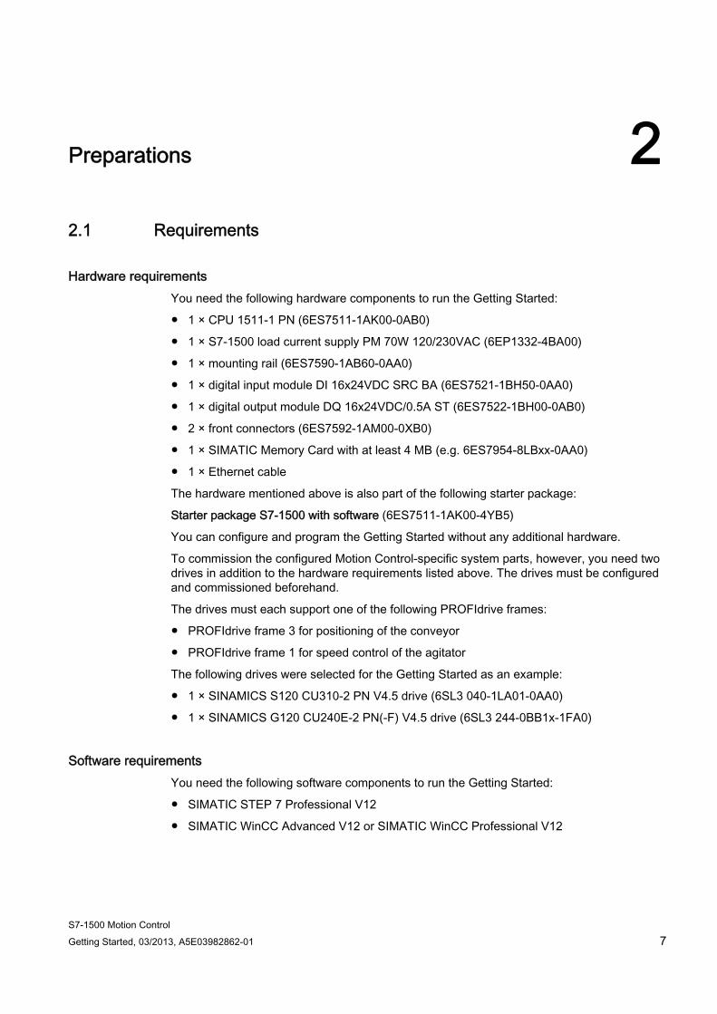
Hardware requirements You need the following hardware components to run the Getting Started:
● 1 × CPU 1511-1 PN (6ES7511-1AK00-0AB0)
● 1 × S7-1500 load current supply PM 70W 120/230VAC (6EP1332-4BA00)
● 1 × mounting rail (6ES7590-1AB60-0AA0)
● 1 × digital input module DI 16x24VDC SRC BA (6ES7521-1BH50-0AA0)
● 1 × digital output module DQ 16x24VDC/0.5A ST (6ES7522-1BH00-0AB0)
● 2 × front connectors (6ES7592-1AM00-0XB0)
● 1 × SIMATIC Memory Card with at least 4 MB (e.g. 6ES7954-8LBxx-0AA0)
● 1 × Ethernet cable
The hardware mentioned above is also part of the following starter package:
Starter package S7-1500 with software (6ES7511-1AK00-4YB5)
You can configure and program the Getting Started without any additional hardware.
To commission the configured Motion Control-specific system parts, however, you need two drives in addition to the hardware requirements listed above. The drives must be configured and commissioned beforehand.
The drives must each support one of the following PROFIdrive frames:
● PROFIdrive frame 3 for positioning of the conveyor
● PROFIdrive frame 1 for speed control of the agitator
The following drives were selected for the Getting Started as an example:
● 1 × SINAMICS S120 CU310-2 PN V4.5 drive (6SL3 040-1LA01-0AA0)
● 1 × SINAMICS G120 CU240E-2 PN(-F) V4.5 drive (6SL3 244-0BB1x-1FA0)
Software requirements You need the following software components to run the Getting Started:
● SIMATIC STEP 7 Professional V12
● SIMATIC WinCC Advanced V12 or SIMATIC WinCC Professional V12
Preparations 2.2 Basic procedure
S7-1500 Motion Control 8 Getting Started, 03/2013, A5E03982862-01
Sample project You need the following project files to run the Getting Started:
● Sample project "Color_Filling_Station"
● Library "MotionLib_Color_Filling_Station"
The project and the library are available as ZIP file under "Getting Started S7-1500 / TIA V12 (http://www.automation.siemens.com/salesmaterial-as/interactive-manuals/getting-started_simatic-s7-1500/project/color_filling_station_mc.zip)".
2.2 Basic procedure Starting with the sample project "Color_Filling_Station", configure the drives and technology objects with the TIA Portal. Then you create a STEP 7 user program that allows you to control the movement of the drives.
The procedure is divided into the following basic steps:
● Configuring drives
● Creating technology objects
● Programming the PLC
● Testing a function

Preparations 2.3 Opening a project
S7-1500 Motion Control Getting Started, 03/2013, A5E03982862-01 9
2.3 Opening a project The included sample project "Color_Filling_Station" is the starting point for further action. Open the project in the project view.
Preparations 2.4 Swapping the start screen
S7-1500 Motion Control 10 Getting Started, 03/2013, A5E03982862-01
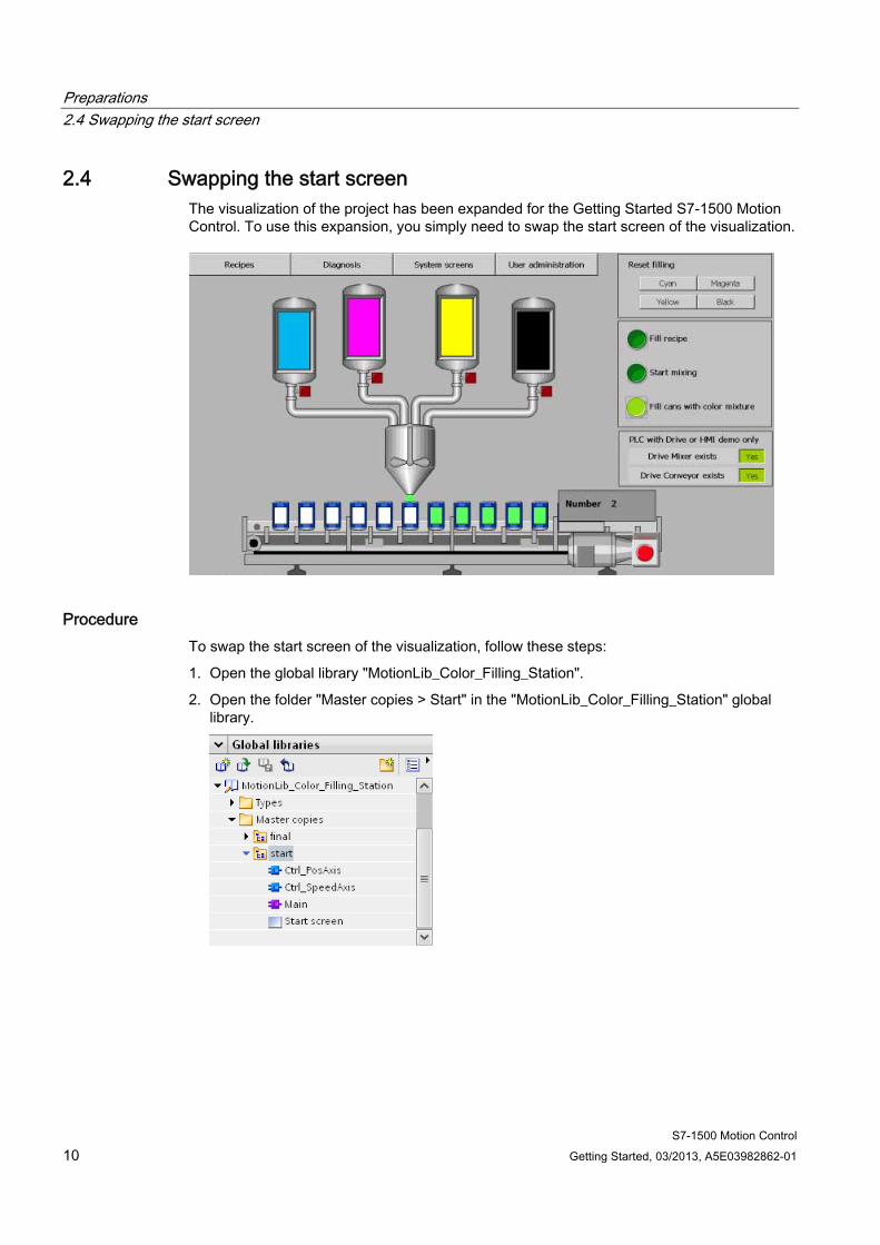
2.4 Swapping the start screen The visualization of the project has been expanded for the Getting Started S7-1500 Motion Control. To use this expansion, you simply need to swap the start screen of the visualization.
Procedure To swap the start screen of the visualization, follow these steps:
1. Open the global library "MotionLib_Color_Filling_Station".
2. Open the folder "Master copies > Start" in the "MotionLib_Color_Filling_Station" global library.
Preparations 2.4 Swapping the start screen
S7-1500 Motion Control Getting Started, 03/2013, A5E03982862-01 11
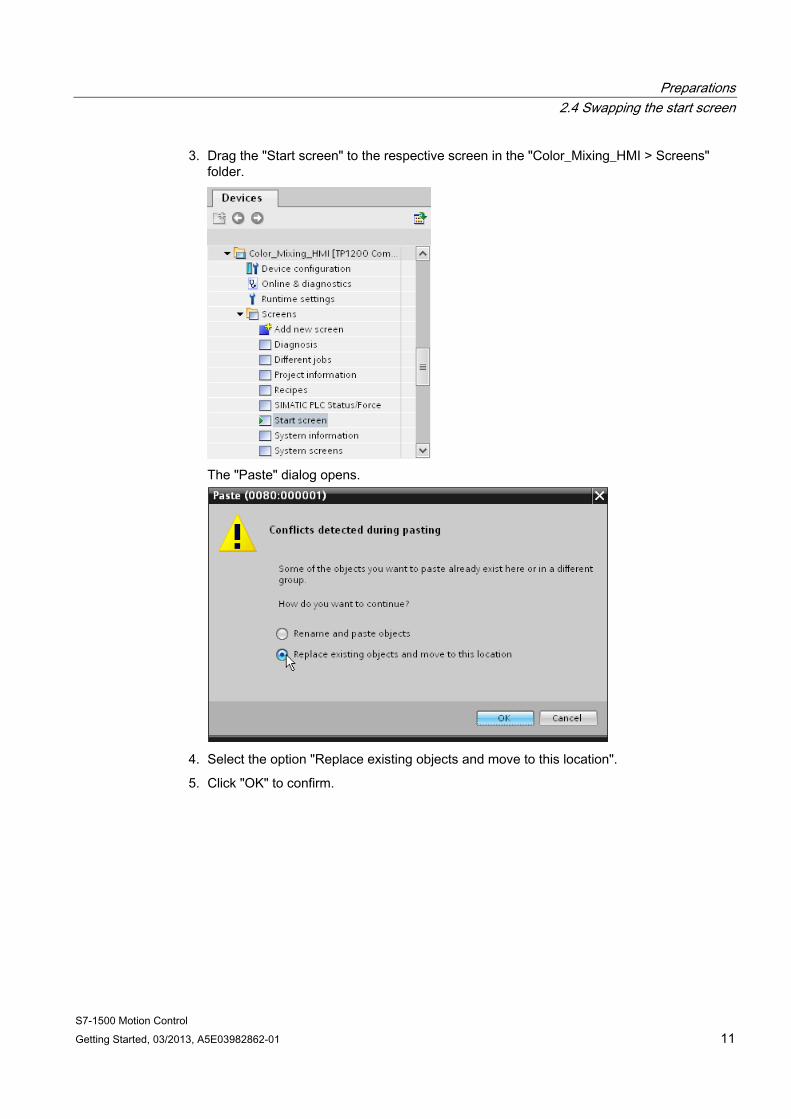
3. Drag the "Start screen" to the respective screen in the "Color_Mixing_HMI > Screens" folder.
The "Paste" dialog opens.
4. Select the option "Replace existing objects and move to this location".
5. Click "OK" to confirm.
Preparations 2.4 Swapping the start screen
S7-1500 Motion Control 12 Getting Started, 03/2013, A5E03982862-01
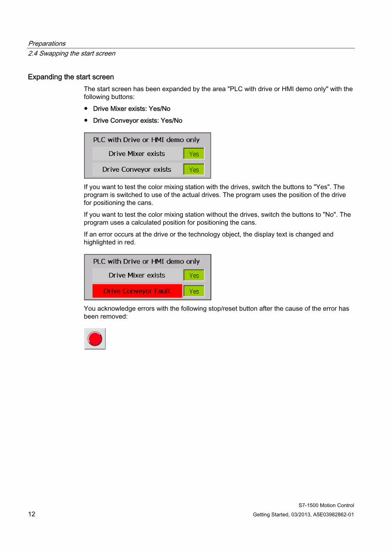
Expanding the start screen The start screen has been expanded by the area "PLC with drive or HMI demo only" with the following buttons:
● Drive Mixer exists: Yes/No
● Drive Conveyor exists: Yes/No
If you want to test the color mixing station with the drives, switch the buttons to "Yes". The program is switched to use of the actual drives. The program uses the position of the drive for positioning the cans.
If you want to test the color mixing station without the drives, switch the buttons to "No". The program uses a calculated position for positioning the cans.
If an error occurs at the drive or the technology object, the display text is changed and highlighted in red.
You acknowledge errors with the following stop/reset button after the cause of the error has been removed:

Preparations 2.5 Pasting blocks
S7-1500 Motion Control Getting Started, 03/2013, A5E03982862-01 13
2.5 Pasting blocks The following program blocks have been prepared to simplify the step sequences and avoid repetitions:
● Organization block "Main"
● Function block "Ctrl_PosAxis"
● Function block "Ctrl_SpeedAxis"
You only have to copy these program blocks from the global library into the project.
Procedure To copy the program blocks into the project, follow these steps:
1. Open the "Color_Mixing_CPU > Program blocks" folder in the project tree.
2. Open the folder "Master copies > Start" in the "MotionLib_Color_Filling_Station" global library.
3. Drag-and-drop the "Main" organization block to the corresponding block in the "Program blocks" folder.
The "Paste" dialog opens.
4. Select the option "Replace existing objects and move to this location".
5. Click "OK" to confirm.
6. Drag-and-drop the "Ctrl_PosAxis" and "Ctrl_SpeedAxis" function blocks to the "Program blocks" folder.

Preparations 2.5 Pasting blocks
S7-1500 Motion Control 14 Getting Started, 03/2013, A5E03982862-01
S7-1500 Motion Control Getting Started, 03/2013, A5E03982862-01 15
Configuring drives 33.1 Configuring SINAMICS S120
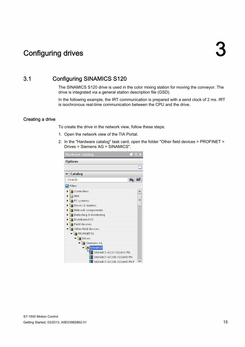
The SINAMICS S120 drive is used in the color mixing station for moving the conveyor. The drive is integrated via a general station description file (GSD).
In the following example, the IRT communication is prepared with a send clock of 2 ms. IRT is isochronous real-time communication between the CPU and the drive.
Creating a drive To create the drive in the network view, follow these steps:
1. Open the network view of the TIA Portal.
2. In the "Hardware catalog" task card, open the folder "Other field devices > PROFINET > Drives > Siemens AG > SINAMICS".

Configuring drives 3.1 Configuring SINAMICS S120
S7-1500 Motion Control 16 Getting Started, 03/2013, A5E03982862-01
3. Select the drive "SINAMICS S120 CU310-2 PN V4.5".
4. Drag-and-drop the drive into the network view.
The drive is inserted in the network view.
Configuring drives 3.1 Configuring SINAMICS S120
S7-1500 Motion Control Getting Started, 03/2013, A5E03982862-01 17
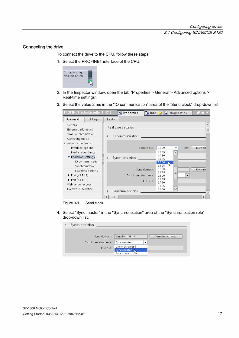
Connecting the drive To connect the drive to the CPU, follow these steps:
1. Select the PROFINET interface of the CPU.
2. In the Inspector window, open the tab "Properties > General > Advanced options >
Real-time settings".
3. Select the value 2 ms in the "IO communication" area of the "Send clock" drop-down list.
Figure 3-1 Send clock
4. Select "Sync master" in the "Synchronization" area of the "Synchronization role" drop-down list.
Configuring drives 3.1 Configuring SINAMICS S120
S7-1500 Motion Control 18 Getting Started, 03/2013, A5E03982862-01
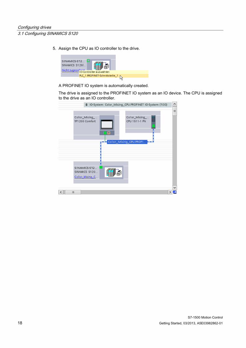
5. Assign the CPU as IO controller to the drive.
A PROFINET IO system is automatically created.
The drive is assigned to the PROFINET IO system as an IO device. The CPU is assigned to the drive as an IO controller.
Configuring drives 3.1 Configuring SINAMICS S120
S7-1500 Motion Control Getting Started, 03/2013, A5E03982862-01 19
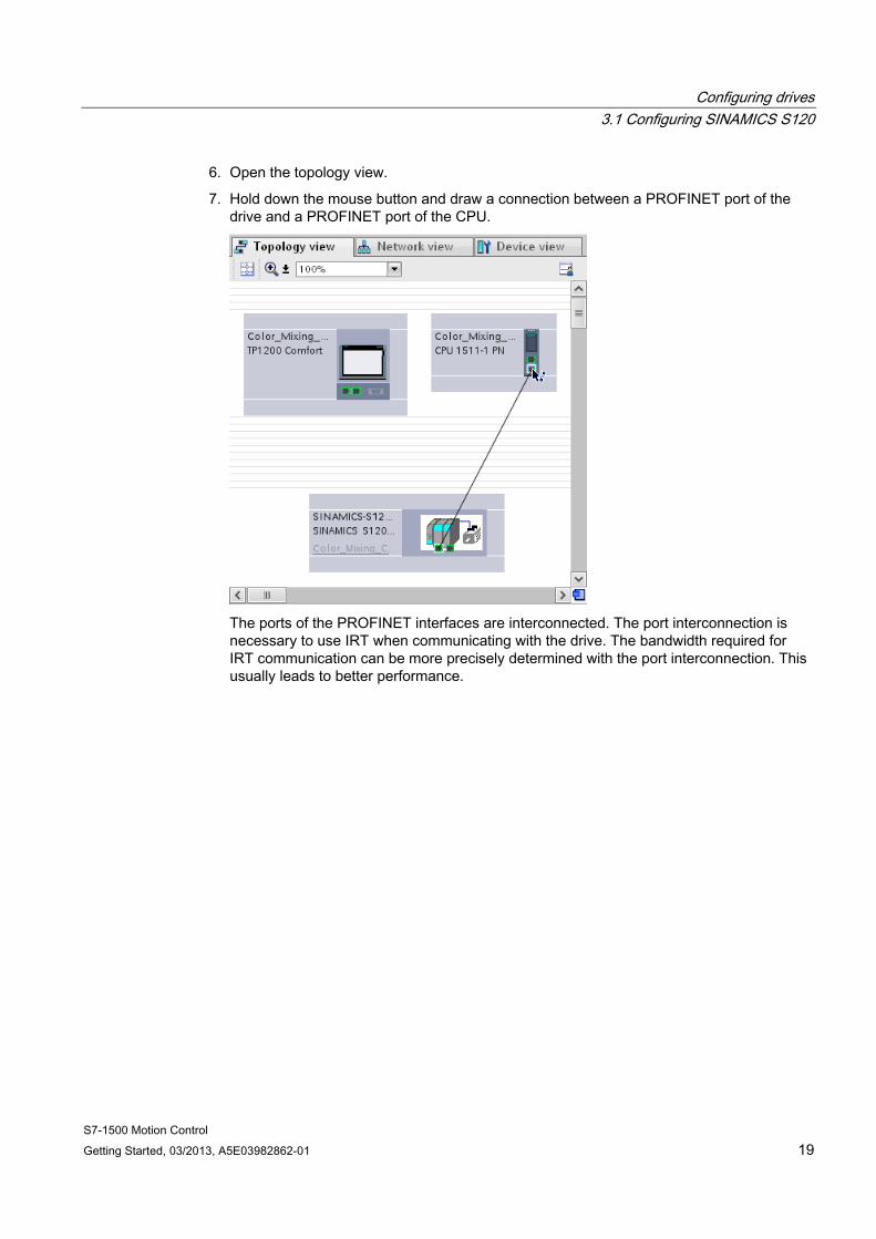
6. Open the topology view.
7. Hold down the mouse button and draw a connection between a PROFINET port of the drive and a PROFINET port of the CPU.
The ports of the PROFINET interfaces are interconnected. The port interconnection is necessary to use IRT when communicating with the drive. The bandwidth required for IRT communication can be more precisely determined with the port interconnection. This usually leads to better performance.
Configuring drives 3.1 Configuring SINAMICS S120
S7-1500 Motion Control 20 Getting Started, 03/2013, A5E03982862-01
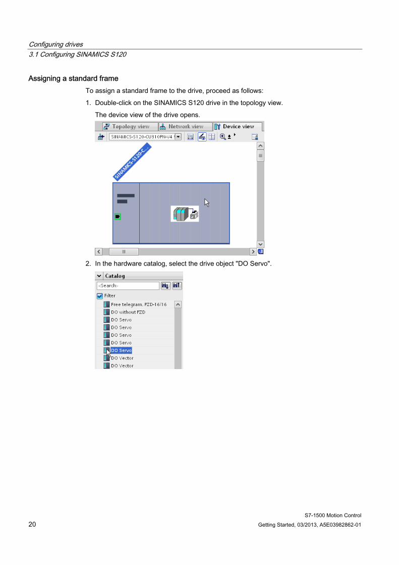
Assigning a standard frame To assign a standard frame to the drive, proceed as follows:
1. Double-click on the SINAMICS S120 drive in the topology view.
The device view of the drive opens.
2. In the hardware catalog, select the drive object "DO Servo".
Configuring drives 3.1 Configuring SINAMICS S120
S7-1500 Motion Control Getting Started, 03/2013, A5E03982862-01 21
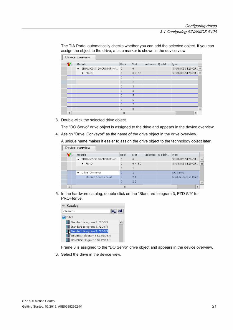
The TIA Portal automatically checks whether you can add the selected object. If you can assign the object to the drive, a blue marker is shown in the device view.
3. Double-click the selected drive object.
The "DO Servo" drive object is assigned to the drive and appears in the device overview.
4. Assign "Drive_Conveyor" as the name of the drive object in the drive overview.
A unique name makes it easier to assign the drive object to the technology object later.
5. In the hardware catalog, double-click on the "Standard telegram 3, PZD-5/9" for
PROFIdrive.
Frame 3 is assigned to the "DO Servo" drive object and appears in the device overview.
6. Select the drive in the device view.
Configuring drives 3.1 Configuring SINAMICS S120
S7-1500 Motion Control 22 Getting Started, 03/2013, A5E03982862-01
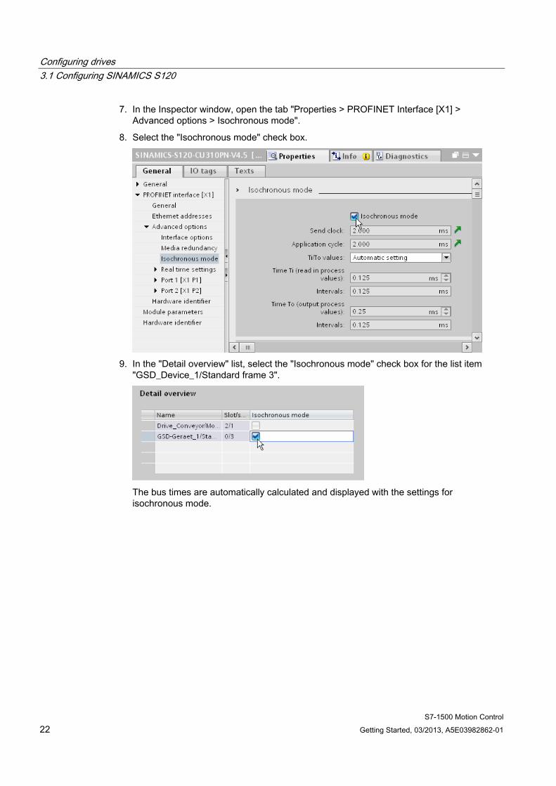
7. In the Inspector window, open the tab "Properties > PROFINET Interface [X1] > Advanced options > Isochronous mode".
8. Select the "Isochronous mode" check box.
9. In the "Detail overview" list, select the "Isochronous mode" check box for the list item
"GSD_Device_1/Standard frame 3".
The bus times are automatically calculated and displayed with the settings for isochronous mode.
Configuring drives 3.2 Configuring SINAMICS G120
S7-1500 Motion Control Getting Started, 03/2013, A5E03982862-01 23
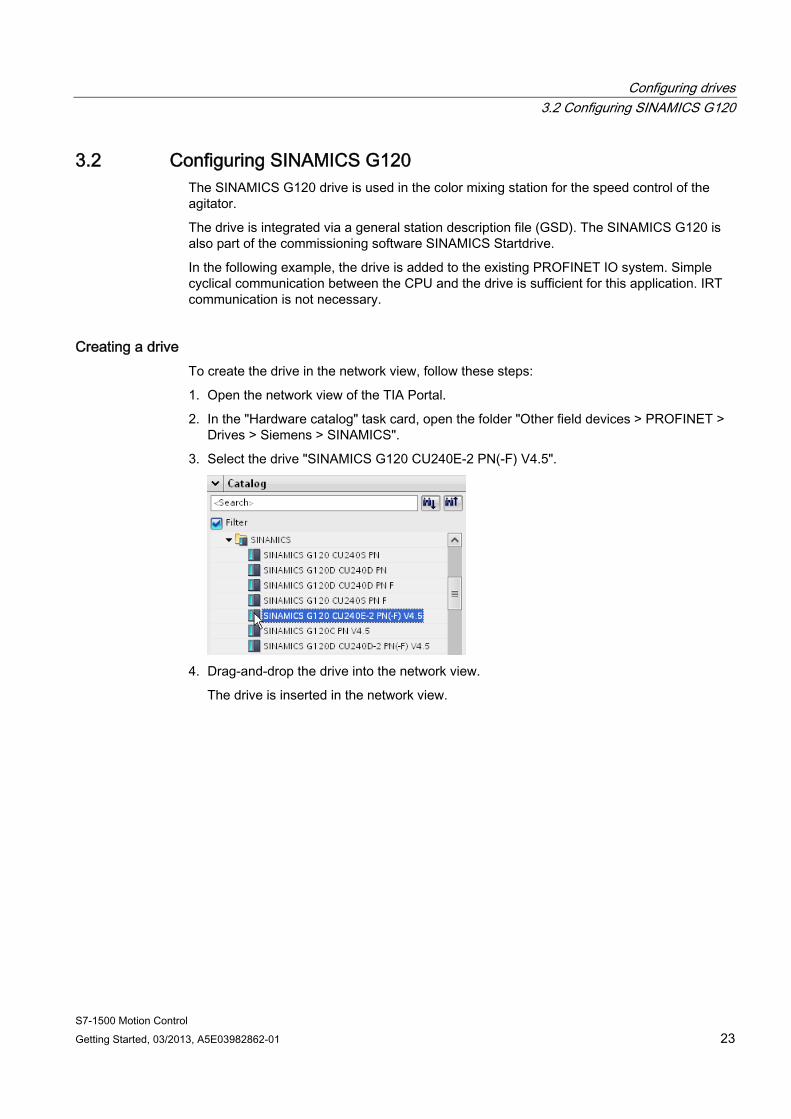
3.2 Configuring SINAMICS G120 The SINAMICS G120 drive is used in the color mixing station for the speed control of the agitator.
The drive is integrated via a general station description file (GSD). The SINAMICS G120 is also part of the commissioning software SINAMICS Startdrive.
In the following example, the drive is added to the existing PROFINET IO system. Simple cyclical communication between the CPU and the drive is sufficient for this application. IRT communication is not necessary.
Creating a drive To create the drive in the network view, follow these steps:
1. Open the network view of the TIA Portal.
2. In the "Hardware catalog" task card, open the folder "Other field devices > PROFINET > Drives > Siemens > SINAMICS".
3. Select the drive "SINAMICS G120 CU240E-2 PN(-F) V4.5".
4. Drag-and-drop the drive into the network view.
The drive is inserted in the network view.

Configuring drives 3.2 Configuring SINAMICS G120
S7-1500 Motion Control 24 Getting Started, 03/2013, A5E03982862-01
Connecting the drive to the network To connect the drive to the CPU, follow these steps:
1. Assign the CPU as IO controller to the drive.
The drive is assigned to the PROFINET IO system as an IO device. The CPU is assigned to the drive as an IO controller.
Configuring drives 3.2 Configuring SINAMICS G120
S7-1500 Motion Control Getting Started, 03/2013, A5E03982862-01 25
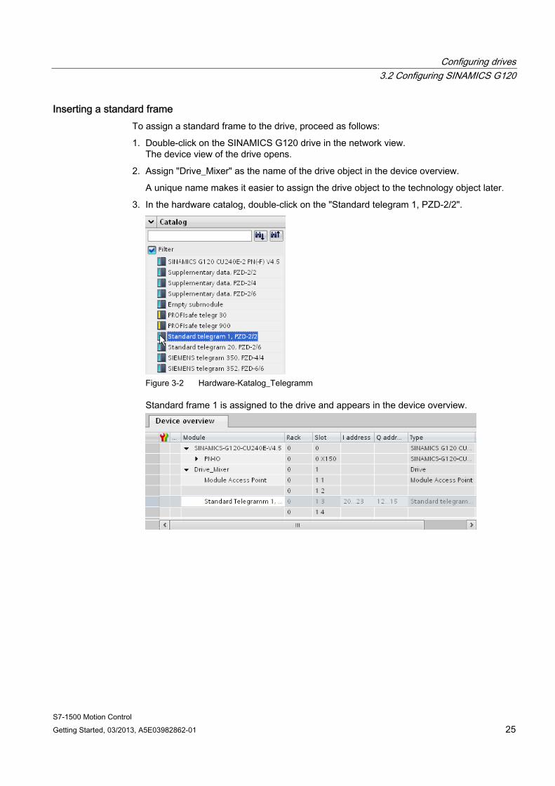
Inserting a standard frame To assign a standard frame to the drive, proceed as follows:
1. Double-click on the SINAMICS G120 drive in the network view. The device view of the drive opens.
2. Assign "Drive_Mixer" as the name of the drive object in the device overview.
A unique name makes it easier to assign the drive object to the technology object later.
3. In the hardware catalog, double-click on the "Standard telegram 1, PZD-2/2".
Figure 3-2 Hardware-Katalog_Telegramm
Standard frame 1 is assigned to the drive and appears in the device overview.
Configuring drives 3.3 Using prepared drives
S7-1500 Motion Control 26 Getting Started, 03/2013, A5E03982862-01
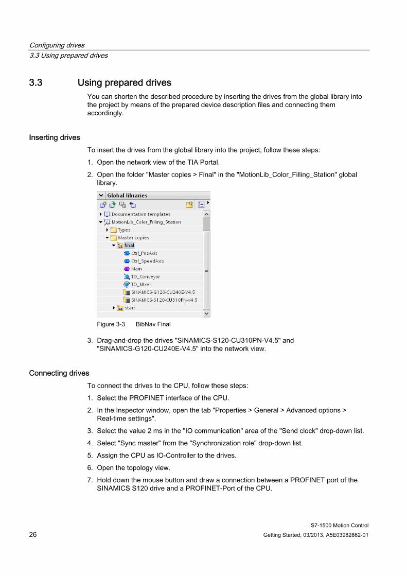
3.3 Using prepared drives You can shorten the described procedure by inserting the drives from the global library into the project by means of the prepared device description files and connecting them accordingly.
Inserting drives To insert the drives from the global library into the project, follow these steps:
1. Open the network view of the TIA Portal.
2. Open the folder "Master copies > Final" in the "MotionLib_Color_Filling_Station" global library.
Figure 3-3 BibNav Final
3. Drag-and-drop the drives "SINAMICS-S120-CU310PN-V4.5" and "SINAMICS-G120-CU240E-V4.5" into the network view.
Connecting drives To connect the drives to the CPU, follow these steps:
1. Select the PROFINET interface of the CPU.
2. In the Inspector window, open the tab "Properties > General > Advanced options > Real-time settings".
3. Select the value 2 ms in the "IO communication" area of the "Send clock" drop-down list.
4. Select "Sync master" from the "Synchronization role" drop-down list.
5. Assign the CPU as IO-Controller to the drives.
6. Open the topology view.
7. Hold down the mouse button and draw a connection between a PROFINET port of the SINAMICS S120 drive and a PROFINET-Port of the CPU.
S7-1500 Motion Control Getting Started, 03/2013, A5E03982862-01 27
Creating technology objects 44.1 Configuring the positioning axis
The positioning axis technology object enables the position-controlled positioning of a drive. You can assign positioning jobs for the conveyor with Motion Control instructions in your user program.
In the following example, you create a positioning axis technology object and assign it to the previously configured SINAMICS S120 drive. You assign the drive interface with PROFIdrive frame 3. The properties of the drive interface are set automatically with this step.
The organization blocks "MC-Servo" and "MC-Interpolator" are automatically created in the project when you create the technology object.
Creating technology objects 4.1 Configuring the positioning axis
S7-1500 Motion Control 28 Getting Started, 03/2013, A5E03982862-01
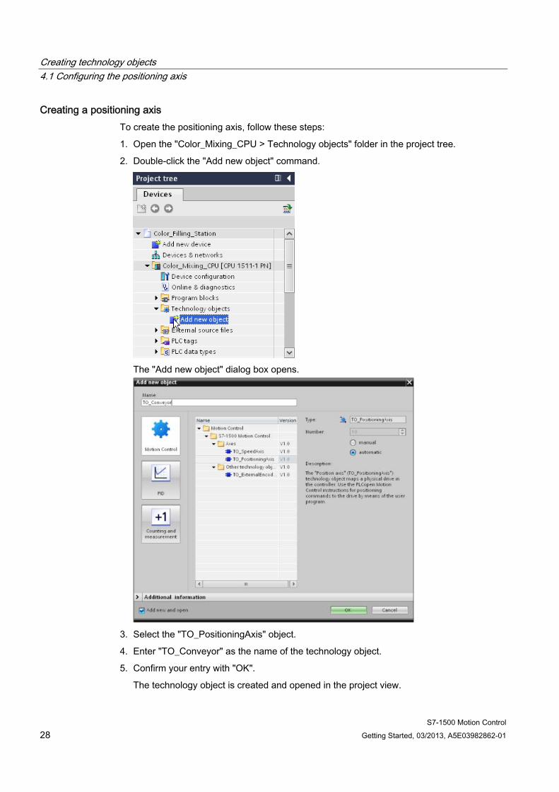
Creating a positioning axis To create the positioning axis, follow these steps:
1. Open the "Color_Mixing_CPU > Technology objects" folder in the project tree.
2. Double-click the "Add new object" command.
The "Add new object" dialog box opens.
3. Select the "TO_PositioningAxis" object.
4. Enter "TO_Conveyor" as the name of the technology object.
5. Confirm your entry with "OK".
The technology object is created and opened in the project view.
Creating technology objects 4.1 Configuring the positioning axis
S7-1500 Motion Control Getting Started, 03/2013, A5E03982862-01 29
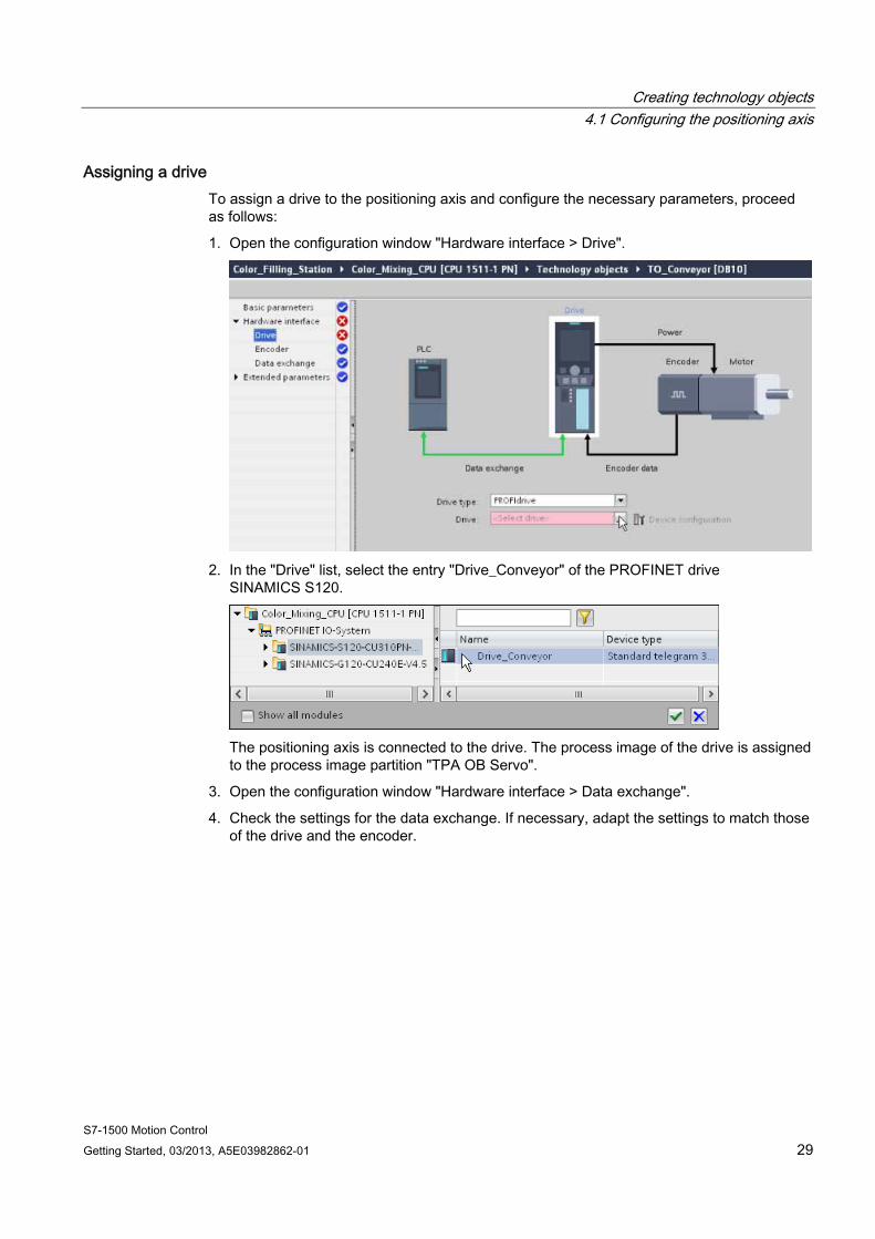
Assigning a drive To assign a drive to the positioning axis and configure the necessary parameters, proceed as follows:
1. Open the configuration window "Hardware interface > Drive".
2. In the "Drive" list, select the entry "Drive_Conveyor" of the PROFINET drive
SINAMICS S120.
The positioning axis is connected to the drive. The process image of the drive is assigned to the process image partition "TPA OB Servo".
3. Open the configuration window "Hardware interface > Data exchange".
4. Check the settings for the data exchange. If necessary, adapt the settings to match those of the drive and the encoder.

Creating technology objects 4.1 Configuring the positioning axis
S7-1500 Motion Control 30 Getting Started, 03/2013, A5E03982862-01
Configuring Modulo To configure the Modulo settings, follow these steps:
1. Open the configuration window "Basic parameters".
2. Select the "Enable Modulo" check box.
3. Enter the value 0.0 mm in the "Start value" box.
4. Enter the value 54.0 mm in the "Modulo length" box.
You can use the default values for the extended parameters in this example.
Creating technology objects 4.2 Configuring a speed axis
S7-1500 Motion Control Getting Started, 03/2013, A5E03982862-01 31
4.2 Configuring a speed axis The speed axis technology object enables you to specify the speed for a drive. You can assign motion jobs for the agitator with Motion Control instructions in your user program.
In the following example, you create a speed axis technology object and assign it to the previously configured SINAMICS G120 drive. You assign the drive interface with PROFIdrive frame 1. The properties of the drive interface are set automatically with this step.
The organization blocks "MC-Servo" and "MC-Interpolator" were already created when you created the positioning axis.
Creating a speed axis To create the speed axis, follow these steps:
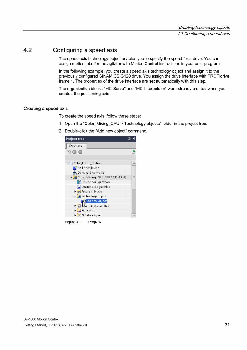
1. Open the "Color_Mixing_CPU > Technology objects" folder in the project tree.
2. Double-click the "Add new object" command.
Figure 4-1 ProjNav
Creating technology objects 4.2 Configuring a speed axis
S7-1500 Motion Control 32 Getting Started, 03/2013, A5E03982862-01
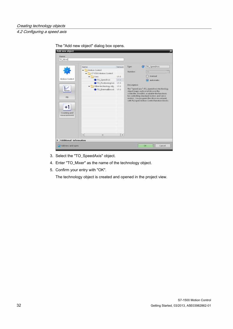
The "Add new object" dialog box opens.
3. Select the "TO_SpeedAxis" object.
4. Enter "TO_Mixer" as the name of the technology object.
5. Confirm your entry with "OK".
The technology object is created and opened in the project view.
Creating technology objects 4.2 Configuring a speed axis
S7-1500 Motion Control Getting Started, 03/2013, A5E03982862-01 33
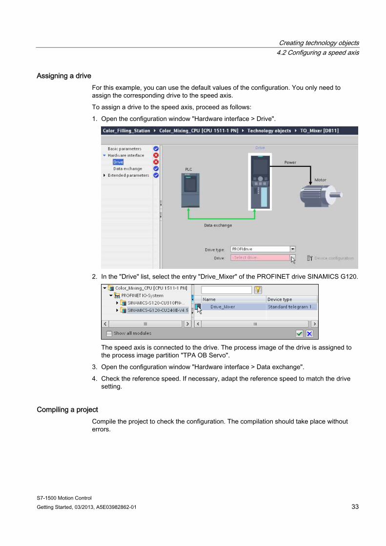
Assigning a drive For this example, you can use the default values of the configuration. You only need to assign the corresponding drive to the speed axis.
To assign a drive to the speed axis, proceed as follows:
1. Open the configuration window "Hardware interface > Drive".
2. In the "Drive" list, select the entry "Drive_Mixer" of the PROFINET drive SINAMICS G120.
The speed axis is connected to the drive. The process image of the drive is assigned to the process image partition "TPA OB Servo".
3. Open the configuration window "Hardware interface > Data exchange".
4. Check the reference speed. If necessary, adapt the reference speed to match the drive setting.
Compiling a project Compile the project to check the configuration. The compilation should take place without errors.
Creating technology objects 4.3 Using prepared technology objects
S7-1500 Motion Control 34 Getting Started, 03/2013, A5E03982862-01
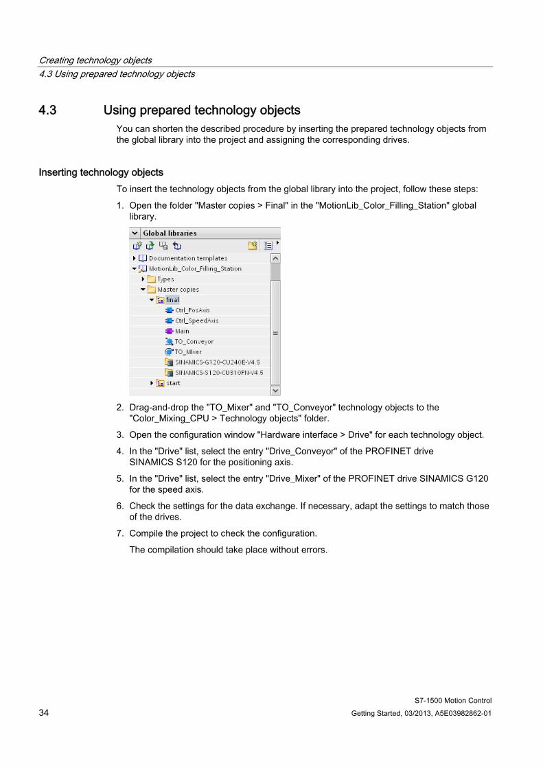
4.3 Using prepared technology objects You can shorten the described procedure by inserting the prepared technology objects from the global library into the project and assigning the corresponding drives.
Inserting technology objects To insert the technology objects from the global library into the project, follow these steps:
1. Open the folder "Master copies > Final" in the "MotionLib_Color_Filling_Station" global library.
2. Drag-and-drop the "TO_Mixer" and "TO_Conveyor" technology objects to the
"Color_Mixing_CPU > Technology objects" folder.
3. Open the configuration window "Hardware interface > Drive" for each technology object.
4. In the "Drive" list, select the entry "Drive_Conveyor" of the PROFINET drive SINAMICS S120 for the positioning axis.
5. In the "Drive" list, select the entry "Drive_Mixer" of the PROFINET drive SINAMICS G120 for the speed axis.
6. Check the settings for the data exchange. If necessary, adapt the settings to match those of the drives.
7. Compile the project to check the configuration.
The compilation should take place without errors.
S7-1500 Motion Control Getting Started, 03/2013, A5E03982862-01 35
Programming the PLC 55.1 Structure of the user program
In this example, the user program of the corresponding axis is created in a separate function block.
The required Motion Control instructions are inserted as instances into the function blocks. The function blocks are then called in the cyclic user program.
5.2 Adding Motion Control instructions
5.2.1 Adding Motion Control instructions for a positioning axis Insert the following Motion Control instructions in the "Ctrl_PosAxis" function block for the user program to control the positioning axis:
● MC_Power
● MC_Reset
The following Motion Control instructions have already been inserted and interconnected with the corresponding tags:
● MC_Home
● MC_MoveRelative
● MC_MoveAbsolute
A network for transfer of error messages is also already in place.
Programming the PLC 5.2 Adding Motion Control instructions
S7-1500 Motion Control 36 Getting Started, 03/2013, A5E03982862-01
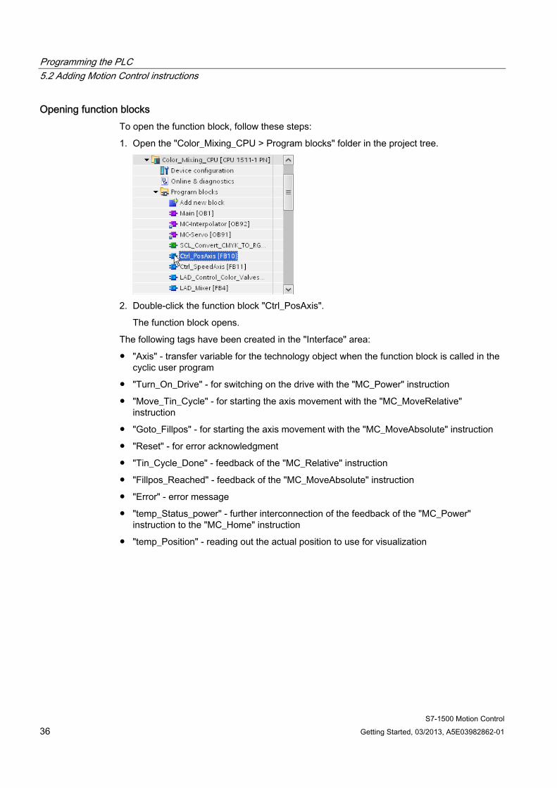
Opening function blocks To open the function block, follow these steps:
1. Open the "Color_Mixing_CPU > Program blocks" folder in the project tree.
2. Double-click the function block "Ctrl_PosAxis".
The function block opens.
The following tags have been created in the "Interface" area:
● "Axis" - transfer variable for the technology object when the function block is called in the cyclic user program
● "Turn_On_Drive" - for switching on the drive with the "MC_Power" instruction
● "Move_Tin_Cycle" - for starting the axis movement with the "MC_MoveRelative" instruction
● "Goto_Fillpos" - for starting the axis movement with the "MC_MoveAbsolute" instruction
● "Reset" - for error acknowledgment
● "Tin_Cycle_Done" - feedback of the "MC_Relative" instruction
● "Fillpos_Reached" - feedback of the "MC_MoveAbsolute" instruction
● "Error" - error message
● "temp_Status_power" - further interconnection of the feedback of the "MC_Power" instruction to the "MC_Home" instruction
● "temp_Position" - reading out the actual position to use for visualization

Programming the PLC 5.2 Adding Motion Control instructions
S7-1500 Motion Control Getting Started, 03/2013, A5E03982862-01 37
Inserting MC_Power To insert the Motion Control instruction "MC_Power" in the function block, follow these steps:
1. In the "Instructions" task card, open the "Technology > Motion Control > S7-1500 Motion Control" folder.
2. Insert the Motion Control instruction "MC_Power" into network 1 using drag-and-drop.

Programming the PLC 5.2 Adding Motion Control instructions
S7-1500 Motion Control 38 Getting Started, 03/2013, A5E03982862-01
The "Call options" dialog opens.
3. Click the "Multi instance" button.
4. Confirm your entry with "OK".
The Motion Control instruction "MC_Power" is added to network 1.
5. Drag-and-drop the "Axis" tag from the "Interface" area to the "Axis" parameter of the Motion Control instruction.
Programming the PLC 5.2 Adding Motion Control instructions
S7-1500 Motion Control Getting Started, 03/2013, A5E03982862-01 39
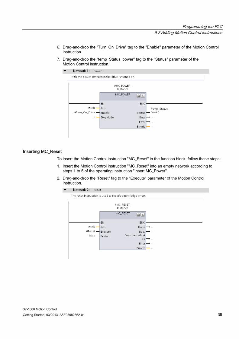
6. Drag-and-drop the "Turn_On_Drive" tag to the "Enable" parameter of the Motion Control instruction.
7. Drag-and-drop the "temp_Status_power" tag to the "Status" parameter of the Motion Control instruction.
Inserting MC_Reset To insert the Motion Control instruction "MC_Reset" in the function block, follow these steps:
1. Insert the Motion Control instruction "MC_Reset" into an empty network according to steps 1 to 5 of the operating instruction "Insert MC_Power".
2. Drag-and-drop the "Reset" tag to the "Execute" parameter of the Motion Control instruction.

Programming the PLC 5.2 Adding Motion Control instructions
S7-1500 Motion Control 40 Getting Started, 03/2013, A5E03982862-01
5.2.2 Adding Motion Control instructions for a speed axis Insert the following Motion Control instruction in the "Ctrl_SpeedAxis" function block for the user program to control the speed axis:
● MC_Power
● MC_Reset
The Motion Control instruction "MC_MoveVelocity" has already been inserted and linked with the corresponding tags.
A network for transfer of error messages is also already in place.
Opening function blocks To open the function block, follow these steps:
1. Open the "Color_Mixing_CPU > Program blocks" folder in the project tree.
2. Double-click the function block "Ctrl_SpeedAxis".
The function block opens.
The following tags have been created in the "Interface" area:
● "Axis" - transfer variable for the technology object when the function block is called in the cyclic user program
● "Start_Mixing" - for switching on the drive with the "MC_Power" instruction
● "Reset" - for error acknowledgment
● "Error" - error message
● "temp_Status_power" - further interconnection of the feedback of the "MC_Power" instruction to the "MC_MoveVelocity" instruction
Programming the PLC 5.2 Adding Motion Control instructions
S7-1500 Motion Control Getting Started, 03/2013, A5E03982862-01 41
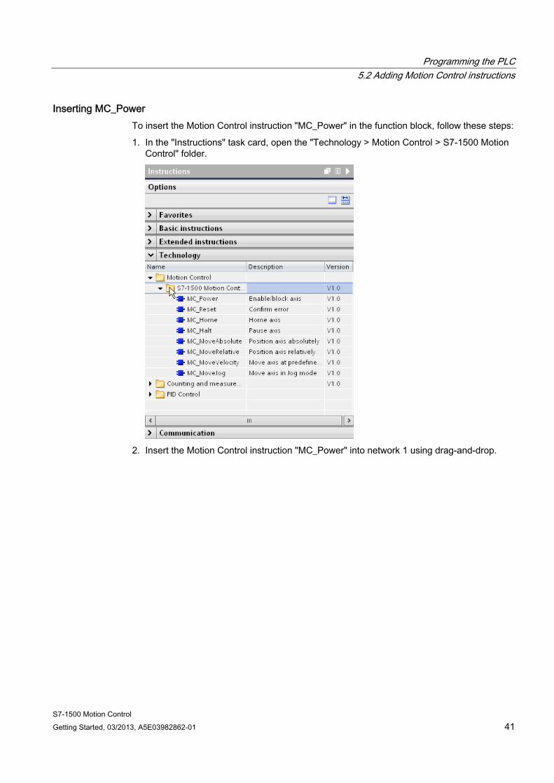
Inserting MC_Power To insert the Motion Control instruction "MC_Power" in the function block, follow these steps:
1. In the "Instructions" task card, open the "Technology > Motion Control > S7-1500 Motion Control" folder.
2. Insert the Motion Control instruction "MC_Power" into network 1 using drag-and-drop.
Programming the PLC 5.2 Adding Motion Control instructions
S7-1500 Motion Control 42 Getting Started, 03/2013, A5E03982862-01
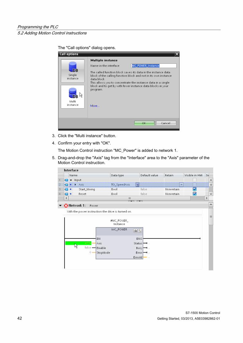
The "Call options" dialog opens.
3. Click the "Multi instance" button.
4. Confirm your entry with "OK".
The Motion Control instruction "MC_Power" is added to network 1.
5. Drag-and-drop the "Axis" tag from the "Interface" area to the "Axis" parameter of the Motion Control instruction.
Programming the PLC 5.2 Adding Motion Control instructions
S7-1500 Motion Control Getting Started, 03/2013, A5E03982862-01 43
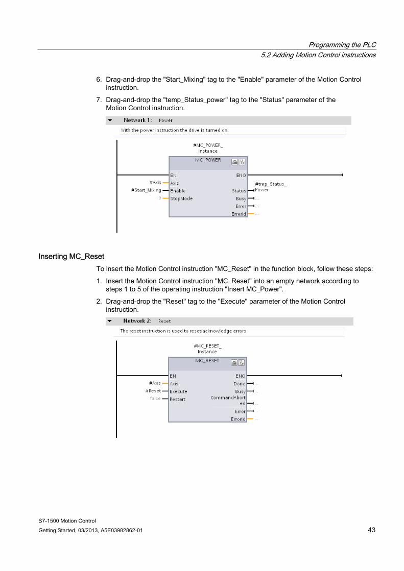
6. Drag-and-drop the "Start_Mixing" tag to the "Enable" parameter of the Motion Control instruction.
7. Drag-and-drop the "temp_Status_power" tag to the "Status" parameter of the Motion Control instruction.
Inserting MC_Reset To insert the Motion Control instruction "MC_Reset" in the function block, follow these steps:
1. Insert the Motion Control instruction "MC_Reset" into an empty network according to steps 1 to 5 of the operating instruction "Insert MC_Power".
2. Drag-and-drop the "Reset" tag to the "Execute" parameter of the Motion Control instruction.
Programming the PLC 5.2 Adding Motion Control instructions
S7-1500 Motion Control 44 Getting Started, 03/2013, A5E03982862-01
5.2.3 Using prepared function blocks You can shorten the described procedure by inserting the prepared function blocks from the global library into the project and interconnecting the corresponding tags.
Inserting function blocks To insert the function blocks from the global library into the project, follow these steps:
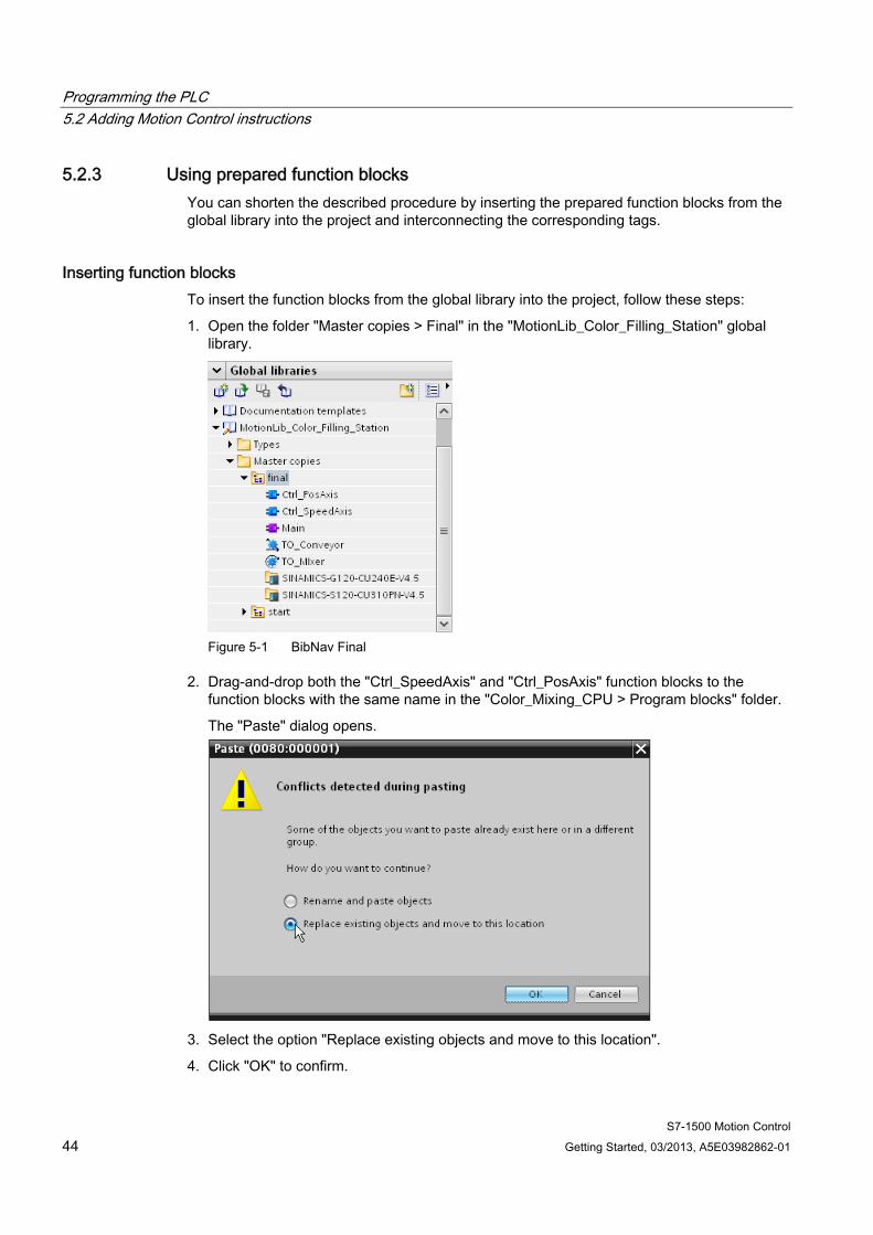
1. Open the folder "Master copies > Final" in the "MotionLib_Color_Filling_Station" global library.
Figure 5-1 BibNav Final
2. Drag-and-drop both the "Ctrl_SpeedAxis" and "Ctrl_PosAxis" function blocks to the function blocks with the same name in the "Color_Mixing_CPU > Program blocks" folder.
The "Paste" dialog opens.
3. Select the option "Replace existing objects and move to this location".
4. Click "OK" to confirm.
Programming the PLC 5.3 Integrating Motion Control instructions in the cyclic user program
S7-1500 Motion Control Getting Started, 03/2013, A5E03982862-01 45
5.3 Integrating Motion Control instructions in the cyclic user program
5.3.1 Integrating Motion Control instructions for a positioning axis The Motion Control instructions created to control the positioning axis are integrated in the cyclic user program through the corresponding function block. The function block is inserted into the "Main [OB1]" organization block and interconnected to the appropriate parameters.
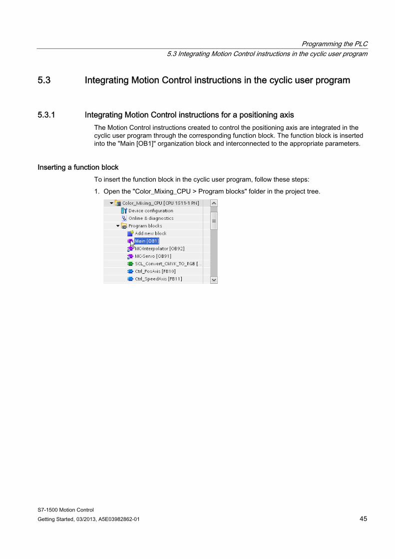
Inserting a function block To insert the function block in the cyclic user program, follow these steps:
1. Open the "Color_Mixing_CPU > Program blocks" folder in the project tree.
Programming the PLC 5.3 Integrating Motion Control instructions in the cyclic user program
S7-1500 Motion Control 46 Getting Started, 03/2013, A5E03982862-01
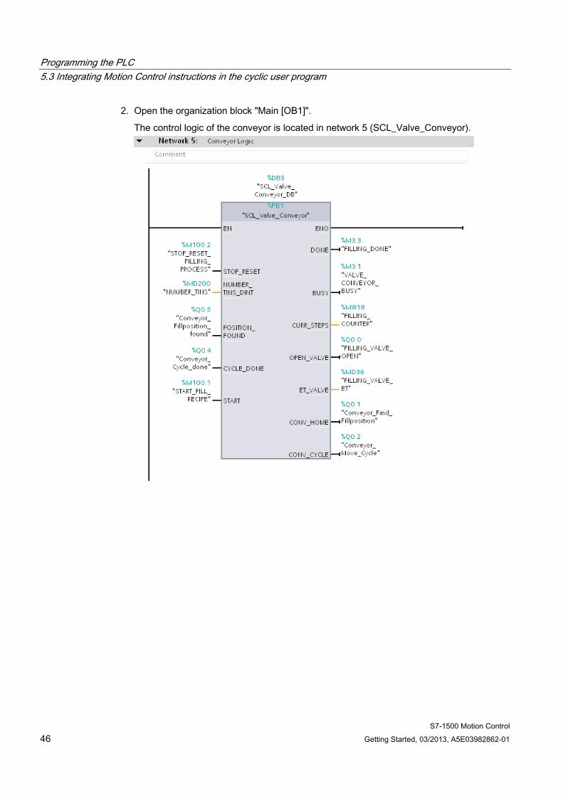
2. Open the organization block "Main [OB1]".
The control logic of the conveyor is located in network 5 (SCL_Valve_Conveyor).
Programming the PLC 5.3 Integrating Motion Control instructions in the cyclic user program
S7-1500 Motion Control Getting Started, 03/2013, A5E03982862-01 47
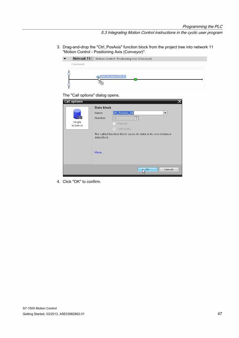
3. Drag-and-drop the "Ctrl_PosAxis" function block from the project tree into network 11 "Motion Control - Positioning Axis (Conveyor)".
The "Call options" dialog opens.
4. Click "OK" to confirm.
Programming the PLC 5.3 Integrating Motion Control instructions in the cyclic user program
S7-1500 Motion Control 48 Getting Started, 03/2013, A5E03982862-01
Interconnecting the function block To interconnect the function block with the appropriate parameters, follow these steps:
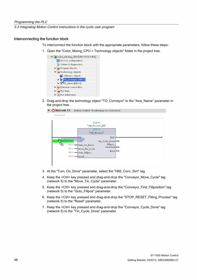
1. Open the "Color_Mixing_CPU > Technology objects" folder in the project tree.
2. Drag-and-drop the technology object "TO_Conveyor" to the "Axis_Name" parameter in
the project tree .
3. At the "Turn_On_Drive" parameter, select the "HMI_Conv_Sim" tag.
4. Keep the <Ctrl> key pressed and drag-and-drop the "Conveyor_Move_Cycle" tag (network 5) to the "Move_Tin_Cycle" parameter.
5. Keep the <Ctrl> key pressed and drag-and-drop the "Conveyor_Find_Fillposition" tag (network 5) to the "Goto_Fillpos" parameter.
6. Keep the <Ctrl> key pressed and drag-and-drop the "STOP_RESET_Filling_Process" tag (network 5) to the "Reset" parameter.
7. Keep the <Ctrl> key pressed and drag-and-drop the "Conveyor_Cycle_Done" tag (network 5) to the "Tin_Cycle_Done" parameter.
Programming the PLC 5.3 Integrating Motion Control instructions in the cyclic user program
S7-1500 Motion Control Getting Started, 03/2013, A5E03982862-01 49
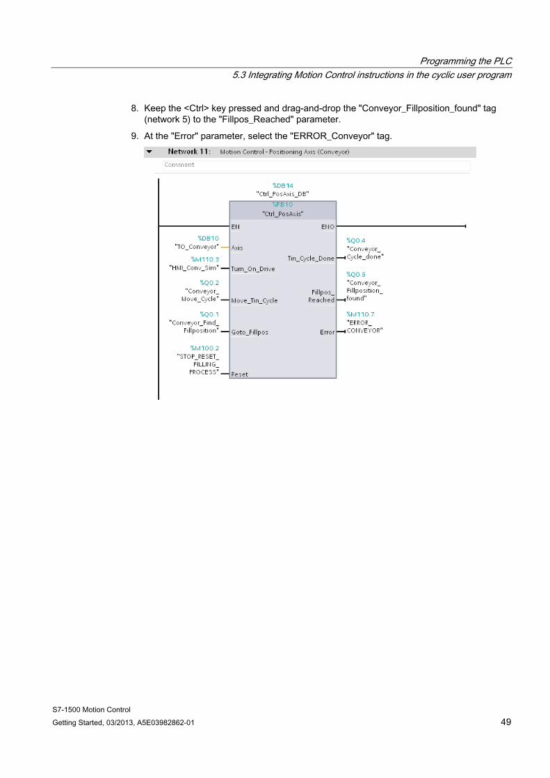
8. Keep the <Ctrl> key pressed and drag-and-drop the "Conveyor_Fillposition_found" tag (network 5) to the "Fillpos_Reached" parameter.
9. At the "Error" parameter, select the "ERROR_Conveyor" tag.

Programming the PLC 5.3 Integrating Motion Control instructions in the cyclic user program
S7-1500 Motion Control 50 Getting Started, 03/2013, A5E03982862-01
5.3.2 Integrating Motion Control instructions for a speed axis The Motion Control instructions used to control the speed axis are integrated in the cyclic user program through the corresponding function block. The function block is inserted into the "Main [OB1]" organization block and interconnected to the appropriate parameters.
Inserting a function block To insert the function block in the cyclic user program, follow these steps:
1. Open the "Color_Mixing_CPU > Program blocks" folder in the project tree.
2. Open the organization block "Main [OB1]".
The control logic of the agitator (LAD_Mixer) is located in network 4.
Programming the PLC 5.3 Integrating Motion Control instructions in the cyclic user program
S7-1500 Motion Control Getting Started, 03/2013, A5E03982862-01 51
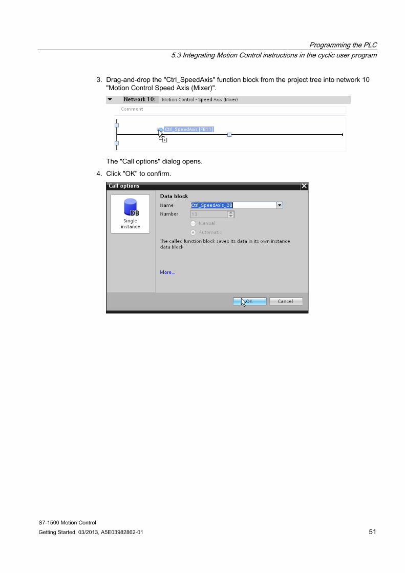
3. Drag-and-drop the "Ctrl_SpeedAxis" function block from the project tree into network 10 "Motion Control Speed Axis (Mixer)".
The "Call options" dialog opens.
4. Click "OK" to confirm.
Programming the PLC 5.3 Integrating Motion Control instructions in the cyclic user program
S7-1500 Motion Control 52 Getting Started, 03/2013, A5E03982862-01
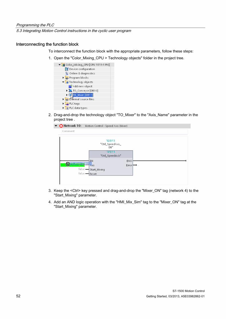
Interconnecting the function block To interconnect the function block with the appropriate parameters, follow these steps:
1. Open the "Color_Mixing_CPU > Technology objects" folder in the project tree.
2. Drag-and-drop the technology object "TO_Mixer" to the "Axis_Name" parameter in the
project tree .
3. Keep the <Ctrl> key pressed and drag-and-drop the "Mixer_ON" tag (network 4) to the
"Start_Mixing" parameter.
4. Add an AND logic operation with the "HMI_Mix_Sim" tag to the "Mixer_ON" tag at the "Start_Mixing" parameter.
Programming the PLC 5.3 Integrating Motion Control instructions in the cyclic user program
S7-1500 Motion Control Getting Started, 03/2013, A5E03982862-01 53
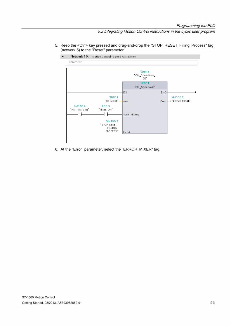
5. Keep the <Ctrl> key pressed and drag-and-drop the "STOP_RESET_Filling_Process" tag (network 5) to the "Reset" parameter.
6. At the "Error" parameter, select the "ERROR_MIXER" tag.
Programming the PLC 5.3 Integrating Motion Control instructions in the cyclic user program
S7-1500 Motion Control 54 Getting Started, 03/2013, A5E03982862-01
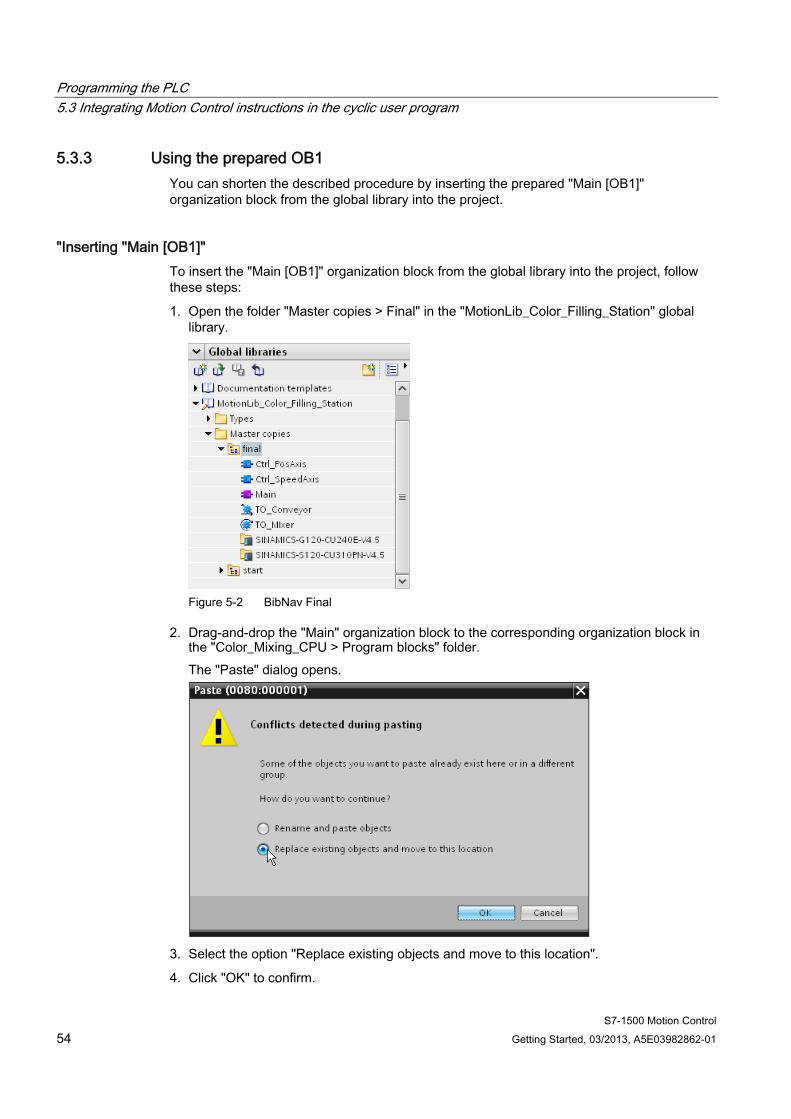
5.3.3 Using the prepared OB1 You can shorten the described procedure by inserting the prepared "Main [OB1]" organization block from the global library into the project.
"Inserting "Main [OB1]" To insert the "Main [OB1]" organization block from the global library into the project, follow these steps:
1. Open the folder "Master copies > Final" in the "MotionLib_Color_Filling_Station" global library.
Figure 5-2 BibNav Final
2. Drag-and-drop the "Main" organization block to the corresponding organization block in the "Color_Mixing_CPU > Program blocks" folder. The "Paste" dialog opens.
3. Select the option "Replace existing objects and move to this location".
4. Click "OK" to confirm.
Programming the PLC 5.4 Compiling and loading the project
S7-1500 Motion Control Getting Started, 03/2013, A5E03982862-01 55
5.4 Compiling and loading the project Compile the project and download it to the CPU to test the functions of the axes in the next step.

Programming the PLC 5.4 Compiling and loading the project
S7-1500 Motion Control 56 Getting Started, 03/2013, A5E03982862-01
S7-1500 Motion Control Getting Started, 03/2013, A5E03982862-01 57
Testing a function 66.1 "Positioning axis" axis control panel
You use the axis control panel and tuning for the function test and commissioning of the positioning axis to position the conveyor belt.
The procedure is divided into the following actions:
● Enabling the technology object
● Checking the direction of rotation
● Checking the distance evaluation
● Checking the velocity evaluation
● Optimizing gain
● Applying gain to project
● Evaluating errors
Requirement ● The drive has been commissioned and is ready for operation.
● The drive has been assigned a PROFINET device name.
Enabling the technology object To enable the positioning axis with the axis control panel, follow these steps:
1. Open the "Color_Mixing_CPU > Technology objects" folder in the project tree.
2. Open the commissioning window "Configuration > Extended parameters > Control loop" of the technology object "TO_Conveyor".
3. Enter the value 0.0 in the "Gain (Kv factor)" box.
You can compare the actual value and the setpoint of the velocity directly with each other if there is no gain of the control loop. Optimize the gain once you have checked the velocity evaluation and apply it to your project.
4. Download the program to the CPU.
Testing a function 6.1 "Positioning axis" axis control panel
S7-1500 Motion Control 58 Getting Started, 03/2013, A5E03982862-01
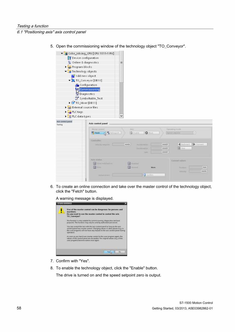
5. Open the commissioning window of the technology object "TO_Conveyor".
6. To create an online connection and take over the master control of the technology object,
click the "Fetch" button.
A warning message is displayed.
7. Confirm with "Yes".
8. To enable the technology object, click the "Enable" button.
The drive is turned on and the speed setpoint zero is output.
Testing a function 6.1 "Positioning axis" axis control panel
S7-1500 Motion Control Getting Started, 03/2013, A5E03982862-01 59
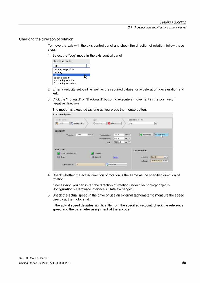
Checking the direction of rotation To move the axis with the axis control panel and check the direction of rotation, follow these steps:
1. Select the "Jog" mode in the axis control panel.
2. Enter a velocity setpoint as well as the required values for acceleration, deceleration and
jerk.
3. Click the "Forward" or "Backward" button to execute a movement in the positive or negative direction.
The motion is executed as long as you press the mouse button.
4. Check whether the actual direction of rotation is the same as the specified direction of
rotation.
If necessary, you can invert the direction of rotation under "Technology object > Configuration > Hardware interface > Data exchange".
5. Check the actual speed in the drive or use an external tachometer to measure the speed directly at the motor shaft.
If the actual speed deviates significantly from the specified setpoint, check the reference speed and the parameter assignment of the encoder.
Testing a function 6.1 "Positioning axis" axis control panel
S7-1500 Motion Control 60 Getting Started, 03/2013, A5E03982862-01
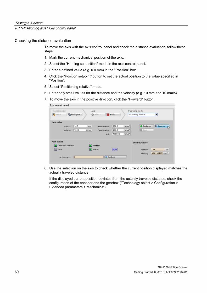
Checking the distance evaluation To move the axis with the axis control panel and check the distance evaluation, follow these steps:
1. Mark the current mechanical position of the axis.
2. Select the "Homing setposition" mode in the axis control panel.
3. Enter a defined value (e.g. 0.0 mm) in the "Position" box.
4. Click the "Position setpoint" button to set the actual position to the value specified in "Position".
5. Select "Positioning relative" mode.
6. Enter only small values for the distance and the velocity (e.g. 10 mm and 10 mm/s).
7. To move the axis in the positive direction, click the "Forward" button.
8. Use the selection on the axis to check whether the current position displayed matches the
actually traveled distance.
If the displayed current position deviates from the actually traveled distance, check the configuration of the encoder and the gearbox ("Technology object > Configuration > Extended parameters > Mechanics").
Testing a function 6.1 "Positioning axis" axis control panel
S7-1500 Motion Control Getting Started, 03/2013, A5E03982862-01 61
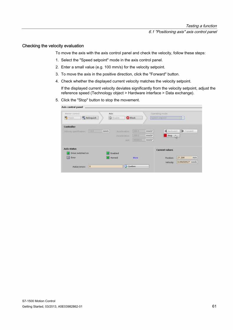
Checking the velocity evaluation To move the axis with the axis control panel and check the velocity, follow these steps:
1. Select the "Speed setpoint" mode in the axis control panel.
2. Enter a small value (e.g. 100 mm/s) for the velocity setpoint.
3. To move the axis in the positive direction, click the "Forward" button.
4. Check whether the displayed current velocity matches the velocity setpoint.
If the displayed current velocity deviates significantly from the velocity setpoint, adjust the reference speed (Technology object > Hardware interface > Data exchange).
5. Click the "Stop" button to stop the movement.
Testing a function 6.1 "Positioning axis" axis control panel
S7-1500 Motion Control 62 Getting Started, 03/2013, A5E03982862-01
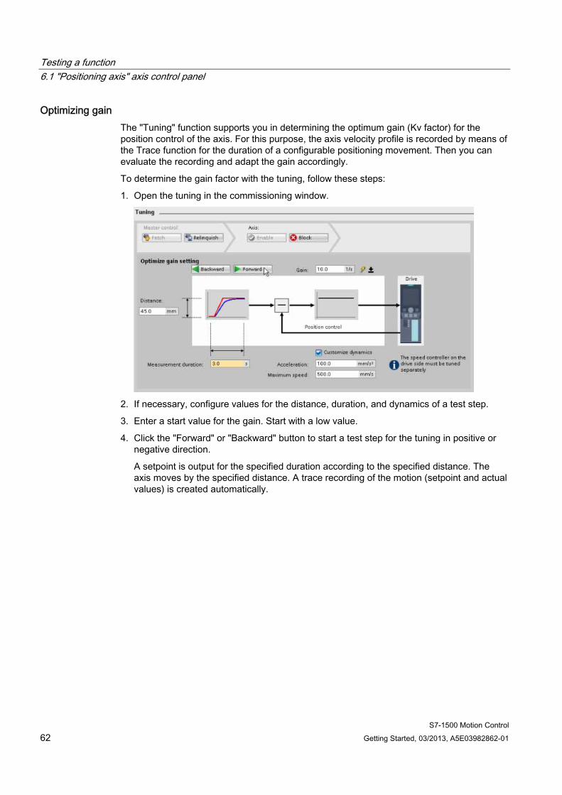
Optimizing gain The "Tuning" function supports you in determining the optimum gain (Kv factor) for the position control of the axis. For this purpose, the axis velocity profile is recorded by means of the Trace function for the duration of a configurable positioning movement. Then you can evaluate the recording and adapt the gain accordingly.
To determine the gain factor with the tuning, follow these steps:
1. Open the tuning in the commissioning window.
2. If necessary, configure values for the distance, duration, and dynamics of a test step.
3. Enter a start value for the gain. Start with a low value.
4. Click the "Forward" or "Backward" button to start a test step for the tuning in positive or negative direction.
A setpoint is output for the specified duration according to the specified distance. The axis moves by the specified distance. A trace recording of the motion (setpoint and actual values) is created automatically.
Testing a function 6.1 "Positioning axis" axis control panel
S7-1500 Motion Control Getting Started, 03/2013, A5E03982862-01 63
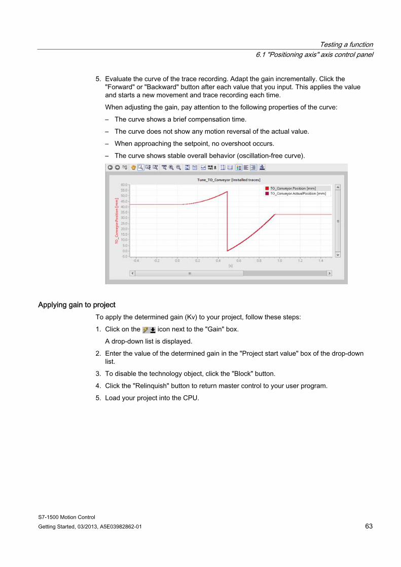
5. Evaluate the curve of the trace recording. Adapt the gain incrementally. Click the "Forward" or "Backward" button after each value that you input. This applies the value and starts a new movement and trace recording each time.
When adjusting the gain, pay attention to the following properties of the curve:
– The curve shows a brief compensation time.
– The curve does not show any motion reversal of the actual value.
– When approaching the setpoint, no overshoot occurs.
– The curve shows stable overall behavior (oscillation-free curve).
Applying gain to project To apply the determined gain (Kv) to your project, follow these steps:
1. Click on the icon next to the "Gain" box.
A drop-down list is displayed.
2. Enter the value of the determined gain in the "Project start value" box of the drop-down list.
3. To disable the technology object, click the "Block" button.
4. Click the "Relinquish" button to return master control to your user program.
5. Load your project into the CPU.
Testing a function 6.1 "Positioning axis" axis control panel
S7-1500 Motion Control 64 Getting Started, 03/2013, A5E03982862-01
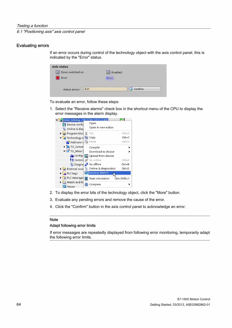
Evaluating errors If an error occurs during control of the technology object with the axis control panel, this is indicated by the "Error" status.
To evaluate an error, follow these steps:
1. Select the "Receive alarms" check box in the shortcut menu of the CPU to display the error messages in the alarm display.
2. To display the error bits of the technology object, click the "More" button.
3. Evaluate any pending errors and remove the cause of the error.
4. Click the "Confirm" button in the axis control panel to acknowledge an error.
Note Adapt following error limits
If error messages are repeatedly displayed from following error monitoring, temporarily adapt the following error limits.
Testing a function 6.2 "Speed axis" axis control panel
S7-1500 Motion Control Getting Started, 03/2013, A5E03982862-01 65
6.2 "Speed axis" axis control panel You use the axis control panel for the function test and commissioning of the speed axis to control the agitator.
The procedure is divided into the following actions:
● Enabling the technology object
● Moving and checking the axis
● Evaluating errors
Requirement ● The drive has been commissioned and is ready for operation.
● The drive has been assigned a PROFINET device name.
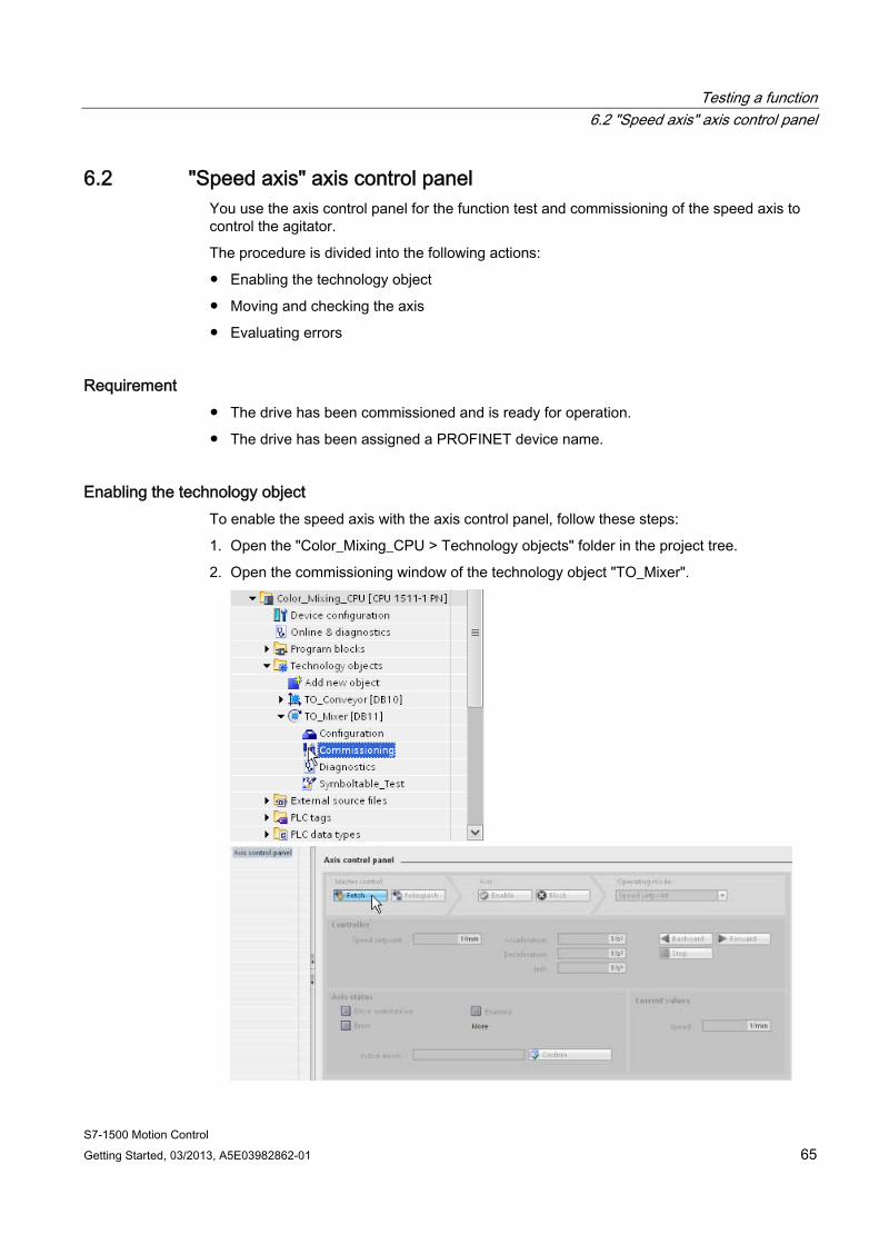
Enabling the technology object To enable the speed axis with the axis control panel, follow these steps:
1. Open the "Color_Mixing_CPU > Technology objects" folder in the project tree.
2. Open the commissioning window of the technology object "TO_Mixer".

Testing a function 6.2 "Speed axis" axis control panel
S7-1500 Motion Control 66 Getting Started, 03/2013, A5E03982862-01
3. To create an online connection and take over the master control of the technology object, click the "Fetch" button.
A warning message is displayed.
4. Confirm with "Yes".
5. To enable the technology object, click the "Enable" button.
The drive is turned on and the speed setpoint zero is output.
Testing a function 6.2 "Speed axis" axis control panel
S7-1500 Motion Control Getting Started, 03/2013, A5E03982862-01 67
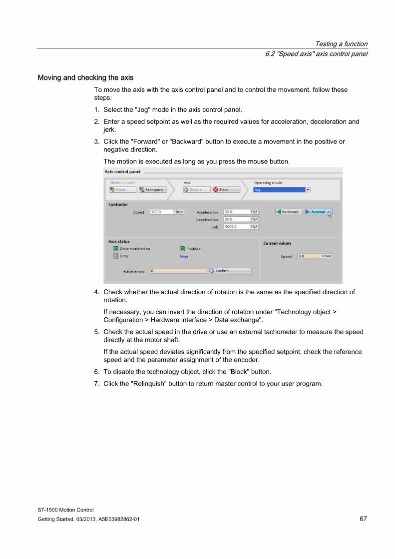
Moving and checking the axis To move the axis with the axis control panel and to control the movement, follow these steps:
1. Select the "Jog" mode in the axis control panel.
2. Enter a speed setpoint as well as the required values for acceleration, deceleration and jerk.
3. Click the "Forward" or "Backward" button to execute a movement in the positive or negative direction.
The motion is executed as long as you press the mouse button.
4. Check whether the actual direction of rotation is the same as the specified direction of
rotation.
If necessary, you can invert the direction of rotation under "Technology object > Configuration > Hardware interface > Data exchange".
5. Check the actual speed in the drive or use an external tachometer to measure the speed directly at the motor shaft.
If the actual speed deviates significantly from the specified setpoint, check the reference speed and the parameter assignment of the encoder.
6. To disable the technology object, click the "Block" button.
7. Click the "Relinquish" button to return master control to your user program.
Testing a function 6.2 "Speed axis" axis control panel
S7-1500 Motion Control 68 Getting Started, 03/2013, A5E03982862-01
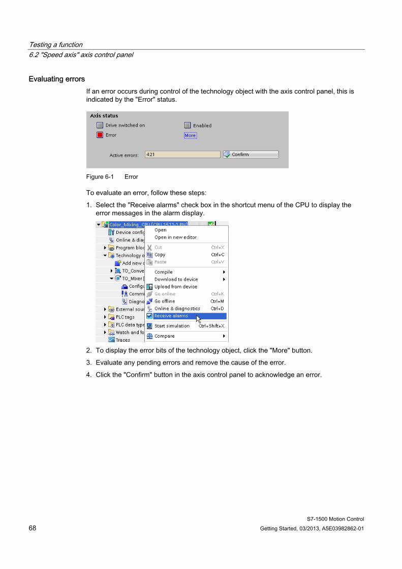
Evaluating errors If an error occurs during control of the technology object with the axis control panel, this is indicated by the "Error" status.
Figure 6-1 Error
To evaluate an error, follow these steps:
1. Select the "Receive alarms" check box in the shortcut menu of the CPU to display the error messages in the alarm display.
2. To display the error bits of the technology object, click the "More" button.
3. Evaluate any pending errors and remove the cause of the error.
4. Click the "Confirm" button in the axis control panel to acknowledge an error.

Testing a function 6.3 Testing the function in the start screen
S7-1500 Motion Control Getting Started, 03/2013, A5E03982862-01 69
6.3 Testing the function in the start screen You test the function of your user program by using the start screen of the visualization.
Procedure To test the function of your user program, follow these steps:
1. Save the project.
2. Download the program to the CPU.
3. Start the CPU.
4. Press the "Drive Mixer exists" button in the start screen of the project.
5. Press the "Start mixing" button in the start screen of the project.
The drive of the agitator is switched on by the Motion Control instruction "MC_Power".
When the technology object is enabled ("MC_Power.Status" = TRUE), a job is triggered with the Motion Control instruction "MC_MoveVelocity". The "MC_MoveVelocity" instruction specifies the configured speed (100 rpm). The technology object calculates speed setpoints and sends them to the drive. The drive executes the received setpoints and turns the agitator.
The release by the control program is revoked after 3 seconds. The drive is stopped and switched off.
You can change the speed by defining the "Velocity" parameter at the "MC_MoveVelocity" instruction. You can also adjust the dynamics in the configuration of the technology object under "Extended parameters > Dynamic default values".
Testing a function 6.3 Testing the function in the start screen
S7-1500 Motion Control 70 Getting Started, 03/2013, A5E03982862-01
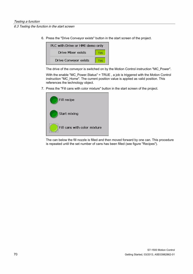
6. Press the "Drive Conveyor exists" button in the start screen of the project.
The drive of the conveyor is switched on by the Motion Control instruction "MC_Power".
With the enable "MC_Power.Status" = TRUE , a job is triggered with the Motion Control instruction "MC_Home". The current position value is applied as valid position. This references the technology object.
7. Press the "Fill cans with color mixture" button in the start screen of the project.
The can below the fill nozzle is filled and then moved forward by one can. This procedure is repeated until the set number of cans has been filled (see figure "Recipes").
S7-1500 Motion Control Getting Started, 03/2013, A5E03982862-01 71
Additional information 7Diagnostics/troubleshooting
Incorrect operation, incorrect wiring or inconsistent parameter assignment can cause errors.
The S7-1500 Motion Control function manual includes descriptions of how to diagnose such errors and alarms.
Service & Support on the Internet In addition to our range of documentation, you can also make use of our comprehensive online knowledge base on the Internet (http://www.siemens.com/automation/service&support).
There you will find:
● The newsletter that provides you with latest information relating to your products.
● The right documents for you, using the Service & Support search engine.
● A forum in which users and specialists worldwide exchange their know-how.
● Your local contact partner for Automation & Drives, using our contact partner database.
● Information about on-site services, repairs, spare parts.
Additional information
S7-1500 Motion Control 72 Getting Started, 03/2013, A5E03982862-01