s7-1500 / s7-300 / s7-1200 application description y june 2013 · s7-1500 / s7-300 / s7-1200...
TRANSCRIPT
Applications & Tools
Answers for industry.
Cover
Consistent Data Synchronization with S7 Communication between several Substations and one Head PLC
S7-1500 / S7-300 / S7-1200
Application Description June 2013
Warranty and Liability
S7 Communication via Ethernet V2.0, Entry ID: 40556214 2
Cop
yrig
ht
Sie
men
s A
G 2
013
All
right
s re
serv
ed
Warranty and Liability
Note The Application Examples are not binding and do not claim to be complete regarding the circuits shown, equipping and any eventuality. The application examples do not represent customer-specific solutions. You are responsible for ensuring that the described products are used correctly. These Application Examples do not relieve you of your responsibility to use safe practices in application, installation, operation and maintenance. When using these application examples, you recognize that we cannot be made liable for any damage/claims beyond the liability clause described. We reserve the right to make changes to these Application Examples at any time and without prior notice. If there are any deviations between the recommendations provided in this application example and other Siemens publications – e.g. catalogs – the contents of the other documents have priority.
We do not accept any liability for the information contained in this document. Any claims against us – based on whatever legal reason – resulting from the use of the examples, information, programs, engineering and performance data etc., described in this application example will be excluded. Such an exclusion will not apply in the case of mandatory liability, e.g. under the German Product Liability Act (“Produkthaftungsgesetz”), in case of intent, gross negligence, or injury of life, body or health, guarantee for the quality of a product, fraudulent concealment of a deficiency or breach of a condition which goes to the root of the contract (“wesentliche Vertragspflichten”). The damages for a breach of a substantial contractual obligation are, however, limited to the foreseeable damage, typical for the type of contract, except in the event of intent or gross negligence or injury to life, body or health. The above provisions do not imply a change of the burden of proof to your detriment. Any form of duplication or distribution of these application examples or excerpts hereof is prohibited without the expressed consent of Siemens Industry Sector.
Caution The functions and solutions described in this article confine themselves to the realization of the automation task predominantly. Please also take into account that corresponding protective measures have to be taken in the context of Industrial Security when connecting your equipment to other parts of the plant, the enterprise network or the Internet. For more information, please refer to Entry ID 50203404. http://support.automation.siemens.com/WW/view/en/50203404
Siemens Industry Online Support This entry is taken from the Siemens Industry Online Support. The following link takes you directly to the download page of this document: http://support.automation.siemens.com/WW/view/en/40556214
Table of Contents
S7 Communication via Ethernet V2.0, Entry ID: 40556214 3
Cop
yrig
ht
Sie
men
s A
G 2
013
All
right
s re
serv
ed
Table of Contents Warranty and Liability .............................................................................................. 2 1 Task................................................................................................................. 4 2 Solution........................................................................................................... 6
2.1 Overview ........................................................................................... 6 2.2 Required hardware and software components ................................... 8 2.3 Performance data ............................................................................ 10 2.3.1 Synchronization speed .................................................................... 10 2.3.2 Number of substations ..................................................................... 12 2.4 Alternative ....................................................................................... 12
3 Functional Mechanisms of the Application ................................................. 13
3.1 Overview ......................................................................................... 13 3.2 Description of the program of the head-end station .......................... 16 3.2.1 Program overview ............................................................................ 16 3.2.2 FB Sync_Client2Serv (FB111): Write synchronization ...................... 18 3.2.3 FB Sync_Serv2Client (FB222): read synchronization ....................... 21 3.3 Description of the program of a substation ....................................... 24 3.3.1 Program overview ............................................................................ 24 3.3.2 FB Sync_Server (FB111) ................................................................. 25 3.3.3 Data consistency in the server ......................................................... 28 3.4 The PLC data types ......................................................................... 28
4 Startup of the Application ............................................................................ 32
4.1 Hardware configuration .................................................................... 32 4.2 Configuring the hardware ................................................................. 33 4.3 Opening and loading the STEP 7 project ......................................... 35
5 Operating the Application ............................................................................ 36
5.1 Monitoring the application ................................................................ 36 5.2 Scenario A: write synchronization of data ......................................... 37 5.3 Scenario B: read synchronization ..................................................... 38 5.4 Scenario C: error message for disconnected cable .......................... 40
6 Changes at the Project ................................................................................. 41
6.1 Changing the data areas to be synchronized ................................... 41 6.2 Adding a further server .................................................................... 45 6.3 Ensuring data consistency in the server ........................................... 47 6.4 Expanding the function of the coordination byte ............................... 48
7 Related Literature ......................................................................................... 50 8 History .......................................................................................................... 50
1 Task
S7 Communication via Ethernet V2.0, Entry ID: 40556214 4
Cop
yrig
ht
Sie
men
s A
G 2
013
All
right
s re
serv
ed
1 Task Introduction
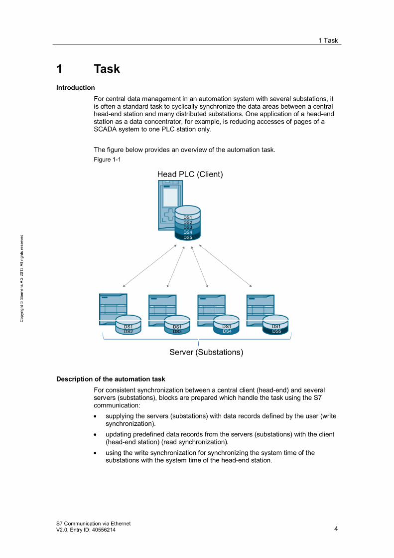
For central data management in an automation system with several substations, it is often a standard task to cyclically synchronize the data areas between a central head-end station and many distributed substations. One application of a head-end station as a data concentrator, for example, is reducing accesses of pages of a SCADA system to one PLC station only. The figure below provides an overview of the automation task. Figure 1-1
Head PLC (Client)
Server (Substations)
DS1
DS1 DS1 DS1
DS2
DS5DS4DS3
DS5DS3DS2DS1DS4
Description of the automation task For consistent synchronization between a central client (head-end) and several servers (substations), blocks are prepared which handle the task using the S7 communication: supplying the servers (substations) with data records defined by the user (write
synchronization). updating predefined data records from the servers (substations) with the client
(head-end station) (read synchronization). using the write synchronization for synchronizing the system time of the
substations with the system time of the head-end station.
1 Task
S7 Communication via Ethernet V2.0, Entry ID: 40556214 5
Cop
yrig
ht
Sie
men
s A
G 2
013
All
right
s re
serv
ed
Requirements for the automation task The following requirements are posed to the application. The synchronization must be performed in a consistent manner. The write synchronization occurs event-triggered from the user program. The read synchronization from the servers (substations) to the client (head-
end) occurs cyclically. The communication occurs via Ethernet using the S7 communication. The change of the quantity frameworks of the program (number of servers,
size and position of the send or receive data volumes) shall be as simple as possible.
It shall be possible to employ S7-CPUs of the S7-300/400 and S7-1500 as clients (head-end stations).
In the application, S7-1200 CPUs are used as servers (substations). Programming is preferably performed in SCL.
2 Solution 2.1 Overview
S7 Communication via Ethernet V2.0, Entry ID: 40556214 6
Cop
yrig
ht
Sie
men
s A
G 2
013
All
right
s re
serv
ed
2 Solution 2.1 Overview
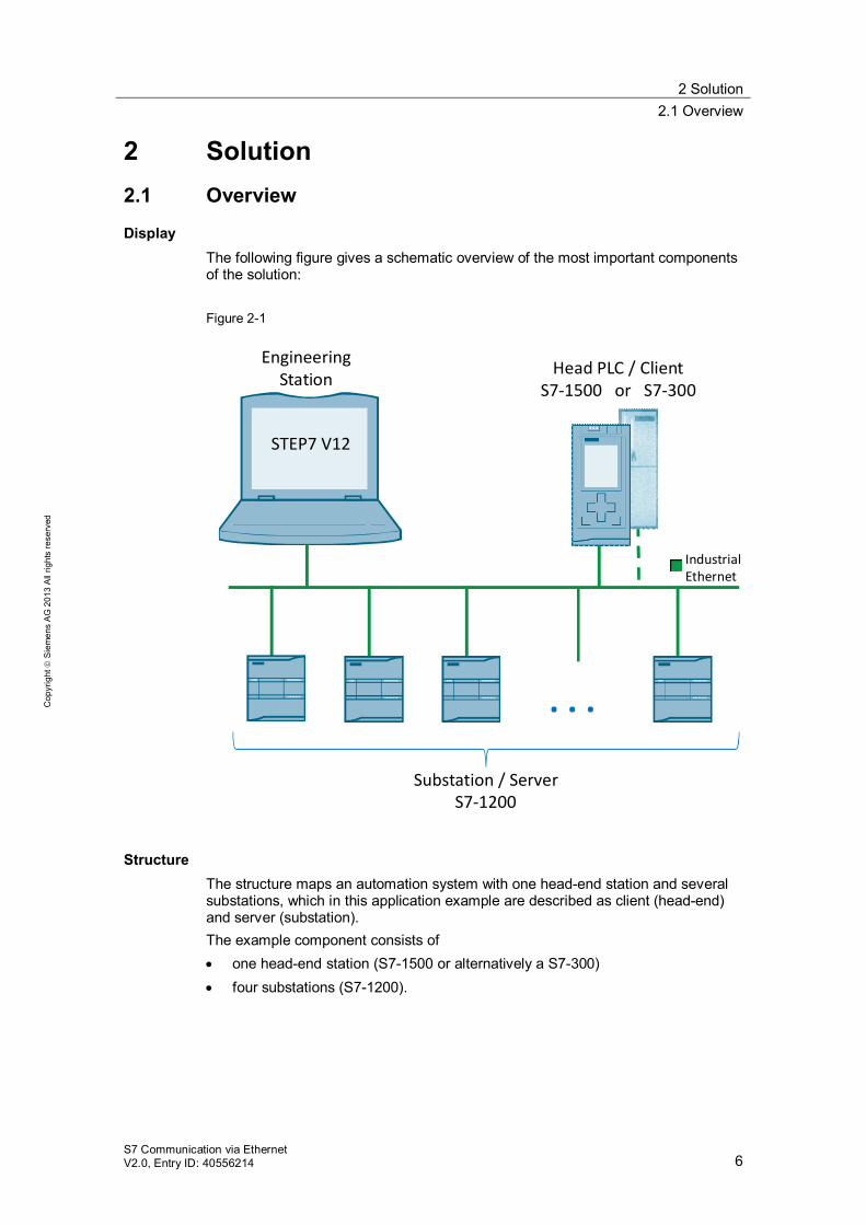
Display The following figure gives a schematic overview of the most important components of the solution: Figure 2-1
Engineering Station
STEP7 V12
Head PLC / ClientS7-1500 or S7-300
. . .
Substation / ServerS7-1200
Industrial Ethernet
Structure The structure maps an automation system with one head-end station and several substations, which in this application example are described as client (head-end) and server (substation). The example component consists of one head-end station (S7-1500 or alternatively a S7-300) four substations (S7-1200).
2 Solution 2.1 Overview
S7 Communication via Ethernet V2.0, Entry ID: 40556214 7
Cop
yrig
ht
Sie
men
s A
G 2
013
All
right
s re
serv
ed
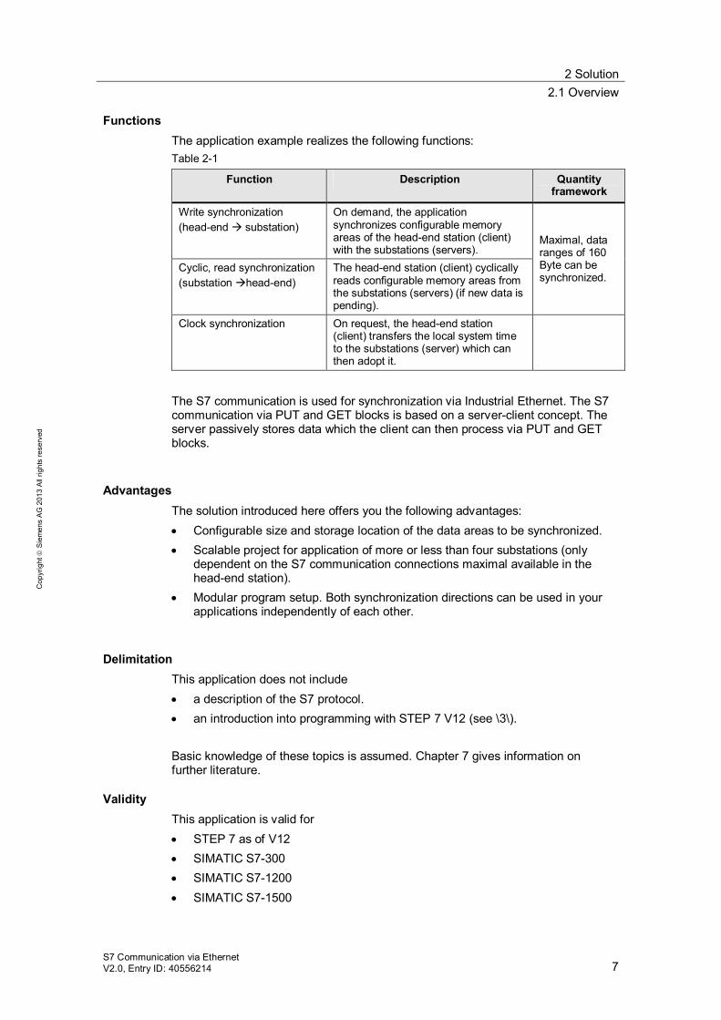
Functions The application example realizes the following functions: Table 2-1
Function Description Quantity framework
Write synchronization (head-end substation)
On demand, the application synchronizes configurable memory areas of the head-end station (client) with the substations (servers).
Maximal, data ranges of 160 Byte can be synchronized.
Cyclic, read synchronization (substation head-end)
The head-end station (client) cyclically reads configurable memory areas from the substations (servers) (if new data is pending).
Clock synchronization On request, the head-end station (client) transfers the local system time to the substations (server) which can then adopt it.
The S7 communication is used for synchronization via Industrial Ethernet. The S7 communication via PUT and GET blocks is based on a server-client concept. The server passively stores data which the client can then process via PUT and GET blocks.
Advantages The solution introduced here offers you the following advantages: Configurable size and storage location of the data areas to be synchronized. Scalable project for application of more or less than four substations (only
dependent on the S7 communication connections maximal available in the head-end station).
Modular program setup. Both synchronization directions can be used in your applications independently of each other.
Delimitation This application does not include a description of the S7 protocol. an introduction into programming with STEP 7 V12 (see \3\).
Basic knowledge of these topics is assumed. Chapter 7 gives information on further literature.
Validity This application is valid for STEP 7 as of V12 SIMATIC S7-300 SIMATIC S7-1200 SIMATIC S7-1500
2 Solution 2.2 Required hardware and software components
S7 Communication via Ethernet V2.0, Entry ID: 40556214 8
Cop
yrig
ht
Sie
men
s A
G 2
013
All
right
s re
serv
ed
2.2 Required hardware and software components
This application was generated with the following components:
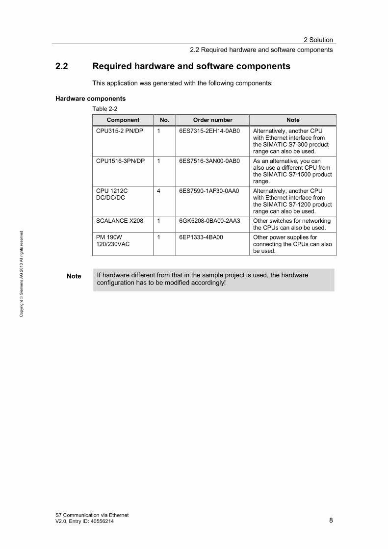
Hardware components Table 2-2
Component No. Order number Note
CPU315-2 PN/DP 1 6ES7315-2EH14-0AB0 Alternatively, another CPU with Ethernet interface from the SIMATIC S7-300 product range can also be used.
CPU1516-3PN/DP 1 6ES7516-3AN00-0AB0 As an alternative, you can also use a different CPU from the SIMATIC S7-1500 product range.
CPU 1212C DC/DC/DC
4 6ES7590-1AF30-0AA0 Alternatively, another CPU with Ethernet interface from the SIMATIC S7-1200 product range can also be used.
SCALANCE X208 1 6GK5208-0BA00-2AA3 Other switches for networking the CPUs can also be used.
PM 190W 120/230VAC
1 6EP1333-4BA00 Other power supplies for connecting the CPUs can also be used.
Note If hardware different from that in the sample project is used, the hardware configuration has to be modified accordingly!
2 Solution 2.2 Required hardware and software components
S7 Communication via Ethernet V2.0, Entry ID: 40556214 9
Cop
yrig
ht
Sie
men
s A
G 2
013
All
right
s re
serv
ed
Software components Table 2-3
Component No. Order number Note
STEP 7 V12 (TIA Portal V12)
1 6ES78221AE02-0YA5
Sample files and projects The following list includes all files and projects that are used in this example. Table 2-4
Component Note
40556214_S7-Comm_Sync_CODE_v1.zip This zip file contains the STEP 7 project. 40556214_S7-Komm_Sync_DOKU_v1_e.pdf
This document.
2 Solution 2.3 Performance data
S7 Communication via Ethernet V2.0, Entry ID: 40556214 10
Cop
yrig
ht
Sie
men
s A
G 2
013
All
right
s re
serv
ed
2.3 Performance data
2.3.1 Synchronization speed
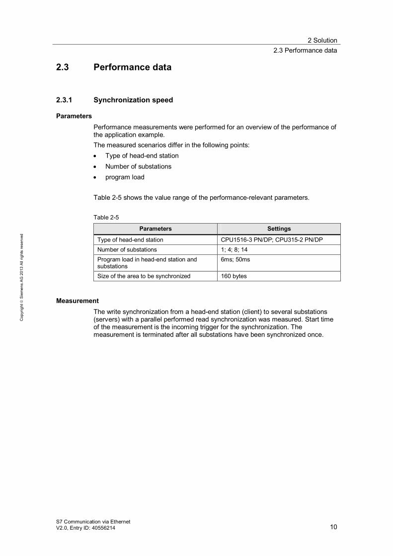
Parameters Performance measurements were performed for an overview of the performance of the application example. The measured scenarios differ in the following points: Type of head-end station Number of substations program load
Table 2-5 shows the value range of the performance-relevant parameters. Table 2-5
Parameters Settings
Type of head-end station CPU1516-3 PN/DP; CPU315-2 PN/DP Number of substations 1; 4; 8; 14 Program load in head-end station and substations
6ms; 50ms
Size of the area to be synchronized 160 bytes
Measurement The write synchronization from a head-end station (client) to several substations (servers) with a parallel performed read synchronization was measured. Start time of the measurement is the incoming trigger for the synchronization. The measurement is terminated after all substations have been synchronized once.
2 Solution 2.3 Performance data
S7 Communication via Ethernet V2.0, Entry ID: 40556214 11
Cop
yrig
ht
Sie
men
s A
G 2
013
All
right
s re
serv
ed
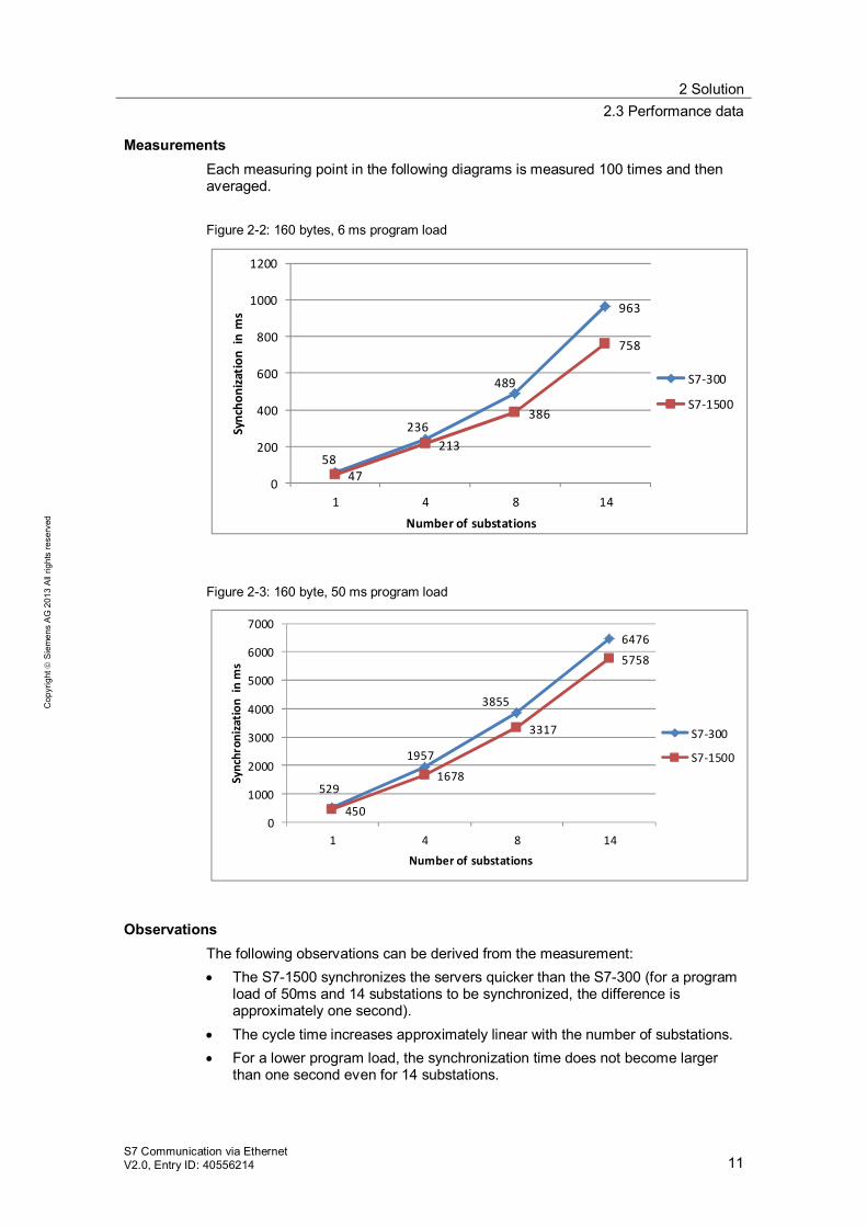
Measurements Each measuring point in the following diagrams is measured 100 times and then averaged. Figure 2-2: 160 bytes, 6 ms program load
58
236
489
963
47
213
386
758
0
200
400
600
800
1000
1200
1 4 8 14
Sync
honi
zatio
n in
ms
Number of substations
S7-300
S7-1500
Figure 2-3: 160 byte, 50 ms program load
529
1957
3855
6476
450
1678
3317
5758
0
1000
2000
3000
4000
5000
6000
7000
1 4 8 14
Sync
hron
izatio
n in
ms
Number of substations
S7-300
S7-1500
Observations The following observations can be derived from the measurement: The S7-1500 synchronizes the servers quicker than the S7-300 (for a program
load of 50ms and 14 substations to be synchronized, the difference is approximately one second).
The cycle time increases approximately linear with the number of substations. For a lower program load, the synchronization time does not become larger
than one second even for 14 substations.
2 Solution 2.4 Alternative
S7 Communication via Ethernet V2.0, Entry ID: 40556214 12
Cop
yrig
ht
Sie
men
s A
G 2
013
All
right
s re
serv
ed
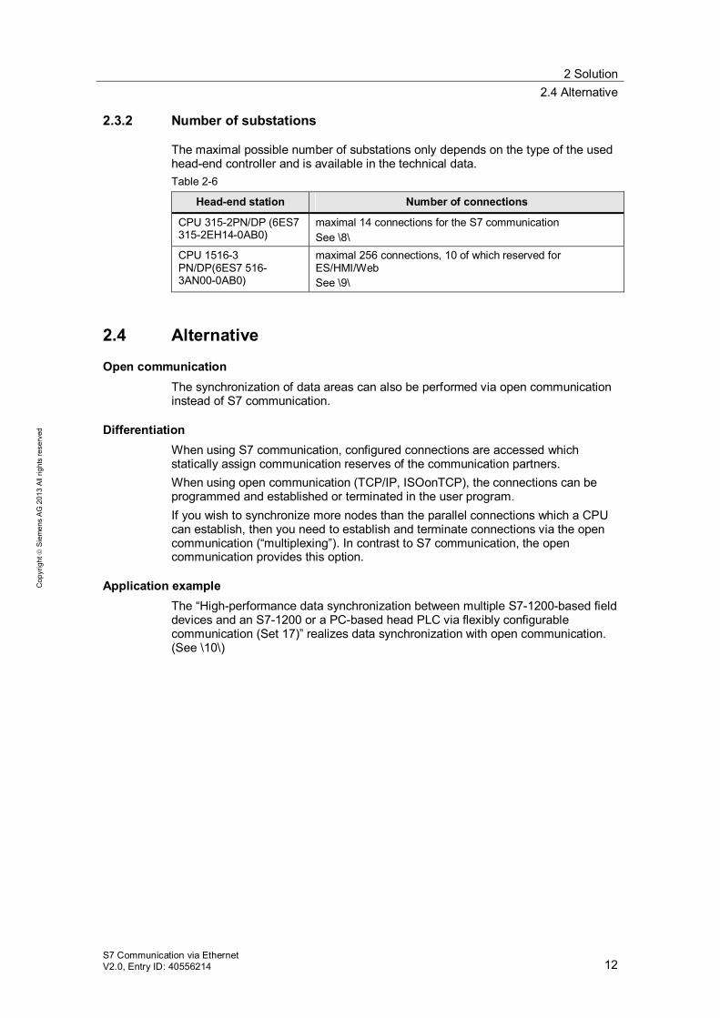
2.3.2 Number of substations
The maximal possible number of substations only depends on the type of the used head-end controller and is available in the technical data. Table 2-6
Head-end station Number of connections
CPU 315-2PN/DP (6ES7 315-2EH14-0AB0)
maximal 14 connections for the S7 communication See \8\
CPU 1516-3 PN/DP(6ES7 516-3AN00-0AB0)
maximal 256 connections, 10 of which reserved for ES/HMI/Web See \9\
2.4 Alternative
Open communication The synchronization of data areas can also be performed via open communication instead of S7 communication.
Differentiation When using S7 communication, configured connections are accessed which statically assign communication reserves of the communication partners. When using open communication (TCP/IP, ISOonTCP), the connections can be programmed and established or terminated in the user program. If you wish to synchronize more nodes than the parallel connections which a CPU can establish, then you need to establish and terminate connections via the open communication (“multiplexing”). In contrast to S7 communication, the open communication provides this option.
Application example The “High-performance data synchronization between multiple S7-1200-based field devices and an S7-1200 or a PC-based head PLC via flexibly configurable communication (Set 17)” realizes data synchronization with open communication. (See \10\)
3 Functional Mechanisms of the Application 3.1 Overview
S7 Communication via Ethernet V2.0, Entry ID: 40556214 13
Cop
yrig
ht
Sie
men
s A
G 2
013
All
right
s re
serv
ed
3 Functional Mechanisms of the Application This chapter describes the functions of the application. Chapter 3.1 explains what the terms read and write synchronization refer to. Chapter 3.2 and 3.3 explain the structure of the user programs of client and server.
3.1 Overview
On request, the application synchronizes memory areas of the client (either an S7-300 or an S7-1500) with four servers. Data is written cyclically from four servers into memory areas of the client. The following sections provide an overview over the process of write and read synchronization.
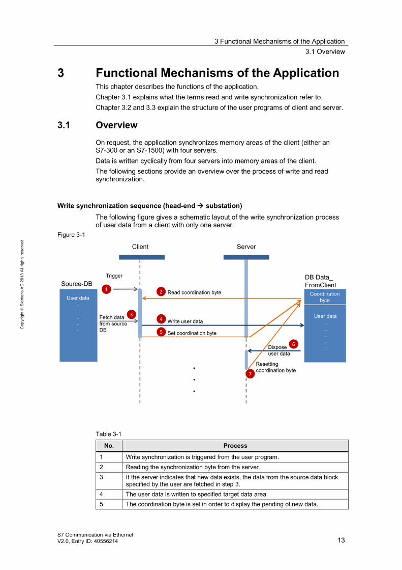
Write synchronization sequence (head-end substation) The following figure gives a schematic layout of the write synchronization process of user data from a client with only one server.
Figure 3-1
Resetting coordination byte
Client Server
Read coordination byte2
43
Write user dataFetch data from source DB 5
1
Trigger
Disposeuser data
6
.
.
.
7
User data..........
DB Data_FromClientSource-DB
Set coordination byte
Coordination byteUser data
..
..
..
..
..
Table 3-1
No. Process
1 Write synchronization is triggered from the user program. 2 Reading the synchronization byte from the server. 3 If the server indicates that new data exists, the data from the source data block
specified by the user are fetched in step 3. 4 The user data is written to specified target data area. 5 The coordination byte is set in order to display the pending of new data.
3 Functional Mechanisms of the Application 3.1 Overview
S7 Communication via Ethernet V2.0, Entry ID: 40556214 14
Cop
yrig
ht
Sie
men
s A
G 2
013
All
right
s re
serv
ed
No. Process
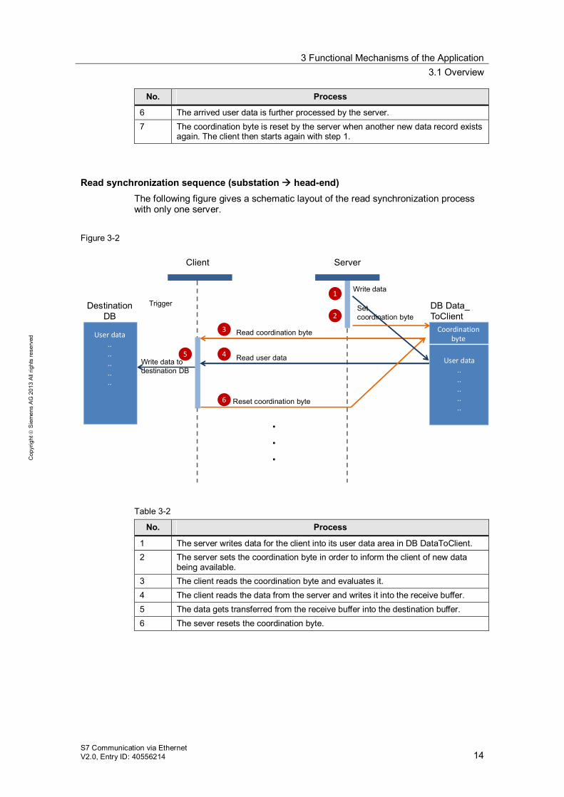
6 The arrived user data is further processed by the server. 7 The coordination byte is reset by the server when another new data record exists
again. The client then starts again with step 1.
Read synchronization sequence (substation head-end) The following figure gives a schematic layout of the read synchronization process with only one server.
Figure 3-2
Write data todestination DB
Client Server
Read coordination byte3
45 Read user data
6
Trigger
.
.
.
User data..........
DB Data_ToClient
Destination DB
Reset coordination byte
Coordination byteUser data
..
..
..
..
..
1 Write data
Setcoordination byte2
Table 3-2
No. Process
1 The server writes data for the client into its user data area in DB DataToClient. 2 The server sets the coordination byte in order to inform the client of new data
being available. 3 The client reads the coordination byte and evaluates it. 4 The client reads the data from the server and writes it into the receive buffer. 5 The data gets transferred from the receive buffer into the destination buffer. 6 The sever resets the coordination byte.
3 Functional Mechanisms of the Application 3.1 Overview
S7 Communication via Ethernet V2.0, Entry ID: 40556214 15
Cop
yrig
ht
Sie
men
s A
G 2
013
All
right
s re
serv
ed
CPUs in the project The following S7-CPUs have been configured in the STEP 7 V12 project: CPU 1516-3 PN/DP (client) CPU 315-2 PN/DP (client) four CPU 1212 DC/DC/DC (server)
Both clients have the same functionality and can be used alternatively as head-end station.
Functions of the client As the active part, the central client (either an S7-1500 or an S7-300 station) realizes the synchronization of data areas with the servers. The synchronization is divided into write (see Figure 3-1) and read (see Figure 3-2) synchronization. For both synchronization types, the user can specify different data areas individually for each server. The write synchronization is also used to perform a clock synchronization with the servers.
Functions of the server As the passive part, the server(s) (one or several S7-1200 stations) reacts to the synchronization jobs of the client. In order for the server program to react to the actions of the client, as well as to ensure data consistency, it must be known which data areas are to be synchronized.
3 Functional Mechanisms of the Application 3.2 Description of the program of the head-end station
S7 Communication via Ethernet V2.0, Entry ID: 40556214 16
Cop
yrig
ht
Sie
men
s A
G 2
013
All
right
s re
serv
ed
3.2 Description of the program of the head-end station
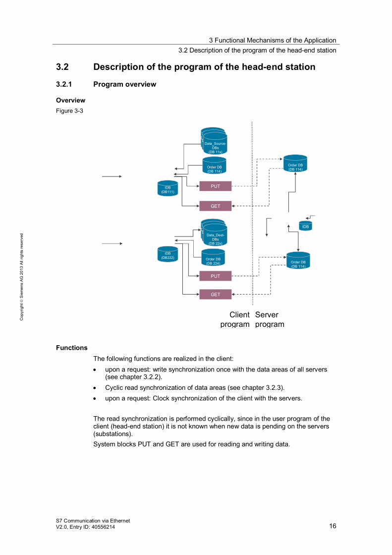
3.2.1 Program overview
Overview Figure 3-3
Sync_Client2Serv(FB111)
PUT
GET
IDB(DB111)
Sync_Client2Serv(FB222)
Order DB(DB 114)
Client program
Main (OB1)
Call Sync_Client2Serv
Call Sync_Serv2Client
PUT
GET
IDB(DB222) Order DB
(DB 224)
Data_Source-DBs
(DB 11x)
Data_Source-DBs
(DB 11x)
Data_Source-DBs
(DB 11x)
Data_Source-DBs
(DB 11x)
Data_Source-DBs
(DB 11x)
Data_Dest-DBs
(DB 22x)
Order DB(DB 114)
Order DB(DB 114)
Sync_Server(FB1)
IDB
Server program
Main (OB1)
DnT_DTL(FC1200)
Call Sync_Server
Functions The following functions are realized in the client: upon a request: write synchronization once with the data areas of all servers
(see chapter 3.2.2). Cyclic read synchronization of data areas (see chapter 3.2.3). upon a request: Clock synchronization of the client with the servers.
The read synchronization is performed cyclically, since in the user program of the client (head-end station) it is not known when new data is pending on the servers (substations). System blocks PUT and GET are used for reading and writing data.
3 Functional Mechanisms of the Application 3.2 Description of the program of the head-end station
S7 Communication via Ethernet V2.0, Entry ID: 40556214 17
Cop
yrig
ht
Sie
men
s A
G 2
013
All
right
s re
serv
ed
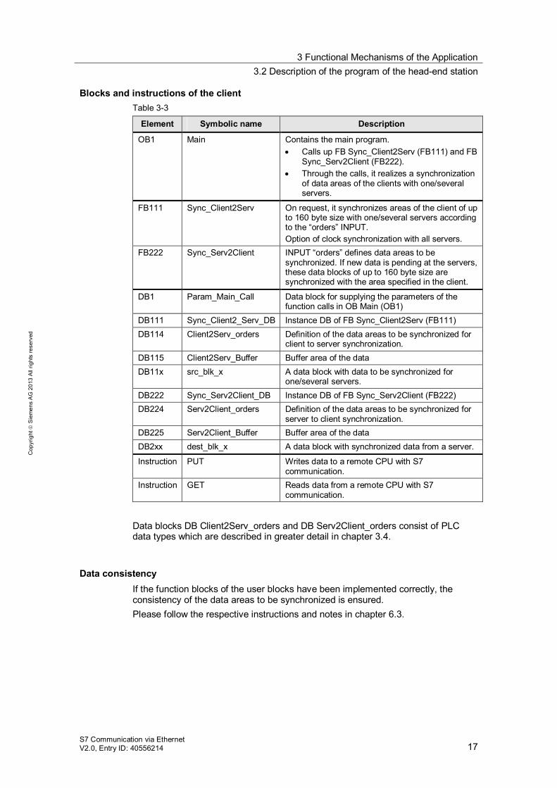
Blocks and instructions of the client Table 3-3
Element Symbolic name Description
OB1 Main Contains the main program. Calls up FB Sync_Client2Serv (FB111) and FB
Sync_Serv2Client (FB222). Through the calls, it realizes a synchronization
of data areas of the clients with one/several servers.
FB111 Sync_Client2Serv On request, it synchronizes areas of the client of up to 160 byte size with one/several servers according to the “orders” INPUT. Option of clock synchronization with all servers.
FB222 Sync_Serv2Client INPUT “orders” defines data areas to be synchronized. If new data is pending at the servers, these data blocks of up to 160 byte size are synchronized with the area specified in the client.
DB1 Param_Main_Call Data block for supplying the parameters of the function calls in OB Main (OB1)
DB111 Sync_Client2_Serv_DB Instance DB of FB Sync_Client2Serv (FB111) DB114 Client2Serv_orders Definition of the data areas to be synchronized for
client to server synchronization. DB115 Client2Serv_Buffer Buffer area of the data DB11x src_blk_x A data block with data to be synchronized for
one/several servers. DB222 Sync_Serv2Client_DB Instance DB of FB Sync_Serv2Client (FB222) DB224 Serv2Client_orders Definition of the data areas to be synchronized for
server to client synchronization. DB225 Serv2Client_Buffer Buffer area of the data DB2xx dest_blk_x A data block with synchronized data from a server.
Instruction PUT Writes data to a remote CPU with S7 communication.
Instruction GET Reads data from a remote CPU with S7 communication.
Data blocks DB Client2Serv_orders and DB Serv2Client_orders consist of PLC data types which are described in greater detail in chapter 3.4.
Data consistency If the function blocks of the user blocks have been implemented correctly, the consistency of the data areas to be synchronized is ensured. Please follow the respective instructions and notes in chapter 6.3.
3 Functional Mechanisms of the Application 3.2 Description of the program of the head-end station
S7 Communication via Ethernet V2.0, Entry ID: 40556214 18
Cop
yrig
ht
Sie
men
s A
G 2
013
All
right
s re
serv
ed
3.2.2 FB Sync_Client2Serv (FB111): Write synchronization
Overview FB Sync_Client2Serv (FB111) realizes the write synchronization of the specified data areas on the S7 servers (substations). On request, the FB performs reading and evaluation of the coordination byte of the destination data area. writing of new data to the server.
Here, the example program synchronizes the maximal possible 160 bytes of user data. In order to synchronize data volumes smaller than 160 bytes, please follow the instructions and notes in chapter 6.1.
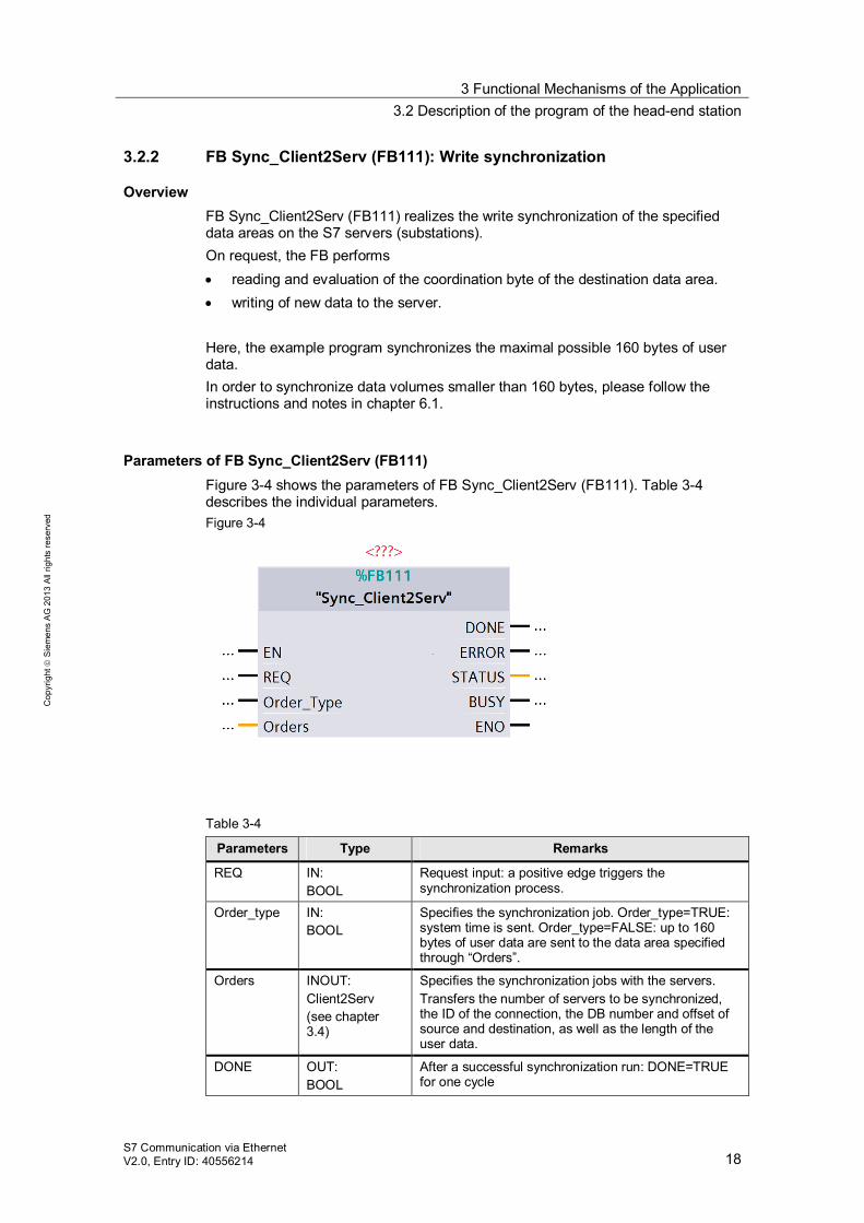
Parameters of FB Sync_Client2Serv (FB111) Figure 3-4 shows the parameters of FB Sync_Client2Serv (FB111). Table 3-4 describes the individual parameters. Figure 3-4
Table 3-4
Parameters Type Remarks
REQ IN: BOOL
Request input: a positive edge triggers the synchronization process.
Order_type IN: BOOL
Specifies the synchronization job. Order_type=TRUE: system time is sent. Order_type=FALSE: up to 160 bytes of user data are sent to the data area specified through “Orders”.
Orders INOUT: Client2Serv (see chapter 3.4)
Specifies the synchronization jobs with the servers. Transfers the number of servers to be synchronized, the ID of the connection, the DB number and offset of source and destination, as well as the length of the user data.
DONE OUT: BOOL
After a successful synchronization run: DONE=TRUE for one cycle
3 Functional Mechanisms of the Application 3.2 Description of the program of the head-end station
S7 Communication via Ethernet V2.0, Entry ID: 40556214 19
Cop
yrig
ht
Sie
men
s A
G 2
013
All
right
s re
serv
ed
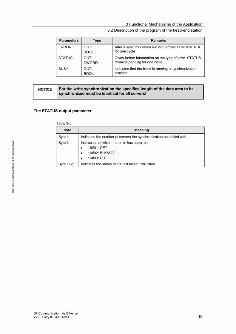
Parameters Type Remarks
ERROR OUT: BOOL
After a synchronization run with errors: ERROR=TRUE for one cycle
STATUS OUT: DWORD
Gives further information on the type of error. STATUS remains pending for one cycle.
BUSY OUT: BOOL
Indicates that the block is running a synchronization process
NOTICE For the write synchronization the specified length of the data area to be synchronized must be identical for all servers!
The STATUS output parameter Table 3-5
Byte Meaning
Byte 4 Indicates the number of servers the synchronization has failed with. Byte 3 Instruction at which the error has occurred.
16#01: GET 16#02: BLKMOV 16#03: PUT
Byte 1+2 Indicates the status of the last failed instruction.
3 Functional Mechanisms of the Application 3.2 Description of the program of the head-end station
S7 Communication via Ethernet V2.0, Entry ID: 40556214 20
Cop
yrig
ht
Sie
men
s A
G 2
013
All
right
s re
serv
ed
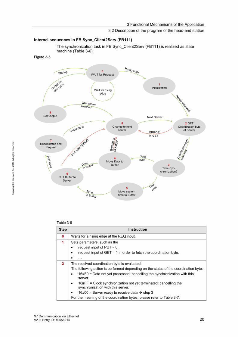
Internal sequences in FB Sync_Client2Serv (FB111) The synchronization task in FB Sync_Client2Serv (FB111) is realized as state machine (Table 3-6).
Figure 3-5
0WAIT for Request
8Change to next
server
6PUT Buffer to
Server
5Move systemtime to Buffer
4Move Data to
Buffer 3Time Syn-
chronization?
2 GET Coordination byte
of Server
1Initialization
9Set Output
ERROR in GET
Next Server
Wait for risingedge
7Reset status and
Request
Table 3-6
Step Instruction
0 Waits for a rising edge at the REQ input. 1 Sets parameters, such as the
request input of PUT = 0. request input of GET = 1 in order to fetch the coordination byte. …
2 The received coordination byte is evaluated. The following action is performed depending on the status of the coordination byte: 16#F0 = Data not yet processed: cancelling the synchronization with this
server. 16#FF = Clock synchronization not yet terminated: cancelling the
synchronization with this server. 16#00 = Server ready to receive data step 3
For the meaning of the coordination bytes, please refer to Table 3-7.
3 Functional Mechanisms of the Application 3.2 Description of the program of the head-end station
S7 Communication via Ethernet V2.0, Entry ID: 40556214 21
Cop
yrig
ht
Sie
men
s A
G 2
013
All
right
s re
serv
ed
Step Instruction
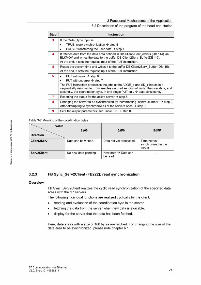
3 If the Order_type input is TRUE: clock synchronization step 5 FALSE: transferring the user data step 4
4 It fetches data from the data area defined in DB Client2Serv_orders (DB 114) via BLKMOV and writes the data to the buffer DB Client2Serv_Buffer(DB115). At the end, it sets the request input of the PUT instruction.
5 Reads the system time and writes it to the buffer DB Client2Serv_Buffer (DB115). At the end, it sets the request input of the PUT instruction.
6 PUT with error step 8 PUT without error step 7
The PUT instruction processes the jobs at the ADDR_x and SD_x inputs in a sequentially rising order. This enables secured sending of firstly, the user data, and secondly, the coordination byte, in one single PUT call. data consistency
7 Resetting the status for the active server step 8 8 Changing the server to be synchronized by incrementing “control.number” step 2
After attempting to synchronize all of the servers once step 9 9 Sets the output parameters, see Table 3-5. step 0
Table 3-7 Meaning of the coordination bytes
Value
Direction
16#00
16#F0
16#FF
Client2Serv Data can be written. Data not yet processed. Time not yet synchronized in the server
Serv2Client No new data pending. New data Data can be read.
---
3.2.3 FB Sync_Serv2Client (FB222): read synchronization
Overview FB Sync_Serv2Client realizes the cyclic read synchronization of the specified data areas with the S7 servers. The following individual functions are realized cyclically by the client: reading and evaluation of the coordination byte in the server. fetching the data from the server when new data is available. display for the server that the data has been fetched.
Here, data areas with a size of 160 bytes are fetched. For changing the size of the data area to be synchronized, please note chapter 6.1.
3 Functional Mechanisms of the Application 3.2 Description of the program of the head-end station
S7 Communication via Ethernet V2.0, Entry ID: 40556214 22
Cop
yrig
ht
Sie
men
s A
G 2
013
All
right
s re
serv
ed
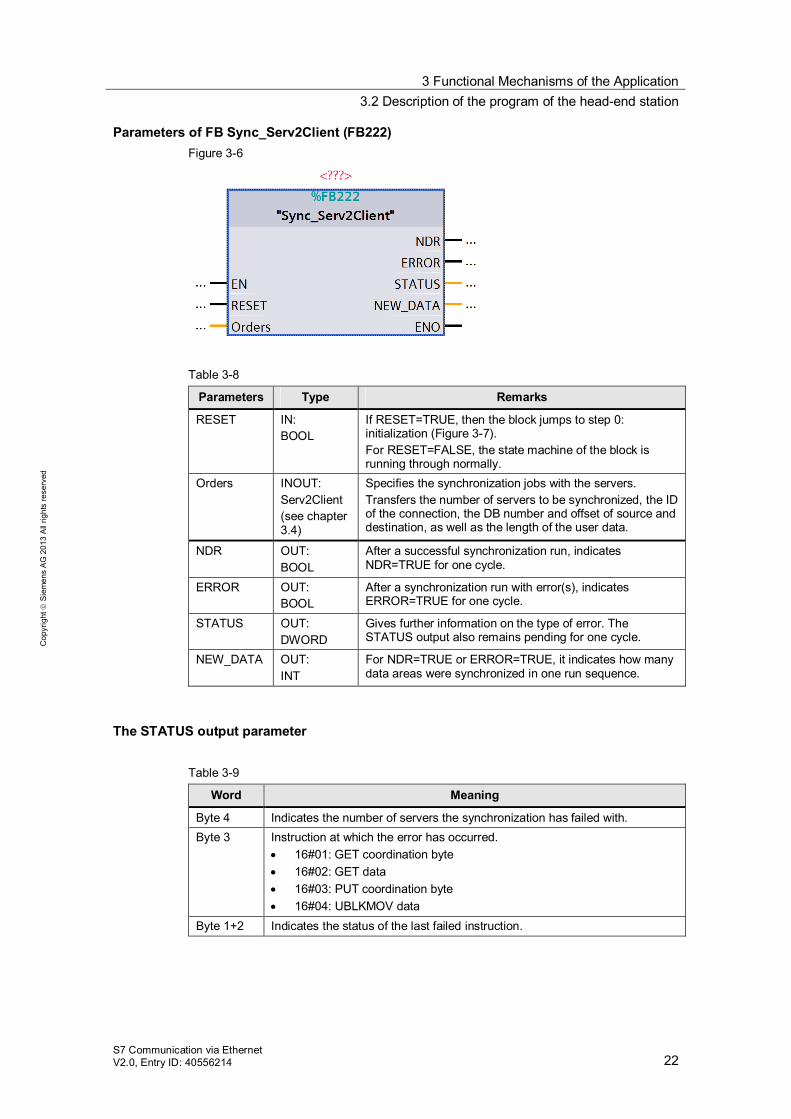
Parameters of FB Sync_Serv2Client (FB222) Figure 3-6
Table 3-8
Parameters Type Remarks
RESET IN: BOOL
If RESET=TRUE, then the block jumps to step 0: initialization (Figure 3-7). For RESET=FALSE, the state machine of the block is running through normally.
Orders INOUT: Serv2Client (see chapter 3.4)
Specifies the synchronization jobs with the servers. Transfers the number of servers to be synchronized, the ID of the connection, the DB number and offset of source and destination, as well as the length of the user data.
NDR OUT: BOOL
After a successful synchronization run, indicates NDR=TRUE for one cycle.
ERROR OUT: BOOL
After a synchronization run with error(s), indicates ERROR=TRUE for one cycle.
STATUS OUT: DWORD
Gives further information on the type of error. The STATUS output also remains pending for one cycle.
NEW_DATA OUT: INT
For NDR=TRUE or ERROR=TRUE, it indicates how many data areas were synchronized in one run sequence.
The STATUS output parameter Table 3-9
Word Meaning
Byte 4 Indicates the number of servers the synchronization has failed with. Byte 3 Instruction at which the error has occurred.
16#01: GET coordination byte 16#02: GET data 16#03: PUT coordination byte 16#04: UBLKMOV data
Byte 1+2 Indicates the status of the last failed instruction.
3 Functional Mechanisms of the Application 3.2 Description of the program of the head-end station
S7 Communication via Ethernet V2.0, Entry ID: 40556214 23
Cop
yrig
ht
Sie
men
s A
G 2
013
All
right
s re
serv
ed
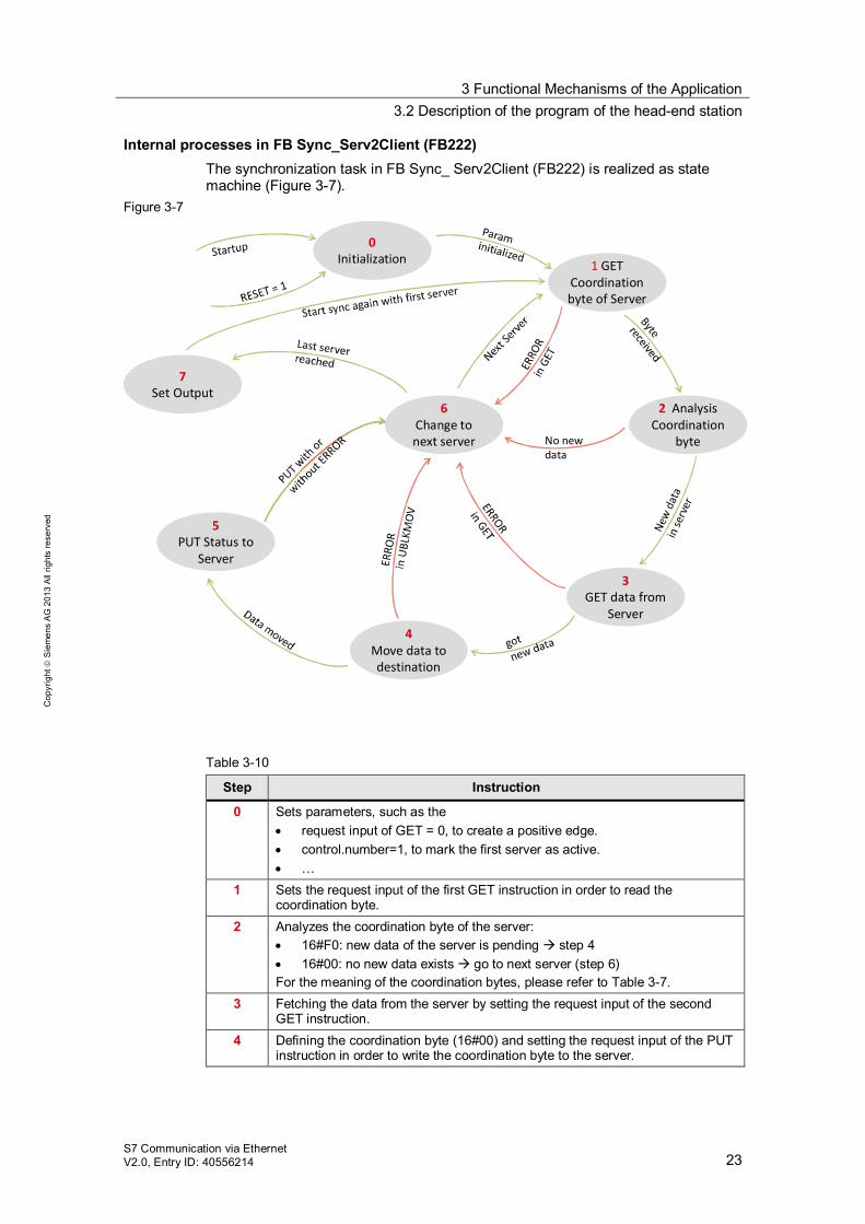
Internal processes in FB Sync_Serv2Client (FB222) The synchronization task in FB Sync_ Serv2Client (FB222) is realized as state machine (Figure 3-7).
Figure 3-7
0Initialization
6Change to next server
5PUT Status to
Server
2 Analysis Coordination
byte
1 GET Coordinationbyte of Server
7Set Output
No new data
3GET data from
Server4
Move data to destination
Table 3-10
Step Instruction
0 Sets parameters, such as the request input of GET = 0, to create a positive edge. control.number=1, to mark the first server as active. …
1 Sets the request input of the first GET instruction in order to read the coordination byte.
2 Analyzes the coordination byte of the server: 16#F0: new data of the server is pending step 4 16#00: no new data exists go to next server (step 6)
For the meaning of the coordination bytes, please refer to Table 3-7. 3 Fetching the data from the server by setting the request input of the second
GET instruction. 4 Defining the coordination byte (16#00) and setting the request input of the PUT
instruction in order to write the coordination byte to the server.
3 Functional Mechanisms of the Application 3.3 Description of the program of a substation
S7 Communication via Ethernet V2.0, Entry ID: 40556214 24
Cop
yrig
ht
Sie
men
s A
G 2
013
All
right
s re
serv
ed
Step Instruction
5 Fetching the data from the buffer and storing it in the destination DB with the UBLKMOV instruction.
6 Changing the server to be synchronized by incrementing “control.number” step 1 After synchronization has been attempted for all of the servers once, the first server is marked as active jump to step 7
7 Setting the output parameters step 1 for a new synchronization run.
3.3 Description of the program of a substation
3.3.1 Program overview
Functions The server reacts only passively to the synchronization through the client. The PUT/GET blocks are only called up in the client (head-end station), and only the client can determine the end of a write/read process. The passive server does not contain any active communication blocks and needs to control the coordination of the accesses through the user program. The following functions have been realized in the user program of the server (substation): coordination of the disposal of data by the client (write synchronization with the
substation). coordination of the supply of data to the client (read synchronization from the
substation). Setting the system time at a time synchronization job.
A graphic program overview is described in Figure 3-3.
Blocks and instructions in the substation Table 3-11
Element Symbolic name Description
OB1 Main Contains the main program. Calls the FB Sync_Serv2Client (FB2) The call implements a receive logic for the
synchronization with the client.
FB2 Sync_Server Reacts to the synchronization from the client. The information which DBs are synchronized must be transferred to the FB. Any deviation from the example application must be adjusted in the user program (see chapter 6).
FC1200 DnT_DTL Transforms the Date_and_Time data type into data type DTL.
DB2 Sync_Server_DB Instance DB of FB Sync_Server (FB2) DB6 Data_FromClient Storage location of the data from the client. DB7 Data_ToClient Storage location of the data for the client.
3 Functional Mechanisms of the Application 3.3 Description of the program of a substation
S7 Communication via Ethernet V2.0, Entry ID: 40556214 25
Cop
yrig
ht
Sie
men
s A
G 2
013
All
right
s re
serv
ed
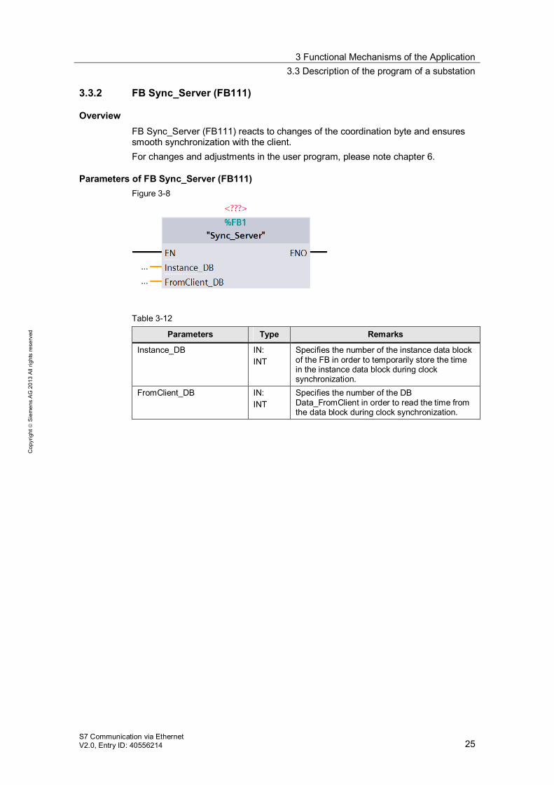
3.3.2 FB Sync_Server (FB111)
Overview FB Sync_Server (FB111) reacts to changes of the coordination byte and ensures smooth synchronization with the client. For changes and adjustments in the user program, please note chapter 6.
Parameters of FB Sync_Server (FB111) Figure 3-8
Table 3-12
Parameters Type Remarks
Instance_DB IN: INT
Specifies the number of the instance data block of the FB in order to temporarily store the time in the instance data block during clock synchronization.
FromClient_DB IN: INT
Specifies the number of the DB Data_FromClient in order to read the time from the data block during clock synchronization.
3 Functional Mechanisms of the Application 3.3 Description of the program of a substation
S7 Communication via Ethernet V2.0, Entry ID: 40556214 26
Cop
yrig
ht
Sie
men
s A
G 2
013
All
right
s re
serv
ed
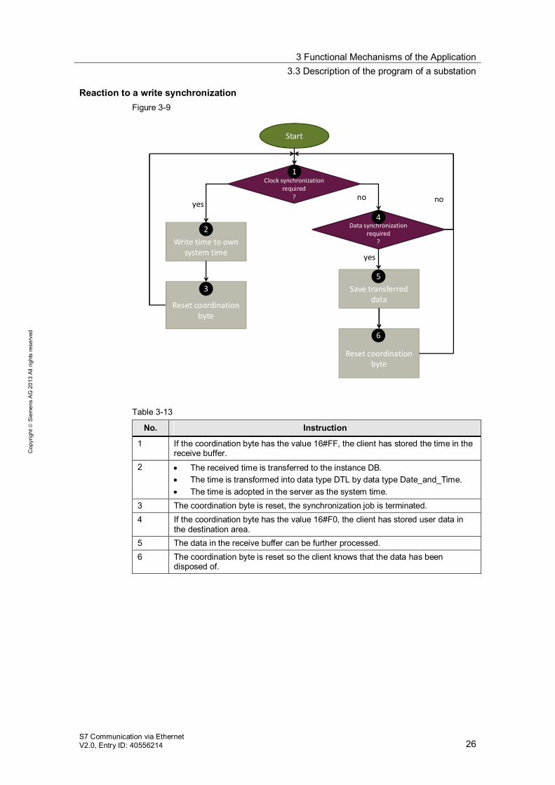
Reaction to a write synchronization Figure 3-9
Start
Clock synchronizationrequired
?
Write time to own system time
yes
Data synchronizationrequired
?
Reset coordination byte
no no
yes
Save transferred data
Reset coordination byte
1
2
3
4
5
6
Table 3-13
No. Instruction
1 If the coordination byte has the value 16#FF, the client has stored the time in the receive buffer.
2 The received time is transferred to the instance DB. The time is transformed into data type DTL by data type Date_and_Time. The time is adopted in the server as the system time.
3 The coordination byte is reset, the synchronization job is terminated. 4 If the coordination byte has the value 16#F0, the client has stored user data in
the destination area. 5 The data in the receive buffer can be further processed. 6 The coordination byte is reset so the client knows that the data has been
disposed of.
3 Functional Mechanisms of the Application 3.3 Description of the program of a substation
S7 Communication via Ethernet V2.0, Entry ID: 40556214 27
Cop
yrig
ht
Sie
men
s A
G 2
013
All
right
s re
serv
ed
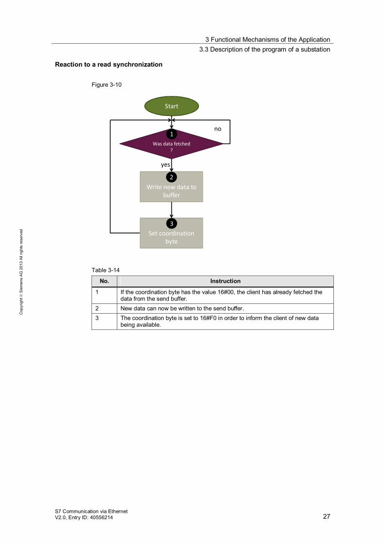
Reaction to a read synchronization Figure 3-10
Start
Was data fetched?
Write new data to buffer
yes
Set coordination byte
no1
2
3
Table 3-14
No. Instruction
1 If the coordination byte has the value 16#00, the client has already fetched the data from the send buffer.
2 New data can now be written to the send buffer. 3 The coordination byte is set to 16#F0 in order to inform the client of new data
being available.
3 Functional Mechanisms of the Application 3.4 The PLC data types
S7 Communication via Ethernet V2.0, Entry ID: 40556214 28
Cop
yrig
ht
Sie
men
s A
G 2
013
All
right
s re
serv
ed
3.3.3 Data consistency in the server
Definition The term data consistency refers to the data, which is synchronized between client and server, being transferred in a correct state. Data inconsistency can occur if two processes asynchronously access the same storage area. One possible scenario is that the clearly faster read access “overtakes” the write access, resulting in the read data consisting of old and new values, which makes them inconsistent.
Requirements Communication with PUT and GET functions is considered uncoordinated communication, since the server cannot directly react to the jobs of the client. Communication with BSEND and BRCV enables inquiring whether data can still be sent or received. In contrast, the PUT and GET functions require a coordination of the accesses in the user program.
Actions Access in the user program is controlled via the “coordination byte”. Its exact meaning, as well as measures for maintaining the data consistency of the program, is available in chapter 6.3 and 6.4.
3.4 The PLC data types
Overview The following PLC data types are used in the user program of the client (head-end station): “order” “Client2Serv” “Serv2Client” “Any_struct”
This chapter describes the structure and usage of the data types.
3 Functional Mechanisms of the Application 3.4 The PLC data types
S7 Communication via Ethernet V2.0, Entry ID: 40556214 29
Cop
yrig
ht
Sie
men
s A
G 2
013
All
right
s re
serv
ed
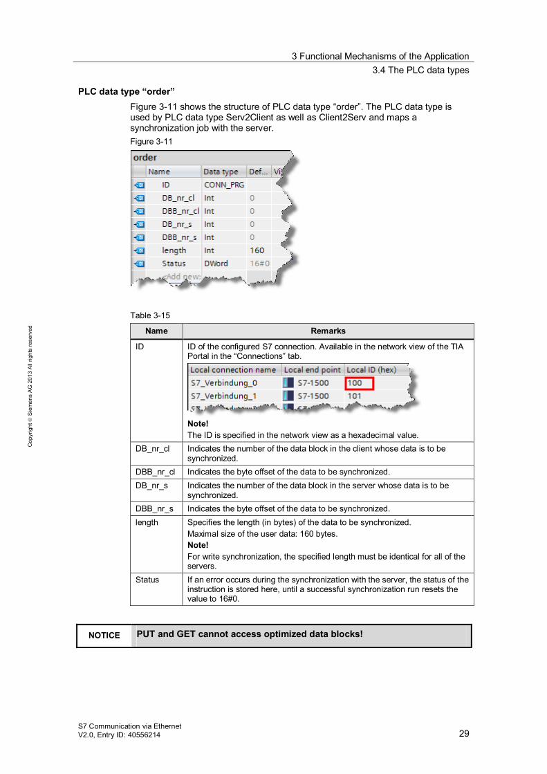
PLC data type “order” Figure 3-11 shows the structure of PLC data type “order”. The PLC data type is used by PLC data type Serv2Client as well as Client2Serv and maps a synchronization job with the server. Figure 3-11
Table 3-15
Name Remarks
ID ID of the configured S7 connection. Available in the network view of the TIA Portal in the “Connections” tab.
Note! The ID is specified in the network view as a hexadecimal value.
DB_nr_cl Indicates the number of the data block in the client whose data is to be synchronized.
DBB_nr_cl Indicates the byte offset of the data to be synchronized. DB_nr_s Indicates the number of the data block in the server whose data is to be
synchronized. DBB_nr_s Indicates the byte offset of the data to be synchronized. length Specifies the length (in bytes) of the data to be synchronized.
Maximal size of the user data: 160 bytes. Note! For write synchronization, the specified length must be identical for all of the servers.
Status If an error occurs during the synchronization with the server, the status of the instruction is stored here, until a successful synchronization run resets the value to 16#0.
NOTICE PUT and GET cannot access optimized data blocks!
3 Functional Mechanisms of the Application 3.4 The PLC data types
S7 Communication via Ethernet V2.0, Entry ID: 40556214 30
Cop
yrig
ht
Sie
men
s A
G 2
013
All
right
s re
serv
ed
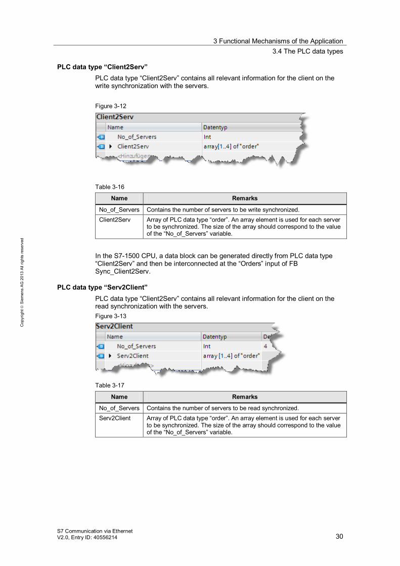
PLC data type “Client2Serv” PLC data type “Client2Serv” contains all relevant information for the client on the write synchronization with the servers. Figure 3-12
Table 3-16
Name Remarks
No_of_Servers Contains the number of servers to be write synchronized. Client2Serv Array of PLC data type “order”. An array element is used for each server
to be synchronized. The size of the array should correspond to the value of the “No_of_Servers” variable.
In the S7-1500 CPU, a data block can be generated directly from PLC data type “Client2Serv” and then be interconnected at the “Orders” input of FB Sync_Client2Serv.
PLC data type “Serv2Client” PLC data type “Client2Serv” contains all relevant information for the client on the read synchronization with the servers. Figure 3-13
Table 3-17
Name Remarks
No_of_Servers Contains the number of servers to be read synchronized. Serv2Client Array of PLC data type “order”. An array element is used for each server
to be synchronized. The size of the array should correspond to the value of the “No_of_Servers” variable.
3 Functional Mechanisms of the Application 3.4 The PLC data types
S7 Communication via Ethernet V2.0, Entry ID: 40556214 31
Cop
yrig
ht
Sie
men
s A
G 2
013
All
right
s re
serv
ed
In the S7-1500 CPU, a data block can be generated directly from PLC data type “Serv2Client” and then be interconnected at the “Orders” input of FB Sync_Serv2Client. In the S7-300 CPU, the PLC data type is inserted in a data block and then interconnected at the “Orders” input of FB Sync_Serv2Client. A direct interconnection of the complete DB, as in the S7-1500 CPU, is not possible for a S7-300 CPU.
PLC data type “Any_struct ” PLC data type “Any_struct” maps the structure of the anypointer and is used in the project as AT construct at ANY variables. This enables assigning or modifying the anypointer more comfortably. The structure of the anypointer is available in the manual \7\.
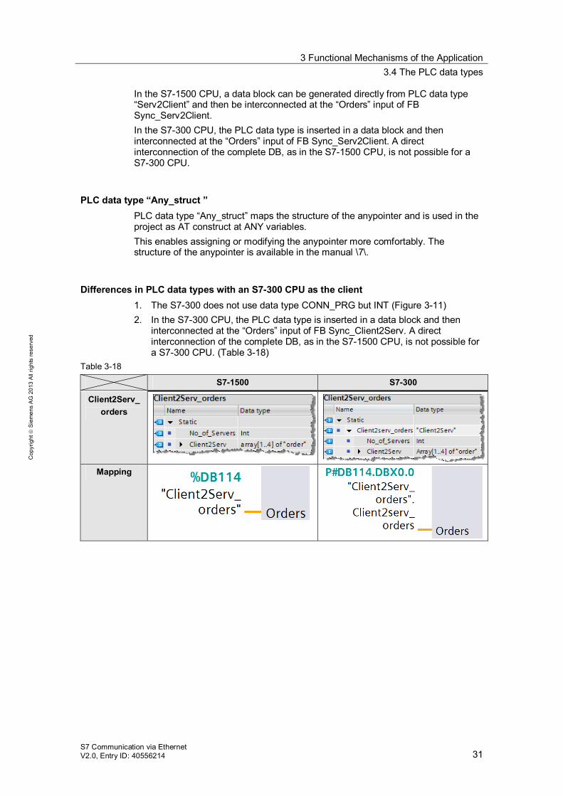
Differences in PLC data types with an S7-300 CPU as the client 1. The S7-300 does not use data type CONN_PRG but INT (Figure 3-11) 2. In the S7-300 CPU, the PLC data type is inserted in a data block and then
interconnected at the “Orders” input of FB Sync_Client2Serv. A direct interconnection of the complete DB, as in the S7-1500 CPU, is not possible for a S7-300 CPU. (Table 3-18)
Table 3-18
S7-1500 S7-300
Client2Serv_ orders
Mapping
4 Startup of the Application 4.1 Hardware configuration
S7 Communication via Ethernet V2.0, Entry ID: 40556214 32
Cop
yrig
ht
Sie
men
s A
G 2
013
All
right
s re
serv
ed
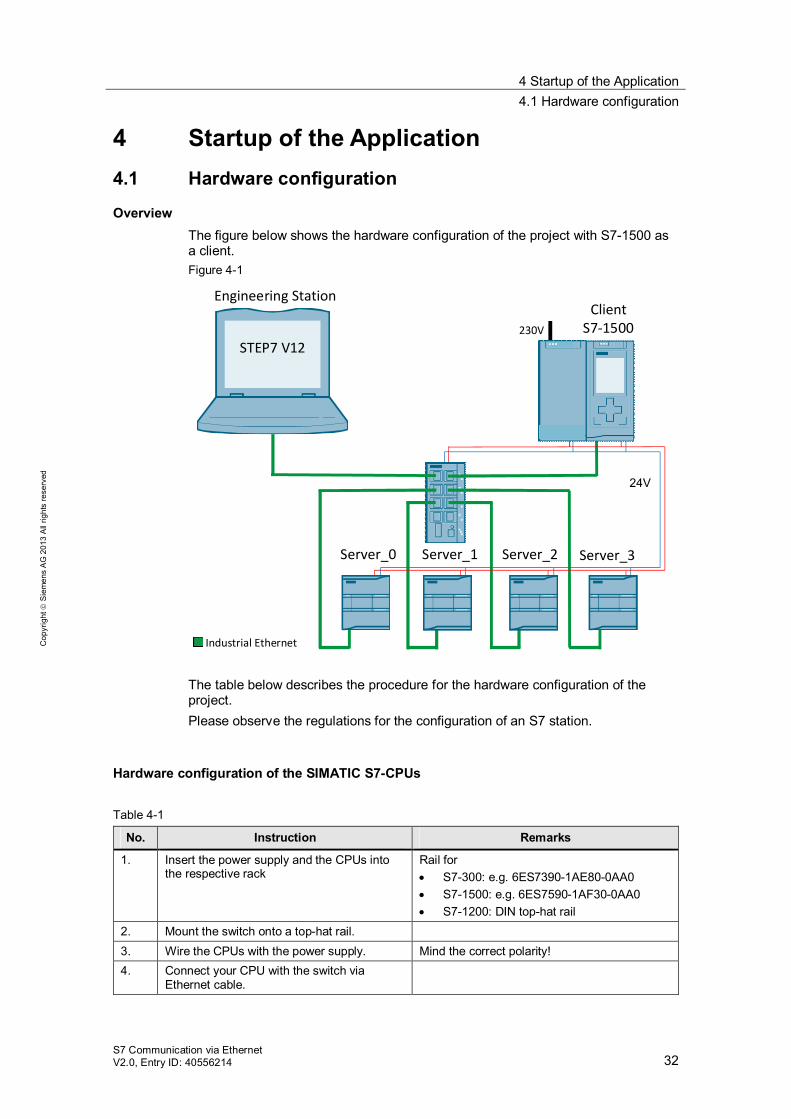
4 Startup of the Application 4.1 Hardware configuration
Overview The figure below shows the hardware configuration of the project with S7-1500 as a client. Figure 4-1
Engineering Station
STEP7 V12
ClientS7-1500230V
24V
Server_3Server_1 Server_2Server_0
Industrial Ethernet The table below describes the procedure for the hardware configuration of the project. Please observe the regulations for the configuration of an S7 station.
Hardware configuration of the SIMATIC S7-CPUs
Table 4-1
No. Instruction Remarks
1. Insert the power supply and the CPUs into the respective rack
Rail for S7-300: e.g. 6ES7390-1AE80-0AA0 S7-1500: e.g. 6ES7590-1AF30-0AA0 S7-1200: DIN top-hat rail
2. Mount the switch onto a top-hat rail. 3. Wire the CPUs with the power supply. Mind the correct polarity! 4. Connect your CPU with the switch via
Ethernet cable.
4 Startup of the Application 4.2 Configuring the hardware
S7 Communication via Ethernet V2.0, Entry ID: 40556214 33
Cop
yrig
ht
Sie
men
s A
G 2
013
All
right
s re
serv
ed
No. Instruction Remarks
5. Connect your power supply with the electricity-supply system (230V AC)
6. Also connect your engineering station with the switch via Ethernet cable.
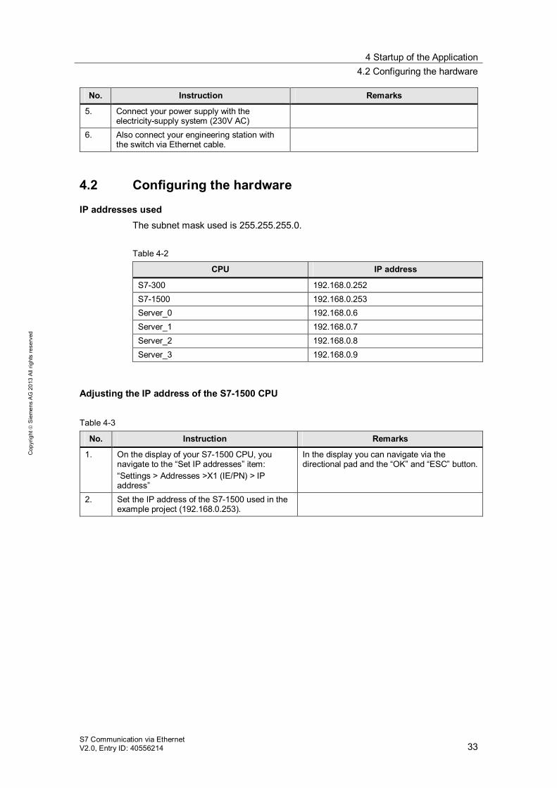
4.2 Configuring the hardware
IP addresses used The subnet mask used is 255.255.255.0. Table 4-2
CPU IP address
S7-300 192.168.0.252 S7-1500 192.168.0.253 Server_0 192.168.0.6 Server_1 192.168.0.7 Server_2 192.168.0.8 Server_3 192.168.0.9
Adjusting the IP address of the S7-1500 CPU
Table 4-3
No. Instruction Remarks
1. On the display of your S7-1500 CPU, you navigate to the “Set IP addresses” item: “Settings > Addresses >X1 (IE/PN) > IP address”
In the display you can navigate via the directional pad and the “OK” and “ESC” button.
2. Set the IP address of the S7-1500 used in the example project (192.168.0.253).
4 Startup of the Application 4.2 Configuring the hardware
S7 Communication via Ethernet V2.0, Entry ID: 40556214 34
Cop
yrig
ht
Sie
men
s A
G 2
013
All
right
s re
serv
ed
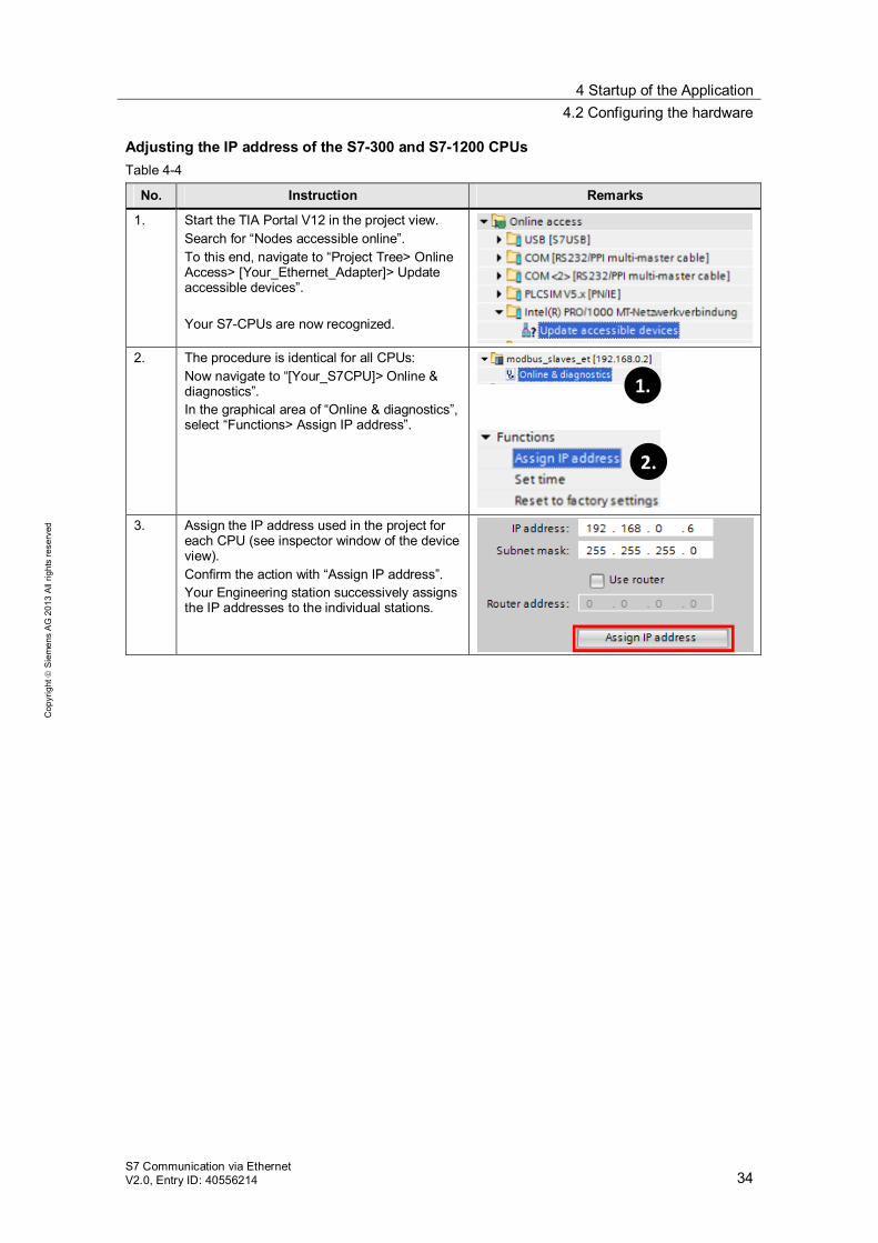
Adjusting the IP address of the S7-300 and S7-1200 CPUs Table 4-4
No. Instruction Remarks
1. Start the TIA Portal V12 in the project view. Search for “Nodes accessible online”. To this end, navigate to “Project Tree> Online Access> [Your_Ethernet_Adapter]> Update accessible devices”. Your S7-CPUs are now recognized.
2. The procedure is identical for all CPUs:
Now navigate to “[Your_S7CPU]> Online & diagnostics”. In the graphical area of “Online & diagnostics”, select “Functions> Assign IP address”.
2.2.
1.
3. Assign the IP address used in the project for
each CPU (see inspector window of the device view). Confirm the action with “Assign IP address”. Your Engineering station successively assigns the IP addresses to the individual stations.
4 Startup of the Application 4.3 Opening and loading the STEP 7 project
S7 Communication via Ethernet V2.0, Entry ID: 40556214 35
Cop
yrig
ht
Sie
men
s A
G 2
013
All
right
s re
serv
ed
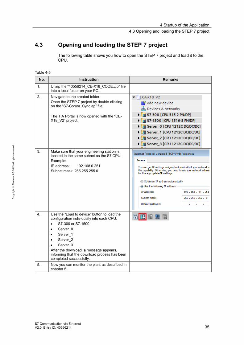
4.3 Opening and loading the STEP 7 project
The following table shows you how to open the STEP 7 project and load it to the CPU.
Table 4-5
No. Instruction Remarks
1. Unzip the “40556214_CE-X18_CODE.zip” file into a local folder on your PC.
2. Navigate to the created folder. Open the STEP 7 project by double-clicking on the “S7-Comm_Sync.ap” file. The TIA Portal is now opened with the “CE-X18_V2” project.
3. Make sure that your engineering station is
located in the same subnet as the S7 CPU. Example: IP address: 192.168.0.251 Subnet mask: 255.255.255.0
4. Use the “Load to device” button to load the
configuration individually into each CPU. S7-300 or S7-1500 Server_0 Server_1 Server_2 Server_3
After the download, a message appears, informing that the download process has been completed successfully.
5. Now you can monitor the plant as described in chapter 5.
5 Operating the Application 5.1 Monitoring the application
S7 Communication via Ethernet V2.0, Entry ID: 40556214 36
Cop
yrig
ht
Sie
men
s A
G 2
013
All
right
s re
serv
ed
5 Operating the Application 5.1 Monitoring the application
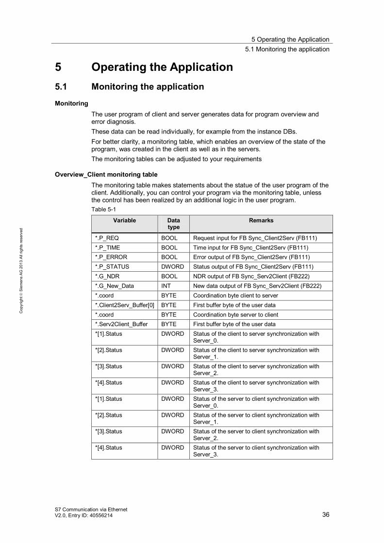
Monitoring The user program of client and server generates data for program overview and error diagnosis. These data can be read individually, for example from the instance DBs. For better clarity, a monitoring table, which enables an overview of the state of the program, was created in the client as well as in the servers. The monitoring tables can be adjusted to your requirements
Overview_Client monitoring table The monitoring table makes statements about the statue of the user program of the client. Additionally, you can control your program via the monitoring table, unless the control has been realized by an additional logic in the user program. Table 5-1
Variable Data type
Remarks
*.P_REQ BOOL Request input for FB Sync_Client2Serv (FB111) *.P_TIME BOOL Time input for FB Sync_Client2Serv (FB111) *.P_ERROR BOOL Error output of FB Sync_Client2Serv (FB111) *.P_STATUS DWORD Status output of FB Sync_Client2Serv (FB111) *.G_NDR BOOL NDR output of FB Sync_Serv2Client (FB222) *.G_New_Data INT New data output of FB Sync_Serv2Client (FB222) *.coord BYTE Coordination byte client to server *.Client2Serv_Buffer[0] BYTE First buffer byte of the user data *.coord BYTE Coordination byte server to client *.Serv2Client_Buffer BYTE First buffer byte of the user data *[1].Status DWORD Status of the client to server synchronization with
Server_0. *[2].Status DWORD Status of the client to server synchronization with
Server_1. *[3].Status DWORD Status of the client to server synchronization with
Server_2. *[4].Status DWORD Status of the client to server synchronization with
Server_3. *[1].Status DWORD Status of the server to client synchronization with
Server_0. *[2].Status DWORD Status of the server to client synchronization with
Server_1. *[3].Status DWORD Status of the server to client synchronization with
Server_2. *[4].Status DWORD Status of the server to client synchronization with
Server_3.
5 Operating the Application 5.2 Scenario A: write synchronization of data
S7 Communication via Ethernet V2.0, Entry ID: 40556214 37
Cop
yrig
ht
Sie
men
s A
G 2
013
All
right
s re
serv
ed
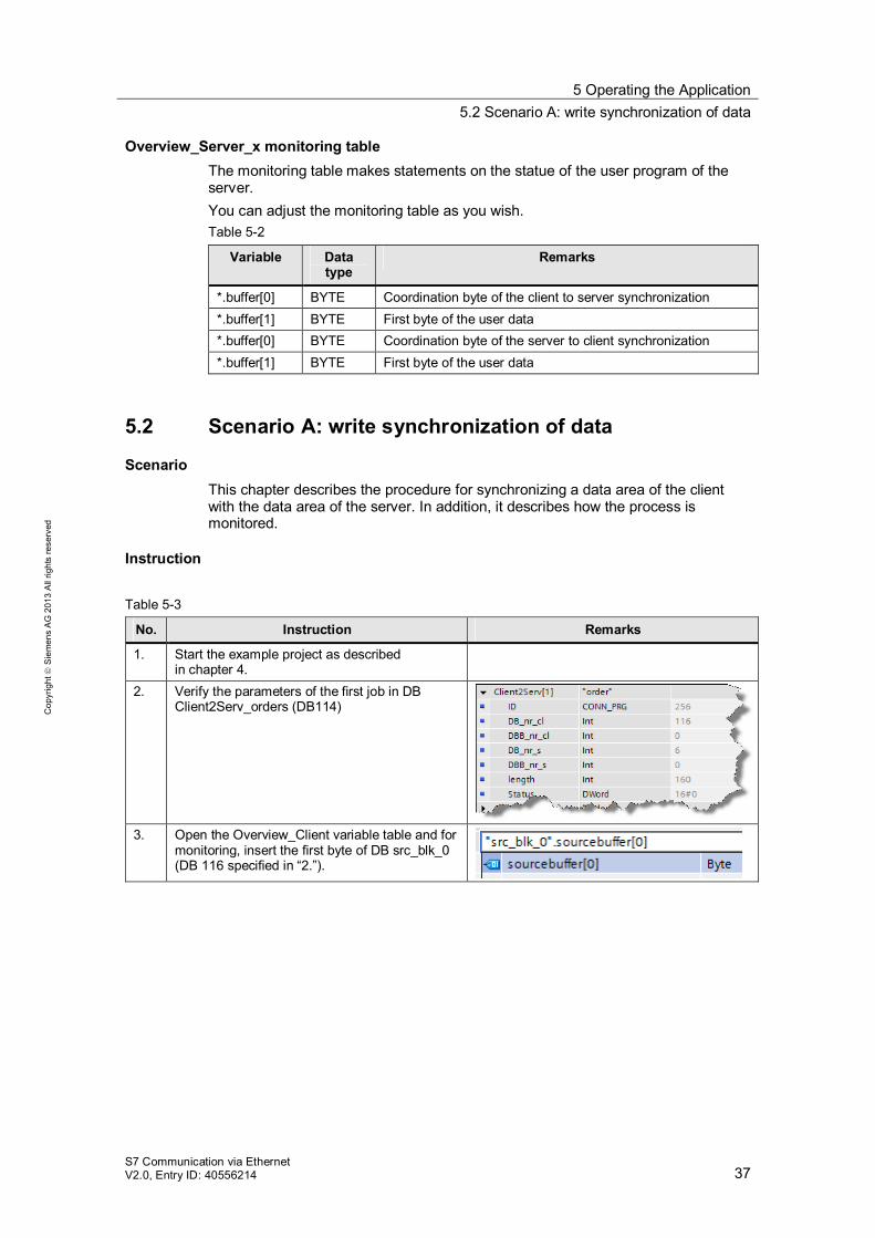
Overview_Server_x monitoring table The monitoring table makes statements on the statue of the user program of the server. You can adjust the monitoring table as you wish. Table 5-2
Variable Data type
Remarks
*.buffer[0] BYTE Coordination byte of the client to server synchronization *.buffer[1] BYTE First byte of the user data *.buffer[0] BYTE Coordination byte of the server to client synchronization *.buffer[1] BYTE First byte of the user data
5.2 Scenario A: write synchronization of data
Scenario This chapter describes the procedure for synchronizing a data area of the client with the data area of the server. In addition, it describes how the process is monitored.
Instruction
Table 5-3
No. Instruction Remarks
1. Start the example project as described in chapter 4.
2. Verify the parameters of the first job in DB Client2Serv_orders (DB114)
3. Open the Overview_Client variable table and for
monitoring, insert the first byte of DB src_blk_0 (DB 116 specified in “2.”).
5 Operating the Application 5.3 Scenario B: read synchronization
S7 Communication via Ethernet V2.0, Entry ID: 40556214 38
Cop
yrig
ht
Sie
men
s A
G 2
013
All
right
s re
serv
ed
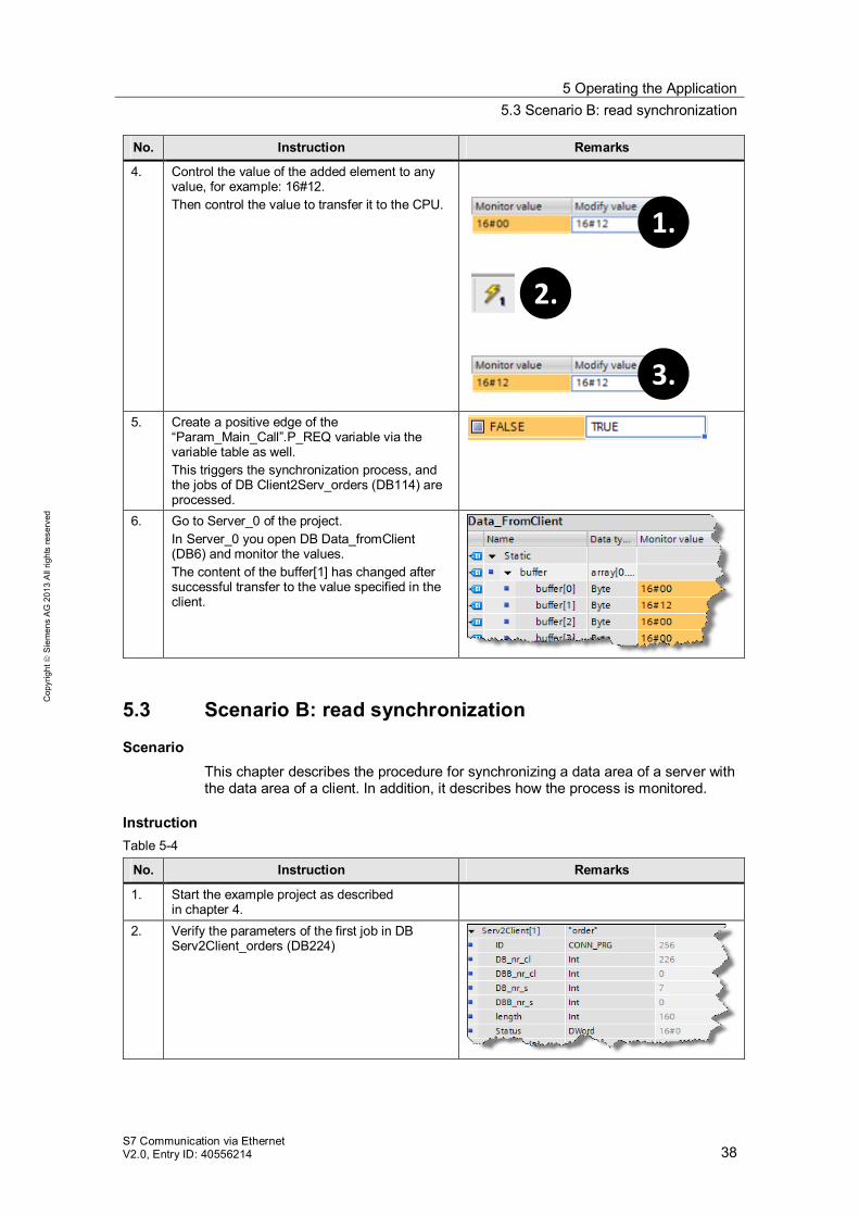
No. Instruction Remarks
4. Control the value of the added element to any value, for example: 16#12. Then control the value to transfer it to the CPU.
2.
1.
3.
5. Create a positive edge of the “Param_Main_Call”.P_REQ variable via the variable table as well. This triggers the synchronization process, and the jobs of DB Client2Serv_orders (DB114) are processed.
6. Go to Server_0 of the project. In Server_0 you open DB Data_fromClient (DB6) and monitor the values. The content of the buffer[1] has changed after successful transfer to the value specified in the client.
5.3 Scenario B: read synchronization
Scenario This chapter describes the procedure for synchronizing a data area of a server with the data area of a client. In addition, it describes how the process is monitored.
Instruction Table 5-4
No. Instruction Remarks
1. Start the example project as described in chapter 4.
2. Verify the parameters of the first job in DB Serv2Client_orders (DB224)
5 Operating the Application 5.3 Scenario B: read synchronization
S7 Communication via Ethernet V2.0, Entry ID: 40556214 39
Cop
yrig
ht
Sie
men
s A
G 2
013
All
right
s re
serv
ed
No. Instruction Remarks
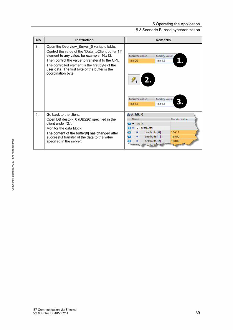
3. Open the Overview_Server_0 variable table. Control the value of the “Data_toClient.buffer[1]” element to any value, for example: 16#12. Then control the value to transfer it to the CPU. The controlled element is the first byte of the user data. The first byte of the buffer is the coordination byte. 2.
1.
3.
4. Go back to the client. Open DB destblk_0 (DB226) specified in the client under “2.”. Monitor the data block. The content of the buffer[0] has changed after successful transfer of the data to the value specified in the server.
5 Operating the Application 5.4 Scenario C: error message for disconnected cable
S7 Communication via Ethernet V2.0, Entry ID: 40556214 40
Cop
yrig
ht
Sie
men
s A
G 2
013
All
right
s re
serv
ed
5.4 Scenario C: error message for disconnected cable
Scenario This chapter describes the behavior of the program if the connection from the client to the servers has been terminated, e.g. due to wrong cabling.
Description Table 5-5
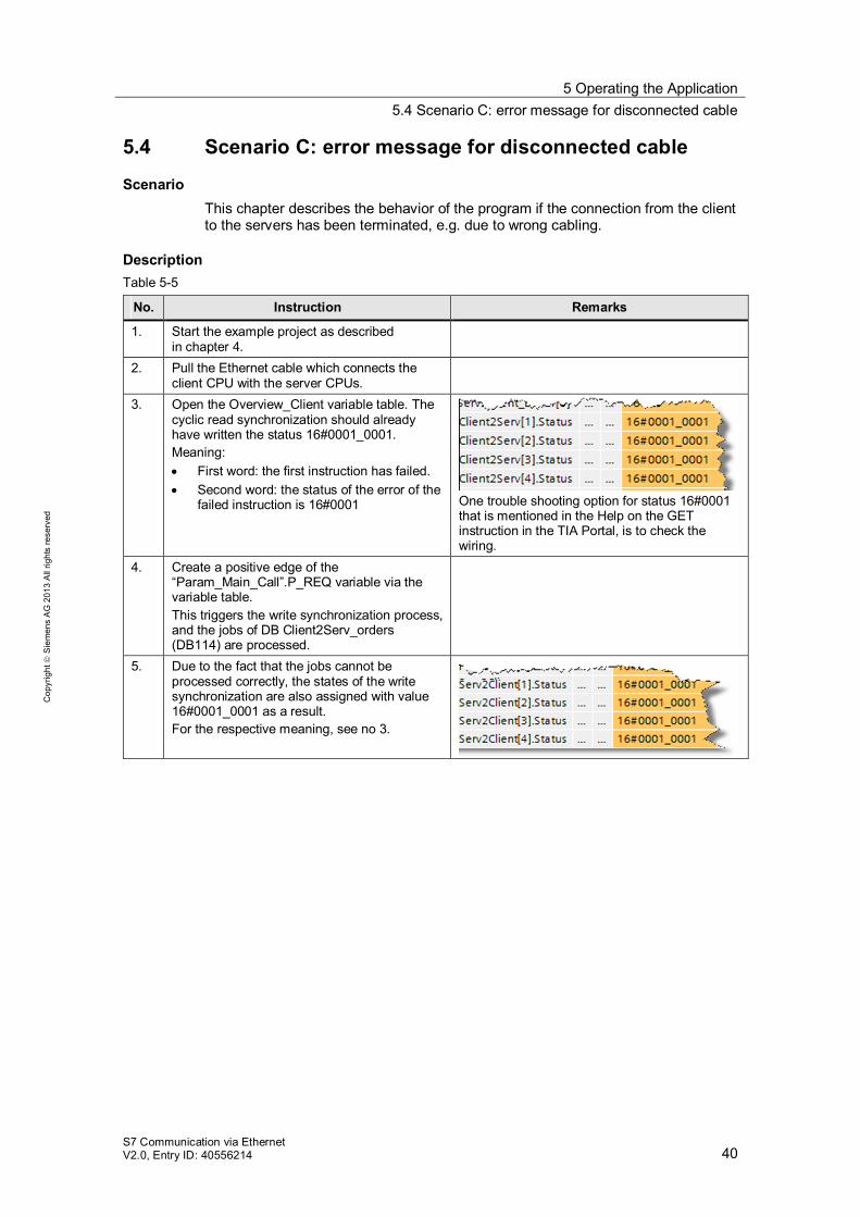
No. Instruction Remarks
1. Start the example project as described in chapter 4.
2. Pull the Ethernet cable which connects the client CPU with the server CPUs.
3. Open the Overview_Client variable table. The cyclic read synchronization should already have written the status 16#0001_0001. Meaning: First word: the first instruction has failed. Second word: the status of the error of the
failed instruction is 16#0001
One trouble shooting option for status 16#0001 that is mentioned in the Help on the GET instruction in the TIA Portal, is to check the wiring.
4. Create a positive edge of the “Param_Main_Call”.P_REQ variable via the variable table. This triggers the write synchronization process, and the jobs of DB Client2Serv_orders (DB114) are processed.
5. Due to the fact that the jobs cannot be processed correctly, the states of the write synchronization are also assigned with value 16#0001_0001 as a result. For the respective meaning, see no 3.
6 Changes at the Project 6.1 Changing the data areas to be synchronized
S7 Communication via Ethernet V2.0, Entry ID: 40556214 41
Cop
yrig
ht
Sie
men
s A
G 2
013
All
right
s re
serv
ed
6 Changes at the Project Overview
If you want to make changes to the STEP 7 V12 project, this chapter provides you with support. The following adjustments are documented. Changing the data areas to be synchronized. Adding a further slave. Ensuring data consistency in the server. Expanding the function of the coordination byte.
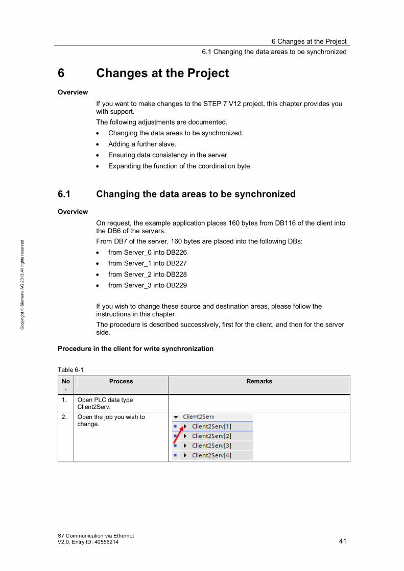
6.1 Changing the data areas to be synchronized
Overview On request, the example application places 160 bytes from DB116 of the client into the DB6 of the servers. From DB7 of the server, 160 bytes are placed into the following DBs: from Server_0 into DB226 from Server_1 into DB227 from Server_2 into DB228 from Server_3 into DB229
If you wish to change these source and destination areas, please follow the instructions in this chapter. The procedure is described successively, first for the client, and then for the server side.
Procedure in the client for write synchronization
Table 6-1
No.
Process Remarks
1. Open PLC data type Client2Serv.
2. Open the job you wish to change.
6 Changes at the Project 6.1 Changing the data areas to be synchronized
S7 Communication via Ethernet V2.0, Entry ID: 40556214 42
Cop
yrig
ht
Sie
men
s A
G 2
013
All
right
s re
serv
ed
No.
Process Remarks
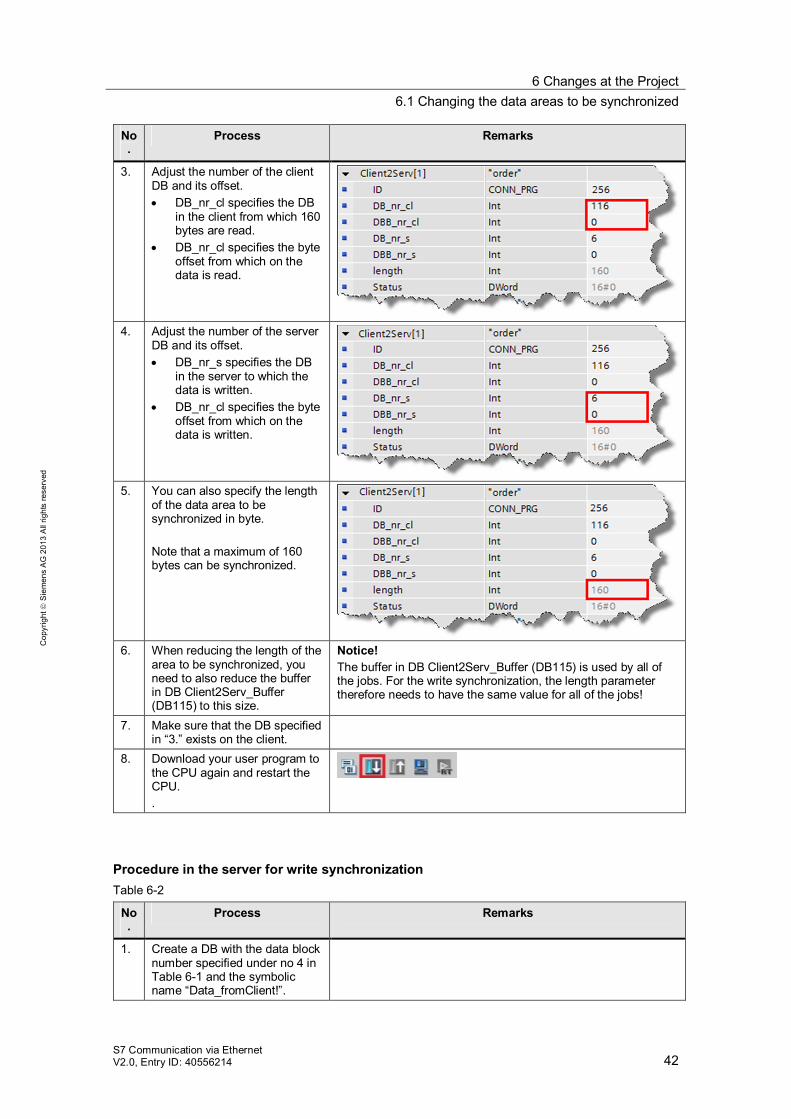
3. Adjust the number of the client DB and its offset. DB_nr_cl specifies the DB
in the client from which 160 bytes are read.
DB_nr_cl specifies the byte offset from which on the data is read.
4. Adjust the number of the server
DB and its offset. DB_nr_s specifies the DB
in the server to which the data is written.
DB_nr_cl specifies the byte offset from which on the data is written.
5. You can also specify the length
of the data area to be synchronized in byte. Note that a maximum of 160 bytes can be synchronized.
6. When reducing the length of the
area to be synchronized, you need to also reduce the buffer in DB Client2Serv_Buffer (DB115) to this size.
Notice! The buffer in DB Client2Serv_Buffer (DB115) is used by all of the jobs. For the write synchronization, the length parameter therefore needs to have the same value for all of the jobs!
7. Make sure that the DB specified in “3.” exists on the client.
8. Download your user program to the CPU again and restart the CPU. .
Procedure in the server for write synchronization Table 6-2
No.
Process Remarks
1. Create a DB with the data block number specified under no 4 in Table 6-1 and the symbolic name “Data_fromClient!”.
6 Changes at the Project 6.1 Changing the data areas to be synchronized
S7 Communication via Ethernet V2.0, Entry ID: 40556214 43
Cop
yrig
ht
Sie
men
s A
G 2
013
All
right
s re
serv
ed
No.
Process Remarks
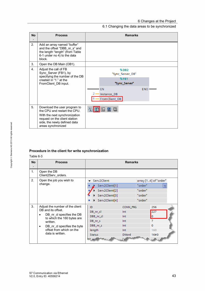
2. Add an array named “buffer” and the offset “DBB_nr_s” and the length “length” (from Table 6-1 under no 4) to the data block.
3. Open the OB Main (OB1). 4. Adjust the call of FB
Sync_Server (FB1), by specifying the number of the DB created in “1.” at the FromClient_DB input.
5. Download the user program to
the CPU and restart the CPU. With the next synchronization request on the client station side, the newly defined data areas synchronized
Procedure in the client for write synchronization Table 6-3
No.
Process Remarks
1. Open the DB Client2Serv_orders.
2. Open the job you wish to change.
3. Adjust the number of the client
DB and its offset. DB_nr_cl specifies the DB
to which the 160 bytes are written.
DB_nr_cl specifies the byte offset from which on the data is written.
6 Changes at the Project 6.1 Changing the data areas to be synchronized
S7 Communication via Ethernet V2.0, Entry ID: 40556214 44
Cop
yrig
ht
Sie
men
s A
G 2
013
All
right
s re
serv
ed
No.
Process Remarks
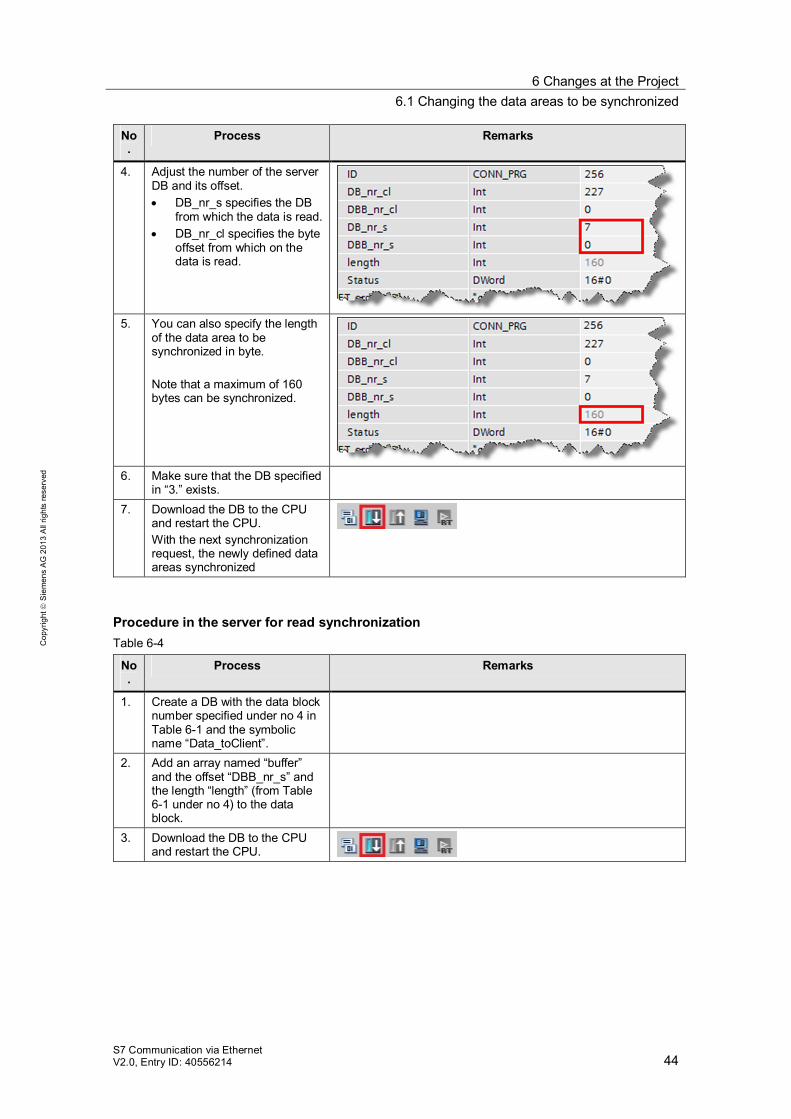
4. Adjust the number of the server DB and its offset. DB_nr_s specifies the DB
from which the data is read. DB_nr_cl specifies the byte
offset from which on the data is read.
5. You can also specify the length
of the data area to be synchronized in byte. Note that a maximum of 160 bytes can be synchronized.
6. Make sure that the DB specified
in “3.” exists.
7. Download the DB to the CPU and restart the CPU. With the next synchronization request, the newly defined data areas synchronized
Procedure in the server for read synchronization Table 6-4
No.
Process Remarks
1. Create a DB with the data block number specified under no 4 in Table 6-1 and the symbolic name “Data_toClient”.
2. Add an array named “buffer” and the offset “DBB_nr_s” and the length “length” (from Table 6-1 under no 4) to the data block.
3. Download the DB to the CPU and restart the CPU.
6 Changes at the Project 6.2 Adding a further server
S7 Communication via Ethernet V2.0, Entry ID: 40556214 45
Cop
yrig
ht
Sie
men
s A
G 2
013
All
right
s re
serv
ed
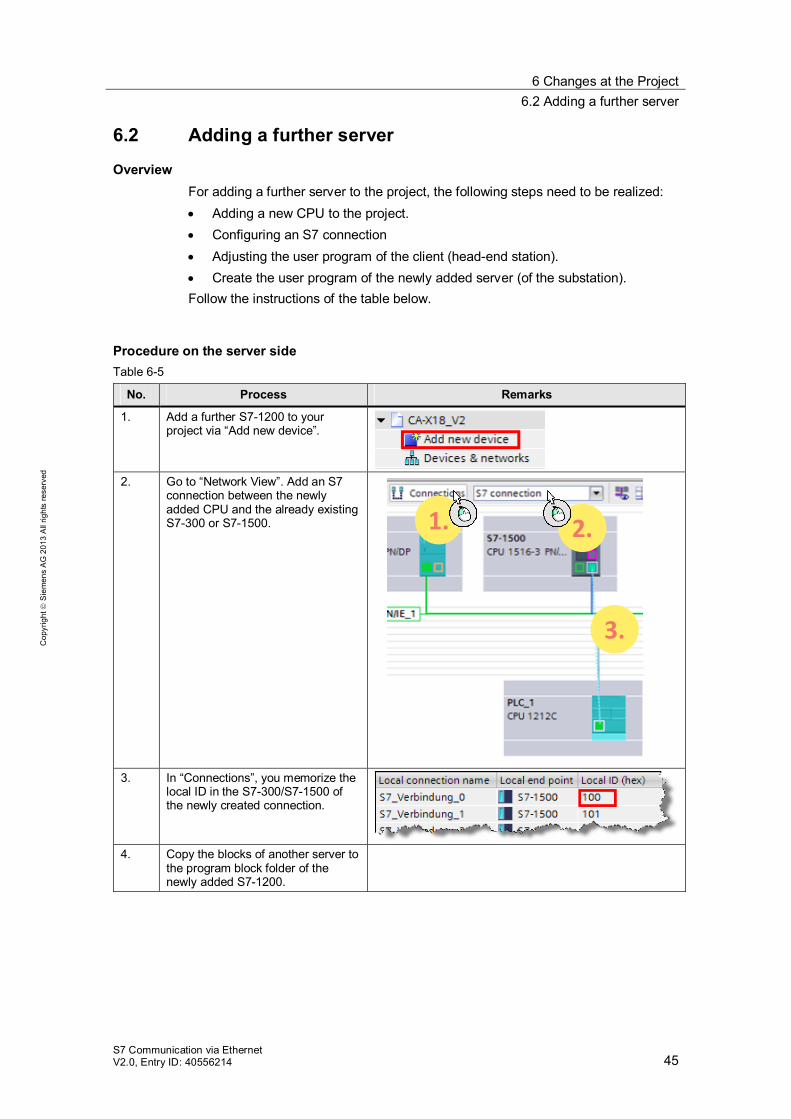
6.2 Adding a further server
Overview For adding a further server to the project, the following steps need to be realized: Adding a new CPU to the project. Configuring an S7 connection Adjusting the user program of the client (head-end station). Create the user program of the newly added server (of the substation).
Follow the instructions of the table below.
Procedure on the server side Table 6-5
No. Process Remarks
1. Add a further S7-1200 to your project via “Add new device”.
2. Go to “Network View”. Add an S7
connection between the newly added CPU and the already existing S7-300 or S7-1500.
3.
2. 1.
3. In “Connections”, you memorize the
local ID in the S7-300/S7-1500 of the newly created connection.
4. Copy the blocks of another server to
the program block folder of the newly added S7-1200.
6 Changes at the Project 6.2 Adding a further server
S7 Communication via Ethernet V2.0, Entry ID: 40556214 46
Cop
yrig
ht
Sie
men
s A
G 2
013
All
right
s re
serv
ed
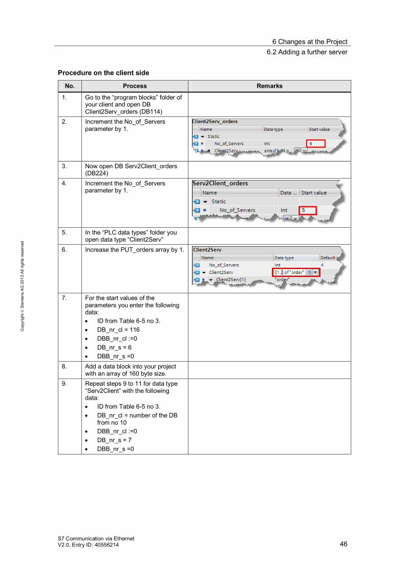
Procedure on the client side
No. Process Remarks
1. Go to the “program blocks” folder of your client and open DB Client2Serv_orders (DB114)
2. Increment the No_of_Servers parameter by 1.
3. Now open DB Serv2Client_orders
(DB224)
4. Increment the No_of_Servers parameter by 1.
5. In the “PLC data types” folder you
open data type “Client2Serv”
6. Increase the PUT_orders array by 1.
7. For the start values of the
parameters you enter the following data: ID from Table 6-5 no 3. DB_nr_cl = 116 DBB_nr_cl :=0 DB_nr_s = 6 DBB_nr_s =0
8. Add a data block into your project with an array of 160 byte size.
9. Repeat steps 9 to 11 for data type “Serv2Client” with the following data: ID from Table 6-5 no 3. DB_nr_cl = number of the DB
from no 10 DBB_nr_cl :=0 DB_nr_s = 7 DBB_nr_s =0
6 Changes at the Project 6.3 Ensuring data consistency in the server
S7 Communication via Ethernet V2.0, Entry ID: 40556214 47
Cop
yrig
ht
Sie
men
s A
G 2
013
All
right
s re
serv
ed
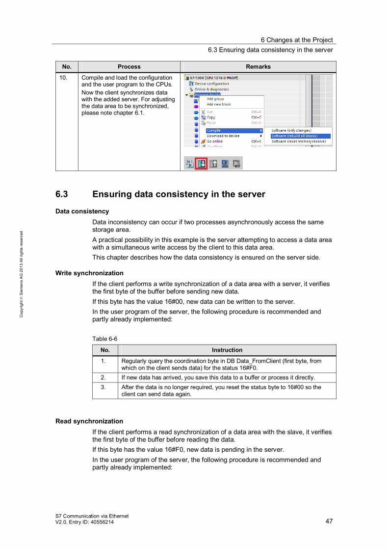
No. Process Remarks
10. Compile and load the configuration and the user program to the CPUs. Now the client synchronizes data with the added server. For adjusting the data area to be synchronized, please note chapter 6.1.
6.3 Ensuring data consistency in the server
Data consistency Data inconsistency can occur if two processes asynchronously access the same storage area. A practical possibility in this example is the server attempting to access a data area with a simultaneous write access by the client to this data area. This chapter describes how the data consistency is ensured on the server side.
Write synchronization If the client performs a write synchronization of a data area with a server, it verifies the first byte of the buffer before sending new data. If this byte has the value 16#00, new data can be written to the server. In the user program of the server, the following procedure is recommended and partly already implemented: Table 6-6
No. Instruction
1. Regularly query the coordination byte in DB Data_FromClient (first byte, from which on the client sends data) for the status 16#F0.
2. If new data has arrived, you save this data to a buffer or process it directly. 3. After the data is no longer required, you reset the status byte to 16#00 so the
client can send data again.
Read synchronization If the client performs a read synchronization of a data area with the slave, it verifies the first byte of the buffer before reading the data. If this byte has the value 16#F0, new data is pending in the server. In the user program of the server, the following procedure is recommended and partly already implemented:
6 Changes at the Project 6.4 Expanding the function of the coordination byte
S7 Communication via Ethernet V2.0, Entry ID: 40556214 48
Cop
yrig
ht
Sie
men
s A
G 2
013
All
right
s re
serv
ed
Table 6-7
No. Instruction
1. Write your user data to DB Data_ToClient from offset 1 on. 2. After the user data has been written to the DB, you set the coordination byte (first
byte of the DBs) to value 16#F0. 3. Regularly query the status byte in DB Data_ToClient for status 16#00. If the byte
has this value, the client has fetched the data and you can start again with no 1.
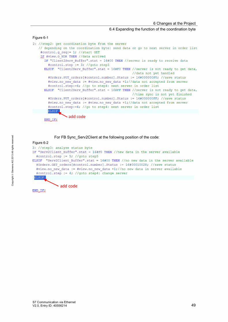
6.4 Expanding the function of the coordination byte
Overview The coordination byte is used in order to coordinate the communication between client and server. If you are adding a further coordination function into your program, this chapter describes where in the program you need to make adjustments.
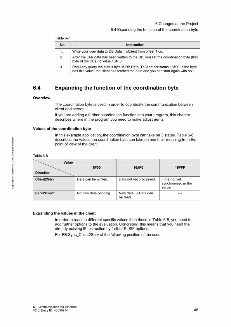
Values of the coordination byte In this example application, the coordination byte can take on 3 states. Table 6-8 describes the values the coordination byte can take on and their meaning from the point of view of the client.
Table 6-8
Value
Direction
16#00
16#F0
16#FF
Client2Serv Data can be written. Data not yet processed. Time not yet synchronized in the server
Serv2Client No new data pending. New data Data can be read.
---
Expanding the values in the client In order to react to different specific values than those in Table 6-8, you need to add further options to the evaluation. Concretely, this means that you need the already existing IF instruction by further ELSIF options. For FB Sync_Client2Serv at the following position of the code:
6 Changes at the Project 6.4 Expanding the function of the coordination byte
S7 Communication via Ethernet V2.0, Entry ID: 40556214 49
Cop
yrig
ht
Sie
men
s A
G 2
013
All
right
s re
serv
ed
Figure 6-1
add code
For FB Sync_Serv2Client at the following position of the code: Figure 6-2
add code
7 Related Literature 6.4 Expanding the function of the coordination byte
S7 Communication via Ethernet V2.0, Entry ID: 40556214 50
Cop
yrig
ht
Sie
men
s A
G 2
013
All
right
s re
serv
ed
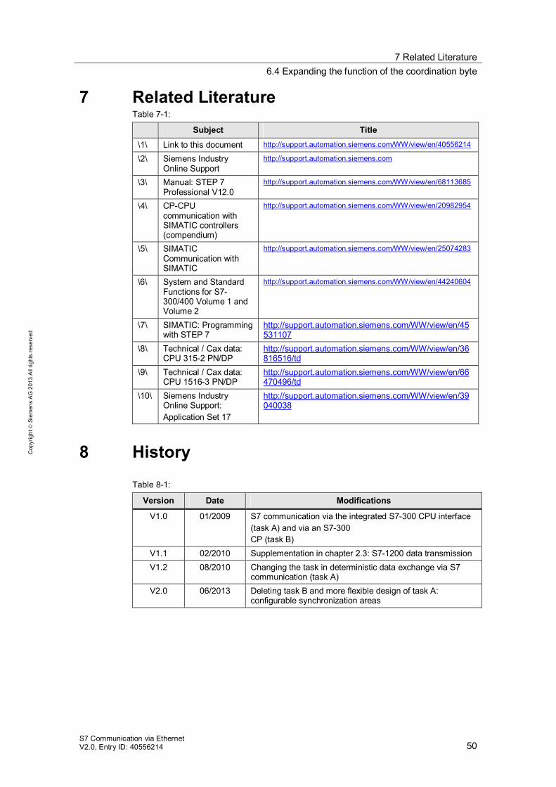
7 Related Literature Table 7-1:
Subject Title \1\ Link to this document http://support.automation.siemens.com/WW/view/en/40556214
\2\ Siemens Industry Online Support
http://support.automation.siemens.com
\3\ Manual: STEP 7 Professional V12.0
http://support.automation.siemens.com/WW/view/en/68113685
\4\ CP-CPU communication with SIMATIC controllers (compendium)
http://support.automation.siemens.com/WW/view/en/20982954
\5\ SIMATIC Communication with SIMATIC
http://support.automation.siemens.com/WW/view/en/25074283
\6\ System and Standard Functions for S7-300/400 Volume 1 and Volume 2
http://support.automation.siemens.com/WW/view/en/44240604
\7\ SIMATIC: Programming with STEP 7
http://support.automation.siemens.com/WW/view/en/45531107
\8\ Technical / Cax data: CPU 315-2 PN/DP
http://support.automation.siemens.com/WW/view/en/36816516/td
\9\ Technical / Cax data: CPU 1516-3 PN/DP
http://support.automation.siemens.com/WW/view/en/66470496/td
\10\ Siemens Industry Online Support: Application Set 17
http://support.automation.siemens.com/WW/view/en/39040038
8 History Table 8-1:
Version Date Modifications
V1.0 01/2009 S7 communication via the integrated S7-300 CPU interface (task A) and via an S7-300 CP (task B)
V1.1 02/2010 Supplementation in chapter 2.3: S7-1200 data transmission V1.2 08/2010 Changing the task in deterministic data exchange via S7
communication (task A) V2.0 06/2013 Deleting task B and more flexible design of task A:
configurable synchronization areas