s 1t1ic) (ijf:1t j3f fundamental study on bending strength
TRANSCRIPT

PERPUSTAKAAN UMP
11111111111111111 0000087370
S
1t1iC)
(iJf:1t J3F
Fundamental Study on Bending Strength of Thin-
Rimmed Helical Gears with Web Arrangements
2O141
DAING MOHAMAD NAFIZ BIN DAING IDRIS

iRfl
1
J. OWN
2.1 *
2.2
2.2.1
2.2.2 Jji'J
2.3 :m 2.3.1
2.3.2 -r92)•
2.3.3 9 J•
2.3.4 1-9J5•
2.4 ±
3* rn t 1 jc7)
3 1
.1 'T
3.2
3.2.1
3.2.2 JJ
3.3 zzm
3.3.1 rJ)rn5fJh 3.3.2
3.3.3
3.3.4 1
) A ^i
.).'I I'Il
%41 co (,l=io, 20, 300)
4 . 1 !l4Z1
4.2
4.2.1
4.2.2 tJj'J
4.3
4.3.1
4.3.2 EJJ Q)f
4.3.3 f7
4.3.4 QTL
5
8
15
17
17
22
23
24
24
26
27
29
37
38
41
43
43
44
45
50
55
60
'I
4.3.5 J ' 1 tJ IL O)J 72
4.3.6 i'iI f,iL' 73
4.4 1 75
5 *
5.1 76
5.2
5.2.1 76
5.2.2 79
5.3
5.3.1 82
5.3.2 J'. 82
5.3.3 J. 85
5A 11±
.'t ;Ic
90
Af 4-f92
93
31111-1 4 ik 111
116
- 11 -

(Nomenclature)
a :rP,NTEM (Center distance)
b : ikt (Face width)
r- (Web thickness)
d : R (Reference diameter)
da : (Tip diameter)
db : (Base diameter)
E : - -' 7' *1L (Young's modulus)
F, RJJ)J (Circumferential load)
F1 : (Bending fatigue limit circumferential load)
L : -1i (Length of path of contact)
it : y Y (Transverse backlash)
At : y -' (Transverse base backlash)
Mn (Normal module)
m t : *E- —iI' (Transverse module)
N U (Number of load cycles)
Phi : y (Transverse base pitch)
r : (Reference radius)
ra : R1 (Tip radius)
rb : 94M R (Base radius)
1. 9 AJ (Rim thickness)
X : (Coordinate axis)
y : )*I (Coordinate axis)
z : i1k (Number of tooth)
() (Number of tooth of driving gear)
Z2 : %i) i*c1)1 (Number of tooth of driven gear)
aa : (Tip angle)
j (Normal pressure angle)
at : IiM i$JIf (Transverse standard pressure angle)
awt 9- 1 'flE)JI (Pressure angle at the pitch cylinder)
180 R MIN ±Oa UL (Helix angle on pitch cylinder)
A 1I (Base helix angle)
' (Transverse contact ratio)
6,6 -i " (Overlap ratio)
Ey (Total contact ratio)
C : (Tangential angle)
- 111 -

or : &5GJJ (Root stress)
5iJJ (Compressive root stress)
I 15ZJJ (Tensile root stress)
(Suffixes)
I: Ib () ffi* (Driving gear, test gear)
2 : (4) i* (Driven gear, supporting gear)
c : )I (Compression)
max JOz (Maximum)
mm : /J\ (Minimum)
solid : {*i' (Solid gear)
t 91 , * i (Tension; transverse section)
- iv -

'&*LS& 1- PDB
-C /M" <J k <
:, !)
uu,
ft 6b
ft±,1C "13t:), L+Z
(9,
9M4 N,' - 7L/ N <'J'FH
gp - -o \ 53 7 4 fl.8)
1 j'VC1i \ 1.9)(1.12)
H 1.13)(1.15)
U-CILL Z cJ:
VC 1i. 'J\I1 -g id• /J\ "6119, L, -C, BEM FEM -J
i*
U, Bibel Handschuh 1.2O)
9 J Q)J, Lewicki I21) 9 JQ)-\
Uf cfqi^ t,
*t U(9,
tbL7.
gf< (9 nil
(9 3pE1.22)
U, Wellauer 1.23)(124)
" - c *dtY Niemann (I.25)(1.26)
, fl:- i: -v . r T127),
1.28)(1.31) -
. .
-, rn t CI
VC1i \. -,
- 1 -

(1.29),(1.31)
(1.36)(l 37)
c8.13j(I.32)(1.38)-1.39)
job i1 • •
1.32), (1.39)(1 .45)
irn'J
(1.46)(1.53)- \iJU
1) j<
_rc< 7 1) J1.4)(1.21) 9 .AJ 9 i5
(FEM) :ztb
M0t 7
<JjtL7.
1.54) 1.55) ,j . /j\ft . 11
3D-FEM
}tF-°I 'tJJU 'LC l ' ' t, American Gear Manufacturers Association
Lt 6 T,
O)l'L 9 Jz
Q)9J
=2O0 f ur U-c,
)LJ U-, c jQ),
1 ( 4) , 9 JJ 3OU-(Y7 7J LCY
, =2000
U,jJ0)Th,
L )L, 1*
JJ1,
7.
-2-

U=1O13O0 *
t UEJJ IJ U, t c7) ,
:, wt . rnico WiJ
rnrr U, 'J : 1* U
9 J . 1
EL
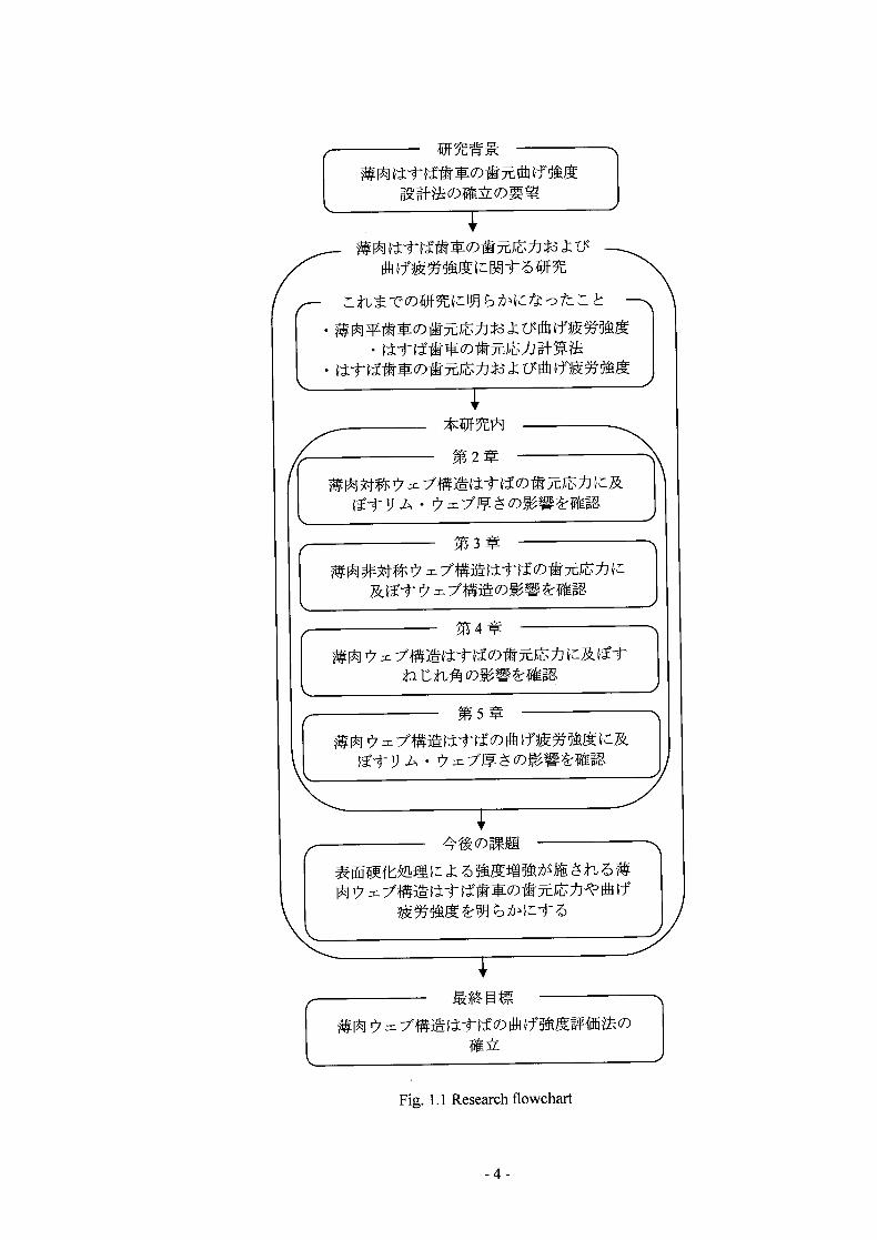
1.1
-3-
1 -
QJf
• Jj:3
IL (--L j7
L-J .l)•
Ij] 1 JD
PUR
Fig. 1.1 Research flowchart
-4-
2.1 *
')J <,
< M1 \ 7; . U U, I TIM J:t Ilk
'. i_), C1i\ \ 5 :4i . Q)i,
2.3H2.7) -vc 9, WE \ U WIJ
*Q)0t
Jj9
(FEM)
U, Q))f
W Le
Lj/) 9 L7J ,
j- 1) tJ Q:-c : Ut-Lt **, 2Q)9
5jQ)Th, jk i'z
1 :
2.2
2.2.1$
= 200, rnz1 iz2 = 36/24, iJb = 30 mm135 mm,
UtL8O = 20m : 't
S45C . () 5 Lij (*, i) *, m, a -3
Z2 24 )), rnu*< b35mm
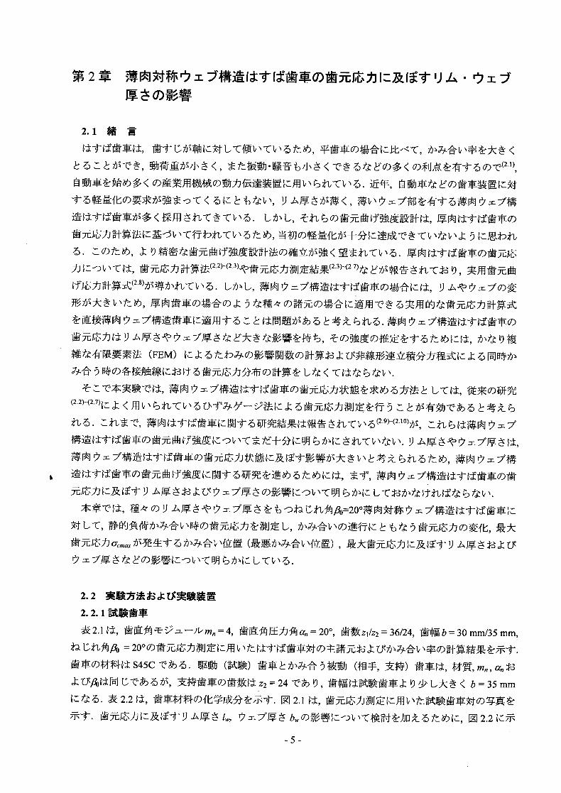
2.2 tt, tQ)I j. 2.1
A TV L^z l, tJ bUj, 1 2.2
-5-

5jL ^ 900 ci-- H'1U, I1 2.2 bl>' l J1'
Q)ii 9 5 2.2.
24i t 1. Q), Q)iIH JIS4 (VT
Table 2.1 Dimensions and calculated results of test helical gear pairs
Normal module Mn 4
Normal pressure angle an 200
Number of teeth z1 /Z2 36 / 24*
Face width bmm30/35*
Transverse backlash f tm 640
Helix angle fib 200
Transverse module m1 4.257
Transverse pressure angle at 21.1730
Base helix angle fib 18.7470
Reference diameter d, mm 153.242
d2 mm 102.162*
Tip diameter d,,, mm 161.242
d,,2 MM 110.162*
Base diameterdblmm 142.896
db2mm 95.264*
Transverse base pitch Pbi 12.470
Transverse base backlash fbi 596.796
Pressure angle at the pitch cylinder
, 22.0330
Center distance a mm 128.511
Length of path of contact L 16.815
Transverse contact ratio 1.348
Overlap contact ratio ep 0.817
Total contact ratio e, 2.165
Material S45C
Accuracy JIS Grade 4 (N8)
Driven (Mating / supporting) gear
Table 2.2 Chemical compositions of gear material(mass %)
Material C Si Mn P S
F 0.42' 0.15— 0.60---'0.030 0.035 S45C
0.48 0.35 0.90

(a) Test gear (b) Supporting gear
Test gear
(c) Gear pairs in mesh
Fig. 2.1 Photographs of test gear pairs used in measurement of root stresses
7-
T3
Part PA2
T T2
0) 0)
90° Pa PO
Gear part sign P0 PA I PA2 I PA3
Gear structure Solid Symmetric web
Rim thickness mmoo 2mn** 1.5 Mn
Web thickness b mm - 7.5 5
*00: solid gear **Mn: normal module
Fig. 2.2 Shape and geometry of test gear (With symmetric web)
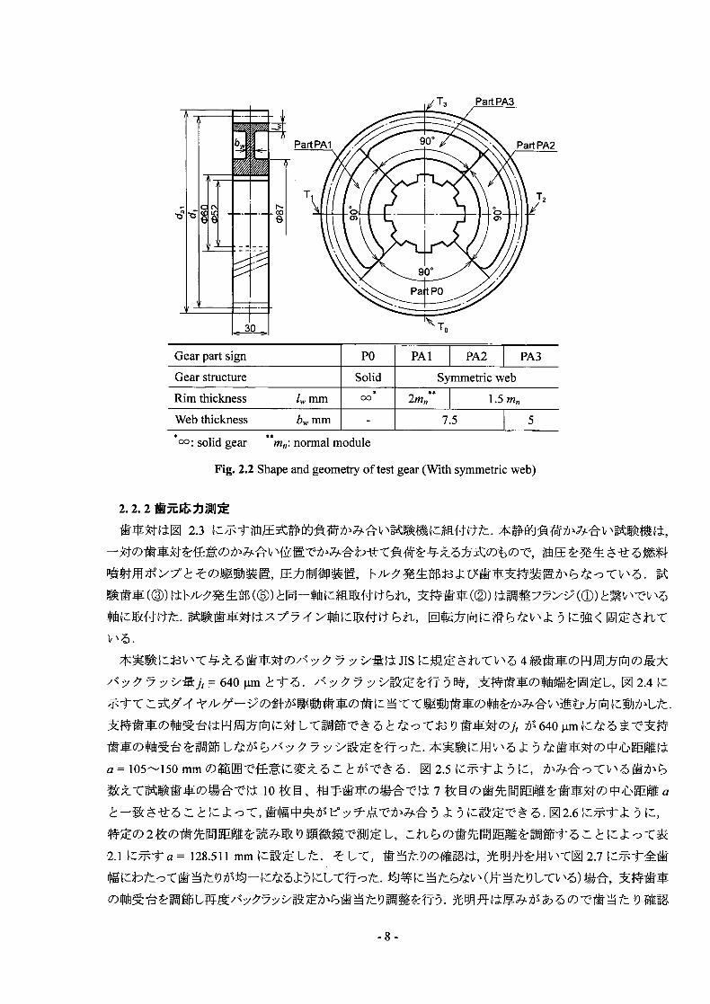
2.2.2iZi]
2.3 *ll1tt.
! *(®) M(®) 1©) 7(©) v' l:j- /. 1frt i, 9 <
'/J,640jtm i yxqf)H#, I12.4L
64Ojm 4
a = 105-150 mm . J 2.5 JtJZ
10H 7
z ,
2.1ja z 128.511 mm1Uit. L/C, WjifLMAX-4J:, 2.7
) 9
-8-

I hydraulic pump
Fixing flange © Test gear © Supporting gear ® Torque pick-up © Torque generator
5 , - C j 9 1Ct t
t U fiMi. )ftW< *tit)
q-5 Uti.
2.8 7Ft 9
tO= 300 (0:
0) Hofer f' —' 0.2mm 6mm 5t
-v 1,5 9 3 m vPA 9 ) LC, FiJJJ F1/b = 196, 392, 588 N/mm
Ut1I,
9 2.2 0--PA3)0Y T0
--T3 2.9N:, ±_ 0) (UMM ©—UTI N:PMEA 10 0){ 20 MMAL Uft).
U, (P) 5. M2.10 N:, * It
5 - 7. 5 , ''* U FiL'
(Z)
JII \,
z {9 fWL-. U, 11:
2.11 ,
2.11 5, UMM
, JJ = 20°4øJ
Fig.2.3 Static load test machine
S

Pick gauge
gear
Fig. 2.4 Photograph of setting of backlash
Center distance
Test gear (zi=36)
©, ©, : Tooth number
0: invaa - zflVcj
Fig. 2.5 Schematic illustration of setting of meshing position (z1 /z2 = 36/24)
-10-

Reading telescopeScale
Test gear Supporting gear
t te
Fig. 2.6 Photograph of setting of pitch point meshing position
upporring gear 1L
t te
(a) Red lead thickness is thick
(b) Red lead thickness is thin
Fig. 2.7 Photograph of tooth bearing adjustment by using red lead
- 11 -

(r'imrrssive
Hofer's critical section
No. 1, 2, 3, 4, 5: Strain gages
Fig. 2.8 Positions of strain gages
1W
Pbf 12.47 mm (P)
epbf=l6.8lmm
Beginning of End of engagement engagement
(Root) (Tip)
Fig. 2.9 Contact lines on the plane of action used in measurement of root stresses
-12-

Torque initiation part
Supporting gear (driven gear)
I
L
I
, V, Strain measurement 1
device
Test gear (driving gear)
Hydraulic pump
Fig. 2.10 Photographs of static bending test machine and peripherals
Dial gauge
Fig. 2.11 Photograph of tooth bearing by means of root stresses measurement of Part P0 (Solid gear)
- 13 -
Start
Preparation of test gear (Line scribing, strain gages bonding etc.)
I Setting of pitch point meshing Gear pairs assembly I position and tooth bearing
Setting of backlash], I
NO
YES
I_
rMeasurement of center distance a ]
YES
ITooth contact marking check by using red lead
Equal along
trace
YES - Tooth bearing by means o measurement of root stres
Root stress measurement of solid helical gear part during static load test (Circumferential load F,/b = 196, 392, 588 N/mm)
Comparison of measured and calculated root stress by Kubo-Umezawa method
Measured Calculated NO Adjust the position of supporting gear pedestals
YES
Root stress measurement of thin-rimmed helical gears part during static load test (Fe/b 196, 392, 588 N/mm)
End
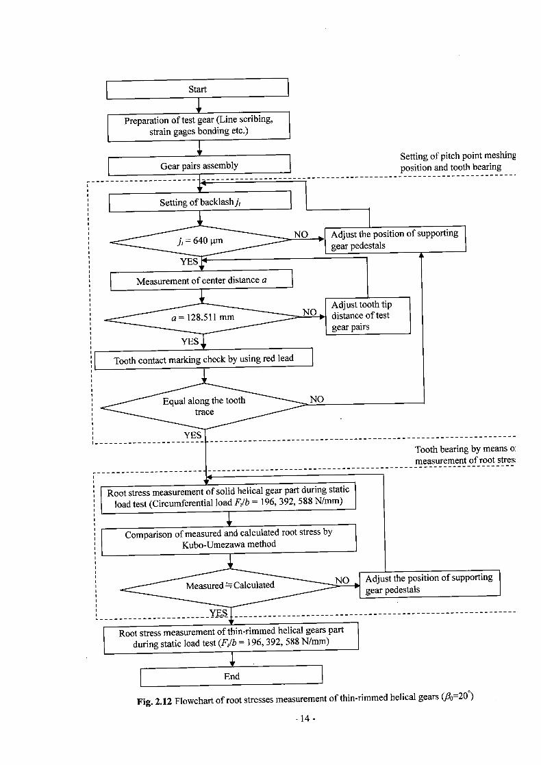
Fig. 2.12 Flowchart of root stresses measurement of thin-rimmed helical gears (,0020°)
Adjust the position of supporting gear pedestals ]
Adjust tooth tip distance of test gear pairs
-14-

2.3 JZU
2.3.1 Ittc)Zi]
F1 2.13, 2.14 , F1 2.2 Part P0 (—I*i') iLR)JJ F1/b = 196, 392, 588 N/mm
(b=30mm: *)
UC7Th. 2.13, 2.14 fo),
-D -t:. 2.2) jy
Acute side (A. side), Obtuse side (Ob.
side) LC1I' . . 1 2.13 , 9
FI 2.13 Jz 9 Ob. side i 1 f U
M 2.14 It, 'Jz 10 iQ)E
LI 2.14 1 9 fflIJ f
U
5Z JJ1 ,< 2
(0. P.: Outer point) ^2
UU,
t1f'
9 .A, E7 I1 2.14
(>2) U, acmg 1'i:W 1i) [i
(P)] M 2.9
Qy;;, Part PO 2.13
t)L Ut, Pa1.tPA1*PA3
- 15 -

-800 fi0=20 [I,= b/b = 11 Trailing side Calculated -600
-400Solid gear /(Ob.side)
- FIb = 196N/mm -200 I- 392N/mm -800
m I - 588N/mm -600 Measured -400 ________ . F/b = 196N/mm
a -200 j I • 392N/mm - 800 • 588N/mm -600 A E
Middle A. side: Acute side of face width -400 ________
•1 • Ob.side: Obtuse side of face width
-200 Gn
5 -800 A: Beginning of engagement -600 B: End ofengagement -400 P: Pitch point
200• a • • • - P• Transverse base pitch
-800 r I -600
Le ading side I
-
-200 - • - - •
(A. side)
p
Positions of engagement 3
Ptg tooth pairs No. of me
Fig. 2.13 Calculated root stresses and measured root stresses after
tooth bearing by using red lead (P0, flo=20°)
800 1/ 20 [ç= , b./b = 11 Trailing side Calculated 600 Solid gear /(Ob. side) -400
-
- F1 1b 196N/mm 200 r • I 392 N/mm 800 -800 588 N/mm
-600 Measured -400 • F1 /b 196 N/mm
a 200 ____________ 392N/mm -800 E 588N/mm
b'-600
(0 -400E
Middle Aside: Acute side offaCewidth -200 U - Ob.side: Obtuse side offace Width -800
- A: Beginning of engagement -600 B: End of engagement -400 P: Pitch point -200 _________ Transverse base pitch -800 r 4: Position of max. stress -600 Ocmax Leading side -400 ______ (A. side) -200
Positions of engagement
Ptmeg tooth paira No.of
Fig. 2.14 Calculated root stresses and measured root stresses after tooth bearing by means of measurement of root stresses (P0, ).=20°)
-16-

2.3.2 (Z&(t1)1
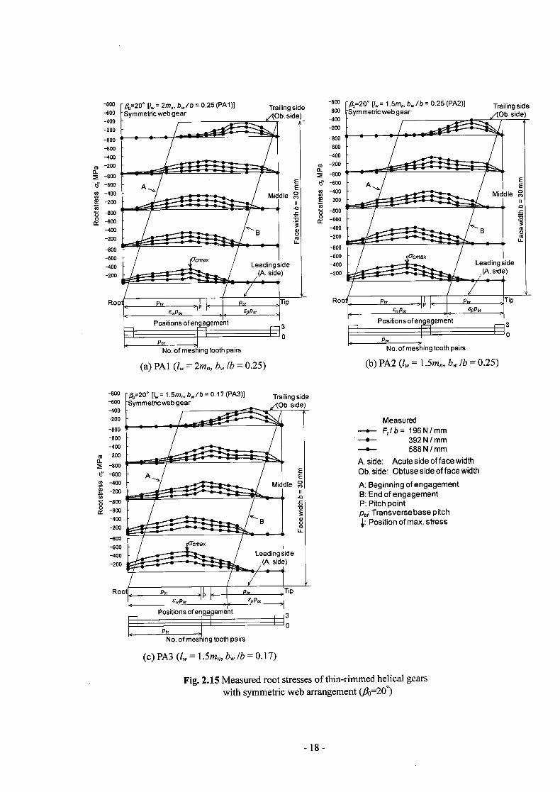
I1 2.15 , 9 1 = 2m,, (ma : ¶7rtN b lb = 0.25 (b: i, II 2.2
1) PartPAl) , l 1.5m, blb = 0.25, 0.17 (11 2.2 ci) PartPA2, PA3)
., F1/b = 196, 392, 588 N/mm 9 iEJjQ)
11 2.14, 2.15 '9, Wii 9
im rns ' <
9 J1k <'j)m
1 2.15(b), (c) 9, li 5 Q', Il 2.15(a
9 9 1)7. il 2.15 c1 Q) ,
l\4j (P)Z '9 U 1 (P clZ '9 i° J) PA2
50PA3 P 19 t-tU-CJVN UR-DfL7))- 9;^- 1^- V fA-L Wt (P J, '9 n,, ft N 4E A
I?. PA2 U PA3 O) 9 tWl
< ?J . PAl, PA2 131UPA3
I1 2.9 ci)1 hQ)*© (PAl) © (PA2,PA3)
2.3.3 *IZt1)b
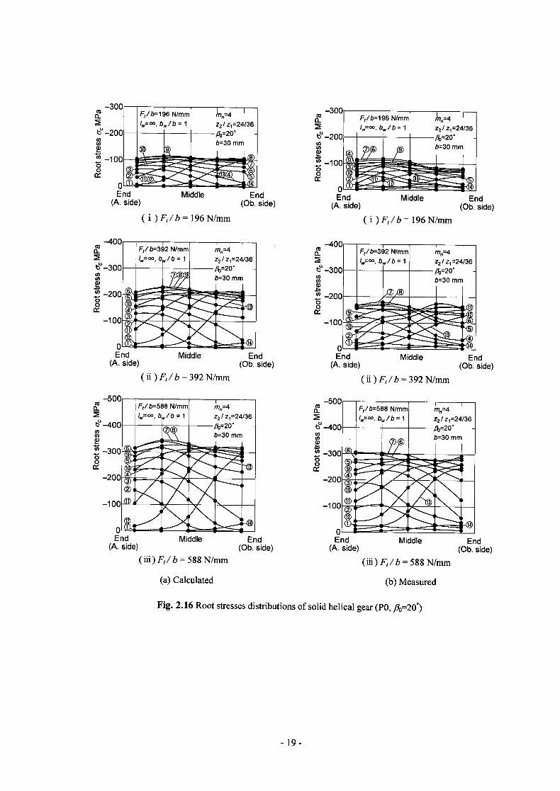
I1 2.16 , II 2.14 Fe/b = 196, 392, 588 N/mm &ci) P0
. M2.17, 2.15 1lF1/b= 196,392,588N/mm1 PA1,PA2LtYPA3
i2.16,2.17
II 2.16, 2.17 2.16,2.17Q ft
*ci) p {Q)W
L12.17 J, 9, 91J, 1) J4-,
It., , Ob.
side
-17-
Positions of engagement
Pt F No. of meshing tooth pairs
(a) PAl (l = 2m, b lb = 0.25)
Positions of engagementri3
Pt No. of i tooth pairs
0
mesh
(b) PA2 (l = 1.5m,, b lb = 0.25)
80 1f. =20 [IU,= 2m, b/b = 0.25 (PAl)] -600 FSymmetncweb gear -400
-200
-800 S S S
-600
-400
200 CL
-800
-600 A -400
-200
-800
-600
-400
-200
-800
100 Ocmax
-400
-200 F-
Trailing side-800 /3=20 [ç = 1 .5mg, b lb = 0.25 (PA2)] Trailing side
,10b.de)600
-400Symmetncweb gear b. side)
-200
-800
-600
-400
ca -200
-800 E E A
E E
Middle-400 Middle -200
- .0 - S-- • U)-800
_____________________________________
2 IX -600 :9
v—-400 B LL
-200 U) Li
-800
-600 cycmax
Leadingside -400 Leadingside (A. side) -200 - (A. side)
800 / =20 [i 1 .5m0, b/b = 0.17 (PA3)] Trailing side 600 Symmetricweb gear 10b. side)
-400
-200/ Measured
-800
- S S
—.— FIb= 196N/mm -600 . --- 392N/mm -400 -.-- 588N/mm -200
Aside: Acute side of face width -800
-600E
A EOb.side: Obtuse side of face width
-400 Middle A: Beginning of engagement -200 B: End of engagement -800 P: Pitch point -600
pbf Transverse base pitch -400 B 0 4: Position of max. stress -200 Co
LI..
-8
-600
00Ocmax
-400 Leading side -200 (A. side)
Positions of engagement 3 LI0
No. of meshing tooth pairs
(c)PA3 (1, = 1.5m,blb0.17)
Fig. 2.15 Measured root stresses of thin-rimmed helical gears with symmetric web arrangement (J3o20°)
-18-
Lp.l____ A
LIIIII!
11,
End Middle End (A. side) (Ob. side)
(i)F,/b= 196N/mm
(U F1/b196 N/mm I=°° ' b,,/b= 1 z2/z1=24/36
d-200 -
8 b=30 mm 6
-100 o
11
End Middle End (A. side) (Ob. side)
(i )F,/b= 196 N/mm
LJ" r _ Is]
I
m=4 cc F/b=392 N/mm m=4 z2 / z1 24/36 /,,=oo, b/b = I z2/ z1=24/36
-30O -fi2O0 b=30 mm b=30 mm
-20C--- Jj IcT-r k —ioc
(U
Cl)
0 0
End Middle End (A. side) (Ob. side)
( ii) F,/b = 392 N/mm
500 I
F,/b=588 N/mm m=4 Ir, 00 , b/b = 1 z2/ z1=24/36
WO----J^8--Ao=20*
b=30 mm
-1
End Middle End
(A. side) (Ob. side)
(ii)F/b = 392 N/mm
-500 I CU I F,/b=588 N/mml
MO
=4
I i000,b,.,/b=1 z21z124/36 I
t-400 fl0=2O
I I I b3Ommma U) a) I I -300
0 0 Ix ras
-100
.i—t_S—t-----I_I 01 - j End Middle End End Middle End
(A. side) (Ob. side) (A. side) (Ob. side) (iii)F,/b588N/mm (iii)F,/b588N/mm
(a) Calculated (b) Measured
Fig. 2.16 Root stresses distributions of solid helical gear (P0, /30=20)
-19-