ruska model 7710 air data test set user’s manual · ruska model 7710 air data test set user’s...
TRANSCRIPT
RUSKA MODEL 7710
AIR DATA TEST SET
USER’S MANUAL

RUSKA MODEL 7710 AIR DATA TEST SET
OPERATORS MANUAL
RUSKA INSTRUMENT CORPORATION 10311 WESTPARK DRIVE, HOUSTON, TX. 77042
(713) 975-0547 FAX: (713) 975-6338 e-mail: [email protected]
Release: 7710-1D00 Revision: E
Date: 10/15/02
-1-
WARRANTY
Ruska Instrument Corporation warrants its products to conform to or exceed the specifications as set forth in its catalogs in use at the time of sale and reserves the right, at its own discretion, without notice and without making similar changes in articles previously manufactured, to make changes in materials, designs, finish, or specifications. Ruska Instrument Corporation warrants products of its own factory against defects of material or workmanship for a period of one year from date of shipment.
Liability of Ruska Instrument Corporation under this warranty shall be limited to replacing, free of charge (FOB Houston, Texas), any such parts proving defective within the period of this warranty, but will not be responsible for transportation charges or consequential damages.
This warranty is not made for products manufactured by others which are illustrated and described in Ruska catalogs or incorporated in Ruska products in essentially the same form as supplied by the original manufacturer. However, Ruska Instrument Corporation agrees to use its best efforts to have original suppliers make good their warranties.
-ii-
DISCLAIMER
No representations or warranties are made with respect to the contents of this user's manual. Further, Ruska Instrument Corporation reserves the right to revise this manual and to make changes from time to time in the content hereof without obligation to notify any person of such revision.
TRADEMARK NOTICE
is a trademark of Ruska Instrument Corporation.
Trademarks or tradenames are subject to state and federal laws concerning their unauthorized use or other infringements. The fact that the product marks or names in this manual do not bear a trademark symbol does not mean that the product name or mark is not registered as a trademark or tradename. Any queries concerning the ownership or existence of any trademarks or tradenames mentioned in this manual should be independently confirmed with the manufacturer or distributor of the product.
-iii-
REVISION NOTICE
RELEASE REV. NO.
DATE DESCRIPTION
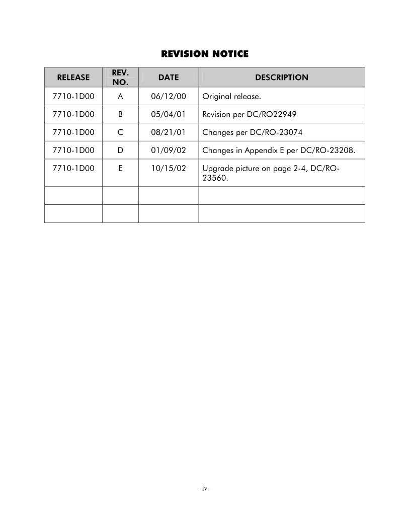
7710-1D00 A 06/12/00 Original release.
7710-1D00 B 05/04/01 Revision per DC/RO22949
7710-1D00 C 08/21/01 Changes per DC/RO-23074
7710-1D00 D 01/09/02 Changes in Appendix E per DC/RO-23208.
7710-1D00 E 10/15/02 Upgrade picture on page 2-4, DC/RO-23560.
-iv-
Introduction
This technical manual provides operating instructions for the Air Data Test Set.
Scope
This technical manual contains a brief description, operation and testing procedures for the operator of this equipment.
Safety
o
o
o
The manufacturer has designed this equipment to be safe when operated using the procedures detailed in this manual. Do not use this equipment for any other purpose than that stated.
This publication contains operating and safety instructions that must be followed to ensure safe operation and to maintain the equipment in a safe condition. The safety instructions are either warnings or cautions issued to protect the user and the equipment from injury or damage.
Use qualified* personnel and good engineering practice for all procedures in this publication.
Pressure
Do not apply pressure greater than the maximum safe working pressure to the equipment. Only clean dry nitrogen or air should be used. Any other media could permanently damage the equipment.
Toxic Materials
There are no known toxic materials used in this equipment.
Maintenance
The equipment must be maintained using the approved procedures contained within this manual and the maintenance manual and should be carried out by trained technicians. Those tasks listed in the maintenance manual will be performed at the appropriate maintenance locations.
Technical Advice
For technical advice contact your supervisor.
A qualified person should have attended an authorized training course and successfully been certified to operate and/or maintain this equipment.
Year 2000 Conformity
This product contains software that conforms to category 3 of YEAR 2000 compliancy.
-v-

TABLE OF CONTENTS
WARRANTY.............................................................................................................. -ii- COPYRIGHT NOTICE .............................................................................................. -iii- DISCLAIMER............................................................................................................ -iii- TRADEMARK NOTICE .............................................................................................. -iii- REVISION NOTICE .................................................................................................. -iv- INTRODUCTION...................................................................................................... -v- SCOPE..................................................................................................................... -v- TABLE OF CONTENTS (this table)............................................................................. -vi- ABBREVIATIONS..................................................................................................... -xii- GLOSSARY.............................................................................................................-xiii-
1.0 DESCRIPTION 1.1 INTRODUCTION ................................................................................1-1 1.2 MEASUREMENT AND CONTROL RANGE SPECIFICATIONS ..................1-2 1.3 PACKAGING LISTS..............................................................................1-5 1.4 STANDARD OPERATING LIMITS...........................................................1-6
2.0 INSTALLATION 2.1 ELECTRICAL CONNECTION................................................................2-1 2.2 PNEUMATIC PRESSURE CONNECTIONS..............................................2-1 2.3 POSITIONING OF THE 7710 ADTS .....................................................2-2
3.0 OPERATION 3.1 PREPARATION.....................................................................................3-1 3.2 POWER-UP .........................................................................................3-1 3.3 AIRCRAFT SYSTEM PROTECTION.........................................................3-2 3.4 LIMIT CHECKING................................................................................3-2 3.5 DISPLAYS............................................................................................3-3 3.6 RATE TIMER DISPLAYS .........................................................................3-5 3.7 PT ONLY DISPLAY...............................................................................3-6 3.8 CHANGING THE DISPLAY...................................................................3-6 3.9 CONTROL OR MEASURE PARAMETER..................................................3-6 Aim ....................................................................................................3-7 Units ..................................................................................................3-7 Help System........................................................................................3-8 Set-up and Configuration ....................................................................3-8 3.10 TYPICAL SEQUENCES OF OPERATION................................................3-8 Controlling to Set-Point........................................................................3-8 LEAK TESTING THE 7710 ADTS .........................................................3-10 Testing the Aircraft Systems or UUT ....................................................3-10 Go to Ground and Shut-down ...........................................................3-11 3.11 OTHER FEATURES .............................................................................3-11 Mach Test and Constant Mach...........................................................3-11
-vi-

True Airspeed ...................................................................................3-12 Engine Pressure Ratio (EPR) ................................................................3-12 3.12 QUICK REFERENCE...........................................................................3-14 Key-pad Function ..............................................................................3-14 Full Set-up ........................................................................................3-15 Minimum Set-up ...............................................................................3-17 Configuration ...................................................................................3-18 3.13 ROUTINE MAINTENANCE .................................................................3-21 3.14 SERVICING PROCEDURES .................................................................3-21
4.0 TESTING AND FAULT FINDING 4.1 INTRODUCTION ................................................................................4-1 4.2 STANDARD SERVICEABILITY TEST ........................................................4-1 Procedure ...........................................................................................4-2 4.3 SELF-TEST ERRORS ..............................................................................4-3 4.4 VENTING AFTER OVER-PRESSURE........................................................4-3 4.5 FAULT DIAGNOSIS .............................................................................4-3 4.6 FURTHER TESTING..............................................................................4-6 Test Environment and Preliminary Operations.......................................4-6 Pressure Leak Check ...........................................................................4-6 Vacuum Leak Check............................................................................4-7 Controller Stability...............................................................................4-8 4.7 TESTING AN OPTION FACILITY...........................................................4-9 Testing the IEEE 488 Facility.................................................................4-9 Configuring and Enabling the IEEE 488 Facility.....................................4-9 Programming a Test of the IEEE 488 Facility .......................................4-10
5.0 REFERENCE 5.1 INTRODUCTION ................................................................................5-1 5.2 MAIN PRESSURE DISPLAY ....................................................................5-1 F1 - F4 ...............................................................................................5-1 ALT Ps ................................................................................................5-2 SPEED Qc...........................................................................................5-2 MACH Pt ............................................................................................5-3 EPR.....................................................................................................5-3 ROC Ps RATE ......................................................................................5-3 RATE TIMER ........................................................................................5-4 HOLD ................................................................................................5-4 RATE ..................................................................................................5-5 LEAK MEASURE/CONTROL .................................................................5-5 GROUND...........................................................................................5-6 [GO TO GROUND] ............................................................................5-6 [DISPLAY QFE] ....................................................................................5-7 [DISPLAY QNH] ..................................................................................5-7 REMOTE .............................................................................................5-7
-vii-

EXECUTE TEST PROGRAM ...................................................................5-8 HELP ..................................................................................................5-8 NUDGE..............................................................................................5-8 0 to 9 .................................................................................................5-9 -000...................................................................................................5-9 CLEAR QUIT .......................................................................................5-9 ENTER ..............................................................................................5-10 CLEAR + ENTER (ABORT) ..................................................................5-10 5.3 SET-UP .............................................................................................................. 5-10 FULL SET-UP .....................................................................................5-10 SET-UP, [UNITS]................................................................................5-11 SET-UP, [LIMITS]................................................................................5-11 SET-UP, [OSC] ..................................................................................5-12 SET-UP, [MORE], [DUAL CH./Pt ONLY] ..............................................5-12 SET-UP, [MORE], [DISPLAYS/OPTIONS], [DISPLAY TYPE] .....................5-12 SET-UP, [MORE], [DISPLAY/OPTIONS][SENSOR ZERO] .......................5-14 SET-UP, [MORE], [DISPLAYS/OPTIONS], [OPTIONS] ...........................5-14 SET-UP, [MORE], [CLOSE OUTPUT VALVES] .......................................5-14 SET-UP, [MORE], [OPEN OUTPUT VALVES].........................................5-14 SET-UP, [MORE], [SYSTEM SELF TEST] ................................................5-14 SET-UP, ALT......................................................................................5-15 SET-UP, SPEED [AUTO ZERO] ............................................................5-15 SET-UP, SPEED [CAS/TAS] .................................................................5-15 SET-UP, SPEED [Pt TEMPERATURE]......................................................5-16 SET-UP, MACH .................................................................................5-16 SET-UP, RATE TIME............................................................................5-16 SET-UP, RATE....................................................................................5-16 SET-UP, LEAK MEASURE CONTROL, [AUTO LEAK]..............................5-16 SET-UP, LEAK MEASURE CONTROL, [AUTO LIMIT] .............................5-16 SET-UP, GROUND ............................................................................5-17 SET-UP, [PORT] .................................................................................5-17 SET-UP, PRINT, [DATE/TIME]..............................................................5-17 SET-UP, HELP....................................................................................5-17 SET-UP, NUDGE ...............................................................................5-17 MINIMUM SET-UP.............................................................................5-18 SET-UP, [UNITS], [AERO] ...................................................................5-18 SET-UP, [UNITS], [PRESS] ...................................................................5-18 SET-UP, [LIMITS]................................................................................5-18 SET-UP, ALT......................................................................................5-18 SET-UP, [PORT] .................................................................................5-19 SET-UP, HELP....................................................................................5-19 5.4 CONFIGURATION ....................................................................................5-19 PROCEDURE...............................................................................................5-19 FUNCTIONS...............................................................................................5-20 CONFIG, [UNITS] .......................................................................................5-20 -viii-
CONFIG, [AIRCRAFT LIMITS], [EDIT LIMITS], [EDIT EXISTING] ........................5-20 NAME.........................................................................................................5-20 MIN ALT, MAX ALT, MIN CAS, MAX CAS ......................................................5-21 MAX MACH ................................................................................................5-21 MAX ROC, MAX RATE CAS...........................................................................5-21 MIN Ps, MAX Ps, MIN Qc, MAX Qc...............................................................5-21 MAX RATE Ps, MAX RATE Qc ........................................................................5-21 ARINC LIMITS..............................................................................................5-21 ALTITUDE CORRECTION.............................................................................5-21 SAVING LIMITS ...........................................................................................5-22 CONFIG, [AIRCRAFT LIMITS], [EDIT LIMITS], [MAX LIMITS].............................5-22 CONFIG, [AIRCRAFT LIMITS], [EDIT LIMITS], [EDIT NEW]...............................5-23 CONFIG, [AIRCRAFT LIMITS], [CLEAR LIMITS] ...............................................5-23 CONFIG, [AIRCRAFT LIMITS], [LOCK AIRCRAFT] ...........................................5-23 CONFIG, [AIRCRAFT LIMITS], [DEFAULT AIRCRAFT] ......................................5-23 CONFIG, [MORE], [DUAL CH./Pt ONLY]......................................................5-23 CONFIG, [MORE], [DISPLAY/OPTIONS], [DISPLAY TYPE] ..............................5-23 CONFIG, [MORE], [DISPLAY/OPTIONS], [OPTIONS] ....................................5-23 CONFIG, [MORE], [DATE/FORMAT].............................................................5-23 CONFIG, [MORE], [SET-UP MODE]..............................................................5-23 FULL...........................................................................................................5-23 MINIMUM...................................................................................................5-23 OFF............................................................................................................5-23 CONFIG, SPEED, [AUTO ZERO]...................................................................5-24 CONFIG, SPEED, [CAS/TAS] ........................................................................5-24 CONFIG, SPEED, [Pt TEMPERATURE], ...........................................................5-24 CONFIG, RATE TIME ...................................................................................5-24 CONFIG, RATE ...........................................................................................5-24 CONFIG, LEAK MEASURE, [AUTO LEAK ON/OFF]........................................5-24 CONFIG, LEAK MEASURE, [AUTO LEAK LOCK] ............................................5-24 CONFIG, LEAK MEASURE, [AUTO LIMIT ON/OFF] .......................................5-24 CONFIG, LEAK MEASURE, [AUTO LIMIT LOCK]............................................5-24 CONFIG, GROUND ...................................................................................5-24 CONFIG, PORT ..........................................................................................5-24 CONFIG, REMOTE......................................................................................5-24 CONFIG, ETP, [AUTO RUN] ..............................................................5-24 CONFIG, ETP, [DELETE] ....................................................................5-25 CONFIG, NUDGE ............................................................................5-25 CONFIG, 000 ..................................................................................5-25
6.0 APPENDIX A ASSOCIATED PUBLICATIONS A1 TECHNICAL MANUALS .......................................................................6-1 B MATERIALS B1 PURPOSE AND SCOPE........................................................................6-3 -ix-
C FAULT FINDING C1 ERROR MESSAGES ..............................................................................6-5 C2 WARNING MESSAGES ........................................................................6-6 D MAINTENANCE D1 INTRODUCTION ................................................................................6-9 D2 MAINTENANCE TASKS ......................................................................6-10 E ZERO AND CALIBRATION E1 ZEROING PROCEDURE.....................................................................6-11 E2 CALIBRATION PROCEDURE...............................................................6-13
-x-

TABLE OF ILLUSTRATIONS
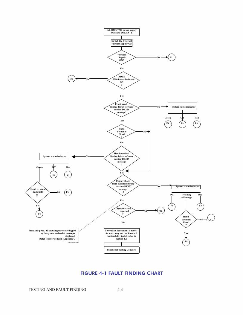
1-1 RUSKA 7710 GENERAL VIEW.........................................................................1-1 2-1 RUSKA 7710 ALTITUDE REFERENCE...............................................................2-2 2-2 RUSKA 7710 GENERAL VIEW.........................................................................2-3 3-1 SINGLE DISPLAY ...........................................................................................3-3 3-2 DUAL DISPLAY ..............................................................................................3-4 3-3 TRIPLE DISPLAY .............................................................................................3-4 3-4 RATE TIMER DISPLAY AERONAUTICAL UNITS .................................................3-5 3-5 RATE TIMER DISPLAY PRESSURE UNITS ...........................................................3-5 3-6 Pt ONLY DISPLAY..........................................................................................3-6 3-7 MAIN PRESSURE DISPLAY (LEAK MEASURE MODE) .........................................3-9 3-8 MAIN PRESSURE DISPLAY (CONTROL MODE) ................................................3-9 4-1 FAULT FINDING CHART ................................................................................4-4 5-1 ALTITUDE CORRECTION RACK MOUNTING................................................5-15 5-2 ARINC 565 OPERATING LIMITS ...................................................................5-21 E2-1 VACUUM METERING VALVE ..........................................................................6-8
LIST OF TABLES
4-1 FAULT FINDING............................................................................................4-4 6-1 MATERIALS LIST.............................................................................................6-3 6-2 ERROR MESSAGES ........................................................................................6-5 6-3 WARNING MESSAGES...................................................................................6-6 6-4 MAINTENANCE CHART.................................................................................6-9 -xi-

Abbreviations The following abbreviations are used in this manual; the abbreviations are the same in the singular and plural. abs Absolute AC Alternating current ADTS Air Data Test Set ALT Altitude ARINC 565 ARINC Standard Limits set ASI Airspeed indicator AUX Auxiliary CAS Calibrated airspeed CONFIG Configuration DC Direct current diff Differential DVM Digital voltmeter e.g. For example EOI End of input EPR Engine pressure ratio EEPROM Erasable electrically programmable read only memory etc. And so on ETP Execute test program EXT External Fig. Figure ft Feet FS Full-scale gnd Ground hm Hectometer hPa HectoPascal Hz Hertz IAS Indicated airspeed i.e. That is IEEE 488 Institute of Electrical & Electronic Engineers standard 488 data inHg Inches of mercury inHga Inches of mercury absolute inH2O Inches of water kg Kilogram km Kilometer km/h Kilometer per hour kts Knots lb. pound LED Light emitting diode m Meter or minute MW Megohm max Maximum mbar Millibar min Minute or minimum mm Millimeter mph Miles per hour
-xii-
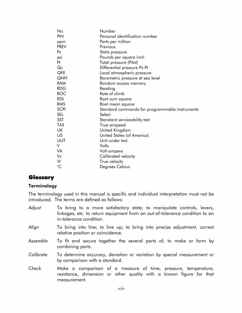
No. Number PIN Personal identification number ppm Parts per million PREV Previous Ps Statis pressure psi Pounds per square inch Pt Total pressure (Pitot) Qc Differential pressure Ps-Pt QFE Local atmospheric pressure QNH Barometric pressure at sea level RAM Random access memory RDG Reading ROC Rate of climb RSS Root sum square RMS Root mean square SCPI Standard commands for programmable instruments SEL Select SST Standard serviceability test TAS True airspeed UK United Kingdom US United States (of America) UUT Unit under test V Volts VA Volt ampere Vc Calibrated velocity Vt True velocity oC Degrees Celsius
Glossary Terminology
The terminology used in this manual is specific and individual interpretation must not be introduced. The terms are defined as follows:
Adjust To bring to a more satisfactory state; to manipulate controls, levers, linkages, etc. to return equipment from an out-of-tolerance condition to an in-tolerance condition.
Align To bring into line; to line up; to bring into precise adjustment, correct relative position or coincidence.
Assemble To fit and secure together the several parts of; to make or form by combining parts.
Calibrate To determine accuracy, deviation or variation by special measurement or by comparison with a standard.
Check Make a comparison of a measure of time, pressure, temperature, resistance, dimension or other quality with a known figure for that measurement.
-xiii-

Disconnect To detach the connection between; to separate keyed or matched equipment parts.
Dismantle To take apart to the level of the next smaller unit or down to all removable parts.
Examine To perform a critical visual observation or check for specific conditions; to test the condition of.
Fit Correctly attach one item to another.
Inspect Review the work carried out by Specialists to ensure it has been performed satisfactorily.
Install To perform operations necessary to properly fit an equipment unit into the next larger assembly or system.
Maintain To hold or keep in any particular state or condition, especially in a state of efficiency or validity.
Operate Ensure that an item or system functions correctly as far as possible without the use of test equipment or reference to measurement.
Readjust To adjust again; to move back to a specified condition; to bring back to an in-tolerance condition.
Reconnect To rejoin or refasten that which has been separated.
Refit Fit an item which has previously been removed.
Remove To perform operations necessary to take an equipment unit out of the next larger assembly or system. To take off or eliminate. To take or move away.
Repair To restore damaged, worn out or malfunctioning equipment to a serviceable, usable or operable conditions.
Replace Remove an item and fit a new or a serviced item.
Reset To put back into a desired position, adjustment or condition.
Service To perform such operations as cleaning, lubricating and replenishing to prepare for use.
Test Ascertain by using the appropriate test equipment that a component or system functions correctly.
-xiv-

SECTION 1.0 DESCRIPTION
1.1 INTRODUCTION o
o
o
o
o
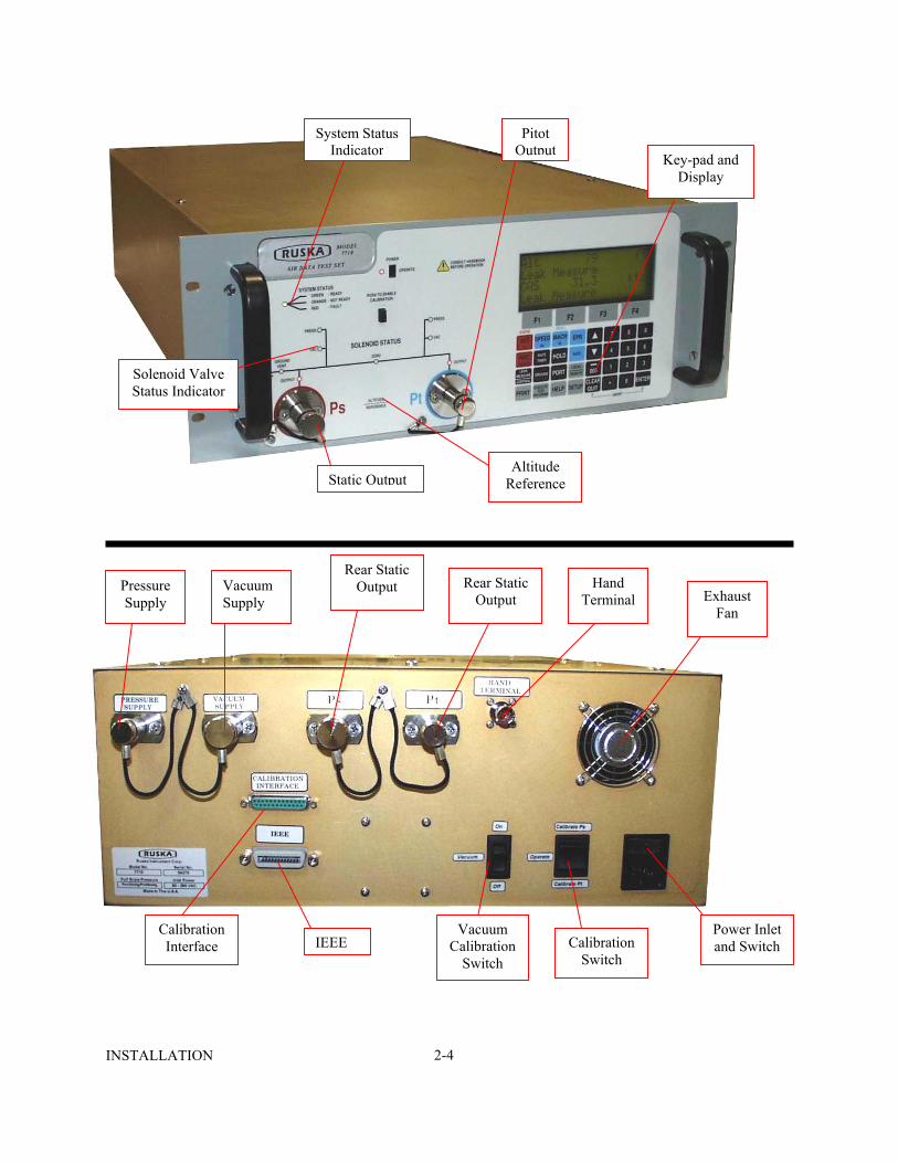
The 7710 ADTS is a bench top or rack-mounted system and, with external pressure and vacuum supplies connected, provides measurement and control for leak checks, calibration accuracy checks and functional tests of air data instruments, components and systems. The Ruska 7710 ADTS displays and operates in either units of pressure measurement or aeronautical units. In the control mode, the rate that the pressures change towards new set-points can be controlled in true aeronautical rate units. There are two independent pneumatic channels connected to the aircraft or instrument systems, one for static and one for pitot. They can be operated as measure only channels with leak testing facility or each can be control channels producing true pressure conditions for altitude and airspeed. To protect sensitive instruments and equipment a "ground" facility automatically and safely controls both channels to atmospheric pressure at the previously entered rates of change and then informs the operator when both channels are safely at "ground". The operator interface is the key pad and display on the front panel. The unit can also be controlled remotely using the IEEE 488 communications interface. The front panel contains the operate switch and a mimic panel with LED indicators showing the operation of the solenoid-operated pneumatic valves.
FIGURE 1-1 7710 ADTS GENERAL VIEW
DESCRIPTION 1-1

1.2 MEASUREMENT AND CONTROL RANGE SPECIFICATIONS
Display Functions and Units of Measure
When operating in either pressure measuring or pressure controlling modes, the 7710 ADTS can display the following information:
Aeronautical Functions Display Abbreviation Displayed Units (if applicable) Altitude ALT t, m Calibrated and True Airspeed CAS, TAS kts, km/h, mph Mach MACH Rate of Climb ROC ft/m, m/m, m/s, hm/m Rate of Airspeed Rt CAS kts/m, km/h/m, mph/m
Pressure Functions Display Abbreviation Display Units (if applicable) Static (Absolute) Ps [P] Pitot (ABsolute) Pt [P] Dynamic or Impact (Differential) Qc [P] Engine Pressure Ratio EPR - Rate of Ps Rt Ps [P]/m Rate of Pt Rt Pt [P]/m Rate of Qc Rt Qc [P]/m Rate of EPR Rt EPR EPR/m
Where [P] is the currently selected pressure units from the following list:
Mbar, inHg, mmHg, inH2O (4oC), inH2O (20oC), psi, hPa, kPa, inH2O (60oF)
Operating Range and Performance
The 7710 ADTS comes available in the Ps/Pt ranges of 32/32, 32/68, 32/100 and 100/100 inHg. The standard range is a 32 inHga Ps and a 100 inHga Pt, thereby producing a Qc range of 68 inHg. The following tables denote the performance of the 7710 with the Standard Range Sensor.
DESCRIPTION 1-2

Performance expressed in example aeronautical units
These values are based on the Standard Ps 32 and Pt 100 inHg Ranges.
Altitude Rate of Climb(ROC)
Calibrated Airspeed
(CAS)
Mach
Rate of Change
Of Airspeed Units Feet ft/min Knots - Kts/min
Maximum Range(1)
-3000 to 105,000
100,000
-100 to 1000
14.97
700
Calibrated or Standard Range(1)
0 to 80,000
9,000
-100 to 1000
5
700
Accuracy(2)
±2 at 0 ±3 at 30,000 ±9 at 60,000
±1% of value
±0.5 at 50 ±0.04 at 550 ±0.04 at 1000
Better than 0.002
±5% of value
Repeatability
±1 at 0 ±2 at 30,000 ±3 at 60,000
±0.5%
±0.2 at 50 ±0.01 at 550 ±0.01 at 1000
0.001 rising to
0.002
Resolution 1 1 0.01 0.001 0.1
Notes
(1) Altitude above 80,000 ft and the peak rates of climb are available but subject to the use of a suitable vacuum pump.
(2) The accuracy figures stated is defined as the combined effects of linearity, Hysteresis and repeatability throughout the operating temperature range of 10o to 35oC.
Performance expressed in example pressure units
Static (Ps)
Rate (Ps)
Pitot (Pt)
Differential(Qc)
Rate (Qc)
EPR
Units inHga InHg/min inHga InHg diff InHg/min InHg Maximum Range(1)
0 to 32
150
0 to 100
-30 to 68
150
0.1 to 10
Calibrated or Standard Range(1)
0 to 32
3
0 to 100
-30 to 68
3
0.1 to 10
Accuracy(1) 0.001 ±1% within 5 seconds
0.003 0.0032 ±1% within 5 seconds
Better than 0.005
Repeatability 0.0003 ±0.5% ±0.001 Resolution 0.0001 0.001 0.001 0.001 0.001 0.001
DESCRIPTION 1-3
(1) The accuracy figures stated is defined as the combined effects of linearity, Hysteresis and repeatability throughout the operating temperature range of 10o to 35oC.
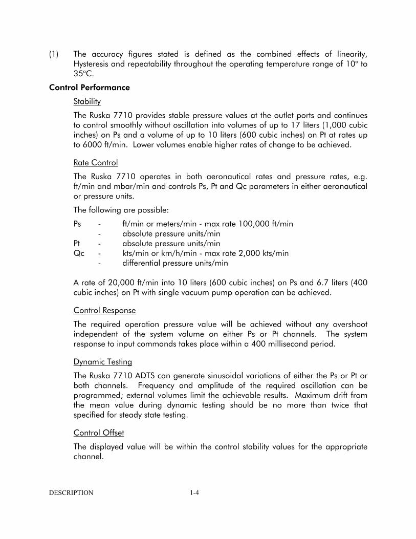
Control Performance
Stability
The Ruska 7710 provides stable pressure values at the outlet ports and continues to control smoothly without oscillation into volumes of up to 17 liters (1,000 cubic inches) on Ps and a volume of up to 10 liters (600 cubic inches) on Pt at rates up to 6000 ft/min. Lower volumes enable higher rates of change to be achieved.
Rate Control
The Ruska 7710 operates in both aeronautical rates and pressure rates, e.g. ft/min and mbar/min and controls Ps, Pt and Qc parameters in either aeronautical or pressure units.
The following are possible:
Ps - ft/min or meters/min - max rate 100,000 ft/min - absolute pressure units/min Pt - absolute pressure units/min Qc - kts/min or km/h/min - max rate 2,000 kts/min - differential pressure units/min A rate of 20,000 ft/min into 10 liters (600 cubic inches) on Ps and 6.7 liters (400
cubic inches) on Pt with single vacuum pump operation can be achieved.
Control Response
The required operation pressure value will be achieved without any overshoot independent of the system volume on either Ps or Pt channels. The system response to input commands takes place within a 400 millisecond period.
Dynamic Testing
The Ruska 7710 ADTS can generate sinusoidal variations of either the Ps or Pt or both channels. Frequency and amplitude of the required oscillation can be programmed; external volumes limit the achievable results. Maximum drift from the mean value during dynamic testing should be no more than twice that specified for steady state testing.
Control Offset
The displayed value will be within the control stability values for the appropriate channel.
DESCRIPTION 1-4

Physical Specification
Size ................................................ Standard 19" rack front panel 4U high (7") ................................................. Depth behind front panel 660.4 mm (26")
Weight......................................................................................................52 lbs ..............................................................................................w/o cabinet
Power .....................................................Single phase AC in the range 90-260 V ........................................................Over the frequency range 47-440 Hz ........................................................ No switching required - all automatic
Pressure Fittings Ps..................................................................................................... AN6 Pt ..................................................................................................... AN4 Pressure supply ................................................................................. AN4 Vacuum supply ................................................................................. AN6
DESCRIPTION 1-5

Pressure/Vacuum Requirements
The Ruska 7710 ADTS requires a single vacuum inlet and a single air pressure inlet. A leak tight system, controlled at the set-point, consumes only a small flow of air. The single vacuum source requires a pump capable of 120 liters/min (4.3 cubic ft/min) to achieve the rates detailed into the volumes listed, assuming no pneumatic leaking between Ps and Pt channels.
The air pressure source should be clean, dry air (or nitrogen) at a pressure of 3.5 to 6 bar (45 to 90 psi). The Ruska 7710 protects the controllers with an internal pressure regulator. Filtering should be better than 15 microns and a flow rate equivalent to 2.8 liters/min (0.1 cubic ft/min) at the above pressure.'
Warm-up
The Ruska 7710 requires a warm-up period of 2 to 3 hours to achieve the stated accuracy. Full accuracy and stability is achieved after the warm-up period. The message WARMUP will display in the lower right hand corner. When the message is no longer displayed, the 7710 performance will be within specifications. A removal of power will require a minimum 10 minute time frame for the message to reset.
Temperature
The ADTS has the following temperature ranges:
Operating.........................................................................+10o to +35oC
1.3 PACKAGING LIST
Ruska 7710
i) 7710 ADTS ii) Power supply cable
iii) Operator's Manual iv) Output fittings:
AN4 AN6
DESCRIPTION 1-6
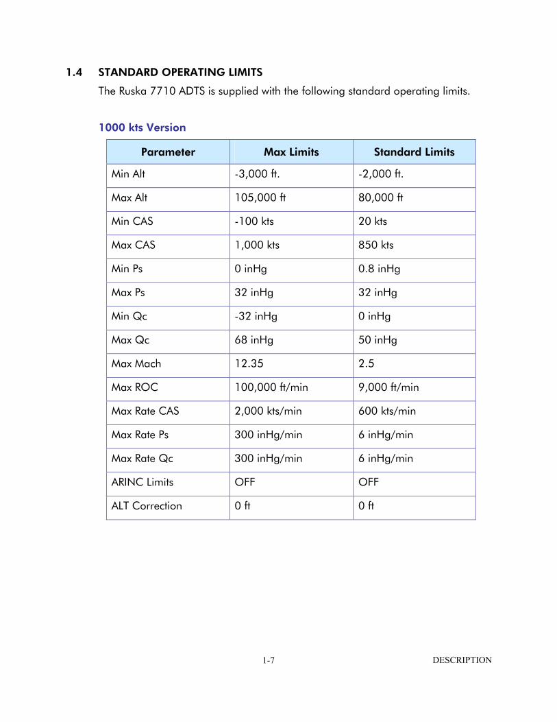
1.4 STANDARD OPERATING LIMITS
The Ruska 7710 ADTS is supplied with the following standard operating limits.
1000 kts Version
Parameter Max Limits Standard Limits
Min Alt -3,000 ft. -2,000 ft.
Max Alt 105,000 ft 80,000 ft
Min CAS -100 kts 20 kts
Max CAS 1,000 kts 850 kts
Min Ps 0 inHg 0.8 inHg
Max Ps 32 inHg 32 inHg
Min Qc -32 inHg 0 inHg
Max Qc 68 inHg 50 inHg
Max Mach 12.35 2.5
Max ROC 100,000 ft/min 9,000 ft/min
Max Rate CAS 2,000 kts/min 600 kts/min
Max Rate Ps 300 inHg/min 6 inHg/min
Max Rate Qc 300 inHg/min 6 inHg/min
ARINC Limits OFF OFF
ALT Correction 0 ft 0 ft
DESCRIPTION 1-7

THIS PAGE INTENTIONALLY LEFT BLANK
DESCRIPTION 1-8

SECTION 2.0 INSTALLATION
WARNING: VOLTAGES IN EXCESS OF 30 VOLTS (RMS) AC OR 50 VOLTS DC, IN CERTAIN CIRCUMSTANCES, CAN BE LETHAL. CARE MUST BE TAKEN WHEN WORKING ON LIVE, EXPOSED CONDUCTORS.
2.1 ELECTRICAL CONNECTION Power Supply Connection
The unit must be connected to the correct electrical power supply as stated, adjacent to the power connector.
CAUTIONS:
1. The supply must provide connection to a protective ground terminal. The unit must, at all times, be connected to the supply earth (ground).
2. The power supply cable and connector must be correctly rated for the power supply.
Note: The Ruska 7710 is normally supplied with an approved power supply cable for use in the country of delivery. This can limit the maximum supply voltage that can be safely used.
e.g. a NEMA 5-15P terminated cable, for use in the U.S.A., is approved for a maximum of 125V ac; it must be replaced for a higher supply voltage.
Pin European Color
U.S. Color
Function
1 Brown Black Live
4 Blue White Neutral
Center Green/Yellow Green Protective Earth (Ground)
o Make sure the power supply is off before connecting the power cable.
INSTALLATION 2-1

2.2 PNEUMATIC PRESSURE CONNECTIONS Ruska 7710 ADTS
Ps - AN6 Pt - AN4 o
o
o
o
Connect pressure and vacuum supplies to the rear panel PRESSURE and VACUUM connectors. The pressure supply should be clean, dry air or nitrogen. Please refer to the specification.
Connect the Unit Under Test (UUT) to either the front or rear Ps and Pt output connectors.
NOTE: Blanking caps must be fitted on unused front or rear outputs.
For single pipe testing of altimeters or similar, requiring only Ps, connect the UUT to Ps and fit the blanking cap on Pt.
For single pipe testing of airspeed indicators or similar, requiring only Pt, connect the UUT to Pt. The Ps output must be left open to atmosphere (no blanking cap) to provide a reference pressure.
NOTE: When single pipe testing airspeed indicators, to maintain the correct pressure differential above the true ground pressure the Pt ONLY mode of operation must be used.
INSTALLATION 2-2

2.3 POSITIONING OF THE RUSKA 7710 ADTS
o It is important that the position of the ADTS in relation of the components under test is known. An altitude correction must be made to allow for the difference in height between the reference level, indicated on the front panel, and the components under test. The Reference section contains details of altitude correction (SETUP, ALTITUDE). Components under test below the reference level of the ADTS would have a negative altitude correction. Above would be a positive correction.
rack-mounted ADTS
reference level
altitude correctioncomponents under test
reference level
FIGURE 2-1 7710 ADTS ALTITUDE REFERENCE
INSTALLATION 2-3
System S
Indicat
Solenoid Valve Status Indicator
Pressure Supply
Vacuum Supply
RearOu
Calibration Interface E
INSTALLATION
tatusor
Altitude Reference
Key-pad and
Display
Static OutputStatictput Rear Sta
Outpu
Vacuum Calibration
Switch
2-4
Pitot Output
tict
Hand Terminal Exhaust
Fan
Calibration Power Inletand Switch
IEESwitch

SECTION 3.0 OPERATION
3.1 PREPARATION
WARNING: Observe safety precautions stated in local orders and the aircraft or equipment servicing procedures.
o
o
o
o
o
o
o
o
o
o
Make sure the electrical and pneumatic connectors, electrical cables and pipes and positioning of the ADTS comply with the instructions and requirements in Section 2.0 Installation.
Carry out the following before use:
If necessary, carry out the maintenance task detailed in Appendix D.
Make sure the air data test set power supply switch on the front panel is set to OFF. Connect the air data test system to the electrical supply, make sure the supply includes a connection to a protective earth.
Inspect the pneumatic connections and piping for damage, ingress of dirt and moisture. Make sure the aircraft adaptors are serviceable.
Connect, to the air data test system, the piping necessary for the UUT test procedures to be carried out.
Connect the static and pitot hoses of the air data test set to the aircraft systems. Make sure blanking caps are fitted to an unused output connector.
3.2 POWER-UP Check the power indicator is illuminated and set the front panel power switch to OPERATE.
The display shows the following sequence:
a. Display power up screen. b. Ruska 7710 ADTS power up screen. c. [Date of the last calibration] self-test and initialization messages. d. User display showing Altitude or Altitude and Airspeed.
The 7710 ADTS always powers up in Leak Measure mode with the pressure controllers off. When changing to Control Mode the pressure supply and vacuum supply must be available and producing the correct pressure and vacuum.
NOTE: The display at power-up can be changed, see SETUP and CONFIGuration.
The equipment is now ready for use. Full accuracy and stability is achieved after the warm-up period. The display shows "WARMUP" in the lower right hand corner during the warm-up period. (For explanation see Section 1.2). For a typical sequence of operation refer to Section 3.10.
OPERATION 3-1

3.3 AIRCRAFT SYSTEM PROTECTION o
o
o
˙ ˙ ˙
˙ ˙
o
o
o
The 7710 protects the UUT against user error and leaks in the system.
NOTE: The pressure and vacuum supplies must be available.
The system protection operates:
a. Limit checking of user entered set-points. b. Automatic regain of control if leak rate is over limit during leak testing. c. Automatic regain of control if a leak takes the system pressure outside of limits.
3.4 LIMIT CHECKING All data entered is checked against minimum and maximum limits set for the particular limit set in use. If these limits are exceeded, the data entry is ignored and a warning message displayed showing the minimum and maximum values that can be entered. The system also checks all limits of associated parameters. If these limits are exceeded when a new value is entered, the display shows the name of the associated parameter. e.g., If a Mach limit is exceeded when entering an airspeed value the display shows "Mach" and the equivalent maximum and minimum limit as airspeed values. Similarly, if an ARINC 565 limit is exceeded when entering a value and, ARINC limits are enabled, the display shows "ARINC". Using the SETUP function, previously stored sets of limits can be recalled for use. Each set of limits is stored under an aircraft name including "Standard" limits supplied with the 7710 ADTS.
To select the limits in use: Press SETUP. Select [LIMITS]. Use [NEXT] or [PREV] to select the limits required. Each set of limits is identified by its name. The ADTS, at manufacture, contains three predefined sets of limits called "STANDARD", "MAX" and "CIVIL". Select [SAVE] to select the limits. Press QUIT to return to the pressure display
Using the CONFIGuration function, new sets of limits can be created and existing sets of limits can be edited. In addition, the set of limits in use at power-up can be selected. If required, this selection can be locked to prevent unauthorized changing of the limits. The pressure controllers within the ADTS have the ability to feed a leak within an aircraft system. When first testing an aircraft system, a leak test must be carried out at low altitude and airspeed. If, during a leak test, a leak in the system produces a rate of climb greater than ±3000 ft/min or a rate of change of airspeed greater than ±300 knots/min, then the pressure controllers automatically regain control to minimize damage to the aircraft system. This AUTO LEAK RECOVERY facility can be disabled.
OPERATION 3-2

o
o
o
o
o
o
If a leak causes the system pressures to exceed any limit during a leak test, the pressure controllers automatically regain control. This AUTO LIMIT RECOVERY system can be disabled. If negative airspeed (or Qc) occurs in measure mode, the zero value is automatically opened for one second to balance the airspeed. This only applies when the minimum CAS (or Qc) limit is zero. Limits cannot be changed with SETUP switched off or Limit Lock enabled.
3.5 DISPLAYS (Fig 3.1, Fig 3.2 and Fig 3.3) The display normally shows pressures and rates or aeronautical equivalents. It can be set-up to concurrently show one parameter (single), two parameters (dual) or three parameters (triple). The ADTS automatically reverts to the pressure display if left inactive in any set-up or menu type display for a period of more than one minute. The triple display always shows altitude and airspeed; with pressure units selected, the display always shows Ps and either Qc, Pt or EPR. When ALT or CAS are selected the display shows the aim and measured values of ALT and CAS as a dual display. With any other selected parameter the display shows the measured values of ALT and CAS and, the aim and measured value of the other selected parameter. Additional display modes are available for options.
Measured value Controlled T for timed rate Units of or measured of change measurement parameter
Aim (set-
or "leak- controller
ALT 10000 ft Aim 10000 < | |
point or target) Pointer for Special measure" when parameter messages selected off
FIGURE 3-1 SINGLE DISPLAY
OPERATION 3-3

Measured values T for timed rate of change
Controlled or measured Units of parameters measurement
Aim (set-point or target) Pointer for primary Special
ALT 10000 ft Aim 10000 < CAS 582 kts Aim 600 |______|
or Leak Measure when parameter - aim that message controller selected off changes on data entry
FIGURE 3-2 DUAL DISPLAY Measured values T for timed rate of change Constant indication Units of of values measurement Current changing parameter Aim (set-point or target) Pointer for primary Special
ALT 10000 ft CAS 582 kts ROC 2995 ft/m Aim 3000 < |______|
or Leak Measure when parameter - aim that messages controller selected off changes on data entry
FIGURE 3-3 TRIPLE DISPLAY
3.6 RATE TIMER DISPLAYS (Fig 3.4 and Fig 3.5) The rate timer displays are generated after completion of the rate timing and
when the system is in a "Leak measure" mode. These displays do not depend on the display mode (single, dual, triple or option). Pressing a parameter key (ALT, ROC, etc.,) or QUIT exits the rate timer displays.
OPERATION 3-4

Parameters T for timed rate Measured Timed value of change Special Units of Messages measurement
FIGURE 3-4 RATE TIMER DISPLAY AERONAUTICAL UNITS T for timed rate Parameters Measured Timed value of change Units of measurement Special
ROC 2 T ft/m Aim 6 T kts/m Timed Rates |__________|
NOTE: Thererate time
3.7 Pt ONLY The Pt on
measured
Rt Ps 0.08 T mbar/mRt Pt 0.02 T mbar/mRt Qc 0.06 T mbar/m Timed Rates |__________|
message
FIGURE 3-5 RATE TIMER DISPLAY PRESSURE UNITS
is no pointer for the primary parameter, values cannot be entered in the r displays.
DISPLAY (Fig 3.6) ly display overrides the other display modes (single, dual and triple). The altitude and the CAS are produced from Ps in measure mode.
OPERATION 3-5

Altitude is Measured T for timed rate always shown altitude of change Selected parameter Units of measurement Aim (set-point or target) Pointer for Special or "leak-measure" if parameter messages Pitot controller selected off
FIGURE 3-6 Pt ONLY DISPLAY
3.8 CHANGING THE DISPLAY o
o ˙ ˙ ˙ ˙ ˙ ˙ ˙ ˙
o
The display may be set-up to show either one (single), two (dual) or three (triple) parameters concurrently.
To change the display: Press SETUP. Select [MORE]. Select [DISPLAYS/OPTIONS]. Select [DISPLAY TYPE]. Using [NEXT] or [PREV]. Select either SINGLE, DUAL or TRIPLE. Press [SAVE] to accept. Press QUIT repeatedly to return to user display.
NOTE: If options are fitted other display types may be available. Display cannot be changed with SETUP switched off or in minimum mode.
ALT 407 ft Pt Only CAS 0.0 kts Aim 0.0 < |__________|
3.9 CONTROL OR MEASURE PARAMETER To change the displayed parameter: Value parameters - Press the parameter key e.g., press SPEED to display airspeed.
Rate parameter - Press the associated parameter key followed by the rate key for that channel. e.g., display airspeed rate, press SPEED then RATE. ROC may be directly pressed without first pressing ALT.
OPERATION 3-6
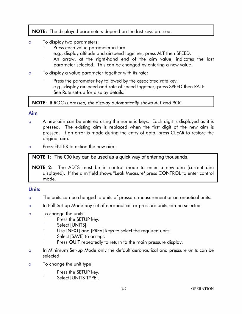
NOTE: The displayed parameters depend on the last keys pressed.
o ˙
˙
o
˙
o
o
o
o
o ˙ ˙ ˙ ˙ ˙
o
o
˙ ˙
To display two parameters: Press each value parameter in turn. e.g., display altitude and airspeed together, press ALT then SPEED. An arrow, at the right-hand end of the aim value, indicates the last parameter selected. This can be changed by entering a new value.
To display a value parameter together with its rate:
Press the parameter key followed by the associated rate key. e.g., display airspeed and rate of speed together, press SPEED then RATE. See Rate set-up for display details.
NOTE: If ROC is pressed, the display automatically shows ALT and ROC.
Aim
A new aim can be entered using the numeric keys. Each digit is displayed as it is pressed. The existing aim is replaced when the first digit of the new aim is pressed. If an error is made during the entry of data, press CLEAR to restore the original aim.
Press ENTER to action the new aim.
NOTE 1: The 000 key can be used as a quick way of entering thousands.
NOTE 2: The ADTS must be in control mode to enter a new aim (current aim displayed). If the aim field shows "Leak Measure" press CONTROL to enter control mode.
Units
The units can be changed to units of pressure measurement or aeronautical units.
In Full Set-up Mode any set of aeronautical or pressure units can be selected.
To change the units: Press the SETUP key. Select [UNITS]. Use [NEXT] and [PREV] keys to select the required units. Select [SAVE] to accept. Press QUIT repeatedly to return to the main pressure display.
In Minimum Set-up Mode only the default aeronautical and pressure units can be selected.
To change the unit type:
Press the SETUP key. Select [UNITS TYPE].
OPERATION 3-7

˙ ˙ ˙
o
o
o
o
o
o
o
o
o
o
o ˙
Select either [AERO] or [PRESS] to select the unit type. Select [SAVE] to accept. Press QUIT repeatedly to return to the main pressure display.
NOTE: The default pressure and aeronautical units are defined in the CONFIGuration mode.
If Set-up Mode is switched off, units cannot be changed.
Help System
The help information includes further details of the function and details associated functions, see the Reference section for details.
SETUP and CONFIGuration
The SETUP key provides access to secondary functions using a menu system, extends the keyboard and allows many of the ADTS functions to be customized. All changes made under SETUP are temporary and will be lost when the system is switched off. The range of options allowed in set-up is determined by the set-up mode.
Holding down the F1 key while pressing SETUP provides access to the CONFIGuration mode. CONFIG is similar to SETUP with many identical functions. The changes made under CONFIG are permanent and remain set after the system is switched off. CONFIG can be used to change the power-up default settings of the ADTS functions.
3.10 TYPICAL SEQUENCES OF OPERATION The following example is a typical operating sequence. For further information on the functions used, refer to the Reference section.
All key presses are shown in CAPITAL letters.
Key presses inside brackets e.g., [MORE], are soft key presses (i.e., function key selections indicated from the screen.
Controlling to Set-point
With the unit warmed up and temperature stabilized, connect the pitot and static hoses. Temporarily seal the free ends of the hoses.
Set the units to feet and knots.
Set the display to dual display.
Using the SETUP menu, choose the limits set for the aircraft or UUT. Press SETUP, [LIMITS], and [NEXT] repeatedly to select the limit set from those available.
OPERATION 3-8

˙
o
o
o
o
o
o
o
o
o
Press [SEL] to save and then press QUIT repeatedly until the main pressure screen shown below is displayed.
NOTE: The numeric value of the parameters displayed change with each power-up sequence. The amount of change depends on local atmospheric pressure conditions at the time of power-up. Fig. 3.7 is an example of the display at power-up. See section 1.2 concerning the WARMUP message.
ALT 125 ft Leak Measure CAS 0.0 kts Leak Measure WARMUP
FIGURE 3-7 MAIN PRESSURE DISPLAY (LEAK MEASURE MODE) Press the CONTROL key to turn on the pressure controllers.
To apply an altitude of 5000 ft at a rate of climb of 6000 ft/min and an airspeed of 300 kts at a rate of 600 kts/min press the following keys:
SPEED then RATE to select rate of change of speed.
6, 0, 0, ENTER to set the rate.
SPEED to select Airspeed.
3, 0, 0, ENTER to set an airspeed of 300 kts. (Airspeed (CAS) now starts increasing).
ROC to select Rate of Climb.
6, 0, 0, 0, ENTER to set the ROC
ALT to select the Altitude.
5, 0, 0, 0, ENTER to set Altitude. (The altitude [ALT] now starts increasing).
SPEED to view Altitude and Speed simultaneously.
OPERATION 3-9

ALT 4050 ft Aim 5000 CAS 289.0 kts Aim 300.0 <
FIGURE 3-8 MAIN PRESSURE DISPLAY (CONTROL MODE)
NOTE: When ALT and SPEED are changing at the same time, and automatic airspeed rate is enabled, the system automatically adjusts the airspeed rate so that the aim points are reached at the same time. The airspeed rate will not exceed the entered aim value.
˙
˙
˙ ˙
˙ ˙ ˙ ˙ ˙
o
o
Wait for the aim values to be achieved.
Observe over a period of 1 minute that the value of ALT stays within ±10 ft and the value of CAS with ±1 kt.
Leak Testing the ADTS
NOTE: Compressing a gas generates heat. Gas heated or cooled in an enclosed volume causes a pressure change. It is important, especially for leak testing, to allow enough time for the heated gas to cool and the pressure to stabilize.
Press CONTROL to return to "Leak Measure" mode. Press RATE TIMER, F3 - Wait 5 minutes, Time 1 minute.
NOTE: Different wait and time periods can be selected by pressing F1 or F2.
Wait until rate timer has completed and results are displayed. Check ROC is less than ±100 ft/min and RATE CAS is less than ±1 kt. Press CONTROL to return to "Control" mode. Press GROUND, [Go to Ground]. Wait until the display shows SAFE AT GROUND.
After a successful leak test, the ADTS is now ready to be connected to an aircraft system or unit under test.
After an unsuccessful first time leak test leave the system to achieve thermal stability for a further five minutes, press QUIT and repeat the leak test. If the leak test is successful, the ADTS is now ready to be connected to an aircraft system or unit under test.
OPERATION 3-10

o
o
o
o
o
˙ ˙ ˙
o
o
o
o
o
o
o
After another unsuccessful leak test, disconnect both hoses, check the condition of the o-rings on the Ps and Pt connectors as detailed in the maintenance section and firmly replace the blanking caps. Please QUIT and repeat the leak test procedure.
After a successful leak test without hoses connected, replace or repair the faulty hose(s) and retest. If the ADTS fails the leak test without hoses connected, switch off and return the unit to the Ruska repair center.
Testing Aircraft Systems or UUT
WARNING: Observe the appropriate safety instructions and procedures detailed in the aircraft maintenance manuals or component maintenance manuals.
Connect the hoses and appropriate adaptors to the aircraft system or UUT.
To make sure that the connections to the aircraft system or UUT are not leaking carry out a leak test detailed in the appropriate aircraft or component manual.
Go To Ground and Shut-down
On completion of testing and, before disconnecting from the aircraft system or UUT, the pressures in the system must be taken to the local atmospheric pressure (ground) with zero airspeed.
If the display shows "Leak Measure", press CONTROL. Press GROUND, [GO TO GROUND]. Wait for the display to show SAFE AT GROUND. It is now safe to disconnect the aircraft system or UUT.
The pressure in the system changes towards ground. The ground pressure or "GROUND" replaces the static or altitude aim value.
If required, new rates of change can be entered while going to ground.
To change the ROC or static rate, press ROC and enter the new value.
To change the airspeed or Qc rate, press SPEED then RATE and enter the new value.
To change from going to ground, enter a new altitude (static) or airspeed (Qc) set-point.
When the airspeed is zero and the Ps channel pressure is close to ground, the atmospheric pressure is re-measured to update the recorded ground pressure (QFE). During this period, the display shows the message CHECKING GROUND. The ADTS then reconnects to the aircraft system and equalizes the pressures. Commands cannot be entered when these two messages are displayed.
The Ps pressure is then taken to the new recorded atmospheric pressure and, at this new pressure, the display shows the message "SAFE AT GROUND". The ground and zero valves remain open so that the aircraft system is permanently vented to atmosphere.
OPERATION 3-11

o
o
˙ ˙ ˙ ˙ ˙
o
o ˙ ˙ ˙ ˙ ˙
o
˙ ˙ ˙ ˙ ˙
o
o
Press QUIT to continue with normal operation. The ground and zero valves automatically close.
3.11 OTHER FEATURES Mach Test and Constant Mach
To go to 0.8 Mach, enter Control Mode and proceed as follows:
Press SPEED then RATE to select rate of change of airspeed. Enter required rate, e.g. 300 kts/min. Press MACH. Enter 0.8. Wait for the Mach to be achieved.
NOTE: If the altitude changes the system automatically adjusts the airspeed to keep the Mach value constant.
True Airspeed
The normal airspeed parameter is Calibrated Airspeed (CAS) (equivalent to IAS for testing purposes).
The airspeed parameter may be changed to True Airspeed (TAS) as follows: Press SETUP then SPEED. Select [CAS/TAS]. Select [TAS]. Press QUIT repeatedly to exit set-up. Press SPEED.
The display now shows the airspeed parameter as TAS.
NOTE: Airspeed parameter type can only be changed in Full Set-up mode. Rate of change of airspeed will still be shown as Rate CAS.
Pitot temperature (qt) is used in the calculation of TAS. To enter qt: Press SETUP. Press SPEED. Select [Pt TEMPERATURE]. Enter the temperature measured by the aircraft's Pitot temperature sensor. Press QUIT three times to return to user display.
NOTE: Pitot temperature can only be changed in Full Set-up mode.
Engine Pressure Ratio (EPR)
The ADTS may be used to check EPR sensors and indicators. Use Ps for INLET pressure and Pt for OUTLET pressure
To carry out an EPR check, the display must be showing pressure units e.g., mbar or inHg.
OPERATION 3-12

o ˙ ˙ ˙ ˙
o
˙ ˙ ˙ ˙
o
˙
˙ ˙ ˙ ˙ ˙ ˙ ˙ ˙ ˙
To change units in FULL SETUP Mode: Press SETUP. Select [UNITS]. Select required pressure units for display using [NEXT], [PREV] and [SAVE]. Use QUIT to return to pressure display.
To change units in MINIMUM SETUP Mode:
Press SETUP. Select [UNITS TYPE]. Select [PRESS]. Use QUIT to return to the main pressure display
Pressure units cannot be selected when set-up mode is switched off
To enter an EPR of 1.8 with inlet pressure of 500 mbar (or 15 inHg), proceed as follows:
If the display shows "Leak Measure", press CONTROL to regain control.
NOTE: The pressure/vacuum pumps must be switched on.
Press Ps RATE to select rate of change of static. Enter required rate of change e.g., 1000 mbar/min, (30 inHg/min). Press EPR then RATE to select EPR rate. Enter required value e.g., 5 EPR/min and press ENTER. Press Ps. Enter 500 (or 15 if using inHg) and press ENTER. Press EPR. Enter 1.8 and press ENTER. An EPR of 1.8 will quickly be achieved.
NOTE: EPR testing can also be performed by specifying the INLET and OUTLET pressures. Using Ps for the INLET pressure and Pt for the OUTLET pressure.
3.12 QUICK REFERENCE The following charts provide a user reference for the normal operation, set-up and configuration functions of the ADTS. In the KEY column the following apply:
ALT - Key. [NEXT] - Item in menu (soft key). (SINGLE DOUBLE) - Sequence of parameters selected by NEXT key. (craft1 craft2...) - Sequence of names selected by NEXT key. data entry - Enter number from key-pad.
The following chart starts with the display showing the main pressure display (Leak Measure mode or Control mode).
OPERATION 3-13

KEY-PAD FUNCTION
Key/selection Function and comments F1-F4 Function keys for menus
ALT Ps Altitude (Aeronautical units) or Ps (Pressure units) SPEED Qc Airspeed (Aeronautical units) or Qc (Pressure units) MACH Pt Mach (Aeronautical units) or Pt (Pressure units) EPR Engine Pressure Ratio (pressure units only) ROC Ps RATE Rate of Climb (Aeronautical units) or Rate of Ps (Pressure units) RATE TIMER Start timing rate of change F1 Wait and time choice 1 F2 Wait and time choice 2 F3 Wait and time choice 3 HOLD Hold pressure at present value - Press again to release RATE Rate of change of Pitot parameter - Press Pitot parameter then RATE LEAK MEASURE/CONTROL Switches (toggles) between measure mode (for leak testing) and control mode Takes Ps to atmospheric pressure and Qc to zero at normal rates of change GROUND currently in use [GO TO GROUND] Display local atmospheric (ground) pressure [DISPLAY QFE] Display sea level equivalent of local atmospheric pressure [DISPLAY QNH] See option User Manual PORT Switches (toggles) between remote and local operation REMOTE Prints current parameter values Inserts alphabet character in user text PRINT Deletes last character of user text [ALPHA] Numeric entry for user text [BACK] See Option manual data entry Press HELP then other key for further information EXECUTE TEST PROGRAM Temporary set-up - lost at power down HELP QUICK REFERENCE - MINIMUM SETUP SETUP Configuration - changes power-up defaults See QUICK REFERENCE - SETUP Hold F1 while pressing SETUP - then enter PIN or SETUP + F1 Increments aim See QUICK REFERENCE - CONFIG Decrements aim Number entry NUDGE UP (↑) Minus sign for first number entry 000 (thousand) if not first number of NUDGE DOWN (↓) entry 0-9 Clear number entry - quit from menu or clear warning message -000 Complete number entry CLEAR QUIT ABORT - restart with power-up ENTER CLEAR + ENTER
OPERATION 3-14

FULL SET-UP Key/selection Function and comments SETUP [UNITS] Select units [NEXT] Step through available units [PREV] Step back through available units [SAVE] Select displayed units [LIMITS] Select set of limits [NEXT] (aircraft 1/aircraft2...) [PREV] As NEXT, in reverse order [SEL] Select displayed limit set [OSC] Oscillate about aim [Ps] [START] [STOP] [FREEZE] [AMPL/FREQ] [AMPL] data entry As for Ps channel [FREQ] data entry Dual channel or Pt only control [Pt] [MORE] [DUAL CH./Pt ONLY] [ON] [OFF] [DISPLAYS/OPTIONS] [DISPLAY TYPE] Select single, dual or triple display [NEXT] (SINGLE\DUAL\TRIPLE\ENCODER) [PREV] As NEXT, reverse order [SAVE] Save displayed Display Type [ZERO SENSOR] [STRT] [VAC] [DRY] [STRT] [ABRT] [OPTIONS] See option manual [CLOSE O/P VALVES] Close output valves [OPEN O/P VALVES] Open output valves [SYSTEM SELF TEST] Start self test ALT Altitude correction value data entry Auto zero function SPEED [AUTO ZERO] [ON] Calibrated or true airspeed [OFF] [CAS/TAS] Temperature for true airspeed [CAS] Enter Pitot temperature [TAS] [Pt TEMPERATURE] Mach limit data entry Defined by current limits OPERATION 3-15

FULL SET-UP Key/selection Function and comments SETUP contd. MACH Removes Mach limit [DEFAULT] Enables Mach limit [OFF] Enter new Mach limit [ON] data entry
RATE TIME Set-up WAIT and TIME time periods [WAIT/TIME ON F1] For F1 [TIME] Change to TIME [WAIT] Change to WAIT data entry of TIME time data entry of WAIT time [WAIT TIME F2] See [Wait/Time on F1] [WAIT TIME F3] See [Wait/Time on F1] RATE Automatic airspeed rate [ON] Automatic [OFF] Manual LEAK MEASURE [AUTO LEAK] Auto leak recovery on or off [ON] [OFF] [AUTO LIMIT] Auto limit recovery on or off [ON] [OFF] GROUND Airfield altitude for QNH display data entry PORT See option user manual REMOTE Remote mode lock [ON] [OFF] PRINT [DATE/TIME] Adjust date and time [DATE] data entry Enter Date [TIME] data entry Enter Time HELP Help on SETUP NUDGE UP (↑) Enter nudge values [NEXT] (ALT\CAS\TAS\MACH\TOC\RATE\RATE CAS) Aeronautical units or data entry (Ps\Pt\Qc\EPR\RATE Ps\RATE Qc\RATE EPR) Pressure units [PREV] As NEXT, in reverse order data entry Required nudge increment NUDGE DOWN (↓) As NUDGE UP
OPERATION 3-16
MINIMUM SET-UP Key/selection Function and comments
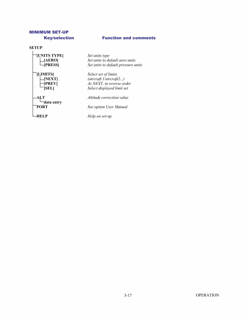
SETUP [UNITS TYPE] Set units type [AERO] Set units to default aero units [PRESS] Set units to default pressure units [LIMITS] Select set of limits [NEXT] (aircraft 1/aircraft2...) [PREV] As NEXT, in reverse order [SEL] Select displayed limit set ALT Altitude correction value data entry PORT See option User Manual HELP Help on set-up OPERATION 3-17

CONFIGURATION Key/selection Function and comments SETUP + F1 Hold F1 and press SETUP to enter CONFIG [UNITS] Default units [AERONAUTICAL] Select default aeronautical units [NEXT] Step through available units [PREV] Step back through available units [SAVE] Save selected units [PRESSURE] Select default pressure units [NEXT] Step through available units [PREV] Step back through available units [SAVE] Save selected units [TEMPERATURE] Select default temperature units [C] oC [F] oF [LIMITS] Configure sets of limits [EDIT LIMITS] Change limit values [EDIT EXISTING] Change existing values [NEXT] (aircraft 1\aircarft 2...) [PREV] As NEXT, in reverse order [SEL] Select aircraft to EDIT limits [NEXT] NAME\MAX ALT\MIN ALT\MAX CAS\MIN CAS\MAX MACH\MAX ROC \MAX RATE CAS\MIN Ps\MAX Ps\MIN Qc\MAX Qc\MAX RATE Ps\ MAX RATE Qc\ARINC LIMITS\ALTITUDE CORRECTION [PREV] As NEXT in reverse order [ON/OFF] Switch (toggle) to ARINC 565 limits data entry Limit value [ALPHA] Insert alphabet character in name ( ) Nudge UP select next letter in alphabet ( ) Nudge DOWN select previous letter in alphabet [BACK] Delete last character in name [MAX LIMITS] Create maximum limits called "MAX" [EDIT NEW] Create new limits As for [EDIT EXISTING][SEL] above [CLEAR LIMITS] Clear an existing set of limits [NEXT] (aircraft 1\aircraft 2...) [PREV] As NEXT, in reverse order [SEL] Clear selected limits [YES] Confirm delete [NO] [LOCK AIRCRAFT] Only DEFAULT limits available in USER mode [ON] SETUP can be sued to select aircraft [OFF] [DEFAULT AIRCRAFT] [NEXT] (aircraft 1\aircraft 2...) [PREV] As NEXT, in reverse order [SEL] Select aircraft limits used at power-up. May be locked. SETUP + F1 contd.
OPERATION 3-18

Key/selection Function and comments SETUP + F1 contd. [MORE] [DUAL CH/PtONLY] Normal or Pt only control [Pt ONLY] For single pipe testing of airspeed and Mach indicators [DUAL CHANNEL] Normal testing [DISPLAY/OPTIONS] [DISPLAY TYPE] Configure display type [NEXT] (SINGLE\DUAL\TRIPLE\ENCODER) [PREV] As NEXT, in reverse order [SAVE] Save selection [OPTIONS] See option manual user [DATE FORMAT] Format of date text [DMY] UK format DD/MM/YY [MDY] US format MM/DD/YY [SETUP MODE] Limits access to set-up functions [OFF] [MIN] [FULL] SPEED Auto zero function [AUTO ZERO] [ON] [OFF] Configure Calibrated to True airspeed [CAS/TAS] [CAS] [TAS] Configure Pt temperature [Pt TEMPERATURE] data entry Configure WAIT and TIME times RATE TIME For F1 [WAIT/TIME ON F1] Change to TIME [TIME] Change to WAIT [WAIT] TIME time period data entry WAIT time period data entry See [Wait/Time on F1] [WAIT/TIME ON F2] See [Wait/Time on F1] [WAIT/TIME ON F3] Automatic airspeed rate RATE Automatic [ON] Manual [OFF] LEAK MEASURE Auto leak recovery Lock [AUTO LEAK ON/OFF] [ON] [OFF] Lock auto leak recovery Lock [AUTO LEAK LOCK] [ON] [OFF] Auto limit recovery state [AUTO LIMIT ON/OFF] [ON] [OFF] Lock auto limit recovery state [AUTO LIMIT LOCK] [ON] [OFF] SETUP + F1 contd.
OPERATION 3-19
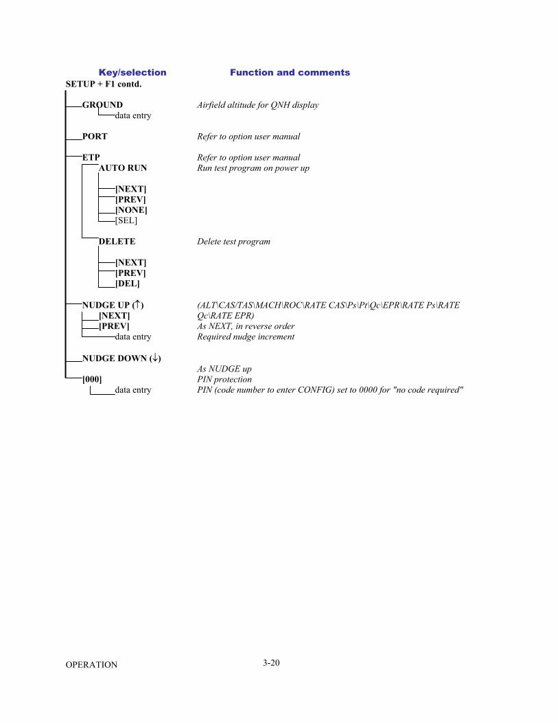
Key/selection Function and comments SETUP + F1 contd. GROUND Airfield altitude for QNH display data entry PORT Refer to option user manual ETP Refer to option user manual AUTO RUN Run test program on power up [NEXT] [PREV] [NONE] [SEL] DELETE Delete test program [NEXT] [PREV] [DEL] NUDGE UP (↑) (ALT\CAS/TAS\MACH\ROC\RATE CAS\Ps\Pt\Qc\EPR\RATE Ps\RATE [NEXT] Qc\RATE EPR) [PREV] As NEXT, in reverse order data entry Required nudge increment NUDGE DOWN (↓) As NUDGE up [000] PIN protection data entry PIN (code number to enter CONFIG) set to 0000 for "no code required"
OPERATION 3-20
3.13 ROUTINE MAINTENANCE
WARNING: Switch off and disconnect the power supply before starting any maintenance task.
Carrying out the maintenance tasks detailed in Appendix D.
3.14 SERVICING PROCEDURES
The following procedures provide instructions to test and replace items for the operator. Return the unit to Ruska Instrument Corporation Service Department for further testing and replacement of items.
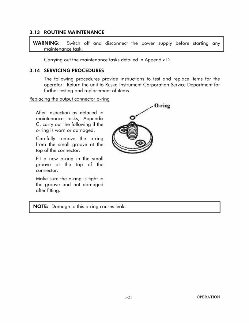
Replacing the output connector o-ring
N
After inspection as detailed inmaintenance tasks, AppendixC, carry out the following if theo-ring is worn or damaged:
Carefully remove the o-ringfrom the small groove at thetop of the connector.
Fit a new o-ring in the smallgroove at the top of theconnector.
Make sure the o-ring is tight inthe groove and not damagedafter fitting.
OTE: Damage to this o-ring causes leaks.
OPERATION 3-21

Cable Tests
Carry out the following check when detailed in Testing and Fault Finding, Section 4.
Measure continuity using the DVM set to an appropriate range
Measure the continuity between corresponding pins at each end of each cable assembly. The measured resistance must not exceed 0.10Ω.
Measure insulation using the DVM set to an appropriate range.
Measure the insulation resistance between the shell of the connector and all individual pins in turn.
Measure the insulation resistance between the shell of the appropriate connectors and all pins in turn.
Measure also the resistance between individual pairs of pins (i.e., 1-2, 1-3, 1-4, 1-5, 1-6, 2-3, 2-4, 2-5, 2-6, 3-4, 3-5, 3-6, 4-5, 4-6 and 5-6). In all cases the resistance must exceed 10 MΩ.
OPERATION 3-22
SECTION 4.0 TESTING AND FAULT FINDING
4.1 INTRODUCTION o
o
o
o
o ˙
˙ ˙
The ADTS contains a built-in, self-test and diagnostic system. The system continuously monitors the performance of the unit and at power-up carries out a self-test. Warning and error messages are displayed during normal operation if out of range values are entered or if faults occur.
This section details the standard serviceability test. Possible error messages and codes that can be displayed are found in Appendix C. A fault diagnosis flow chart and table provide the probable cause and procedures to rectify specific symptoms. A list of the maintenance/repair tasks is contained in Appendix D.
Error messages When the display shows a message indicating entry of incorrect data or values, pressing QUIT clears the message and allows the correct entry to be made.
4.2 STANDARD SERVICEABILITY TEST The following procedure can be used to check the functions and facilities of the ADTS. When a key on the front panel keypad or the optional hand terminal key-pad is referred to, the term PRESS is used, e.g., Press ALT. When a menu item on the display is referred to, the term SELECT is used. In the text, the menu item is enclosed in square brackets, e.g., Select [MORE]. Menu items are selected using the appropriate function or 'soft' keys F1, F2, F3 and F4. The menu items may be shown either over the function keys or as a list on the display.
Procedure
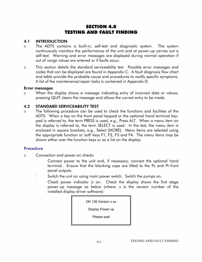
Connection and power-on checks Connect power to the unit and, if necessary, connect the optional hand terminal. Ensure that the blanking caps are fitted to the Ps and Pt front panel outputs. Switch the unit on using main power switch. Switch the pumps on. Check power indicator is on. Check the display shows the first stage power-up message as below (where: x is the version number of the installed display driver software):
DK 126 Version x.xx
Display Power up
Please wait
TESTING AND FAULT FINDING 4-1

˙
˙
˙ ˙ ˙ ˙
˙
˙
˙ ˙
˙ ˙ ˙
Check the second stage power-up message displays as below (where: x is the version number of the installed main operating software (which should be in the range 4.32 to 4.39):
NOTE: The software version may also
The ADTS displays any detcontinues through the follo
7
V
Calibration date. Self-test. Measuring ground pEqualizing system p
Check that the display thenairspeed (CAS to TAS) valu
1 The displayed values change a
2 The display shows the "WARMthat full pressure accuracy anmessage clears after a minimdepending on the length of timSection 1.2. This indication proceed without waiting for th
3 An automatic zero (if enabledand the state of the valves, oseconds. Commands may stil
Press the MACH key and Mach measured values. Switch on the vacuum pumPress CONTROL to go to cpressing 5, 0, 0, 0, ENTEREnter rate or use default raEnter an airspeed aim of 5Check that these aim value
TESTING AND FAULT FINDING
Ruska
710 ADTS
DK 127
ER 4.3x
be supplemented by extra alpha characters.
ected errors. Check that the power-up sequence wing stages without error:
ressures. ressures.
changes to show measured altitude and es.
Notes
s atmospheric pressure changes at power-up.
UP" message in the lower right corner indicating d stability may not be achieved. The WARMUP um of 10 minutes to a maximum of two hours e the unit power was off. For further detail see
does not inhibit operation and these tests may e message to clear.
) takes place regularly. The display shows "ZERO' n the mimic panel, change for approximately six l be entered while auto-zero takes place.
check the display changes to show Altitude and
p unit and connect pressure supply. ontrol mode. Enter an altitude aim of 5000 ft by . tes. 00 knots by pressing SPEED, 5, 0, 0, ENTER. s are achieved.
4-2
Completion
o
o
o
o
o
o
On successful completion of this test procedure, select Go to Ground, wait until the unit is at ground, switch off and disconnect the power supply.
4.3 SELF-TEST ERRORS At power-up, the ADTS indicates if there is a fault by displaying an error code for example:
701:HHHH PS SELF-TEST ERROR
The HHHH is a hexadecimal code containing additional information record the whole error code.
Appendix C contains a table listing the error codes, check that the error code is complete and listed in the table before returning the unit to the repair depot.
4.4 VENTING AFTER OVERPRESSURE To calibrate or test the ADTS, an external pressure source is connected to the Ps
and/or Pt output connectors. If, during calibration or test procedures, an overpressure occurs, the output valves close to protect the system. After the valves close pressure may be trapped in the internal system; the display may show on the next power-up error 701:0100 or 702:0100. If this occurs, report to your supervisor for corrective action.
4.5 FAULT DIAGNOSIS
If the display shows a warning or error message, refer to the above sections.
If a fault occurs, refer to the fault location chart, Figure 4-1 and Table 4-1 for possible fault causes and recommended action.
TESTING AND FAULT FINDING 4-3
Set ADTS 7710 power supply Switch to OPERATE
Switch the External Vacuum Supply ON
Vacuum Supply No F1
ON?
Yes
ADTS F2 No 7710 Power Indicator
ON ?
Yes
Front panel display driver software No System status indicator
version DK126 message?
Green Off Red
Yes F4 F9 F3
Hand Terminal No
Fitted ?
Yes
Hand terminal System status indicator No display driver software
version DK127 message ? Green Off Red Yes F9 F3
Display shows
main system software version DK127 No System status indicator
Hand terminal message back-light No F6 ? on Off Flashing Red ? red/orange
Yes Yes F9 F3
System errors reported Yes F10
F5 ? Hand terminal ----No---→ F7 No fitted ?
From this point, all occuring errors are logged To confirm instrument is ready by the system and coded messages for use, carry out the Standard Yes displayed. Serviceability test detailed in Refer to error codes in Appendix C Section 4.2 F8
Functional Testing Complete
FIGURE 4-1 FAULT FINDING CHART
TESTING AND FAULT FINDING 4-4

TABLE 4-1 FAULT FINDING
Fault Symptom Probable Cause Action
F1 Pump power-on indicator does not light.
Faulty power supply outlet. Unserviceable fuse, AC/DC power supply front panel. Faulty power supply cable.
Check power supply. Check/replace fuse. Replace cable and re-test.
F2 AC or DC power indicator Does not light.
AC or DC power supply cable to ADTS Rack. ADTS rack AC input fuse. PSU fault.
Check/replace cables. Check/replace fuse. Record fault and return ADTS to Ruska for repair.
F3 Display power-up message appears and status light remains red.
Internal control computer fault. Record fault and return ADTS to Ruska for repair.
F4 No local display power-up message, status light green.
Display fault. Use an available hand-terminal. Record fault and return ADTS to Ruska for repair.
F5 No hand-terminal display, status light green. Hand- terminal back-light on.
Hand-terminal fault (cable OK). Replace hand-terminal. Record fault and return hand- terminal to Ruska for repair.
F6 No hand-terminal display, status light green. Hand- terminal back-light not on.
Hand-terminal. Replace hand-terminal. Hand-terminal or hand-terminal Cable fault. Record fault and return hand-terminal/cable to Ruska for repair.
F7 No local display DK127 message. Status light flashing red/orange.
No local display detected. Internal fault.
Record fault and return ADTS to Ruska for repair.
F8 No hand-terminal or local display DK127 message. Status light flashing red/ orange.
No hand-terminal or local display Detected. Hand-terminal fault. Cable fault. Internal fault.
Remove hand-terminal and re-test.
F9 Status light off. Internal PSU fault. Record fault and return ADTS to Ruska for repair.
F10 Status light steady orange. System fault. See Appendix C.
TESTING AND FAULT FINDING 4-5
4.6 FURTHER TESTING The following tests should only be carried out if a pneumatic leak or a controller
instability is suspected.
Test Environment and Preliminary Operations These tests should be carried out in a room with a stable temperature environment
within the operating temperature range. The room must be free from drafts.
o
o
o
o
Review and become familiar with the whole of the test procedure before beginning the test procedure.
The unit must be thermally stable; switch on and leave the unit for at least three hours to achieve thermal stability.
Change the units to mbar as follows: (1) Press SETUP then select [UNITS]. Repeatedly select [NEXT] uinitl the display
shows "mbar".
(2) Select [SAVE] and then press QUIT twice and the display now shows Ps and Pt in units of mbar.
Pressure leak check
This section verifies that the unit is leak tight under positive pressure conditions.
(1) Press CONTROL to enter control mode. The display shows "Aim" in place of "Leak Measure".
(2) Enter a Ps aim of 1016 mbar by pressing: Ps, 1, 0, 1, 6, ENTER.
(3) Enter a Qc aim of 272 mbar by pressing: Qc, 2, 7, 2, ENTER. Wait for the aim values to be achieved then wait for 1 min.
(4) Press CONTROL to return to Leak Measure mode.
(5) Press RATE TIME and select WAIT 05:00, TIME 01:00. Observe that the "Waiting" time is shown on the display as it counts down, followed by the "Timing" time.
(6) At the end of the "Timing" period, the display shows the rate of change of Ps, Qc and Pt with a "T" to indicate timed average.
(7) Check that the Ps, Qc and Pt rates are less than or equal to ±0.5 mbar/min. If the leak rate is not achieved, allow further thermal stabilization time and re-test by pressing RATE TIME and selecting WAIT 05:00, TIME01:00.
(8) Press QUIT to exit special rate display.
TESTING AND FAULT FINDING 4-6
Vacuum leak check
This section verifies that the unit is leak tight under vacuum conditions.
(1) Press CONTROL to enter control mode. The display shows "Aim" in place of "Leak Measure".
(2) Enter a Ps aim of 100 mbar by pressing: Ps, 1, 0, 0, ENTER.
(3) Enter a Qc aim of 0 mbar by pressing: Qc, 0, ENTER.
(4) Wait the required time for temperature stabilization e.g., one minute. Press CONTROL return to Leak Measure mode.
(5) Press RATE TIME and select WAIT 05:00, TIME 01:00. Observe that the "Waiting" time is shown on the display as it counts down, followed by the "Timing" time.
(6) At the end of the "Timing" period, press ROC to display the measured rate of change of Ps ("T" is shown after the value indicating a timed average).
(7) Check that the Ps, Qc and Pt rates are less than or equal to ±0.5 mbar/min. If the leak rate is not achieved, allow further thermal stabilization time and re-test by pressing RATE TIME and selecting WAIT 05:00, TIME 01:00.
(8) Press QUIT to exit special rate time display.
TESTING AND FAULT FINDING 4-7

Controller Stability
o This section verifies the control stability.
(1) Press CONTROL to turn the pressure controllers ON. "Aim" replaces "Leak Measure" on the display.
(2) Enter a Ps aim of 510 mbar with a rate of change of 204 mbar/min. by pressing the following: PS, 5, 1, 0, ENTER, Ps RATE, 2, 0, 4, ENTER.
(3) Enter a Qc aim of 0 mbar with a rate of change of 204 mbar/min. by pressing the following: Qc, 0, ENTER, RATE, 2, 0, 4, ENTER.
(4) Press Ps and wait for the aim values to be achieved.
(5) If auto-zero is enabled, wait for an auto-zero to take place. During auto-zero, the valve state changes on the mimic panel and the display shows "Zero" in place of the airspeed aim value. The time to auto-zero should be less than 1 minute from achieving the aim value.
(6) Wait for a minimum of 20 seconds after auto-zero before proceeding.
(7) Observe the measured values of Ps and Qc on the display for 1 min.
(8) Check that the displayed value of Ps remains within ±0.068 mbar.
(9) Check that the displayed value of Qc remains within ±0.068 mbar.
NOTE: If a further auto zero takes place, allow the display to stabilize following the auto-zero before proceeding.
TESTING AND FAULT FINDING 4-8

4.7 TESTING AN OPTION FACILITY The following tests should only be carried out if the serviceability of an option facility is suspected or when an error occurs.
Testing the IEEE 488 Facility
This IEEE 488 facility requires specialist knowledge of both IEEE 488 communications and test programming for specified, authorized test procedures. Only qualified personnel should use this facility, the test procedure must be authorized by the appropriate engineering authority.
To enable and disable this IEEE 488 facility access the configuration menu. When enabled, this facility will be available from power-up of the ADTS with the settings held in non-volatile memory.
Configuring and Enabling the IEEE 488 Facility
To enable the IEEE 488, set the ADTS to the SCPI IEEE option and set to Address 1 as follows:
Press and hold down F1 then press SETUP to enter the configuration menu. Release both keys. If requested, enter PIN details. Press [MORE], [DISPLAY/OPTIONS], [OPTIONS], [IEEE-488], [SCPI/OPT2].
Check the display shows that SCPI is selected, if the settings are correct, press QUIT until the display shows the main pressure display, run the test program below. If the display does not show the SCPI is selected, press [SCPI]. Press QUIT, [DEVICE ADDRESS]. Check the address displayed is 1. If not, press 1 on the numeric keypad and then ENTER. If any changes have been made, press QUIT until requested to accept the changes, then press ENTER. The ADTS automatically restarts. When the display shows the main pressure display, run the following test program.
TESTING AND FAULT FINDING 4-9

Programming a Test of the IEEE 488 Facility
There are many different programs and items of equipment for communicating over the IEEE 488 interface. In the following example, the user must be familiar with the IEEE 488 bus controller to be used.
The following commands can be sued to check for correct operation of the IEEE 488 interface.
Initialize the bus controller as follows:
Set Address 1 as the talker/listener address. Make sure that bus time-outs are set sufficiently high (e.g., 5 seconds). Set the bus controller to send EOI with last byte and to expect EOI on last byte of
received data. Send interface clear (IEEE 488 command). Send "SOURCE:STATE OFF" (one space between STATE and OFF). Send "SOURCE:STATE?" Instruct device 1 to TALK and input the response string. The response string should be "OFF".
(1) If the above procedure is unsuccessful, check the continuity of the IEEE 488 cable.
(2) If faulty, replace the cable.
(3) If the continuity of the cable is correct, return the ADTS to the Ruska repair center.
TESTING AND FAULT FINDING 4-10
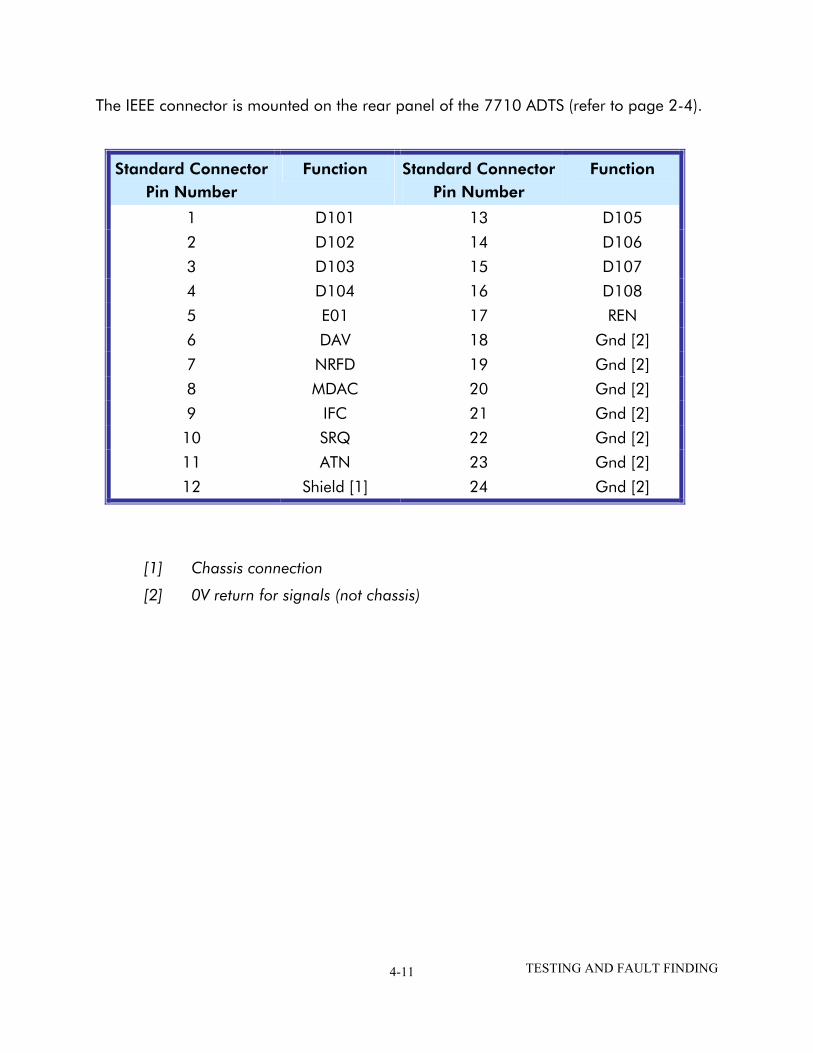
The IEEE connector is mounted on the rear panel of the 7710 ADTS (refer to page 2-4).
Standard Connector Pin Number
Function Standard Connector Pin Number
Function
1 D101 13 D105
2 D102 14 D106
3 D103 15 D107
4 D104 16 D108
5 E01 17 REN
6 DAV 18 Gnd [2]
7 NRFD 19 Gnd [2]
8 MDAC 20 Gnd [2]
9 IFC 21 Gnd [2]
10 SRQ 22 Gnd [2]
11 ATN 23 Gnd [2]
12 Shield [1] 24 Gnd [2]
[1] Chassis connection
[2] 0V return for signals (not chassis)
TESTING AND FAULT FINDING 4-11

THIS PAGE INTENTIONALLY LEFT BLANK
TESTING AND FAULT FINDING 4-12
SECTION 5.0 REFERENCE
5.1 INTRODUCTION This section includes a full description of each key function including references to
associated functions.
The available keys are: F1 - F4 ALT Ps SPEED Qc MACH Pt EPR ROC Ps RATE RATE TIMER HOLD RATE LEAK MEASURE/CONTROL GROUND PORT REMOTE PRINT EXECUTE TEST PROGRAM HELP SETUP NUDGE UP (↑) NUDGE DOWN (↓) 0 TO 9 - 000 CLEAR QUIT ENTER .
Double key presses give:
ABORT (CLEAR + ENTER) CONFIGURATION (F1 + SETUP)
5.2 MAIN PRESSURE DISPLAY F1 - F4
o
o
o
These function keys or soft-keys are used to select choices from menus. The menu choices may be shown directly over the keys or displayed as a list. When a menu is displayed, press the appropriate function key to select the required choice.
QUIT can be used to leave a menu without making a selection.
REFERENCE 5-1

ALT Ps o o o
o
o
o
o
o
o o o
o
o
o
* o
o
o
In aeronautical units (ft or m), this key selects an altitude display. In pressure units (mbar, inHg, etc.), this key selects a static pressure (Ps) display. SETUP, [UNITS] can be sued to change the units of display, if SETUP mode is not switched off. Before entering a new altitude or Ps aim, set the rate of change using the ROC or Ps RATE key. When in Control Mode (AIM display), enter a new altitude or Ps aim using the numeric keys. Use LEAK MEASURE/CONTROL to change between Control and Leak Measure mode.
SPEED Qc In aeronautical units (kts, km/h), this key selects an airspeed (CAS or TAS) display, in pressure units (mbar, inHg, etc.), this key selects dynamic pressure and the display shows (Qc). The airspeed can be displayed and entered as either Calibrated Airspeed (CAS, Vc) or True Airspeed (TAS, Vt).
NOTE: For testing purposes, Calibrated Airspeed equates to Indicated Airspeed (IAS).
The Pt temperature value affects the calculation of TAS. The value of Pt temperature, normally measured by the aircraft temperature sensor, can be changed by SETUP, SPEED, [Pt TEMPERATURE] only in FULL SETUP mode. Use SETUP, SPEED, [CAS/TAS] to select CAS or TAS. CAS/TAS can be changed in FULL SETUP mode. If the altitude aim is changed after the entry of CAS, the Mach and TAS aim values change while the CAS value remains unchanged*. If the altitude aim is changed after the entry of TAS or Mach, the CAS aim value changes while the TAS and Mach values remain unchanged*. If the Ps aim is changed after the entry of Qc, then the Pt aim value changes while the Qc remains unchanged*. If the Ps aim is changed, after the entry of Pt, then the Qc aim value changes while the Pt remains unchanged*.
The display shows = symbol next to the parameter that remains unchanged. SETUP, [UNITS] can be sued to change the units of display, if SETUP mode is not switched off. Before entering a new CAS or Qc aim, the rate of change should be set using the RATE key. When in Control Mode (AIM display), a new CAS or Qc can be entered using the numeric keys. Use LEAK MEASURE/CONTROL to change between Control and Leak Measure mode.
REFERENCE 5-2
MACH Pt o o o
o
o
o
*
o
o
o o o
o
o
o
o o
o
In aeronautical units (ft/kts or m/km/h), this key selects a Mach display. In pressure units (mbar, inHg, etc.), this selects a total pressure (Pt) display. If the altitude aim is changed after the entry of CAS, the Mach and TAS aim values change while the CAS value remains unchanged*. If the altitude aim is changed, after the entry of TAS or Mach, the CAS aim value changes while the TAS and Mach values remain unchanged*. If the Ps aim is changed after the entry of Qc, then the Pt aim value changes while the Qc remains unchanged*. If the Ps aim is changed after the entry of Pt, then the Qc aim value changes while the Pt remains unchanged*.
The display shows = symbol next to the parameter that remains unchanged.
Before entering a new Mach or Pt aim, set the rate of change of speed using the SPEED key followed by the RATE key. When in Control Mode (AIM display), a new Mach or Pt aim can be entered using the numeric keys. Use LEAK MEASURE/CONTROL to change between Control and Leak Measure mode.
EPR Engine Pressure Ratio (EPR) is only available in pressure units (mbar, inHg, etc.). The ADTS can be used to check EPR sensors and indicators. For EPR testing, use Ps as INLET pressure and EPR to set the ratio of OUTLET pressure (Pt) to INLET pressure. Before entering a new EPR aim, the rate of change should be set using the RATE key. When in Control Mode (AIM display), a new EPR aim can be entered using the numeric keys. Use LEAK MEASURE/CONTROL to change between Control and Leak Measure mode.
ROC Ps RATE In aeronautical units (ft or m), this key selects a Rate of Climb (ROC) or vertical speed display. In pressure units (mbar, inHg, etc.), this key selects a rate of change of Ps display. SETUP, [UNITS] can be used to change the units, if SETUP mode is not switched off. When in Control Mode (AIM display), a new ROC or Ps rate can be entered using the numeric keys. Use LEAK MEASURE/CONTROL to change between Control and Leak Measure mode.
REFERENCE 5-3

RATE TIMER o
o
o ˙ ˙ ˙ ˙
˙
˙
˙
˙
o
˙ ˙ ˙ ˙ ˙ ˙ ˙ ˙ ˙
o
˙
The RATE TIMER key starts an internal timer for one of three pre-defined times. On the completion of the time period, the average rate of change over the time period is displayed. Each selected TIME period can have an associated WAIT period to allow pressures to settle before the timing starts. The WAIT period counts down to zero before the TIME period starts. To use the RATE TIMER.
Press RATE TIMER. Press F1, F2 or F3 to select the required WAIT and TIME periods. The main pressure displays shows the WAIT or TIME period counting down. After timing, the timed average value, identified by a T directly to the right of the value, replaces the instantaneous rate value. In measure mode the display changes to show the timed rate of all associated parameters on the same screen. Pressing one of the set-point keys (e.g., ALT, ROC, SPEED, etc.,) or QUIT exits from this screen. At any time during rate timing or when a timed value is displayed, pressing the RATE TIMER key allows for either the restarting or canceling of the timing. When timing is cancelled, the rate displays revert to instantaneous values. The timed average value remains until a new aim is entered. During this time it is possible to view any parameter. The WAIT and TIME periods can be changed using SETUP, RATE TIMER, providing SETUP lock is not enabled.
HOLD When HOLD is pressed, a changing pressure is instantaneously held. Pressing HOLD again releases the pressure to continue to the aim value. The HOLD facility applies to both channels simultaneously and can be used to test pressure switches as follows:
Airspeed Switch Test Take the airspeed to a value just below the expected trip point. Enter a low rate of speed. Enter a new airspeed aim above the trip point. Immediately the switch trips, press HOLD. Read the airspeed value - this is the trip value for increasing airspeed. Enter a new airspeed aim below the expected trip value Immediately the switch trips, press HOLD. Read the airspeed value - this is the trip value for decreasing airspeed. Press HOLD again to release hold.
For both channels to start moving to new aims at the same time, use the following sequence:
Press HOLD.
REFERENCE 5-4

˙ ˙ ˙ ˙
o
o
o
o
Enter Ps channel aim. Enter Pt channel aim. Enter required rates. Press HOLD again to release hold.
HOLD is automatically released when entering Measure Mode.
RATE In aeronautical units (kts, km/h), this key selects a rate of change of airspeed (Rate CAS) display In pressure units (mbar, inHg, etc.), this key selects a rate of change of pressure (Rate Qc, Rate Pt or Rate EPR) display. The actual display depends on the parameter selected before pressing RATE.
The following rates are available in aeronautical units:
Key-press sequence Rate of change display
SPEED, RATE
MACH, RATE
Rate CAS*
Not available
*
o
Rate CAS is displayed with the airspeed in either CAS or TAS.
The following rates are available in pressure units:
Key-press sequence Rate of change display
Qc, RATE
Pt, RATE
EPR, RATE
Rate Qc
Rate Pt
Rate EPR
o
o
o
If SETUP mode is not switched off, SETUP [UNITS] can be used to change the units of display. A new rate aim can be entered using the numeric keys, if the unit is in Control Mode (AIM displayed). Use LEAK MEASURE/CONTROL to change between Control and Leak Measure mode.
If the automatic airspeed rate is selected (using SETUP, RATE) the airspeed rate is automatically adjusted to simultaneously achieve both altitude and airspeed aim values. This adjustment normally requires a reduction in the rate from the aim value; the rate does not exceed the aim value. When airspeed (not Qc) is automatically reduced, the display shows (A) after RATE CAS.
REFERENCE 5-5
LEAK MEASURE/CONTROL o
o o o
o o
o
o
o
o
o
o
o
o
o
This key switches between Control and Leak Measure mode.
NOTE: The pumps must be switched on before going to CONTROL mode.
The controllers can be switched off to measure leaks in the aircraft system When in leak measure mode, the display shows "LEAK MEASURE". Press LEAK MEASURE/CONTROL to switch the controllers on. The display briefly shows "REGAINING CONTROL" while the pressure controllers adjust to the system pressure. No significant pressure transients are produced when regaining control. When in control mode, the display shows "AIM value". Two safety systems are built-in to protect the aircraft systems during leak testing. These are Auto Leak recovery and Auto Limit recovery. Auto Leak recovery automatically regains control if the leak rate is too high on either channel. The trip values are set by the manufacturer to 3000 ft/min and 300 kts/min. Auto Leak recovery can be switched off using SETUP, LEAK MEASURE/CONTROL [AUTO LEAK]. If negative airspeed or Qc occurs in measure mode, the zero valve automatically opens for a period of one second to balance the airspeed or Qc. This only applies when the minimum CAS (or Qc) limit is zero.
NOTE: This only applies when the minimum CAS or Qc limit is zero.
Auto Limit recovery automatically regains control if the pressure on either channel leaks outside of the selected limits (except for negative airspeeds). Auto Limit recovery can be switched off using SETUP, LEAK MEASURE/CONTROL [AUTO LEAK].
NOTE: Auto Limit and Auto Leak recovery functions require the pump unit to be switched on.
GROUND This key enables a display of ground pressure or automatically controls the pressures in the aircraft system to local atmospheric pressure. The local atmospheric pressure is recorded by the ADTS during the power-up sequence. When GROUND is pressed, a menu gives a choice of three ground functions:
[GO TO GROUND] Selecting [GO TO GROUND] automatically enters an altitude or static aim equivalent to local atmospheric pressure (QFE) and an airspeed or dynamic pressure aim of zero. The system pressures will then be controlled towards these
REFERENCE 5-6

aims in the normal way, at the rates set by the ROC and RATE keys. At any time when going-to-ground, a new rate of change can be entered, the ADTS continues going-to-ground.
o
o
o
o
o
o
o
o
o
o
At any time during going-to-ground, a new value aim for ALT, CAS, TAS, Mach, Ps, Qc, Pt or EPR can be entered. This causes the procedure to stop and normal controlling operation to start. When the airspeed is zero and the Ps channel is close to ground, the QFE is re-measured to update the aim pressure, the display shows the message "CHECKING GROUND". The ADTS then reconnects to the system under test and equalizes the pressures. The Ps pressure is controlled to the QFE and the display shows the message "SAFE AT GROUND"; the ground and zero valves remain open so that the aircraft system permanently vents to atmosphere. No commands can be entered when these two messages are displayed. Press QUIT to continue with normal operation. The ground and zero valves then automatically close.
NOTE: The Go to Ground operates only in Control Mode.
[DISPLAY QFE] When [DISPLAY QFE] is selected, the local atmospheric pressure recorded during the power-up sequence is displayed as QFE. Press QUIT to return to the normal user display.
[DISPLAY QNH] When [DISPLAY QNH] is selected, the local atmospheric pressure recorded during power-up is converted to the equivalent sea level pressure and displayed as QNH together with the station (airfield) altitude. The station (airfield) altitude can be changed in FULL SETUP mode by using SETUP, GROUND.
REMOTE Exits Remote Mode. Remote Mode allows external devices to control the unit. As a result the keypad (except the Remote key) is disabled. If remote lock is disabled, pressing the remote key when the REMOTE message is not displayed forces the unit into remote mode as if a remote device assumed control of the unit.
NOTE: This may change operator settings such as the current limit set.
Refer to the option user manual for further details.
The ADTS contains a print facility to print the displayed readings together with up to nine user readings (e.g., Pilot, Copilot, Aux.).
REFERENCE 5-7
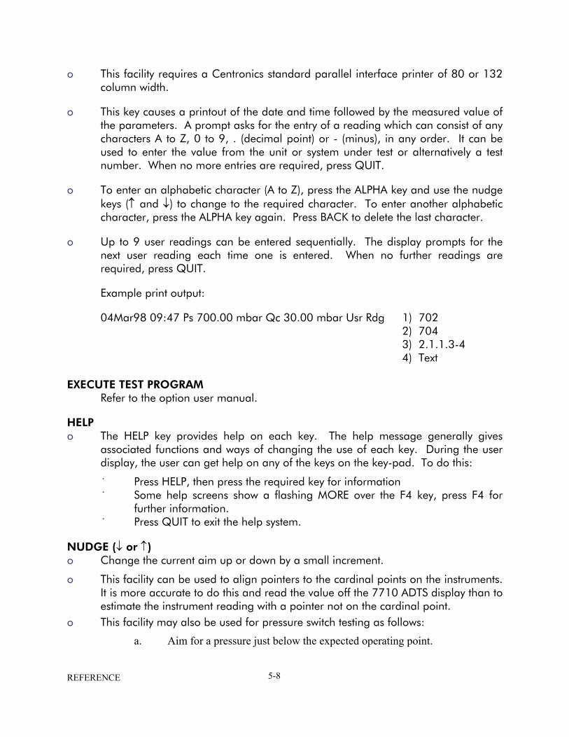
o
o
o
o
o
˙ ˙
˙
o
o
o
This facility requires a Centronics standard parallel interface printer of 80 or 132 column width.
This key causes a printout of the date and time followed by the measured value of the parameters. A prompt asks for the entry of a reading which can consist of any characters A to Z, 0 to 9, . (decimal point) or - (minus), in any order. It can be used to enter the value from the unit or system under test or alternatively a test number. When no more entries are required, press QUIT.
To enter an alphabetic character (A to Z), press the ALPHA key and use the nudge keys (↑ and ↓) to change to the required character. To enter another alphabetic character, press the ALPHA key again. Press BACK to delete the last character.
Up to 9 user readings can be entered sequentially. The display prompts for the next user reading each time one is entered. When no further readings are required, press QUIT.
Example print output:
04Mar98 09:47 Ps 700.00 mbar Qc 30.00 mbar Usr Rdg 1) 702 2) 704 3) 2.1.1.3-4 4) Text
EXECUTE TEST PROGRAM Refer to the option user manual.
HELP The HELP key provides help on each key. The help message generally gives associated functions and ways of changing the use of each key. During the user display, the user can get help on any of the keys on the key-pad. To do this:
Press HELP, then press the required key for information Some help screens show a flashing MORE over the F4 key, press F4 for further information. Press QUIT to exit the help system.
NUDGE (↓ or ↑) Change the current aim up or down by a small increment.
This facility can be used to align pointers to the cardinal points on the instruments. It is more accurate to do this and read the value off the 7710 ADTS display than to estimate the instrument reading with a pointer not on the cardinal point. This facility may also be used for pressure switch testing as follows:
a. Aim for a pressure just below the expected operating point.
REFERENCE 5-8

b. When the pressure is achieved, repeatedly press NUDGE (↑) until the switch operates.
c. Record the pressure reading shown on the display.
o o o
o
o
o o
o
o
o
o
o
See SET-UP, NUDGE to change the value of increment for the NUDGE facility. Holding down a NUDGE key automatically repeats the function. The nudge value can be sued for large increments e.g., 100 kts or 5000 ft to "step through" cardinal points on a test.
CAUTION: Make sure the nudge increment is set to a suitable value before using the nudge facility to change the aim value.
0 to 9 Use these keys for numeric entry. Press ENTER to complete numeric entry. Press CLEAR if a mistake is made during numeric entry. All data entry is based on over-writing the existing value. When the first numeric key is pressed, the existing number is replaced by the key pressed. At any time, the existing number may be recovered by pressing CLEAR.
-000 This key performs two functions during numeric entry. If it is the first numeric key pressed, it produces a minus sign for the entry of negative numbers. If it is not the first key pressed during numeric entry, it produces three zeros for fast entry of thousands, e.g. to enter -1000,
Press -000 (Display shows -) Press 1 (Display shows -1) Press -000 (Display shows -1000)
NOTE: When -000 is pressed during entry of an aircraft name for limits or in the Print facility, it always produces "-".
CLEAR/QUIT During numeric entry, CLEAR/QUIT removes the new number and restores the previously entered number.
NOTE: Once the ENTER key has been pressed, the old number cannot be restored.
When menus are displayed, CLEAR/QUIT exits the menu, generally to the previous display. For those displays containing a [SAVE] option, changes made before pressing CLEAR/QUIT are ignored. For all other displays, changes are saved when CLEAR/QUIT is pressed. When warning messages are displayed, pressing CLEAR/QUIT removes the message.
REFERENCE 5-9

ENTER o
o
o o
o
o
o
o
o
o
The ENTER key completes numeric entry.
CLEAR + ENTER (ABORT) When CLEAR and ENTER are pressed simultaneously, the ADTS restarts from the power-up sequence. When the keys are pressed all output valves immediately close. The ABORT function should only be used as a last resort:
a. When a restart is required after the system has shutdown displaying an error message.
b. As an emergency measure. If the system is restarted by pressing ABORT, it vents to atmosphere during the power-up sequence.
5.3 SETUP Pressing the SETUP key causes the system to enter a SETUP mode preset in the configuration mode. The following section describes the three functions of setup: FULL, MINIMUM and OFF. The FULL SETUP allows access to all set-up functions. MINIMUM SETUP allows access to some set-up functions, the OFF function prevents access to the set-up functions.
FULL SET-UP FULL SETUP allows access to secondary functions that do not have an assigned key. Any parameter changed under SETUP reverts to the default settings on power-down. The CONFIGuration mode may be used to change the default settings so that the ADTS powers up in the required state. Almost all set-up parameters are also available under CONFIG. In addition, some parameters are only available under CONFIG. Certain parameters under SETUP can be locked from CONFIG to prevent inadvertent changes such as aircraft limits at power-up with a particular set of limits that must not be changed. If a change to a locked parameter is attempted, a warning message is displayed. Once SETUP is pressed, set-up functions are available from soft keys and directly by pressing certain keys. To use the set-up menus, press SETUP, then select the required menu choice using the appropriate function key. To use direct key SETUP, press SETUP, then press the required key. The direct key set-up on each key relates to the normal user mode function of that key. Further menus are used under certain direct key set-ups.
NOTE: The Quick Reference Section of this manual provides details of the set-up menus and keys.
REFERENCE 5-10

o
o
o
o
o
o
Once a parameter has been changed under SETUP, use QUIT to return to the preceding menu. After all required parameters have been changed, repeatedly press QUIT until the display shows the main pressure display. The following section describes each SETUP function. Intermediate menus are not described.
SETUP, [UNITS] Use [NEXT] or [PREV] to step through the available units until the display shows the required units. Select [SAVE] and then press [QUIT] to make the selection. The available units are:
ft and kts (includes Mach) ft and mph (includes Mach) m and km/h (m/min) (includes Mach) m and km/h (m/S) (includes Mach) m and km/h (hm/min) (includes Mach) mbar inHg mmHg inH2O 4oC inH2O 20oC inH2O 60oF psi hPa kPa
SETUP, [LIMITS] The ADTS is preprogrammed with the manufacturer's STANDARD and CIVIL limit sets. Different sets of additional aircraft limits can be programmed using the CONFIG mode. SETUP, [LIMITS] allows the selection of the set of limits to be used, each set of limits is identified by its aircraft name. Use [NEXT] or [PREV] to step through the aircraft names select [SEL] and press QUIT when the display shows the required name. Use CONFIG, [LIMITS] to program the sets of limits. Each set of limits includes:
Max ALT Min Ps Min ALT Max Qc Max CAS Min Qc Min CAS Max Rat Ps Max Mach Max Rate Qc Max ROC ARINC limits on or off Max Rate CAS Altitude correction value Max Ps
REFERENCE 5-11

o
o
o
o
˙ ˙ ˙ ˙ ˙
o
o
o
o
o
o
o
The set of limits used at power-up (default) can be selected using CONFIG, [LIMITS], [DEFAULT AIRCRAFT]. The default aircraft settings can be locked using CONFIG, [LIMITS], [LOCK AIRCRAFT] so that the operator cannot change the limits. If the selected set of limits result in the measured pressures being outside the limits, the display shows the warning message "OUTSIDE LIMITS GO TO GROUND" the Ps and Pt channels should be taken to ground or to pressures within the new selected limits. This warning message is also displayed if the pressures measured directly after power-up are outside the limits used at power-up. After selecting a set of limits, the altitude correction value can be changed using SETUP, ALT. The maximum Mach limit can be changed or turned off using SETUP, MACH.
SETUP, [OSC] The ADTS has an oscillation facility that causes the pressure to oscillate about the aim value at a user defined frequency and amplitude.
Select oscillation channel Ps or Pt. Select [AMPL/FREQ] and enter the required amplitude and frequency. Select [START] to start oscillation. Select [STOP] to stop oscillation at the end of a half cycle. Select [FREEZE] to stop oscillation immediately.
SETUP, [MORE], [DUAL CH./Pt ONLY] Dual channel is the normal mode of operation where both Ps (static) and Pt (pitot) channels are connected to the unit or aircraft system under test. To test instruments such as airspeed indicators with only the Pt (pitot) channel connected, use SETUP, [MORE] [DUAL CH./Pt ONLY] and select [Pt ONLY]. When using [Pt ONLY], the blanking cap must be removed from the Ps (static) channel so that Ps is open to atmosphere. All the functions associated with the Ps channel are disabled. To return to dual channel operation, select SETUP, [MORE], [DUAL CH./Pt ONLY], [DUAL CHANNEL] and connect Ps (static) channel to the unit or aircraft system under test. The channel controllers must be in measure mode when changing to and from Pt only. The Ps (static) pressure must be within ±10 mbar of the recorded QFE to select Pt only.
SETUP, [MORE], [DISPLAYS/OPTIONS], [DISPLAY TYPE] The display can be configured for SINGLE, DUAL or TRIPLE displays. The key press sequence changes the display parameters, the 2nd key press column shows the parameter that changes on entry of a numeric value. The tables show all available parameter combinations with an associated keypress sequence.
REFERENCE 5-12

1st Key Press
2nd Key Press
Upper Display
Lower Display
ALT ALT Any key SPEED MACH* SPEED SPEED MACH MACH
SPEED MACH ROC RATE RATE MACH ALT ALT SPEED
ALT ALT ALT CAS or TAS MACH MACH ALT ALT MACH
CAS or TAS MACH ROC RATE CAS "Rate Mach not available" CAS/TAS SPEED MACH SPEED
*Mach is the parameter which changes on numeric entry
Aeronautical units dual display
1st Key Press
2nd Key Press
Upper Display
Lower Display
Ps Ps Ps Any key Qc Pt EPR Pt Qc Pt EPR Qc
Qc Pt EPR RATE Ps RATE RATE RATE Qc Ps Ps Ps Pt
Ps Ps Ps Ps Qc Pt EPR Pt Ps Ps Ps Pt
Qc Pt EPR RATE Ps RATE Qc RATE Pt RATE EPR Qc Qc Pt EPR Qc
Pressure units dual display
1st Key Press
2nd Key Press
Display
Any key Any key Any key SPEED Any key
SPEED MACH ROC RATE ALT
ALT, CAS or TAS ALT, CAS or TAS, MACH ALT, CAS or TAS, ROC ALT, CAS or TAS, RATE CAS ALT, CAS or TAS
Aeronautical units triple display
REFERENCE 5-13

1st Key Press
2nd Key Press
Display
Any key //Any key /Ps Any key Qc Pt EPR Qc EPR
Qc Pt EPR ROC RATE RATE RATE Ps Ps
Ps, Qc Ps, Qc, Pt Ps, EPR Ps, Qc, RATE Ps Ps, Qc, RATE Qc Ps, Pt, RATE Pt Ps, EPR, RATE EPR Ps, Qc Ps, EPR
Pressure units triple display
o
o
o o
o o
o
o
o
At the end of rate timing, the rate of change on both channels are displayed for aeronautical units ROC and RATE CAS and for pressure units RATE Ps, RATE Pt and RATE Qc.
NOTE: This is the same for all display modes.
Option Displays
The key presses function, for the option displays, in the same way as a "single display" (i.e., the single displayed parameter comes from the last key press), with the lower half of the display screen showing any available data from the option.
SETUP, [MORE], [DISPLAY/OPTIONS][SENSOR ZERO] This function allows access to sensor zero options . Start will begin a zero procedure on the Ps and Pt channels. This will continue till a timeout occurs, or the zero is complete. Vac allows setting the maximum vacuum level allowed before a zero will occur. Dry will begin a dryout procedure on the Ps and Pt channels. This will continue until ZERO or ABRT is pressed.
SETUP, [MORE], [DISPLAYS/OPTIONS], [OPTIONS] This function allows changes to option hardware that may be fitted. - See option manuals for further details. If an option that is not fitted is selected the display shows the error message "Option Hardware not fitted". Refer to the option user manual.
SETUP, [MORE], [CLOSE OUTPUT VALVES] This function closes the Ps and Pt valves to enable leak checking of the internal pneumatics of the ADTS, with the aircraft system isolated, but still connected. All the normal functions of the ADTS may be used in this mode.
REFERENCE 5-14
NOTE: For safety, the output valves can only be closed when the ADTS is at ground.

SETUP, [MORE], [OPEN OUTPUT VALVES] o
o
o
o
o
o
o
o
o
o
o
o
o
This function opens the Ps and Pt output valves after using the [CLOSE OUTPUT VALVES] function.
NOTE: For safety, the output valves can only be opened when the ADTS is at ground.
SETUP, [MORE], [SYSTEM SELF TEST] This function starts a self-test, the system pressures must be at ground pressure and the system in Leak Measure mode selected. The self-test is the same test routine as power-up.
NOTE: At the end of the self-test the output valves will be open.
SETUP, ALT (Figures 5-1 and 5-2) This function allows the altitude correction value to be changed. If altitude correction is in use the display shows "AC" (after warm-up) in the lower right hand corner. The altitude correction facility corrects for the pressure difference when the ADTS and the aircraft system are at different heights. Enter the height of the aircraft system above the ADTS reference level. If the ADTS front panel is vertical, use the reference level shown on the front panel. The units of entry are the current units or default aeronautical units, see CONFIG, [UNITS], [AERONAUTICAL].
SETUP, SPEED, [AUTO ZERO] This function enables or disables the auto zero function. When enabled, this optimizes airspeed accuracy at low airspeeds. When enabled the ADTS performs an auto zero when the following conditions are met: 1. Ps and Pt pressures are stable. 2. If in control mode, a zero airspeed or Qc aim has been achieved. 3. If in leak measure mode, the airspeed is less than 20 knots (or Qc equivalent).
The auto zero will be initiated within one minute of achieving a new aim value and every five minutes thereafter. The auto zero sequence can be interrupted at any time by entering a new command over the keypad or option interface. The controllers must be in measure mode when enabling or disabling auto zero.
SETUP, SPEED, [CAS/TAS] This function changes the airspeed display between Calibrated Airspeed (CAS or Vc) and True Airspeed (TAS or Vt). For testing purposes, CAS is equivalent to Indicated Airspeed (IAS). The value of TAS displayed depends on the Pt temperature. See SETUP, SPEED, [Pt TEMPERATURE].
REFERENCE 5-15
rack-mounted ADTS
reference level
reference level
FIGURE 5-1 ALTITUD
SET-UP, SPEED, [Pt TEMPERTURE] o
o
o
o
o ˙ ˙ ˙
o
o
˙ ˙ ˙ ˙ ˙ ˙
This function allows the valuecalculation of TAS. Enter the Pitot temperature mthe units shown on the displayThe default units may be chan
SET-UP, MACH This function allows the Machlimit comes from the current aTo change the limit enter a nu
Select [OFF] to disable Select [ON] to enable tSelect [DEFAULT] to res
SET-UP, RATE TIME This function allows the WAITRATE TIME function.
To change the times:
Select the function to bEnter the WAIT time in Enter 00:00 if a wait isSelect TIME. Enter the TIME in minutPress QUIT.
REFERENCE
components under test
E CORRECTION RACK M
of Pt temperature to be
easured by the aircraft's . ged using CONFIG, [UNI
limit to be changed or ircraft limits. meric value or select as fothe Mach limit. he Mach limit. tore the Mach limit from t
and TIME times to be se
e changed: F1, F2 or F3 minutes and seconds. not required.
es and seconds.
5-16
negative altitude correction level
OUNTING
entered and is used in the
Pitot temperature sensor in
TS], [TEMPERATURE].
disabled. The initial Mach
llows:
he aircraft limits in use.
t for F1, F2, and F3 of the

˙
o
o o
o
o
o
o
o
o o
o
o o
o
o
Select another WAIT/TIME or press QUIT.
See the RATE TIMER for further details.
SET-UP, RATE This function selects automatic airspeed rate control ON or OFF. If the automatic airspeed rate is selected (using SETUP, RATE) the airspeed rate is automatically adjusted to simultaneously achieve both altitude and airspeed aim. This adjustment normally requires a reduction in the rate from the aim value; the rate does not exceed the aim value. When airspeed is automatically reduced, the display shows RATE CAS aim as (A). This function only applies when using Aeronautical units (ft and kts, ft and mph, m and km/h (m/min), m and km/h (m/s), m and km/h (km/min).
SETUP, LEAK MEASURE CONTROL, [AUTO LEAK] This function enables or disables the AUTO LEAK RECOVER facility. See LEAK MEASURE/CONTROL for further details.
SETUP, LEAK MEASURE CONTROL [AUTO LIMIT] This function enables or disables AUTO LIMIT RECOVERY. See LEAK MEASURE/CONTROL for further details.
SETUP, GROUND This function enables the station (airfield altitude to be entered and is used when displaying QNH. See GROUND for further details.
Enter the station (airfield) altitude in the units shown on the display. See CONFIG, [UNITS], [AERONAUTICAL] for default units.
SETUP, [PORT] This function sets up the port option. If an option that is not fitted is selected the display shows the error message "Option Hardware not fitted". Refer to the Line Switching Unit, User Manual.
SETUP, PRINT, [DATE/TIME] This function allows the system time and date to be set. The time and date is maintained by a battery-backed clock when the ADTS is switched off. Use [TIME] or [DATE] to select between time or date. To change the time or date, enter all six digits and press ENTER.
The date format can be either US (mm/dd/yy) or UK (dd/mm/yy) using CONFIG, [MORE], [DATE FORMAT]. The time format is hh:mm:ss.
SETUP, HELP This function provides help on the SETUP key.
REFERENCE 5-17
SETUP, NUDGE (↓ or ↑) o
o
o o o
o
o
o
o
o
o
This function allows the authority of the NUDGE key to be adjusted for every parameter. When SETUP, NUDGE is pressed, the display shows the value of NUDGE for the parameter last displayed. Enter a new value to replace the present value. Use [NEXT] or [PREV] to display other parameters. Press QUIT when the NUDGE values of all required parameters have been changed. In aeronautical units, only the aeronautical parameters are available. These are: ALT CAS/TAS MACH ROC RATE CAS In pressure units, only the pressure parameters are available. These are: Ps Pt Qc EPR RATE Ps - RATE Qc RATE EPR The nudge value can be used for large increments, e.g., 100 kts or 5000 ft to "step through" cardinal points on a test.
CAUTION: Make sure the nudge increment is set to a suitable value before using the nudge facility to change the aim value.
MINIMUM SETUP Minimum set-up allows limited access to secondary functions that do not have an
assigned key. Any parameter changed under SETUP reverts to the default settings at power-down.
The CONFIGuration mode may be used to change the default settings so that the ADTS powers-up in the required state.
SETUP, [UNITS], [AERO] The current operating limits are changed to the default aeronautical units. These units can be programmed using CONFIG, [UNITS], [AERO].
SETUP, [UNITS], [PRESS] The current operating limits are changed to the default pressure units. These units can be programmed using CONFIG, [UNITS], [PRESS].
SETUP, [LIMITS] The ADTS is preprogrammed with the manufacturer's STANDARD and CIVIL limit sets. Different sets of additional aircraft limits can be programmed using the CONFIG mode. SETUP, [LIMITS] allows the selection of the set of limits to be used, each set of limits is identified by its aircraft name.
Use [NEXT] or [PREV] to step through the aircraft names select [SEL] and press QUIT when the display shows the required name.
REFERENCE 5-18

o
o
o
o
o
o
o o
o o
o
o
Use CONFIG, [LIMITS] to program the sets of limits. Each set of limits includes: Max ALT Min Ps Min ALT Max Qc Max CAS Min Qc Min CAS Max Rate Ps Max Mach Max Rate Qc Max ROC ARINC limits on or off Max Rate CAS Altitude correction value Max Ps
The set of limits used at power-up (default) can be selected using CONFIG, [LIMITS], [DEFAULT AIRCRAFT]. The default aircraft settings can be locked using CONFIG, [LIMITS], [LOCK AIRCRAFT] so that the operator cannot change the limits. If the selected set of limits result in the measured pressures being outside the limits, the display shows the warning message "OUTSIDE LIMITS GO TO GROUND" the Ps and Pt channels should be taken to ground or to pressures within the new selected limits. This warning message is also displayed if the pressures measured directly after power-up are outside the limits used at power-up. After selecting a set of limits, the altitude correction value can be changed using SETUP, ALT. The maximum Mach limit can be changed or turned off using SETUP, MACH.
SETUP, ALT (Figures 5-1 and 5-2) This function allows the altitude correction value to be changed. If altitude correction is in use the display shows "AC" in the lower right hand corner after warm-up. The altitude correction facility corrects for the pressure difference when the ADTS and the aircraft system are at different heights. Enter the height of the aircraft system above the ADTS reference level. The units of entry are the current units or default aeronautical units, see CONFIG, [UNITS], [AERONAUTICAL].
SETUP, [PORT] This function sets the port option. If an option that is not fitted is selected the display shows the error message "Option Hardware not fitted". Refer to the Line Switching Unit User Manual.
SETUP, HELP This function provides help on the SETUP key.
5.4 CONFIGURATION
REFERENCE 5-19
Any parameters changed in any mode of SETUP revert to the default settings when power is removed from the system. The CONFIGuration mode may be used to

change the default settings so that the ADTS powers-up in a specified state. Almost all SETUP parameters are also available in CONFIG; other parameters are only available in CONFIG.
o
o
˙ ˙ ˙
˙
o
o o
o
o
Certain parameters in SETUP can be locked using CONFIG to prevent inadvertent changes. For example, units used in a servicing procedure for a specific aircraft type can be set to power-up with a set of limits that must not be changed. In addition to this, the SETUP menus can be locked out or access restricted to prevent changes to operating parameters.
Procedure To enter CONFIG, hold down F1 then press SETUP. CONFIG may be password protected using a four digit PIN. If PIN protected, the display prompts for entry of the PIN. Press each digit of the PIN in turn (ENTER is not required) as each digit is entered, an asterisk appears. If an incorrect PIN is entered, the complete PIN is requested again.
When the correct PIN is entered, the CONFIG menu appears. The PIN may be changed using CONFIG, -000. CONFIG functions are available both from soft keys and by directly pressing certain keys. To use the menu, press the appropriate function key to select the required menu item. To use direct key CONFIG, press the key for the key function to be configured e.g. press CONFIG SPEED to configure true airspeed. Further menus may be used under direct key configuration. Once a parameter has been changed under CONFIG, use QUIT to return to the previous menu. After all required parameters have been changed, repeatedly press QUIT until the display shows the normal operating mode.
Functions In the following section, each description of CONFIG function is headed by the menu/key sequence required to select it. Intermediate menus are not described. Many of the functions are equivalent to the set-up functions; refer to SETUP for the details of the function.
CONFIG, [UNITS] This function allows the default units to be configured. The default [AERONAUTICAL] units are used at power-up for the Altitude (and Airspeed) display. The default units are also used for the limits entry in CONFIG and entry of any altitude or airspeed related functions in SETUP or CONFIG e.g., airfield altitude or altitude correction. The default [PRESSURE] units are used for limits entry in CONFIG and entry of any pressure values in SETUP or CONFIG. The default [TEMPERATURE] units are used for entry of temperature values in SETUP or CONFIG.
REFERENCE 5-20

o
o
o
o o o
o
o
o
o
o
The default [AERONAUTICAL] and [PRESSURE] are set in MINIMUM SETUP, [UNITS].
CONFIG, [AIRCRAFT LIMITS], [EDIT LIMITS], [EDIT EXISTING] This function allows existing sets of limits to be configured.
Use [NEXT] or [PREV] to select the set of limits by aircraft name when the display shows the required aircraft limits, press [SEL] to edit the limit values. Use [NEXT] or [PREV] to step through each limit or associated parameter in turn. Enter a new numeric value to change a limit. Press QUIT when all required changes have been made and select [YES] to save changes. The parameters are:
Name Max Ps Max Alt Min Ps Min Alt Max Qc Max CAS Min Qc Min CAS Max Rate Ps Max Mach Max Rate Qc Max ROC ARINC Limits Max Rate CAS Altitude Correction
NOTE: The system defined "STANDARD", "CIVIL" and "MAX" limit sets cannot be redefined. Edited limit sets must be saved under a different name.
NAME The aircraft name is used for selecting the set of limits in SETUP or CONFIG. Enter up to 8 characters using 0 to 9, - (minus), . (decimal point) and any alphabetic characters in any order or combination. To enter an alphabetic character (A to Z), press ALPHA and use the nudge keys to change to the required character. Press ALPHA again to enter another alphabetic character. Press BACK to delete the last character. When editing text use the QUIT key to cancel editing.
MIN ALT, MAX ALT, MIN CAS, MAX CAS These are the fundamental aeronautical units limits.
MAX MACH This limit only applies in aeronautical mode. It can be sued to set a maximum Mach (e.g., Mach 1.05). If a Mach limit is not required, enter a high value (e.g., 10). The Mach limit can be changed or disabled in full SETUP mode using [SET UP], [MACH], see SET UP, MACH for further details on Mach limits.
REFERENCE 5-21

MAX ROC, MAX RATE CAS o
o
o
o
o
o o o
o
o
These limits are the maximum rate of change for altitude and airspeed and only apply in aeronautical units.
MIN Ps, MAX Ps, MIN Qc, MAX Qc These are the fundamental pressure units limits.
MAX RATE Ps, MAX RATE Qc These limits are the maximum rate of change for Ps and Qc and only apply in pressure units.
ARINC LIMITS (Figure 5-3) ARINC 565 operating limits are enabled by setting ARINC LIMITS ON and implemented as shown in Fig. 5-3. Due to the shape of the altitude/airspeed envelope, these limits cannot be implemented using the above altitude, airspeed and Mach limits. Using the [ON/OFF] function key select the required ARINC limits ON or OFF. When used in combination with other limits, the most restricting limits apply. If ARINC limits are selected and any of the other limits are greater than the values of the ARINC limits a display message requests confirmation that the lower, ARINC limit, is to be used before the limit is saved.
ALTITUDE CORRECTION The altitude correction value for a specific aircraft may be entered as well as its limits. The altitude correction value can be changed during operation in full and minimum SETUP modes using [SETUP], [ALT]. See [SETUP], [ALT] for further details on altitude correction.
REFERENCE 5-22

0 100 200 300 400 500 600
1.0 MACH
190 450
AL
TIT
UD
E F
EE
T (
TH
OU
SAN
DS)
60
55
50
40
30
20
15
10
-1000 ft
-10
Maximum altitude rate 20000 feet/min. Maximum airspeed rate 1 Mach/min.
FIGURE 5-2
SAVING LIMITS ˙
˙
˙
˙
˙
When all limits and assocediting screen. If changes have been madsaving the changes. If the system detects any eror editing system-defined lto be corrected.
CONFIG, [AIRCRAFT LIMITS], [EThis function makes a set using CONFIG, [AIRCRAFTa new name. This is a qumaximum system limits. The system displays an erro
AIRSPEED (KNOTS)
ARINC 565 OPERATING LIMITS
iated functions are set, press [QUIT] to exit the limit
e, the display shows a request for confirmation before
rors (e.g., duplicate aircraft names, values out of range imits) the display changes to the edit screen for the error
DIT LIMITS], [MAX LIMITS] of maximum limits; a set of MAX limits can be edited LIMITS], [EDIT LIMITS], [EDIT EXISTING] and saved with ick method for setting-up a set of limits similar to the
r message if MAX limits already exist.
REFERENCE 5-23
CONFIG, [AIRCRAFT LIMITS], [EDIT LIMITS], [EDIT NEW] o
o
o o
o o
o
o
o
o
o
This function is identical to [EDIT EXISTING] and creates a new set of limits. Default values are taken from "Standard" limits. See [EDIT EXISTING] above for further details.
CONFIG, [AIRCRAFT LIMITS], [CLEAR LIMITS] This function clears an existing set of limits. Use [NEXT] or [PREV] to display the name of the limits. Select [SEL] to clear the limits followed by [YES].
CONFIG, [AIRCRAFT LIMITS], [LOCK AIRCRAFT] This function prevents changes to the default limits. If lock is [ON], no changes to the power-up DEFAULT aircraft limits can be made from SETUP.
CONFIG, [AIRCRAFT LIMITS], [DEFAULT AIRCRAFT] This function selects the set of limits used at power-up. Use [NEXT] or [PREV] to display the name of the required limits. Select [SEL].
CONFIG, [MORE], [DUAL CH./Pt ONLY] CONFIG equivalent of SETUP function.
CONFIG, [MORE], [DISPLAY/OPTIONS], [DISPLAY TYPE] CONFIG equivalent of SETUP function.
CONFIG, [MORE], [DISPLAY/OPTIONS], [OPTIONS] Refer to the option user manual.
CONFIG, [MORE], [DATE/FORMAT] This functions allows the display date format to be selected from [DMY] (dd/mm/yy) or [MDY] (mm/dd/yy).
CONFIG, [MORE], [SETUP MODE] This function enables, disables or limits access to the secondary functions. There are three set-up modes:
FULL This mode provides complete access to all secondary functions when the SETUP key is pressed. All pressure and aeronautical units can e selected.
MINIMUM This mode provides limited access to the secondary functions when the SETUP key is pressed. This prevents access to error recovery, rate timers etc. Units can only be changed between two pre-selected types, for full details see Section 5.3.
OFF This mode prevents access to all secondary functions. All operating parameters must be set from CONFIGuration. For full details see this Section (5.4).
REFERENCE 5-24

CONFIG, SPEED, [AUTO ZERO] o
o
o
o
o
o
o
o
o
o
o
o
CONFIG equivalent of SETUP function
CONFIG, SPEED, [CAS/TAS] CONFIG equivalent of SETUP function.
CONFIG, SPEED, [Pt TEMPERATURE] CONFIG equivalent of SETUP function.
CONFIG, RATE TIME CONFIG equivalent of SETUP function.
CONFIG, RATE CONFIG equivalent of SETUP function.
CONFIG, LEAK MEASURE, [AUTO LEAK ON/OFF] CONFIG equivalent of SETUP function, see LEAK MEASURE/CONTROL for details.
CONFIG, LEAK MEASURE, [AUTO LEAK LOCK] Prevents changes to AUTO LEAK setting in SETUP.
CONFIG, LEAK MEASURE, [AUTO LIMIT ON/OFF] CONFIG equivalent of SETUP function, see LEAK MEASURE/CONTROL for details.
CONFIG, LEAK MEASURE, [AUTO LIMIT LOCK] Prevents changes to AUTO LIMIT setting in SETUP.
CONFIG, GROUND CONFIG equivalent of SETUP function.
CONFIG, PORT Refer to option user manual.
CONFIG, REMOTE
CAUTION: Changing between sets of limits can cause damage to sensitive instruments. Entering CONFIG disables lock out. There are two sets of limits "REMOTE" and "LOCAL".
This function disables the front panel keypad and allows the ADTS to be controlled by a remote device such as a PC. The front panel display shows the "REMOTE" message. To return to "local" control (key-pad) press LOCAL/REMOTE key. The remote device can disable this key.
NOTE: Some ATE systems may require the ADTS set in the remote mode before the remote device starts communicating. If remote lock is disabled, set the ADTS while in local control by pressing the REMOTE/LOCAL key.
REFERENCE 5-25
CONFIG, ETP, [AUTO RUN] o
o
o
o
o
Forces a down-loaded test program to operate (Execute Test Program) on power up. See test Program Manager User Manual for further details.
CONFIG, ETP, [DELETE] Removes a down-loaded test program from non-volatile memory. See test Program Manager User Manual for further details.
CONFIG, NUDGE CONFIG equivalent of SETUP function.
CONFIG, 000 This function enables, changes or disables the CONFIG PIN code protecting access to CONFIG menu. When enabled, the PIN must be entered before it can be changed. The prompt asks for "Enter existing PIN", then a new PIN can be entered. This must comprise four numeric digits. Once entered, the prompt asks again for the new PIN to protect against data entry errors. To disable the PIN, so that CONFIG can be entered without a PIN, enter 0000.
NOTE: Access to maintenance functions may also be PIN protected. This PIN number is not the same as the CONFIG PIN.
REFERENCE 5-26

SECTION 6.0 APPENDIX A
Appendix A - Associated Publications
A1 Technical Manuals
This appendix lists the Ruska manuals and publications referenced in this manual.
SCPI IEEE 488 Manual
Air Data Test Set ADTS
TPM User Manual K250
Test Program Manager Version 4 for Windows
APPENDIXES 6-1

THIS PAGE INTENTIONALLY LEFT BLANK
APPENDIXES 6-2

APPENDIX B MATERIALS
B1 Purpose and Scope
This appendix lists materials required for the operator to maintain the ADTS. The item number and name in the table identifies the item in the maintenance tasks (for example, "Use a soft bristle brush, item 4, Appendix B").
The description provides further information required to identify the item.
Item Number
Part Number Item Name, Description
1 - Cloth, Cotton, Lint-Free
2 - Alcohol, Isopropyl (MIL-A-10428, Grade A)
3 - Detergent, Mild, Liquid
4 - Brush, Soft-bristle (MIL-B-43871)
NOTE: Equivalent substitutes can be used.
TABLE 6-1 MATERIALS LIST
APPENDIXES 6-3

THIS PAGE LEFT INTENTIONALLY BLANK
APPENDIXES 6-4
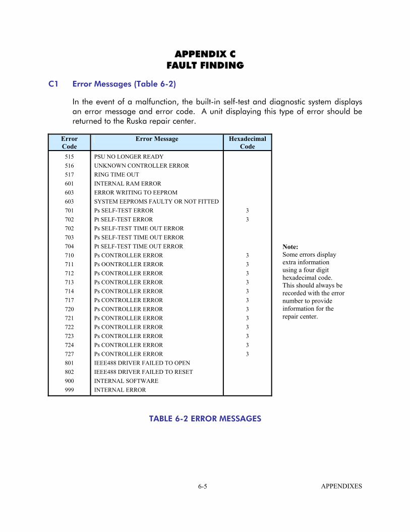
APPENDIX C FAULT FINDING
C1 Error Messages (Table 6-2)
In the event of a malfunction, the built-in self-test and diagnostic system displays an error message and error code. A unit displaying this type of error should be returned to the Ruska repair center.
Error Code
Error Message Hexadecimal Code
515 516 517 601 603 603 701 702 702 703 704 710 711 712 713 714 717 720 721 722 723 724 727 801 802 900 999
PSU NO LONGER READY UNKNOWN CONTROLLER ERROR RING TIME OUT INTERNAL RAM ERROR ERROR WRITING TO EEPROM SYSTEM EEPROMS FAULTY OR NOT FITTED Ps SELF-TEST ERROR Pt SELF-TEST ERROR Ps SELF-TEST TIME OUT ERROR Ps SELF-TEST TIME OUT ERROR Pt SELF-TEST TIME OUT ERROR Ps CONTROLLER ERROR Ps OONTROLLER ERROR Ps CONTROLLER ERROR Ps CONTROLLER ERROR Ps CONTROLLER ERROR Ps CONTROLLER ERROR Ps CONTROLLER ERROR Ps CONTROLLER ERROR Ps CONTROLLER ERROR Ps CONTROLLER ERROR Ps CONTROLLER ERROR Ps CONTROLLER ERROR IEEE488 DRIVER FAILED TO OPEN IEEE488 DRIVER FAILED TO RESET INTERNAL SOFTWARE INTERNAL ERROR
3 3
3 3 3 3 3 3 3 3 3 3 3 3
Note: Some errors display extra information using a four digit hexadecimal code. This should always be recorded with the error number to provide information for the repair center.
TABLE 6-2 ERROR MESSAGES
APPENDIXES 6-5

C2 Warning Messages (Table 6-3)
The following table lists the warning messages with the probable cause and action to be taken.
No. Message Probable Cause Action 2 INVALID USER INPUT The numeric value entered was
outside the allowed range. Re-enter value within allowed range.
3
OPERATE CAL ENABLE ON STATUS PANEL
Calibration started before removing calibration enable plate on the front panel.
Refer to the main fault finding chart in the service manual.
4 ONLY VALID IN CONTROL MODE
Selection not allowed in Leak Measure mode.
Select controller on.
210
Ps SOFT START TIMEOUT
The Ps controller has failed to go into control mode.
Select CONTROL again. If fails, again, refer to the main fault-finding chart in the service manual.
212
Ps PRESSURE FAIL
The Ps controller has detected loss of supply pressure and automatically switched all channels to measure mode. This can occur at very high rates of pressure change in large Volume systems if the pumps cannot produce enough pressure.
Restore pressure supply BEFORE going to control mode again. Refer to the main fault-finding chart in the service manual.
213
Ps VACUUM FAIL
The Ps controller has detected loss of supply vacuum and automatically switched all channels to measure mode. This can occur at very high rates of pressure change in large volume systems if the pumps cannot product enough vacuum.
Restore vacuum supply BEFORE going to control mode again. Refer to the main fault-finding chart in the service manual.
220
Pt SOFT START TIMEOUT
The Pt controller has failed to go into control mode.
Select CONTROL AGAIN. If fails again, refer to the main fault-finding chart in the service manual.
222
Pt PRESSURE FAIL
The Pt controller has detected loss of supply pressure and automatically switched all channels to measure mode. This can occur at very high rates of pressure change in large volume systems if the pumps cannot produce enough pressure.
Restore pressure supply BEFORE going to control mode again. Refer to the main fault-finding chart in the service manual.
TABLE 6-3 WARNING MESSAGES
APPENDIXES 6-6

No. Message Probable Cause Action 223 Pt VACUUM FAIL The Pt controller has detected loss of
supply vacuum and automatically switched all channels to measure mode. This can occur at very high rates of pressure change in large volume systems if the pumps cannot produce enough vacuum.
Restore vacuum supply BEFORE going to control mode again.
301 LEAK RATE TOO HIGH REGAINING CONTROL
Control mode automatically regained for aircraft safety as leak rates too high.
Correct leak and retest.
302 OUTSIDE LIMITS REGAINING CONTROL
Control mode automatically regained for aircraft safety as the measured values have drifted outside of the operating limits due to leaks.
Correct leaks and retest. If leak Ps, ensure that nominal Qc pressure is applied (e.g. 200 kts to avoid negative airspeed).
303 ZERO OFFSET TOO LARGE
The zero offset measured during auto-zero was outside of established limits.
Perform zeroing procedure per Appendix E1.
304 INITIALIZING BLANK SYSTEM EEPROMS
This only occurs if new EEPROMS have been fitted or on main system software upgrade.
If message occurs during normal operation, return to Ruska repair center.
305 OUTSIDE LIMITS GO TO GROUND
Measured pressure is outside new limits selected or power-up limits.
Control pressures to within limits.
306 SWITCH PUMPS ON Cannot select control mode with the pumps off.
Switch pumps on.
307 COMMUNICATION RING FAULT - PACKET IS CORRUPT
Internal error. If the fault can be repeated, return to Ruska repair center.
308 UPDATING SYSTEM EEPROMS
Software upgrade. Wait 1 minute.
309 CANNOT CONTROL Failed pump test. Check system limits.
310 PUMP TEST FAILED Pump not achieving limits. Set lower limits.
TABLE 6-3 WARNING MESSAGES (CONTINUED)
APPENDIXES 6-7

THIS PAGE LEFT INTENTIONALLY BLANK
APPENDIXES 6-8
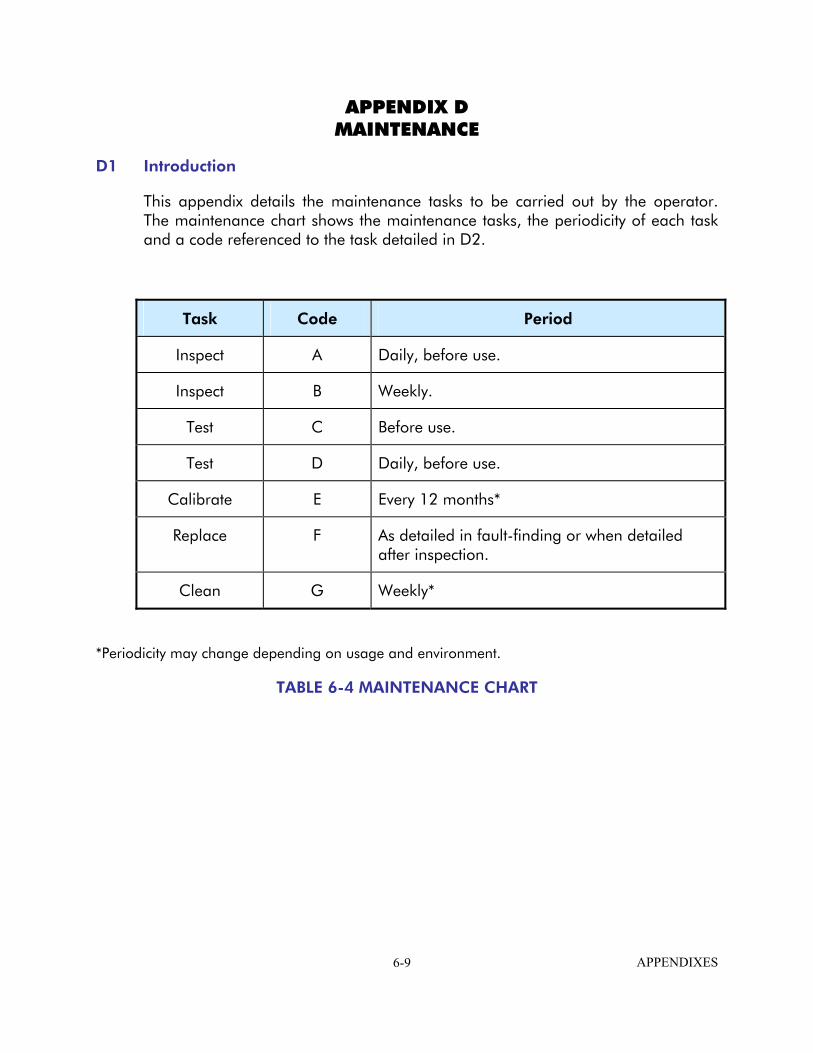
APPENDIX D MAINTENANCE
D1 Introduction
This appendix details the maintenance tasks to be carried out by the operator. The maintenance chart shows the maintenance tasks, the periodicity of each task and a code referenced to the task detailed in D2.
Task Code Period
Inspect A Daily, before use.
Inspect B Weekly.
Test C Before use.
Test D Daily, before use.
Calibrate E Every 12 months*
Replace F As detailed in fault-finding or when detailed after inspection.
Clean G Weekly*
*Periodicity may change depending on usage and environment.
TABLE 6-4 MAINTENANCE CHART
APPENDIXES 6-9
D2 Maintenance Tasks
A Visually inspect the unit for obvious signs of damage and check that all the equipment is present; record any deficiencies.
B Visually inspect the pneumatic output connectors for damage. Inspect the small o-ring on each pneumatic output connector for cuts and any signs of wear; replace as necessary. Visually inspect pneumatic hoses, electrical cables for cuts, splits and damage; replace as necessary.
C Before use, power-up the unit as detailed in Section 3.2. Check the date of the last calibration and, if necessary, refer to task E. Record any error messages and refer to Appendix C.
D Daily and before use, carry out the SST detailed in Section 4.
E Normal calibration period is 12 months. When calibration is due, the unit should be withdrawn from service and returned to the Ruska Service Center. The date of calibration is stored in the unit and displayed in the power-up sequence and on a label on the front panel. Do not use a unit with out-of-date calibration. Engineering authority may change the periodicity of calibration depending on usage and the operating environment.
F As detailed in fault finding or when detailed after inspection, replace the listed item in Table 6-8.
G Clean the unit every week. Clean the front panel with a damp lint-free cloth (item 1, Appendix B) and mild liquid detergent (item 3, Appendix B). Remove any stubborn dirt using isopropyl alcohol (item 2, Appendix B) and allow to dry. Clean all pneumatic connectors with a soft brush (item 4, Appendix B) and allow to dry.
APPENDIXES 6-10
APPENDIX E ZERO AND CALIBRATION
E1 Zero Procedure
Equipment Needed
Vacuum Pump Pressure Supply
Setup
Connect Vacuum Supply to Vacuum Supply Port. Connect Pressure Supply to Pressure Supply Port.
The 7710 ADTS must be in Measure Mode. The 7710 ADTS must be at a stable operating temperature.
Procedure
Confirm that the WARMUP message no longer appears in the lower right corner of the display. When WARMUP is displayed the 7710 ADTS has not reached a stable operating temperature.
NOTE: From a cold start, it could require 2-3 hours for the temperature to stabilize.
On the front panel, press the SETUP key. From the Menu, press F4-More, F2-DISPLAY/OPTIONS, then F2-SENSOR ZERO.
This will display the START/VAC/DRY menu.
Start Zero
To start the Zero process, press F1-STRT. The 7710 ADTS displays the pressure reading for both channels (Ps and Pt), and the Required Vacuum Level on the front panel. The Zero function does not directly use the pressure reading, but the displayed pressure value should decrease as vacuum is applied and becomes stable. Depending on the previous Zero, this displayed value may or may not be close to 0.
When a Zero is successfully completed on each channel, the displayed pressure for that channel will be near 0, depending on the actual vacuum applied. When both channels successfully complete the Zero, the 7710 ADTS will release vacuum and return to ground pressure. It may loop through 'Checking Ground' and "Equalizing System Pressures' screens several times before displaying the 'Safe at Ground' screen. When this is displayed, press the CLEAR/QUIT key.
APPENDIXES 6-11

This returns to the START/VAC/DRY menu. Press the CLEAR/QUIT key. The 'ARE YOU SURE' screen is displayed. Press F1-YES. Press CLEAR/QUIT three times. This returns to the Measure Mode display.
The 7710 ADTS will timeout if the Zeroing process has not been completed within 10 minutes. In these cases, warnings like 'Zero not Started' or 'Zero not completed' will be displayed. Usually the cause of these warnings will be the failure of the vacuum to reach a stable value below the required vacuum level. In these cases, the recommended solution is to place the 7710 ADTS in DRY mode (see below). To exit from the error screen, press the CLEAR/QUIT key. When the 7710 ADTS is 'Safe at Ground', press CLEAR/QUIT to return to the START/VAC/DRY screen.
A 'Zero Offset Too Large' warning may be displayed during boot sequence or while operating. This indicates that the Zero procedure should be performed.
Change Vacuum Level
This option sets the maximum vacuum value allowed during zero. Vacuum must be less than this level before stability is checked during the zeroing process.
To change the Vacuum value, press F3. Enter a new vacuum level in microns. Acceptable values are 0-350 microns. Press the ENTER key. The 7710 ADTS will return to the START/VAC/DRY Screen.
Dry 7710 ADTS
This option allows vacuum to be applied to the 7710 ADTS without being limited by a timeout. No Zero is done. If a 7710 ADTS has not been under an applied vacuum for some length of time, it is recommended that the 7710 ADTS be placed in DRY mode for a minimum of 3 hours before doing a Zero. A longer time may be required.
To dry the 7710 ADTS, press F4 from the START/VAC/DRY screen. This opens several valves so that vacuum is applied to the sensor. The displayed pressure should decrease as vacuum is applied.
To exit DRY mode, press F2 ABORT. The 7710 ADTS releases the vacuum and returns to ground pressure. It will display the 'Checking Ground' screen and the 'Equalizing System Pressures' screen, then the 'Safe at Ground' screen. Pressing CLEAR/QUIT returns to the START/VAC/DRY screen.
APPENDIXES 6-12

E2 - Calibration Procedures
E2.1 WINCAL Software
The WINCAL software main menu has six options: o File o Setup o Calibrate o View o Window o Help
File Menu
Exit will exit the WinCal software.
Setup
Select Communications to setup the RS-232 port.
Select Options to define the Display Resolution, Pressure Units, and Sensor Configuration. The Sensor configuration includes the Enable, Address, and Password for the sensor.
Calibrate
Calibrate Vacuum will start the vacuum calibration procedure
Calibrate Pressure Sensor will start the pressure calibration sensor.
Zero Pressure Sensor will start the zeroing sensor.
View
Coefficients will display the Sensor coefficients for attached sensors.
Window
Displays a list of open windows.
Help
Displays options for reading the Help files. Help includes detailed instructions for calibrating the 7710 Sensor.
APPENDIXES 6-13

E2.2 Equipment needed for Calibration
o
o o o o o o
o
o
o
o
o
o
o
o
o
o
o
o
Computer with Windows 95/98, 100 MHz minimum and one available communications port WinCal Calibration Software Serial Cable - with any necessary adaptors Metering Valve Adaptor with Metering Valve (see Figure E2-1) Vacuum Standard Vacuum Supply Pressure Supply
Setup
Turn off the 7710 ADTS
Remove top cover of the 7710 ADTS (12 screws).
Attach the metering valve adaptor to the Vacuum supply port on the back panel of the 7710 ADTS. See Figure E2-1. This setup is only required to attain two distinct vacuum levels for calibrating the on-board vacuum sensors. If the vacuum sensors are not to be calibrated, the vacuum source may be directly attached to the vacuum supply port.
Attach vacuum pump to metering valve adaptor.
Remove Swagelok cap from Ps Channel Connector at inlet to the Sensor Box inside the 7710 ADTS. Attach Pressure Standard to this connector. Attach Vacuum Measurement Standard to the Pressure Standard Connection. A valve must be attached that can shut off pressure to the vacuum sensor.
Turn off Vacuum Control Switch.
Set Channel Select switch to the operate (middle) position.
Attach a serial cable to the DB25 connector on the 7710 ADTS rear panel. Attach the other end of the serial cable to a communications port on the PC.
Turn on 7710 ADTS. The 7710 ADTS will need to warm up before doing a calibration. The WARMUP message will be displayed until the 7710 ADTS temperature is stable.
NOTE: From a cold start this could require 2-3 hours.
Turn on vacuum pump.
Change the Channel Select switch from Operate to the Calibrate Ps setting. The front panel screen will display an error message. This is normal.
Turn the Vacuum switch to ON.
APPENDIXES 6-14

o
o
o
o
The WINCAL Software should be installed on a PC. The software is provided on a disk, or may be downloaded from the Ruska Website www.ruska.com. It is installed by running SETUP.EXE from the RUN option of the START menu and following the on-screen instructions.
Start the WINCAL software. If error message is displayed, check all connections and switch positions.
Verify the Full Scale value for the Sensor. This information is at the top of many of the screens of the WINCAL Software.
After calibration the 7710 can be reassembled by reversing the steps. Make sure the Vacuum switch is OFF and the Channel Select switch is in the OPERATE (middle) position.
CALIBRATION
Vacuum Transducer
1. Select Calibrate Vacuum form the menu bar.
2. Adjust the Vacuum Supply metering valve so that the Vacuum Standard value is within the limits defined by the "Apply" value (i.e. 100 +/- 50 micorns).
3. When the Vacuum Standard value is stable, enter this value into the "Applied" field and then press F6 to accept.
4. Repeat steps 2 & 3 for the second calibration point (i.e., 300 +/- 50 microns).
Sensor Zero
NOTE: If a Pressure Calibration will be done, this does not need to be done as a separate step. It is included in the Pressure Calibration.
1. Select Zero Pressure Sensor from the menu bar.
2. Wait for the Pressure Status and temperature to become Stable. Pressure Status may show 'Out of Range'. If this occurs check the setup. If 'Out of Range' remains, contact Ruska Instrument Corporation Service center. Vacuum Level should be below 350 microns and stable.
3. Click Zero Sensor to continue with Zero.
4. The Sensor will take 30-40 seconds to Zero. When it is complete, it will update the Last Zero Date. Click Close to close the window.
Sensor Calibration
1. Select Calibrate Pressure Sensor from the menu bar.
2. Click the Zero button to zero sensor. Follow the Sensor Zero directions (above) to zero Sensor.
APPENDIXES 6-15

3. Adjust the Pressure Standard so it is within the limits defined by the 'Apply' value.
4. When the Pressure Standard is stable, enter this value into the 'Applied' field and then click the Accept Button to accept data point.
5. Repeat steps 3 & 4 for the second calibration point.
To calibrate the Pt Channel, change the Operate Switch to the Calibrate Pt position and set the Vacuum switch to ON. Repeat the Calibration Procedures for the Vacuum Gauge, Sensor Zero and Sensor Calibration as needed.
Verification of Calibration
Calibration Verification can be done from the front panel of the 7710 ADTS. To do this the system must be set to Operation configuration
o o o
o
o o o o o o
Set the Vacuum Switch to OFF. Set the Operation Switch to the middle position. Reset the 7710 ADTS by pressing the CLEAR/QUIT and ENTER keys at the same time. Wait for the 7710 ADTS to reboot. It may display various warning messages. Press the CLEAR key to bypass these messages. Press and hold F1, then press F4. When the Date is displayed, press ENTER. When the Calibration menu is displayed, select Check Calibration by pressing F2. Select F1 to verify the Ps Channel, or F2 to verify the Pt Channel. Select F4 for External Source. Verify the selected channel.
APPENDIXES 6-16
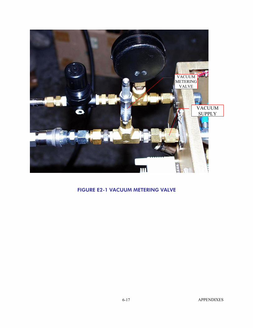
VACUUM METERING
VALVE
VACUUM SUPPLY
FIGURE E2-1 VACUUM METERING VALVE
APPENDIXES 6-17

THIS PAGE INTENTIONALLY LEFT BLANK
APPENDIXES 6-18