ru - 1ja0pa1tvpl63v04fj2l0oby-wpengine.netdna-ssl.com
TRANSCRIPT

g z x h
dD
C
B
r
ds
d Ds
D
ds
r
B
RU
ds
d Ds
D
B
RJ
r
r
d Ds
D
Br
r
CYLINDRICAL ROLLER BEARING CATALOGTIMKEN CYLINDRICAL ROLLER BEARING CATALOG


TIMKEN CYLINDRICAL ROLLER BEARING CATALOG 1
CYLINDRICAL ROLLER BEARING CATALOG INDEX
TIMKEN OVERVIEW. . . . . . . . . . . . . . . . . . . . . . . . . . . . . . . . . . . . . . . . . 2
SHELF LIFE POLICY . . . . . . . . . . . . . . . . . . . . . . . . . . . . . . . . . . . . . . . . . 6
CYLINDRICAL ROLLER BEARING INTRODUCTION . . . . . . . . . . . . . . 8
ENGINEERING
Bearing Types and Cages . . . . . . . . . . . . . . . . . . . . . . . . . . . . . . . . . . . 10
Metric System Tolerances . . . . . . . . . . . . . . . . . . . . . . . . . . . . . . . . . . 13
Mounting, Fitting, Setting and Installation Practices . . . . . . . . . . . 16
Shaft and Housing Fits . . . . . . . . . . . . . . . . . . . . . . . . . . . . . . . . . . . . . 22
Operating Temperatures . . . . . . . . . . . . . . . . . . . . . . . . . . . . . . . . . . . . 40
Heat Generation and Dissipation . . . . . . . . . . . . . . . . . . . . . . . . . . 43
Torque . . . . . . . . . . . . . . . . . . . . . . . . . . . . . . . . . . . . . . . . . . . . . . . . . . . 44
Lubrication . . . . . . . . . . . . . . . . . . . . . . . . . . . . . . . . . . . . . . . . . . . . . . . 45
CYLINDRICAL ROLLER BEARINGS
Introduction. . . . . . . . . . . . . . . . . . . . . . . . . . . . . . . . . . . . . . . . . . . . . . . 55
Nomenclature . . . . . . . . . . . . . . . . . . . . . . . . . . . . . . . . . . . . . . . . . . . . . 56
One-Row Metric ISO Series . . . . . . . . . . . . . . . . . . . . . . . . . . . . . . . . . 58
One-Row Standard Series . . . . . . . . . . . . . . . . . . . . . . . . . . . . . . . . . . 72
Full-Complement (NCF) . . . . . . . . . . . . . . . . . . . . . . . . . . . . . . . . . . . . . 74
Two-Row . . . . . . . . . . . . . . . . . . . . . . . . . . . . . . . . . . . . . . . . . . . . . . . . . 76
Four-Row . . . . . . . . . . . . . . . . . . . . . . . . . . . . . . . . . . . . . . . . . . . . . . . . . 82
HJ Series . . . . . . . . . . . . . . . . . . . . . . . . . . . . . . . . . . . . . . . . . . . . . . . . . 96
Inner Rings (IR) . . . . . . . . . . . . . . . . . . . . . . . . . . . . . . . . . . . . . . . . . . . 100
5200, A5200 Metric Series . . . . . . . . . . . . . . . . . . . . . . . . . . . . . . . . . 102
Download 3D Models and 2D Drawings at cad.timken.com. •

2 TIMKEN CYLINDRICAL ROLLER BEARING CATALOG
OVERVIEW
TIMKEN
A
CHOOSE TIMKEN STRENGTHYou can count on the strength of Timken expertise and quality
products to help you increase your productivity and gain a
competitive edge in your industry.
When you choose Timken, you receive more than high-quality
products and services; you acquire a worldwide team of highly
trained and experienced associates, eager to help you keep
production rates high and downtime low.
Whether it is a wheel assembly for a family vehicle, bearings
outfitted for a deep-sea oil drilling rig, repair services for rail
bearings or steel for an aircraft engine shaft, we supply the
products and services you need that help keep the world
turning.
FRICTION MANAGEMENT SOLUTIONS – A TOTAL SYSTEMS APPROACHYour industry is ever-changing, from the evolution of advanced
motion-control systems to the demands from your customers.
Turn to us to stay ahead of the curve.
We use our friction-management know-how to offer solutions
that maximize performance, fuel-efficiency and equipment
life. We also offer integrated services that extend well beyond
bearings, including condition monitoring systems and services,
encoders and sensors, seals, premium lubricants
and lubricators.
Timken’s wide range of friction management solutions can
include evaluations of your entire system – not just individual
components. This provides cost-effective solutions to help you
reach specific application goals. Working together, we help
you meet these demands and ensure all your systems
run smoothly.
• Download 3D Models and 2D Drawings at cad.timken.com.

TIMKEN CYLINDRICAL ROLLER BEARING CATALOG 3
OVERVIEW
TIMKEN
A
TECHNOLOGY THAT MOVES YOUInnovation is one of our core values, and we’re known for our
ability to solve engineering challenges.
We focus on improving performance in the most difficult
applications, and we’re passionate about creating technical
solutions and services that help your equipment perform faster,
harder, smoother and more efficiently.
To do this, we invest in:
• People, attracting and hiring scholars, engineers and
specialists from across the globe who are experts in
mechanical power transmission, antifriction bearing design,
tribology, metallurgy, clean steel production, precision
manufacturing, metrology, and engineered surfaces and
coatings.
• Tools, including state-of-the-art laboratories, computers
and manufacturing equipment.
• The Future, identifying new concepts that make you
standout in your industry for years to come. Our ongoing
investment in research and development activities allows
us to grow our capabilities, expand our product and service
portfolio, and deliver value over the long term.
We’re committed to finding new avenues for system
sustainability. In the area of power density,
we’re creating systems where we replace
larger, more cumbersome components with
smaller, more efficient bearings to help
improve systems’ performance.
Wherever you’re located, you can count
on us at technology centers in North
America and Asia - as well as in our
manufacturing facilities and field offices
on six continents - to develop ideas and
resources to transform your concepts
into reality.
Download 3D Models and 2D Drawings at cad.timken.com. •

4 TIMKEN CYLINDRICAL ROLLER BEARING CATALOG
OVERVIEW
TIMKEN
A
A BRAND YOU CAN TRUSTThe Timken brand stands for quality, innovation and
dependability.
We take pride in the quality of our work, and you
gain the peace-of-mind of knowing that each
box contains an industry-trusted product. As our
founder, Henry Timken, said, “Don’t set your name to
anything you will ever have cause to be ashamed of.”
We continue this mindset through the Timken Quality
Management System (TQMS). With TQMS, we promote
continuous quality improvements in our products and
services to our global operations and supply chain networks.
It helps us ensure that we’re consistently applying demanding
quality management practices throughout the company. We
also register each of our production facilities and distribution
centers to the appropriate quality system standards for the
industries they serve
ABOUT THE TIMKEN COMPANYThe Timken Company keeps the world turning with innovative
friction management and power transmission products and
services that are critical to help hard-working machinery
to perform efficiently and reliably. In 2011, Timken achieved
sales of $5.2 billion from operations in 30 countries with
approximately 20,000 people.
• Download 3D Models and 2D Drawings at cad.timken.com.

TIMKEN CYLINDRICAL ROLLER BEARING CATALOG 5
OVERVIEW
TIMKEN
A
ABOUT THIS CATALOGTimken offers an extensive range of bearings and accessories
in both imperial and metric sizes. For your convenience, size
ranges are indicated in millimeters and inches. Contact your
Timken sales representative to learn more about our complete
line for the special needs of your application.
USING THIS CATALOGWe are committed to providing our customers with maximum
service and quality. This publication contains dimensions,
tolerances and load ratings, as well as an engineering section
describing fitting practices for shafts and housings, internal
clearances, materials and other bearing features. It can
provide valuable assistance in the initial consideration of the
type and characteristics of the bearing that may best suit your
particular needs.
Every reasonable effort has been made to ensure the accuracy
of the information contained in this writing, but no liability is
accepted for errors, omissions or for any other reason.
Timken products are sold subject to Timken’s terms and
conditions of sale, including its limited warranty and remedy.
Please contact your Timken sales engineer with questions.
CATALOG FEATURESDimensional and load rating data, within the various types and
styles of bearings, is organized by size.
ISO and ANSI/ABMA, as used in this publication, refer to
the International Organization for Standardization and the
American National Standards Institute/American Bearing
Manufacturers Association.
NOTE
Product performance is affected by many factors beyond the control of Timken. Therefore, the suitability and feasibility of all designs and product selection should be validated by you. This catalog is provided solely to give you, a customer of Timken or its parent or affiliates, analysis tools and data to assist you in your design. No warranty, expressed or implied, including any warranty of fitness for a particular purpose, is made by Timken. Timken products and services are sold subject to a Limited Warranty.
You can see your Timken engineer for more information.
Download 3D Models and 2D Drawings at cad.timken.com. •
6 TIMKEN CYLINDRICAL ROLLER BEARING CATALOG
OVERVIEW
TIMKEN
SHELF LIFE AND STORAGE OF GREASE-LUBRICATED BEARINGS AND COMPONENTSTimken guidelines for the shelf life of grease-lubricated rolling
bearings, components and assemblies are set forth below.
Shelf life information is based on test data and experience.
Shelf life should be distinguished from lubricated bearing/
component design life as follows:
SHELF LIFE POLICYShelf life of the grease-lubricated bearing/component
represents the period of time prior to use or installation. The
shelf life is a portion of the anticipated aggregate design life. It
is impossible to accurately predict design life due to variations
in lubricant bleed rates, oil migration, operating conditions,
installation conditions, temperature, humidity and extended
storage.
Shelf life values, available from Timken, represent a maximum
limit – and assume adherence to the Timken suggested storage
and handling guidelines. Deviations from Timken’s storage and
handling guidelines may reduce shelf life. Any specification or
operating practice that defines a shorter shelf life should be
used. Timken cannot anticipate the performance of the grease
lubricant after the bearing or component is installed or placed
in service.
TIMKEN IS NOT RESPONSIBLE FOR THE SHELF LIFE OF ANY BEARING/COMPONENT LUBRICATED BY ANOTHER PARTY
European REACH compliance
Timken-branded lubricants, greases and similar products sold
in stand-alone containers or delivery systems are subject to
the European REACH (Registration, Evaluation, Authorization
and Restriction of CHemicals) directive. For import into the
European Union, Timken can sell and provide only those
lubricants and greases that are registered with ECHA
(European CHemical Agency). For further information,
please contact your Timken engineer.
STORAGETimken suggests the following storage guidelines for its
finished products (bearings, components and assemblies,
hereinafter referred to as “Products”):
• Unless directed otherwise by Timken, Products should be
kept in their original packaging until they are ready to be
placed into service.
• Do not remove or alter any labels or stencil markings on the
packaging.
• Products should be stored in such a way that the packaging
is not pierced, crushed or otherwise damaged.
• After a Product is removed from its packaging, it should be
placed into service as soon as possible.
• When removing a Product that is not individually pack-
aged from a bulk pack container, the container should be
resealed immediately after the Product is removed.
• Do not use Product that has exceeded its shelf life as
defined in Timken’s shelf life guidelines statement.
• The storage area temperature should be maintained
between 0º C (32º F) and 40º C (104º F); temperature
fluctuations should be minimized.
• The relative humidity should be maintained below
60 percent and the surfaces should be dry.
• The storage area should be kept free from airborne
contaminants such as, but not limited to, dust, dirt, harmful
vapors, etc.
• The storage area should be isolated from undue vibration.
• Extreme conditions of any kind should be avoided.
Inasmuch as Timken is not familiar with a customer’s
particular storage conditions, these guidelines are strongly
suggested. However, the customer may very well be required
by circumstance or applicable government requirements to
adhere to stricter storage requirements.
• Download 3D Models and 2D Drawings at cad.timken.com.

TIMKEN CYLINDRICAL ROLLER BEARING CATALOG 7
OVERVIEW
TIMKEN
Proper maintenance and handling practices are critical. Always follow installation instructions and
maintain proper lubrication.
Never spin a bearing with compressed air. The rollers may be forcefully expelled.
WARNINGFailure to observe the following warnings could
create a risk of death or serious injury.
A
Most bearing
types are typically
shipped protected
with a corrosion-
preventive compound
that is not a lubricant.
Such bearings may be
used in oil-lubricated
applications without
removal of the corrosion-
preventive compound. When
using some specialized grease
lubrications, it is advisable to remove
the corrosion-preventive compound before
packing the bearings with suitable grease.
Some bearing types in this catalog are pre-packed with
general purpose grease suitable for their normal application.
Frequent replenishment of the grease may be necessary for
optimum performance. Care must be exercised in lubricant
selection, however, since different lubricants are often
incompatible.
When specified by the customer, other bearings may be
ordered pre-lubricated.
Upon receipt of a bearing shipment, ensure that the bearings
are not removed from their packaging until they are ready
for mounting so that they do not become corroded or
contaminated. Bearings should be stored in an appropriate
atmosphere in order that they remain protected for the
intended period.
Any questions concerning shelf life or storage should be
directed to your local sales office.
Warnings for this product line are found in this catalog
and posted on www.timken.com/warnings
Download 3D Models and 2D Drawings at cad.timken.com. •

CYLINDRICAL ROLLER BEARING INTRODUCTION
8 TIMKEN CYLINDRICAL ROLLER BEARING CATALOG
TIMKEN ® CYLINDRICAL ROLLER
BEARINGS - Offering Selection and Superior Performance
Your success depends on the performance of your equipment,
especially when it faces harsh environments and high radial
loads. To keep your uptime high and downtime low, turn to
Timken® cylindrical roller bearings.
THE TIMKEN DIFFERENCECooler operating temperatures. High durability. Longer-lasting
performance. A wide range of sizes. Our brand stands for
high quality, reliability and outstanding performance. Your
applications may run better, produce more and experience
improved uptime when equipped with Timken cylindrical roller
bearings. As a result, you see a reduction in overall operating
costs.
Each bearing is backed by a skilled team of global experts,
providing you with the industry’s best design, application
knowledge and 24/7 field-engineering support.
DESIGN FEATURESFeaturing premium cages, unique internal geometries,
enhanced surface textures and compact designs, these
bearings meet or exceed expectations for longer bearing life.
A radial cylindrical roller bearing consists of an inner and/or
outer ring and a complement of controlled-contour cylindrical
rollers. Depending on the style of bearing, either the inner or
the outer ring will have two roller-guiding ribs. The other ring,
separable from the assembly, has one rib or none. The ring
with two ribs axially locates the position of the roller assembly.
The diameters of these ribs may be used to support the roller.
One of the ribs may carry light thrust loads when an opposing
rib is provided in the mating ring.
ENSURING QUALITYThe quality of our materials is just as important as our
designs in helping machines run more efficiently. We’re the
only bearing manufacturer in the world that makes our own
steel. By using clean, high-alloy steel in our cylindrical roller
bearings, we can ensure the overall quality of our product.
We also implement our Worldwide Quality Standards in
every manufacturing facility so that each bearing meets
the same performance standards wherever in the world it’s
manufactured.
PRODUCT OFFERINGYou can select product from a complete line of high-
performance cylindrical roller bearings. Our product line
includes full-complement, one-, two- and four-row designs, all
developed to meet your application requirements. Sizes range
from 60 mm (2.5591 in.) to 2000 mm (78.7402 in).
Updates are made periodically to this catalog. Visit
www.timken.com for the most recent version of the Cylindrical
Roller Bearing Catalog.
TABLE 1. RADIAL CYLINDRICAL ROLLER BEARING TYPES AND SIZES
Bearing Type Available Size Range
Single-row 60 - 2000 mm (2.3622 - 78.7402 in.)
Full-complement (NCF) 100 - 2000 mm (3.9370 - 78.7402 in.)
Two-row 80 - 2000 mm (3.1496 - 78.7402 in.)
Four-row 140 - 2000 mm (4.7244 - 78.7402 in.)
INDUSTRY PRESENCETimken cylindrical roller bearings effectively reduce friction and
help transmit power in applications like:
• Power generation
• Oil fields
• Crop shears
• Gear drives
• Hoists
• Metals construction
• Mining
• Aggregate processing
• Pumps
• Rolling mills
• Wheel-end planetaries
• Wind energy
• Other industrial equipment
• Download 3D Models and 2D Drawings at cad.timken.com.

ENGINEERING
TIMKEN CYLINDRICAL ROLLER BEARING CATALOG 9
ENGINEERINGThe following topics are covered within this
engineering section:
• Cylindrical roller bearing design types.
• Cage design types.
• Fitting practice and mounting recommendations.
• Lubrication recommendations.
This engineering section is not intended to be
comprehensive, but does serve as a useful guide in
cylindrical roller bearing selection.
To view the complete engineering catalog, please visit
www.timken.com. To order the catalog, please contact
your Timken engineer and request a copy of the Timken
Engineering Manual, order number 10424.
Download 3D Models and 2D Drawings at cad.timken.com. •

BEARING TYPES AND CAGES
ENGINEERING
10 TIMKEN CYLINDRICAL ROLLER BEARING CATALOG
A RADIAL CYLINDRICAL ROLLER BEARING TYPES AND CAGESRadial cylindrical roller bearings can offer higher radial load capacity than other bearing designs.
The Timken Company offers a wide range of full complement, one -, two -, and four-row designs
to meet various application requirements.
RADIAL CYLINDRICAL ROLLER BEARINGS
STANDARD STYLES
Timken® cylindrical roller bearings consist of an inner and outer
ring, a roller-retaining cage, and a complement of controlled-
contour cylindrical rollers. Depending on the type of bearing,
either the inner or the outer ring has two roller-guiding ribs. The
other ring is separable from the assembly and has one rib or
none. The ring with two ribs axially locates the position of the
roller assembly. The ground diameters of these ribs may be used
to support the roller cage. One of the ribs may be used to carry
light thrust loads when an opposing rib is provided.
The decision as to which ring should be double ribbed is normally
determined by considering assembly and mounting procedures
in the application.
Type NU has double-ribbed outer and straight inner rings. Type
N has double-ribbed inner and straight outer rings. The use of
either type at one position on a shaft is ideal for accommodating
shaft expansion or contraction. The relative axial displacement
of one ring to the other occurs with minimum friction while the
bearing is rotating. These bearings may be used in two positions
for shaft support if other means of axial location are provided.
Type NJ has double-ribbed outer and single-ribbed inner
rings. Type NF has double-ribbed inner and single-ribbed outer
rings. Both types can support heavy radial loads, as well as
light unidirectional thrust loads. The thrust load is transmitted
between the diagonally opposed rib faces in a sliding action.
When limiting thrust conditions are approached, lubrication can
become critical. Your Timken engineer should be consulted for
assistance in such applications. When thrust loads are very light,
these bearings may be used in an opposed mounting to locate
the shaft. In such cases, shaft endplay should be adjusted at
time of assembly.
Type NUP has double-ribbed outer and single-ribbed inner ring
with a loose rib that allows the bearing to provide axial location
in both directions. Type NP has a double-ribbed inner ring and
a single-ribbed outer ring with a loose rib. Both types can carry
heavy radial loads and light thrust loads in both directions. Factors
governing the thrust capacity are the same as for types NJ and
NF bearings.
A type NUP or NP bearing may be used in conjunction with type
N or NU bearings for applications where axial shaft expansion is
anticipated. In such cases, the N or NU bearing accommodates
the shaft expansion. The NUP or NP bearing is considered the
fixed bearing because the ribs restrict the axial movement of
the rolling element. The fixed bearing is usually placed nearest
the drive end of the shaft to minimize alignment variations in the
drive. Shaft endplay, or float, is determined by the axial clearance
in the fixed bearing.
Types NU, N, NJ, NF, NUP and NP conform to ISO and DIN
standards for loose rib rings (thrust collars) and typical industry
diameters over or under roller.
The cylindrical roller bearing part numbers are in accordance
with ISO 15. They are composed of four digits, the first two digits
identify the dimensional series and the last two digits of the part
number are the bore size divided by 5. In the dimensional series,
the first digit is the width series and the second is the diameter
(outer) series. The width series increase width in the sequence
8 0 1 2 3 4 5 6 7. The diameter series increase radial section in
the sequence 7 8 9 0 1 2 3 4.
Types having an R prefix are similar in construction to their N
counterparts. However, they were designed to conform to ABMA
standards.
Inch-size bearings are identified by the letter I in the part number.
RIU, for example, indicates an inch bearing while RU indicates
the equivalent style in metric dimensions.
NU, RIU, RU N, RIN, RN NJ, RIJ, RJ NF, RIF, RF NUP, RIT, RT NP, RIP, RP
Fig. 1. Radial cylindrical roller bearings.
• Download 3D Models and 2D Drawings at cad.timken.com.

BEARING TYPES AND CAGES
ENGINEERING
TIMKEN CYLINDRICAL ROLLER BEARING CATALOG 11
TWO-ROW BEARINGSTwo-row, or double-row, cylindrical bearings offer added radial
capacity over tradition one-row types. These bearing types are
interchangeable so the dimensions and diameter under the rollers
(NNU style) and diameter over the rollers (NN style) are held to an
ISO/DIN standard. The standard cage design is a drilled pocket,
finger-style retainer.
FOUR-ROW BEARINGSFour-row cylindrical bearings have an extremely high radial load
capacity, but no thrust capacity. This bearing type is mostly used
in roll neck and work roll applications in the metal rolling industry.
Straight and tapered bore designs are available.
surface finished to 15 RMS maximum. The W designation in the
suffix indicates the outer ring is provided. The inner ring also can
be furnished separately. The A prefix indicates that the inner ring
is furnished either separately or as part of the assembly.
The bearing is usually provided with a rugged stamped-steel cage
(S designation) and is land-riding on the outer ring ribs. The cage
features depressed bars, which not only space rollers evenly, but
retain them as a complete assembly with the outer ring. Cages
of machined brass (M designation) are available for applications
where reversing loads or high speeds might indicate their need.
Outer rings are made from bearing quality alloy steel. The inner
rings are deep-case hardened to accommodate the hoop stresses
resulting from heavy press fits.
The standard bearing is produced with radial internal clearances
designated as R6. Other internal clearances can be supplied upon
request. Proper roller guidance is assured by integral ribs and
roller end clearance control.
A-52xx-WS A-52xx-WM
52xx-WS A-52xx
Fig. 2. 5200 metric series bearings.
EMA SERIES
The Timken® single-row EMA series cylindrical roller bearings
incorporate a unique cage design, proprietary internal geometry
and special surface textures. These features help to improve
bearing performance and can help to improve uptime and reduce
maintenance costs.
The cage is a one-piece brass design with full-milled pockets.
It is a land-riding cage which, unlike traditional roller-riding
cages, minimizes drag on the roller elements. This reduces heat
generation and improves bearing life. The high cage rigidity
allows for more rollers than possible with other brass cage
configurations.
Proprietary profiles on the rings and/or rollers increase the ability
to handle heavier loads than competing designs.
Engineered processes for rings and rollers provide enhanced
surface textures, resulting in lower friction, lower operating
temperatures and longer bearing life.
EMA series bearings are available in types N, NU, NJ and NUP.
FULL-COMPLEMENT (NCF)
The full-complement (NCF) single-row bearings include integral
flanges on the inner and outer rings. These bearings also can
manage axial loads in one direction and permit small axial
displacements.
5200 METRIC SERIES
This series features enhanced radial load ratings due to its
internal design proportions. In this series, the outer ring is
double-ribbed and the inner ring is full-width with a cylindrical
O.D. The bearing also can be furnished without an inner ring
for applications where radial space is limited. When so used,
the shaft journal must be hardened to HRC 58 minimum, and the
Download 3D Models and 2D Drawings at cad.timken.com. •

BEARING TYPES AND CAGES
ENGINEERING
12 TIMKEN CYLINDRICAL ROLLER BEARING CATALOG
BEARING TYPES AND CAGES
ENGINEERING
MACHINED CAGES
Machined cages are an option for smaller cylindrical bearing
sizes, and are typically made from brass. Machined cage designs
for cylindrical roller bearings offer increased strength for more
demanding applications.
Designs can be one-piece or two-piece cages. One-piece designs
can be either a finger-type as shown in fig. 4 or a standard cage
configuration having fully milled pockets. The one-piece finger-
type and the two-piece design with cage ring (fig. 5) are more
common in standard cylindrical roller bearings. They also are
roller-guided designs.
The one-piece version with fully milled roller pockets (fig. 6)
is our premium cage. This cage is used with our EMA series
bearings. Unlike traditional roller-riding cages, it is a land-riding
cage which minimizes drag on the roller elements. This reduces
heat generation, resulting in improved bearing life. Compared to
a two-piece design, this one-piece cage also reduces heat and
wear by enhancing lubrication flow.
PIN-TYPE CAGES
Pin-type cages for cylindrical roller bearings consist of two rings
and a series of pins running through the center of the rolling
elements. These cages are used for large diameter cylindrical
roller bearings where machined brass cages are not available.
With this design, additional rollers can typically be added,
resulting in increased load capacity.
Fig. 4. One-piece finger-type cage.
Fig. 5. Two-piece brass cage.
Fig. 6. One-piece premium cage.
Fig. 7. Pin-type cage.
CYLINDRICAL ROLLER BEARING CAGES
STAMPED-STEEL CAGES
Stamped-steel cages for cylindrical roller bearings consist of
low-carbon steel and are manufactured using a series of cutting,
forming, and punching operations. These cages are made in a
variety of different designs and are suitable for most general
purpose cylindrical roller bearing applications. One specific type
is the S-type design for the 5200 series cylindrical roller bearing,
which is a land-riding cage piloted on the outer ring ribs. This
design has depressed cage bridges which evenly space the
rolling elements and retain them on the outer ring. Stamped-
steel cages are easily mass produced and can be used in high-
temperature and harsh-lubricant environments.
Fig. 3. S-type cage.
• Download 3D Models and 2D Drawings at cad.timken.com.

METRIC SYSTEM TOLERANCES
ENGINEERING
TIMKEN CYLINDRICAL ROLLER BEARING CATALOG 13
METRIC SYSTEM TOLERANCES
CYLINDRICAL ROLLER BEARINGSCylindrical roller bearings are manufactured to a number of specifications with each having
classes that define tolerances on dimensions such as bore, O.D., width and runout. Metric bearings
have been manufactured to corresponding standard negative tolerances.
Boundary dimension tolerances for cylindrical roller bearing usage are listed in the following
tables. These tolerances are provided for use in selecting bearings for general applications in
conjunction with the bearing mounting and fitting practices offered in later sections.
The following table summarizes the different specifications and classes for cylindrical roller
bearings.
TABLE 2. BEARING SPECIFICATIONS AND CLASSES
System Specification Bearing Type Standard Bearing Class Precision Bearing Class
Metric Timken Tapered Roller Bearings K N C B A AA
ISO/DIN All Bearing Types P0 P6 P5 P4 P2 -
ABMA Cylindrical, Spherical RBEC 1 RBEC 3 RBEC 5 RBEC 7 RBEC 9 -
Ball Bearings ABEC 1 ABEC 3 ABEC 5 ABEC 7 ABEC 9 -
Tapered Roller Bearings K N C B A -
Inch Timken Tapered Roller Bearings 4 2 3 0 00 000
ABMA Tapered Roller Bearings 4 2 3 0 00 -
Download 3D Models and 2D Drawings at cad.timken.com. •
BEARING TYPES AND CAGES
ENGINEERING
14 TIMKEN CYLINDRICAL ROLLER BEARING CATALOG
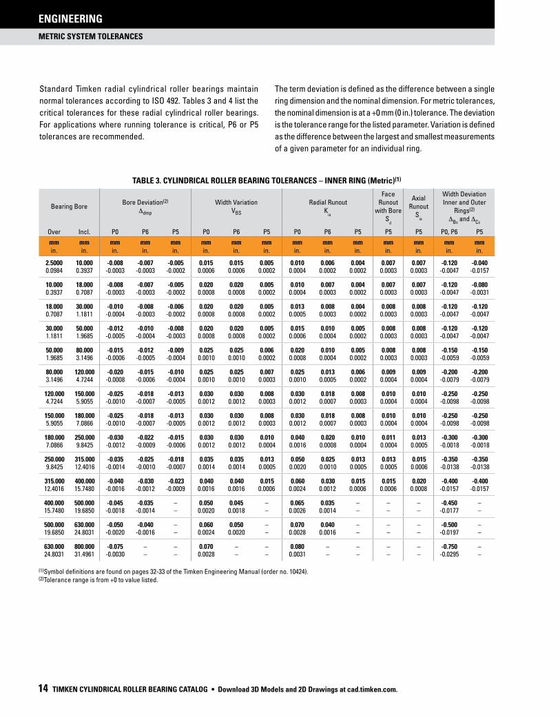
TABLE 3. CYLINDRICAL ROLLER BEARING TOLERANCES – INNER RING (Metric)(1)
Bearing BoreBore Deviation(2)
Δdmp
Width VariationVBS
Radial Runout K
ia
FaceRunout
with BoreS
d
Axial Runout
Sia
Width Deviation Inner and Outer
Rings(2)
ΔBs
and ΔCs
Over Incl. P0 P6 P5 P0 P6 P5 P0 P6 P5 P5 P5 P0, P6 P5
mmin.
mmin.
mmin.
mmin.
mmin.
mmin.
mmin.
mmin.
mmin.
mmin.
mmin.
mmin.
mmin.
mmin.
mmin.
2.5000 10.000 -0.008 -0.007 -0.005 0.015 0.015 0.005 0.010 0.006 0.004 0.007 0.007 -0.120 -0.0400.0984 0.3937 -0.0003 -0.0003 -0.0002 0.0006 0.0006 0.0002 0.0004 0.0002 0.0002 0.0003 0.0003 -0.0047 -0.0157
10.000 18.000 -0.008 -0.007 -0.005 0.020 0.020 0.005 0.010 0.007 0.004 0.007 0.007 -0.120 -0.0800.3937 0.7087 -0.0003 -0.0003 -0.0002 0.0008 0.0008 0.0002 0.0004 0.0003 0.0002 0.0003 0.0003 -0.0047 -0.0031
18.000 30.000 -0.010 -0.008 -0.006 0.020 0.020 0.005 0.013 0.008 0.004 0.008 0.008 -0.120 -0.1200.7087 1.1811 -0.0004 -0.0003 -0.0002 0.0008 0.0008 0.0002 0.0005 0.0003 0.0002 0.0003 0.0003 -0.0047 -0.0047
30.000 50.000 -0.012 -0.010 -0.008 0.020 0.020 0.005 0.015 0.010 0.005 0.008 0.008 -0.120 -0.1201.1811 1.9685 -0.0005 -0.0004 -0.0003 0.0008 0.0008 0.0002 0.0006 0.0004 0.0002 0.0003 0.0003 -0.0047 -0.0047
50.000 80.000 -0.015 -0.012 -0.009 0.025 0.025 0.006 0.020 0.010 0.005 0.008 0.008 -0.150 -0.1501.9685 3.1496 -0.0006 -0.0005 -0.0004 0.0010 0.0010 0.0002 0.0008 0.0004 0.0002 0.0003 0.0003 -0.0059 -0.0059
80.000 120.000 -0.020 -0.015 -0.010 0.025 0.025 0.007 0.025 0.013 0.006 0.009 0.009 -0.200 -0.2003.1496 4.7244 -0.0008 -0.0006 -0.0004 0.0010 0.0010 0.0003 0.0010 0.0005 0.0002 0.0004 0.0004 -0.0079 -0.0079
120.000 150.000 -0.025 -0.018 -0.013 0.030 0.030 0.008 0.030 0.018 0.008 0.010 0.010 -0.250 -0.2504.7244 5.9055 -0.0010 -0.0007 -0.0005 0.0012 0.0012 0.0003 0.0012 0.0007 0.0003 0.0004 0.0004 -0.0098 -0.0098
150.000 180.000 -0.025 -0.018 -0.013 0.030 0.030 0.008 0.030 0.018 0.008 0.010 0.010 -0.250 -0.2505.9055 7.0866 -0.0010 -0.0007 -0.0005 0.0012 0.0012 0.0003 0.0012 0.0007 0.0003 0.0004 0.0004 -0.0098 -0.0098
180.000 250.000 -0.030 -0.022 -0.015 0.030 0.030 0.010 0.040 0.020 0.010 0.011 0.013 -0.300 -0.3007.0866 9.8425 -0.0012 -0.0009 -0.0006 0.0012 0.0012 0.0004 0.0016 0.0008 0.0004 0.0004 0.0005 -0.0018 -0.0018
250.000 315.000 -0.035 -0.025 -0.018 0.035 0.035 0.013 0.050 0.025 0.013 0.013 0.015 -0.350 -0.3509.8425 12.4016 -0.0014 -0.0010 -0.0007 0.0014 0.0014 0.0005 0.0020 0.0010 0.0005 0.0005 0.0006 -0.0138 -0.0138
315.000 400.000 -0.040 -0.030 -0.023 0.040 0.040 0.015 0.060 0.030 0.015 0.015 0.020 -0.400 -0.40012.4016 15.7480 -0.0016 -0.0012 -0.0009 0.0016 0.0016 0.0006 0.0024 0.0012 0.0006 0.0006 0.0008 -0.0157 -0.0157
400.000 500.000 -0.045 -0.035 – 0.050 0.045 – 0.065 0.035 – – – -0.450 –15.7480 19.6850 -0.0018 -0.0014 – 0.0020 0.0018 – 0.0026 0.0014 – – – -0.0177 –
500.000 630.000 -0.050 -0.040 – 0.060 0.050 – 0.070 0.040 – – – -0.500 –19.6850 24.8031 -0.0020 -0.0016 – 0.0024 0.0020 – 0.0028 0.0016 – – – -0.0197 –
630.000 800.000 -0.075 – – 0.070 – – 0.080 – – – – -0.750 –24.8031 31.4961 -0.0030 – – 0.0028 – – 0.0031 – – – – -0.0295 –
(1)Symbol definitions are found on pages 32-33 of the Timken Engineering Manual (order no. 10424).(2)Tolerance range is from +0 to value listed.
Standard Timken radial cylindrical roller bearings maintain
normal tolerances according to ISO 492. Tables 3 and 4 list the
critical tolerances for these radial cylindrical roller bearings.
For applications where running tolerance is critical, P6 or P5
tolerances are recommended.
METRIC SYSTEM TOLERANCES
ENGINEERING
The term deviation is defined as the difference between a single
ring dimension and the nominal dimension. For metric tolerances,
the nominal dimension is at a +0 mm (0 in.) tolerance. The deviation
is the tolerance range for the listed parameter. Variation is defined
as the difference between the largest and smallest measurements
of a given parameter for an individual ring.
• Download 3D Models and 2D Drawings at cad.timken.com.

METRIC SYSTEM TOLERANCES
ENGINEERING
TIMKEN CYLINDRICAL ROLLER BEARING CATALOG 15
ENGINEERING
TABLE 4. CYLINDRICAL ROLLER BEARING TOLERANCES – OUTER RING (Metric)(1)
Bearing O.D.Outside Deviation(2)
ΔDmp
Width VariationV
CS
Radial RunoutK
ea
Axial Runout
Sea
Outside Diameter Runout
With FaceS
D
Over Incl. P0 P6 P5 P0 P6 P0 P6 P5 P5 P5
mmin.
mmin.
mmin.
mmin.
mmin.
mmin.
mmin.
mmin.
mmin.
mmin.
mmin.
mmin.
0.000 18.000 -0.008 -0.007 -0.005 0.015 0.005 0.015 0.008 0.005 0.008 0.0080.0000 0.7087 -0.0003 -0.0003 -0.0002 0.0006 0.0002 0.0006 0.0003 0.0002 0.0003 0.0003
18.000 30.000 -0.009 -0.008 -0.006 0.020 0.005 0.015 0.009 0.006 0.008 0.0080.7087 1.1811 -0.0004 -0.0003 -0.00024 0.0008 0.0002 0.0006 0.0004 0.00024 0.0003 0.0003
30.000 50.000 -0.011 -0.009 -0.007 0.020 0.005 0.020 0.010 0.007 0.008 0.0081.1811 1.9685 -0.0004 -0.0004 -0.0003 0.0008 0.0002 0.0008 0.0004 0.0003 0.0003 0.0003
50.000 80.000 -0.013 -0.011 -0.009 0.025 0.006 0.025 0.013 0.008 0.010 0.0081.9685 3.1496 -0.0005 -0.0004 -0.0004 0.0010 0.00024 0.0010 0.0005 0.0003 0.0004 0.0003
80.000 120.000 -0.015 -0.013 -0.010 0.025 0.008 0.035 0.018 0.010 0.011 0.0093.1496 4.7244 -0.0006 -0.0005 -0.0004 0.0010 0.0003 0.0014 0.0007 0.0004 0.0004 0.0004
120.000 150.000 -0.018 -0.015 -0.011 0.030 0.008 0.040 0.020 0.011 0.013 0.0104.7244 5.9055 -0.0007 -0.0006 -0.0004 0.0012 0.0003 0.0016 0.0008 0.0004 0.0005 0.0004
150.000 180.000 -0.025 -0.018 -0.013 0.030 0.008 0.045 0.023 0.013 0.014 0.0105.9055 7.0866 -0.0010 -0.0007 -0.0005 0.0012 0.0003 0.0018 0.0009 0.0005 0.0006 0.0004
180.000 250.000 -0.030 -0.020 -0.015 0.030 0.010 0.050 0.025 0.015 0.015 0.0117.0866 9.8425 -0.0012 -0.0008 -0.0006 0.0012 0.0004 0.0020 0.0010 0.0006 0.0006 0.0004
250.000 315.000 -0.035 -0.025 -0.018 0.035 0.011 0.060 0.030 0.018 0.018 0.0139.8425 12.4016 -0.0014 -0.0010 -0.0007 0.0014 0.0004 0.0024 0.0012 0.0007 0.0007 0.0005
315.000 400.000 -0.040 -0.028 -0.020 0.040 0.013 0.070 0.035 0.020 0.020 0.01312.4016 15.7480 -0.0016 -0.0011 -0.0008 0.0016 0.0005 0.0028 0.0014 0.0008 0.0008 0.0005
400.000 500.000 -0.045 -0.033 -0.023 0.045 0.015 0.080 0.040 0.023 0.023 0.01515.7480 19.6850 -0.0018 -0.0013 -0.0009 0.0018 0.0006 0.0031 0.0016 0.0009 0.0009 0.0006
500.000 630.000 -0.050 -0.038 -0.028 0.050 0.018 0.100 0.050 0.025 0.025 0.01819.6850 24.8031 -0.0020 -0.0015 -0.0011 0.0020 0.0007 0.0039 0.0020 0.0010 0.0010 0.0007
630.000 800.000 -0.075 -0.045 -0.035 – 0.020 0.120 0.060 0.030 0.030 0.02024.8031 31.4961 -0.0030 -0.0018 -0.0014 – 0.0008 0.0047 0.0024 0.0012 0.0012 0.0008
800.000 1000.000 -0.100 -0.060 – – – 0.140 0.075 – – –31.4961 39.3701 -0.0040 -0.0024 – – – 0.0055 0.0030 – – –
1000.000 1250.000 -0.125 – – – – 0.160 – – – –39.3701 49.2126 -0.0050 – – – – 0.0063 – – – –
(1)Symbol definitions are found on pages 32-33 of the Timken Engineering Manual (order no. 10424).(2)Tolerance range is from +0 to value listed.
Download 3D Models and 2D Drawings at cad.timken.com. •

BEARING TYPES AND CAGES
ENGINEERING
16 TIMKEN CYLINDRICAL ROLLER BEARING CATALOG
MOUNTINGCylindrical roller bearings can be mounted individually, but most
often are mounted in combination with another cylindrical roller,
a spherical roller or a tapered roller bearing.
Fig. 8 shows a pulverizer wheel assembly where a two-row
spherical roller bearing is mounted in combination with a
cylindrical roller bearing. In this application, the cylindrical roller
bearing allows the shaft to float relative to the housing.
Fig. 9 shows a single-reduction gear reducer with herringbone
gears. A tapered roller bearing is mounted in combination with a
cylindrical roller bearing on the upper shaft, and two cylindrical
bearings are mounted on the lower shaft.
FITTING PRACTICETables 6-18 on pages 22-39 list the recommended fitting practice
for cylindrical roller bearings. The tables assume:
• The bearing is of normal precision.
• The housing is thick and made from steel or cast iron.
• The shaft is solid and made from steel.
• The bearing seats are ground or accurately turned to less
than approximately 1.6 µm Ra finish.
The suggested fit symbols are in accordance with ISO 286. For
help with recommended fitting practices, contact your Timken
representative.
Fig. 8. Pulverizer wheel assembly.
Fig. 9. Single-reduction gear reducer.
CYLINDRICAL ROLLER BEARING MOUNTING, FITTING, SETTING AND INSTALLATION
MOUNTING, FITTING, SETTING AND INSTALLATION
ENGINEERING
WARNINGFailure to observe the following warnings could
create a risk of death or serious injury.
Proper maintenance and handling practices are critical. Always follow installation instructions and
maintain proper lubrication.
Never spin a bearing with compressed air. The rollers may be forcefully expelled.
• Download 3D Models and 2D Drawings at cad.timken.com.

BEARING TYPES AND CAGES
ENGINEERING
TIMKEN CYLINDRICAL ROLLER BEARING CATALOG 17
MOUNTING, FITTING, SETTING AND INSTALLATION
ENGINEERING
As a general guideline, rotating inner rings should be applied
with an interference fit. Loose fits may permit the inner rings to
creep or turn and wear the shaft and the backing shoulder. This
wear may result in excessive bearing looseness and possible
bearing and shaft damage. Additionally, abrasive metal particles
resulting from creep or turning may enter into the bearing and
cause damage and vibration.
Stationary inner-ring fitting practice depends on the loading of the
application. The load conditions and bearing envelope dimensions
should be used to select the suggested shaft fit from the tables.
Similarly, rotating outer-ring applications should use an
interference fit between the outer ring and housing.
Stationary outer rings are generally mounted with loose fits to
permit assembly and disassembly.
Thin-walled housings, light-alloy housings or hollow shafts must
use press fits tighter than required for thick-walled housings,
steel or cast iron housings or solid shafts. Tighter fits also are
required when mounting the bearing on relatively rough, or
unground surfaces.
SETTINGTo achieve appropriate operation clearance, attention must be
paid to the effects fitting practice and thermal gradients have
within the bearing.
FITTING PRACTICE
• An interference fit between the inner ring and a solid steel
shaft will reduce the radial clearance within the bearing by
approximately 85 percent of the fit.
• Interference fits between the outer ring and steel or cast iron
housing will reduce radial clearance by approximately 60
percent.
THERMAL GRADIENTS
• Thermal gradients within the bearing are primarily a func-
tion of the bearing rotational speed. As speed increases,
thermal gradients increase, thermal growth occurs and the
radial clearance is reduced.
• As a rule of thumb, radial clearance should be increased for
speeds in excess of 70 percent of the speed rating.
For help selecting the correct radial internal clearance for your
application, consult with your Timken representative.
Radial internal clearance tolerances are listed in table 5.
Cylindrical roller bearings are ordered with a specified standard
or non-standard radial internal clearance value. The standard
radial internal clearances are designated as C2, C0 (normal), C3,
C4 or C5 and are in accordance with ISO 5753. C2 represents the
minimum clearance and C5 represents the maximum clearance.
Non-standardized values also are available by special request.
The clearance required for a given application depends on the
desired operating precision, the rotational speed of the bearing,
and the fitting practice used. Most applications use a normal or
C3 clearance. Typically, larger clearance reduces the operating
load zone of the bearing, increases the maximum roller load and
reduces the bearing’s expected life. However, a cylindrical roller
bearing that has been put into a preload condition can experience
premature bearing damage caused by excessive heat generation
and/or material fatigue. As a general guideline, cylindrical roller
bearings should not operate in a preloaded condition.
Download 3D Models and 2D Drawings at cad.timken.com. •

BEARING TYPES AND CAGES
ENGINEERING
18 TIMKEN CYLINDRICAL ROLLER BEARING CATALOG
MOUNTING, FITTING, SETTING AND INSTALLATION
ENGINEERING
TABLE 5. RADIAL INTERNAL CLEARANCE LIMITS – CYLINDRICAL ROLLER BEARINGS – CYLINDRICAL BORE
Bore – RIC
Bore (Nominal) C2 C0 C3 C4 C5
Over Incl. Min. Max. Min. Max. Min. Max. Min. Max. Min. Max.
mmin.
mmin.
mmin.
mmin.
mmin.
mmin.
mmin.
mmin.
mmin.
mmin.
mmin.
mmin.
– 10 0.000 0.025 0.020 0.0045 0.035 0.060 0.050 0.075 – –– 0.3937 0.0000 0.0010 0.0008 0.0018 0.0014 0.0024 0.0020 0.0030 – –
10 24 0.000 0.025 0.020 0.0045 0.035 0.060 0.050 0.075 0.065 0.0900.3937 0.9449 0.0000 0.0010 0.0008 0.0018 0.0014 0.0024 0.0020 0.0030 0.0026 0.0035
24 30 0.000 0.025 0.020 0.0045 0.035 0.060 0.050 0.075 0.070 0.0950.9449 1.1811 0.0000 0.0010 0.0008 0.0018 0.0014 0.0024 0.0020 0.0030 0.0028 0.0037
30 40 0.005 0.030 0.025 0.050 0.0045 0.070 0.060 0.085 0.080 0.1051.1811 1.5748 0.0002 0.0012 0.0010 0.0020 0.0018 0.0028 0.0024 0.0033 0.0031 0.0041
40 50 0.005 0.035 0.030 0.060 0.050 0.080 0.070 0.100 0.095 0.1251.5748 1.9685 0.0002 0.0014 0.0012 0.0024 0.0020 0.0031 0.0028 0.0039 0.0037 0.0049
50 65 0.010 0.040 0.040 0.070 0.060 0.090 0.080 0.110 0.110 0.1401.9685 2.5591 0.0004 0.0016 0.0016 0.0028 0.0024 0.0035 0.0031 0.0043 0.0043 0.0055
65 80 0.010 0.0045 0.040 0.075 0.065 0.100 0.090 0.125 0.130 0.1652.5591 3.1496 0.0004 0.0018 0.0016 0.0030 0.0026 0.0039 0.0035 0.0049 0.0051 0.0065
80 100 0.015 0.050 0.050 0.085 0.075 0.110 0.105 0.140 0.155 0.1903.1496 3.9370 0.0006 0.0020 0.0020 0.0033 0.0030 0.0043 0.0041 0.0055 0.0061 0.0075
100 120 0.015 0.055 0.050 0.090 0.085 0.125 0.125 0.165 0.180 0.2203.9370 4.7244 0.0006 0.0022 0.0020 0.0035 0.0033 0.0049 0.0049 0.0065 0.0071 0.0087
120 140 0.015 0.060 0.060 0.105 0.100 0.145 0.145 0.190 0.200 0.2454.7244 5.5118 0.0006 0.0024 0.0024 0.0041 0.0039 0.0057 0.0057 0.0075 0.0079 0.0096
140 160 0.020 0.070 0.070 0.120 0.115 0.165 0.165 0.215 0.225 0.2755.5118 6.2992 0.0008 0.0028 0.0028 0.0047 0.0045 0.0065 0.0065 0.0085 0.0089 0.0108
160 180 0.025 0.075 0.075 0.125 0.120 0.170 0.170 0.220 0.250 0.3006.2992 7.0866 0.0010 0.0030 0.0030 0.0049 0.0047 0.0067 0.0067 0.0087 0.0098 0.0118
180 200 0.035 0.090 0.090 0.145 0.140 0.195 0.195 0.250 0.275 0.3307.0866 7.8740 0.0014 0.0035 0.0035 0.0057 0.0055 0.0077 0.0077 0.0098 0.0108 0.0130
200 225 0.045 0.105 0.105 0.165 0.160 0.220 0.220 0.280 0.305 0.3657.8740 8.8583 0.0018 0.0041 0.0041 0.0065 0.0063 0.0087 0.0087 0.0110 0.0120 0.0144
225 250 0.045 0.110 0.110 0.175 0.170 0.235 0.235 0.300 0.330 0.3958.8583 9.8425 0.0018 0.0043 0.0043 0.0069 0.0067 0.0093 0.0093 0.0118 0.0130 0.0156
250 280 0.055 0.125 0.125 0.195 0.190 0.260 0.260 0.330 0.370 0.4409.8425 11.0236 0.0022 0.0049 0.0049 0.0077 0.0075 0.0102 0.0102 0.0130 0.0146 0.0173
280 315 0.055 0.130 0.130 0.205 0.200 0.275 0.275 0.350 0.410 0.48511.0236 12.4016 0.0022 0.0051 0.0051 0.0081 0.0079 0.0108 0.0108 0.0138 0.0161 0.0191
315 355 0.065 0.145 0.145 0.225 0.225 0.305 0.305 0.385 0.455 0.53512.4016 13.9764 0.0026 0.0057 0.0057 0.0089 0.0089 0.0120 0.0120 0.0152 0.0179 0.0211
355 400 0.100 0.190 0.190 0.280 0.280 0.370 0.370 0.460 0.510 0.60013.9764 15.7480 0.0039 0.0075 0.0075 0.0110 0.0110 0.0146 0.0146 0.0181 0.0201 0.0236
400 450 0.110 0.210 0.210 0.310 0.310 0.410 0.410 0.510 0.565 0.66515.7480 17.7165 0.0043 0.0083 0.0083 0.0122 0.0122 0.0161 0.0161 0.0201 0.0222 0.0262
450 500 0.110 0.220 0.220 0.330 0.330 0.440 0.440 0.550 0.625 0.73517.7165 19.6850 0.0043 0.0087 0.0087 0.0130 0.0130 0.0173 0.0173 0.0217 0.0246 0.0289
500 560 0.120 0.240 0.240 0.360 0.360 0.480 0.480 0.600 0.690 0.81019.6850 22.0472 0.0047 0.0095 0.0095 0.0142 0.0142 0.0189 0.0189 0.0236 0.0272 0.0319
560 630 0.140 0.260 0.260 0.380 0.380 0.500 0.500 0.620 0.780 0.90022.0472 24.8031 0.0055 0.0102 0.0102 0.0150 0.0150 0.0197 0.0197 0.0244 0.0307 0.0354
630 710 0.145 0.285 0.285 0.425 0.425 0.565 0.565 0.705 0.865 1.00524.8031 27.9528 0.0057 0.0112 0.0112 0.0167 0.0167 0.0222 0.0222 0.0278 0.0341 0.0396
710 800 0.150 0.310 0.310 0.470 0.470 0.630 0.630 0.790 0.975 1.13527.9528 31.4961 0.0059 0.0122 0.0122 0.0185 0.0185 0.0248 0.0248 0.0311 0.0384 0.0447
800 900 0.180 0.350 0.350 0.520 0.520 0.690 0.690 0.860 1.095 1.26531.4961 35.4331 0.0071 0.0138 0.0138 0.0205 0.0205 0.0272 0.0272 0.0339 0.0431 0.0498
900 1000 0.200 0.390 0.390 0.580 0.580 0.770 0.770 0.960 1.215 1.40535.4331 39.3701 0.0079 0.0154 0.0154 0.0228 0.0228 0.0303 0.0303 0.0378 0.0478 0.0553
• Download 3D Models and 2D Drawings at cad.timken.com.

BEARING TYPES AND CAGES
ENGINEERING
TIMKEN CYLINDRICAL ROLLER BEARING CATALOG 19
MOUNTING, FITTING, SETTING AND INSTALLATION
ENGINEERING
Shaft fit RIC reductions and clearance:
For a 150 mm nominal bore at C3, the RIC will be 0.115 to 0.165
mm (0.0045 to 0.0065 in.). Recalculating shaft fit RIC reduction
and clearance:
max. clearance = max. RIC - min. fit reduction
= 0.165 - 0.034 = 0.131 mm (0.0052 in.)
min. clearance = min. RIC - max. fit reduction
= 0.115 - 0.074 = 0.041 mm (0.0016 in.)
Since the minimum mounted clearance is less than the minimum
suggested RIC of 0.056 mm (0.0022 in.), the C3 RIC clearance limit
needs to be reevaluated.
Download 3D Models and 2D Drawings at cad.timken.com. •

MOUNTING, FITTING, SETTING AND INSTALLATION
ENGINEERING
20 TIMKEN CYLINDRICAL ROLLER BEARING CATALOG
INSTALLATION
When using a tight-fit inner ring, the method of assembly will
depend on whether the bearing has a cylindrical or tapered bore.
Mounting cylindrical bore bearings
Heat expansion method
• Most applications require a tight interference fit on the shaft.
• Mounting is simplified by heating the bearing to expand it
sufficiently to slide easily onto the shaft.
• Two methods of heating are commonly used:
- Tank of heated oil.
- Induction heating.
• The first is accomplished by heating the bearing in a tank of
oil that has a high flash point.
• The oil temperature should not be allowed to exceed 121° C
(250° F). A temperature of 93° C (200° F) is sufficient for most
applications.
• The bearing should be heated for 20 or 30 minutes, or until it
is expanded sufficiently to slide onto the shaft easily.
• The induction heating process can be used for mounting
bearings.
• Induction heating is rapid. Care must be taken to prevent
bearing temperature from exceeding 93° C (200° F).
• Trial runs with the unit and bearing are usually necessary to
obtain proper timing.
• Thermal crayons melted at predetermined temperatures
can be used to check the bearing temperature.
• While the bearing is hot, it should be positioned squarely
against the shoulder.
• Lockwashers and locknuts or clamping plates are then
installed to hold the bearing against the shoulder of the shaft.
• As the bearing cools, the locknut or clamping plate should
be tightened.
• In cases of outer ring rotation, where the outer ring is
a tight fit in the housing, the housing member can be
expanded by heating.
• The oil bath is shown in fig. 10. The bearing should not be in
direct contact with the heat source.
• The usual arrangement is to have a screen several inches
from the bottom of the tank. Small support blocks separate
the bearing from the screen.
• It is important to keep the bearing away from any
localized high-heat source that may raise its temperature
excessively, resulting in ring hardness reduction.
• Flame-type burners are commonly used. An automatic
device for temperature control is desirable.
• If safety regulations prevent the use of an open heated oil
bath, a mixture of 15 percent soluble-oil water may be used.
This mixture may be heated to a maximum of 93° C (200° F)
without being flammable.
OIL
BEARING SUPPORT
BLOCK
FLAME BURNER
BEARING
BEARING HELD
FROM BOTTOM
BY SCREEN
Fig. 10. Heat expansion method.
Remove oil or rust inhibitor from parts before heating, to avoid fire and fumes.
CAUTIONFailure to observe the following warnings could
create a risk of death or serious injury.
NOTE
Never use steam or hot water when cleaning the bearings because these methods can create rust or corrosion.
NOTE
Never expose any surface of a bearing to the flame of a torch.
NOTE
Do not heat bearing beyond 149˚ C (300˚ F).
• Download 3D Models and 2D Drawings at cad.timken.com.

MOUNTING, FITTING, SETTING AND INSTALLATION
ENGINEERING
TIMKEN CYLINDRICAL ROLLER BEARING CATALOG 21
Arbor press method
• An alternate method of mounting, generally used only on
smaller size bearings, is to press the bearing onto the shaft
or into the housing. This can be done by using an arbor
press and a mounting tube as shown in fig. 11.
• The tube should be made from soft steel with an inside
diameter slightly larger than the shaft.
• The O.D. of the tube should not exceed the shaft backing
diameter given in the Timken® Spherical Roller Bearing
Catalog (order no. 10446), found on timken.com/catalogs.
• The tube should be faced square at both ends. It should be
thoroughly clean inside and out, and long enough to clear
the end of the shaft after the bearing is mounted.
• If the outer ring is being pressed into the housing, the O.D.
of the mounting tube should be slightly smaller than the
housing bore. The I.D. should not be less than the suggested
housing backing diameter in the table of dimensions
available in the Timken Spherical Roller Bearing Catalog
(order no. 10446), found on timken.com/catalogs.
• Coat the shaft with a light machine oil to reduce the force
needed for a press fit.
• Carefully place the bearing on the shaft, making sure it is
square with the shaft axis.
• Apply steady pressure from the arbor ram to drive the
bearing firmly against the shoulder.
NOTE
Never attempt a press fit on a shaft by applying pressure to the outer ring or a press fit in a housing by applying
pressure to the inner ring.
Fig. 11. Arbor press method.
Download 3D Models and 2D Drawings at cad.timken.com. •

SHAFT AND HOUSING FITS
ENGINEERING
22 TIMKEN CYLINDRICAL ROLLER BEARING CATALOG
SHAFT AND HOUSING FITS
TABLE 6. CYLINDRICAL ROLLER BEARINGS SHAFT FITS (EXCEPT 5200 SERIES AND FOUR-ROW CYLINDRICALS)
Load Limit Shaft Diameter Shaft Tolerance
Lower Uppermm in.
mm in.
Symbol(1)
INNER RING STATIONARY
0 C(2) All All g6
0 C All All h6
INNER RING ROTATION OR INDETERMINATE
Over Incl.
0 0.08C
0 0
40 1.57
140 5.51
320 12.60
500 19.68
40 1.57
140 5.51
320 12.60
500 19.68
– –
k6(3)
m6(4)
n6
p6
–
0.08C 0.18C
0 0
40 1.57
100 3.94
140 5.51
320 12.60
500 19.68
40 1.57
100 3.94
140 5.51
320 12.60
500 19.68
– –
k5
m5
m6
n6
p6
r6
0.18C C
0 0
40 1.57
65 2.56
140 5.51
320 12.60
500 19.68
40 1.57
65 2.56
140 5.51
320 12.60
500 19.68
– –
m5(5)
m6(5)
n6(5)
p6(5)
r6(5)
r7(5)
THRUST LOADS
Not suggested, consult your Timken engineer.
(1)For solid shaft. See pages 24-29 for tolerance values.(2)C = dynamic load rating. (3)Use k5 for high-precision applications. (4)Use m5 for high-precision applications.(5)Bearings with greater than nominal clearance must be used.
CYLINDRICAL ROLLER BEARINGS
TABLE 7. FOUR-ROW CYLINDRICAL ROLLER BEARING SHAFTS
Load Limit Shaft Diameter Shaft Tolerance
Lower Uppermm in.
mm in.
Symbol(1)
All
100 120 n63.93 4.72
120 225 p64.72 8.85
225 400 r68.85 15.75
400 s615.75
(1)For solid shaft. See pages 24-29 for tolerance values.
• Download 3D Models and 2D Drawings at cad.timken.com.

SHAFT AND HOUSING FITS
ENGINEERING
TIMKEN CYLINDRICAL ROLLER BEARING CATALOG 23
TABLE 8. CYLINDRICAL ROLLER BEARING HOUSING FITS
Operating Conditions ExamplesHousing
Tolerance Symbol (1)
Outer RingDisplaceable Axially
OUTER RING ROTATING
Heavy loads with thin-walled housingCrane support wheelsWheel hubs (roller bearings)Crank bearings
P6 No
Normal to heavy loadsWheel hubs (ball bearings)Crank bearings
N6 No
Light loadsConveyor rollersRope sheavesTension pulleys
M6 No
INDETERMINATE LOAD DIRECTION
Heavy shock loads Electric traction motors M7 No
Normal to heavy loads, axial displace-ment of outer ring not required.
Electric motorsPumpsCrankshaft main bearings
K6No, normally
Below this line, housing can either be one piece or split. Above this line, a split housing is not suggested.
Light to normal loads, axial displacementof outer ring desired.
Electric motorsPumpsCrankshaft main bearings
J6 Yes, normally
OUTER RING STATIONARY
Shock loads, temporary complete unloading
Heavy rail vehicles J6 Yes, normally
AllOne-piece housing
General applicationsHeavy rail vehicles
H6 Easily
Radially split housing Transmission drives H7 Easily
Heat supplied through shaft Dryer cylinders G7 Easily
(1)Cast iron steel housing. See pages 30-37 for numerical values. Where wider tolerances are permissible, P7, N7, M7, K7, J7 and H7 values may be used in place of P6, N6, M6, K6,
J6 and H6 values, respectively.
Download 3D Models and 2D Drawings at cad.timken.com. •

SHAFT AND HOUSING FITS
These charts are guidelines for specifying shaft and housing fits related to particular operating conditions. Please contact your Timken engineer for more information.
ENGINEERING
24 TIMKEN CYLINDRICAL ROLLER BEARING CATALOG
TABLE 9. RADIAL BALL, SPHERICAL AND CYLINDRICAL ROLLER BEARING SHAFT TOLERANCES
Bearing Bore g6 h6 h5 j5
Nominal (Max.)Tolerance(1)
Shaft DiameterFit
Shaft DiameterFit
Shaft DiameterFit
Shaft DiameterFit
Over Incl. Max. Min. Max. Min. Max. Min. Max. Min.
mmin.
mmin.
mmin.
mmin.
mmin.
mmin.
mmin.
mmin.
mmin.
mmin.
mmin.
mmin.
mmin.
mmin.
mmin.
0.012L 0.008L 0.005L 0.002L3.000 6.000 -0.008 -0.004 -0.012 0.004T 0.000 -0.008 0.008T 0.000 -0.005 0.008T +0.003 -0.002 0.011T0.1181 0.2362 -0.003 -0.0002 -0.0005 0.0005L 0.0000 -0.003 0.0003L 0.0000 -0.0002 0.0002L +0.0001 -0.0001 0.0001L
0.0001T 0.0003T 0.0003T 0.0004T
0.014L 0.009L 0.006L 0.002L6.000 10.000 -0.008 -0.005 -0.014 0.003T 0.000 -0.009 0.008T 0.000 -0.006 0.008T +0.004 -0.002 0.012T0.2362 0.3937 -0.003 -0.0002 -0.0006 0.0006L 0.0000 -0.0004 0.0004L 0.0000 -0.0002 0.0002L +0.0002 -0.0001 0.0001L
0.0001T 0.0003T 0.0003T -0.0005T
0.017L 0.011L 0.008L 0.003L10.000 18.000 -0.008 -0.006 -0.017 0.002T 0.000 -0.011 0.008T 0.000 -0.008 0.008T +0.005 -0.003 0.013T0.3937 0.7087 -0.003 -0.0002 -0.0007 0.0007L 0.0000 -0.0004 0.0004L 0.0000 -0.0003 0.0003L +0.0002 -0.0001 0.0001L
-0.0001T 0.0003T 0.0003T 0.0005T
0.020L 0.013L
– – –
0.004L18.000 30.000 -0.010 -0.007 -0.020 0.003T 0.000 -0.013 0.010T +0.005 -0.004 0.015T0.7087 1.1811 -0.0004 -0.0003 -0.0008 0.0008L 0.0000 -0.0005 0.0005L +0.0002 -0.0002 0.0002L
0.0001T 0.0004T 0.0006T
0.025L 0.016L
– – –
0.005L30.000 50.000 -0.012 -0.009 -0.025 0.003T 0.000 -0.016 0.012T +0.006 -0.005 0.018T1.1811 1.9685 -0.0005 -0.0004 -0.0010 0.0010L 0.0000 -0.0006 0.0006L +0.0002 -0.0002 0.0002L
0.0001T 0.0005T 0.0007T
0.029L 0.019L
– – –
0.007L50.000 80.000 -0.015 -0.010 -0.029 0.005T 0.000 -0.019 0.015T +0.006 -0.007 0.021T1.9685 3.1496 -0.0006 -0.0004 -0.0011 0.0011L 0.0000 -0.0007 0.0007L +0.0002 -0.0003 0.0003L
0.0002T 0.0006T 0.0008T
0.034L 0.022L
– – –
0.009L80.000 120.000 -0.020 -0.012 -0.034 0.008T 0.000 -0.022 0.020T +0.006 -0.009 0.026T3.1496 4.7244 -0.0008 -0.0005 -0.0013 0.0013L 0.0000 -0.0009 0.0009L +0.0002 -0.0004 0.0004L
0.0003T 0.0008T 0.0010T
0.039L 0.025L
– – –
0.011L120.000 180.000 -0.025 -0.014 -0.039 0.011T 0.000 -0.025 0.025T +0.007 -0.011 0.032T4.7244 7.0866 -0.0010 -0.0006 -0.0015 0.0015L 0.0000 -0.0010 0.0010L +0.0003 -0.0004 0.0004L
0.0004T 0.0010T 0.0013T
0.044T 0.029L
– – –
0.013L180.000 200.000 -0.030 -0.015 -0.044 0.015T 0.000 -0.029 0.030T +0.007 -0.013 0.037T7.0866 7.8740 -0.0012 -0.0006 -0.0017 0.0017L 0.0000 -0.0011 0.0011L +0.0003 -0.0005 0.0005L
0.0006T 0.0012T 0.0015T
0.044T 0.029L
– – –
0.013L200.000 225.000 -0.030 -0.015 -0.044 0.015T 0.000 -0.029 0.030T +0.007 -0.013 0.037T7.8740 8.8583 -0.0012 -0.0006 -0.0017 0.0017L 0.0000 -0.0011 0.0011L +0.0003 -0.0005 0.0005L
0.0006T 0.0012T 0.0015T
0.044T 0.029L
– – –
0.013L225.000 250.000 -0.030 -0.015 -0.044 0.015T 0.000 -0.029 0.030T +0.007 -0.013 0.037T8.8583 9.8425 -0.0012 -0.0006 -0.0017 0.0017L 0.0000 -0.0011 0.0011L +0.0003 -0.0005 0.0005L
0.0006T 0.0012T 0.0015T
0.049L 0.032L
– – –
0.016L250.000 280.000 -0.035 -0.017 -0.049 0.018T 0.000 -0.032 0.035T +0.007 -0.016 0.042T9.8425 11.0236 -0.0014 -0.0007 -0.0019 0.0019L 0.0000 -0.0013 0.0013L +0.0003 -0.0006 0.0006L
0.0007T 0.0014T 0.0017T
0.049L 0.032L
– – –
0.016L280.000 315.000 -0.035 -0.017 -0.049 0.018T 0.000 -0.032 0.035T +0.007 -0.016 0.042T11.0236 12.4016 -0.0014 -0.0007 -0.0019 0.0019L 0.0000 -0.0013 0.0013L +0.0003 -0.0006 0.0006L
0.0007T 0.0014T 0.0017T
NOTE: Tolerance and shaft diameters are shown in the table as variances from nominal bearing bore. (1)Tolerance range is from +0 to value listed.
RADIAL BALL, SPHERICAL ROLLER AND CYLINDRICAL ROLLER BEARINGS
SHAFT TOLERANCES
• Download 3D Models and 2D Drawings at cad.timken.com.

SHAFT AND HOUSING FITS
These charts are guidelines for specifying shaft and housing fits related to particular operating conditions. Please contact your Timken engineer for more information.
ENGINEERING
TIMKEN CYLINDRICAL ROLLER BEARING CATALOG 25
j6 k5 k6 m5
Shaft DiameterFit
Shaft DiameterFit
Shaft DiameterFit
Shaft DiameterFit
Max. Min. Max. Min. Max. Min. Max. Min.
mmin.
mmin.
mmin.
mmin.
mmin.
mmin.
mmin.
mmin.
mmin.
mmin.
mmin.
mmin.
0.002L 0.001T
– – –
0.004T+0.006 -0.002 0.014T +0.006 +0.001 0.014T +0.009 +0.004 0.017T
+0.0002 -0.0001 0.0001L +0.0002 +0.0000 0.0000T +0.0004 +0.0002 0.0002T0.0005T 0.0005T 0.0007T
0.002L 0.001T
– – –
0.006T+0.007 -0.002 0.015T +0.007 +0.001 0.015T +0.012 +0.006 0.020T
+0.0003 -0.0001 0.0001L +0.0003 +0.0000 0.0000T +0.0005 +0.0002 0.0002T-0.0005T 0.0006T 0.0006T 0.0008T
0.003L 0.001T
– – –
0.007T+0.008 -0.003 0.016T +0.009 +0.001 0.017T +0.015 +0.007 0.023T
+0.0003 -0.0001 0.0001L +0.0004 +0.0000 0.0000T +0.0006 +0.0003 0.0003T0.0006T 0.0007T 0.0009T
0.004L 0.002T
– – –
0.008T+0.009 -0.004 0.019T +0.011 +0.002 0.021T +0.017 +0.008 0.027T
+0.0004 -0.0002 0.0002L +0.0004 +0.0001 0.0001T +0.0007 +0.0003 0.0003T0.0008T 0.0008T 0.0011T
0.005L 0.002T 0.002T 0.009T+0.011 -0.005 0.023T +0.013 +0.002 0.025T +0.018 +0.002 0.030T +0.020 +0.009 0.032T
+0.0004 -0.0002 0.0002L +0.0005 +0.0001 0.0001T +0.0007 +0.0001 0.0001T +0.0008 +0.0004 0.0004T0.00085T 0.0010T 0.0012T 0.00125T
0.007L 0.002T 0.002T 0.011T+0.012 -0.007 0.027T +0.015 +0.002 0.030T +0.021 +0.002 0.036T +0.024 +0.011 0.039T
+0.0005 -0.0003 0.0003L +0.0006 +0.0001 0.0001T +0.0008 +0.0001 0.0001T +0.0009 +0.0004 0.0004T
0.0011T 0.0012T 0.0014T 0.0015T
0.009L 0.003T 0.003T 0.013T+0.013 -0.009 0.033T +0.018 +0.003 0.038T +0.025 +0.003 0.045T +0.028 +0.013 0.048T
+0.0005 -0.0004 0.0004L +0.0007 +0.0001 0.0001T +0.0010 +0.0001 0.0001T +0.0011 +0.0005 0.0005T0.0013T 0.0015T 0.0018T 0.0019T
0.011L 0.003T 0.003T 0.015T+0.014 -0.011 0.039T +0.021 +0.003 0.046T +0.028 +0.003 0.053T +0.033 +0.015 0.058T
+0.0006 -0.0004 0.0004L +0.0008 +0.0001 0.0001T +0.0011 +0.0001 0.0001T +0.0013 +0.0006 0.0006T0.0016T 0.0018T 0.0021T 0.0023T
0.013L 0.004T
– – –
0.017T+0.016 -0.013 0.046T +0.024 +0.004 0.054T +0.037 +0.017 0.067T
+0.0006 -0.0005 0.0005L +0.0009 +0.0002 0.0002T +0.0015 +0.0007 0.0007T0.0018T 0.0021T 0.0027T
0.013L 0.004T
– – –
0.017T+0.016 -0.013 0.046T +0.024 +0.004 0.054T +0.037 +0.017 0.067T
+0.0006 -0.0005 0.0005L +0.0009 +0.0002 0.0002T +0.0015 +0.0007 0.0007T0.0018T 0.0021T 0.0027T
0.013L 0.004T
– – –
0.017T+0.016 -0.013 0.046T +0.024 +0.004 0.054T +0.037 +0.017 0.067T
+0.0006 -0.0005 0.0005L +0.0009 +0.0002 0.0002T +0.0015 +0.0007 0.0007T
0.0018T 0.0021T 0.0027T
0.016L 0.004T
– – –
0.020T+0.016 -0.016 0.051T +0.027 +0.004 0.062T +0.043 +0.020 0.078T
+0.0006 -0.0006 0.0006L +0.0011 +0.0002 0.0002T +0.0017 +0.0008 0.0008T0.0020T 0.0025T 0.0031T
0.016L 0.004T
– – –
0.020T+0.016 -0.016 0.051T +0.027 +0.004 0.062T +0.043 +0.020 0.078T
+0.0006 -0.0006 0.0006L +0.0011 +0.0002 0.0002T +0.0017 +0.0008 0.0008T0.0020T 0.0025T 0.0031T
Continued on next page.
Download 3D Models and 2D Drawings at cad.timken.com. •

SHAFT AND HOUSING FITS
These charts are guidelines for specifying shaft and housing fits related to particular operating conditions. Please contact your Timken engineer for more information.
ENGINEERING
26 TIMKEN CYLINDRICAL ROLLER BEARING CATALOG
TABLE 9. RADIAL BALL, SPHERICAL AND CYLINDRICAL ROLLER BEARING SHAFT TOLERANCES
Bearing Bore g6 h6 h5 j5
Nominal (Max.)Tolerance(1)
Shaft DiameterFit
Shaft DiameterFit
Shaft DiameterFit
Shaft DiameterFit
Over Incl. Max. Min. Max. Min. Max. Min. Max. Min.
mmin.
mmin.
mmin.
mmin.
mmin.
mmin.
mmin.
mmin.
mmin.
mmin.
mmin.
mmin.
mmin.
mmin.
mmin.
0.054L 0.036L
– – –
0.018L315.000 355.000 -0.040 -0.018 -0.054 0.022T 0.000 -0.036 0.040T +0.007 -0.018 0.047T12.4016 13.9764 -0.0016 -0.0007 -0.0021 0.0021L 0.0000 -0.0014 0.0014L +0.0003 -0.0007 0.0007L
0.0009T 0.0016T 0.0019T
0.054L 0.036L
– – –
0.018L355.000 400.000 -0.040 -0.018 -0.054 0.022T 0.000 -0.036 0.040T +0.007 -0.018 0.047T13.9764 15.7480 -0.0016 -0.0007 -0.0021 0.0021L 0.0000 -0.0014 0.0014L +0.0003 -0.0007 0.0007L
0.0009T 0.0016T 0.0019T
0.060L 0.040L
– – –
0.020L400.000 450.000 -0.045 -0.020 -0.060 0.025T 0.000 -0.040 0.045T +0.007 -0.020 0.052T15.7480 17.7165 -0.0018 -0.0008 -0.0024 0.0024L 0.0000 -0.0016 0.0016L +0.0003 -0.0008 0.0008L
0.0010T 0.0018T 0.0021T
0.060L 0.040L
– – –
0.020L450.000 500.000 -0.045 -0.020 -0.060 0.025T 0.000 -0.040 0.045T +0.007 -0.020 0.052T17.7165 19.6850 -0.0018 -0.0008 -0.0024 0.0024L 0.0000 -0.0016 0.0016L +0.0003 -0.0008 0.0008L
0.0010T 0.0018T 0.0020T
0.066L 0.044L
– – –
0.022L500.000 560.000 -0.050 -0.022 -0.066 0.028T 0.000 -0.044 0.050T +0.008 -0.022 0.058T19.6850 22.0472 -0.0020 -0.0009 -0.0026 0.0026L 0.0000 -0.0017 0.0017L 0.0003 -0.0009 0.0009L
0.0011T 0.0020T 0.0023T
0.066L 0.044L
– – –
0.022L560.000 630.000 -0.050 -0.022 -0.066 0.028T 0.000 -0.044 0.050T +0.008 -0.022 0.058T22.0472 24.8032 -0.0020 -0.0009 -0.0026 0.0026L 0.0000 -0.0017 0.0017L +0.0003 -0.0009 0.0009L
0.0011T 0.0020T 0.0023T
0.074L 0.050L
– – –
0.025L630.000 710.000 -0.075 -0.024 -0.074 0.051T 0.000 -0.050 0.075T +0.010 -0.025 0.085T24.8032 27.9528 -0.0030 -0.0009 -0.0029 0.0029L 0.0000 -0.0020 0.0020L +0.0004 -0.0010 0.0010L
0.0021T 0.0030T 0.0035T
0.074L 0.050L
– – –
0.025L710.000 800.000 -0.075 -0.024 -0.074 0.051T 0.000 -0.050 0.075T +0.010 -0.025 0.085T27.9528 31.4961 -0.0030 -0.0009 -0.0029 0.0029L 0.0000 -0.0020 0.0020L +0.0004 -0.0010 0.0010L
0.0021T 0.0030T 0.0035T
0.082L 0.056L
– – –
0.028L800.000 900.000 -0.100 -0.026 -0.082 0.074T 0.000 -0.056 0.100T +0.012 -0.028 0.112T31.4961 35.4331 -0.0039 -0.0010 0.0032 0.0032L 0.0000 -0.0022 0.0022L +0.0005 -0.0011 0.0011L
0.0029T 0.0039T 0.0044T
0.082L 0.056L
– – –
0.028L900.000 1000.000 -0.100 -0.026 -0.082 0.074T 0.000 -0.056 0.100T +0.012 -0.028 0.112T35.4331 39.3701 -0.0039 -0.0010 0.0032 0.0032L 0.0000 -0.0022 0.0022L +0.0005 -0.0011 0.0011L
0.0029T 0.0039T 0.0044T
0.094L 0.066L
– – –
0.033L1000.000 1120.000 -0.125 -0.028 -0.094 0.097T 0.000 -0.066 0.125T +0.013 -0.033 0.138T39.3701 44.0945 -0.0049 -0.0011 -0.0037 0.0037L 0.0000 -0.0026 0.0022L +0.0005 -0.0013 0.0013L
0.0038T 0.0039T 0.0054T
0.094L 0.066L
– – –
0.033L1120.000 1250.000 -0.125 -0.028 -0.094 0.097T 0.000 -0.066 0.125T +0.013 -0.033 0.138T44.0945 49.2126 -0.0049 -0.0011 -0.0037 0.0037L 0.0000 -0.0026 0.0022L +0.0005 -0.0013 0.0013L
0.0038T 0.0039T 0.0054T
NOTE: Tolerance and shaft diameters are shown in the table as variances from nominal bearing bore. (1)Tolerance range is from +0 to value listed.
Table 9 continued.
• Download 3D Models and 2D Drawings at cad.timken.com.

SHAFT AND HOUSING FITS
These charts are guidelines for specifying shaft and housing fits related to particular operating conditions. Please contact your Timken engineer for more information.
ENGINEERING
TIMKEN CYLINDRICAL ROLLER BEARING CATALOG 27
j6 k5 k6 m5
Shaft DiameterFit
Shaft DiameterFit
Shaft DiameterFit
Shaft DiameterFit
Max. Min. Max. Min. Max. Min. Max. Min.
mmin.
mmin.
mmin.
mmin.
mmin.
mmin.
mmin.
mmin.
mmin.
mmin.
mmin.
mmin.
0.018L 0.004T
– – –
0.021T+0.018 -0.018 0.058T +0.029 +0.046 0.069T +0.046 +0.021 0.086T+0.0007 -0.0007 0.0007L +0.0011 +0.0002 0.0002T +0.0018 +0.0008 0.0008T
0.0023T 0.0027T 0.0034T
0.018L 0.004T
– – –
0.021T+0.018 -0.018 0.058T +0.029 +0.004 0.069T +0.046 +0.021 0.086T+0.0007 -0.0007 0.0007L +0.0011 +0.0002 0.0002T +0.0018 +0.0008 0.0008T
0.0023T 0.0027T 0.0034T
0.020L 0.005T
– – –
0.023T+0.020 -0.020 0.065T +0.032 +0.005 0.077T +0.050 +0.023 0.095T+0.0008 -0.0008 0.0008L +0.0013 +0.0002 0.0002T +0.0020 +0.0009 0.0009T
0.0026T 0.0031T 0.0037T
0.020L 0.005T
– – –
0.023T+0.020 -0.020 0.065T +0.032 +0.005 0.077T +0.050 +0.023 0.095T+0.0008 -0.0008 0.0008L +0.0013 +0.0002 0.0002T +0.0020 +0.0009 0.0009T
0.0026T 0.0031T 0.0037T
0.022L 0.00T
– – –
0.026T+0.022 -0.022 0.072T +0.030 0.000 0.080T +0.056 +0.026 0.106T+0.0009 -0.0009 0.0009L +0.0012 0.0000 0.0000T +0.0022 +0.0010 0.0010T
0.0029T 0.0032T 0.0042T
0.022L 0.00T
– – –
0.026T+0.022 -0.022 0.072T +0.030 0.000 0.080T +0.056 +0.026 0.106T+0.0009 -0.0009 0.0009L +0.0012 0.0000 0.0000T +0.0022 +0.0010 0.0010T
0.0029T 0.0032T 0.0042T
0.025L 0.000T
– – –
0.030T+0.025 -0.025 0.100T +0.035 0.000 0.110T +0.065 +0.030 0.140T+0.0010 -0.0010 0.0010L +0.0014 0.0000 0.0000T +0.0026 +0.0012 0.0012T
0.0040T 0.0044T 0.0056T
0.025L 0.000T
– – –
0.030T+0.025 -0.025 0.100T +0.035 0.000 0.110T +0.065 +0.030 0.140T+0.0010 -0.0010 0.0010L +0.0014 0.0000 0.0000T +0.0026 +0.0012 0.0012T
0.0040T 0.0044T 0.0056T
0.028L 0.000T
– – –
0.034T+0.025 -0.025 0.128T +0.040 0.000 0.140T +0.074 +0.0030 0.174T+0.0010 -0.0010 0.0011L +0.0016 0.0000 0.0000T +0.0029 +0.0012 0.0012T
0.0050L 0.0055T 0.0056T
0.028L 0.000T
– – –
0.034T1000.000 +0.028 -0.028 0.128T +0.040 0.000 0.140T +0.074 +0.034 0.174T
+0.0011 -0.0011 0.0011L +0.0016 0.0000 0.0000T +0.0029 +0.0013 0.0013T0.0050T 0.0055T 0.0068T
0.033L 0.000T
– – –
0.040T1000.000 1120.000 +0.028 -0.028 0.158T +0.046 0.000 0.171T +0.086 +0.040 0.211T
+0.0011 -0.0011 0.0013L +0.0018 0.0000 0.0000T +0.0034 +0.0016 0.0016T0.0062T 0.0067T 0.0083T
0.033L 0.000T
– – –
0.040T1120.000 1250.000 +0.033 -0.033 0.158T +0.046 0.000 0.171T +0.086 +0.040 0.211T
+0.0013 -0.0013 0.0013L +0.0018 0.0000 0.0000T +0.0034 +0.0016 0.0016T0.0062T 0.0067T 0.0083T
Download 3D Models and 2D Drawings at cad.timken.com. •

SHAFT AND HOUSING FITS
These charts are guidelines for specifying shaft and housing fits related to particular operating conditions. Please contact your Timken engineer for more information.
ENGINEERING
28 TIMKEN CYLINDRICAL ROLLER BEARING CATALOG
TABLE 10. RADIAL BALL, SPHERICAL ROLLER AND CYLINDRICAL ROLLER BEARING SHAFT TOLERANCES
Bearing Bore m6 n6 p6 r6 r7
Nominal (Max.)Tolerance(1)
Shaft DiameterFit
Shaft DiameterFit
Shaft DiameterFit
Shaft DiameterFit
Shaft DiameterFit
Over Incl. Max. Min. Max. Min. Max. Min. Max. Min. Max. Min.
mmin.
mmin.
mmin.
mmin.
mmin.
mmin.
mmin.
mmin.
mmin.
mmin.
mmin.
mmin.
mmin.
mmin.
mmin.
mmin.
mmin.
mmin.
– – – – – – – – – – – – – – –3.000 6.000 -0.0080.1181 0.2362 -0.0003
– – – – – – – – – – – – – – –6.000 10.000 -0.0080.2362 0.3937 -0.0003
– – – – – – – – – – – – – – –10.000 18.000 -0.0080.3937 0.7087 -0.0003
– – – – – – – – – – – – – – –18.000 30.000 -0.0100.7087 1.1811 -0.0004
0.009T
– – – – – – – – – – – –30.000 50.000 -0.012 +0.025 +0.009 0.037T1.1811 1.9685 -0.0005 +0.0010 +0.0004 0.0004T
0.0145T
0.011T 0.020T
– – – – – – – – –50.000 80.000 -0.015 +0.030 +0.011 0.045T +0.039 +0.020 0.054T1.9685 3.1496 -0.0006 +0.0012 +0.0004 0.0004T +0.0015 +0.0008 0.0008T
0.0018T 0.0021T
0.013T 0.023T 0.037T
– – – – – –80.000 120.000 -0.020 +0.035 +0.013 0.055T +0.045 +0.023 0.065T +0.059 +0.037 0.079T3.1496 4.7244 -0.0008 +0.0014 +0.0005 0.0005T +0.0018 +0.0009 0.0009T +0.0023 +0.0015 0.0015T
0.0022T 0.0026T 0.0031T
0.015T 0.027T 0.043T 0.065T
– – –120.000 180.000 -0.025 +0.040 +0.015 0.065T +0.052 +0.027 0.077T +0.068 +0.043 0.093T +0.090 +0.065 0.115T4.7244 7.0866 -0.0010 +0.0016 +0.0006 0.0006T +0.0020 +0.0011 0.0011T +0.0027 +0.0017 0.0017T +0.0035 +0.0026 0.0026T
0.0026T 0.0030T 0.0037T 0.0045T
0.017T 0.031L 0.050T 0.077T
– – –180.000 200.000 -0.030 +0.046 +0.017 0.076T +0.060 +0.031 0.090T +0.079 +0.050 0.109T +0.106 +0.077 0.136T7.0866 7.8740 -0.0012 +0.0018 +0.0007 0.0007T +0.0024 +0.0012 0.0012L +0.0031 +0.0020 0.0020T +0.0042 +0.0030 0.0030T
0.0030T 0.0036T 0.0043T 0.0054T
0.017T 0.031L 0.050T 0.080T 0.080T200.000 225.000 -0.030 +0.046 +0.017 0.076T +0.060 +0.031 0.090T +0.079 +0.050 0.109T +0.109 +0.080 0.139T +0.126 +0.080 0.156T7.8740 8.8583 -0.0012 +0.0018 +0.0007 0.0007T +0.0024 +0.0012 0.0012L +0.0031 +0.0020 0.0020T +0.0043 +0.0031 0.0031T +0.0050 +0.0031 0.0031T
0.0030T 0.0036T 0.0043T 0.0055T 0.0062T
0.017T 0.031L 0.050T 0.084T 0.084T225.000 250.000 -0.030 +0.046 +0.017 0.076T +0.060 +0.031 0.090T +0.079 +0.050 0.109T +0.113 +0.084 0.143T +0.130 +0.084 0.160T8.8583 9.8425 -0.0012 +0.0018 +0.0007 0.0007T +0.0024 +0.0012 0.0012L +0.0031 +0.0020 0.0020T +0.0044 +0.0033 0.0033T +0.0051 +0.0033 0.0033T
0.0030T 0.0036T 0.0043T 0.0056T 0.0063T
0.020T 0.034T 0.056T 0.094T 0.094T250.000 280.000 -0.035 +0.052 +0.020 0.087T +0.066 +0.034 0.101T +0.088 +0.056 0.123T +0.126 +0.094 0.161T +0.146 +0.094 0.181T9.8425 11.0236 -0.0014 +0.0020 +0.0008 0.0008T +0.0026 +0.0013 0.0013T +0.0035 +0.0022 0.0022T +0.0050 +0.0037 0.0037T +0.0057 +0.0037 0.0037T
0.0034T 0.0040T 0.0049T 0.0064T 0.0071T
0.020T 0.034T 0.056T 0.098T 0.098T280.000 315.000 -0.035 +0.052 +0.020 0.087T +0.066 +0.034 0.101T +0.088 +0.056 0.123T +0.130 +0.098 0.165T +0.150 +0.098 0.185T11.0236 12.4016 -0.0014 +0.0020 +0.0008 0.0008T +0.0026 +0.0013 0.0013T +0.0035 +0.0022 0.0022T +0.0051 +0.0039 0.0039T +0.0059 +0.0039 0.0039T
0.0034T 0.0040T 0.0049T 0.0065T 0.0073T
Continued on next page.NOTE: Tolerance and shaft diameters are shown in the table as variances from nominal bearing bore. (1)Tolerance range is from +0 to value listed.
• Download 3D Models and 2D Drawings at cad.timken.com.

SHAFT AND HOUSING FITS
These charts are guidelines for specifying shaft and housing fits related to particular operating conditions. Please contact your Timken engineer for more information.
ENGINEERING
TIMKEN CYLINDRICAL ROLLER BEARING CATALOG 29
TABLE 10. RADIAL BALL, SPHERICAL ROLLER AND CYLINDRICAL ROLLER BEARING SHAFT TOLERANCES
Bearing Bore m6 n6 p6 r6 r7
Nominal (Max.)Tolerance(1)
Shaft DiameterFit
Shaft DiameterFit
Shaft DiameterFit
Shaft DiameterFit
Shaft DiameterFit
Over Incl. Max. Min. Max. Min. Max. Min. Max. Min. Max. Min.
mmin.
mmin.
mmin.
mmin.
mmin.
mmin.
mmin.
mmin.
mmin.
mmin.
mmin.
mmin.
mmin.
mmin.
mmin.
mmin.
mmin.
mmin.
0.021T 0.037T 0.062T 0.108T 0.108T315.000 355.000 -0.040 +0.057 +0.021 0.097T +0.073 +0.037 0.113T +0.098 +0.062 0.138T +0.144 +0.108 0.184T +0.165 +0.108 0.205T12.4016 13.9764 -0.0016 +0.0022 +0.0008 0.0008T +0.0029 +0.0015 0.0015T +0.0039 +0.0024 0.0024T +0.0057 +0.0043 0.0043T +0.0065 +0.0043 0.0043T
0.0038T 0.0045T 0.0055T 0.0073T 0.0081T
– – –
0.037T 0.062T 0.114T 0.114T355.000 400.000 -0.040 +0.073 +0.037 0.113T +0.098 +0.062 0.138T +0.150 +0.114 0.190T +0.171 +0.114 0.211T13.9764 15.7480 -0.0016 +0.0029 +0.0015 0.0015T +0.0039 +0.0024 0.0024T +0.0059 +0.0045 0.0045T +0.0067 +0.0045 0.0045T
0.0045T 0.0055T 0.0075T 0.0083T
– – –
0.040T 0.068T 0.126T 0.126T400.000 450.000 -0.045 +0.080 +0.040 0.125T +0.108 +0.068 0.153T +0.166 +0.126 0.211T +0.189 +0.126 0.234T15.7480 17.7165 -0.0018 +0.0031 +0.0016 0.0016T +0.0043 +0.0027 0.0027T +0.0065 +0.0050 0.0050T +0.0074 +0.0050 0.0050T
0.0049T 0.0061T 0.0083T 0.0092T
– – –
0.040T 0.068T 0.132T 0.132T450.000 500.000 -0.045 +0.080 +0.040 0.125T +0.108 +0.068 0.153T +0.172 +0.132 0.217T +0.195 +0.132 0.240T17.7165 19.6850 -0.0018 +0.0031 +0.0016 0.0016T +0.0043 +0.0027 0.0027T +0.0068 +0.0052 0.0052T +0.0077 +0.0052 0.0052T
0.0049T 0.0061T 0.0086T 0.0095T
– – – – – –
0.078T 0.150T 0.150T500.000 560.000 -0.050 +0.122 +0.078 0.172T +0.194 +0.150 0.244T +0.220 +0.150 0.270T19.6850 22.0472 -0.0020 +0.0048 +0.0031 0.0031T +0.0076 +0.0059 0.0059T +0.0087 +0.0059 0.0059T
0.0068T 0.0096T 0.0107T
– – – – – –
0.078T 0.155T 0.155T560.000 630.000 -0.050 +0.122 +0.078 0.172T +0.199 +0.155 0.249T +0.225 +0.155 0.275T22.0472 24.8032 -0.0020 +0.0048 +0.0031 0.0031T +0.0078 +0.0061 0.0061T +0.0089 +0.0061 0.0061T
0.0068T 0.0098T 0.0109T
– – – – – –
0.088T 0.175T 0.175T630.000 710.000 -0.075 +0.138 +0.088 0.213T +0.225 +0.175 0.300T +0.255 +0.175 0.330T24.8032 27.9528 -0.0030 +0.0054 +0.0035 0.0035T +0.0089 +0.0069 0.0069T +0.0100 +0.0069 0.0069T
0.0084T 0.0119T 0.0130T
– – – – – –
0.088T 0.185T 0.185T710.000 800.000 -0.075 +0.138 +0.088 0.213T +0.235 +0.185 0.310T +0.265 +0.185 0.340T27.9528 31.4961 -0.0030 +0.0054 +0.0035 0.0035T +0.0093 +0.0073 0.0073T +0.0104 +0.0073 0.0073T
0.0084T 0.0123T 0.0134T
– – – – – –
0.100T 0.210T 0.210T800.000 900.000 -0.100 +0.156 +0.100 0.256T +0.266 +0.210 0.366T +0.300 +0.210 0.400T31.4961 35.4331 -0.0039 +0.0061 +0.0039 0.0039T +0.0105 +0.0083 0.0083T +0.0118 +0.0083 0.0083T
0.0100T 0.0144T 0.0157T
– – – – – –
0.100T 0.220T 0.220T900.000 1000.000 -0.100 +0.156 +0.100 0.256T +0.276 +0.220 0.366T +0.0310 +0.220 0.410T35.4331 39.3701 -0.0039 +0.0061 +0.0039 0.0039T +0.0109 +0.0087 0.0087T +0.0122 +0.0087 0.0087T
0.0100T 0.0148T 0.0161T
– – – – – –
0.120T 0.250T 0.250T1000.0001120.000 -0.125 +0.186 +0.120 0.311T +0.316 +0.250 0.441T +0.355 +0.250 0.480T39.3701 44.0945 -0.0049 +0.0073 +0.0047 0.0047T +0.0124 +0.0098 0.0098T +0.0140 +0.0098 0.0098T
0.0122T 0.0173T 0.0189T
– – – – – –
0.120T 0.260T 0.260T1120.0001250.000 -0.125 +0.186 +0.120 0.311T +0.326 +0.260 0.451T +0.365 +0.260 0.490T44.0945 49.2126 -0.0049 +0.0073 +0.0047 0.0047T +0.0128 +0.0102 0.0102T +0.0144 +0.0102 0.0102T
0.0122T 0.0177T 0.0193T
Table 10 continued.
Download 3D Models and 2D Drawings at cad.timken.com. •

SHAFT AND HOUSING FITS
These charts are guidelines for specifying shaft and housing fits related to particular operating conditions. Please contact your Timken engineer for more information.
ENGINEERING
30 TIMKEN CYLINDRICAL ROLLER BEARING CATALOG
TABLE 11. RADIAL BALL, SPHERICAL ROLLER AND CYLINDRICAL ROLLER BEARING HOUSING TOLERANCES
Bearing O.D. F7 G7 H6 H7
Nominal (Max.)Tolerance(1)
Housing BoreFit
Housing BoreFit
Housing BoreFit
Housing BoreFit
Over Incl. Max. Min. Max. Min. Max. Min. Max. Min.
mmin.
mmin.
mmin.
mmin.
mmin.
mmin.
mmin.
mmin.
mmin.
mmin.
mmin.
mmin.
mmin.
mmin.
mmin.
0.016L 0.006L 0.000L 0.000L10.000 18.000 -0.008 +0.034 +0.016 0.042L +0.024 +0.002 0.032L +0.011 0.000 0.019L +0.018 0.000 0.026L0.3937 0.7087 -0.0003 +0.0013 +0.0006 0.0006L +0.0009 +0.0002 0.0002L +0.0004 0.0000 0.0000L +0.0007 0.0000 0.0000L
0.0016L 0.0012L 0.0007L 0.0010L
0.020L 0.007L 0.000L 0.000L18.000 30.000 -0.009 +0.041 +0.020 0.050L +0.028 +0.007 0.037L +0.013 0.000 0.022L +0.021 0.000 0.030L0.7087 1.1811 -0.0035 +0.0016 +0.0008 0.0008L +0.0011 +0.0003 0.0003L +0.0005 0.0000 0.0000L +0.0008 0.0000 0.0000L
0.00195L 0.00145L 0.00085L 0.00125L
0.025L 0.009L 0.000L 0.000L30.000 50.000 -0.011 +0.050 +0.025 0.061L +0.034 +0.009 0.045L +0.016 0.000 0.027L +0.025 0.000 0.036L1.1811 1.9685 -0.00045 +0.0020 +0.0010 0.0010L +0.0013 +0.0004 0.0004L +0.0006 0.0000 0.0000L +0.0010 0.0000 0.0000L
0.00245L 0.00175L 0.00105L 0.00145L
0.030L 0.010L 0.000L 0.000L50.000 80.000 -0.013 +0.060 +0.030 0.073L +0.040 +0.010 0.053L +0.019 0.000 0.032L +0.030 0.000 0.059L1.9685 3.1496 -0.0005 +0.0024 +0.0012 0.0012L +0.0016 +0.0004 0.0004L +0.0007 0.0000 0.0000L +0.0012 0.0000 0.0000L
0.0029L 0.0021L 0.0012L 0.0017L
0.036L 0.012L 0.000L 0.000L80.000 120.000 -0.015 +0.071 +0.036 0.086L +0.047 +0.012 0.062L +0.022 0.000 0.037L +0.035 0.000 0.050L3.1496 4.7244 -0.0006 +0.0028 +0.0014 0.0014L +0.0019 +0.0005 0.0005L +0.0009 0.0000 0.0000L +0.0014 0.0000 0.0000L
0.0034L 0.0025L 0.0015L 0.0020L
0.043L 0.014L 0.000L 0.000L120.000 150.000 -0.018 +0.083 +0.043 0.101L +0.054 +0.014 0.072L +0.025 0.000 0.043L +0.040 0.000 0.058L4.7244 5.9055 -0.0007 +0.0033 +0.0017 0.0017L +0.0021 +0.0006 0.0006L +0.0010 0.0000 0.0000L +0.0016 0.0000 0.0000L
0.0040L 0.0028L 0.0017L 0.0023L
0.043L 0.014L 0.000L 0.000L150.000 180.000 -0.025 +0.083 +0.043 0.108L +0.054 +0.014 0.079L +0.025 0.000 0.050L +0.040 0.000 0.065L5.9055 7.0866 -0.0010 +0.0033 +0.0017 0.0017L +0.0021 +0.0006 0.0006L +0.0010 0.0000 0.0000L +0.0016 0.0000 0.0000L
0.0043L 0.0031L 0.0020L 0.0026L
0.050L 0.015L 0.000L 0.000L180.000 250.000 -0.030 +0.096 +0.050 0.126L +0.061 +0.015 0.091L +0.029 0.000 0.059L +0.046 0.000 0.076L7.0866 9.8425 -0.0012 +0.0038 +0.0020 0.0020L +0.0024 +0.0006 0.0006L +0.0011 0.0000 0.0000L +0.0018 0.0000 0.0000L
0.0050L 0.0036L 0.0023L 0.0030L
0.056L 0.017L 0.000L 0.000L250.000 315.000 -0.035 +0.108 +0.056 0.143L +0.069 +0.017 0.104L +0.032 0.000 0.067L +0.052 0.000 0.087L9.8425 12.4016 -0.0014 +0.0043 +0.0022 0.0022L +0.0027 +0.0007 0.0007L +0.0013 0.0000 0.0000L +0.0020 0.0000 0.0000L
0.0057L 0.0041L 0.0027L 0.0034L
0.063L 0.018L 0.000L 0.000L315.000 400.000 -0.040 +0.119 +0.062 0.159L +0.075 +0.018 0.115L +0.089 0.000 0.129L +0.057 0.000 0.097L12.4016 15.7480 -0.0016 +0.0047 +0.0024 0.0024L +0.0030 +0.0007 0.0007L +0.0014 0.0000 0.0000L +0.0022 0.0000 0.0000L
0.0063L 0.0046L 0.0030L 0.0038L
0.068L 0.020L 0.000L 0.000L400.000 500.000 -0.045 +0.131 +0.068 0.176L +0.083 +0.020 0.128L +0.097 0.000 0.142L +0.063 0.000 0.108L15.7480 19.6850 -0.0018 +0.0052 +0.0027 0.0027L +0.0033 +0.0008 0.0008L +0.0016 0.0000 0.0000L +0.0025 0.0000 0.0000L
0.0070L 0.0051L 0.0034L 0.0043L
0.076L 0.022L 0.000L 0.000L500.000 630.000 -0.050 +0.146 +0.076 0.196L +0.092 +0.022 0.142L +0.110 0.000 0.160L +0.070 0.000 0.120L19.6850 24.8032 -0.0020 +0.0057 +0.0030 0.0030L +0.0036 +0.0009 0.0009L +0.0017 0.0000 0.0000L +0.0028 0.0000 0.0000L
0.0077L 0.0056L 0.0037L 0.0048L
NOTE: Tolerance and shaft diameters are shown in the table as variances from nominal bearing O.D. (1)Tolerance range is from +0 to value listed.
RADIAL BALL, SPHERICAL AND CYLINDRICAL BEARINGS
HOUSING TOLERANCES
• Download 3D Models and 2D Drawings at cad.timken.com.

SHAFT AND HOUSING FITS
These charts are guidelines for specifying shaft and housing fits related to particular operating conditions. Please contact your Timken engineer for more information.
ENGINEERING
TIMKEN CYLINDRICAL ROLLER BEARING CATALOG 31
H8 J6 J7 K6 K7
Housing BoreFit
Housing BoreFit
Housing BoreFit
Housing BoreFit
Housing BoreFit
Max. Min. Max. Min. Max. Min. Max. Min. Max. Min.
mmin.
mmin.
mmin.
mmin.
mmin.
mmin.
mmin.
mmin.
mmin.
mmin.
mmin.
mmin.
mmin.
mmin.
mmin.
0.000L 0.005T 0.008T 0.009T 0.012T+0.027 0.000 0.035L +0.006 -0.005 0.014L +0.10 -0.008 0.018L +0.002 -0.009 0.010L +0.006 -0.012 0.014L+0.0011 0.0000 0.0000L +0.0002 -0.0002 0.0002T +0.004 -0.0003 0.0003T +0.0001 -0.0004 0.0004T +0.0002 -0.0005 0.0005T
0.0014L 0.0005L 0.0007L 0.0004L 0.0005L
0.000L 0.005T 0.009T 0.011T 0.015T+0.033 0.000 0.030L +0.008 -0.005 0.017L +0.012 -0.009 0.021L +0.002 -0.011 0.011L +0.006 -0.015 0.015L+0.0013 0.0000 0.0000L +0.0003 -0.0002 0.0002T +0.0005 -0.0004 0.0004T +0.0001 -0.0004 0.0004T +0.0002 -0.0006 0.0006T
0.00195L 0.00145L 0.00085L 0.00125L 0.00165L 0.00065L 0.00085L 0.00045L 0.00055L
0.000L 0.006T 0.011T 0.013T 0.018T+0.039 0.000 0.050L +0.010 -0.006 0.021L +0.014 -0.011 0.025L +0.003 -0.014 0.014L +0.007 -0.018 0.018L+0.0015 0.0000 0.0000L +0.0002 -0.0002 0.0002T +0.0006 -0.0004 0.0004T +0.0001 -0.0005 0.0005T +0.0003 -0.0007 0.0007T
0.00245L 0.00175L 0.00105L 0.00145L 0.00195L 0.00085L 0.00105L 0.00055L 0.00065L
0.000L 0.006T 0.012T 0.015T 0.021T+0.046 0.000 0.059L +0.013 -0.006 0.026L +0.018 -0.012 0.031L +0.004 -0.015 0.017L +0.009 -0.021 0.022L+0.0018 0.0000 0.0000L +0.0005 -0.0002 0.0002T +0.0007 -0.0005 0.0005T +0.0002 -0.0006 0.0006T +0.0004 -0.0008 0.0008T
0.0023L 0.0010L 0.0012L 0.0007L 0.0009L
+0.054 0.000 0.000L 0.006T 0.013T 0.018T 0.025T120.000 +0.054 0.000 0.069L +0.016 -0.006 0.031L +0.022 -0.013 0.037L +0.004 -0.018 0.019L +0.010 -0.025 0.025L
+0.0021 0.0000 0.0000L +0.0006 -0.0002 0.0002T +0.0009 -0.0005 0.0005T +0.0002 -0.0007 0.0007T +0.0004 -0.0010 0.0010T0.0027L 0.0012L 0.0015L 0.0008L 0.0010L
0.000L 0.007T 0.014T 0.021T 0.028T150.000 +0.063 0.000 0.081L +0.018 -0.007 0.036L +0.026 -0.014 0.044L +0.004 -0.021 0.022L +0.012 -0.028 0.030L
+0.0025 0.0000 0.0000L +0.0007 -0.0003 0.0003T +0.0010 -0.0006 0.0006T +0.0002 -0.0008 0.0008T +0.0005 -0.0011 0.0011T0.0032L 0.0014L 0.0017L 0.0009L 0.0012L
0.000L 0.007T 0.014T 0.021T 0.028T180.000 +0.063 0.000 0.088L +0.018 -0.007 0.043L +0.026 -0.014 0.051L +0.004 -0.021 0.029L +0.012 -0.033 0.037L
+0.0025 0.0000 0.0000L +0.0007 -0.0003 0.0003T +0.0010 -0.0006 0.0006T +0.0002 -0.0008 0.008T +0.0005 -0.028 0.0011T0.0035L 0.0017L 0.0020L 0.0012L 0.0015L
0.000L 0.007T 0.016T 0.024T 0.033T250.000 +0.072 0.000 0.102L +0.022 -0.007 0.052L +0.030 -0.016 0.060L +0.005 -0.024 0.035L +0.013 -0.0011 0.043L
+0.0028 0.0000 0.0000L +0.0007 -0.0003 0.0003T +0.0012 -0.0006 0.0006T +0.0002 -0.0009 0.0009T +0.0005 -0.0013 0.0013T0.0040L 0.0021L 0.0024L 0.0014L 0.0017L
0.000L 0.007T 0.016T 0.027T 0.036T315.000 +0.081 0.000 0.116L +0.025 -0.007 0.060L +0.036 -0.016 0.071L +0.005 -0.027 0.040L +0.016 -0.036 0.051L
+0.0032 0.0000 0.0000L +0.0010 -0.0003 0.0003T +0.0014 -0.0006 0.0006T +0.0002 -0.0011 0.0011T +0.0006 -0.0014 0.0014T0.0046L 0.0024L 0.0028L 0.0016L 0.0020L
0.000L 0.007T 0.018T 0.029T 0.040T400.000 +0.036 0.000 0.076L +0.029 -0.007 0.069L +0.039 -0.018 0.079L +0.007 -0.029 0.047L +0.017 -0.040 0.057L
+0.035 0.0000 0.0000L +0.0011 -0.0003 0.0003T +0.0015 -0.0007 0.0007T +0.0003 -0.0011 0.0011T +0.0007 -0.0016 0.0016T0.0051L 0.0027L 0.0031L 0.0019L 0.0023L
0.000L 0.007T 0.020T 0.032T 0.045T500.000 +0.040 0.000 0.085 +0.033 -0.007 0.078L +0.043 -0.020 0.088L +0.008 -0.032 0.053L +0.018 -0.045 0.063L
+0.0038 0.0000 0.0000L +0.0013 -0.0003 0.0003T +0.0017 -0.0008 0.0008T +0.0003 -0.0013 0.0013T +0.0007 -0.0018 0.0018T0.0056L 0.0031L 0.0035L 0.0021L 0.0025L
0.000L 0.022T 0.022T 0.044T 0.070T630.000 +0.044 0.000 0.094L +0.037 -0.007 0.098L +0.048 -0.022 0.098L 0.000 -0.044 0.050L 0.000 -0.070 0.050L
+0.0043 0.0000 0.0000L +0.0015 -0.0003 0.0003T +0.0019 -0.0009 0.0009T 0.0000 -0.0017 0.0017T 0.0000 -0.0028 0.0028T0.0063L 0.0035L 0.0039L 0.0020L 0.0020L
Continued on next page.
Download 3D Models and 2D Drawings at cad.timken.com. •
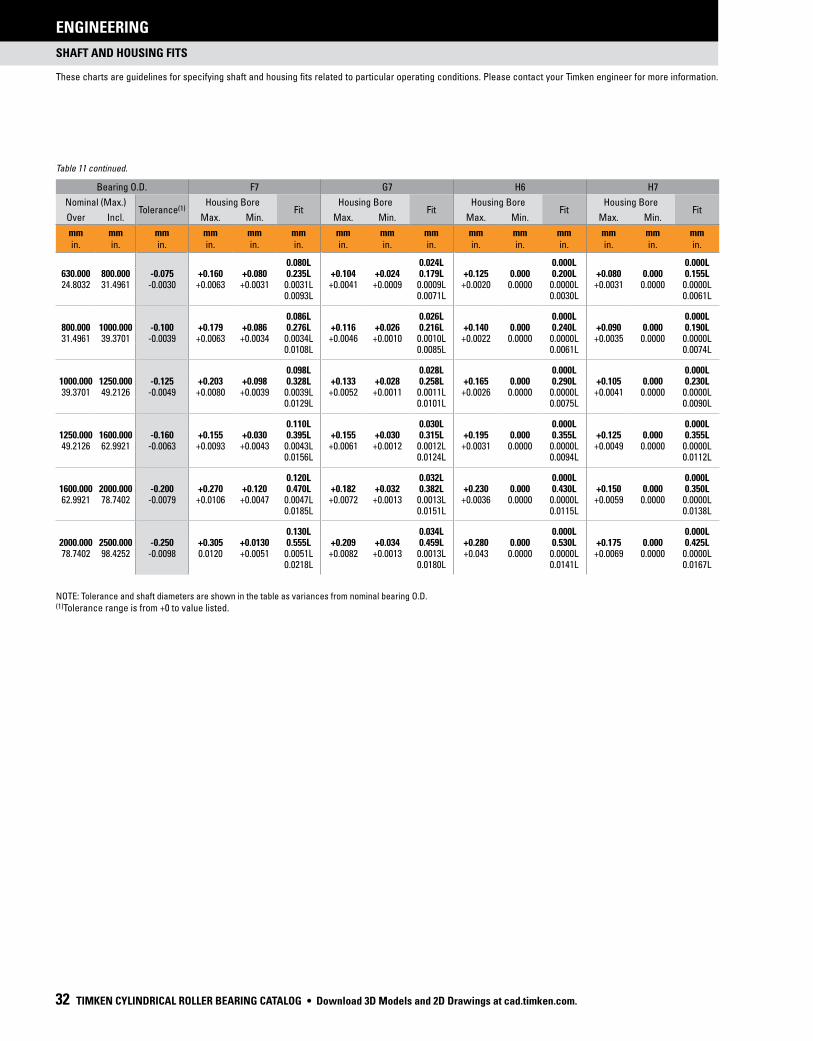
SHAFT AND HOUSING FITS
These charts are guidelines for specifying shaft and housing fits related to particular operating conditions. Please contact your Timken engineer for more information.
ENGINEERING
32 TIMKEN CYLINDRICAL ROLLER BEARING CATALOG
TABLE 11. RADIAL BALL, SPHERICAL ROLLER AND CYLINDRICAL ROLLER BEARING HOUSING TOLERANCES
Bearing O.D. F7 G7 H6 H7
Nominal (Max.)Tolerance(1)
Housing BoreFit
Housing BoreFit
Housing BoreFit
Housing BoreFit
Over Incl. Max. Min. Max. Min. Max. Min. Max. Min.
mmin.
mmin.
mmin.
mmin.
mmin.
mmin.
mmin.
mmin.
mmin.
mmin.
mmin.
mmin.
mmin.
mmin.
mmin.
0.080L 0.024L 0.000L 0.000L630.000 800.000 -0.075 +0.160 +0.080 0.235L +0.104 +0.024 0.179L +0.125 0.000 0.200L +0.080 0.000 0.155L24.8032 31.4961 -0.0030 +0.0063 +0.0031 0.0031L +0.0041 +0.0009 0.0009L +0.0020 0.0000 0.0000L +0.0031 0.0000 0.0000L
0.0093L 0.0071L 0.0030L 0.0061L
0.086L 0.026L 0.000L 0.000L800.000 1000.000 -0.100 +0.179 +0.086 0.276L +0.116 +0.026 0.216L +0.140 0.000 0.240L +0.090 0.000 0.190L31.4961 39.3701 -0.0039 +0.0063 +0.0034 0.0034L +0.0046 +0.0010 0.0010L +0.0022 0.0000 0.0000L +0.0035 0.0000 0.0000L
0.0108L 0.0085L 0.0061L 0.0074L
0.098L 0.028L 0.000L 0.000L1000.000 1250.000 -0.125 +0.203 +0.098 0.328L +0.133 +0.028 0.258L +0.165 0.000 0.290L +0.105 0.000 0.230L39.3701 49.2126 -0.0049 +0.0080 +0.0039 0.0039L +0.0052 +0.0011 0.0011L +0.0026 0.0000 0.0000L +0.0041 0.0000 0.0000L
0.0129L 0.0101L 0.0075L 0.0090L
0.110L 0.030L 0.000L 0.000L1250.000 1600.000 -0.160 +0.155 +0.030 0.395L +0.155 +0.030 0.315L +0.195 0.000 0.355L +0.125 0.000 0.355L49.2126 62.9921 -0.0063 +0.0093 +0.0043 0.0043L +0.0061 +0.0012 0.0012L +0.0031 0.0000 0.0000L +0.0049 0.0000 0.0000L
0.0156L 0.0124L 0.0094L 0.0112L
0.120L 0.032L 0.000L 0.000L1600.000 2000.000 -0.200 +0.270 +0.120 0.470L +0.182 +0.032 0.382L +0.230 0.000 0.430L +0.150 0.000 0.350L62.9921 78.7402 -0.0079 +0.0106 +0.0047 0.0047L +0.0072 +0.0013 0.0013L +0.0036 0.0000 0.0000L +0.0059 0.0000 0.0000L
0.0185L 0.0151L 0.0115L 0.0138L
0.130L 0.034L 0.000L 0.000L2000.000 2500.000 -0.250 +0.305 +0.0130 0.555L +0.209 +0.034 0.459L +0.280 0.000 0.530L +0.175 0.000 0.425L78.7402 98.4252 -0.0098 0.0120 +0.0051 0.0051L +0.0082 +0.0013 0.0013L +0.043 0.0000 0.0000L +0.0069 0.0000 0.0000L
0.0218L 0.0180L 0.0141L 0.0167L
NOTE: Tolerance and shaft diameters are shown in the table as variances from nominal bearing O.D. (1)Tolerance range is from +0 to value listed.
Table 11 continued.
• Download 3D Models and 2D Drawings at cad.timken.com.

SHAFT AND HOUSING FITS
These charts are guidelines for specifying shaft and housing fits related to particular operating conditions. Please contact your Timken engineer for more information.
ENGINEERING
TIMKEN CYLINDRICAL ROLLER BEARING CATALOG 33
H8 J6 J7 K6 K7
Housing BoreFit
Housing BoreFit
Housing BoreFit
Housing BoreFit
Housing BoreFit
Max. Min. Max. Min. Max. Min. Max. Min. Max. Min.
mmin.
mmin.
mmin.
mmin.
mmin.
mmin.
mmin.
mmin.
mmin.
mmin.
mmin.
mmin.
mmin.
mmin.
mmin.
0.000L 0.010T 0.024T 0.050T 0.080T800.000 +0.050 0.000 0.125L +0.040 -0.010 0.115L +0.056 -0.024 0.131L 0.000 -0.050 0.075L 0.000 -0.080 0.075L
+0.0049 0.0000 0.0000L +0.0016 -0.0004 0.0004T +0.0022 -0.0009 0.0009T 0.0000 -0.0020 0.0020T 0.0000 -0.0031 0.0031T0.0079L 0.0046L 0.0052L 0.0030L 0.0030L
0.000L 0.010T 0.026T 0.056T 0.090T1000.000 +0.056 0.000 0.156L +0.046 -0.010 0.146L +0.064 -0.026 0.164L 0.000 -0.056 0.100L 0.000 -0.090 0.100L
+0.0055 0.0000 0.0000L +0.0018 -0.0004 0.0004T +0.0025 -0.0010 0.0010T 0.0000 -0.0022 0.0022T 0.0000 -0.0035 0.0035T0.0094L 0.0057L 0.0064L 0.0039L 0.0039L
0.000L 0.010T 0.028T 0.066T 0.105T1000.000 1250.000 +0.066 0.000 0.191L +0.056 -0.010 0.181L +0.077 -0.028 0.202L 0.000 -0.066 0.125L 0.000 -0.105 0.125L
+0.0065 0.0000 0.0000L +0.0022 -0.0004 0.0004T +0.0030 -0.0011 0.0011T 0.0000 -0.0026 0.0026T 0.0000 -0.0041 0.0041T0.0114L 0.0071L 0.0079L 0.0049L 0.0049L
0.000L 0.010T 0.030T 0.078T 0.125T1250.000 1600.000 +0.078 0.000 0.238L +0.068 -0.010 0.228L +0.095 -0.030 0.255L 0.000 -0.078 0.160L 0.000 -0.125 0.160L
+0.0077 0.0000 0.0000L +0.0027 -0.0004 0.0004T +0.0037 -0.0012 0.0012T 0.0000 -0.0031 0.0031T 0.0000 -0.0049 0.0049T0.0104L 0.0090L 0.0100L 0.0063L 0.0063L
0.000L 0.110T 0.032T 0.092T 0.150T1600.000 2000.000 +0.092 0.000 0.292L +0.082 -0.010 0.282L +0.118 -0.032 0.318L 0.000 -0.092 0.200L 0.000 -0.150 0.200L
+0.0091 0.0000 0.0000L +0.0032 -0.0004 0.0004T +0.0046 -0.0013 0.0013T 0.0000 -0.0036 0.0036T 0.0000 -0.0059 0.0059T0.0170L 0.0111L 0.0125L 0.0079L 0.0079L
0.000L 0.010T 0.034T 0.110T 0.175T2000.000 2500.000 +0.110 0.000 0.360L +0.100 -0.010 0.350L +0.141 -0.034 0.391L 0.000 -0.110 0.250L 0.000 -0.175 0.250L
+0.0110 0.0000 0.0000L +0.0039 -0.0004 0.0004T +0.0056 -0.0013 0.0013T 0.0000 -0.0043 0.0043T 0.0000 -0.0069 0.0069T0.0208L 0.0137L 0.0154L 0.0098L 0.0098L
Download 3D Models and 2D Drawings at cad.timken.com. •

SHAFT AND HOUSING FITS
These charts are guidelines for specifying shaft and housing fits related to particular operating conditions. Please contact your Timken engineer for more information.
ENGINEERING
34 TIMKEN CYLINDRICAL ROLLER BEARING CATALOG
TABLE 12. RADIAL BALL, SPHERICAL ROLLER AND CYLINDRICAL ROLLER BEARING HOUSING TOLERANCES
Bearing O.D. M6 M7 N6 N7
Nominal (Max.)Tolerance(1)
Housing BoreFit
Housing BoreFit
Housing BoreFit
Housing BoreFit
Over Incl. Max. Min. Max. Min. Max. Min. Max. Min.
mmin.
mmin.
mmin.
mmin.
mmin.
mmin.
mmin.
mmin.
mmin.
mmin.
mmin.
mmin.
mmin.
mmin.
mmin.
0.015T 0.018T 0.020T 0.023T10.000 18.000 -0.008 -0.004 -0.015 0.004L 0.000 -0.018 0.008L -0.009 -0.020 0.001T -0.005 -0.023 0.003L0.3937 0.7087 -0.0003 -0.0002 -0.0006 0.0006T 0.0000 -0.0007 0.0007T -0.0004 -0.0008 0.0008T -0.0002 -0.0009 0.0009T
0.0001L 0.0003L 0.0001T 0.0001L
0.017T 0.021T 0.024T 0.028T18.000 30.000 -0.009 -0.004 -0.017 0.005L 0.000 -0.021 0.009L -0.007 -0.028 0.002T -0.007 -0.028 0.002L0.7087 1.1811 -0.0035 -0.0002 -0.0007 0.0007T 0.0000 -0.0008 0.0008T -0.0004 -0.0009 0.0009T -0.0003 -0.0011 0.0011T
0.00015L 0.0035L 0.00005T 0.00005L
0.020T 0.025T 0.028T 0.033T30.000 50.000 -0.011 -0.004 -0.020 0.007L 0.000 -0.025 0.011L -0.012 -0.028 0.001T -0.008 -0.033 0.003L1.1811 1.9685 -0.0045 -0.0002 -0.0008 0.0008T 0.0000 -0.0010 0.0010T -0.0005 -0.0011 0.0011T -0.0003 -0.0013 0.0013T
0.00025L 0.00045L 0.00005T 0.00015L
0.024T 0.030T 0.033T 0.039T50.000 80.000 -0.013 -0.005 -0.024 0.008L 0.000 -0.030 0.013L -0.014 -0.033 0.001T -0.009 -0.039 0.004L1.9685 3.1496 -0.0005 -0.0002 -0.0009 0.0009T 0.0000 -0.0012 0.0012T -0.0006 -0.0013 0.0013T -0.0004 -0.0015 0.0015T
0.0003L 0.0005L 0.0001T 0.0001L
0.028T 0.035T 0.038T 0.045T80.000 120.000 -0.015 -0.006 -0.028 0.009L 0.000 -0.035 0.015L -0.016 -0.038 0.001T -0.010 -0.045 0.005L3.1496 4.7244 -0.0006 -0.0002 -0.0011 0.0011T 0.0000 -0.0014 0.0014T -0.0006 -0.0015 0.0015T -0.0004 -0.0018 0.0018T
0.0004L 0.0006L 0.0000T 0.0002L
0.033T 0.040T 0.045T 0.061T120.000 150.000 -0.018 -0.008 -0.033 0.010L 0.000 -0.040 0.018L -0.020 -0.045 0.002T -0.012 -0.052 0.018L4.7244 5.9055 -0.0007 -0.0003 -0.0013 0.0013T 0.0000 -0.0016 0.0016T -0.0008 -0.0018 0.0018T -0.0005 -0.0020 0.0020T
0.0004L 0.0007L 0.0001T 0.0002L
0.033T 0.040T 0.045T 0.052T150.000 180.000 -0.025 -0.008 -0.033 0.017L 0.000 -0.040 0.025L -0.020 -0.045 0.005T -0.012 -0.052 0.013L5.9055 7.0866 -0.0010 -0.0003 -0.0013 0.0013T 0.0000 -0.0016 0.0016T -0.0008 -0.0018 0.0018T -0.0005 -0.0020 0.0020T
0.0007L 0.0010L 0.0002T 0.0005L
0.037T 0.046T 0.051T 0.060T180.000 250.000 -0.030 -0.008 -0.037 0.022L 0.000 -0.046 0.030L -0.022 -0.051 0.008T -0.014 -0.060 0.016L7.0866 9.8425 -0.0012 -0.0003 -0.0015 0.0015T 0.0000 -0.0018 0.0018T -0.0009 -0.0020 0.0020T -0.0006 -0.0024 0.0024T
0.0009L 0.0012L 0.0003T 0.0006L
0.041T 0.052T 0.057T 0.066T250.000 315.000 -0.035 -0.009 -0.041 0.026L 0.000 -0.052 0.035L -0.025 -0.057 0.010T -0.014 -0.066 0.021L9.8425 12.4016 -0.0014 -0.0004 -0.0016 0.0016T 0.0000 -0.0020 0.0020T -0.0010 -0.0022 0.0022T -0.0006 -0.0026 0.0025T
0.0010L 030014L 0.0004T 0.0008L
0.046T 0.057T 0.062T 0.073T315.000 400.000 -0.040 -0.010 -0.046 0.030L 0.000 -0.057 0.040L -0.026 -0.062 0.014T -0.016 -0.073 0.024L12.4016 15.7480 -0.0016 -0.0004 -0.0018 0.0018T 0.0000 -0.0022 0.0022T -0.0006 -0.0029 0.0024T -0.0006 -0.0029 0.0029T
0.0012L 0.0016L 0.0006T 0.0010L
0.050T 0.063T 0.067T 0.080T400.000 500.000 -0.045 -0.010 -0.050 0.035L 0.000 -0.063 0.045L -0.027 -0.067 0.018T -0.017 -0.080 0.028L15.7480 19.6850 -0.0018 -0.0004 -0.0020 0.0020T 0.0000 -0.0025 0.0025T -0.0011 -0.0026 0.0026T -0.0007 -0.0031 0.0031T
0.0014L 0.0018L 0.0007T 0.0011L
0.070T 0.096T 0.088T 0.114T500.000 630.000 -0.050 -0.026 -0.070 0.024L -0.026 -0.096 0.024L -0.044 -0.088 0.006T -0.044 -0.114 0.006L19.6850 24.8032 -0.0020 -0.0010 -0.0028 0.0028T -0.0010 -0.0038 0.0038T -0.0017 -0.0035 0.0035T -0.0017 -0.0045 0.0045T
0.0010L 0.0010L 0.0003T 0.0003L
NOTE: Tolerance and shaft diameters are shown in the table as variances from nominal bearing O.D. (1)Tolerance range is from +0 to value listed.
• Download 3D Models and 2D Drawings at cad.timken.com.

SHAFT AND HOUSING FITS
These charts are guidelines for specifying shaft and housing fits related to particular operating conditions. Please contact your Timken engineer for more information.
ENGINEERING
TIMKEN CYLINDRICAL ROLLER BEARING CATALOG 35
P6 P7
Housing BoreFit
Housing BoreFit
Max. Min. Max. Min.
mmin.
mmin.
mmin.
mmin.
mmin.
mmin.
0.026T 0.029T-0.015 -0.026 0.007T -0.011 -0.029 0.003T-0.0006 -0.0010 0.0010T -0.0004 -0.0011 0.0011T
0.0003T 0.0001T
0.031T 0.035T-0.018 -0.031 0.009T -0.014 -0.035 0.005T-0.0007 -0.0012 0.0012T -0.0006 -0.0014 0.0014T
0.00015L 0.00005L 0.00035T 0.0025T
0.037T 0.042T-0.021 -0.037 0.010T -0.017 -0.042 0.006T-0.0008 -0.0015 0.0015T -0.0007 -0.0017 0.0017T
0.00025L 0.00045L 0.00015L 0.00035T 0.0025T
0.045T 0.051T-0.026 -0.045 0.013T -0.021 -0.051 0.008T-0.0010 -0.0018 0.0018T -0.0008 -0.0020 0.0020T
0.0005T 0.0003T
0.052T 0.059T120.000 -0.030 -0.052 0.015T -0.024 -0.059 0.009T
-0.0012 -0.0020 0.0020T -0.0009 -0.0023 0.0023T0.0006T 0.0003T
0.061T 0.068T120.000 150.000 -0.036 -0.061 0.018T -0.028 -0.068 0.010T
-0.0014 -0.0024 0.0024T -0.0011 -0.0027 0.0027T0.0007T 0.0004T
0.061T 0.068T150.000 180.000 -0.036 -0.061 0.011T -0.028 -0.068 0.003T
-0.0014 -0.0024 0.0024T -0.0011 -0.0027 0.0027T0.0004T 0.0001T
0.070T 0.079T180.000 250.000 -0.041 -0.070 0.011T -0.033 -0.079 0.003T
-0.0016 -0.0028 0.0028T -0.0013 -0.0031 0.0031T0.0004T 0.0001T
0.079T 0.088T250.000 315.000 -0.047 -0.079 0.012T -0.036 -0.088 0.001T
-0.0019 -0.0031 0.0031T -0.0014 -0.0035 0.0035T0.0005T 0.0000T
0.087T -0.098 0.098T315.000 400.000 -0.051 -0.087 0.011T -0.041 0.001T
-0.0020 -0.0034 0.0034T -0.0016 -0.0039 0.0039T0.0004T 0.0000T
0.095T 0.108T400.000 500.000 -0.055 -0.095 0.010T -0.045 -0.108 0.000T
-0.0022 -0.0037 0.0037T -0.0018 -0.0043 0.0043T0.0004T 0.0000T
0.122T 0.148T500.000 630.000 -0.078 -0.122 0.028T -0.078 -0.148 0.028T
-0.0031 -0.0048 0.0048T -0.0031 -0.0058 0.0058T0.0011T 0.0011T
Continued on next page.
Download 3D Models and 2D Drawings at cad.timken.com. •

SHAFT AND HOUSING FITS
These charts are guidelines for specifying shaft and housing fits related to particular operating conditions. Please contact your Timken engineer for more information.
ENGINEERING
36 TIMKEN CYLINDRICAL ROLLER BEARING CATALOG
TABLE 12. RADIAL BALL, SPHERICAL ROLLER AND CYLINDRICAL ROLLER BEARING HOUSING TOLERANCES
Bearing O.D. M6 M7 N6 N7
Nominal (Max.)Tolerance(1)
Housing BoreFit
Housing BoreFit
Housing BoreFit
Housing BoreFit
Over Incl. Max. Min. Max. Min. Max. Min. Max. Min.
mmin.
mmin.
mmin.
mmin.
mmin.
mmin.
mmin.
mmin.
mmin.
mmin.
mmin.
mmin.
mmin.
mmin.
mmin.
0.080T 0.110T 0.100T 0.130T630.000 800.000 -0.075 -0.030 -0.080 0.045L -0.030 -0.110 0.045L -0.050 -0.100 0.025T -0.050 -0.130 0.025L24.8032 31.4961 -0.0030 -0.0012 -0.0031 0.0031T -0.0012 -0.0043 0.0043T -0.0020 -0.0039 0.0039T -0.0020 -0.0051 00051T
0.0018L 0.0018L 0.0010T 0.0010L
0.090T 0.124T 0.112T 0.146T800.000 1000.000 -0.100 -0.034 -0.090 0.066L -0.034 -0.124 0.066L -0.056 -0.112 0.044T -0.056 -0.146 0.044L31.4961 39.3701 -0.0039 -0.0013 -0.0035 0.0035T -0.0013 -0.0049 0.0049T -0.0022 -0.0044 0.0044T -0.0022 -0.0057 0.0057T
0.0026L 0.0026L 0.0017T 0.0017L
0.106T 0.145T 0.132T 0.171T1000.000 1250.000 -0.125 -0.040 -0.106 0.085L -0.040 -0.145 0.085L -0.066 -0.132 0.059T -0.066 -0.171 0.059L39.3701 49.2126 -0.0049 -0.0016 -0.0042 0.0042T -0.0016 -0.0057 0.0057T -0.0026 -0.0052 0.0052T -0.0026 -0.0067 0.0067T
0.0033L 0.0033L 0.0023T 0.0023L
0.126T 0.173T 0.156T 0.203T1250.000 1600.000 -0.160 -0.048 -0.126 0.112L -0.048 -0.173 0.112L -0.078 -0.156 0.082T -0.078 -0.203 0.082L49.2126 62.9921 -0.0063 -0.0019 -0.0050 0.0050T -0.0019 -0.0068 0.0068T -0.0031 -0.0061 0.0061T -0.0031 -0.0080 0.0080T
0.0044L 0.0044L 0.0032T 0.0023L
0.150T 0.208T 0.184T 0.242T1600.000 2000.000 -0.200 -0.058 -0.150 0.142L -0.058 -0.208 0.142L -0.092 -0.184 0.108T -0.092 -0.242 0.108L62.9921 78.7402 -0.0079 -0.0023 -0.0059 0.0059T -0.0023 -0.0082 0.0082T -0.0036 -0.0072 0.0072T -0.0036 -0.0095 0.0095T
0.0056L 0.0056L 0.0043T 0.0043L
0.178T 0.243 0.285T 0.285T2000.000 2500.000 -0.250 -0.068 -0.178 0.182L -0.068 -0.243 0.182L -0.110 -0.220 0.140T -0.110 -0.285 0.140L78.7402 98.4252 -0.0098 -0.0027 -0.0070 0.0070T -0.0027 -0.0096 0.0096T -0.0043 -0.0087 0.112T -0.0043 -0.0112 0.0112T
0.0071L 0.0071L 0.055T 0.0055L
NOTE: Tolerance and shaft diameters are shown in the table as variances from nominal bearing O.D. (1)Tolerance range is from +0 to value listed.
Table 12 continued.
• Download 3D Models and 2D Drawings at cad.timken.com.

SHAFT AND HOUSING FITS
These charts are guidelines for specifying shaft and housing fits related to particular operating conditions. Please contact your Timken engineer for more information.
ENGINEERING
TIMKEN CYLINDRICAL ROLLER BEARING CATALOG 37
P6 P7
Housing BoreFit
Housing BoreFit
Max. Min. Max. Min.
mmin.
mmin.
mmin.
mmin.
mmin.
mmin.
0.138T 0.168T630.000 800.000 -0.088 -0.138 0.013T -0.088 -0.168 0.013T
-0.0035 -0.0054 0.0054T -0.0035 -0.0066 0.0066T0.0005T 0.0005T
0.156T 0.190T800.000 1000.000 -0.100 -0.156 0.000T -0.100 -0.190 0.000T
-0.0039 -0.0061 0.0061T -0.0039 -0.0075 0.0075T0.0000T 0.0000T
0.186T 0.225T1000.000 1250.000 -0.120 -0.186 0.005L -0.120 -0.225 0.005T
-0.0047 -0.0073 0.0073T -0.0047 -0.0089 0.0089T0.0002L 0.0002T
0.218T 0.265T1250.000 1600.000 -0.140 -0.218 0.020L -0.140 -0.265 0.020L
-0.0055 -0.0086 0.0086T -0.0055 -0.0104 0.0104T0.0008L 0.0008L
0.262T 0.320T1600.000 2000.000 -0.170 -0.262 0.030L -0.170 -0.320 0.030L
-0.0067 -0.0103 0.0103T -0.0067 -0.0126 0.0126T0.0012L 0.0012L
0.305T 0.370T2000.000 2500.000 -0.195 -0.305 0.055L -0.195 -0.370 0.055L
-0.0077 -0.0120 0.0120T -0.0077 -0.0146 0.0146T0.0021L 0.0021L
Download 3D Models and 2D Drawings at cad.timken.com. •

TWO-ROW
CYLINDRICAL ROLLER BEARINGS
38 TIMKEN CYLINDRICAL ROLLER BEARING CATALOG
SHAFT AND HOUSING FITS
ENGINEERING
5200, A5200 METRIC SERIES SHAFT AND HOUSING FITS AND TOLERANCES
TABLE 14. HOUSING FITS
Bearing O.D. O.D. Tolerance(1)
Slip Fit Stationary Outer Ring
Press Fit Rotating Outer Ring
Housing Diameter Fit Housing Diameter Fit
Over Incl. Max. Min. Max. Min.
mmin.
mmin.
mmin.
mmin.
mmin.
mmin.
mmin.
mmin.
mmin.
mmin.
mmin.
– 180 -0.025 +0.022 -0.015 0.015T 0.046L -0.025 -0.056 0.056T 0.000L– 7.0866 -0.0010 +0.0008 -0.0006 0.0006T 0.0018L -0.0010 -0.0022 0.0022T 0.0000L
180 200 -0.030 +0.018 -0.018 0.018T 0.048L -0.030 -0.066 0.066T 0.000L7.0866 7.8740 -0.0012 +0.0007 -0.0007 0.0007T 0.0019L -0.0012 -0.0026 0.0026T 0.0000L
200 230 -0.030 +0.023 -0.018 0.018T 0.053L -0.030 -0.066 0.066T 0.000L7.874 9.0551 -0.0012 +0.0009 -0.0007 0.0007T 0.0021L -0.0012 -0.0026 0.0026T 0.0000L
230 250 -0.030 +0.028 -0.018 0.018T 0.058L -0.030 -0.066 0.066T 0.000L9.0551 9.8425 -0.0012 +0.0011 -0.0007 0.0007T 0.0023L -0.0012 -0.0026 0.0026T 0.0000L
250 270 -0.036 +0.028 -0.018 0.018T 0.064L -0.030 -0.071 0.071T 0.005L9.8425 10.6299 -0.0014 +0.0011 -0.0007 0.0007T 0.0025L -0.0012 -0.0028 0.0028T 0.0002L
270 310 -0.036 +0.033 -0.018 0.018T 0.069L -0.036 -0.071 0.071T 0.005L10.6299 12.2047 -0.0014 +0.0013 -0.0007 0.0007T 0.0027L -0.0014 -0.0028 0.0028T 0.0002L
310 400 -0.041 +0.038 -0.018 0.018T 0.079L -0.036 -0.076 0.079T 0.005L12.2047 15.7480 -0.0016 +0.0015 -0.0007 0.0007T 0.0031L -0.0014 -0.0030 0.0030T 0.0002L
400 440 -0.046 +0.041 -0.023 0.023T 0.086L -0.036 -0.086 0.086T 0.010L15.748 17.3228 -0.0018 +0.0016 -0.0009 0.0009T 0.0034L -0.0014 -0.0034 0.0034T 0.0004L
(1)Tolerance range is from +0 to value listed.
TABLE 13. SHAFT FITS(1)
Bearing Bore Bore Tolerance(2)
Press Fit Rotating Inner Ring
Slip Fit Stationary Inner Ring
Shaft Diameter Fit Shaft Diameter Fit
Over Incl. Max. Min. Max. Min.
mmin.
mmin.
mmin.
mmin.
mmin.
mmin.
mmin.
mmin.
mmin.
mmin.
mmin.
80 120 -0.020 +0.048 +0.025 0.025T 0.069T 0.000 -0.023 0.023L 0.020T3.1496 4.7236 -0.0008 +0.0019 +0.0010 0.0010T 0.0027T 0.0000 -0.0009 0.0009L 0.0008T
120 140 -0.025 +0.056 +0.030 0.030T 0.081T 0.000 -0.025 0.025L 0.025T4.7236 5.5108 -0.0010 +0.0022 +0.0012 0.0012T 0.0032T 0.0000 -0.0010 0.0010L 0.0010T
140 180 -0.025 +0.071 +0.046 0.046T 0.097T 0.000 -0.025 0.025L 0.025T5.5108 7.0856 -0.0010 +0.0028 +0.0018 0.0018T 0.0038T 0.0000 -0.0010 0.0010L 0.0010T
180 240 -0.030 +0.081 +0.051 0.051T 0.112T 0.000 -0.030 0.030L 0.030T7.0856 9.4476 -0.0012 +0.0032 +0.0020 0.0020T 0.0044T 0.0000 -0.0012 0.0012L 0.0012T
(1) When shaft is used as ring surface, hardness to be Rc58 minimum and surface finish to be 15 RMS.(2)Tolerance range is from +0 to value listed.
• Download 3D Models and 2D Drawings at cad.timken.com.

TWO-ROW
CYLINDRICAL ROLLER BEARINGS
TIMKEN CYLINDRICAL ROLLER BEARING CATALOG 39
SHAFT AND HOUSING FITS
ENGINEERING
TABLE 18. 5200 BEARINGS WITHOUT INNER RING SHAFT DIMENSIONS
Bearing Number
Slip Fit Housing(1) Press Fit Housing(1)
Max. Min. Max. Min.
mmin.
mmin.
mmin.
mmin.
5220 WS 121.064 121.044 121.036 121.0164.7663 4.7655 4.7652 4.7644
5222 WS 133.007 132.987 132.969 132.9495.2365 5.2357 5.235 5.2343
5224 WS 145.194 145.174 145.156 145.1365.7163 5.7155 5.7148 5.714
5226 WS 155.042 155.016 155.004 154.9786.104 6.103 6.1025 6.1015
5228 WS 168.529 168.504 168.491 168.4666.635 6.634 6.6335 6.6325
5230 WS 181.623 181.597 181.587 181.5597.1505 7.1495 7.149 7.148
5232 WS 193.713 193.688 193.675 193.657.6265 7.6255 7.625 7.624
5234 WS 205.562 205.537 205.524 205.4998.093 8.092 8.0915 8.0905
5236 WS 216.37 216.344 216.319 216.2948.5185 8.5175 8.5165 8.5155
5238 WS 229.032 229.001 228.994 228.9639.017 9.0158 9.0155 9.0143
5240 WS 242.296 242.265 242.245 242.2149.5392 9.538 9.5372 9.536
5244 WM 266.02 265.971 265.951 265.9210.4725 10.4713 10.4705 10.4693
5248WM 291.292 291.262 291.241 291.21111.4682 11.467 11.4662 11.465
(1)All shaft diameters are based on a housing bore to housing O.D. ratio of 0.7.
TABLE 15. 5200 METRIC SERIES RADIAL INTERNAL CLEARANCE (R6)
Bearing BoreRadial Internal
Clearance
Over Incl. Max. Min.
mmin.
mmin.
mmin.
mmin.
– 100 0.183 0.127– 3.937 0.0072 0.005
100 120 0.188 0.1273.937 4.7244 0.0074 0.005
120 140 0.208 0.1424.7244 5.5118 0.0082 0.0056
140 170 0.224 0.1525.5118 6.6929 0.0088 0.006
170 180 0.229 0.1526.6929 7.0866 0.009 0.006
180 220 0.254 0.1737.0866 8.6614 0.01 0.0068
220 240 0.269 0.1838.6614 9.4488 0.0106 0.0072
TABLE 16. 5200 METRIC SERIES INNER RING TOLERANCES
Bearing Bore Bore & Inner O.D.(1)
Width
Over Incl. +0
mmin.
mmin.
mmin.
mmin.
80 120 -0.020 -0.2033.1496 4.7244 -0.0008 -0.0080
120 80 -0.025 -0.2544.7244 7.0866 -0.0010 -0.0100
180 250 -0.030 -0.3057.0866 9.8425 -0.0012 -0.0120
(1)Tolerance range is from +0 to value listed.
TABLE 17. 5200 METRIC SERIES OUTER RING TOLERANCES
Bearing BoreO.D.(1)
Width
Over Incl. +0
mmin.
mmin.
mmin.
mmin.
150 180 -0.025 +0.0365.9055 7.0866 -0.0010 +0.0014
180 250 -0.030 +0.0417.0866 9.8425 -0.0012 +0.0016
250 315 -0.036 +0.0469.8425 12.4016 -0.0014 +0.0018
315 400 -0.041 +0.05112.4016 15.748 -0.0016 +0.0020
400 500 -0.046 +0.05615.748 19.685 -0.0018 +0.0022
(1)Tolerance range is from +0 to value listed.
Download 3D Models and 2D Drawings at cad.timken.com. •

OPERATING TEMPERATURES
ENGINEERING
40 TIMKEN CYLINDRICAL ROLLER BEARING CATALOG
OPERATING TEMPERATURESBearings operate in a wide range of applications and environments.
In most cases, bearing operating temperature is not an issue.
Some applications, however, operate at extreme speeds or in
extreme temperature environments. In these cases, care must
be taken not to exceed the temperature limits of the bearing.
Minimum temperature limits are primarily based on lubricant
capability. Maximum temperature limits are most often based
on material and/or lubricant constraints, but also may be based
on accuracy requirements of the equipment that the bearings
are built into. These constraints/limitations are discussed below.
BEARING MATERIAL LIMITATIONSStandard bearing steels with a standard heat treatment cannot
maintain a minimum hardness of 58 HRC much above 120° C
(250° F).
Dimensional stability of Timken bearings is managed through the
proper selection of an appropriate heat-treat process. Standard
Timken tapered roller and ball bearings are dimensionally stabilized
from -54° C (-65° F) up to 120° C (250° F), while standard spherical
roller bearings are dimensionally stabilized up to 200° C (392° F) and
standard cylindrical roller bearings are stabilized up to 150° C
(302° F). Upon request, these bearings can be ordered to higher
levels of stability as listed below. These designations are in
agreement with DIN Standard 623.
TABLE 19.
Stability Designation
Maximum Operating Temperature
°C °F
S0 150 302
S1 200 392
S2 250 482
S3 300 572
S4 350 662
With dimensionally stabilized product, there still may be some
changes in dimensions during service as a result of microstructural
transformations. These transformations include the continued
tempering of martensite and decomposition of retained austenite.
The magnitude of change depends on the operating temperature,
the time at temperature and the composition and heat-treatment of
the steel.
Temperatures exceeding the limits shown in table 19 require
special high-temperature steel. Consult your Timken engineer for
availability of specific part numbers for non-standard heat
stability or high-temperature steel grades.
Suggested materials for use in balls, rings and rollers at various
operating temperatures are listed in table 20. Also listed
are chemical composition recommendations, hardness
recommendations and dimensional stability information.
Operating temperature affects lubricant film thickness and setting,
both of which directly influence bearing life. Extremely high
temperatures can result in a reduced film thickness that can lead
to asperity contact between contacting surfaces.
Operating temperature also can affect performance of cages,
seals and shields, which in turn can affect bearing performance.
Materials for these components and their operating temperature
ranges are shown in table 21.
LUBRICATION LIMITATIONSStarting torque in grease-lubricated applications typically increases
significantly at cold temperatures. Starting torque is not primarily
a function of the consistency or channel properties of the grease.
Most often, it is a function of the rheological properties of the grease.
The high-temperature limit for greases is generally a function of the
thermal and oxidation stability of the base oil in the grease and the
effectiveness of the oxidation inhibitors.
See the LUBRICATION AND SEALS section on page 45 for more
information on lubrication limitations.
EQUIPMENT REQUIREMENTSThe equipment designer must evaluate the effects of temperature
on the performance of the equipment being designed. Precision
machine tool spindles, for example, can be very sensitive to thermal
expansions. For some spindles, it is important that the temperature
rise over ambient be held to 20° C to 35° C (36° F to 45° F).
Most industrial equipment can operate at considerably higher
temperatures. Thermal ratings on gear drives, for example, are
based on 93° C (200° F). Equipment such as gas turbines operates
continuously at temperatures above 100° C (212° F). Running at high
temperatures for extended periods of time, however, may affect
shaft and housing fits, if the shaft and housing are not machined
and heat-treated properly .
Although bearings can operate satisfactorily up to 120° C (250° F),
• Download 3D Models and 2D Drawings at cad.timken.com.

OPERATING TEMPERATURES
ENGINEERING
TIMKEN CYLINDRICAL ROLLER BEARING CATALOG 41
an upper temperature limit of 80° C to 95° C (176° F to 203° F) is more
practical. Higher operating temperatures increase the risk of
damage from transient temperature spikes. Prototype testing of the
application can help define the operating temperature range and
should be conducted if possible. It is the responsibility of the
equipment designer to weigh all relevant factors and make the final
determination of satisfactory operating temperature.
MaterialApproximate Chemical
Analysis %Temp.
˚F
Hard-nessHRC
-73 ̊C
-100 ̊F
-54 ̊C
-65 ̊F
-17 ̊C
0˚ F38 ̊C
100 ̊F
93 ̊C
200˚ F121 ̊C
250˚ F149 ̊C
300˚ F204 ̊C
400˚ F260˚ C
500˚ F316 ̊C
600˚ F371 ̊C
700˚ F427˚ C
800˚ F
Low-alloy carbon- chromium bearing steels. 52100 and others per ASTM
A295
1C0.5–1.5Cr0.35Mn
70 60STANDARD DIMENSIONAL
STABILIZATION<0.0001 in./in dimensional change in
2500 hours at 100˚ C (212˚ F). Good oxidation resistance.
Low-alloy carbon- chromium bearing steels. 52100 and others per ASTM
A295
1C0.5–1.5Cr0.35Mn
70350450
585654
Heat stabilized per FS136, <0.0001in./in dimensional change in 2500 hours at 149° C (300° F). When given a
stabilizing heat treatment, A295 steel is suitable for many applications in the 177°-232° C (350-450° F) range;
however, it is not as dimensionally stable as it is at temperatures below 177° C (350° F).
If utmost stability is required, use materials in the 316° C (600° F) group below.
Deep-hardening steels for heavy sec-tions per ASTM A485
1C 1–1.8Cr
1–1.5Mn .06Si
70450600
585552
As heat-treated and tempered, it is stabilized, <0.0001 in./in dimensional change in 2500 hours at 149° C (300° F).
Carburizing steels per ASTM A534
a) low alloy 4118, 8X19, 5019, 8620
(Ni-Moly grades) b) high nickel 3310
Ni-Moly: 0.2C, 0.4-2.0Mn, 0.3-0.8Cr, 0-2.0Ni, 0-0.3Mo
.0.1C, 1.5Cr, 0.4Mn, 3.5Ni
70 58
Nickel-Moly grades of steel frequently used to achieve extra ductility in inner rings for locking device bearings. 3311 and others
used for extra-thick-section rings.
Corrosion-resistant 440C stainless steel
per ASTM A756
1C 18Cr70 58
Excellent corrosion resistance.
Corrosion-resistant 440C stainless steel
per ASTM A756
1C 18Cr 70450600
585552
As heat stabilized for maximum hardness at high temperatures (FS238). Good oxidation resistance at higher temperatures. Note load capacity drops off more rapidly at higher temperatures than M50 shown below,
which should be considered if loads are high, <0.0001 in./in dimensional change in 1200 hours.
M-50 medium
high speed
4Cr 4Mo1V 0.8C
70450600
605957
Suggested where stable high hardness at elevated temperature is required, <0.0001 in./in dimensional change in 1200 hours at 316° C (600° F).
Tables 20 and 21 provide standard operating temperatures for
common bearing component materials. They should be used for
reference purposes only. Other bearing component materials
are available on request. Contact your Timken engineer for more
information.
TABLE 20. OPERATING TEMPERATURES FOR BEARING COMPONENT MATERIALS
Note: Dimensional stability data shown above is the permanent metallurgical growth and/or shrinkage only. Thermal expansion
effects are not included. For operating temperatures above 427° C (800° F), consult your Timken engineer.
Download 3D Models and 2D Drawings at cad.timken.com. •
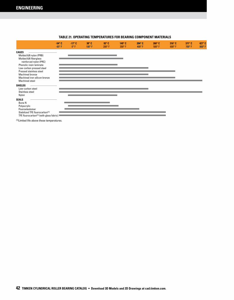
BEARING TYPES AND CAGES
ENGINEERING
42 TIMKEN CYLINDRICAL ROLLER BEARING CATALOG
ENGINEERING
CAGES Molded 6/6 nylon (PRB) Molded 6/6 fiberglass reinforced nylon (PRC) Phenolic resin laminate Low-carbon pressed steel Pressed stainless steel Machined bronze Machined iron-silicon bronze Machined steel
SHIELDS Low-carbon steel Stainless steel Nylon
SEALS Buna N Polyacrylic Fluoroelastomer Stabilized TFE fluorocarbon(1)
TFE fluorocarbon(1) (with glass fabric)
(1)Limited life above these temperatures.
TABLE 21. OPERATING TEMPERATURES FOR BEARING COMPONENT MATERIALS
• Download 3D Models and 2D Drawings at cad.timken.com.

BEARING TYPES AND CAGES
ENGINEERING
TIMKEN CYLINDRICAL ROLLER BEARING CATALOG 43
HEAT GENERATION AND DISSIPATION
ENGINEERING
Bearing operating temperature is dependent upon a number
of factors, including heat generation of all contributing heat
sources, heat flow rate between sources and the ability of the
system to dissipate the heat. Heat sources include such things as
bearings, seals, gears, clutches and oil supply. Heat dissipation is
affected by many factors, including shaft and housing materials
and designs, lubricant circulation and external environmental
conditions. These and other factors are discussed in the following
sections.
HEAT GENERATION
Under normal operating conditions, most of the torque and heat
generated by the bearing is caused by the elastohydrodynamic
losses at the roller/ring contacts.
Heat generation is the product of bearing torque and speed. The
following equation is used to calculate the heat generated.
Qgen = k4n M
If the bearing is a cylindrical roller bearing, the torque calculations
are given in the subsequent sections.
HEAT DISSIPATION
The problem of determining the heat flow from a bearing in a
specific application is rather complex. In general, it can be said
that factors affecting the rate of heat dissipation include the
following:
1. Temperature gradient from the bearing to the housing. This is
affected by size configuration of the house and any external
cooling such as fans, water cooling or fan action of the rotating
components.
2. Temperature gradient from the bearing to the shaft. Any other
heat sources, such as gears and additional bearings and
their proximity to the bearing considered, will influence the
temperature of the shaft.
3. The heat carried away by a circulating oil system.
To what extent nos. 1 and 2 can be controlled will depend on
the application. The heat-dissipation modes include conduction
through the system, convection along the inside and outside
surfaces of the system, as well as radiation exchange to and
from neighboring structures. In many applications, overall heat
dissipation can be divided into two categories – heat removed by
circulating oil and heat removed through the structure.
Heat dissipation by circulating oil
The amount of heat removed by the lubricant can be controlled
more easily. In a splash lubrication system, cooling coils may be
used to control the bulk oil temperature.
The amount of heat carried away in a circulating oil system by
the lubricant can be approximated from the following equations.
Qoil = k6 Cpρf (θo - θi)
Where:
k6 = 1.67 x 10⁻⁵ for Qoil in W
= 1.67 x 10⁻² for Qoil in Btu/min
If the circulating lubricant is petroleum oil, the heat removed is
further approximated by the following:
Qoil = k5 f (θo - θi)
The following factors apply to the heat generation and dissipation
equations listed on this page.
Where:
k5 = 28 for Qoil in W when f in L/min and θ in °C
= 0.42 for Qoil in Btu/min when f in U.S. pt/min
and θ in °F
HEAT GENERATION AND DISSIPATION
Download 3D Models and 2D Drawings at cad.timken.com. •

TORQUE
ENGINEERING
44 TIMKEN CYLINDRICAL ROLLER BEARING CATALOG
CYLINDRICAL ROLLER BEARINGSThe torque equations for cylindrical roller bearings are given as
follows, where the coefficients are based on series and found
in the following table:
M = f
1 F
ß dm + 10-7 f
0 (v x n)
2/3 dm3 if (v x n) 2000
f1 F
ß dm + 160 x 10-7 f
0 dm3 if (v x n) < 2000
Note that the viscosity is in units of centistokes. The load term
(Fß) depends on the bearing type as follows:
Radial cylindrical roller: Fß = max 0.8Fa cot
or Fr
﹛ ﹛
TABLE 22. COEFFICIENTS FOR THE TORQUE EQUATION
Bearing TypeDimension
Seriesf0
f1
Single-row cylindrical roller
bearings with cage
10
02
22
03
23
04
2
2
3
2
4
2
0.00020
0.00030
0.00040
0.00035
0.00040
0.00040
Single-row cylindrical roller
bearings full-complement
18
29
30
22
23
5
6
7
8
12
0.00055
0.00055
0.00055
0.00055
0.00055
Double-row cylindrical roller
bearings full-complement
48
49
50
9
11
13
0.00055
0.00055
0.00055
TORQUE
RUNNING TORQUE-MThe rotational resistance of a rolling bearing is dependent on load,
speed, lubrication conditions and bearing internal characteristics.
The following formulas yield approximations to values of bearing
running torque. The formulas apply to bearings lubricated by oil.
For bearings lubricated by grease or oil mist, torque is usually
lower, although for grease lubrication this depends on amount
and consistency of the grease. The formulas also assume the
bearing running torque has stabilized after an initial period
referred to as running-in.
( )
• Download 3D Models and 2D Drawings at cad.timken.com.

LUBRICATION
TIMKEN CYLINDRICAL ROLLER BEARING CATALOG 45
LUBRICATIONTo help maintain a bearing’s antifriction
characteristics, lubrication is needed to:
• Minimize rolling resistance due to
deformation of the rolling elements
and raceway under load by separating
the mating surfaces.
• Minimize sliding friction occurring
between rolling elements, raceways and cage.
• Transfer heat (with oil lubrication).
• Protect from corrosion and, with grease lubrication,
from contaminant ingress.
LUBRICATION AND SEALS
Download 3D Models and 2D Drawings at cad.timken.com. •

LUBRICATION
46 TIMKEN CYLINDRICAL ROLLER BEARING CATALOG
LUBRICATIONThe wide range of bearing types and operating conditions
precludes any simple, all-inclusive statement or guideline
allowing the selection of the proper lubricant. At the design
level, the first consideration is whether oil or grease is best for
the particular operation. The advantages of oil and grease are
outlined in the table below. When heat must be carried away
from the bearing, oil must be used. It is almost always preferred
for very high-speed applications.
TABLE 23. ADVANTAGES OF OIL AND GREASE
Oil Grease
Carries heat away from the bearings
Simplifies seal design and acts as a sealant
Carries away moisture and particulate matter
Permits prelubrication of sealed or shielded bearings
Easily controlled lubricationGenerally requires lessfrequent lubrication
European REACH compliance
Timken-branded lubricants, greases and similar products sold
in stand-alone containers or delivery systems are subject to the
European REACH (Registration, Evaluation, Authorization and
Restriction of CHemicals) directive. For import into the European
Union, Timken can sell and provide only those lubricants and
greases that are registered with ECHA (European CHemical Agency).
For further information, please contact your Timken engineer.
OIL LUBRICATIONOils used for bearing lubrication should be high-quality mineral
oils or synthetic oils with similar properties. Selection of the
proper type of oils depends on bearing speed, load, operating
temperature and lubrication method. Some features and
advantages of oil lubrication, in addition to the above are:
• Oil is a better lubricant for high speeds or high tempera-
tures. It can be cooled to help reduce bearing temperature.
• It is easier to handle and control the amount of lubricant
reaching the bearing. It is harder to retain in the bearing.
Lubricant losses may be higher than with grease.
• Oil can be introduced to the bearing in many ways, such as
drip-feed, wick-feed, pressurized circulating systems, oil bath
or air-oil mist. Each is suited for certain types of applications.
• Oil is easier to keep clean for recirculating systems.
Oil may be introduced to the bearing housing in many ways. The
most common systems are:
• Oil bath. The housing is designed to provide a sump
through which the rolling elements of the bearing will pass.
Generally, the oil level should be no higher than the center
point of the lowest rolling element. If speed is high, lower
oil levels should be used to reduce churning. Gages or
controlled elevation drains are used to achieve and
maintain the proper oil level.
• Circulating system. This system has the advantages of:
• An adequate supply of oil for both cooling and
lubrication.
• Metered control of the quantity of oil delivered to
each bearing.
• Removal of contaminants and moisture from the
bearing by flushing action.
• Suitability for multiple bearing installations.
• Large reservoir, which reduces deterioration.
Increased lubricant life provides economical
efficiency.
• Incorporation of oil-filtering devices.
• Positive control to deliver the lubricant where needed.
• A typical circulating oil system consists of an oil
reservoir, pump, piping and filter. A heat exchange
may be required.
• Oil-mist lubrication. Oil-mist lubrication systems are used
in high-speed, continuous-operation applications. This
system permits close control of the amount of lubricant
reaching the bearings. The oil may be metered, atomized
by compressed air and mixed with air, or it may be picked
up from a reservoir using a venturi effect. In either case,
the air is filtered and supplied under sufficient pressure to
assure adequate lubrication of the bearings. Control of this
type of lubrication system is accomplished by monitoring the
operating temperatures of the bearings being lubricated. The
continuous passage of the pressurized air and oil through the
labyrinth seals used in the system prevents the entrance of
contaminants from the atmosphere to the system.
The successful operation of this type of system is based
upon the following factors:
• Proper location of the lubricant entry ports in relation to the bearings being lubricated.
• Avoidance of excessive pressure drops across void spaces within the system.
• Proper air pressure and oil quantity ratio to suit the particular application.
• Adequate exhaust of the air-oil mist after lubrication has been accomplished.
To ensure “wetting” of the bearings, and to prevent
possible damage to the rolling elements and rings, it is
• Download 3D Models and 2D Drawings at cad.timken.com.

LUBRICATION
TIMKEN CYLINDRICAL ROLLER BEARING CATALOG 47
Lubricating oils are commercially available in many forms for
automotive, industrial, aircraft and other uses. Oils are classified
as either petroleum types (refined from crude oil) or synthetic
types (produced by chemical synthesis).
PETROLEUM OILS
Petroleum oils are made from a petroleum hydrocarbon derived
from crude oil, with additives to improve certain properties.
Petroleum oils are used for nearly all oil-lubricated applications
of bearings.
SYNTHETIC OILS
Synthetic oils cover a broad range of categories and include
polyalphaolefins, silicones, polyglycols and various esters. In
general, synthetic oils are less prone to oxidation and can operate
at extreme hot or cold temperatures. Physical properties, such as
pressure-viscosity coefficients, tend to vary between oil types;
use caution when making oil selections.
The polyalphaolefins (PAO) have a hydrocarbon chemistry that
parallels petroleum oil both in chemical structures and pressure-
viscosity coefficients. Therefore, PAO oil is mostly used in the
oil-lubricated applications of bearings when severe temperature
environments (hot and cold) are encountered or when extended
lubricant life is required.
The silicone, ester and polyglycol oils have an oxygen-based
chemistry that is structurally quite different from petroleum
oils and PAO oils. This difference has a profound effect on its
physical properties where pressure-viscosity coefficients can
be lower compared to mineral and PAO oils. This means that
these types of synthetic oils may actually generate a smaller
elastohydrodynamic (EHD) film thickness than a mineral or PAO
oil of equal viscosity at operating temperature. Reductions in
bearing fatigue life and increases in bearing wear could result
from this reduction of lubricant film thickness.
VISCOSITY
The selection of oil viscosity for any bearing application requires
consideration of several factors: load, speed, bearing setting,
type of oil and environmental factors. Since oil viscosity varies
inversely with temperature, a viscosity value must always be
stated with the temperature at which it was determined. High-
viscosity oil is used for low-speed or high-ambient-temperature
applications. Low-viscosity oil is used for high-speed or low-
ambient-temperature applications.
There are several classifications of oils based on viscosity grades.
The most familiar are the Society of Automotive Engineers (SAE)
classifications for automotive engine and gear oils. The American
Society for Testing and Materials (ASTM) and the International
Organization for Standardization (ISO) have adopted standard
viscosity grades for industrial fluids. Fig. 12 shows the viscosity
comparisons of ISO/ASTM with SAE classification systems at
40° C (104° F).
VISCOSITY CLASSIFICATION COMPARISON
Fig. 12. Comparison between ISO/ASTM grades (ISO 3448/ASTM D2442) and SAE grades (SAE J 300-80 for crankcase oils, SAE J 306-81 for axle and manual transmission oils).
2000
1500
1000
800
600
400
300
200
150
100
80
60
40
30
20
15
10
8
6
4
3
2
1500
1000
680
460
320
220
150
20
30
40
50
140
90
100
68
46
32
22
15
10
7
5
3
2
ISO/ASTMViscosity Grade
SAE Crankcase Oils
Viscosity Classification Comparison
SAE Gear Oil
10W min.
5W min.
250 min.
85W min.
80W min.
70W min.
10000
7500
50004000
3000
2000
1500
1000
700
500400
300
200
150
100
75
60
50
40
35
33
Kin
em
ati
c V
isc
osi
ty, C
en
tist
oke
s (c
St)
at
40˚
C (
104˚
F)
Vis
co
sity
, Sa
ybo
lt U
niv
ers
al S
ec
on
ds
(SU
S)
at
38˚
C (
100˚
F)
imperative that the oil-mist system be turned on for several
minutes before the equipment is started. The importance of
“wetting” the bearing before starting cannot be overstated,
and it also has particular significance for equipment that
has been idled for extended periods of time.
Download 3D Models and 2D Drawings at cad.timken.com. •

LUBRICATION
48 TIMKEN CYLINDRICAL ROLLER BEARING CATALOG
TYPICAL BEARING LUBRICATION OILS
In this section, the properties and characteristics of lubricants
for typical roller bearing applications are listed. These general
characteristics are derived from successful performance in
applications across all industries.
The ASTM/ISO viscosity grade system for industrial oils is
depicted below.
500000
100000
20000
5000
1000500
200
100
50
20
10
5.00
4.00
3.00
2.00
1.50
1.00
200000
50000
100005000
2000
1000
500
200
100
75
50
40
35
33
ISO/ASTM Viscosity SystemFor Industrial Fluid LubricantsISO 3448ASTM D2422Assumes 90 Viscosity Index
0 50 100 150
Temperature Degrees Celsius
Temperature Degrees Fahrenheit
20 60 100 140 180 220 260 300
210
Kin
em
ati
c V
isc
osi
ty, C
en
tist
oke
s (c
St)
Vis
co
sity
, Sa
ybo
lt U
niv
ers
al S
ec
on
ds
(SU
S)
ISO/ASTM Grade Designations
ISO/ASTM Viscosity RangeViscosity Grade cSt (mm2/s) at 40˚ C (104˚ F)(1)
1500 1350-1650 1000 900-1100 680 612-748 460 414-506 320 288-352 220 198-242 150 135-165 100 90-110 68 61-75 46 41-51 32 29-35 22 20-24(1)Rounded off to the nearest whole number
68046032022015010068
46
32
ISO VG
Fig. 13. Viscosity grade system for industrial oils.
ISO VISCOSITY SYSTEM
General-purpose rust and oxidation
lubricating oil
General-purpose rust and oxidation (R&O) inhibited oils are
the most common type of industrial lubricant. They are used to
lubricate Timken® bearings in all types of industrial applications
where conditions requiring special considerations do not exist.
TABLE 24. SUGGESTED GENERAL PURPOSE R&O LUBRICATING OIL PROPERTIES
Properties
Base stock Solvent-refined, high-viscosity-index petroleum oil
Additives Corrosion and oxidation inhibitors
Viscosity index 80 min.
Pour point -10° C max. (14° F)
Viscosity grades ISO/ASTM 32 through 220
Some low-speed and/or high-ambient-temperature applications
require the higher viscosity grades. High-speed and/or low-
temperature applications require the lower viscosity grades.
Industrial extreme-pressure (EP) gear oil
Extreme-pressure gear oils are used to lubricate Timken bearings
in most types of heavily loaded industrial equipment. They should
be capable of withstanding abnormal shock loads that are
common in heavy-duty equipment.
TABLE 25. SUGGESTED INDUSTRIAL EP GEAR OIL PROPERTIES
Properties
Base stock Solvent-refined, high-viscosity-index petroleum oil
Additives Corrosion and oxidation inhibitorsExtreme-pressure (EP) additive(1) - 15.8 kg (35 lb.) min.
Viscosity index 80 min.
Pour point -10° C max. (14° F)
Viscosity grades ISO/ASTM 100, 150, 220, 320, 460
(1) ASTM D 2782
Industrial EP gear oils should be composed of a highly refined
petroleum oil-based stock plus appropriate inhibitors and
additives. They should not contain materials that are corrosive
or abrasive to bearings. The inhibitors should provide long-term
protection from oxidation and protect the bearing from corrosion
in the presence of moisture. The oils should resist foaming in
service and have good water-separation properties. An EP
additive protects against scoring under boundary-lubrication
conditions. The viscosity grades suggested represent a wide
range. High-temperature and/or slow-speed applications
generally require the higher viscosity grades. Low temperatures
and/or high speeds require the use of lower viscosity grades.
• Download 3D Models and 2D Drawings at cad.timken.com.

LUBRICATION
TIMKEN CYLINDRICAL ROLLER BEARING CATALOG 49
GREASE LUBRICATIONGrease lubrication is generally applicable to low-to-moderate
speed applications that have operating temperatures within the
limits of the grease. There is no universal antifriction bearing
grease. Each grease has limiting properties and characteristics.
Greases consist of a base oil, a thickening agent and additives.
Conventionally, bearing greases have consisted of petroleum
base oils thickened to the desired consistency by some form of
metallic soap. More recently synthetic base oils have been used
with organic and inorganic thickeners. Table 26 summarizes the
composition of typical lubricating greases.
TABLE 26. COMPOSITION OF GREASES
Base OilThickening
Agents Additives
Lubricating Grease
Mineral oil
Synthetic hydrocarbon
Esters
Perfluorinated oil
Silicone
Soaps and complex soaps lithium, aluminum, barium, calcium
Non-Soap (inorganic) microgel (clay), carbon black, silica-gel, PTFE
Non-Soap (organic) Polyurea compounds
Rust inhibitors
Dyes
Tactifiers
Metal deactivates
Oxidation inhibitors
Anti-wear EP
Calcium- and aluminum-based greases have excellent water
resistance and are used in industrial applications where water
ingress is an issue. Lithium-based greases are multi-purpose and
are used in industrial applications and wheel bearings.
Synthetic base oils such as esters, organic esters and silicones
used with conventional thickeners and additives typically have
higher maximum operating temperatures than petroleum-based
greases. Synthetic greases can be designed to operate in
temperatures from -73° C (-100° F) to 288° C (550° F).
Below are the general characteristics of common thickeners
used with petroleum base oils.
TABLE 27. GENERAL CHARACTERISTICS OF THICKENERS USED WITH PETROLEUM BASE OILS
Thickener
TypicalDropping Point
MaximumTemperature Typical
Water Resistance°C °F °C °F
Lithium soap
193 380 121 250 Good
Lithium complex
260+ 500+ 149 300 Good
Aluminum complex
249 480 149 300 Excellent
Calcium sulfonate
299 570 177 350 Excellent
Polyurea 260 500 149 300 Good
Use of the thickeners in table 27 with synthetic hydrocarbon or
+ + =
ester base oils increases the maximum operating temperature
by approximately 10° C (50° F).
Using polyurea as a thickener for lubricating fluids is one of the
most significant lubrication developments in more than 30 years.
Polyurea grease performance is outstanding in a wide range of
bearing applications and, in a relatively short time, it has gained
acceptance as a factory-packed lubricant for ball bearings.
LOW TEMPERATURES
Starting torque in a grease-lubricated bearing at low temperatures
can be critical. Some greases may function adequately as long
as the bearing is operating, but resistance to initial movement
may be excessive. In certain smaller machines, starting may be
impossible when very cold. Under such operating circumstances,
greases containing low-temperature characteristic oils are
generally required.
If the operating temperature range is wide, synthetic greases
offer advantages. Synthetic greases are available to provide very
low starting and running torque at temperatures as low as -73°
C (-100° F). In certain instances, these greases perform better in
this respect than oil.
An important point concerning lubricating greases is that the
starting torque is not necessarily a function of the consistency
or the channel properties of the grease. Starting torque is more
a function of the individual rheological properties of a particular
grease and is best evaluated by application experience.
HIGH TEMPERATURES
The high temperature limit for lubricating greases is generally
a function of the thermal and oxidation stability of the fluid and
the effectiveness of the oxidation inhibitors. Grease temperature
ranges are defined by both the dropping point of the grease
thickener and composition of the base oil. Table 28 shows
the temperature ranges of various base oils used in grease
formulations.
A rule of thumb, developed from years of testing grease-
lubricated bearings, indicates that grease life is halved for every
10° C (50° F) increase in temperature. For example, if a particular
grease provides 2000 hours of life at 90° C (194° F), by raising the
temperature to 100° C (212° F), reduction in life to approximately
1000 hours would result. On the other hand, 4000 hours could be
expected by lowering the temperature to 80° C (176° F).
Thermal stability, oxidation resistance and temperature limitations
Download 3D Models and 2D Drawings at cad.timken.com. •

LUBRICATION
50 TIMKEN CYLINDRICAL ROLLER BEARING CATALOG
must be considered when selecting greases for high-temperature
applications. In non-relubricatable applications, highly refined
mineral oils or chemically stable synthetic fluids are required
as the oil component of greases for operation at temperatures
above 121° C (250° F).
CONTAMINATION
Abrasive Particles
When roller bearings operate in a clean environment, the primary
cause of damage is the eventual fatigue of the surfaces where
rolling contact occurs. However, when particle contamination
enters the bearing system, it is likely to cause damage such as
bruising, which can shorten bearing life.
When dirt from the environment or metallic wear debris from
some component in the application are allowed to contaminate
the lubricant, wear can become the predominant cause of
bearing damage. If bearing wear becomes significant, changes
will occur to critical bearing dimensions that could adversely
affect machine operation.
Bearings operating in a contaminated lubricant exhibit a higher
initial rate of wear than those running in an uncontaminated
lubricant. With no further contaminant ingress, this wear rate
quickly diminishes. The contamination particles are reduced
in size as they pass through the bearing contact area during
normal operation.
Water
Water and moisture can be particularly conducive to bearing
damage. Lubricating greases may provide a measure of
protection from this contamination. Certain greases, such as
calcium and aluminum-complex, are highly water-resistant.
Sodium-soap greases are water-soluble and should not be used
in applications involving water.
Either dissolved or suspended water in lubricating oils can exert
a detrimental influence on bearing fatigue life. Water can cause
bearing etching that also can reduce bearing fatigue life. The
exact mechanism by which water lowers fatigue life is not fully
understood. It has been suggested that water enters micro-cracks
in the bearing rings that are caused by repeated stress cycles.
This leads to corrosion and hydrogen embrittlement in the micro-
cracks, reducing the time required for these cracks to propagate
to an unacceptable-sized spall.
Water-based fluids, such as water glycol and invert emulsions,
also have shown a reduction in bearing fatigue life. Although
water from these sources is not the same as contamination,
the results support the previous discussion concerning water-
contaminated lubricants.
GREASE SELECTION
The successful use of bearing grease depends on the physical
and chemical properties of the lubricant as well as application
and environmental conditions. Because the choice of grease
for a particular bearing under certain service conditions is often
difficult to make, you should consult with your lubricant supplier
or equipment maker for specific questions about lubrication
requirements for your application. You also can contact your
Timken engineer for general lubrication guidelines for any
application.
Grease must be carefully selected with regard to its consistency
at operating temperature. It should not exhibit thickening,
separation of oil, acid formation or hardening to any marked
degree. It should be smooth, non-fibrous and entirely free from
chemically active ingredients. Its dropping point should be
considerably higher than the operating temperature.
TABLE 28. TEMPERATURE RANGES FOR BASE OILS USED IN LUBRICATING GREASES
-73° C -18° C 38° C 93° C 149° C 204° C 260° C 316° C -100° F -0° F 100° F 200° F 300° F 400° F 500° F 600° F
Temperature range
Petroleum
Ester
Synthetic hydrocarbon
Silicone
Perfluoroalkyl polyether
• Download 3D Models and 2D Drawings at cad.timken.com.

LUBRICATION
TIMKEN CYLINDRICAL ROLLER BEARING CATALOG 51
This selection guide is not intended to replace the specifications by the equipment builder, who is responsible for its performance.
Timken PremiumAll-Purpose Industrial Grease
Timken Ball BearingPillow Block Grease
TimkenFood Safe Grease
Timken Construction andOff-Highway Grease
Timken Mill Grease
TimkenSynthetic Industrial Grease
TimkenMulti-Use Lithium Grease
APPLICATION
Agriculture • Bushings/Ball JointsTruck and Auto Wheel Bearings
Heavy-Duty Industrial
Lightly Loaded Pillow BlocksIdler Pulleys • Oven ConveyorsElectric Motors • Fans • Pumps
Alternators • Generators
Food and Beverage IndustriesPharmaceuticals
Agriculture/Mining • Cement PlantsConstruction/Off Road • Rock Quarry
Earth-Moving EquipmentFleet Equipment • Heavy Industry
Pivot Pins/Splined Shafts
Aluminum Mills • Paper MillsSteel Mills • Offshore Rigs
Power Generation
Wind Energy Main BearingPulp and Paper Machines
General Heavy IndustryMarine Applications
Centralized Grease Systems
General Industrial ApplicationsPins and Bushings • Track Rollers
Water PumpsPlain and Antifriction Bearings
ENVIRONMENT
High Wear • Moderate LoadsModerate Speeds
Moderate Temperatures
Wet and Corrosive ConditionsQuiet Environments • Light Loads
Moderate to High SpeedsModerate Temperatures
Light Load Moderate Water
Incidental Food ContactHot and Cold TemperaturesModerate to High Speeds
Medium Loads
Extreme Heat • Heavy LoadsHigh Sliding WearDirty Environments
Slow Speeds • Shock Loading
Corrosive Media • Extreme HeatHeavy Loads • Wet Conditions
Slow to Moderate Speeds
Extreme Low and High TemperaturesSevere Loads
Corrosive MediaSlow to Moderate Speeds
Moderate SpeedsLight to Moderate LoadsModerate Temperatures
Moderate Water
TABLE 29. GREASE LUBRICATION SELECTION GUIDE
Timken® application-specific lubricants were developed by leveraging our knowledge of tribology
and antifriction bearings, and how these two elements affect overall system performance. Timken
lubricants help bearings and related components operate effectively in demanding industrial
operations. High-temperature, anti-wear and water-resistant additives offer superior protection
in challenging environments. Table 29 provides an overview of the Timken greases available for
general applications. Contact your Timken engineer for a more detailed publication on Timken
lubrication solutions.
Many bearing applications require lubricants with special properties or lubricants
formulated specifically for certain environments, such as:
• Friction oxidation (fretting corrosion).
• Chemical and solvent resistance.
• Food handling.
For assistance with these or other areas requiring special lubricants, consult your
Timken engineer.
• Quiet running.
• Space and/or vacuum.
• Electrical conductivity.
Download 3D Models and 2D Drawings at cad.timken.com. •

LUBRICATION
52 TIMKEN CYLINDRICAL ROLLER BEARING CATALOG
GREASE USE GUIDELINES
It is important to use the proper amount of grease in the
application. In typical industrial applications, the bearing cavity
should be kept approximately one-third to one-half full. Less
grease may result in the bearing being starved for lubrication.
More grease may result in churning. Both conditions may result
in excessive heat generation. As the grease temperature rises,
viscosity decreases and the grease becomes thinner. This can
reduce the lubricating effect and increase leakage of the grease
from the bearing. It also may cause the grease components
to separate, leading to a general breakdown of the lubricant
properties. As the grease breaks down, bearing torque increases.
In the case of excess grease resulting in churning, torque may
also increase due to the resistance caused by the grease.
For best results, there should be ample space in the housing to
allow room for excess grease to be thrown from the bearing.
However, it is equally important that the grease be retained all
around the bearing. If a large void exists between the bearings,
grease closures should be used to prevent the grease from
leaving the bearing area.
Only in low-speed applications may the housing be entirely filled
with grease. This method of lubrication is a safeguard against the
entry of foreign matter, where sealing provisions are inadequate
for exclusion of contaminants or moisture.
During periods of non-operation, it is often wise to completely fill
the housings with grease to protect the bearing surfaces. Prior
to restarting operation, remove the excess grease and restore
the proper level.
Applications utilizing grease lubrication should have a grease
fitting and a vent at opposite ends of the housing near the top. A
drain plug should be located near the bottom of the housing to
allow the old grease to purge from the bearing.
Bearings should be relubricated at regular intervals to help
prevent damage. Relubrication intervals are difficult to determine.
If plant practice or experience with other applications is not
available, consult your lubricant supplier.
Timken offers a range of lubricants to help bearings and
related components operate effectively in demanding industrial
operations. High-temperature, anti-wear and water-resistant
additives offer greater protection in challenging environments.
Timken also offers a line of single- and multi-point lubricators to
simplify grease delivery.
Grease application methods
Grease, in general, is easier to use than oil in industrial bearing
lubrication applications. Most bearings that are initially packed
with grease require periodic relubrication to operate efficiently.
Grease should be packed into the bearing so that it gets between
the rolling elements – the rollers or balls. For tapered roller
bearings, forcing grease through the bearing from the large end
to the small end will ensure proper distribution.
Grease can be easily packed into small- and medium-size
bearings by hand (fig. 14). In shops where bearings are frequently
regreased, a mechanical grease packer that forces grease
through the bearing under pressure may be appropriate (fig. 15).
Regardless of the method, after packing the internal areas of the
bearing, a small amount of grease also should be smeared on the
outside of the rollers or balls.
The two primary considerations that determine the relubrication
cycle are operating temperature and sealing efficiency. High-
operating-temperature applications generally require more
frequent regreasing. The less efficient the seals, the greater
the grease loss and the more frequently grease must be added.
Grease should be added any time the amount in the bearing
falls below the desired amount. The grease should be replaced
when its lubrication properties have been reduced through
contamination, high temperature, water, oxidation or any other
factors. For additional information on appropriate regreasing
cycles, consult with the equipment manufacturer or your Timken
engineer.
Fig. 14. Grease can easily be packed by hand.
Fig. 15. Mechanical grease packer.
• Download 3D Models and 2D Drawings at cad.timken.com.

LUBRICATION
TIMKEN CYLINDRICAL ROLLER BEARING CATALOG 53
CONSISTENCY
Greases may vary in consistency from semi-fluids that are hardly
thicker than a viscous oil to solid grades almost as hard as a
soft wood.
Consistency is measured by a penetrometer in which a standard
weighted cone is dropped into the grease. The distance the cone
penetrates (measured in tenths of a millimeter in a specific time)
is the penetration number.
The National Lubricating Grease Institute (NLGI) classification
of grease consistency is shown below:
TABLE 30. NLGI CLASSIFICATIONS
NLGI Grease Grades Penetration Number
0 355-385
1 310-340
2 265-295
3 220-250
4 175-205
5 130-160
6 85-115
Grease consistency is not fixed; it normally becomes softer
when sheared or “worked.” In the laboratory, this “working” is
accomplished by forcing a perforated plate up and down through
a closed container of grease. This “working” does not compare
with the violent shearing action that takes place in a bearing and
does not necessarily correlate with actual performance.
Download 3D Models and 2D Drawings at cad.timken.com. •

LUBRICATION
54 TIMKEN CYLINDRICAL ROLLER BEARING CATALOG
TABLE 31. GREASE COMPATIBILITY CHART
= Best Choice
= Compatible
= Borderline
= Incompatible
Aluminum Complex
Timken Food Safe
Barium Complex
Calcium Stearate
Calcium 12 Hydroxy
Calcium Complex
Calcium Sulfonate
Timken Premium MillTimken Heavy-Duty Moly
Clay Non-Soap
Lithium Stearate
Lithium 12 Hydroxy
Lithium Complex
Polyurea Conventional
Polyurea Shear Stable
Timken Multi-Use
Timken All -PurposeTimken Synthetic
Timken Pillow Block
Hyd
roxy
No
n-S
oa
p
Al
Co
mp
lex
Ba
Co
mp
lex
Ca
Ste
ara
te
Ca
12
Ca
Co
mp
lex
Ca
Su
lfo
na
te
Cla
y
Li S
tea
rate
Li 1
2 H
ydro
xy
Li C
om
ple
x
Po
lyu
rea
Po
lyu
rea
S S
NOTE
Mixing greases can result in improper bearing lubrication. Always follow the specific lubrication instructions of your equipment supplier.
• Download 3D Models and 2D Drawings at cad.timken.com.

CYLINDRICAL ROLLER BEARINGS
TIMKEN CYLINDRICAL ROLLER BEARING CATALOG 55
CYLINDRICAL ROLLER BEARINGS
Our product line includes full-complement, one-, two-
and four-row designs, all developed to meet your
application requirements. These bearings offer
higher radial load capacity than other bearing
types, and they effectively reduce friction
and help transmit power.
Nomenclature ..........................56
One-Row Metric ISO Series ...58
One-Row Standard Series .....72
Full-Complement (NCF) ..........74
Two-Row ...................................76
Four-Row ..................................82
HJ Series ...................................96
Inner Rings (IR) .......................100
5200, A5200 Metric Series ...102
Download 3D Models and 2D Drawings at cad.timken.com. •

NOMENCLATURE
CYLINDRICAL ROLLER BEARINGS
56 TIMKEN CYLINDRICAL ROLLER BEARING CATALOG
NU 22 36 E MA C3
Dimension Series
Width Series + Diameter Series
10 = width series 1; diameter series 0 (dimension series 10)
2 = width series 0; diameter series 2 (dimension series 02)
22 = width series 2; diameter series 2 (dimension series 22)
3 = width series 0; diameter series 3 (dimension series 03)
23 = width series 2; diameter series 3 (dimension series 23)
Inner Ring Bore Size
02 = 15 mm
03 = 17 mm
(for inner ring bore ≥ 20 mm):
bore code x 5 = bore diameter
04 = 4 x 5 = 20 mm
Enhanced Geometry
Cage Type
MA = Timken’s single-piece,
land-riding, machined-
brass cage
Fig. 16. Metric ISO radial cylindrical roller bearings nomenclature.
Fig. 17. Standard cylindrical roller bearing styles metric/inch.
NU, RIU, RU N, RIN, RN NJ, RIJ, RJ NF, RIF, RF NUP, RIT, RT NP, RIP, RP
Radial Internal
ClearanceSee Standard Styles, fig. 17 below.
For two-row bearings, use NNU.
Bore
Inch: Metric:
200 20.0 in. 200 200 mm
42 4.25 in. 210 210 mm
43 4.375 in. 220 220 mm
standard sizes standard sizes
are 4 - 27.20 inch are 100 - 600 mm
Series:
two digits indicates metric-
envelope dimensions
three digits indicates inch-
envelope dimensions
METRIC 200 RU 02 OA107 R3
Radial Internal
Clearance:
R1 < R2
R2 < R3
R3 = Standard
R4 > R3
R5 > R4
Modifications:
(First two letters are assigned by Timken engineers)
Letter other than “O” in first position indicates
modification to inner ring.
Letter other than “O” in second position indicates
modification to outer ring.
Fig. 18. ABMA radial cylindrical roller bearings nomenclature.
See Standard Styles, fig. 17 above.
“I” identifies inch-size bearings.
NOMENCLATURE
• Download 3D Models and 2D Drawings at cad.timken.com.

NOMENCLATURE
CYLINDRICAL ROLLER BEARINGS
TIMKEN CYLINDRICAL ROLLER BEARING CATALOG 57
NCF 29 44 V C3
Bearing
Type (ISO)
Radial Internal
Clearance
Full-
Complement
Fig. 19. Full-complement (NCF) cylindrical roller bearing nomenclature.
Dimension Series
Width Series + Diameter Series
10 = width series 1; diameter series 0 (dimension series 10)
2 = width series 0; diameter series 2 (dimension series 02)
22 = width series 2; diameter series 2 (dimension series 22)
3 = width series 0; diameter series 3 (dimension series 03)
23 = width series 2; diameter series 3 (dimension series 23)
Inner Ring Bore Size
02 = 15 mm
03 = 17 mm
(for inner ring bore ≥ 20 mm):
bore code x 5 = bore diameter
04 = 4 x 5 = 20 mm
Inner Ring Bore Diameter:
Standard sizes are
140 mm - 1500 mm
(5.5118 in. - 59.0551 in.)
Series:
Outside diameter
Assembly width
Diameter under roller
Radial Internal
Clearance (RIC):
CF = semi-finished
C2 < C0
C0 = standard
C3 > C0
C4 > C3
C5 > C4
C6 = Special Clearance
Fig. 20. Four-row cylindrical roller bearing nomenclature.
Identifies Type of Design:
RY
RYL
RX
RXL
See pages 84-87 for
design descriptions.
280 RYL 1782 W33 W30B C3
Modification Codes:
W33 = Holes and grooves on O.D.
W30B = Face slots on inner ring.
Download 3D Models and 2D Drawings at cad.timken.com. •
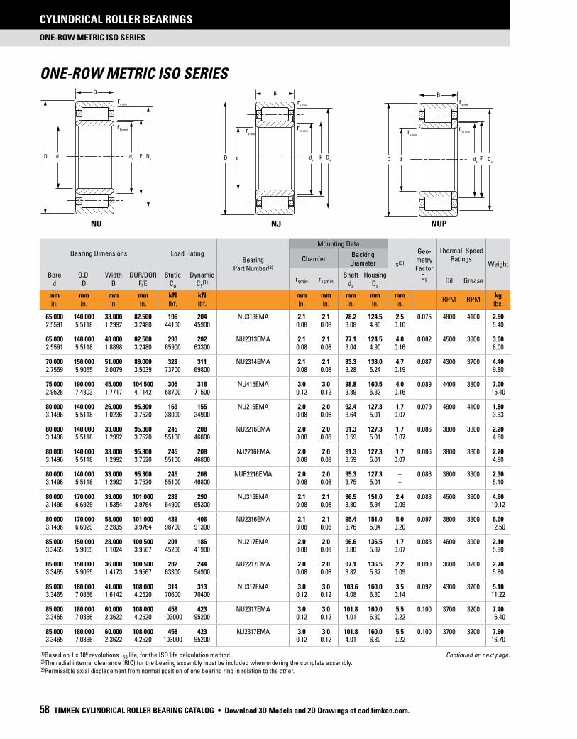
ONE-ROW METRIC ISO SERIES
CYLINDRICAL ROLLER BEARINGS
58 TIMKEN CYLINDRICAL ROLLER BEARING CATALOG
Bearing Dimensions Load RatingBearing
Part Number(2)
Mounting Data
s(3)
Geo-metry Factor
Cg
Thermal Speed Ratings
WeightChamfer
Backing Diameter
Bored
O.D.D
WidthB
DUR/DORF/E
StaticCo
DynamicC1
(1) rsmin r1sminShaft
ds
HousingDs
Oil Grease
mmin.
mmin.
mmin.
mmin.
kNlbf.
kNlbf.
mmin.
mmin.
mmin.
mmin.
mmin.
RPM RPMkglbs.
65.000 140.000 33.000 82.500 196 204 NU313EMA 2.1 2.1 78.2 124.5 2.5 0.075 4800 4100 2.502.5591 5.5118 1.2992 3.2480 44100 45900 0.08 0.08 3.08 4.90 0.10 5.40
65.000 140.000 48.000 82.500 293 282 NU2313EMA 2.1 2.1 77.1 124.5 4.0 0.082 4500 3900 3.602.5591 5.5118 1.8898 3.2480 65900 63300 0.08 0.08 3.04 4.90 0.16 8.00
70.000 150.000 51.000 89.000 328 311 NU2314EMA 2.1 2.1 83.3 133.0 4.7 0.087 4300 3700 4.402.7559 5.9055 2.0079 3.5039 73700 69800 0.08 0.08 3.28 5.24 0.19 9.80
75.000 190.000 45.000 104.500 305 318 NU415EMA 3.0 3.0 98.8 160.5 4.0 0.089 4400 3800 7.002.9528 7.4803 1.7717 4.1142 68700 71500 0.12 0.12 3.89 6.32 0.16 15.40
80.000 140.000 26.000 95.300 169 155 NU216EMA 2.0 2.0 92.4 127.3 1.7 0.079 4900 4100 1.803.1496 5.5118 1.0236 3.7520 38000 34900 0.08 0.08 3.64 5.01 0.07 3.63
80.000 140.000 33.000 95.300 245 208 NU2216EMA 2.0 2.0 91.3 127.3 1.7 0.086 3800 3300 2.203.1496 5.5118 1.2992 3.7520 55100 46800 0.08 0.08 3.59 5.01 0.07 4.80
80.000 140.000 33.000 95.300 245 208 NJ2216EMA 2.0 2.0 91.3 127.3 1.7 0.086 3800 3300 2.203.1496 5.5118 1.2992 3.7520 55100 46800 0.08 0.08 3.59 5.01 0.07 4.90
80.000 140.000 33.000 95.300 245 208 NUP2216EMA 2.0 2.0 95.3 127.3 – 0.086 3800 3300 2.303.1496 5.5118 1.2992 3.7520 55100 46800 0.08 0.08 3.75 5.01 – 5.10
80.000 170.000 39.000 101.000 289 290 NU316EMA 2.1 2.1 96.5 151.0 2.4 0.088 4500 3900 4.603.1496 6.6929 1.5354 3.9764 64900 65300 0.08 0.08 3.80 5.94 0.09 10.12
80.000 170.000 58.000 101.000 439 406 NU2316EMA 2.1 2.1 95.4 151.0 5.0 0.097 3800 3300 6.003.1496 6.6929 2.2835 3.9764 98700 91300 0.08 0.08 3.76 5.94 0.20 12.50
85.000 150.000 28.000 100.500 201 186 NU217EMA 2.0 2.0 96.6 136.5 1.7 0.083 4600 3900 2.103.3465 5.9055 1.1024 3.9567 45200 41900 0.08 0.08 3.80 5.37 0.07 5.80
85.000 150.000 36.000 100.500 282 244 NU2217EMA 2.0 2.0 97.1 136.5 2.2 0.090 3600 3200 2.703.3465 5.9055 1.4173 3.9567 63300 54900 0.08 0.08 3.82 5.37 0.09 5.80
85.000 180.000 41.000 108.000 314 313 NU317EMA 3.0 3.0 103.6 160.0 3.5 0.092 4300 3700 5.103.3465 7.0866 1.6142 4.2520 70600 70400 0.12 0.12 4.08 6.30 0.14 11.22
85.000 180.000 60.000 108.000 458 423 NU2317EMA 3.0 3.0 101.8 160.0 5.5 0.100 3700 3200 7.403.3465 7.0866 2.3622 4.2520 103000 95200 0.12 0.12 4.01 6.30 0.22 16.40
85.000 180.000 60.000 108.000 458 423 NJ2317EMA 3.0 3.0 101.8 160.0 5.5 0.100 3700 3200 7.603.3465 7.0866 2.3622 4.2520 103000 95200 0.12 0.12 4.01 6.30 0.22 16.70
ONE-ROW METRIC ISO SERIES
NU
dD
B
ds
Ds
F
rs min
r1s min
NJ
dD
B
ds
Ds
F
rs min
r1s minr
s min
NUP
d Ds
D
B
ds
F
rs min
r1s minr
s min
(1)Based on 1 x 10⁶ revolutions L10 life, for the ISO life calculation method. (2)The radial internal clearance (RIC) for the bearing assembly must be included when ordering the complete assembly. (3)Permissible axial displacement from normal position of one bearing ring in relation to the other.
Continued on next page.
• Download 3D Models and 2D Drawings at cad.timken.com.

ONE-ROW METRIC ISO SERIES
CYLINDRICAL ROLLER BEARINGS
TIMKEN CYLINDRICAL ROLLER BEARING CATALOG 59
Bearing Dimensions Load RatingBearing
Part Number(2)
Mounting Data
s(3)
Geo-metry Factor
Cg
Thermal Speed Ratings
WeightChamfer
Backing Diameter
Bored
O.D.D
WidthB
DUR/DORF/E
StaticCo
DynamicC1
(1) rsmin r1sminShaft
ds
HousingDs
Oil Grease
mmin.
mmin.
mmin.
mmin.
kNlbf.
kNlbf.
mmin.
mmin.
mmin.
mmin.
mmin.
RPM RPMkglbs.
90.000 160.000 30.000 107.000 225 206 NU218EMA 2.0 2.0 103.6 145.0 2.7 0.087 4400 3700 2.603.5433 6.2992 1.1811 4.2126 50500 46400 0.08 0.08 4.08 5.71 0.11 5.80
90.000 160.000 30.000 107.000 225 206 NJ218EMA 2.0 2.0 103.6 145.0 2.7 0.087 4400 3700 2.703.5433 6.2992 1.1811 4.2126 50500 46400 0.08 0.08 4.08 5.71 0.11 5.90
90.000 160.000 40.000 107.000 322 275 NU2218EMA 2.0 2.0 103.0 145.0 3.2 0.094 3600 3100 3.503.5433 6.2992 1.5748 4.2126 72400 61900 0.08 0.08 4.06 5.71 0.12 7.70
90.000 160.000 40.000 107.000 322 275 NJ2218EMA 2.0 2.0 102.9 145.0 3.2 0.094 3600 3100 3.603.5433 6.2992 1.5748 4.2126 72400 61900 0.08 0.08 4.05 5.71 0.12 7.90
90.000 160.000 40.000 107.000 322 275 NUP2218EMA 2.0 2.0 102.9 145.0 – 0.094 3600 3100 3.603.5433 6.2992 1.5748 4.2126 72400 61900 0.08 0.08 4.05 5.71 – 8.00
90.000 190.000 43.000 113.500 362 359 NU318EMA 3.0 3.0 107.9 169.5 2.5 0.096 4000 3500 6.103.5433 7.4803 1.6929 4.4685 81500 80700 0.12 0.12 4.25 6.67 0.10 13.40
90.000 190.000 43.000 113.500 362 359 NJ318EMA 3.0 3.0 107.9 169.5 2.5 0.096 4000 3500 6.203.5433 7.4803 1.6929 4.4685 81500 80700 0.12 0.12 4.25 6.67 0.10 13.60
90.000 190.000 64.000 113.500 544 497 NU2318EMA 3.0 3.0 106.8 169.5 5.0 0.106 3300 2900 9.103.5433 7.4803 2.5197 4.4685 122000 112000 0.12 0.12 4.20 6.67 0.20 20.00
90.000 190.000 64.000 113.500 544 497 NJ2318EMA 3.0 3.0 106.8 169.5 5.0 0.106 3300 2900 9.303.5433 7.4803 2.5197 4.4685 122000 112000 0.12 0.12 4.20 6.67 0.20 20.40
95.000 170.000 32.000 112.500 271 248 NU219EMA 2.1 2.1 109.1 154.5 1.8 0.092 4100 3500 3.103.7402 6.6929 1.2598 4.4291 60900 55800 0.08 0.08 4.30 6.08 0.07 6.90
95.000 170.000 32.000 112.500 271 248 NJ219EMA 2.1 2.1 109.1 154.5 1.8 0.092 4100 3500 3.203.7402 6.6929 1.2598 4.4291 60900 55800 0.08 0.08 4.30 6.08 0.07 7.00
95.000 170.000 43.000 112.500 378 324 NU2219EMA 2.1 2.1 108.1 154.5 3.5 0.099 3400 2900 4.203.7402 6.6929 1.6929 4.4291 84900 72800 0.08 0.08 4.26 6.08 0.14 9.30
95.000 170.000 43.000 112.500 378 324 NJ2219EMA 2.1 2.1 108.1 154.5 3.5 0.099 3400 2900 4.303.7402 6.6929 1.6929 4.4291 84900 72800 0.08 0.08 4.26 6.08 0.14 9.50
95.000 200.000 45.000 121.500 395 379 NU319EMA 3.0 3.0 115.3 177.5 3.0 0.101 3900 3400 7.103.7402 7.8740 1.7717 4.7835 88900 85300 0.12 0.12 4.54 6.99 0.12 15.70
95.000 200.000 45.000 121.500 395 379 NJ319EMA 3.0 3.0 115.3 177.5 3.0 0.101 3900 3400 7.303.7402 7.8740 1.7717 4.7835 88900 85300 0.12 0.12 4.54 6.99 0.12 16.00
N
dD
B
ds
Ds
E
rs min
rs min
r1s min
NF
ds
d Ds
D
B
E
rs min
rs min
r1s min
(1)Based on 1 x 10⁶ revolutions L10 life, for the ISO life calculation method. (2)The radial internal clearance (RIC) for the bearing assembly must be included when ordering the complete assembly. (3)Permissible axial displacement from normal position of one bearing ring in relation to the other.
Continued on next page.
Download 3D Models and 2D Drawings at cad.timken.com. •

ONE-ROW METRIC ISO SERIES
CYLINDRICAL ROLLER BEARINGS
60 TIMKEN CYLINDRICAL ROLLER BEARING CATALOG
ONE-ROW METRIC ISO SERIES – continued
NU
dD
B
ds
Ds
F
rs min
r1s min
NJ
dD
B
ds
Ds
F
rs min
r1s minr
s min
NUP
d Ds
D
B
ds
F
rs min
r1s minr
s min
(1)Based on 1 x 10⁶ revolutions L10 life, for the ISO life calculation method. (2)The radial internal clearance (RIC) for the bearing assembly must be included when ordering the complete assembly. (3)Permissible axial displacement from normal position of one bearing ring in relation to the other.
Continued on next page.
Bearing Dimensions Load RatingBearing
Part Number(2)
Mounting Data
s(3)
Geo-metry Factor
Cg
Thermal Speed Ratings
WeightChamfer
Backing Diameter
Bored
O.D.D
WidthB
DUR/DORF/E
StaticCo
DynamicC1
(1) rsmin r1sminShaft
ds
HousingDs
Oil Grease
mmin.
mmin.
mmin.
mmin.
kNlbf.
kNlbf.
mmin.
mmin.
mmin.
mmin.
mmin.
RPM RPMkglbs.
95.000 200.000 67.000 121.500 593 525 NU2319EMA 3.0 3.0 115.5 177.5 7.1 0.111 3100 2700 10.403.7402 7.8740 2.6378 4.7835 133000 118000 0.12 0.12 4.55 6.99 0.28 22.80
95.000 200.000 67.000 121.500 593 525 NJ2319EMA 3.0 3.0 115.5 177.5 7.1 0.111 3100 2700 10.603.7402 7.8740 2.6378 4.7835 133000 118000 0.12 0.12 4.55 6.99 0.28 23.30
100.000 180.000 34.000 119.000 311 280 NU220EMA 2.1 2.1 115.0 163.0 2.3 0.097 3900 3300 3.803.9370 7.0866 1.3386 4.6850 70000 63000 0.08 0.08 4.53 6.42 0.09 8.40
100.000 180.000 34.000 119.000 311 280 NJ220EMA 2.1 2.1 115.0 163.0 2.3 0.097 3900 3300 3.903.9370 7.0866 1.3386 4.6850 70000 63000 0.08 0.08 4.53 6.42 0.09 8.60
100.000 180.000 46.000 119.000 451 377 NU2220EMA 2.1 2.1 115.0 163.0 3.3 0.105 3100 2800 5.203.9370 7.0866 1.8110 4.6850 101000 84800 0.08 0.08 4.53 6.42 0.13 11.40
100.000 180.000 46.000 119.000 451 377 NJ2220EMA 2.1 2.1 115.0 163.0 3.3 0.105 3100 2800 5.303.9370 7.0866 1.8110 4.6850 101000 84800 0.08 0.08 4.53 6.42 0.13 11.60
100.000 215.000 47.000 127.500 442 437 NU320EMA 3.0 3.0 120.7 191.5 3.0 0.104 3600 3200 8.603.9370 8.4646 1.8504 5.0197 99400 98200 0.12 0.12 4.75 7.54 0.12 19.00
100.000 215.000 47.000 127.500 442 437 NJ320EMA 3.0 3.0 120.7 191.5 3.0 0.104 3600 3200 8.803.9370 8.4646 1.8504 5.0197 99400 98200 0.12 0.12 4.75 7.54 0.12 19.40
100.000 215.000 73.000 127.500 737 658 NU2320EMA 3.0 3.0 120.4 191.5 5.2 0.117 2700 2400 13.403.9370 8.4646 2.8740 5.0197 166000 148000 0.12 0.12 4.74 7.54 0.20 29.50
100.000 215.000 73.000 127.500 737 658 NJ2320EMA 3.0 3.0 120.4 191.5 5.2 0.117 2700 2400 13.703.9370 8.4646 2.8740 5.0197 166000 148000 0.12 0.12 4.74 7.54 0.20 30.10
110.000 200.000 38.000 132.500 374 331 NU222EMA 2.1 2.1 128.5 180.5 2.5 0.104 3600 3100 5.404.3307 7.8740 1.4961 5.2165 84000 74400 0.08 0.08 5.06 7.11 0.10 11.90
110.000 200.000 38.000 132.500 374 331 NJ222EMA 2.1 2.1 128.5 180.5 2.5 0.104 3600 3100 5.504.3307 7.8740 1.4961 5.2165 84000 74400 0.08 0.08 5.06 7.11 0.10 12.10
110.000 200.000 53.000 132.500 527 436 NU2222EMA 2.1 2.1 126.8 180.5 4.1 0.113 3000 2700 7.504.3307 7.8740 2.0866 5.2165 118000 98000 0.08 0.08 4.99 7.11 0.16 16.50
110.000 200.000 53.000 132.500 527 436 NJ2222EMA 2.1 2.1 126.8 180.5 4.1 0.113 3000 2700 7.604.3307 7.8740 2.0866 5.2165 118000 98000 0.08 0.08 4.99 7.11 0.16 16.80
110.000 240.000 50.000 143.000 546 519 NU322EMA 3.0 3.0 136.2 211.0 3.0 0.114 3100 2800 11.604.3307 9.4488 1.9685 5.6299 123000 11700 0.12 0.12 5.36 8.31 0.12 25.40
• Download 3D Models and 2D Drawings at cad.timken.com.

ONE-ROW METRIC ISO SERIES
CYLINDRICAL ROLLER BEARINGS
TIMKEN CYLINDRICAL ROLLER BEARING CATALOG 61
N
dD
B
ds
Ds
E
rs min
rs min
r1s min
NF
ds
d Ds
D
B
E
rs min
rs min
r1s min
Bearing Dimensions Load RatingBearing
Part Number(2)
Mounting Data
s(3)
Geo-metry Factor
Cg
Thermal Speed Ratings
WeightChamfer
Backing Diameter
Bored
O.D.D
WidthB
DUR/DORF/E
StaticCo
DynamicC1
(1) rsmin r1sminShaft
ds
HousingDs
Oil Grease
mmin.
mmin.
mmin.
mmin.
kNlbf.
kNlbf.
mmin.
mmin.
mmin.
mmin.
mmin.
RPM RPMkglbs.
110.000 240.000 50.000 143.000 546 519 NJ322EMA 3.0 3.0 136.2 211.0 3.0 0.114 3100 2800 11.804.3307 9.4488 1.9685 5.6299 123000 11700 0.12 0.12 5.36 8.31 0.12 25.90
110.000 240.000 80.000 143.000 891 768 NU2322EMA 3.0 3.0 134.6 211.0 6.4 0.128 2400 2100 18.604.3307 9.4488 3.1496 5.6299 200000 173000 0.12 0.12 5.30 8.31 0.25 40.90
110.000 240.000 80.000 143.000 891 768 NJ2322EMA 3.0 3.0 134.6 211.0 6.4 0.128 2400 2100 19.204.3307 9.4488 3.1496 5.6299 200000 173000 0.12 0.12 5.30 8.31 0.25 42.10
120.000 180.000 28.000 135.000 202 158 NU1024MA 2.0 1.1 131.2 165.0 3.8 0.096 3600 2900 2.604.7244 7.0866 1.1024 5.3150 45300 35600 0.08 0.04 5.17 6.50 0.15 5.60
120.000 215.000 40.000 143.500 431 379 NU224EMA 2.1 2.1 138.0 195.5 2.1 0.111 3400 2900 6.504.7244 8.4646 1.5748 5.6496 97000 85300 0.08 0.08 5.43 7.70 0.08 14.30
120.000 215.000 40.000 143.500 431 379 NJ224EMA 2.1 2.1 138.0 195.5 2.1 0.111 3400 2900 6.604.7244 8.4646 1.5748 5.6496 97000 85300 0.08 0.08 5.43 7.70 0.08 14.50
120.000 215.000 58.000 143.500 630 514 NU2224EMA 2.1 2.1 137.4 195.5 4.6 0.121 2700 2400 9.404.7244 8.4646 2.2835 5.6496 142000 116000 0.08 0.08 5.41 7.70 0.18 20.80
120.000 215.000 58.000 143.500 630 514 NJ2224EMA 2.1 2.1 137.4 195.5 4.6 0.121 2700 2400 9.604.7244 8.4646 2.2835 5.6496 142000 116000 0.08 0.08 5.41 7.70 0.18 21.20
120.000 260.000 55.000 154.000 614 594 NU324EMA 3.0 3.0 147.0 230.0 3.8 0.120 2900 2500 14.704.7244 10.2362 2.1654 6.0630 138000 134000 0.12 0.12 5.79 9.06 0.15 32.30
120.000 260.000 55.000 154.000 614 594 NJ324EMA 3.0 3.0 147.0 230.0 3.8 0.120 2900 2500 15.004.7244 10.2362 2.1654 6.0630 138000 134000 0.12 0.12 5.79 9.06 0.15 32.90
120.000 260.000 86.000 154.000 1040 902 NU2324EMA 3.0 3.0 145.9 230.0 6.3 0.136 2100 1900 23.104.7244 10.2362 3.3858 6.0630 233000 203000 0.12 0.12 5.74 9.06 0.25 50.90
120.000 260.000 86.000 154.000 1040 902 NJ2324EMA 3.0 3.0 145.9 230.0 6.3 0.136 2100 1900 23.604.7244 10.2362 3.3858 6.0630 233000 203000 0.12 0.12 5.74 9.06 0.25 52.00
130.000 200.000 33.000 148.000 251 197 NU1026MA 2.0 1.1 142.6 182.0 2.2 0.104 3500 2900 7.205.1181 7.8740 1.2992 5.8268 56500 44300 0.08 0.04 5.61 7.17 0.09 15.80
130.000 230.000 40.000 153.500 464 411 NU226EMA 3.0 3.0 148.0 209.5 2.2 0.115 3100 2700 7.205.1181 9.0551 1.5748 6.0433 104000 92300 0.12 0.12 5.83 8.25 0.09 15.80
130.000 230.000 40.000 153.500 464 411 NJ226EMA 3.0 3.0 148.0 209.5 2.2 0.115 3100 2700 7.305.1181 9.0551 1.5748 6.0433 104000 92300 0.12 0.12 5.83 8.25 0.09 16.10
(1)Based on 1 x 10⁶ revolutions L10 life, for the ISO life calculation method. (2)The radial internal clearance (RIC) for the bearing assembly must be included when ordering the complete assembly. (3)Permissible axial displacement from normal position of one bearing ring in relation to the other.
Continued on next page.
Download 3D Models and 2D Drawings at cad.timken.com. •

ONE-ROW METRIC ISO SERIES
CYLINDRICAL ROLLER BEARINGS
62 TIMKEN CYLINDRICAL ROLLER BEARING CATALOG
ONE-ROW METRIC ISO SERIES – continued
NU
dD
B
ds
Ds
F
rs min
r1s min
NJ
dD
B
ds
Ds
F
rs min
r1s minr
s min
NUP
d Ds
D
B
ds
F
rs min
r1s minr
s min
(1)Based on 1 x 10⁶ revolutions L10 life, for the ISO life calculation method. (2)The radial internal clearance (RIC) for the bearing assembly must be included when ordering the complete assembly. (3)Permissible axial displacement from normal position of one bearing ring in relation to the other.
Continued on next page.
Bearing Dimensions Load RatingBearing
Part Number(2)
Mounting Data
s(3)
Geo-metry Factor
Cg
Thermal Speed Ratings
WeightChamfer
Backing Diameter
Bored
O.D.D
WidthB
DUR/DORF/E
StaticCo
DynamicC1
(1) rsmin r1sminShaft
ds
HousingDs
Oil Grease
mmin.
mmin.
mmin.
mmin.
kNlbf.
kNlbf.
mmin.
mmin.
mmin.
mmin.
mmin.
RPM RPMkglbs.
130.000 230.000 64.000 153.500 750 603 NU2226EMA 3.0 3.0 146.8 209.5 5.0 0.129 2400 2200 11.505.1181 9.0551 2.5197 6.0433 169000 135000 0.12 0.12 5.78 8.25 0.20 25.40
130.000 230.000 64.000 153.500 750 603 NJ2226EMA 3.0 3.0 146.8 209.5 5.0 0.129 2400 2200 11.805.1181 9.0551 2.5197 6.0433 169000 135000 0.12 0.12 5.78 8.25 0.20 25.90
130.000 280.000 58.000 167.000 753 701 NU326EMA 4.0 4.0 159.7 247.0 3.7 0.108 2500 2200 18.105.1181 11.0236 2.2835 6.5748 169000 158000 0.16 0.16 6.29 9.72 0.14 39.70
130.000 280.000 58.000 167.000 753 701 NJ326EMA 4.0 4.0 159.7 247.0 3.7 0.108 2500 2200 18.505.1181 11.0236 2.2835 6.5748 169000 158000 0.16 0.16 6.29 9.72 0.14 40.70
130.000 280.000 93.000 167.000 1240 1040 NU2326EMA 4.0 4.0 158.1 247.0 7.6 0.122 1900 1700 29.305.1181 11.0236 3.6614 6.5748 278000 235000 0.16 0.16 6.22 9.72 0.30 64.40
130.000 280.000 93.000 167.000 1240 1040 NJ2326EMA 4.0 4.0 158.1 247.0 7.6 0.122 1900 1700 29.805.1181 11.0236 3.6614 6.5748 278000 235000 0.16 0.16 6.22 9.72 0.30 65.50
140.000 210.000 33.000 158.000 263 201 NU1028MA 2.0 1.1 152.9 192.0 3.8 0.108 3300 2700 4.005.5118 8.2677 1.2992 6.2205 59200 45200 0.08 0.04 6.02 7.56 0.15 8.90
140.000 250.000 42.000 169.000 526 443 NU228EMA 3.0 3.0 162.4 225.0 2.1 0.124 2900 2500 9.205.5118 9.8425 1.6535 6.6535 118000 99500 0.12 0.12 6.39 8.86 0.08 20.30
140.000 250.000 42.000 169.000 526 443 NJ228EMA 3.0 3.0 162.4 225.0 2.1 0.124 2900 2500 9.405.5118 9.8425 1.6535 6.6535 118000 99500 0.12 0.12 6.39 8.86 0.08 20.70
140.000 250.000 68.000 169.000 850 650 NU2228EMA 3.0 3.0 160.1 225.0 5.0 0.138 2200 2000 14.805.5118 9.8425 2.6772 6.6535 191000 146000 0.12 0.12 6.30 8.86 0.20 32.50
140.000 250.000 68.000 169.000 850 650 NJ2228EMA 3.0 3.0 160.1 225.0 5.0 0.138 2200 2000 15.105.5118 9.8425 2.6772 6.6535 191000 146000 0.12 0.12 6.30 8.86 0.20 33.20
140.000 300.000 62.000 180.000 837 771 NU328EMA 4.0 4.0 174.2 264.0 5.2 0.114 2300 2000 22.105.5118 11.8110 2.4409 7.0866 188000 173000 0.16 0.16 6.86 10.39 0.20 48.50
140.000 300.000 62.000 180.000 837 771 NJ328EMA 4.0 4.0 174.2 264.0 5.2 0.114 2300 2000 22.505.5118 11.8110 2.4409 7.0866 188000 173000 0.16 0.16 6.86 10.39 0.20 49.50
140.000 300.000 102.000 180.000 1420 1180 NU2328EMA 4.0 4.0 171.3 264.0 9.7 0.129 1700 1500 36.105.5118 11.8110 4.0157 7.0866 319000 265000 0.16 0.16 6.74 10.39 0.38 79.40
140.000 300.000 102.000 180.000 1420 1180 NJ2328EMA 4.0 4.0 171.3 264.0 9.7 0.129 1700 1500 36.805.5118 11.8110 4.0157 7.0866 319000 265000 0.16 0.16 6.74 10.39 0.38 81.00
• Download 3D Models and 2D Drawings at cad.timken.com.

ONE-ROW METRIC ISO SERIES
CYLINDRICAL ROLLER BEARINGS
TIMKEN CYLINDRICAL ROLLER BEARING CATALOG 63
N
dD
B
ds
Ds
E
rs min
rs min
r1s min
NF
ds
d Ds
D
B
E
rs min
rs min
r1s min
Bearing Dimensions Load RatingBearing
Part Number(2)
Mounting Data
s(3)
Geo-metry Factor
Cg
Thermal Speed Ratings
WeightChamfer
Backing Diameter
Bored
O.D.D
WidthB
DUR/DORF/E
StaticCo
DynamicC1
(1) rsmin r1sminShaft
ds
HousingDs
Oil Grease
mmin.
mmin.
mmin.
mmin.
kNlbf.
kNlbf.
mmin.
mmin.
mmin.
mmin.
mmin.
RPM RPMkglbs.
150.000 225.000 35.000 169.500 309 231 NU1030MA 2.1 1.5 164.6 205.5 4.9 0.115 3100 2500 4.905.9055 8.8583 1.3780 6.6732 69500 51900 0.08 0.06 6.48 8.09 0.19 10.80
150.000 270.000 45.000 182.000 607 506 NU230EMA 3.0 3.0 176.9 242.0 4.0 0.109 2600 2300 11.605.9055 10.6299 1.7717 7.1654 137000 114000 0.12 0.12 6.96 9.53 0.16 25.60
150.000 270.000 45.000 182.000 607 506 NJ230EMA 3.0 3.0 176.9 242.0 4.0 0.109 2600 2300 12.005.9055 10.6299 1.7717 7.1654 137000 114000 0.12 0.12 6.96 9.53 0.16 26.30
150.000 270.000 45.000 182.000 607 506 NUP230EMA 3.0 3.0 176.9 242.0 – 0.109 2600 2300 12.105.9055 10.6299 1.7717 7.1654 137000 114000 0.12 0.12 6.96 9.53 – 26.60
150.000 270.000 73.000 182.000 998 752 NU2230EMA 3.0 3.0 173.5 242.0 6.0 0.123 2000 1800 18.605.9055 10.6299 2.8740 7.1654 224000 169000 0.12 0.12 6.83 9.53 0.24 40.90
150.000 270.000 73.000 182.000 998 752 NJ2230EMA 3.0 3.0 173.5 242.0 6.0 0.123 2000 1800 18.905.9055 10.6299 2.8740 7.1654 224000 169000 0.12 0.12 6.83 9.53 0.24 41.36
150.000 270.000 73.000 242.000 998 752 N2230EMB 3.0 3.0 182.0 250.5 6.0 0.123 2000 1800 18.405.9055 10.6299 2.8740 9.5276 224000 169000 0.12 0.12 7.17 9.86 0.24 40.40
150.000 320.000 65.000 193.000 951 870 NU330EMA 4.0 4.0 185.7 283.0 4.0 0.120 2100 1900 26.205.9055 12.5984 2.5591 7.5984 214000 196000 0.16 0.16 7.31 11.14 0.16 57.70
150.000 320.000 65.000 193.000 951 870 NJ330EMA 4.0 4.0 185.7 283.0 4.0 0.120 2100 1900 26.705.9055 12.5984 2.5591 7.5984 214000 196000 0.16 0.16 7.31 11.14 0.16 58.80
150.000 320.000 108.000 193.000 1620 1330 NU2330EMA 4.0 4.0 182.7 283.0 9.0 0.136 1600 1400 43.605.9055 12.5984 4.2520 7.5984 364000 299000 0.16 0.16 7.19 11.14 0.35 95.80
150.000 320.000 108.000 193.000 1620 1330 NJ2330EMA 4.0 4.0 182.7 283.0 9.0 0.136 1600 1400 44.405.9055 12.5984 4.2520 7.5984 364000 299000 0.16 0.16 7.19 11.14 0.35 97.70
160.000 240.000 38.000 180.000 367 276 NU1032MA 2.1 1.5 173.9 220.0 4.4 0.121 3000 2400 5.906.2992 9.4488 1.4961 7.0866 82500 62000 0.08 0.06 6.85 8.66 0.17 13.00
160.000 290.000 48.000 195.000 695 572 NU232EMA 3.0 3.0 189.6 259.0 4.2 0.115 2400 2100 14.506.2992 11.4173 1.8898 7.6772 156000 129000 0.12 0.12 7.46 10.20 0.17 31.80
160.000 290.000 48.000 195.000 695 572 NJ232EMA 3.0 3.0 189.6 259.0 4.2 0.115 2400 2100 14.706.2992 11.4173 1.8898 7.6772 156000 129000 0.12 0.12 7.46 10.20 0.17 32.40
160.000 290.000 48.000 195.000 695 572 NUP232EMA 3.0 3.0 189.6 259.0 – 0.115 2400 2100 15.006.2992 11.4173 1.8898 7.6772 156000 129000 0.12 0.12 7.46 10.20 – 33.00
(1)Based on 1 x 10⁶ revolutions L10 life, for the ISO life calculation method. (2)The radial internal clearance (RIC) for the bearing assembly must be included when ordering the complete assembly. (3)Permissible axial displacement from normal position of one bearing ring in relation to the other.
Continued on next page.
Download 3D Models and 2D Drawings at cad.timken.com. •

ONE-ROW METRIC ISO SERIES
CYLINDRICAL ROLLER BEARINGS
64 TIMKEN CYLINDRICAL ROLLER BEARING CATALOG
ONE-ROW METRIC ISO SERIES – continued
NU
dD
B
ds
Ds
F
rs min
r1s min
NJ
dD
B
ds
Ds
F
rs min
r1s minr
s min
NUP
d Ds
D
B
ds
F
rs min
r1s minr
s min
(1)Based on 1 x 10⁶ revolutions L10 life, for the ISO life calculation method. (2)The radial internal clearance (RIC) for the bearing assembly must be included when ordering the complete assembly. (3)Permissible axial displacement from normal position of one bearing ring in relation to the other.
Continued on next page.
Bearing Dimensions Load RatingBearing
Part Number(2)
Mounting Data
s(3)
Geo-metry Factor
Cg
Thermal Speed Ratings
WeightChamfer
Backing Diameter
Bored
O.D.D
WidthB
DUR/DORF/E
StaticCo
DynamicC1
(1) rsmin r1sminShaft
ds
HousingDs
Oil Grease
mmin.
mmin.
mmin.
mmin.
kNlbf.
kNlbf.
mmin.
mmin.
mmin.
mmin.
mmin.
RPM RPMkglbs.
160.000 290.000 80.000 193.000 1210 919 NU2232EMA 3.0 3.0 183.6 261.0 4.5 0.130 1700 1600 23.806.2992 11.4173 3.1496 7.5984 271000 207000 0.12 0.12 7.23 10.28 0.18 52.40
160.000 290.000 80.000 193.000 1210 919 NJ2232EMA 3.0 3.0 183.6 261.0 4.5 0.130 1700 1600 24.306.2992 11.4173 3.1496 7.5984 271000 207000 0.12 0.12 7.23 10.28 0.18 53.50
160.000 340.000 68.000 204.000 1090 985 NU332EMA 4.0 4.0 197.3 300.0 5.5 0.126 1900 1700 31.106.2992 13.3858 2.6772 8.0315 244000 221000 0.16 0.16 7.77 11.81 0.22 68.40
160.000 340.000 68.000 204.000 1090 985 NJ332EMA 4.0 4.0 197.3 300.0 5.5 0.126 1900 1700 31.606.2992 13.3858 2.6772 8.0315 244000 221000 0.16 0.16 7.77 11.81 0.22 69.50
160.000 340.000 114.000 204.000 1840 1500 NU2332EMA 4.0 4.0 194.0 300.0 10.0 0.143 1400 1300 52.206.2992 13.3858 4.4882 8.0315 413000 337000 0.16 0.16 7.64 11.81 0.39 114.80
160.000 340.000 114.000 204.000 1840 1500 NJ2332EMA 4.0 4.0 194.0 300.0 10.0 0.143 1400 1300 53.106.2992 13.3858 4.4882 8.0315 413000 337000 0.16 0.16 7.64 11.81 0.39 116.80
170.000 260.000 42.000 193.000 425 321 NU1034MA 2.1 2.1 186.3 237.0 4.9 0.107 2800 2300 8.006.6929 10.2362 1.6535 7.5984 95600 72200 0.08 0.08 7.33 9.33 0.19 17.70
170.000 260.000 67.000 191.000 1080 722 NU3034EMA 2.1 2.1 185.2 241.0 4.4 0.131 1500 1300 8.006.6929 10.2362 2.6378 7.5197 243000 162000 0.08 0.08 7.29 9.49 0.17 17.70
170.000 310.000 52.000 207.000 822 685 NU234EMA 4.0 4.0 201.6 279.0 4.4 0.122 2200 1900 17.606.6929 12.2047 2.0472 8.1496 185000 154000 0.16 0.16 7.94 10.98 0.17 38.70
170.000 310.000 52.000 207.000 822 685 NJ234EMA 4.0 4.0 201.6 279.0 4.4 0.122 2200 1900 17.906.6929 12.2047 2.0472 8.1496 185000 154000 0.16 0.16 7.94 10.98 0.17 39.40
170.000 310.000 86.000 205.000 1420 1100 NU2234EMA 4.0 4.0 196.9 281.0 4.5 0.138 1600 1400 28.706.6929 12.2047 3.3858 8.0709 320000 246000 0.16 0.16 7.75 11.06 0.18 63.20
170.000 310.000 86.000 205.000 1420 1100 NJ2234EMA 4.0 4.0 196.9 281.0 4.5 0.138 1600 1400 29.306.6929 12.2047 3.3858 8.0709 320000 246000 0.16 0.16 7.75 11.06 0.18 64.50
170.000 360.000 72.000 218.000 1160 1050 NU334EMA 4.0 4.0 210.5 318.0 6.4 0.131 1800 1600 36.906.6929 14.1732 2.8346 8.5827 261000 236000 0.16 0.16 8.29 12.52 0.25 81.18
170.000 360.000 72.000 218.000 1160 1050 NJ334EMA 4.0 4.0 210.5 318.0 6.4 0.131 1800 1600 37.506.6929 14.1732 2.8346 8.5827 261000 236000 0.16 0.16 8.29 12.52 0.25 82.50
170.000 360.000 120.000 216.000 2110 1710 NU2334EMA 4.0 4.0 205.7 320.0 10.3 0.150 1300 1200 61.906.6929 14.1732 4.7244 8.5039 474000 385000 0.16 0.16 8.10 12.60 0.41 136.20
• Download 3D Models and 2D Drawings at cad.timken.com.

ONE-ROW METRIC ISO SERIES
CYLINDRICAL ROLLER BEARINGS
TIMKEN CYLINDRICAL ROLLER BEARING CATALOG 65
N
dD
B
ds
Ds
E
rs min
rs min
r1s min
NF
ds
d Ds
D
B
E
rs min
rs min
r1s min
Bearing Dimensions Load RatingBearing
Part Number(2)
Mounting Data
s(3)
Geo-metry Factor
Cg
Thermal Speed Ratings
WeightChamfer
Backing Diameter
Bored
O.D.D
WidthB
DUR/DORF/E
StaticCo
DynamicC1
(1) rsmin r1sminShaft
ds
HousingDs
Oil Grease
mmin.
mmin.
mmin.
mmin.
kNlbf.
kNlbf.
mmin.
mmin.
mmin.
mmin.
mmin.
RPM RPMkglbs.
170.000 360.000 120.000 216.000 2110 1710 NJ2334EMA 4.0 4.0 205.7 320.0 10.3 0.150 1300 1200 63.006.6929 14.1732 4.7244 8.5039 474000 385000 0.16 0.16 8.10 12.60 0.41 138.50
180.000 280.000 46.000 205.000 500 386 NU1036MA 2.1 2.1 198.9 255.0 6.1 0.112 2600 2100 10.307.0866 11.0236 1.8110 8.0709 112000 86800 0.08 0.08 7.83 10.04 0.24 22.80
180.000 320.000 52.000 217.000 874 711 NU236EMA 4.0 4.0 211.6 289.0 4.4 0.126 2000 1800 18.307.0866 12.5984 2.0472 8.5433 196000 160000 0.16 0.16 8.33 11.38 0.17 40.40
180.000 320.000 52.000 217.000 874 711 NJ236EMA 4.0 4.0 211.6 289.0 4.4 0.126 2000 1800 18.707.0866 12.5984 2.0472 8.5433 196000 160000 0.16 0.16 8.33 11.38 0.17 41.10
180.000 320.000 86.000 215.000 1520 1140 NU2236EMA 4.0 4.0 206.0 291.0 5.5 0.143 1400 1300 30.607.0866 12.5984 3.3858 8.4646 342000 256000 0.16 0.16 8.11 11.46 0.22 67.32
180.000 320.000 86.000 215.000 1520 1140 NJ2236EMA 4.0 4.0 206.0 291.0 5.5 0.143 1400 1300 31.207.0866 12.5984 3.3858 8.4646 342000 256000 0.16 0.16 8.11 11.46 0.22 68.60
180.000 380.000 75.000 231.000 1290 1150 NU336EMA 4.0 4.0 223.2 335.0 6.5 0.137 1600 1500 42.607.0866 14.9606 2.9528 9.0945 290000 258000 0.16 0.16 8.79 13.19 0.26 93.60
180.000 380.000 75.000 231.000 1290 1150 NJ336EMA 4.0 4.0 223.2 335.0 6.5 0.137 1600 1500 43.407.0866 14.9606 2.9528 9.0945 290000 258000 0.16 0.16 8.79 13.19 0.26 95.50
180.000 380.000 126.000 227.000 2250 1860 NU2336EMA 4.0 4.0 215.7 339.0 8.7 0.154 1200 1100 70.907.0866 14.9606 4.9606 8.9370 506000 419000 0.16 0.16 8.49 13.35 0.34 155.90
180.000 380.000 126.000 227.000 2250 1860 NJ2336EMA 4.0 4.0 215.7 339.0 8.7 0.154 1200 1100 72.107.0866 14.9606 4.9606 8.9370 506000 419000 0.16 0.16 8.49 13.35 0.34 158.70
190.000 290.000 46.000 215.000 525 396 NU1038MA 2.1 2.1 207.9 265.0 6.1 0.116 2400 2000 10.707.4803 11.4173 1.8110 8.4646 118000 89100 0.08 0.08 8.19 10.43 0.24 23.50
190.000 340.000 55.000 230.000 960 777 NU238EMA 4.0 4.0 224.2 306.0 4.5 0.132 1900 1600 22.207.4803 13.3858 2.1654 9.0551 216000 175000 0.16 0.16 8.83 12.05 0.18 48.80
190.000 340.000 55.000 230.000 960 777 NJ238EMA 4.0 4.0 224.2 306.0 4.5 0.132 1900 1600 22.607.4803 13.3858 2.1654 9.0551 216000 175000 0.16 0.16 8.83 12.05 0.18 49.60
190.000 340.000 92.000 228.000 1680 1250 NU2238EMA 4.0 4.0 219.0 308.0 7.0 0.149 1300 1200 39.007.4803 13.3858 3.6220 8.9764 377000 281000 0.16 0.16 8.62 12.13 0.28 85.80
190.000 340.000 92.000 228.000 1680 1250 NJ2238EMA 4.0 4.0 219.0 308.0 7.0 0.149 1300 1200 37.807.4803 13.3858 3.6220 8.9764 377000 281000 0.16 0.16 8.62 12.13 0.28 83.20
(1)Based on 1 x 10⁶ revolutions L10 life, for the ISO life calculation method. (2)The radial internal clearance (RIC) for the bearing assembly must be included when ordering the complete assembly. (3)Permissible axial displacement from normal position of one bearing ring in relation to the other.
Continued on next page.
Download 3D Models and 2D Drawings at cad.timken.com. •

ONE-ROW METRIC ISO SERIES
CYLINDRICAL ROLLER BEARINGS
66 TIMKEN CYLINDRICAL ROLLER BEARING CATALOG
ONE-ROW METRIC ISO SERIES – continued
NU
dD
B
ds
Ds
F
rs min
r1s min
NJ
dD
B
ds
Ds
F
rs min
r1s minr
s min
NUP
d Ds
D
B
ds
F
rs min
r1s minr
s min
(1)Based on 1 x 10⁶ revolutions L10 life, for the ISO life calculation method. (2)The radial internal clearance (RIC) for the bearing assembly must be included when ordering the complete assembly. (3)Permissible axial displacement from normal position of one bearing ring in relation to the other.
Continued on next page.
Bearing Dimensions Load RatingBearing
Part Number(2)
Mounting Data
s(3)
Geo-metry Factor
Cg
Thermal Speed Ratings
WeightChamfer
Backing Diameter
Bored
O.D.D
WidthB
DUR/DORF/E
StaticCo
DynamicC1
(1) rsmin r1sminShaft
ds
HousingDs
Oil Grease
mmin.
mmin.
mmin.
mmin.
kNlbf.
kNlbf.
mmin.
mmin.
mmin.
mmin.
mmin.
RPM RPMkglbs.
190.000 400.000 78.000 245.000 1500 1300 NU338EMA 5.0 5.0 236.5 353.0 6.0 0.145 1500 1300 49.407.4803 15.7480 3.0709 9.6457 337000 292000 0.20 0.20 9.31 13.90 0.24 108.70
190.000 400.000 78.000 245.000 1500 1300 NJ338EMA 5.0 5.0 236.5 353.0 6.0 0.145 1500 1300 50.207.4803 15.7480 3.0709 9.6457 337000 292000 0.20 0.20 9.31 13.90 0.24 110.50
190.000 400.000 132.000 240.000 2500 2060 NU2338EMA 5.0 5.0 227.6 360.0 9.8 0.161 1100 1000 80.307.4803 15.7480 5.1969 9.4488 561000 464000 0.20 0.20 8.96 14.17 0.39 176.60
190.000 400.000 132.000 240.000 2500 2060 NJ2338EMA 5.0 5.0 227.6 360.0 9.8 0.161 1100 1000 81.807.4803 15.7480 5.1969 9.4488 561000 464000 0.20 0.20 8.96 14.17 0.39 179.90
200.000 310.000 51.000 229.000 596 440 NU1040MA 2.1 2.1 221.1 281.0 6.5 0.122 2300 1900 14.007.8740 12.2047 2.0079 9.0157 134000 98800 0.08 0.08 8.70 11.06 0.26 30.70
200.000 360.000 58.000 243.000 1090 870 NU240EMA 4.0 4.0 236.9 323.0 4.7 0.137 1700 1500 26.507.8740 14.1732 2.2835 9.5669 245000 196000 0.16 0.16 9.33 12.72 0.19 58.30
200.000 360.000 58.000 243.000 1090 870 NJ240EMA 4.0 4.0 236.9 323.0 4.7 0.137 1700 1500 27.007.8740 14.1732 2.2835 9.5669 245000 196000 0.16 0.16 9.33 12.72 0.19 59.40
200.000 360.000 98.000 241.000 1920 1410 NU2240EMA 4.0 4.0 231.5 325.0 7.0 0.156 1200 1100 44.407.8740 14.1732 3.8583 9.4882 431000 316000 0.16 0.16 9.11 12.80 0.28 97.70
200.000 360.000 98.000 241.000 1920 1410 NJ2240EMA 4.0 4.0 231.5 325.0 7.0 0.156 1200 1100 45.207.8740 14.1732 3.8583 9.4882 431000 316000 0.16 0.16 9.11 12.80 0.28 99.50
200.000 420.000 80.000 258.000 1580 1360 NU340EMA 5.0 5.0 249.9 370.0 7.0 0.150 1300 1200 55.807.8740 16.5354 3.1496 10.1575 354000 306000 0.20 0.20 9.84 14.57 0.28 122.70
200.000 420.000 80.000 258.000 1580 1360 NJ340EMA 5.0 5.0 249.9 370.0 7.0 0.150 1300 1200 56.707.8740 16.5354 3.1496 10.1575 354000 306000 0.20 0.20 9.84 14.57 0.28 124.70
200.000 420.000 138.000 253.000 2760 2250 NU2340EMA 5.0 5.0 240.7 377.0 9.2 0.167 1000 940 93.207.8740 16.5354 5.4331 9.9606 619000 505000 0.20 0.20 9.48 14.84 0.36 205.00
200.000 420.000 138.000 253.000 2760 2250 NJ2340EMA 5.0 5.0 240.7 377.0 9.2 0.167 1000 940 94.807.8740 16.5354 5.4331 9.9606 619000 505000 0.20 0.20 9.48 14.84 0.36 208.70
220.000 340.000 56.000 250.000 765 565 NU1044MA 3.0 3.0 242.6 310.0 8.4 0.132 2000 1700 18.408.6614 13.3858 2.2047 9.8425 172000 127000 0.12 0.12 9.55 12.20 0.33 40.40
220.000 340.000 56.000 250.000 765 565 NJ1044MA 3.0 3.0 242.6 310.0 8.4 0.132 2000 1700 18.908.6614 13.3858 2.2047 9.8425 172000 127000 0.12 0.12 9.55 12.20 0.33 41.60
• Download 3D Models and 2D Drawings at cad.timken.com.

ONE-ROW METRIC ISO SERIES
CYLINDRICAL ROLLER BEARINGS
TIMKEN CYLINDRICAL ROLLER BEARING CATALOG 67
Bearing Dimensions Load RatingBearing
Part Number(2)
Mounting Data
s(3)
Geo-metry Factor
Cg
Thermal Speed Ratings
WeightChamfer
Backing Diameter
Bored
O.D.D
WidthB
DUR/DORF/E
StaticCo
DynamicC1
(1) rsmin r1sminShaft
ds
HousingDs
Oil Grease
mmin.
mmin.
mmin.
mmin.
kNlbf.
kNlbf.
mmin.
mmin.
mmin.
mmin.
mmin.
RPM RPMkglbs.
220.000 340.000 90.000 250.000 1910 1210 NU3044EMA 3.0 3.0 242.5 314.0 8.4 0.163 1100 940 30.708.6614 13.3858 3.5433 9.8425 429000 272000 0.12 0.12 9.55 12.36 0.33 67.60
220.000 400.000 65.000 268.000 1290 1040 NU244EMA 4.0 4.0 261.2 358.0 4.0 0.148 1500 1400 36.908.6614 15.7480 2.5591 10.5512 290000 233000 0.16 0.16 10.28 14.09 0.16 81.20
220.000 400.000 65.000 268.000 1290 1040 NJ244EMA 4.0 4.0 261.2 358.0 4.0 0.148 1500 1400 37.608.6614 15.7480 2.5591 10.5512 290000 233000 0.16 0.16 10.28 14.09 0.16 82.70
220.000 400.000 108.000 259.000 2370 1820 NU2244EMA 4.0 4.0 250.7 363.0 7.3 0.165 1000 970 60.808.6614 15.7480 4.2520 10.1969 533000 409000 0.16 0.16 9.87 14.29 0.29 133.80
220.000 400.000 108.000 259.000 2370 1820 NJ2244EMA 4.0 4.0 250.7 363.0 7.3 0.165 1000 970 61.808.6614 15.7480 4.2520 10.1969 533000 409000 0.16 0.16 9.87 14.29 0.29 136.00
220.000 460.000 88.000 282.000 1930 1650 NU344EMA 5.0 5.0 272.9 406.0 7.5 0.162 1100 1000 73.708.6614 18.1102 3.4646 11.1024 433000 370000 0.20 0.20 10.74 15.98 0.30 162.10
220.000 460.000 88.000 282.000 1930 1650 NJ344EMA 5.0 5.0 272.9 406.0 7.5 0.162 1100 1000 74.908.6614 18.1102 3.4646 11.1024 433000 370000 0.20 0.20 10.74 15.98 0.30 164.70
220.000 460.000 145.000 277.000 3130 2550 NU2344EMA 5.0 5.0 264.1 413.0 11.2 0.178 910 840 118.508.6614 18.1102 5.7087 10.9055 704000 574000 0.20 0.20 10.40 16.26 0.44 260.70
220.000 460.000 145.000 277.000 3130 2550 NJ2344EMA 5.0 5.0 264.1 413.0 11.2 0.178 910 840 120.608.6614 18.1102 5.7087 10.9055 704000 574000 0.20 0.20 10.40 16.26 0.44 265.20
220.000 460.000 145.000 413.000 3130 2550 N2344EMB 5.0 5.0 277.0 425.9 10.2 0.178 910 840 117.508.6614 18.1102 5.7087 16.2598 704000 574000 0.20 0.20 10.91 16.77 0.40 258.60
240.000 360.000 56.000 270.000 838 595 NU1048MA 3.0 3.0 262.6 330.0 7.0 0.140 1900 1500 19.709.4488 14.1732 2.2047 10.6299 188000 134000 0.12 0.12 10.34 12.99 0.28 43.40
240.000 440.000 72.000 293.000 1570 1250 NU248EMA 4.0 4.0 285.5 393.0 6.0 0.159 1300 1100 50.309.4488 17.3228 2.8346 11.5354 352000 281000 0.16 0.16 11.24 15.47 0.24 110.60
240.000 440.000 72.000 293.000 1570 1250 NJ248EMA 4.0 4.0 285.5 393.0 6.0 0.159 1300 1100 51.109.4488 17.3228 2.8346 11.5354 352000 281000 0.16 0.16 11.24 15.47 0.24 112.50
240.000 500.000 95.000 306.000 2530 2080 NU348EMA 5.0 5.0 295.0 442.0 7.5 0.170 1100 990 96.109.4488 19.6850 3.7402 12.0472 568000 468000 0.20 0.20 11.61 17.40 0.30 211.40
240.000 500.000 95.000 306.000 2530 2080 NJ348EMA 5.0 5.0 295.0 442.0 7.5 0.170 1100 990 97.509.4488 19.6850 3.7402 12.0472 568000 468000 0.20 0.20 11.61 17.40 0.30 214.50
N
dD
B
ds
Ds
E
rs min
rs min
r1s min
NF
ds
d Ds
D
B
E
rs min
rs min
r1s min
(1)Based on 1 x 10⁶ revolutions L10 life, for the ISO life calculation method. (2)The radial internal clearance (RIC) for the bearing assembly must be included when ordering the complete assembly. (3)Permissible axial displacement from normal position of one bearing ring in relation to the other.
Continued on next page.
Download 3D Models and 2D Drawings at cad.timken.com. •

ONE-ROW METRIC ISO SERIES
CYLINDRICAL ROLLER BEARINGS
68 TIMKEN CYLINDRICAL ROLLER BEARING CATALOG
ONE-ROW METRIC ISO SERIES – continued
Bearing Dimensions Load RatingBearing
Part Number(2)
Mounting Data
s(3)
Geo-metry Factor
Cg
Thermal Speed Ratings
WeightChamfer
Backing Diameter
Bored
O.D.D
WidthB
DUR/DORF/E
StaticCo
DynamicC1
(1) rsmin r1sminShaft
ds
HousingDs
Oil Grease
mmin.
mmin.
mmin.
mmin.
kNlbf.
kNlbf.
mmin.
mmin.
mmin.
mmin.
mmin.
RPM RPMkglbs.
240.000 500.000 155.000 303.000 3760 2970 NU2348EMA 5.0 5.0 287.8 447.0 11.9 0.192 770 700 153.009.4488 19.6850 6.1024 11.9291 846000 668000 0.20 0.20 11.33 17.60 0.47 336.60
240.000 500.000 155.000 303.000 3760 2970 NJ2348EMA 5.0 5.0 287.8 447.0 11.9 0.192 770 700 155.709.4488 19.6850 6.1024 11.9291 846000 668000 0.20 0.20 11.33 17.60 0.47 342.50
260.000 400.000 65.000 296.000 1040 737 NU1052MA 4.0 4.0 287.2 364.0 8.8 0.151 1700 1400 29.2010.2362 15.7480 2.5591 11.6535 233000 166000 0.16 0.16 11.31 14.33 0.35 64.10
260.000 400.000 104.000 294.000 2500 1580 NU3052MA 4.0 4.0 284.9 370.0 7.5 0.170 860 770 29.2010.2362 15.7480 4.0945 11.5748 563000 354000 0.16 0.16 11.22 14.57 0.30 64.10
260.000 480.000 80.000 320.000 1720 1320 NU252MA 5.0 5.0 308.8 420.0 7.0 0.168 1200 1000 69.7010.2362 18.8976 3.1496 12.5984 387000 297000 0.20 0.20 12.16 16.54 0.28 153.30
260.000 480.000 80.000 320.000 1720 1320 NUP252MA 5.0 5.0 307.0 420.0 – 0.168 1200 1000 72.3010.2362 18.8976 3.1496 12.5984 387000 297000 0.20 0.20 12.09 16.54 – 159.06
260.000 480.000 130.000 320.000 2950 2030 NU2252MA 5.0 5.0 305.6 420.0 11.6 0.192 850 780 113.0010.2362 18.8976 5.1181 12.5984 663000 457000 0.20 0.20 12.03 16.54 0.46 248.60
260.000 540.000 165.000 324.000 4200 3370 NU2352EMA 6.0 6.0 308.8 484.0 12.2 0.201 700 640 186.1010.2362 21.2598 6.4961 12.7559 945000 758000 0.24 0.24 12.16 19.06 0.48 409.30
280.000 420.000 65.000 316.000 1090 754 NU1056MA 4.0 4.0 306.4 384.0 8.0 0.157 1600 1300 31.0011.0236 16.5354 2.5591 12.4409 245000 169000 0.16 0.16 12.06 15.12 0.31 68.20
300.000 460.000 74.000 340.000 1430 1000 NU1060MA 4.0 4.0 329.8 420.0 10.7 0.169 1400 1200 43.7011.8110 18.1102 2.9134 13.3858 322000 225000 0.16 0.16 12.98 16.54 0.42 96.10
320.000 440.000 56.000 350.000 1210 767 NU1964MA 3.0 3.0 342.0 414.0 5.6 0.170 770 660 26.9012.5984 17.3228 2.2047 13.7795 272000 172000 0.12 0.12 13.46 16.30 0.22 59.18
320.000 440.000 72.000 413.000 2010 1150 NF2964EMB 3.0 3.0 349.0 419.7 4.0 0.191 710 620 33.7012.5984 17.3228 2.8346 16.2598 453000 259000 0.12 0.12 13.74 16.52 0.16 74.20
320.000 480.000 74.000 360.000 1500 1020 NU1064MA 4.0 4.0 349.8 440.0 9.2 0.176 1300 1100 45.9012.5984 18.8976 2.9134 14.1732 337000 230000 0.16 0.16 13.77 17.32 0.36 101.00
320.000 580.000 150.000 390.000 3920 2690 NU2264MA 5.0 5.0 374.2 510.0 15.9 0.199 680 620 178.5012.5984 22.8346 5.9055 15.3543 882000 605000 0.20 0.20 14.73 20.08 0.63 392.70
340.000 460.000 72.000 431.000 2090 1170 NF2968EMB 3.0 3.0 367.0 437.8 4.0 0.197 660 580 35.5013.3858 18.1102 2.8346 16.9685 469000 263000 0.12 0.12 14.45 17.24 0.16 78.00
NU
dD
B
ds
Ds
F
rs min
r1s min
NJ
dD
B
ds
Ds
F
rs min
r1s minr
s min
NUP
d Ds
D
B
ds
F
rs min
r1s minr
s min
(1)Based on 1 x 10⁶ revolutions L10 life, for the ISO life calculation method. (2)The radial internal clearance (RIC) for the bearing assembly must be included when ordering the complete assembly. (3)Permissible axial displacement from normal position of one bearing ring in relation to the other.
Continued on next page.
• Download 3D Models and 2D Drawings at cad.timken.com.

ONE-ROW METRIC ISO SERIES
CYLINDRICAL ROLLER BEARINGS
TIMKEN CYLINDRICAL ROLLER BEARING CATALOG 69
Bearing Dimensions Load RatingBearing
Part Number(2)
Mounting Data
s(3)
Geo-metry Factor
Cg
Thermal Speed Ratings
WeightChamfer
Backing Diameter
Bored
O.D.D
WidthB
DUR/DORF/E
StaticCo
DynamicC1
(1) rsmin r1sminShaft
ds
HousingDs
Oil Grease
mmin.
mmin.
mmin.
mmin.
kNlbf.
kNlbf.
mmin.
mmin.
mmin.
mmin.
mmin.
RPM RPMkglbs.
340.000 520.000 82.000 385.000 1800 1240 NU1068MA 5.0 5.0 371.5 475.0 7.9 0.186 1200 1000 61.3013.3858 20.4724 3.2283 15.1575 405000 278000 0.20 0.20 14.63 18.70 0.31 134.90
340.000 520.000 133.000 385.000 4280 2550 NU3068EMA 5.0 5.0 374.3 481.0 10.0 0.228 580 530 105.5013.3858 20.4724 5.2362 15.1575 961000 572000 0.20 0.20 14.74 18.94 0.39 232.00
340.000 580.000 190.000 399.000 7010 4300 NU3168EMA 5.0 5.0 388.8 523.0 8.5 0.253 480 450 224.7013.3858 22.8346 7.4803 15.7087 158000 967000 0.20 0.20 15.31 20.59 0.34 494.40
360.000 750.000 224.000 465.000 8060 5740 NU2372EMA 7.5 7.5 443.3 655.0 12.7 0.266 430 400 498.1014.1732 29.5276 8.8189 18.3071 1810000 1290000 0.30 0.30 17.45 25.79 0.50 1095.90
360.000 540.000 82.000 405.000 1890 1270 NU1072MA 5.0 5.0 390.3 495.0 6.9 0.193 1100 940 64.2014.1732 21.2598 3.2283 15.9449 424000 285000 0.20 0.20 15.37 19.49 0.27 141.20
380.000 560.000 82.000 425.000 1970 1300 NU1076MA 5.0 5.0 412.4 515.0 9.0 0.199 1100 890 67.2014.9606 22.0472 3.2283 16.7323 443000 291000 0.20 0.20 16.24 20.28 0.35 147.90
400.000 540.000 82.000 435.000 2920 1600 NJ2980EMA 4.0 4.0 426.6 511.0 4.0 0.226 520 460 54.8015.7480 21.2598 3.2283 17.1260 657000 360000 0.16 0.16 16.80 20.12 0.16 120.50
400.000 600.000 90.000 450.000 2290 1530 NU1080MA 5.0 5.0 436.4 550.0 10.0 0.209 980 830 87.5015.7480 23.6220 3.5433 17.7165 516000 343000 0.20 0.20 17.18 21.65 0.39 192.60
400.000 600.000 118.000 449.000 4290 2620 NU2080EMA 5.0 5.0 440.4 557.0 9.6 0.240 490 440 119.3015.7480 23.6220 4.6457 17.6772 965000 589000 0.20 0.20 17.34 21.93 0.38 262.40
420.000 560.000 82.000 531.000 3020 1630 NF2984EMB 4.0 4.0 455.0 537.9 5.0 0.232 490 440 57.2016.5354 22.0472 3.2283 20.9055 680000 366000 0.16 0.16 17.91 21.18 0.20 125.80
440.000 650.000 94.000 493.000 2760 1760 NU1088MA 6.0 6.0 480.0 597.0 11.0 0.226 860 730 106.6017.3228 25.5906 3.7008 19.4094 620000 395000 0.24 0.24 18.90 23.50 0.43 234.60
440.000 650.000 122.000 487.000 4900 2950 NU2088EMA 6.0 6.0 476.1 603.0 8.5 0.255 430 390 141.0017.3228 25.5906 4.8031 19.1732 1100000 663000 0.24 0.24 18.74 23.74 0.33 310.10
440.000 720.000 226.000 509.000 9330 5740 NU3188EMA 6.0 6.0 490.0 665.0 13.6 0.292 370 350 371.2017.3228 28.3465 8.8976 20.0394 2100000 1290000 0.24 0.24 19.29 26.18 0.54 816.50
460.000 580.000 72.000 489.000 2660 1310 NJ2892EMA 3.0 3.0 482.0 553.0 4.0 0.238 470 410 45.7018.1102 22.8346 2.8346 19.2520 599000 294000 0.12 0.12 18.98 21.77 0.16 100.50
460.000 620.000 95.000 579.000 3690 1970 NF2992EMB 4.0 4.0 495.0 586.6 6.5 0.249 440 390 84.5018.1102 24.4094 3.7402 22.7953 830000 443000 0.16 0.16 19.49 23.09 0.26 185.90
N
dD
B
ds
Ds
E
rs min
rs min
r1s min
NF
ds
d Ds
D
B
E
rs min
rs min
r1s min
(1)Based on 1 x 10⁶ revolutions L10 life, for the ISO life calculation method. (2)The radial internal clearance (RIC) for the bearing assembly must be included when ordering the complete assembly. (3)Permissible axial displacement from normal position of one bearing ring in relation to the other.
Continued on next page.
Download 3D Models and 2D Drawings at cad.timken.com. •

ONE-ROW METRIC ISO SERIES
CYLINDRICAL ROLLER BEARINGS
70 TIMKEN CYLINDRICAL ROLLER BEARING CATALOG
ONE-ROW METRIC ISO SERIES – continued
Bearing Dimensions Load RatingBearing
Part Number(2)
Mounting Data
s(3)
Geo-metry Factor
Cg
Thermal Speed Ratings
WeightChamfer
Backing Diameter
Bored
O.D.D
WidthB
DUR/DORF/E
StaticCo
DynamicC1
(1) rsmin r1sminShaft
ds
HousingDs
Oil Grease
mmin.
mmin.
mmin.
mmin.
kNlbf.
kNlbf.
mmin.
mmin.
mmin.
mmin.
mmin.
RPM RPMkglbs.
460.000 760.000 240.000 529.300 10100 6100 NU3192EMA 7.5 7.5 505.6 689.3 17.2 0.302 360 330 448.8018.1102 29.9213 9.4488 20.8386 2270000 1370000 0.30 0.30 19.91 27.14 0.68 987.30
480.000 700.000 100.000 536.000 3950 2360 NU1096EMA 6.0 6.0 527.7 646.0 10.4 0.253 710 620 131.8018.8976 27.5591 3.9370 21.1024 887000 531000 0.24 0.24 20.78 25.43 0.41 290.00
480.000 700.000 100.000 536.000 3920 2360 NJ1096EMA 6.0 6.0 528.5 646.0 10.4 0.253 710 620 138.0018.8976 27.5591 3.9370 21.1024 881000 531000 0.24 0.24 20.81 25.43 0.41 304.20
500.000 830.000 264.000 576.000 12000 7490 NU31/500EMA 7.5 7.5 555.7 764.0 18.0 0.319 310 290 585.0019.6850 32.6772 10.3937 22.6772 2690000 1680000 0.30 0.30 21.88 30.08 0.71 1287.10
560.000 680.000 56.000 594.000 1730 806 NU18/560MA 3.0 3.0 584.3 650.0 6.6 0.240 410 350 40.9022.0472 26.7717 2.2047 23.3858 388000 181000 0.12 0.12 23.00 25.59 0.26 90.00
600.000 870.000 200.000 661.000 11000 6180 NU30/600EMA 6.0 6.0 646.5 821.0 14.8 0.338 270 250 396.8023.6220 34.2520 7.8740 26.0236 2480000 1390000 0.24 0.24 25.45 32.32 0.58 872.90
630.000 920.000 170.000 699.000 9570 5390 NU20/630EMA 7.5 7.5 684.6 855.0 10.9 0.336 260 240 386.1024.8031 36.2205 6.6929 27.5197 2150000 1210000 0.30 0.30 26.95 33.66 0.43 849.40
670.000 980.000 180.000 746.000 11100 6170 NU20/670EMA 7.5 7.5 730.0 912.0 11.7 0.356 230 210 468.8026.3780 38.5827 7.0866 29.3701 2490000 1390000 0.30 0.30 28.74 35.91 0.46 1031.30
670.000 980.000 230.000 744.000 14000 7510 NU30/670EMA 7.5 7.5 725.1 914.0 17.6 0.375 230 210 608.1026.3780 38.5827 9.0551 29.2913 3140000 1690000 0.30 0.30 28.55 35.98 0.69 1337.80
710.000 870.000 95.000 751.000 5110 2200 NJ28/710EMA 4.0 4.0 740.9 831.0 7.8 0.328 270 240 125.4027.9528 34.2520 3.7402 29.5669 1150000 494000 0.16 0.16 29.17 32.72 0.31 275.80
710.000 950.000 140.000 770.000 8190 4020 NJ29/710MA 6.0 6.0 756.6 890.0 10.5 0.351 250 220 307.0027.9528 37.4016 5.5118 30.3150 1840000 903000 0.24 0.24 29.79 35.04 0.41 676.80
750.000 1090.000 195.000 832.000 13800 7550 NU20/750EMA 7.5 7.5 817.6 1018.0 13.2 0.388 190 180 621.2029.5276 42.9134 7.6772 32.7559 3110000 1700000 0.30 0.30 32.19 40.08 0.52 1366.50
800.000 1150.000 200.000 882.000 14600 8040 NU20/800EMA 7.5 7.5 864.6 1080.0 13.4 0.400 180 170 690.3031.4961 45.2756 7.8740 34.7244 3290000 1810000 0.30 0.30 34.04 42.52 0.53 1518.60
850.000 1220.000 212.000 937.000 16200 8850 NU20/850EMA 7.5 7.5 917.5 1147.0 14.6 0.418 170 160 820.3033.4646 48.0315 8.3465 36.8898 3640000 1990000 0.30 0.30 36.12 45.16 0.57 1804.60
NU
dD
B
ds
Ds
F
rs min
r1s min
NJ
dD
B
ds
Ds
F
rs min
r1s minr
s min
NUP
d Ds
D
B
ds
F
rs min
r1s minr
s min
(1)Based on 1 x 10⁶ revolutions L10 life, for the ISO life calculation method. (2)The radial internal clearance (RIC) for the bearing assembly must be included when ordering the complete assembly. (3)Permissible axial displacement from normal position of one bearing ring in relation to the other.
Continued on next page.
• Download 3D Models and 2D Drawings at cad.timken.com.

ONE-ROW METRIC ISO SERIES
CYLINDRICAL ROLLER BEARINGS
TIMKEN CYLINDRICAL ROLLER BEARING CATALOG 71
Bearing Dimensions Load RatingBearing
Part Number(2)
Mounting Data
s(3)
Geo-metry Factor
Cg
Thermal Speed Ratings
WeightChamfer
Backing Diameter
Bored
O.D.D
WidthB
DUR/DORF/E
StaticCo
DynamicC1
(1) rsmin r1sminShaft
ds
HousingDs
Oil Grease
mmin.
mmin.
mmin.
mmin.
kNlbf.
kNlbf.
mmin.
mmin.
mmin.
mmin.
mmin.
RPM RPMkglbs.
900.000 1180.000 206.000 969.000 16800 7500 NU39/900EMA 6.0 6.0 949.9 1119.0 10.0 0.447 160 150 609.3035.4331 46.4567 8.1102 38.1496 3770000 1690000 0.24 0.24 37.40 44.06 0.39 1340.40
900.000 1280.000 218.000 990.000 16900 9030 NU20/900EMA 7.5 7.5 968.5 1200.0 15.5 0.432 160 150 915.8035.4331 50.3937 8.5827 38.9764 3800000 2030000 0.30 0.30 38.13 47.24 0.61 2014.80
1120.000 1360.000 106.000 1162.000 8370 3680 NJ18/1120EMA 6.0 6.0 1167.5 1310.0 10.0 0.422 150 130 323.8044.0945 53.5433 4.1732 45.7480 1880000 828000 0.24 0.24 45.96 51.57 0.39 712.40
N
dD
B
ds
Ds
E
rs min
rs min
r1s min
NF
ds
d Ds
D
B
E
rs min
rs min
r1s min
(1)Based on 1 x 10⁶ revolutions L10 life, for the ISO life calculation method. (2)The radial internal clearance (RIC) for the bearing assembly must be included when ordering the complete assembly. (3)Permissible axial displacement from normal position of one bearing ring in relation to the other.
Download 3D Models and 2D Drawings at cad.timken.com. •

ONE-ROW STANDARD SERIES
CYLINDRICAL ROLLER BEARINGS
72 TIMKEN CYLINDRICAL ROLLER BEARING CATALOG
ONE-ROW STANDARD SERIES
r
ds
d Ds
D
r
Br
ds
d Ds
D
r
B
ds
d Ds
D
Br
r
ds
d Ds
D
Br
r
ds
d Ds
D
Br
r
RU RN RJ
RF RT
• Similar in construction to ISO counterparts.
• Designed to ABMA standards.
• Inch bearing sizes identified by “I” in the part number.
• Download 3D Models and 2D Drawings at cad.timken.com.

Bearing Number and Style(1) Bearing DimensionsFillet
Radius (Max.)
r(2)
Backing Diameter
Load RatingGeo-metry Factor
Cg
Thermal Speed Ratings Weight
RU RIU
RN RIN
RJ RIJ
RF RIF
RT RIT
Bored
O.D.D
WidthB
Shaftds
HousingDs
StaticCo
DynamicC1
(3)
Oil Grease
mmin.
mmin.
mmin.
mmin.
mmin.
mmin.
kNlbf.
kNlbf.
RPM RPMkglbs.
105RU32 105RN32 105RJ32 105RF32 105RT32 105.000 190.000 65.100 2.0 120.7 174.6 640 471 0.115 2800 2500 8.34.1339 7.4803 2.5625 0.08 4.75 6.88 144000 106000 18.3
170RU51 170RN51 170RJ51 170RF51 170RT51 170.000 265.000 42.000 2.50 184.3 246.1 521 391 0.108 1600 1300 8.66.6929 10.4331 1.6535 0.10 7.26 9.69 117000 87800 18.8
170RU91 170RN91 170RJ91 170RF91 170RT91 170.000 265.000 76.200 2.5 187.3 247.7 1170 735 0.131 1500 1400 16.16.6929 10.4331 3.0000 0.10 7.38 9.75 264000 165000 35.5
170RU93 170RN93 170RJ93 170RF93 170RT93 170.000 360.000 139.700 3.0 204.7 325.4 2580 1820 0.156 1200 1100 73.66.6929 14.1732 5.5000 0.12 8.06 12.81 580000 410000 162.4
180RU51 180RN51 180RJ51 180RF51 180RT51 180.000 280.000 44.000 2.5 196.1 262.7 560 419 0.114 1500 1300 10.37.0866 11.0236 1.7323 0.10 7.72 10.34 126000 94200 22.7
180RU91 180RN91 180RJ91 180RF91 180RT91 180.000 280.000 82.550 2.5 196.9 261.9 1440 833 0.142 1400 1200 19.47.0866 11.0236 3.2500 0.10 7.75 10.31 323000 187000 42.9
190RU91 190RN91 190RJ91 190RF91 190RT91 190.000 300.000 85.725 2.5 209.6 281.0 1600 973 0.147 1300 1100 23.87.4803 11.8110 3.3750 0.10 8.25 11.06 360000 219000 52.5
190RU92 190RN92 190RJ92 190RF92 190RT92 190.000 340.000 114.300 3.0 217.5 311.9 2210 1450 0.156 1200 1000 47.37.4803 13.3858 4.5000 0.12 8.56 12.28 497000 326000 104.2
200RU91 200RN91 200RJ91 200RF91 200RT91 200.000 320.000 88.900 3.0 218.9 294.9 1740 1060 0.151 1200 1000 27.77.8740 12.5984 3.5000 0.12 8.62 11.61 391000 239000 60.9
200RU92 200RN92 200RJ92 200RF92 200RT92 200.000 360.000 120.650 3.0 230.1 330.2 2590 1630 0.166 1000 940 56.87.8740 14.1732 4.7500 0.12 9.06 13.00 581000 366000 125.2
210RU92 210RN92 210RJ92 210RF92 210RT92 210.000 380.000 127.000 3.0 239.8 350.0 2640 1740 0.167 1000 920 66.18.2677 14.9606 5.0000 0.12 9.44 13.78 593000 391000 145.8
220RU51 220RN51 220RJ51 220RF51 220RT51 220.000 350.000 51.000 2.5 243.7 326.2 830 612 0.133 1100 960 19.68.6614 13.7796 2.0079 0.10 9.59 12.84 187000 138000 43.2
220RU91 220RN91 220RJ91 220RF91 220RT91 220.000 350.000 98.425 2.5 239.3 324.6 2090 1290 0.162 1000 930 37.68.6614 13.7795 3.8750 0.10 9.42 12.78 470000 289000 82.9
220RU92 220RN92 220RJ92 220RF92 220RT92 220.000 400.000 133.350 3.0 252.4 368.3 3230 2010 0.180 880 810 78.48.6614 15.7480 5.2500 0.12 9.94 14.50 727000 452000 172.9
240RU91 240RN91 240RJ91 240RF91 240RT91 240.000 390.000 107.950 3.0 265.2 365.3 2670 1580 0.178 880 790 53.49.4488 15.3543 4.2500 0.12 10.44 14.38 600000 355000 117.7
250RU91 250RN91 250RJ91 250RF91 250RT91 250.000 410.000 111.125 3.0 277.8 382.6 2720 1680 0.180 850 770 60.99.8425 16.1417 4.3750 0.12 10.94 15.06 611000 377000 134.3
(1)The radial internal clearance (RIC) for the bearing assembly must be included when ordering the complete assembly. (2)Maximum shaft or housing fillet radius that bearing corners will clear. (3)Based on 1 x 10⁶ revolutions L10 life, for the ISO life calculation method.
ONE-ROW STANDARD SERIES
CYLINDRICAL ROLLER BEARINGS
TIMKEN CYLINDRICAL ROLLER BEARING CATALOG 73Download 3D Models and 2D Drawings at cad.timken.com. •

FULL-COMPLEMENT (NCF)
CYLINDRICAL ROLLER BEARINGS
74 TIMKEN CYLINDRICAL ROLLER BEARING CATALOG
Bearing Dimensions Load Rating Bearing Part
Number(2)
Mounting Data
s(3)
Geo-metry Factor
Cg
Thermal Speed
Ratings WeightChamfer
Backing Diameter
Bored
O.D.D
WidthB
DUR/DORF/E
StaticCo
DynamicC1
(1) rsmin r1sminShaft
ds
HousingDs
Oil Grease
mmin.
mmin.
mmin.
mmin.
kNlbf.
kNlbf.
mmin.
mmin.
mmin.
mmin.
mmin.
RPM RPMkglbs.
110.000 150.000 24.000 141.100 223 146 NCF2922V 1.1 1.0 119.1 142.1 1.5 0.136 1200 1000 1.204.3307 5.9055 0.9449 5.5551 50100 32900 0.04 0.04 4.69 5.59 0.06 2.65
120.000 165.000 27.000 154.000 297 188 NCF2924V 1.1 1.0 130.0 155.0 1.55 0.150 1200 970 1.704.7244 6.4961 1.0630 6.0630 66800 42400 0.04 0.04 5.12 6.10 0.061 3.80
130.000 180.000 30.000 166.800 361 225 NCF2926V 1.5 1.1 140.8 167.5 2.00 0.160 1100 920 2.305.1181 7.0866 1.1811 6.5669 81100 50600 0.06 0.04 5.54 6.59 0.079 5.00
140.000 190.000 30.000 179.600 389 243 NCF2928V 1.5 1.1 151.6 180.2 1.9 0.167 1000 850 2.405.5118 7.4803 1.1811 7.0709 87300 54700 0.06 0.04 5.97 7.10 0.075 5.30
150.000 210.000 36.000 196.400 506 328 NCF2930V 2.0 1.1 162.4 200.5 2.20 0.128 1010 840 3.805.9055 8.2677 1.4173 7.7323 114000 73800 0.08 0.04 6.39 7.89 0.087 8.30
160.000 220.000 36.000 207.200 540 340 NCF2932V 2.0 1.1 173.2 208.5 2.20 0.133 940 790 4.006.2992 8.6614 1.4173 8.1575 121000 76300 0.08 0.04 6.82 8.21 0.087 8.70
170.000 230.000 36.000 218.000 574 350 NCF2934V 2.0 1.1 184.0 219.5 2.20 0.116 890 740 4.206.6929 9.0551 1.4173 8.5827 129000 78700 0.08 0.04 7.24 8.64 0.087 9.30
180.000 250.000 42.000 231.500 711 436 NCF2936V 2.0 1.1 193.5 232.5 2.50 0.123 850 710 6.307.0866 9.8425 1.6535 9.1142 160000 98000 0.08 0.04 7.62 9.15 0.098 13.80
190.000 260.000 42.000 244.000 803 487 NCF2938V 2.0 1.1 204.0 248.2 1.50 0.129 780 660 6.507.4803 10.2362 1.6535 9.6063 180000 109000 0.08 0.04 8.03 9.77 0.059 14.30
200.000 250.000 24.000 237.500 337 188 NCF1840V 1.5 1.1 211.5 238.5 1.80 0.146 740 610 2.527.8740 9.8425 0.9449 9.3504 75700 42400 0.06 0.04 8.33 9.39 0.071 5.60
200.000 280.000 48.000 261.100 971 587 NCF2940V 2.1 1.5 217.1 262.0 1.95 0.137 730 620 9.207.8740 11.0236 1.8898 10.2795 218000 132000 0.08 0.06 8.55 10.32 0.077 20.10
220.000 270.000 24.000 257.700 370 198 NCF1844V 1.5 1.1 231.7 258.7 1.80 0.155 670 550 2.928.6614 10.6299 0.9449 10.1457 83100 44400 0.06 0.04 9.12 10.19 0.071 6.44
220.000 300.000 48.000 282.100 1070 615 NCF2944V 2.1 1.5 238.1 284.0 1.95 0.146 650 550 9.908.6614 11.8110 1.8898 11.1063 239000 138000 0.08 0.06 9.37 11.18 0.077 21.70
260.000 320.000 28.000 307.000 553 292 NCF1852V 2.0 1.1 275 308.0 1.80 0.140 580 480 4.8010.2362 12.5984 1.1024 12.0866 124000 65500 0.08 0.04 10.83 12.13 0.071 10.60
260.000 360.000 60.000 333.400 1480 837 NCF2952V 2.1 2.1 281.3 334.6 4.00 0.167 540 460 18.5010.2362 14.1732 2.3622 13.1260 333000 188000 0.08 0.08 11.07 13.17 0.157 40.80
FULL-COMPLEMENT (NCF)
• Single-row, full-complement cylindrical roller bearings.
• Features include integral flanges on the inner and outer rings.
• Can manage axial loads in one direction and small axial displacement.d
sd DsD
B
s
NCF
E
rs min
r1s min
rs min
NCF
Continued on next page.(1)Based on 1 x 10⁶ revolutions L10 life, for the ISO life calculation method. (2)The radial internal clearance (RIC) for the bearing assembly must be included when ordering the complete assembly. (3)Permissible axial displacement from normal position of one bearing ring in relation to the other.
• Download 3D Models and 2D Drawings at cad.timken.com.

(1)Based on 1 x 10⁶ revolutions L10 life, for the ISO life calculation method. (2)The radial internal clearance (RIC) for the bearing assembly must be included when ordering the complete assembly. (3)Permissible axial displacement from normal position of one bearing ring in relation to the other.
FULL-COMPLEMENT (NCF)
CYLINDRICAL ROLLER BEARINGS
TIMKEN CYLINDRICAL ROLLER BEARING CATALOG 75
Bearing Dimensions Load Rating Bearing Part
Number(2)
Mounting Data
s(3)
Geo-metry Factor
Cg
Thermal Speed
Ratings WeightChamfer
Backing Diameter
Bored
O.D.D
WidthB
DUR/DORF/E
StaticCo
DynamicC1
(1) rsmin r1sminShaft
ds
HousingDs
Oil Grease
mmin.
mmin.
mmin.
mmin.
kNlbf.
kNlbf.
mmin.
mmin.
mmin.
mmin.
mmin.
RPM RPMkglbs.
300.000 420.000 72.000 390.000 2260 1260 NCF2960V 3.0 3.0 326.0 390.5 4.00 0.191 430 370 31.3011.8110 16.5354 2.8346 15.3543 508000 284000 0.12 0.12 12.83 15.37 0.157 68.80
320.000 400.000 38.000 382.800 900 471 NCF1864V 2.1 1.5 340.8 383.8 3.00 0.167 460 380 10.6012.5984 15.7480 1.4961 15.0709 202000 106000 0.08 0.06 13.42 15.11 0.118 23.40
320.000 440.000 72.000 410.500 2400 1300 NCF2964V 3.0 3.0 346.5 412.0 4.00 0.199 400 340 32.9012.5984 17.3228 2.8346 16.1614 540000 293000 0.12 0.12 13.64 16.22 0.157 72.53
340.000 420.000 38.000 402.800 953 484 NCF1868V 2.1 1.5 360.8 403.8 3.00 0.174 430 360 11.0013.3858 16.5354 1.4961 15.8583 214000 109000 0.08 0.06 14.20 15.90 0.118 24.20
380.000 480.000 46.000 457.300 1350 698 NCF1876V 2.1 1.5 405.3 458.3 3.50 0.193 370 310 18.9014.9606 18.8976 1.8110 18.0039 304000 157000 0.08 0.06 15.96 18.04 0.138 41.60
380.000 520.000 82.000 487.300 3360 1790 NCF2976V 4.0 4.0 411.3 488.8 4.00 0.228 310 270 52.9014.9606 20.4724 3.2283 19.1850 756000 402000 0.16 0.16 16.19 19.24 0.157 116.62
400.000 500.000 46.000 474.000 1410 713 NCF1880V 2.1 1.5 422.0 475.0 3.50 0.198 350 290 20.6015.7480 19.6850 1.8110 18.6614 316000 160000 0.08 0.06 16.61 18.70 0.138 45.41
420.000 520.000 46.000 498.800 1490 733 NCF1884V 2.1 1.5 446.8 499.8 3.50 0.206 330 280 21.1416.5354 20.4724 1.8110 19.6378 335000 165000 0.08 0.06 17.59 19.68 0.138 46.50
440.000 540.000 46.000 515.500 1550 746 NCF1888V 2.1 1.5 463.5 516.5 3.50 0.212 310 260 22.3017.3228 21.2598 1.8110 20.2953 347000 168000 0.08 0.06 18.25 20.33 0.138 49.16
460.000 580.000 56.000 552.600 2040 1030 NCF1892V 3.0 3.0 488.6 553.6 4.50 0.224 290 250 33.2018.1102 22.8346 2.2047 21.7559 458000 232000 0.12 0.12 19.24 21.80 0.177 73.00
460.000 620.000 95.000 578.500 4610 2310 NCF2992V 4.0 4.0 494.5 580.0 5.00 0.263 240 220 84.0018.1102 24.4094 3.7402 22.7756 1040000 518000 0.16 0.16 19.47 22.84 0.197 185.19
480.000 650.000 100.000 615.200 4910 2570 NCF2996V 5.0 5.0 519.2 616.8 6.00 0.269 230 210 94.3018.8976 25.5906 3.9370 24.2205 110000 579000 0.20 0.20 20.44 24.28 0.236 207.50
500.000 620.000 56.000 593.300 2210 1070 NCF18/500V 3.0 3.0 529.3 594.3 5.0 0.237 260 220 35.9019.6850 24.4094 2.2047 23.3583 496000 241000 0.12 0.12 20.84 23.40 0.197 79.00
500.000 670.000 100.000 630.900 5060 2610 NCF29/500V 5.0 5.0 534.9 632.5 6.0 0.274 220 200 97.3019.6850 26.3780 3.9370 24.8386 1140000 587000 0.20 0.20 21.06 24.90 0.236 214.10
530.000 650.000 56.000 624.000 2340 1100 NCF18/530V 3.0 3.0 560.0 625.5 4.1 0.246 240 210 37.8020.8661 25.5906 2.2047 24.5669 525000 248000 0.12 0.12 22.05 24.63 0.161 83.20
560.000 680.000 56.000 654.700 2460 1130 NCF18/560V 3.0 3.0 590.7 656.2 4.1 0.256 230 190 39.2022.0472 26.7717 2.2047 25.7756 554000 255000 0.12 0.12 23.26 25.84 0.161 86.30
600.000 730.000 60.000 695.200 2630 1170 NCF18/600V 3.0 3.0 631.2 696.7 6.1 0.268 210 180 50.2023.6220 28.7402 2.3622 27.3701 592000 263000 0.12 0.12 24.85 27.43 0.240 110.40
630.000 780.000 69.000 737.500 3100 1410 NCF18/630V 4.0 4.0 665.5 739.0 7.5 0.281 200 170 72.2024.8031 30.7087 2.7165 29.0354 698000 316000 0.16 0.16 26.20 29.10 0.295 159.17
670.000 820.000 69.000 782.300 3320 1450 NCF18/670V 4.0 4.0 710.3 783.8 7.5 0.294 190 160 74.6026.3780 32.2835 2.7165 30.7992 746000 327000 0.16 0.16 27.96 30.86 0.295 164.10
710.000 870.000 74.000 830.700 3920 1740 NCF18/710V 4.0 4.0 750.7 832.7 8.0 0.309 170 150 91.6027.9528 34.2520 2.9134 32.7047 882000 390000 0.16 0.16 29.56 32.78 0.315 201.94
750.000 920.000 78.000 878.000 4600 2080 NCF18/750V 5.0 5.0 788.0 880.0 8.0 0.323 160 140 105.1029.5276 36.2205 3.0709 34.5669 1030000 467000 0.20 0.20 31.02 34.65 0.315 231.20
800.000 980.000 82.000 935.000 4930 2150 NCF18/800V 5.0 5.0 845.0 937.0 9.0 0.339 150 130 105.1031.4961 38.5827 3.2283 36.8110 1110000 484000 0.20 0.20 33.27 36.89 0.354 231.20
Download 3D Models and 2D Drawings at cad.timken.com. •

TWO-ROW
CYLINDRICAL ROLLER BEARINGS
76 TIMKEN CYLINDRICAL ROLLER BEARING CATALOG
(1) Based on 1 x 10⁶ revolutions L10 life, for the ISO life calculation method.
(2) The radial internal clearance (RIC) for the bearing assembly must be included when ordering the complete assembly. (3) Permissible axial displacement from normal position of one bearing ring in relation to the other.
Bearing Dimensions Load RatingBearing
Part Number (2)Bore
dO.D.
DWidth
BDUR/DOR
F/EStatic
Co
DynamicC1
(1)
mmin.
mmin.
mmin.
mmin.
kNlbf.
kNlbf.
150.000 210.000 60.000 168.500 668 374 NNU4930MAW335.9055 8.2677 2.3622 6.6339 150200 84100
160.000 220.000 60.000 178.500 692 380 NNU4932MAW336.2992 8.6614 2.3622 7.0276 155600 85300
170.000 230.000 60.000 188.500 696 376 NNU4934MAW336.6929 9.0551 2.3622 7.4213 156200 84600
180.000 250.000 69.000 202.000 850 449 NNU4936MAW337.0866 9.8425 2.7165 7.9528 191000 101000
190.000 260.000 69.000 212.000 890 459 NNU4938MAW337.4803 10.2362 2.7165 8.3465 200000 103000
200.000 280.000 80.000 225.000 1046 550 NNU4940MAW337.8740 11.0236 3.1496 8.8583 234000 124000
200.000 340.000 140.000 235.000 2460 1690 NNU4140MAW337.8740 13.3858 5.5118 9.2520 552000 381000
220.000 300.000 80.000 245.000 1150 577 NNU4944MAW338.6614 11.8110 3.1496 9.6457 258000 130000
220.000 370.000 150.000 258.000 2960 1930 NNU4144MAW338.6614 14.5669 5.9055 10.1575 666000 434000
240.000 320.000 80.000 265.000 1220 591 NNU4948MAW339.4488 12.5984 3.1496 10.4331 274000 133000
240.000 400.000 160.000 282.000 3680 2290 NNU4148MAW339.4488 15.7480 6.2992 11.1024 828000 515000
260.000 360.000 100.000 292.000 1710 856 NNU4952MAW3310.2362 14.1732 3.9370 11.4961 385000 192000
260.000 440.000 180.000 306.000 4540 2840 NNU4152MAW3310.2362 17.3228 7.0866 12.0472 1022000 639000
280.000 380.000 100.000 312.000 1834 880 NNU4956MAW3311.0236 14.9606 3.9370 12.2835 412000 1980
280.000 460.000 180.000 326.000 4820 2940 NNU4156MAW3311.0236 18.1102 7.0866 12.8346 1084000 660000
300.000 420.000 118.000 339.000 2380 1170 NNU4960MAW3311.8110 16.5354 4.6457 13.3465 536000 263000
TWO-ROW
• Additional radial load-carrying capability compared to single-row product.
• Designed to ISO/DIN specified interchangeable dimensions.
• Sold as complete assembly.
• Download 3D Models and 2D Drawings at cad.timken.com.

TWO-ROW
CYLINDRICAL ROLLER BEARINGS
TIMKEN CYLINDRICAL ROLLER BEARING CATALOG 77
Continued on next page.
ds
d Ds
D
B
g
F
rs min
r1s min
NNU-1
NNU-1
• Outer rings with solid ribs.
• Lubrication grooves and holes on outer rings.
• One solid brass cage.
Mounting Data Lubrication DataGeometry
FactorCg
Thermal Speed Ratings
WeightChamfer Backing Diameter
Grooveg
Hole Dia.h
Number of Holes
zs(3)
rsmin r1sminShaft
ds
HousingDs
Oil Grease
mmin.
mmin.
mmin.
mmin.
mmin.
mmin.
mmin.
RPM RPMkglbs.
2.0 2.0 165.0 197.0 6.8 3 6 2.6 0.199 2100 1800 6.300.08 0.08 6.50 7.76 0.27 0.12 0.10 13.90
2.0 2.0 175.0 207.0 6.8 3 6 2.8 0.206 2000 1700 6.600.08 0.08 6.89 8.15 0.27 0.12 0.11 14.60
2.0 2.0 185.0 217.0 6.8 3 6 2.8 0.161 1900 1600 7.000.08 0.08 7.28 8.54 0.27 0.12 0.11 15.40
2.0 2.0 198.0 232.0 9.6 4.5 6 3.4 0.136 1700 1500 10.500.08 0.08 7.80 9.13 0.38 0.18 0.13 23.10
2.0 2.0 207.0 242.0 9.6 4.5 6 2.0 0.141 1600 1400 10.800.08 0.08 8.15 9.53 0.38 0.18 0.08 23.80
2.1 2.1 220.0 259.0 12.3 6 6 3.9 0.147 1500 1300 15.000.08 0.08 8.66 10.20 0.48 0.24 0.15 33.10
3.0 3.0 229.0 315.0 12.3 6 6 5.40 0.165 1200 1100 51.000.12 0.12 9.02 12.40 0.48 0.24 0.21 112.00
2.1 2.1 240.0 279.0 12.3 6 6 3.9 0.157 1400 1200 16.500.08 0.08 9.45 10.98 0.48 0.24 0.15 36.40
4.0 4.0 251.0 342.0 12.3 6 6 5.6 0.180 1000 940 65.000.16 0.16 9.88 13.46 0.48 0.24 0.22 143.00
2.1 2.1 260.0 299.0 12.3 6 6 3.9 0.165 1200 1100 17.500.08 0.08 10.24 11.77 0.48 0.24 0.15 38.60
4.0 4.0 275.0 368.0 12.3 6 6 7.2 0.196 870 800 85.000.16 0.16 10.83 14.49 0.48 0.24 0.28 187.40
2.1 2.1 287.8 334.0 16.0 7.5 6 4.4 0.181 1100 950 30.300.08 0.08 11.33 13.15 0.63 0.30 0.17 66.80
4.0 4.0 298.9 402.0 16.0 7.5 6 6.3 0.210 760 710 112.000.16 0.16 11.77 15.83 0.63 0.30 0.41 247.00
2.1 2.1 304.5 354.0 16.0 7.5 6 4.8 0.190 1000 880 32.500.08 0.08 11.99 13.94 0.63 0.30 0.19 71.60
5.0 5.0 318.9 422.0 16.0 7.5 8 6.3 0.219 990 910 119.000.20 0.20 12.56 16.61 0.63 0.29 0.28 262.00
3.0 3.0 330.4 389.0 19.3 9.5 8 5.3 0.205 880 780 50.000.12 0.12 13.01 15.31 0.76 0.37 0.21 110.00
Download 3D Models and 2D Drawings at cad.timken.com. •

TWO-ROW
CYLINDRICAL ROLLER BEARINGS
78 TIMKEN CYLINDRICAL ROLLER BEARING CATALOG
Bearing Dimensions Load RatingBearing
Part Number (2)Bore
dO.D.
DWidth
BDUR/DOR
F/EStatic
Co
DynamicC1
(1)
mmin.
mmin.
mmin.
mmin.
kNlbf.
kNlbf.
300.000 500.000 200.000 351.000 6140 3780 NNU4160MAW3311.8110 19.6850 7.8740 13.8189 1382000 850000
320.000 440.000 118.000 359.000 2660 1270 NNU4964MAW3312.5984 17.3228 4.6457 14.1339 598000 285000
320.000 540.000 218.000 375.000 6280 3940 NNU4164MAW3312.5984 21.2598 8.5827 14.7638 1410000 886000
340.0000 460.0000 118.0000 379.0000 2660 1250 NNU4968MAW3313.3858 18.1102 4.6457 14.9213 598000 282000
340.0000 520.0000 180.0000 385.0000 5130 2980 NNU4068MAW3313.3858 20.4724 7.0866 15.1575 1153000 669000
340.000 580.000 243.000 402.000 7580 4660 NNU4168MAW3313.3858 22.8346 9.5669 15.8268 1704000 1050000
360.0000 480.0000 118.0000 399.0000 2800 1270 NNU4972MAW3314.1732 18.8976 4.6457 15.7087 630000 285000
360.0000 540.0000 180.0000 405.0000 5580 3180 NNU4072MAW3314.1732 21.2598 7.0866 15.9449 1256000 716000
360.000 600.000 243.000 422.000 8480 5000 NNU4172MAW3314.1732 23.6220 9.5669 16.6142 1906000 1120000
380.000 520.000 140.000 426.000 3720 1660 NNU4976MAW3314.9606 20.4724 5.5118 16.7717 836000 373000
380.000 560.0000 180.0000 425.0000 5860 3260 NNU4076MAW3314.9606 22.0472 7.0866 16.7323 1316000 733000
380.000 620.000 243.000 442.000 8520 4990 NNU4176MAW3314.9606 24.4094 9.5669 17.4016 1916000 1120000
400.000 540.000 140.000 446.000 3920 1710 NNU4980MAW3315.7480 21.2598 5.5118 17.5591 882000 384000
400.0000 600.0000 200.0000 449.0000 7210 3970 NNU4080MAW3315.7480 23.6220 7.8740 17.6772 1621000 893000
400.000 650.000 250.000 463.000 9460 5530 NNU4180MAW3315.7480 25.5906 9.8425 18.2283 2120000 1240000
420.0000 560.0000 140.0000 466.0000 4140 1750 NNU4984MAW3316.5354 22.0472 5.5118 18.3465 928000 394000
420.0000 620.0000 200.0000 469.0000 7600 4070 NNU4084MAW3316.5354 24.4094 7.8740 18.4646 1706000 914000
420.000 700.000 280.000 497.000 11420 6430 NNU4184MAW3316.5354 27.5591 11.0236 19.5669 2560000 1450000
440.0000 600.0000 160.0000 490.0000 5740 2500 NNU4988MAW3317.3228 23.6220 6.2992 19.2913 1292000 562000
440.0000 650.0000 212.0000 487.0000 8180 4530 NNU4088MAW3317.3228 25.5906 8.3465 19.1732 1840000 1020000
440.0000 720.0000 280.0000 511.0000 11400 6620 NNU4188MAW3317.3228 28.3465 11.0236 20.1181 2560000 1490000
(1) Based on 1 x 10⁶ revolutions L10 life, for the ISO life calculation method.
(2) The radial internal clearance (RIC) for the bearing assembly must be included when ordering the complete assembly. (3) Permissible axial displacement from normal position of one bearing ring in relation to the other.
TWO-ROW – continued
• Download 3D Models and 2D Drawings at cad.timken.com.

TWO-ROW
CYLINDRICAL ROLLER BEARINGS
TIMKEN CYLINDRICAL ROLLER BEARING CATALOG 79
Continued on next page.
Mounting Data Lubrication DataGeometry
FactorCg
Thermal Speed Ratings
WeightChamfer Backing Diameter
Grooveg
Hole Dia.h
Number of Holes
zs(3)
rsmin r1sminShaft
ds
HousingDs
Oil Grease
mmin.
mmin.
mmin.
mmin.
mmin.
mmin.
mmin.
RPM RPMkglbs.
5.0 5.0 343.0 463.0 12.0 6 8 6.5 0.236 600 560 158.000.20 0.20 13.50 18.23 0.47 0.24 0.26 348.00
3.0 3.0 351.0 409.0 10.0 5.0 8 5.2 0.216 790 710 54.000.12 0.12 13.82 16.10 0.39 0.20 0.20 119.00
5.0 5.0 365.0 495.0 19.3 9.5 10 8.8 0.242 590 550 200.000.20 0.20 14.37 19.49 0.76 0.37 0.35 441.00
3.0 3.0 380.0 487.0 19.3 9.5 8 6.3 0.222 760 670 56.000.12 0.12 14.96 19.17 0.76 0.37 0.25 123.00
5.0 5.0 380.0 487.0 19.3 9.5 10 8.9 0.238 610 560 140.000.20 0.20 14.96 19.17 0.76 0.37 0.35 309.00
5.0 5.0 391.0 530.0 19.3 9.5 10 9.6 0.258 530 490 260.000.20 0.20 15.39 20.87 0.76 0.37 0.38 573.00
3.0 3.0 392.0 449.0 19.3 9.5 8 5.6 0.229 710 630 58.500.12 0.12 15.43 17.68 0.76 0.37 0.33 129.00
5.0 5.0 400.0 507.0 19.3 9.5 10 7.9 0.248 560 510 140.000.20 0.20 15.75 19.96 0.76 0.37 0.33 309.00
5.0 5.0 408.0 550.0 19.3 9.5 10 9.2 0.271 470 440 275.000.20 0.20 16.06 21.65 0.76 0.37 0.36 606.00
4.0 4.0 418.0 482.0 19.30 9.50 10 6.6 0.248 630 560 87.500.16 0.16 16.46 18.98 0.76 0.37 0.26 193.00
5.0 5.0 415.00 525.00 19.30 9.50 10 7.90 0.256 530 480 150.000.20 0.20 16.34 20.67 0.76 0.37 0.31 331.00
5.0 5.0 429.0 570.0 19.30 9.50 10 9.2 0.277 460 430 285.000.20 0.20 16.89 22.44 0.76 0.37 0.36 628.00
4.0 4.0 437.0 504.0 19.30 9.50 10 7.1 0.257 600 530 91.700.16 0.16 17.20 19.84 0.76 0.37 0.28 202.00
5.0 5.0 440.0 560.0 19.30 9.50 10 8.2 0.274 460 430 205.000.20 0.20 17.32 22.05 0.76 0.37 0.32 452.00
6.0 6.0 451.4 599.0 19.30 9.50 12 9.3 0.288 410 390 325.000.24 0.24 17.77 23.58 0.76 0.37 0.37 716.00
4.0 4.0 456.4 522.0 19.30 9.50 10 5.9 0.265 560 500 98.000.16 0.16 17.97 20.55 0.76 0.37 0.23 216.00
5.0 5.0 459.0 577.0 19.30 9.50 10 8.40 0.282 430 400 183.000.20 0.20 18.07 22.72 0.76 0.37 0.33 403.00
6.0 6.0 490.0 647.0 19.30 9.50 12 9.3 0.309 370 350 440.000.24 0.24 19.29 25.47 0.76 0.37 0.37 970.00
4.0 4.0 480.4 558.0 16.00 8.00 10 6.8 0.286 460 420 136.000.16 0.16 18.91 21.97 0.63 0.31 0.27 300.00
6.0 6.0 478.0 607.0 19.30 9.50 12 8.80 0.290 410 380 215.000.24 0.24 18.82 23.90 0.76 0.37 0.35 474.00
6.0 6.0 497.4 661.0 25.3 13.0 12 11.0 0.311 370 340 119.000.24 0.24 19.58 26.02 1.00 0.51 0.43 262.00
Download 3D Models and 2D Drawings at cad.timken.com. •

TWO-ROW
CYLINDRICAL ROLLER BEARINGS
80 TIMKEN CYLINDRICAL ROLLER BEARING CATALOG
TWO-ROW – continued
Bearing Dimensions Load RatingBearing
Part Number (2)Bore
dO.D.
DWidth
BDUR/DOR
F/EStatic
Co
DynamicC1
(1)
mmin.
mmin.
mmin.
mmin.
kNlbf.
kNlbf.
460.000 620.000 160.000 510.000 5540 2420 NNU4992MAW3318.1102 24.4094 6.2992 20.0787 1246000 544000
460.000 680.0000 218.0000 513.0000 9420 4980 NNU4092MAW3318.1102 26.7717 8.5827 20.1969 2120000 1120000
460.000 760.000 300.000 537.000 12960 7440 NNU4192MAW3318.1102 29.9213 11.8110 21.1417 2920000 1670000
480.000 650.000 170.000 534.000 6160 2680 NNU4996MAW3318.8976 25.5906 6.6929 21.0236 1382000 602000
480.0000 700.0000 218.0000 533.0000 9730 5090 NNU4096MAW3318.8976 27.5591 8.5827 20.9843 2189000 1150000
480.000 790.000 308.000 557.000 14260 8190 NNU4196MAW3318.8976 31.1024 12.1260 21.9291 3200000 1840000
500.0000 670.0000 170.0000 554.0000 6280 2690 NNU49/500MAW3319.6850 26.3780 6.6929 21.8110 1410000 605000
500.0000 720.0000 218.0000 553.0000 10560 5550 NNU40/500MAW3319.6850 28.3465 8.5827 21.7717 2380000 1250000
530.0000 710.0000 180.0000 588.0000 8180 3360 NNU49/530MAW3320.8661 27.9528 7.0866 23.1496 1839000 755000
530.0000 780.0000 250.0000 591.0000 12160 6330 NNU40/530MAW3320.8661 30.7087 9.8425 23.2677 2740000 1420000
560.0000 750.0000 190.0000 623.0000 8780 3590 NNU49/560MAW3322.0472 29.5276 7.4803 24.5276 1976000 808000
600.0000 800.0000 200.0000 666.0000 10120 4040 NNU49/600MAW3323.6220 31.4961 7.8740 26.2205 2280000 907000
630.0000 850.0000 218.0000 704.0000 11520 4570 NNU49/630MAW3324.8031 33.4646 8.5827 27.7165 2580000 1030000
670.0000 900.0000 230.0000 738.0000 13460 5430 NNU49/670MAW3326.3780 35.4331 9.0551 29.0551 3020000 1220000
670.0000 980.0000 308.0000 744.0000 18840 9740 NNU40/670MAW3326.3780 38.5827 12.1260 29.2913 4236000 2190000
710.0000 950.0000 243.0000 782.0000 14660 6310 NNU49/710MAW3327.9528 37.4016 9.5669 30.7874 3300000 1420000
750.0000 1000.0000 250.0000 831.0000 16480 6230 NNU49/750MAW3329.5276 39.3701 9.8425 32.7165 3700000 1400000
800.0000 1060.0000 258.0000 880.0000 17390 7070 NNU49/800MAW3331.4961 41.7323 10.1575 34.6457 3909000 1590000
850.000 1120.000 272.000 939.000 17900 6810 NNU49/850MAW3333.4646 44.0945 10.7087 36.9685 4020000 1530000
900.0000 1180.0000 280.0000 986.0000 20650 7790 NNU49/900MAW3335.4331 46.4567 11.0236 38.8189 4643000 1750000
(1)Based on 1 x 10⁶ revolutions L10 life, for the ISO life calculation method. (2)The radial internal clearance (RIC) for the bearing assembly must be included when ordering the complete assembly. (3)Permissible axial displacement from normal position of one bearing ring in relation to the other.
• Download 3D Models and 2D Drawings at cad.timken.com.

TWO-ROW
CYLINDRICAL ROLLER BEARINGS
TIMKEN CYLINDRICAL ROLLER BEARING CATALOG 81
Mounting Data Lubrication DataGeometry
FactorCg
Thermal Speed Ratings
WeightChamfer Backing Diameter
Grooveg
Hole Dia.h
Number of Holes
zs(3)
rsmin r1sminShaft
ds
HousingDs
Oil Grease
mmin.
mmin.
mmin.
mmin.
mmin.
mmin.
mmin.
RPM RPMkglbs.
4.0 4.0 500.0 578.0 19.3 9.5 10 6.2 0.288 460 420 135.000.16 0.16 19.69 22.76 0.76 0.37 0.24 298.00
6.0 6.0 502.0 633.0 19.30 9.50 12 8.40 0.305 370 340 240.000.24 0.24 19.76 24.92 0.76 0.37 0.33 529.00
7.5 7.5 525.0 697.0 19.30 9.50 12 11.3 0.324 330 320 535.000.30 0.30 20.67 27.44 0.76 0.37 0.44 1179.00
5.0 5.0 526.0 606.0 19.30 9.50 12 6.8 0.299 430 390 160.000.20 0.20 20.71 23.86 0.76 0.37 0.27 353.00
6.0 6.0 527.0 653.0 19.3 9.5 12 8.7 0.313 350 330 275.000.24 0.24 20.75 25.71 0.76 0.37 0.34 606.00
7.5 7.5 543.0 727.0 25.3 13.0 12 12.0 0.335 310 290 590.000.30 0.30 21.38 28.62 1.00 0.51 0.47 1301.00
5.0 5.0 543.0 626.0 19.3 9.5 12 6.4 0.306 420 380 170.000.20 0.20 21.38 24.65 0.76 0.37 0.25 375.00
6.0 6.0 544.0 681.0 16.0 7.5 12 7.7 0.322 330 310 288.000.24 0.24 21.42 26.81 0.63 0.30 0.30 635.00
5.0 5.0 577.7 664.0 19.3 9.5 12 6.3 0.334 350 320 207.000.20 0.20 22.74 26.14 0.76 0.37 0.25 456.00
6.0 6.0 579.3 727.0 19.30 9.50 12 11.00 0.341 300 280 420.000.24 0.24 22.81 28.62 0.76 0.37 0.43 925.93
5.0 5.0 612.0 703.0 22.0 12.0 12 6.6 0.346 330 300 245.000.20 0.20 24.09 27.68 0.87 0.47 0.26 540.00
5.0 5.0 655.0 750.0 25.3 13.0 12 6.9 0.365 290 270 294.000.20 0.20 25.79 29.53 1.00 0.51 0.27 648.00
6.0 6.0 691.0 794.0 25.3 13.0 16 9.4 0.383 270 250 365.000.24 0.24 27.20 31.26 1.00 0.51 0.37 804.70
6.0 6.0 726.9 838.0 19.3 9.5 16 8.4 0.400 240 230 428.000.24 0.24 28.62 32.99 0.76 0.37 0.33 944.00
7.5 7.5 726.9 922.0 22.0 12.0 16 13.0 0.404 210 200 769.000.30 0.30 28.62 36.30 0.87 0.47 0.51 1695.00
6.0 6.0 767.3 902.1 19.3 9.5 16 10.7 0.409 220 210 488.000.24 0.24 30.21 35.52 0.76 0.37 0.42 1076.00
6.0 6.0 817.9 933.0 19.3 9.5 16 7.6 0.442 200 190 568.000.24 0.24 32.20 36.73 0.76 0.37 0.30 1252.20
6.0 6.0 865.4 1000.0 19.3 9.5 16 10.5 0.450 190 180 598.000.24 0.24 34.07 39.37 0.76 0.37 0.41 1318.00
6.0 6.0 928.0 1047.0 25.3 13 16 16.0 0.470 190 170 360.000.24 0.24 36.54 41.22 1.00 0.51 0.63 794.00
6.0 6.0 968.8 1106.0 25.3 13 16 11.9 0.494 160 150 839.000.24 0.24 38.14 43.54 1.00 0.51 0.47 1850.00
Download 3D Models and 2D Drawings at cad.timken.com. •

FOUR-ROW
CYLINDRICAL ROLLER BEARINGS
82 TIMKEN CYLINDRICAL ROLLER BEARING CATALOG
FOUR-ROW CYLINDRICAL ROLLER BEARINGS
Timken’s four-row cylindrical roller bearings are designed for the rigors of daily use in applications
where moderate and high speeds, high radial loads, elevated temperatures and debris are constant
challenges. Designed with well-balanced cross sections, these bearings provide high-radial-load
capacity within the bearing envelope.
APPLICATIONSEngineered primarily for rolling mill roll-neck applications,
Timken’s four-row cylindrical bearings are commonly used in
work roll or back-up roll positions in flat product, long product
and structural mills.
Product Features
• Available in sizes 140 mm I.D. – 2000 mm O.D.
(5.512 in. – 78.740 in.).
• Case-hardened rings and rollers enhance durability.
• Inner races are interchangeable with outer assemblies.
• Manufactured to P6 boundary and P5 runout tolerances.
• Roller profiles are custom designed and manufactured for
optimum performance.
• Straight and tapered bores are available.
DESIGN BENEFITSOur most common configurations available are types RY, RYL and
RX. However, Timken also will custom design and manufacture
bearings for your particular size and application requirements. If
you have a new mill application, our engineers will work with you
in the earliest design stages to help you select the right bearings.
RADIAL INTERNAL CLEARANCE (RIC)Timken’s standard bearings offer different clearances, such as
C3 or C4 according to DIN 620-4. If needed for your application,
they can be furnished with a tapered bore.
Timken supplies inner rings in two ways: a finished state with no
additional grinding required or a semi-finished condition with
appropriate grind stock. Semi-finished inner rings allow mill
operators to optimize the roll’s precision by finish grinding the
inner ring after mounting it onto the roll.
The part numbers for these bearings and inner-ring assemblies
are identified by a CF suffix.
LUBRICATIONTimken four-row cylindrical roller bearings can be used with
grease, oil-air, oil-mist or circulating-oil systems. The bearings
must be correctly lubricated for maximum performance through
either lubrication grooves, holes in the outer-ring O.D. or through
integrated face slots on the outer-ring faces. See detailed design
types on pages 84-87 for further information on the standard
lubrication configurations by bearing type.
MATERIALOur bearings are designed to provide superior size stability,
fracture toughness and reliability. By using only high quality,
carburized alloy, and applying a special heat-treatment during
the manufacturing process, we are able to produce bearings
that can withstand the heavy stresses and impact loading often
experienced by multi-row cylindrical roller bearings used in
rolling mills.
MOUNTING DESIGN AND FITTING
Fig. 21. Four-row cylindrical roller bearing.
• Download 3D Models and 2D Drawings at cad.timken.com.
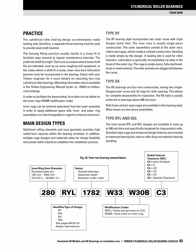
FOUR-ROW
CYLINDRICAL ROLLER BEARINGS
TIMKEN CYLINDRICAL ROLLER BEARING CATALOG 83
Inner-Ring Bore Diameter:
Standard sizes are
140 mm - 1500 mm
(5.5118 in. - 59.0551 in.)
Radial Internal
Clearance (RIC):
CF = semi-finished
C2 < 0
C3 > C0
C4 > C3
C5 > C4
C6 = Special Clearance
TYPE RY
The RY bearing style incorporates two outer races with triple
flanges (solid ribs). The inner race is usually single-piece
construction. The outer assemblies consist of the outer race,
rollers and cages, which create a unitized construction. Handling
is made simple by this design. A loading slot is used for roller
insertion. Lubrication is generally accomplished via slots in the
faces of the outer ring. The cage is single-piece, fully machined-
brass or steel material. The roller pockets are staggered between
the races.
TYPE RX
The RX bearings are four-row construction, having two single-
flanged outer races and rib rings for roller spacing. This allows
for complete disassembly for inspection. The RX style is usually
preferred in bearings above 400 mm bore.
Both brass and pin-type cages are available in this bearing style.
Most inners are two-piece assemblies.
TYPE RYL AND RXL
The most recent RYL and RXL designs are available in sizes up
to 340 mm bore and specifically designed for long-product mills.
Standard steel cage and enhanced design features are included
to maximize bearing life, reduce roller drop and optimize bearing
handling.
Fig. 22. Four-row bearing nomenclature.
PRACTICEThe cylindrical roller bearing design accommodates radial
loading only, therefore, a separate thrust bearing must be used
to provide axial shaft location.
The housing fitting practice usually results in a loose fit to
facilitate easy removal at regular maintenance intervals. The
preferred shaft fit is tight. There are occasions where loose shaft
fits are tolerated, such as on some roughing-mill equipment. In
the cases where a shaft fit is loose, inner-race bore lubrication
grooves must be incorporated in the bearing. Check with your
Timken engineer for a more details on mounting four-row
cylindrical roller bearings. Mounting information also is available
in the Timken Engineering Manual (order no. 10424) on timken.
com/catalogs.
In order to facilitate the dismounting, face slots can be added on
the inner rings (W30B modification code).
Inner rings can be ordered separately from the outer assembly
in order to equip additional spare rolls. Inner- and outer- ring
assemblies are interchangeable in regard to internal clearance.
MAIN DESIGN TYPESOptimized rolling elements and race geometry provides high
radial-load capacity within the bearing envelope. In addition,
multiple cage designs and materials allow for design flexibility
and preset radial clearance simplifies the installation process.
Identifies Type of Design:
RY
RYL
RX
RXL
See pages 84-87 for
design descriptions.
280 RYL 1782 W33 W30B C3
Modification Codes:
W33 = Holes and grooves on O.D.
W30B = Face slots on inner ring.
Series:
Outside diameter
Assembly width
Diameter under roller
Download 3D Models and 2D Drawings at cad.timken.com. •

FOUR-ROW
CYLINDRICAL ROLLER BEARINGS
84 TIMKEN CYLINDRICAL ROLLER BEARING CATALOG
ds
d Ds
D
C
B
g z x h
F
rs min
r1s min
ds
d Ds
D
C
B
g z x h
F
rs min
r1s min
ds
d Ds
D
Cg z x h
F
rs min
r1s min
B
ds
d Ds
D F
rs min
r1s min
C
B
RY-1
RY-2
RY-4
RY-6
FOUR-ROW DETAILED DESIGN TYPES
RY-1
• Two outer rings with integral ribs.
• One-piece inner ring.
• Lubrication grooves and holes
on outer rings.
• Two solid-steel or brass cages.
RY-2
• Two outer rings with integral ribs.
• Two inner rings.
• RY-2 – with lubrication grooves
and holes on outer rings.
• RY-3 – without lubrication grooves
and holes on outer rings.
• Two solid-steel or brass cages.
RY-4
• Two outer rings with integral ribs.
• Lubrication grooves and holes
on outer rings.
• Two inner rings.
• Lubrication grooves and face
slots on inner rings.
• RY-4 – extended inner ring
on one side.
• RY-5 – extended inner ring
on both sides.
• Two solid-steel or brass cages.
RY-6
• Two outer rings with integral ribs.
• One-piece inner ring.
• Face slots on outer rings.
• Two solid-steel cages.
• Download 3D Models and 2D Drawings at cad.timken.com.

FOUR-ROW
CYLINDRICAL ROLLER BEARINGS
TIMKEN CYLINDRICAL ROLLER BEARING CATALOG 85
RX-1, RX-9 and RX-11
• Two outer rings with three rib rings.
• Two inner rings.
• Four pin-type steel cages.
• RX-1 – with lubrication grooves and holes on outer rings.
• RX-9 – with oil-mist nozzles and O-rings in outer rings.
• RX-11 – with lubrication grooves, holes and O-rings
on outer rings.
RX-2
• Two outer rings with integral ribs.
• Two inner rings.
• Two solid-steel or brass cages.
• Lubrication grooves and holes on outer rings.
RX-3
• Two outer rings with three rib rings.
• Two inner rings.
• Two solid-steel or brass cages.
• Lubrication grooves and face slots on inner rings.
• Lubrication grooves and holes on outer rings.
• Extended inner ring on one side.
RX-4
• Two outer rings with three rib rings.
• Two inner rings.
• Four pin-type steel cages.
• Lubrication grooves and face slots on inner rings.
• Lubrication grooves and holes on outer rings.
• Extended inner ring on one side.
g z x h
ds
d Ds
D
C
B
F
rs min
r1s min
g z x h
ds
d Ds
D
C
B
F
rs min
r1s min
g z x h
ds
d Ds
D
C
B
F
rs min
r1s min
RX-1
RX-2
RX-4
g z x h
ds
d Ds
D
C
F
rs min
r1s min
B
RX-3
Download 3D Models and 2D Drawings at cad.timken.com. •

FOUR-ROW
CYLINDRICAL ROLLER BEARINGS
86 TIMKEN CYLINDRICAL ROLLER BEARING CATALOG
g z x h
ds
d Ds
D
C
B
F
rs min
r1s min
RX-6
g z x h
ds
d Ds
D
C
B
F
rs min
r1s min
RX-5
g z x h
ds
d Ds
D
C
B
F
rs min
r1s min
RX-7
RX-5 and RX-6
• Two outer rings with three rib rings.
• Two inner rings.
• Four pin-type steel cages.
• Lubrication grooves and face slots on inner rings.
• Lubrication grooves and holes on outer rings.
• RX-5 – identical width on outer and inner assembly.
• RX-6 – extended inner ring on one side.
RX-7
• Two outer rings with three rib rings.
• Four inner rings.
• Four pin-type steel cages.
• Lubrication grooves and holes on outer rings.
• Download 3D Models and 2D Drawings at cad.timken.com.

FOUR-ROW
CYLINDRICAL ROLLER BEARINGS
TIMKEN CYLINDRICAL ROLLER BEARING CATALOG 87
RX-8
g z x h
ds
d Ds
D
C
B
F
rs min
r1s min
RX-8
gz x h
ds
d Ds
D
C
B
F
rs min
r1s min
RX-10
z x h
d1
d Ds
D ds
C
B
F
rs min
g
r1s min
RXK-1 RXK-2
z x h
d1
d Ds
D ds
C
B
F
rs min
g
r1s min
RXK-2
RX-8 and RX-10
• Two outer rings with three rib rings.
• Two inner rings.
• Four pin-type steel cages.
• Lubrication grooves and holes on outer rings.
• Extended inner ring on one side.
• RX-10 – with oil-mist nozzles and O-rings in outer rings.
RXK-1 and RXK-2
• Two outer rings with three rib rings.
• One-piece tapered bore inner ring.
• Four pin-type steel cages.
• Lubrication grooves and holes on outer rings.
• RXK-1 – with oil-mist nozzles and O-rings in outer rings.
Download 3D Models and 2D Drawings at cad.timken.com. •

FOUR-ROW
CYLINDRICAL ROLLER BEARINGS
88 TIMKEN CYLINDRICAL ROLLER BEARING CATALOG
Bearing Dimensions Load Rating Part Number
Bored
O.D.D
WidthB
WidthC
DUR/DORF/E
StaticCo
DynamicC1
(1) Bearing(2) Type
mmin.
mmin.
mmin.
mmin.
mmin.
kNlbf.
kNlbf.
145.000 225.000 156.000 156.000 169.000 1832 1100 145RYL1452 RY-65.7087 8.8583 6.1417 6.1417 6.6535 412000 248000
160.000 230.000 130.000 130.000 180.000 1352 856 160RYL1468 RY-66.2992 9.0551 5.1181 5.1181 7.0866 30440 192400
160.000 230.000 168.000 168.000 179.000 2224 1188 160RYL1467 RY-66.2992 9.0551 6.6142 6.6142 7.0472 500000 268000
165.100 225.425 168.275 168.275 181.000 2264 1158 165RYL1451 RY-36.5000 8.8750 6.6250 6.6250 7.1260 508000 260000
180.000 260.000 168.000 168.000 202.000 2568 1452 180RYL1527 RY-67.0866 10.2362 6.6142 6.6142 7.9528 576000 326000
190.000 260.000 168.000 168.000 212.000 2604 1288 190RY1528 RY-17.4803 10.2362 6.6142 6.6142 8.3465 584000 290000
190.000 270.000 200.000 200.000 212.000 3304 1702 190RY1543 RY-17.4803 10.6299 7.8740 7.8740 8.3465 744000 382000
200.000 270.000 170.000 170.000 222.000 2788 1334 200RYL1544 RY-67.8740 10.6299 6.6929 6.6929 8.7402 628000 300000
200.000 280.000 170.000 170.000 222.000 2868 1542 200RYL1566 RY-67.8740 11.0236 6.6929 6.6929 8.7402 644000 346000
200.000 280.000 200.000 200.000 222.000 3424 1730 200RYL1567 RY-67.8740 11.0236 7.8740 7.8740 8.7402 768000 388000
200.000 290.000 192.000 192.000 226.000 3208 1774 200RYL1585 RY-67.8740 11.4173 7.5591 7.5591 8.8976 720000 398000
220.000 310.000 192.000 192.000 246.000 3432 1840 220RYL1621 RY-68.6614 12.2047 7.5591 7.5591 9.6850 772000 414000
220.000 340.000 218.000 218.000 257.180 4160 2320 220RY1683 RY-18.6614 13.3858 8.5827 8.5827 10.1252 932000 522000
230.000 330.000 206.000 206.000 260.000 3988 2120 230RYL1667 RY-69.0551 12.9921 8.1102 8.1102 10.2362 896000 478000
240.000 330.000 220.000 220.000 270.000 4320 1924 240RY1668 RY-19.4488 12.9921 8.6614 8.6614 10.6299 972000 432000
250.000 340.000 230.000 230.000 276.000 4521 1952 250RY1681 RY-19.8425 13.3858 9.0551 9.0551 10.8661 1016000 438800
260.000 370.000 220.000 220.000 292.000 5040 2580 260RYL1744 RY-610.2362 14.5669 8.6614 8.6614 11.4961 1132000 582000
260.000 380.000 280.000 280.000 294.000 6280 3240 260RY1763 RY-210.2362 14.9606 11.0236 11.0236 11.5748 1412000 728000
280.000 390.000 220.000 220.000 312.000 5200 2620 280RYL1783 RY-611.0236 15.3543 8.6614 8.6614 12.2835 1176000 590000
280.000 390.000 275.000 275.000 308.000 7020 3049 280RYL1782 RY-311.0236 15.3543 10.8268 10.8268 12.1260 1578000 685500
300.000 420.000 300.000 300.000 332.000 8720 4140 300RX1846 RX-111.8110 16.5354 11.8110 11.8110 13.0709 1960000 932000
300.000 420.000 300.000 300.000 332.000 8360 4080 300RXL1845 RX-211.8110 16.5354 11.8110 11.8110 13.0709 1880000 918000
(1)Based on 1 x 10⁶ revolutions L10 life, for the ISO life calculation method. (2)The radial internal clearance (RIC) for the bearing assembly must be included when ordering either a) the complete assembly or b) with the inner-ring set. It is advisable to order the inner-ring set independent of the outer ring set when the final grind of the inner-ring O.D. is accomplished after mounting on the roll neck.
FOUR-ROW CYLINDRICAL ROLLER BEARINGS
• Download 3D Models and 2D Drawings at cad.timken.com.

FOUR-ROW
CYLINDRICAL ROLLER BEARINGS
TIMKEN CYLINDRICAL ROLLER BEARING CATALOG 89
Sub Assembly Part NumbersMounting Data Lubrication Data
WeightChamfer Backing Diameter
Grooveg
Hole Dia.
h
Number of Holes
zInner-Ring Set(2) Outer-Ring Set rsmin r1sminShaft
ds
HousingDs
mmin.
mmin.
mmin.
mmin.
mmin.
mmin.
kglbs.
145ARVSL1452 169RYSL1452 2.0 2.0 164.2 205.0 – – – 23.000.08 0.08 6.46 8.07 50.71
160ARVSL1468 180RYSL1468 1.5 1.5 174.6 216.0 – – – 16.800.06 0.06 6.87 8.50 37.00
160ARVSL1467 179RYSL1467 2.0 2.0 174.5 211.0 – – – 23.100.08 0.08 6.87 8.31 50.80
165ARYSL1451 181RYSL1451 1.5 1.5 176.2 211.0 – – – 19.600.06 0.06 6.94 8.31 43.20
180ARVSL1527 202RYSL1527 2.1 2.1 196.3 242.0 – – – 29.700.08 0.08 7.73 9.53 65.40
190ARVS1528 212RYS1528 2.0 2.0 207.2 244.0 7.0 4.0 8 26.500.08 0.08 8.16 9.61 0.28 0.16 58.20
190ARVS1543 212RYS1543 2.1 2.1 207.2 250.0 9.6 4.5 6 37.100.08 0.08 8.16 9.84 0.38 0.18 81.79
200ARVSL1544 222RYSL1544 2.1 2.1 216.9 254.0 – – – 27.900.08 0.08 8.54 10.00 61.51
200ARVSL1566 222RYSL1566 2.1 2.1 217.5 262.0 – – – 32.400.08 0.08 8.56 10.31 71.20
200ARVSL1567 222RYSL1567 2.1 2.1 218.0 260.0 – – – 39.000.08 0.08 8.58 10.24 85.98
200ARVSL1585 226RYSL1585 2.1 2.1 220.6 270.0 – – – 41.800.08 0.08 8.69 10.63 92.10
220ARVSL1621 246RYSL1621 3.0 3.0 240.5 290.0 – – – 45.100.12 0.12 9.47 11.42 99.30
220ARVS1683 257RYS1683 3.0 3.0 251.0 309.2 10.0 5.0 8 75.600.12 0.12 9.88 12.17 0.39 0.20 166.30
230ARVSL1667 260RYSL1667 2.1 2.1 253.5 308.0 – – – 58.300.08 0.08 9.98 12.13 128.20
240ARVS1668 270RYS1668 2.1 2.1 1917.4 306.0 9.6 4.5 6 56.700.08 0.08 75.49 12.05 0.38 0.18 125.00
250ARVS1681 276RYS1681 4.0 3.5x45˚ 269.5 320.0 10.0 5.0 6 60.300.16 0.14x45˚ 10.61 12.60 0.39 0.20 132.70
260ARVSL1744 292RYSL1744 3.0 3.0 285.0 344.0 – – – 107.600.12 0.12 11.22 13.54 236.70
260ARYS1763 294RYS1763 3.0 3.0 286.5 350.0 10.0 5.0 6 107.600.12 0.12 11.28 13.78 0.39 0.20 236.70
280ARVSL1783 312RYSL1783 4.0 4.0 305.2 364.0 – – – 81.900.16 0.16 12.02 14.33 180.20
280ARYSL1782 308RYSL1782 2.5 3.5 301.8 364.0 – – – 100.700.10 0.14 11.88 14.33 221.60
300ARXS1845B 332RXS1846 3.5 7x20˚ 325.1 392.0 18.0 9.0 8 130.500.14 0.28x20˚ 12.80 15.43 0.71 0.35 287.00
300ARXSL1845 332RXSL1845 3.5 7x20˚ 326.1 392.0 12.0 6.0 8 131.900.14 0.28x20˚ 12.84 15.43 0.47 0.24 290.10
Continued on next page.
Download 3D Models and 2D Drawings at cad.timken.com. •

FOUR-ROW
CYLINDRICAL ROLLER BEARINGS
90 TIMKEN CYLINDRICAL ROLLER BEARING CATALOG
Bearing Dimensions Load Rating Part Number
Bored
O.D.D
WidthB
WidthC
DUR/DORF/E
StaticCo
DynamicC1
(1) Bearing(2) Type
mmin.
mmin.
mmin.
mmin.
mmin.
kNlbf.
kNlbf.
300.000 500.000 360.000 360.000 354.250 10160 6200 300RY2002 RY-211.8110 19.6850 14.1732 14.1732 13.9469 2288000 1392000
330.000 460.000 340.000 340.000 365.000 10840 4980 330RX1922 RX-112.9921 18.1102 13.3858 13.3858 14.3701 2440000 1120000
340.000 480.000 310.000 310.000 378.000 9640 4660 340RX1965A RX-513.3858 18.8976 12.2047 12.2047 14.8819 2164000 1048000
340.000 480.000 350.000 350.000 378.000 10880 5180 340RYL1963 RY-313.3858 18.8976 13.7795 13.7795 14.8819 2444000 1162000
370.000 520.000 380.000 380.000 409.000 14040 6500 370RX2045 RX-114.5669 20.4724 14.9606 14.9606 16.1024 3156000 1460000
380.000 540.000 300.000 300.000 421.000 10560 5420 380RX2089 RX-114.9606 21.2598 11.8110 11.8110 16.5748 2368000 1218000
380.000 540.000 400.000 380.000 422.000 14360 6840 380RX2086A RX-614.9606 21.2598 15.7480 14.9606 16.6142 3228000 1536000
380.000 540.000 400.000 400.000 422.000 14760 6900 380RX2087 RX-114.9606 21.2598 15.7480 15.7480 16.6142 3316000 1552000
390.000 540.000 320.000 320.000 431.000 11440 5540 390RX2088 RX-115.3543 21.2598 12.5984 12.5984 16.9685 2576000 1248000
390.000 550.000 400.000 400.000 432.204 13960 6680 390RY2103 RY-215.3543 21.6535 15.7480 15.7480 17.0159 3136000 1500000
400.000 560.000 410.000 410.000 445.000 16440 7460 400RX2123 RX-115.7480 22.0472 16.1417 16.1417 17.5197 3700000 1676000
431.500 571.500 300.000 300.000 465.000 10600 5200 431RX2141 RX-116.9882 22.5000 11.8110 11.8110 18.3071 2388000 1170000
440.000 620.000 450.000 450.000 487.000 20200 9100 440RX2245 RX-117.3228 24.4094 17.7165 17.7165 19.1732 4560000 2040000
460.000 685.000 400.000 400.000 518.000 15880 8780 460RX2371 RX-118.1102 26.9685 15.7480 15.7480 20.3937 3576000 1972000
480.000 650.000 450.000 450.000 525.000 21960 9540 480RX2303B RX-118.8976 25.5906 17.7165 17.7165 20.6693 4920000 2140000
500.000 670.000 485.000 450.000 540.000 22200 9520 500RX2345A RX-419.6850 26.3780 19.0945 17.7165 21.2598 5000000 2140000
500.000 710.000 480.000 480.000 558.000 23800 10780 500RX2422 RX-119.6850 27.9528 18.8976 18.8976 21.9685 5360000 2420000
500.000 720.000 530.000 530.000 568.000 28680 12440 500RX2443 RX-119.6850 28.3465 20.8661 20.8661 22.3622 6440000 2800000
510.000 680.000 500.000 500.000 560.000 26040 10280 510RX2364 RX-120.0787 26.7717 19.6850 19.6850 22.0472 5840000 2320000
510.000 730.000 520.000 520.000 569.000 27280 12680 510RX2461 RX-120.0787 28.7402 20.4724 20.4724 22.4016 6120000 2860000
530.000 760.000 520.000 520.000 587.000 27680 13080 530RX2522 RX-120.8661 29.9213 20.4724 20.4724 23.1102 6240000 2940000
550.000 740.000 510.000 510.000 600.000 28400 11780 550RX2484 RX-121.6535 29.1339 20.0787 20.0787 23.6220 6400000 2640000
(1)Based on 1 x 10⁶ revolutions L10 life, for the ISO life calculation method. (2)The radial internal clearance (RIC) for the bearing assembly must be included when ordering either a) the complete assembly or b) with the inner-ring set. It is advisable to order the inner-ring set independent of the outer ring set when the final grind of the inner-ring O.D. is accomplished after mounting on the roll neck.
FOUR-ROW CYLINDRICAL ROLLER BEARINGS – continued
• Download 3D Models and 2D Drawings at cad.timken.com.

FOUR-ROW
CYLINDRICAL ROLLER BEARINGS
TIMKEN CYLINDRICAL ROLLER BEARING CATALOG 91
Sub Assembly Part NumbersMounting Data Lubrication Data
WeightChamfer Backing Diameter
Grooveg
Hole Dia.
h
Number of Holes
zInner-Ring Set(2) Outer-Ring Set rsmin r1sminShaft
ds
HousingDs
mmin.
mmin.
mmin.
mmin.
mmin.
mmin.
kglbs.
300ARYS2002 354RYS2002 5.0 5.0 347.4 454.3 18.0 10.0 8 288.700.20 0.20 13.68 17.89 0.71 0.39 635.10
330ARXS1922 365RXS1922 2.3 10.5x20˚ 357.1 429.0 12.0 6.0 8 176.300.09 0.41x20˚ 14.06 16.89 0.47 0.24 387.80
340ARXS1965A 378RXS1965A 3.0 7x20˚ 370.1 446.0 16.0 7.5 12 179.200.12 0.28x20˚ 14.57 17.56 0.63 0.30 394.20
340ARYSL1963 378RYSL1963 3.0 8x20˚ 370.6 446.0 – – – 201.300.12 0.32X20˚ 14.59 17.56 442.90
370ARXS2045 409RXS2045 1.5 10x20˚ 401 485.0 16.0 7.5 10 257.000.06 0.39X20˚ 15.79 19.09 0.63 0.30 565.30
380ARXS2089 421RXS2089 2.0 10x20˚ 413 505.0 12.3 6.0 16 222.100.08 0.39X20˚ 16.26 19.88 0.48 0.24 488.50
380ARXS2086A 422RXS2086 4.0 7x20˚ 414 504.0 16.0 7.5 8 288.300.16 0.28x20˚ 16.30 19.84 0.63 0.30 634.20
380ARXS2087 422RXS2087 2.0 10x20˚ 412.8 502.0 16.0 8.0 8 297.800.08 0.39X20˚ 16.25 19.76 0.63 0.31 655.10
390ARXS2088 431RXS2088 2.0 10x20˚ 422.4 509.0 15.0 7.5 16 223.800.08 0.39X20˚ 16.63 20.04 0.59 0.30 492.40
390ARYS2103 432RYS2103 4.0 11x20˚ 423.1 512.2 16.0 8.0 10 304.500.16 0.43X20˚ 16.66 20.17 0.63 0.31 669.90
400ARXS2123 445RXS2123 4 12x20˚ 436 525.0 16.0 7.5 10 319.900.16 0.47x20˚ 17.17 20.67 0.63 0.30 703.70
431ARXS2141 465RXS2141 4 10.5x20˚ 456.4 545.0 18.0 9.0 8 197.100.16 0.41x20˚ 17.97 21.46 0.71 0.35 434.50
440ARXS2245 487RXS2245 4 12x20˚ 477.4 577.0 16.0 7.5 8 438.800.16 0.47x20˚ 18.80 22.72 0.63 0.30 965.30
460ARXS2371 518RXS2371 3 11x20˚ 508.4 638.0 18.0 9.0 12 530.500.12 0.43X20˚ 20.02 25.12 0.71 0.35 1167.10
480ARXS2303B 525RXS2303 5 12.7x20˚ 514.5 615.0 18.0 9.0 12 433.400.20 0.50x20˚ 20.26 24.21 0.71 0.35 953.40
500ARXS2345A 540RXS2345 5 12.5x20˚ 531 630.0 19.3 9.5 12 457.800.20 0.49x20˚ 20.91 24.80 0.76 0.37 1007.30
500ARXS2422 558RXS2422 6 18x20˚ 545.7 662.0 22.0 12.0 12 617.200.24 0.71x20˚ 21.48 26.06 0.87 0.47 1357.90
500ARXS2443 568RXS2443 5 13x20˚ 556.6 672.0 22.0 12.0 16 737.300.20 0.51x20˚ 21.91 26.46 0.87 0.47 1622.00
510ARXS2364 560RXS2364 5 14x20˚ 549.7 644.0 19.3 9.5 12 514.600.20 0.551x20˚ 21.64 25.35 0.76 0.37 1132.20
510ARXS2461 569RXS2461 6 17.50x20˚ 556.7 685.0 19.3 9.5 12 750.000.24 0.69x20o 21.92 26.97 0.76 0.37 1653.45
530ARXS2522 587RXS2522 5 12x20˚ 576 707.0 19.3 9.5 12 787.200.20 0.47x20˚ 22.68 27.83 0.76 0.37 1731.80
550ARXS2484 600RXS2484 2 15x20˚ 588.5 698.0 22.0 12.0 16 631.700.08 0.59x20˚ 23.17 27.48 0.87 0.47 1389.70
Continued on next page.
Download 3D Models and 2D Drawings at cad.timken.com. •

FOUR-ROW
CYLINDRICAL ROLLER BEARINGS
92 TIMKEN CYLINDRICAL ROLLER BEARING CATALOG
Bearing Dimensions Load Rating Part Number
Bored
O.D.D
WidthB
WidthC
DUR/DORF/E
StaticCo
DynamicC1
(1) Bearing(2) Type
mmin.
mmin.
mmin.
mmin.
mmin.
kNlbf.
kNlbf.
560.000 820.000 600.000 600.000 625.000 34240 16180 560RX2644 RX-122.0472 32.2835 23.6220 23.6220 24.6063 7720000 3640000
571.100 812.970 594.000 594.000 636.000 35000 15440 571RX2622 RX-122.4843 32.0067 23.3858 23.3858 25.0394 7880000 3480000
600.000 820.000 575.000 575.000 660.000 36120 14780 600RX2643A RX-123.6220 32.2835 22.6378 22.6378 25.9843 8120000 3320000
600.000 820.000 575.000 575.000 660.000 36120 14780 600RX2643B RX-923.6220 32.2835 22.6378 22.6378 25.9843 8120000 3320000
600.000 870.000 640.000 640.000 672.000 40000 18040 600RX2744 RX-123.6220 34.2520 25.1969 25.1969 26.4567 9000000 4060000
650.000 900.000 650.000 650.000 704.000 41200 18980 650RX2803A RX-125.5906 35.4331 25.5906 25.5906 27.7165 9280000 4260000
650.000 920.000 670.000 670.000 723.000 45600 19520 650RX2841C RX-125.5906 36.2205 26.3780 26.3780 28.4646 10240000 4380000
690.000 980.000 715.000 715.000 767.500 53200 22400 690RX2965 RX-127.1654 38.5827 28.1496 28.1496 30.2165 11960000 5040000
690.000 980.000 750.000 750.000 766.000 54800 23000 690RX2966 RX-927.1654 38.5827 29.5276 29.5276 30.1575 12320000 5160000
700.000 930.000 620.000 620.000 763.000 44400 16920 700RX2862 RX-127.5591 36.6142 24.4094 24.4094 30.0394 10000000 380000
700.000 980.000 700.000 700.000 774.000 51200 21000 700RX2964A RX-127.5591 38.5827 27.5591 27.5591 30.4724 11520000 4720000
705.000 1066.905 635.000 635.000 796.000 45200 22600 705RX3131B RX-127.7559 42.0041 25.0000 25.0000 31.3386 10120000 5100000
710.000 1000.000 715.000 715.000 787.500 54400 22800 710RX3006 RX-127.9528 39.3701 28.1496 28.1496 31.0039 12240000 5120000
730.000 960.000 620.000 620.000 790.000 45200 17500 730RX2922 RX-128.7402 37.7953 24.4094 24.4094 31.1024 10120000 3940000
730.000 1030.000 750.000 750.000 809.000 59200 24600 730RX3064 RX-128.7402 40.5512 29.5276 29.5276 31.8504 13280000 5520000
730.000 1030.000 750.000 750.000 809.000 59200 24600 730RX3064A RX-1128.7402 40.5512 29.5276 29.5276 31.8504 13280000 5520000
750.000 1000.000 670.000 670.000 813.000 52000 20400 750RX3005 RX-129.5276 39.3701 26.3780 26.3780 32.0079 11680000 4580000
760.000 1080.000 790.000 790.000 846.000 63600 26800 760RX3166 RX-129.9213 42.5197 31.1024 31.1024 33.3071 14320000 6040000
760.925 1079.600 787.400 787.400 846.000 64000 26800 761RX3166B RX-129.9577 42.5039 31.0000 31.0000 33.3071 14440000 6040000
761.425 1079.600 787.400 787.400 846.000 64000 26800 761RX3166 RX-129.9774 42.5039 31.0000 31.0000 33.3071 14440000 6040000
770.000 1075.000 770.000 770.000 847.000 62800 26000 770RX3151 RX-130.3150 42.3228 30.3150 30.3150 33.3465 14160000 5860000
780.000 1070.000 780.000 780.000 853.000 62400 25400 780RX3141 RX-130.7087 42.1260 30.7087 30.7087 33.5827 14040000 5720000
(1)Based on 1 x 10⁶ revolutions L10 life, for the ISO life calculation method. (2)The radial internal clearance (RIC) for the bearing assembly must be included when ordering either a) the complete assembly or b) with the inner-ring set. It is advisable to order the inner-ring set independent of the outer ring set when the final grind of the inner-ring O.D. is accomplished after mounting on the roll neck.
FOUR-ROW CYLINDRICAL ROLLER BEARINGS – continued
• Download 3D Models and 2D Drawings at cad.timken.com.

FOUR-ROW
CYLINDRICAL ROLLER BEARINGS
TIMKEN CYLINDRICAL ROLLER BEARING CATALOG 93
Sub Assembly Part NumbersMounting Data Lubrication Data
WeightChamfer Backing Diameter
Grooveg
Hole Dia.
h
Number of Holes
zInner-Ring Set(2) Outer-Ring Set rsmin r1sminShaft
ds
HousingDs
mmin.
mmin.
mmin.
mmin.
mmin.
mmin.
kglbs.
560ARXS2644 625RXS2644 6 20x20˚ 611.4 761.0 25.3 13.0 16 1095.400.24 0.79x20˚ 24.07 29.96 1.00 0.51 2409.90
571ARXS2622 636RXS2622 5 14x20˚ 623.3 758.0 25.3 13.0 16 1009.300.20 0.55x20˚ 24.54 29.84 1.00 0.51 2220.40
600ARXS2643 660RXS2643A 3 15x20˚ 648.3 770.0 22.0 12.0 16 925.000.12 0.59x20˚ 25.52 30.31 0.87 0.47 2035.00
600ARXS2643 660RXS2643B 3 15x20˚ 648.3 770.0 32.0 2x1.70 8 923.700.12 0.59x20˚ 25.52 30.31 1.26 2x0.067 2032.20
600ARXS2744 672RXS2744 7.5 20x20˚ 658.3 808.0 19.3 9.5 16 1312.000.30 0.79x20˚ 25.92 31.81 0.76 0.37 2891.90
650ARXS2803 704RXS2803 7.5 20x20˚ 686.9 850.0 22.0 12.0 16 1244.900.30 0.79x20˚ 27.04 33.46 0.87 0.47 2738.70
650ARXS2841 723RXS2841 4 18x20˚ 705.9 859.0 25.3 13.0 16 1458.300.16 0.71x20˚ 27.79 33.82 1.00 0.51 3208.20
690ARXS2965 768RXS2965 4 20x20˚ 750.4 911.5 25.3 13.0 16 1781.400.16 0.79x20˚ 29.54 35.89 1.00 0.51 3919.00
690ARXS2966 766RXS2966 7.5 20x20˚ 749.6 910.0 46.0 2x1.70 12 1854.100.30 0.79x20˚ 29.51 35.83 1.81 2x0.067 4079.10
700ARXS2862 763RXS2862 3 18x20˚ 745.9 875.0 22.0 12.0 16 1188.700.12 0.71x20˚ 29.37 34.45 0.87 0.47 2615.20
700ARXS2964A 774RXS2964 6 13x15˚ 758.7 910.0 25.3 13.0 16 1690.000.24 0.51x15˚ 29.87 35.83 1.00 0.51 3725.77
705ARXS3131B 796RXS3131 6 6 784.5 986.0 34.0 19.0 16 2081.900.24 0.24 30.89 38.82 1.34 0.75 4580.10
710ARXS3006 788RXS3006 4 17x20˚ 773.5 931.5 25.3 13.0 16 1840.600.16 0.67x20˚ 30.45 36.67 1.00 0.51 4049.40
730ARXS2922 790RXS2922 3 20x20˚ 776.3 908.0 22.0 12.0 16 1230.500.12 0.79x20˚ 30.56 35.75 0.87 0.47 2707.20
730ARXS3064 809RXS3064 6 21x20˚ 793.9 959.0 25.3 13.0 16 2050.100.24 0.83x20˚ 31.26 37.76 1.00 0.51 4510.20
730ARXS3064 809RXS3064A 6 21x20˚ 793.9 959.0 25.3 13.0 16 2043.700.24 0.83x20˚ 31.26 37.76 1.00 0.51 4496.00
750ARXS3005 813RXS3005 3 20x20˚ 795.9 943.0 22.0 12.0 16 1508.700.12 0.79x20˚ 31.33 37.13 0.87 0.47 3319.10
760ARXS3166 846RXS3166B 8 19x20˚ 830.5 1006.0 22.0 12.0 8 2423.000.31 0.75x20˚ 32.70 39.61 0.87 0.47 5330.70
761ARXS3166B 846RXS3166A 8 19x20˚ 830.5 1006.0 22.0 12.0 8 2406.300.31 0.75x20˚ 32.70 39.61 0.87 0.47 5293.90
761ARXS3166 846RXS3166 8 19x20˚ 830.5 1006.0 22.0 12.0 8 2402.600.31 0.75x20˚ 32.70 39.61 0.87 0.47 5285.80
770ARXS3151 847RXS3151 7.5 18x20˚ 831.7 1003.0 25.3 13.0 16 1655.000.30 0.71x20˚ 32.74 39.49 1.00 0.51 3648.61
780ARXS3141 853RXS3141 6 25x20˚ 835.9 1005.0 25.3 13.0 16 2142.000.24 0.98x20˚ 32.91 39.57 1.00 0.51 4712.30
Continued on next page.
Download 3D Models and 2D Drawings at cad.timken.com. •

FOUR-ROW
CYLINDRICAL ROLLER BEARINGS
94 TIMKEN CYLINDRICAL ROLLER BEARING CATALOG
Bearing Dimensions Load Rating Part Number
Bored
O.D.D
WidthB
WidthC
DUR/DORF/E
StaticCo
DynamicC1
(1) Bearing(2) Type
mmin.
mmin.
mmin.
mmin.
mmin.
kNlbf.
kNlbf.
800.000 1080.000 700.000 700.000 878.000 59200 22600 800RX3165 RX-131.4961 42.5197 27.5591 27.5591 34.5669 13280000 5100000
800.000 1080.000 750.000 750.000 880.000 58800 22600 800RX3164 RX-131.4961 42.5197 29.5276 29.5276 34.6457 13240000 5080000
820.000 1130.000 650.000 650.000 891.000 52400 23200 820RX3263 RX-132.2835 44.4882 25.5906 25.5906 35.0787 11800000 5220000
820.000 1100.000 745.000 720.000 892.000 57600 23000 820RX3201A RX-1032.2835 43.3071 29.3307 28.3465 35.1181 12960000 5180000
820.000 1130.000 800.000 800.000 903.000 68400 27400 820RX3264 RX-132.2835 44.4882 31.4961 31.4961 35.5512 15360000 6160000
820.000 1130.000 800.000 800.000 903.000 68400 27400 820RX3264A RX-932.2835 44.4882 31.4961 31.4961 35.5512 15360000 6160000
820.000 1130.000 825.000 800.000 903.000 68400 27400 820RX3264C RX-832.2835 44.4882 32.4803 31.4961 35.5512 15360000 6160000
820.000 1130.000 825.000 800.000 903.000 68400 27400 820RX3264D RX-1032.2835 44.4882 32.4803 31.4961 35.5512 15360000 6160000
850.000 1150.000 840.000 840.000 928.000 74800 28800 850RX3304 RX-133.4646 45.2756 33.0709 33.0709 36.5354 16800000 6480000
850.000 1180.000 850.000 850.000 940.000 72800 29600 850RX3365 RX-133.4646 46.4567 33.4646 33.4646 37.0079 16400000 6660000
862.980 1219.302 876.300 889.000 956.000 84000 34600 863RX3445A RX-133.9756 48.0040 34.5000 35.0000 37.6378 18840000 7780000
880.000 1180.000 750.000 750.000 945.000 68000 27400 880RXK3364A RXK-134.6457 46.4567 29.5276 29.5276 37.2047 15240000 6140000
880.000 1180.000 750.000 750.000 945.300 66400 26600 880RXK3366 RXK-234.6457 46.4567 29.5276 29.5276 37.2165 14920000 6000000
900.000 1220.000 840.000 840.000 989.000 78800 30200 900RX3444 RX-135.4331 48.0315 33.0709 33.0709 38.9370 17680000 6780000
950.000 1360.000 1000.000 1000.000 1075.000 108800 43200 950RX3723 RX-137.4016 53.5433 39.3701 39.3701 42.3228 24480000 9700000
1040.000 1439.890 1000.000 1000.000 1133.000 101200 42600 1040RX3882 RX-740.9449 56.6886 39.3701 39.3701 44.6063 22760000 9580000
(1)Based on 1 x 10⁶ revolutions L10 life, for the ISO life calculation method. (2)The radial internal clearance (RIC) for the bearing assembly must be included when ordering either a) the complete assembly or b) with the inner-ring set. It is advisable to order the inner-ring set independent of the outer ring set when the final grind of the inner-ring O.D. is accomplished after mounting on the roll neck.
FOUR-ROW CYLINDRICAL ROLLER BEARINGS – continued
• Download 3D Models and 2D Drawings at cad.timken.com.

FOUR-ROW
CYLINDRICAL ROLLER BEARINGS
TIMKEN CYLINDRICAL ROLLER BEARING CATALOG 95
Sub Assembly Part NumbersMounting Data Lubrication Data
WeightChamfer Backing Diameter
Grooveg
Hole Dia.
h
Number of Holes
zInner-Ring Set(2) Outer-Ring Set rsmin r1sminShaft
ds
HousingDs
mmin.
mmin.
mmin.
mmin.
mmin.
mmin.
kglbs.
800ARXS3165 878RXS3165 3 20x20˚ 864.3 1014.0 26.0 15.0 16 1915.600.12 0.79x20˚ 34.03 39.92 1.02 0.59 4214.40
800ARXS3164 880RXS3164 – 18x20˚ 863.7 1016.0 25.3 13.0 16 2050.00– 0.71x20˚ 34.00 40.00 1.00 0.51 4519.43
820ARXS3263 891RXS3263 6 20x20˚ 873.8 1061.0 25.3 13.0 16 2030.000.24 0.79x20˚ 34.40 41.77 1.00 0.51 4475.34
820ARXS3201A 892RXS3201A 3 22x20˚ 872.2 1036.0 42.0 2x1.70 12 1969.800.12 0.87x20˚ 34.34 40.79 1.65 2x0.067 4333.60
820ARXS3264 903RXS3264 7.5 23x20˚ 882.5 1059.0 36.0 20.0 16 2490.400.30 0.91x20˚ 34.74 41.69 1.42 0.79 5478.80
820ARXS3264 903RXS3264A 7.5 23x20˚ 882.5 1059.0 46.0 2x1.70 12 2495.000.30 0.91x20˚ 34.74 41.69 1.81 2x0.067 5497.50
820ARXS3264C 903RXS3264 7.5 23x20˚ 882.5 1059.0 36.0 20.0 16 2512.300.30 0.91x20˚ 34.74 41.69 1.42 0.79 5527.10
820ARXS3264C 903RXS3264A 7.5 23x20˚ 882.5 1059.0 46.0 2x1.70 12 2495.000.30 0.91x20˚ 34.74 41.69 1.81 2x0.067 5545.40
850ARXS3304 928RXS3304 4 23x20˚ 910.8 1080.0 22.0 12.0 16 2605.200.16 0.91x20˚ 35.86 42.52 0.87 0.47 5731.50
850ARXS3365 940RXS3365 7.5 25x11˚20´ 911.7 1106.0 36.0 20.0 16 2870.000.30 0.98x11˚20´ 35.89 43.54 1.42 0.79 6408.00
863ARXS3445A 956RXS3445A 5 12x20˚ 938.2 1140.0 25.3 13.0 16 3431.300.20 0.47x20˚ 36.94 44.88 1.00 0.51 7548.90
880ARVKS3364 945RXS3364A 7.5 8 930 1105.0 46.0 2x1.70 8 2510.700.30 0.31 36.61 43.50 1.81 2x0.067 5523.60
880ARVKS3366 945RXS3366 7.5 8 930 1105.0 27.0 15.0 20 2497.400.30 0.31 36.61 43.50 1.06 0.59 5494.20
900ARXS3444 989RXS3444 4 24x24˚ 971.8 1149.0 22.0 12.0 16 2959.200.16 0.95x20˚ 38.26 45.24 0.87 0.47 6510.30
950ARXS3723 1075RXS3723 5 22x24˚ 1057.1 1275.0 34.0 19.0 16 4987.000.20 0.87x20˚ 41.62 50.20 1.34 0.75 10971.50
1040ARXS3882 1133RXS3882 7.5 27x20˚ 1110.2 1353.0 22.0 12.0 16 4975.500.30 1.06x20˚ 43.71 53.27 0.87 0.47 10969.80
Download 3D Models and 2D Drawings at cad.timken.com. •

Shaft Diameter
DimensionsBearing
Designation
Used With Inner Ring
Designation
Load Rating Speed Ratings
StaticCo
Basic Dynamic
C(1)Fw D C/B rs min Oil Grease
in.mmin.
mmin.
mmin.
mmin.
kNlbf.
kNlbf.
RPM
3.75 95.25 120.65 50.8 2.54 HJ-607632 IR-506032 398 193 3700 33003.75 4.75 2 0.1 IR-526032 89400 43300
4 101.6 127 50.8 2.54 HJ-648032 IR-526432 428 201 3500 31004 5 2 0.1 IR-546432 96200 45100
IR-566432IR-566432
4.25 107.95 133.35 50.8 2.54 HJ-688432 IR-566832 444 203 3300 29004.25 5.25 2 0.1 IR-606832 99900 45700
4.5 114.3 152.4 57.15 2.54 HJ-729636 IR-607236 517 285 3200 28004.5 6 2.25 0.1 116000 64000
114.3 152.4 63.5 2.54 HJ-729640 IR-607240 599 320 3200 28004.5 6 2.5 0.1 135000 71900
5 127 165.1 50.8 2.54 HJ-8010432 – 517 278 2800 24005 6.5 2 0.1 116000 62400
127 165.1 57.15 2.54 HJ-8010436 IR-648036 590 308 2800 25005 6.5 2.25 0.1 IR-688036 133000 69200
127 165.1 63.5 2.54 HJ-8010440 IR-648040 684 345 2800 25005 6.5 2.5 0.1 154000 77600
5.5 139.7 177.8 63.5 2.54 HJ-8811240 IR-728840 697 342 2600 23005.5 7 2.5 0.1 157000 76900
139.7 177.8 76.2 2.54 HJ-8811248 IR-728848 883 411 2500 22005.5 7 3 0.1 198000 92400
5.75 146.05 184.15 76.2 3.05 HJ-9211648 IR-769248 918 419 2400 21005.75 7.25 3 0.12 206000 94200
6 152.4 190.5 63.5 3.05 HJ-9612040 IR-809640 777 364 2300 20006 7.5 2.5 0.12 175000 81800
152.4 190.5 76.2 3.05 HJ-9612048 IR-809648 984 438 2200 20006 7.5 3 0.12 221000 98400
HJ SERIES
CYLINDRICAL ROLLER BEARINGS
96 TIMKEN CYLINDRICAL ROLLER BEARING CATALOG
FW
D
C
D
B
HJ HJ with IR
HJ SERIES
• Clearance fit suggested for outer ring when housing is
stationary relative to load.
• Tight transition fit suggested if housing rotates relative
to load.
• Consult your Timken representative for oscillating
applications (e.g., low radial-clearance concerns).
• Unmarked end of outer ring should be assembled
against housing shoulder to clear maximum allowed
housing fillet ra max (equal to rs min).
• Meets Military Standard MS 51961.
(1)Cg factor for bearing without inner ring.
• Download 3D Models and 2D Drawings at cad.timken.com.

HJ SERIES
CYLINDRICAL ROLLER BEARINGS
TIMKEN CYLINDRICAL ROLLER BEARING CATALOG 97
WeightGeometry
Factor Cg
(1)
Mounting Dimensions Clearance Fit Bearing
Designation
Mounting Dimensions Tight Transition Fit Shoulder
Diameter ±0.38 ±0.015
Da
S H
Max. Min. Max. Min. Max. Min. Max. Min.
kg lbs.
mmin.
mmin.
mmin.
mmin.
mmin.
mmin.
mmin.
mmin.
mmin.
mmin.
1.455 0.1011 95.25 95.227 120.691 120.65 HJ-607632 95.217 95.192 120.594 120.635 111.133.208 3.75 3.7491 4.7516 4.75 3.7487 3.7477 4.7478 4.7494 4.375
1.541 0.106 101.6 101.577 127.041 127 HJ-648032 101.564 101.542 126.944 126.985 117.483.397 4 3.9991 5.0016 5 3.9986 3.9977 4.9978 4.9994 4.625
1.626 0.1099 107.95 107.927 133.391 133.35 HJ-688432 107.914 107.892 133.294 133.335 123.833.586 4.25 4.2491 5.2516 5.25 4.2486 4.2477 5.2478 5.2494 4.875
3.035 0.1100 114.3 114.277 152.441 152.4 HJ-729636 114.264 114.242 152.344 152.385 138.116.691 4.5 4.4991 6.0016 6 4.4986 4.4977 5.9978 5.9994 5.438
3.372 0.1137 114.3 114.277 152.441 152.4 HJ-729640 114.264 114.242 152.344 152.385 138.117.434 4.5 4.4991 6.0016 6 4.4986 4.4977 5.9978 5.9994 5.438
2.66 0.1162 127 126.975 165.141 165.1 HJ-8010432 126.959 126.934 165.044 165.085 150.815.86 5 4.999 6.5016 6.5 4.9984 4.9974 6.4978 6.4994 5.938
3.324 0.1188 127 126.975 165.141 165.1 HJ-8010436 126.959 126.934 165.044 165.085 150.817.327 5 4.999 6.5016 6.5 4.9984 4.9974 6.4978 6.4994 5.938
3.693 0.1213 127 126.975 165.141 165.1 HJ-8010440 126.959 126.934 165.044 165.085 150.818.141 5 4.999 6.5016 6.5 4.9984 4.9974 6.4978 6.4994 5.938
4.014 0.1297 139.7 139.675 177.841 177.8 HJ-8811240 139.659 139.634 177.744 177.785 163.518.849 5.5 5.499 7.0016 7 5.4984 5.4974 6.9978 6.9994 6.438
4.817 0.1369 139.7 139.675 177.841 177.8 HJ-8811248 139.659 139.634 177.744 177.785 163.5110.62 5.5 5.499 7.0016 7 5.4984 5.4974 6.9978 6.9994 6.438
5.009 0.1409 146.05 146.025 184.196 184.15 HJ-9211648 146.009 145.984 184.089 184.135 169.8611.04 5.75 5.749 7.2518 7.25 5.7484 5.7474 7.2476 7.2494 6.688
4.335 0.1384 152.4 152.375 190.546 190.5 HJ-9612040 152.359 152.334 190.439 190.485 176.219.557 6 5.999 7.5018 7.5 5.9984 5.9974 7.4976 7.4994 6.938
5.202 0.1461 152.4 152.375 190.546 190.5 HJ-9612048 152.359 152.334 190.439 190.485 176.2111.47 6 5.999 7.5018 7.5 5.9984 5.9974 7.4976 7.4994 6.938
Continued on next page.
shaft surface to be58 HRC or equivalent
ra
SDa H
Download 3D Models and 2D Drawings at cad.timken.com. •
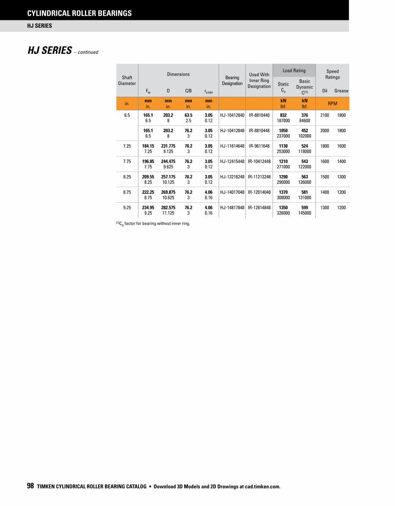
Shaft Diameter
DimensionsBearing
Designation
Used With Inner Ring
Designation
Load Rating Speed Ratings
StaticCo
Basic Dynamic
C(1)Fw D C/B rs min Oil Grease
in.mmin.
mmin.
mmin.
mmin.
kNlbf.
kNlbf.
RPM
6.5 165.1 203.2 63.5 3.05 HJ-10412840 IR-8810440 832 376 2100 18006.5 8 2.5 0.12 187000 84600
165.1 203.2 76.2 3.05 HJ-10412848 IR-8810448 1050 452 2000 18006.5 8 3 0.12 237000 102000
7.25 184.15 231.775 76.2 3.05 HJ-11614648 IR-9611648 1130 524 1800 16007.25 9.125 3 0.12 253000 118000
7.75 196.85 244.475 76.2 3.05 HJ-12415448 IR-10412448 1210 543 1600 14007.75 9.625 3 0.12 271000 122000
8.25 209.55 257.175 76.2 3.05 HJ-13216248 IR-11213248 1290 563 1500 13008.25 10.125 3 0.12 290000 126000
8.75 222.25 269.875 76.2 4.06 HJ-14017048 IR-12014048 1370 581 1400 12008.75 10.625 3 0.16 308000 131000
9.25 234.95 282.575 76.2 4.06 HJ-14817848 IR-12814848 1350 599 1300 12009.25 11.125 3 0.16 326000 145000
HJ SERIES
CYLINDRICAL ROLLER BEARINGS
98 TIMKEN CYLINDRICAL ROLLER BEARING CATALOG
HJ SERIES – continued
(1)Cg factor for bearing without inner ring.
• Download 3D Models and 2D Drawings at cad.timken.com.

HJ SERIES
CYLINDRICAL ROLLER BEARINGS
TIMKEN CYLINDRICAL ROLLER BEARING CATALOG 99
WeightGeometry
Factor Cg
(1)
Mounting Dimensions Clearance Fit Bearing
Designation
Mounting Dimensions Tight Transition Fit Shoulder
Diameter ±0.38 ±0.015
Da
S H
Max. Min. Max. Min. Max. Min. Max. Min.
kg lbs.
mmin.
mmin.
mmin.
mmin.
mmin.
mmin.
mmin.
mmin.
mmin.
mmin.
4.656 0.1459 165.1 165.075 203.246 203.2 HJ-10412840 165.059 165.034 203.139 203.185 188.9110.26 6.5 6.499 8.0018 8 6.4984 6.4974 7.9976 7.9994 7.438
5.582 0.1539 165.1 165.075 203.246 203.2 HJ-10412848 165.059 165.034 203.139 203.185 188.9112.31 6.5 6.499 8.0018 8 6.4984 6.4974 7.9976 7.9994 7.438
7.888 0.1586 184.15 184.12 231.821 231.775 HJ-11614648 184.099 184.069 231.714 231.76 216.017.39 7.25 7.2488 9.1268 9.125 7.248 7.2468 9.1226 9.1244 8.5
8.37 0.1662 196.85 196.82 244.521 244.475 HJ-12415448 196.799 196.769 244.414 244.46 228.618.45 7.75 7.7488 9.6268 9.625 7.748 7.7468 9.6226 9.6244 9
8.852 0.1736 209.55 209.52 257.226 257.175 HJ-13216248 209.499 209.469 257.109 257.16 241.319.51 8.25 8.2488 10.127 10.125 8.248 8.2468 10.122 10.124 9.5
9.333 0.181 222.25 222.22 269.926 269.875 HJ-14017048 222.199 222.169 269.809 269.86 25420.58 8.75 8.7488 10.627 10.625 8.748 8.7468 10.622 10.624 10
9.815 0.1885 234.95 234.92 282.626 282.575 HJ-14817848 234.899 234.869 282.509 282.56 266.721.64 9.25 9.2488 11.127 11.125 9.248 9.2468 11.122 11.124 10.5
Download 3D Models and 2D Drawings at cad.timken.com. •

INNER RINGS (IR)
CYLINDRICAL ROLLER BEARINGS
100 TIMKEN CYLINDRICAL ROLLER BEARING CATALOG
Shaft Diameter
Dimensions Inner-Ring Designation
Weight
Loose Transition FitS
Interference Fit Used with Bearing Designation
d F B rs min Max. Min. Max. Min.
in.mmin.
mmin.
mmin.
mmin.
kg lbs.
mmin.
mmin.
mmin.
mmin.
3.125 79.375 95.25 50.8 2.54 IR-506032 0.88 79.365 79.347 79.398 79.385 HJ-6076323.125 3.75 2 0.1 1.94 3.1246 3.1239 3.1259 3.1254
3.25 82.55 95.25 50.8 2.54 IR-526032 0.708 82.537 82.517 82.578 82.563 HJ-6076323.25 3.75 2 0.1 1.56 3.2495 3.2487 3.2511 3.2505
82.55 101.6 50.8 2.54 IR-526432 1.089 82.537 82.517 82.578 82.563 HJ-6480323.25 4 2 0.1 2.4 3.2495 3.2487 3.2511 3.2505
3.375 85.725 101.6 50.8 2.54 IR-546432 0.93 85.712 85.692 85.753 85.738 HJ-6480323.375 4 2 0.1 2.05 3.3745 3.3737 3.3761 3.3755
3.5 88.9 101.6 50.8 2.54 IR-566432 0.757 88.887 88.867 88.928 88.913 HJ-6480323.5 4 2 0.1 1.67 3.4995 3.4987 3.5011 3.5005
88.9 107.95 50.8 2.54 IR-566832 1.179 88.887 88.867 88.928 88.913 HJ-6884323.5 4.25 2 0.1 2.6 3.4995 3.4987 3.5011 3.5005
3.75 95.25 107.95 50.8 2.54 IR-606832 1.012 95.237 95.217 95.278 95.263 HJ-6884323.75 4.25 2 0.1 2.23 3.7495 3.7487 3.7511 3.7505
95.25 114.3 57.15 2.54 IR-607236 1.406 95.237 95.217 95.278 95.263 HJ-7296363.75 4.5 2.25 0.1 3.1 3.7495 3.7487 3.7511 3.7505
95.25 114.3 63.5 2.54 IR-607240 1.565 95.237 95.217 95.278 95.263 HJ-7296403.75 4.5 2.5 0.1 3.45 3.7495 3.7487 3.7511 3.7505
4 101.6 127 57.15 2.54 IR-648036 2.046 101.587 101.567 101.628 101.613 HJ-80104364 5 2.25 0.1 4.51 3.9995 3.9987 4.0011 4.0005
101.6 127 63.5 2.54 IR-648040 2.272 101.587 101.567 101.628 101.613 HJ-80104404 5 2.5 0.1 5.01 3.9995 3.9987 4.0011 4.0005
4.25 107.95 127 57.15 2.54 IR-688036 1.565 107.937 107.917 107.978 107.963 HJ-80104364.25 5 2.25 0.1 3.45 4.2495 4.2487 4.2511 4.2505
4.5 114.3 139.7 63.5 2.54 IR-728840 2.495 114.287 114.267 114.328 114.313 HJ-88112404.5 5.5 2.5 0.1 5.5 4.4995 4.4987 4.5011 4.5005
114.3 139.7 76.2 2.54 IR-728848 2.989 114.287 114.267 114.328 114.313 HJ-88112484.5 5.5 3 0.1 6.59 4.4995 4.4987 4.5011 4.5005
4.75 120.65 146.05 76.2 3.05 IR-769248 3.18 120.635 120.612 120.683 120.665 HJ-92116484.75 5.75 3 0.12 7.01 4.7494 4.7485 4.7513 4.7506
INNER RINGS (IR)
Continued on next page.
• Ideal choice where the shaft is not practical to use as inner
raceway.
• Designed to meet established inch tolerances.
• Maximum shaft fillet radius cannot exceed inner-ring bore
chamfer as shown.
• Optional centralized lubrication groove (bore) or through-
hole available – specify when ordering.
• Designed to be axially clamped against shoulder for loose
transition fit on shaft.
• After mounting, for tight transition fit (keeping inner ring
from rotating relative to shaft), inner-ring O.D. must not
exceed raceway diameter on matching bearing.
• After mounting, if O.D. of inner ring exceeds the required
raceway diameter for matching bearing, ring should be
ground to proper diameter while mounted on shaft.
• Unmarked end of inner ring to be assembled against the
shaft shoulder to ensure clearing the maximum allowable
shaft fillet as indicated in tables shown.
• Download 3D Models and 2D Drawings at cad.timken.com.

INNER RINGS (IR)
CYLINDRICAL ROLLER BEARINGS
TIMKEN CYLINDRICAL ROLLER BEARING CATALOG 101
Shaft Diameter
Dimensions Inner-Ring Designation
Weight
Loose Transition FitS
Interference Fit Used with Bearing Designation
d F B rs min Max. Min. Max. Min.
in.mmin.
mmin.
mmin.
mmin.
kg lbs.
mmin.
mmin.
mmin.
mmin.
5 127 152.4 63.5 3.05 IR-809640 2.781 126.985 126.962 127.033 127.015 HJ-96120405 6 2.5 0.12 6.13 4.9994 4.9985 5.0013 5.0006
127 152.4 76.2 3.05 IR-809648 3.325 126.985 126.962 127.033 127.015 HJ-96120485 6 3 0.12 7.33 4.9994 4.9985 5.0013 5.0006
5.5 139.7 165.1 63.5 3.05 IR-8810440 3.035 139.685 139.662 139.733 139.715 HJ-104128405.5 6.5 2.5 0.12 6.69 5.4994 5.4985 5.5013 5.5006
139.7 165.1 76.2 3.05 IR-8810448 3.629 139.685 139.662 139.733 139.715 HJ-104128485.5 6.5 3 0.12 8 5.4994 5.4985 5.5013 5.5006
6 152.4 184.15 76.2 3.05 IR-9611648 4.935 152.385 152.362 152.433 152.415 HJ-116146486 7.25 3 0.12 10.88 5.9994 5.9985 6.0013 6.0006
6.5 165.1 196.85 76.2 3.05 IR-10412448 5.343 165.085 165.062 165.133 165.115 HJ-124154486.5 7.75 3 0.12 11.78 6.4994 6.4985 6.5013 6.5006
7 177.8 209.55 76.2 3.05 IR-11213248 5.389 177.785 177.762 177.833 177.815 HJ-132162487 8.25 3 0.12 11.88 6.9994 6.9985 7.0013 7.0006
7.5 190.5 222.25 76.2 4.06 IR-12014048 6.11 190.485 190.454 190.536 190.515 HJ-140170487.5 8.75 3 0.16 13.47 7.4994 7.4982 7.5014 7.5006
8 203.2 234.95 76.2 4.06 IR-12814848 6.518 203.185 203.154 203.236 203.215 HJ-148178488 9.25 3 0.16 14.37 7.9994 7.9982 8.0014 8.0006
r
d F
B
ra
S
Inner Ring Inner Ring
Download 3D Models and 2D Drawings at cad.timken.com. •

(1)Inner ring can be ordered separately.
5200, A5200 METRIC SERIES
CYLINDRICAL ROLLER BEARINGS
102 TIMKEN CYLINDRICAL ROLLER BEARING CATALOG
5200, A5200 METRIC SERIES
• Ring tolerances are found on page 39.
• Life and load calculations are found in the
engineering section of this catalog.
• Shaft and housing fits, tolerances and shaft
diameters are found on page 38. ds
d Ds
D
B
30˚
F
rs min
r1s min
WS WM
ds
d Ds
D
B
30˚
F
rs min
r1s min
Outer ring and roller assembly Inner rings(1) Complete bearing
52xx-WS A-52xx A-52xx-WS
IN THE BEARING NUMBER
W = double-ribbed outer ring.
S = stamped-steel, land-riding cage.
M = machined-brass, land-riding cage.
+ =
+ =
• Download 3D Models and 2D Drawings at cad.timken.com.

5200, A5200 METRIC SERIES
CYLINDRICAL ROLLER BEARINGS
TIMKEN CYLINDRICAL ROLLER BEARING CATALOG 103
Bearing Dimensions Load Rating Part Number
Mounting Data
s(3)
Geo-metry Factor
Cg
Thermal Speed Ratings Weight
ChamferBacking Diameter
Bored
O.D.D
WidthB
DUR/DORF/E
StaticC0
DynamicC1
(1) Bearing(2) Type rsmin r1sminShaft
ds
HousingDs
Oil Grease
mmin.
mmin.
mmin.
mmin.
kNlbf.
kNlbf.
mmin.
mmin.
mmin.
mmin.
mmin.
RPM RPMkglbs.
100.000 180.000 60.325 121.133 594 474 A-5220-WS WS 4.4 2.1 117.1 165.6 4.26 0.131 2800 2500 6.303.9370 7.0866 2.3750 4.7690 134000 107000 0.16 0.08 4.61 6.52 0.168 14.00
110.000 200.000 69.850 133.078 790 612 A-5222-WS WS 4.4 2.1 128.8 182.3 4.29 0.144 2400 2100 9.204.3307 7.8740 2.7500 5.2393 178000 138000 0.16 0.08 5.07 7.18 0.169 20.30
120.000 215.000 76.200 145.265 952 707 A-5224-WS WS 5.5 2.1 140.1 196.1 4.29 0.155 2200 1900 11.604.7244 8.4646 3.0000 5.7191 214000 159000 0.22 0.08 5.52 7.72 0.169 25.60
130.000 230.000 79.375 155.115 1070 795 A-5226-WS WS 5.5 3.0 149.7 210.7 4.90 0.162 2000 1700 13.505.1181 9.0551 3.1250 6.1069 240000 179000 0.22 0.12 5.89 8.30 0.193 29.80
140.000 250.000 82.550 168.603 1210 899 A-5228-WS WS 5.5 3.0 163.2 229.1 5.13 0.172 1700 1600 16.805.5118 9.8425 3.2500 6.6379 272000 202000 0.22 0.12 6.43 9.02 0.202 37.10
150.000 270.000 88.900 181.696 1470 1080 A-5230-WS WS 7.5 3.0 176.3 248.4 5.13 0.154 1500 1400 21.305.9055 10.6299 3.5000 7.1534 330000 243000 0.30 0.12 6.94 9.78 0.202 46.90
160.000 290.000 98.425 193.787 1750 1270 A-5232-WS WS 7.5 3.0 187.8 265.3 5.46 0.164 1400 1200 27.506.2992 11.4173 3.8750 7.6294 394000 285000 0.30 0.12 7.39 10.44 0.215 60.50
170.000 310.000 104.775 205.636 2040 1450 A-5234-WS WS 7.5 4.0 201.6 285.8 3.40 0.172 1200 1100 37.606.6929 12.2047 4.1250 8.0959 459000 326000 0.30 0.16 7.94 11.25 0.13 82.90
180.000 320.000 107.950 216.441 2130 1510 A-5236-WS WS 7.5 4.0 209.0 294.3 4.60 0.178 1200 1100 35.707.0866 12.5984 4.2500 8.5213 479000 341000 0.30 0.16 8.23 11.59 0.181 78.60
190.000 340.000 114.300 229.105 2340 1670 A-5238-WS WS 9.5 4.0 223.8 312.7 5.70 0.186 1100 1010 48.507.4803 13.3858 4.5000 9.0199 526000 376000 0.37 0.16 8.81 12.31 0.22 107.00
200.000 360.000 120.650 242.369 2370 1600 A-5240-WM WM 9.5 4.0 233.0 318.6 6.00 0.189 1100 990 57.607.8740 14.1732 4.7500 9.5421 534000 360000 0.37 0.16 9.17 12.54 0.24 127.00
220.000 400.000 133.350 266.078 3340 2300 A-5244-WM WM 11.0 4.0 260.4 366.7 4.60 0.211 860 790 76.408.6614 15.7480 5.2500 10.4755 750000 517000 0.43 0.16 10.25 14.44 0.18 175.00
240.000 440.000 146.050 291.368 4010 2750 A-5248-WM WM 11.0 4.0 285.0 402.4 4.75 0.228 750 690 106.109.4488 17.3228 5.7500 11.4712 902000 619000 0.43 0.16 11.22 15.84 0.19 234.00
(1)Based on 1 x 10⁶ revolutions L10 life, for the ISO life calculation method. (2)The radial internal clearance (RIC) for the bearing assembly must be included when ordering either a) the complete assembly or b) with the inner-ring set.
(3)Permissible axial displacement from normal position of one bearing ring in relation to the other.
Download 3D Models and 2D Drawings at cad.timken.com. •

NOTES
CYLINDRICAL ROLLER BEARINGS
104 TIMKEN CYLINDRICAL ROLLER BEARING CATALOG • Download 3D Models and 2D Drawings at cad.timken.com.

Price: USD $75
02-2
0 O
rder
No.
104
47 |
Ti
mke
n® is
a r
egis
tere
d tr
adem
ark
of T
he T
imke
n C
ompa
ny.
| ©
202
0 Th
e Ti
mke
n C
ompa
ny
| P
rint
ed in
U.S
.A.
The Timken team applies their know-how to improve the reliability and performance of machinery in diverse markets
worldwide.The company designs, makes and markets bearings, gear drives, automated lubrication systems, belts,
brakes, clutches, chain, couplings, linear motion products and related power transmission rebuild and repair services.
www.timken.com