rs485 modbus module 8ai - aspar.com.pl · values are read via rs485 (modbus), so we can easily...
TRANSCRIPT

RS485 MODBUS Module 8AIExpansion Module – 8 analog inputs
Version 1.4 — 15/04/2013 User Manual
Manufactured for

RS485 MODBUS Module 8AIUser Manual
Thank you for choosing our product.
This manual will help you with proper support and proper operation of the device.
The information contained in this manual have been prepared with utmost care by ourprofessionals and serve as a description of the product without incurring any liability forthe purposes of commercial law.
This information does not release you from the obligation of own judgement andverification.
We reserve the right to change product specifications without notice.
Please read the instructions carefully and follow the recommendations containedtherein.
WARNING!
Failure to follow instructions can result in equipment damage or impedethe use of the hardware or software.
Expansion Module – 8 analog inputs
User Manual Version 1.4 - 15/04/2013 2 / 15

RS485 MODBUS Module 8AIUser Manual
1. Safety rules
• Before first use, refer to this manual
• Before first use, make sure that all cables are connected properly
• Please ensure proper working conditions, according to the device specifications(eg: supply voltage, temperature, maximum power consumption)
• Before making any modifications to wiring connections, turn off the power supply
2. Module Features2.1. Purpose and description of the module
8AI module allows measurement of voltages and currents. Values are read viaRS485 (Modbus), so we can easily integrate the module with popular PLCs, HMI or PCequipped with the appropriate adapter.
The device has a set of 8 analog input measurements. In addition, the module isequipped with 2 configurable digital outputs.
This module is connected to the RS485 bus with twisted-pair wire.Communication is via MODBUS RTU or MODBUS ASCII. The use of 32-bit ARMcore processor provides fast processing and quick communication. The baud rate isconfigurable from 2400 to 115200.
The module is designed for mounting on a DIN rail in accordance withDIN EN 5002.
The module is equipped with a set of LEDs used to indicate the status of inputsand outputs useful for diagnostic purposes and helping to find errors.
Module configuration is done via USB by using a dedicated computer program.You can also change the parameters using the MODBUS protocol.
Expansion Module – 8 analog inputs
User Manual Version 1.4 - 15/04/2013 3 / 15

RS485 MODBUS Module 8AIUser Manual
2.2. Technical Specifications
Power SupplyVoltage 12-24 V DC ± 20%
Maximum Current 120 mA @ 12V / 100 mA @ 24V
Inputs
No of inputs 8
Voltage input 0V to 10V (resolution 1.5mV)
Voltage input -10V to 10V (resolution 1.5mV)
Voltage input 0V to 1V(resolution 0.1875mV)
Voltage input -1V to 1V(resolution 0.1875V)
Current input 4mA to 20mA (resolution 3.75μA)
Current input 0mA to 20mA (resolution 3.75μA)
Current input -20mA to 20mA (resolution 3.75μA)
Measurement resolution 14 bits
ADC processing time 16ms / channel
Digital outputs Maximum current and voltage 500mA / 55V
TemperatureWork -20 °C - +65°C
Storage -40 °C - +85°C
Connectors
Power Supply 2 pin
Communication 3 pin
Inputs & Outputs 2 x 10 pin
Quick connector IDC10
Configuration Mini USB
Size
Height 120 mm
Length 101 mm
Width 22,5 mm
Interface RS485 Up to 128 devices
Expansion Module – 8 analog inputs
User Manual Version 1.4 - 15/04/2013 4 / 15

RS485 MODBUS Module 8AIUser Manual
2.3. Dimensions of the product
Look and dimensions of the module are shown below. The module is mounteddirectly to the rail in the DIN industry standard. Power connectors, communication andIOs are at the bottom and top of the module. USB connector configuration andindicators located on the front of the module.
Expansion Module – 8 analog inputs
User Manual Version 1.4 - 15/04/2013 5 / 15

RS485 MODBUS Module 8AIUser Manual
3. Communication configuration3.1. Grounding and shielding
In most cases, IO modules will be installed in an enclosure along with otherdevices which generate electromagnetic radiation. Examples of these devices are relaysand contactors, transformers, motor controllers etc. This electromagnetic radiation caninduce electrical noise into both power and signal lines, as well as direct radiation intothe module causing negative effects on the system. Appropriate grounding, shieldingand other protective steps should be taken at the installation stage to prevent theseeffects. These protective steps include control cabinet grounding, module grounding,cable shield grounding, protective elements for electromagnetic switching devices,correct wiring as well as consideration of cable types and their cross sections.
3.2. Network Termination
Transmission line effects often present a problem on data communicationnetworks. These problems include reflections and signal attenuation.
To eliminate the presence of reflections from the end of the cable, the cable mustbe terminated at both ends with a resistor across the line equal to its characteristicimpedance. Both ends must be terminated since the direction of propagation is bi-directional. In the case of an RS485 twisted pair cable this termination is typically120 Ω.
3.3. Setting Module Address in RS485 Modbus Network
The following table shows how to set switch to determine the address of themodule. The module address is set with the switches in the range of 0 to 31. AddressesFrom 32 to 255 can by set via RS485 or USB.
Addr SW5 SW4 SW3 SW2 SW1
0 OFF OFF OFF OFF OFF
1 OFF OFF OFF OFF ON
2 OFF OFF OFF ON OFF
3 OFF OFF OFF ON ON
4 OFF OFF ON OFF OFF
5 OFF OFF ON OFF ON
6 OFF OFF ON ON OFF
7 OFF OFF ON ON ON
8 OFF ON OFF OFF OFF
9 OFF ON OFF OFF ON
10 OFF ON OFF ON OFF
Addr SW5 SW4 SW3 SW2 SW1
11 OFF ON OFF ON ON
12 OFF ON ON OFF OFF
13 OFF ON ON OFF ON
14 OFF ON ON ON OFF
15 OFF ON ON ON ON
16 ON OFF OFF OFF OFF
17 ON OFF OFF OFF ON
18 ON OFF OFF ON OFF
19 ON OFF OFF ON ON
20 ON OFF ON OFF OFF
21 ON OFF ON OFF ON
Addr SW5 SW4 SW3 SW2 SW1
22 ON OFF ON ON OFF
23 ON OFF ON ON ON
24 ON ON OFF OFF OFF
25 ON ON OFF OFF ON
26 ON ON OFF ON OFF
27 ON ON OFF ON ON
28 ON ON ON OFF OFF
29 ON ON ON OFF ON
30 ON ON ON ON OFF
31 ON ON ON ON ON
Expansion Module – 8 analog inputs
User Manual Version 1.4 - 15/04/2013 6 / 15

RS485 MODBUS Module 8AIUser Manual
3.4. Types of Modbus Registers
There are 4 types of variables available in the module
TypeBeginningaddress
Variable AccessModbus
Command
1 00001 Digital OutputsBitRead & Write
1, 5, 15
2 10001 Digital InputsBitRead
2
3 30001 Input RegistersRegisteredRead
3
4 40001 Output RegistersRegisteredRead & Write
4, 6, 16
3.5. Communication settings
The data stored in the modules memory are in 16-bit registers. Access toregisters is via MODBUS RTU or MODBUS ASCII.
3.5.1. Default settings
You can restore the default configuration by the switch SW6 (see 3.5.2 - Restorethe default configuration)
Baud rate 19200
Parity No
Data bits 8
Stop bits 1
Reply Delay [ms] 0
Modbus Type RTU
3.5.2. Restore the default configuration
To restore the default configuration:
• turn off the power
• turn on the switch SW6
• turn on the power
• when power and communication LED flash turn off the switch SW6
Caution! After restoring the default configuration all values stored in the registers willbe cleared as well.
Expansion Module – 8 analog inputs
User Manual Version 1.4 - 15/04/2013 7 / 15

RS485 MODBUS Module 8AIUser Manual
3.5.3. Configuration registersModbus Dec Hex
Name ValuesAddress
40003 2 0x02 Baud rate
0 – 24001 – 48002 – 96003 – 192004 – 384005 – 576006 – 115200other – value * 10
40005 4 0x04 Parity
0 – none1 – odd 2 – even3 – always 14 – always 0
40004 3 0x03 Stop Bits LSB1 – one stop bit2 – two stop bits
40004 3 0x03 Data Bits MSB7 – 7 data bits8 – 8 data bits
40006 5 0x05 Response delay Time in ms
40007 6 0x06 Modbus Mode0 – RTU1 – ASCII
4. Indicators
Indicator Description
Power supply LED indicates that the module is correctly powered.
CommunicationThe LED lights up when the unit received the correct packet and sends theanswer.
Inputs state LED indicates that the signal to input is connected.
Outputs state LED indicates that the output is on.
Expansion Module – 8 analog inputs
User Manual Version 1.4 - 15/04/2013 8 / 15
12
34
56
ON
Communication
Power Supply
2 digital outputs state
8 inputs state

RS485 MODBUS Module 8AIUser Manual
5. Module Connection
6. Selecting the input mode
Each input can be used to measure the voltage (the default) or current. To change theoperating mode in addition to configuration changes by using the program, also set thejumpers inside the module as shown below
Jumper Description
off Voltage measurement
shorted Current measurement
Expansion Module – 8 analog inputs
User Manual Version 1.4 - 15/04/2013 9 / 15

RS485 MODBUS Module 8AIUser Manual
7. Switches
Switch Function Description
1 Module address +1
Setting module address from 0 to 31
2 Module address +2
3 Module address +4
4 Module address +8
5 Module address +16
6 Restoring default settingsRestoring default settings
( see 3.5.1 - Default settings and 3.5.2 - Restore thedefault configuration).
Expansion Module – 8 analog inputs
User Manual Version 1.4 - 15/04/2013 10 / 15

RS485 MODBUS Module 8AIUser Manual
8. Modules Registers8.1. Registered accessModbus Dec Hex Register Name Access Description
30001 0 0x00 Version/Type Read Version and Type of the device
30002 1 0x01 Switches Read Switches state
40003 2 0x02 Baud rate Read & Write RS485 baud rate
40004 3 0x03 Stop Bits & Data Bits Read & Write No of Stop bits & Data Bits (see 3.5.3)
40005 4 0x04 Parity Read & Write Parity bit
40006 5 0x05 Response Delay Read & Write Response delay in ms
40007 6 0x06 Modbus Mode Read & Write Modbus Mode (ASCII or RTU)
40033 32 0x20 Received packets MSB Read & WriteNo of received packets
40034 33 0x21 Received packets LSB Read & Write
40035 34 0x22 Incorrect packets MSB Read & WriteNo of received packets with error
40036 35 0x23 Incorrect packets LSB Read & Write
40037 36 0x24 Sent packets MSB Read & WriteNo of sent packets
40038 37 0x25 Sent packets LSB Read & Write
30051 50 0x32 Inputs Read Connected inputs
Bit in high state → signal is connected
40052 51 0x33 Outputs Read & WriteAlarms state
bit 8 and 9 alarm outputs
30053 52 0x34 Analog 1 Read
Value of analog input
in mV for voltage inputsin μA for current inputs
30054 53 0x35 Analog 2 Read
30055 54 0x36 Analog 3 Read
30056 55 0x37 Analog 4 Read
30057 56 0x38 Analog 5 Read
30058 57 0x39 Analog 6 Read
30059 58 0x3A Analog 7 Read
30060 59 0x3B Analog 8 Read
30061 60 0x3C Value of 1. alarm input Read Current values of voltage / current foralarm inputs30062 61 0x3D Value of 2. alarm input Read
40063 62 0x3E MAX alarm level 1 Read & Write
If the analog signal exceeds this value the correspondingalarm flag is set
40064 63 0x3F MAX alarm level 2 Read & Write
40065 64 0x40 MAX alarm level 3 Read & Write
40066 65 0x41 MAX alarm level 4 Read & Write
40067 66 0x42 MAX alarm level 5 Read & Write
40068 67 0x43 MAX alarm level 6 Read & Write
40069 68 0x44 MAX alarm level 7 Read & Write
40070 69 0x45 MAX alarm level 8 Read & Write
40071 70 0x46 MIN alarm level 1 Read & Write If the analog signal is below this value correspondingalarm flag is set
40072 71 0x47 MIN alarm level 2 Read & Write
40073 72 0x48 MIN alarm level 3 Read & Write
Expansion Module – 8 analog inputs
User Manual Version 1.4 - 15/04/2013 11 / 15

RS485 MODBUS Module 8AIUser Manual
Modbus
Dec Hex Register Name Access Description
40074 73 0x49 MIN alarm level 4 Read & Write
40075 74 0x4A MIN alarm level 5 Read & Write
40076 75 0x4B MIN alarm level 6 Read & Write
40077 76 0x4C MIN alarm level 7 Read & Write
40078 77 0x4D MIN alarm level 8 Read & Write
40079 78 0x4E Alarm settings 1 Read & Write
Alarm settings
0 – alarm due to the current analog signal value1 – Remember the value of the alarm, until reset by the
master via Modbus
40080 79 0x4F Alarm settings 2 Read & Write
40081 80 0x50 Alarm settings 3 Read & Write
40082 81 0x51 Alarm settings 4 Read & Write
40083 82 0x52 Alarm settings 5 Read & Write
40084 83 0x53 Alarm settings 6 Read & Write
40085 84 0x54 Alarm settings 7 Read & Write
40086 85 0x55 Alarm settings 8 Read & Write
40087 86 0x56 Input 1 settings Read & Write Analog input mode:
0 – input disabled1 – voltage 0V to 10V2 – voltage -10V to 10V3 – voltage 0V to 1V4 – voltage -1V to 1V5 – current 4mA to 20mA6 – current 0mA to 20mA7 – current -20mA to 20mA
To change the input mode you must to set jumper inside of module (see 5 – Module Connection and 6 - Selectingthe input mode)
40088 87 0x57 Input 2 settings Read & Write
40089 88 0x58 Input 3 settings Read & Write
40090 89 0x59 Input 4 settings Read & Write
40091 90 0x5A Input 5 settings Read & Write
40092 91 0x5B Input 6 settings Read & Write
40093 92 0x5C Input 7 settings Read & Write
40094 93 0x5D Input 8 settings Read & Write
40095 94 0x5E Output 1 settings Read & Write
Alarm output settings 0 – output is set by PLC +1 – value from input 1 +2 – value from input 2 +4 – value from input 3 +8 – value from input 4+16 – value from input 5+32 – value from input 6+64 – value from input 7+128 – value from input 8
+256 – Output is set if value is greater than Alarm Value (register 40097 or 40098) („cooling”)
+512 – Output is set if value is less than Alarm Value ( register 40097 or 40098) („heating”)
+1024 – The lowest value from selected inputs+2048 – The greatest value from selected inputs(if not select either of the two above options than is usedaverage value of selected inputs)
40096 95 0x5F Output 2 settings Read & Write
40097 96 0x60 Alarm Value 1 Read & WriteAlarm value for outputs
40098 97 0x61 Alarm Value 2 Read & Write
Expansion Module – 8 analog inputs
User Manual Version 1.4 - 15/04/2013 12 / 15

RS485 MODBUS Module 8AIUser Manual
Modbus Dec Hex Register Name Access Description
40099 98 0x62 Alarm hysteresis 1 Read & WriteThe hysteresis value for alarm outputs
40100 99 0x63 Alarm hysteresis 2 Read & Write
8.2. Bit access
ModbusAddress
DecAddress
HexAddress
Register name Access Description
801 800 0x320 Input 1 Read Set when the input is connected
802 801 0x321 Input 2 Read Set when the input is connected
803 802 0x322 Input 3 Read Set when the input is connected
804 803 0x323 Input 4 Read Set when the input is connected
805 804 0x324 Input 5 Read Set when the input is connected
806 805 0x325 Input 6 Read Set when the input is connected
807 806 0x326 Input 7 Read Set when the input is connected
808 807 0x327 Input 8 Read Set when the input is connected
817 816 0x330 Alarm 1 Read Alarm state 1
818 817 0x331 Alarm 2 Read Alarm state 2
819 818 0x332 Alarm 3 Read Alarm state 3
820 819 0x333 Alarm 4 Read Alarm state 4
821 820 0x334 Alarm 5 Read Alarm state 5
822 821 0x335 Alarm 6 Read Alarm state 6
823 822 0x336 Alarm 7 Read Alarm state 7
824 823 0x337 Alarm 8 Read Alarm state 8
825 824 0x338 Digital output 1 Read & Write State of digital output 1
826 825 0x339 Digital output 1 Read & Write State of digital output 2
Expansion Module – 8 analog inputs
User Manual Version 1.4 - 15/04/2013 13 / 15
RS485 MODBUS Module 8AIUser Manual
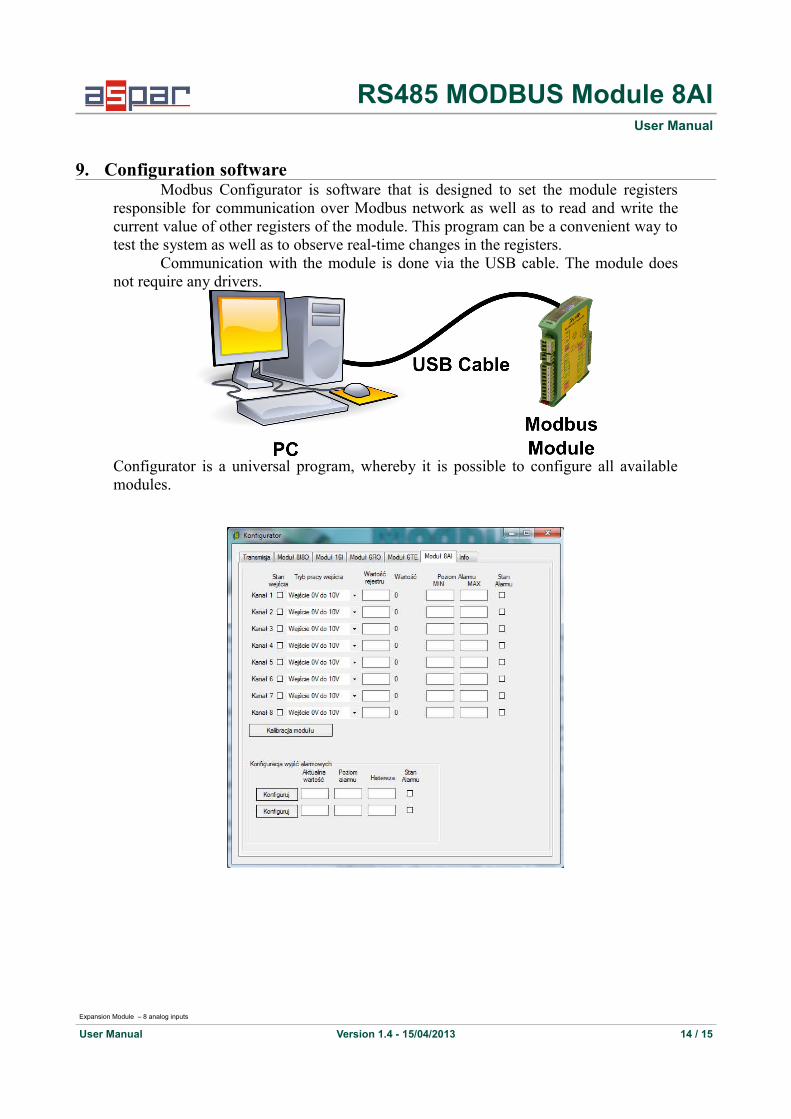
9. Configuration softwareModbus Configurator is software that is designed to set the module registers
responsible for communication over Modbus network as well as to read and write thecurrent value of other registers of the module. This program can be a convenient way totest the system as well as to observe real-time changes in the registers.
Communication with the module is done via the USB cable. The module doesnot require any drivers.
Configurator is a universal program, whereby it is possible to configure all availablemodules.
Expansion Module – 8 analog inputs
User Manual Version 1.4 - 15/04/2013 14 / 15

RS485 MODBUS Module 8AIUser Manual
Table of Content1. Safety rules.......................................................................................................................................32. Module Features...............................................................................................................................3
2.1. Purpose and description of the module.....................................................................................32.2. Technical Specifications...........................................................................................................42.3. Dimensions of the product........................................................................................................5
3. Communication configuration..........................................................................................................63.1. Grounding and shielding...........................................................................................................63.2. Network Termination................................................................................................................63.3. Setting Module Address in RS485 Modbus Network...............................................................63.4. Types of Modbus Registers.......................................................................................................73.5. Communication settings...........................................................................................................7
3.5.1. Default settings.................................................................................................................73.5.2. Restore the default configuration......................................................................................73.5.3. Configuration registers......................................................................................................8
4. Indicators..........................................................................................................................................85. Module Connection..........................................................................................................................96. Switches..........................................................................................................................................107. Modules Registers..........................................................................................................................11
7.1. Registered access....................................................................................................................117.2. Bit access................................................................................................................................13
8. Configuration software...................................................................................................................14
Manufactured for:Aspar s.c.
ul. Kapitańska 981-331 Gdynia
Poland
tel. +48 58 351 39 89; +48 58 732 71 73
Expansion Module – 8 analog inputs
User Manual Version 1.4 - 15/04/2013 15 / 15

Input NoVoltageinput
(default)
Currentinput
1
2
3
4
5
6
7
8