rs series user manual - eaw: eastern acoustic works
TRANSCRIPT
RS Series User Manual

1
IMPORTANT SAFETY INSTRUCTIONS - READ THIS FIRST Safety Instructions
Read and heed all warnings and safety instructions in this manual before using this product. Failure to follow these precautions may result in damage, injury, or death.
1) Read these instructions.
2) Keep these instructions.
3) Heed all warnings.
4) Follow all instructions.
5) Do not use this apparatus near water.
6) Clean only with a dry cloth.
7) Do not block any amplifier ventilation openings. Install in accordance with the manufacturer's instructions.
8) Do not install near any heat sources such as radiators, heat registers, stoves, or other apparatus that produce heat.
9) Do not defeat the safety purpose of the polarized or grounding-type plug. A polarized plug has
two blades with one wider than the other. A grounding type plug has two blades and a third grounding prong. The wide blade or the third prong is provided for your safety. If the provided plug does not fit into your outlet, consult an electrician for replacement of the obsolete outlet.
10) Protect the power cord from being walked on or pinched particularly at plugs, convenience receptacles and the point where they exit from the apparatus.
11) Only use attachments/accessories specified by the manufacturer.
12) Use only with the Caster Pallets and accessories specified by the manufacturer or sold with the
apparatus. When a Caster Pallet is used, use caution when moving the apparatus combination to avoid injury from tip-over.
13) Unplug this apparatus during lightning storms or when unused for long periods of time.
14) Refer all servicing to qualified service personnel. Servicing is required when the apparatus has
been damaged in any way, such as power-supply cord or plug is damaged, liquid has been
2
spilled or objects have fallen into the apparatus, does not operate normally, or has been dropped.
15) DO NOT ATTEMPT TO OPEN THE AMPLIFIER ITSELF; IT IS NOT USER-SERVICEABLE.
i. WARNING: The loudspeaker is supplied with an AC mains power cable. Depending on the voltage model ordered, this cable is configured with the most common ac mains connector for that voltage. If the connector is not compatible with the local ac mains receptacle, employ a licensed electrician to re-configure the cable with the proper connector. Ensure that ac power supply has a properly grounded safety ground. Failure to follow this warning could cause equipment damage, injury, or death.
FCC Compliance
This equipment has been tested and found to comply with the limits for a Class A digital device, pursuant to Part 15 of the FCC Rules (pending). These limits are designed to provide reasonable protection against harmful interference when the equipment is operated in a commercial environment. This equipment generates, uses, and can radiate radio frequency energy and, if not installed and used in accordance with the instruction manual, may cause harmful interference to radio communications. Operation of this equipment in a residential area is likely to cause harmful interference in which case the user will be required to correct the interference at his own expense.
CAUTION: Changes or modifications not expressly approved by EAW could void the user's authority to operate the equipment. The normal function of the product may be disturbed by Strong Electro Magnetic Interference. If so, simply reset the product to resume normal operation by following this instruction manual. If the product does not resume normal operation, please use the product in another location. WARNING: Operation of this product in a residential environment could cause radio interference.
Correct Disposal of this Product This symbol indicates that this product should not be disposed of with your household waste, according to the WEEE Directive (2002/96/EC) and your national law. This product should be handed over to an authorized collection site for recycling waste electrical and electronic equipment (WEEE). Improper handling of this type of waste could have a possible negative impact on the environment and human health due to potentially hazardous substances that are generally associated with WEEE. At the same time, your cooperation in the correct disposal of this product will contribute to the effective usage of natural resources. For more information about where you can drop off your waste equipment for recycling, please contact your local city office, waste authority, or your household waste disposal service.
3
Table of Contents IMPORTANT SAFETY INSTRUCTIONS - READ THIS FIRST ............................................................................................1
FCC Compliance ..........................................................................................................................................................2
Correct Disposal of this Product .................................................................................................................................2
RS™ System Overview ................................................................................................................................................5
RS Two-Way Point Source ..................................................................................................................................5
RS Subwoofers ....................................................................................................................................................6
Unpacking ...................................................................................................................................................................7
Contents .....................................................................................................................................................................7
Functions and Operations ..........................................................................................................................................8
RS 121, 123, 151, 153 Rear Input Panel Diagram ...............................................................................................8
RS115 Rear Input Panel Diagram ..................................................................................................................... 10
RS118 Rear Input Panel Diagram ..................................................................................................................... 12
Audio Connections .................................................................................................................................................. 13
Analog Audio ................................................................................................................................................... 13
AC Mains Connection .............................................................................................................................................. 14
Linking power (only on RS 123/153 Models) ................................................................................................... 14
Operating Indicators ................................................................................................................................................ 15
Operating Limits .................................................................................................................................................. 15
Adjusting the Output Level .................................................................................................................................. 16
Onboard Processing & Voicing ................................................................................................................................ 16
Voicing Options................................................................................................................................................ 16
Main ................................................................................................................................................................. 16
Monitor ............................................................................................................................................................ 16
EAW DSP Innovations .............................................................................................................................................. 17
DynO™ ............................................................................................................................................................. 17
EAW Focusing™ ............................................................................................................................................... 17
RS Application Configurations ................................................................................................................................. 18
Rotating the horn ............................................................................................................................................ 18
Application Notes .................................................................................................................................................... 19
Flying RS from threaded mounting points .......................................................................................................... 19
Using RS as a Stage Monitor ................................................................................................................................ 19
4
Using Pole Mount with RS (on tripod or RS subwoofer) ..................................................................................... 19
Rigging ..................................................................................................................................................................... 20
Basic Field Troubleshooting & Repair ...................................................................................................................... 21
Rigging Problems ................................................................................................................................................. 22
Enclosure and Integral Hardware ........................................................................................................................ 22
Cosmetics............................................................................................................................................................. 22
Driver Service....................................................................................................................................................... 22
Powered Loudspeaker Electronics ...................................................................................................................... 23
Internal Electronics and Wiring ........................................................................................................................... 23
Electrical Warnings .................................................................................................................................................. 23
AC MAINS SUPPLY ............................................................................................................................................... 23
Operating Temperature....................................................................................................................................... 23
General Service .................................................................................................................................................... 24
Rigging Service ..................................................................................................................................................... 24
Routine Maintenance .......................................................................................................................................... 24
Internal Electronics and Wiring ........................................................................................................................... 24
Contacting EAW ....................................................................................................................................................... 25
Operating Questions ........................................................................................................................................... 25
Service Information ............................................................................................................................................. 25
5
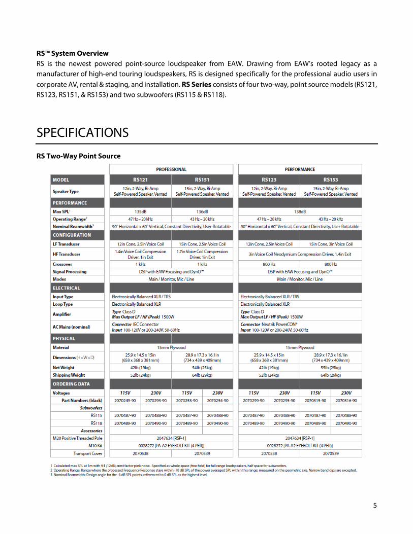
RS™ System Overview RS is the newest powered point‐source loudspeaker from EAW. Drawing from EAW’s rooted legacy as a manufacturer of high‐end touring loudspeakers, RS is designed specifically for the professional audio users in corporate AV, rental & staging, and installation. RS Series consists of four two-way, point source models (RS121, RS123, RS151, & RS153) and two subwoofers (RS115 & RS118).
SPECIFICATIONS
RS Two-Way Point Source
6
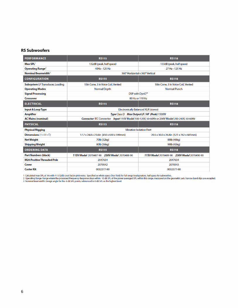
RS Subwoofers
7
Unpacking You should have visually inspected the outside of the shipping carton and noted any damage on the shipping bill you signed. After unpacking, if you find concealed damage to the loudspeaker, save the packing materials for the carrier's inspection, notify the carrier immediately and file a shipping damage claim.
Although EAW will help in any way possible, it is always the responsibility of the receiving party to file any shipping damage claim. The carrier will help prepare and file this claim.
Contents Qty Item 1 RS Series Product 1 Power Cables
• RS Models 121/151: IEC to Edison • RS Models 123/153: Powercon to Edison
1 Warranty Card

8
Functions and Operations
RS 121, 123, 151, 153 Rear Input Panel Diagram
1. Level (Gain) Control Adjusts the level of the INPUT signal. Turning counterclockwise will reduce the output level and turning clockwise will raise the overall output level of the speaker.
2. XLR Input Connector Balanced XLR input connector for analog input signal.
3. XLR Thru (Output) Connector Balanced XLR output connector to daisy-chain input signal to other speakers. This signal comes directly from the input signal and is unaltered by speaker’s internal processing.
4. Balanced TRS Connector Balanced 1/4” TRS input connector for analog input signal.
5. Line/Mic Switch This switch controls the input sensitivity. For low-voltage signals, such as from a microphone, set the switch to the MIC position. For high-voltage signals, such as from a mixing console, set the switch to the LINE position. NOTE: Utilizing the MIC switch position with a high-voltage signal may cause damage to your speaker – be sure to use the proper switch settings based on the incoming signal strength.

9
6. Main/Monitor Button
This button is used to toggle between the speaker’s two pre-defined voicings – MAIN and MONITOR. The MAIN voicing should be chosen when the speaker is placed on a tripod or installed. The MONITOR voicing should be chosen when the speaker is placed on the floor or at its monitor angle – this setting reduces the impact of low frequency floor coupling that occurs when a speaker is placed on the floor, providing a cleaner and more coherent output.
7. Status LED Indicator The status indicator will remain lit if the speaker is in functioning condition. If the light blinks, it indicates that the speaker has entered temperature protection mode and must be cooled down and power-cycled before it will function normally.
8. Signal LED Indicator The status indicator will turn green when an input signal is detected. NOTE: Low-voltage signals may not be able strong enough to trigger the LED indicator, but may still be heard from the speaker – this is perfectly fine.
9. Limit LED Indicator The limit indicator will turn red when the output has reached its maximum level. If the LED blinks occasionally, EAW DynO™ will optimize the output and continue to provide clear output at its maximum volume. If the LED blinks frequently or is lit continuously, reduce the level control (1) to prevent output distortion. NOTE: Only one signal input may be used at a time (2 or 4) – using both at the same time will result in a distorted signal.

10
RS115 Rear Input Panel Diagram
1. Level (Gain) Control Adjusts the level of the INPUT signal. Turning counterclockwise will reduce the output level and turning clockwise will raise the overall output level of the speaker.
2. XLR Input Connector Two balanced XLR input connectors for analog input signal.
3. XLR Thru/Xover (Output) Connector Two balanced XLR output connector to daisy-chain input signal to other speakers. This signal can either come directly from the input connector (unaltered by the speaker’s internal processing), or high-passed at the XOVER frequency based on the position of the OUTPUT button (4).
4. Output Button This button is used to toggle the processing of the XLR THRU/XOVER output signal. Setting the button to THRU outputs a signal unaltered by the speaker’s internal processing, whereas setting the button to XOVER applies a high-pass filter to the output signal at the frequency determined by the XOVER button position (5). The button should be set to the THRU position if daisy-chaining to other subwoofers, or if connecting a full-range speaker that utilizes an external high-pass filter. The button should be set to XOVER if outputting directly to RS two-way speakers or if the connected full-range speaker does not have an integrated high-pass filter option.
11
5. Crossover Button This button is used to toggle between crossover frequencies – the two crossover frequency options are 80Hz and 100Hz.
6. Mode Button This button is used to toggle between the speaker’s two pre-defined voicings – Normal and Depth. Though normal mode is tuned for deep, robust bass, depth focuses on further boosting frequencies on the lower end of its frequency range.
7. Status LED Indicator The status indicator will remain lit if the speaker is in functioning condition. If the light blinks, it indicates that the speaker has entered temperature protection mode and must be cooled down and power-cycled before it will function normally.
8. Signal LED Indicator The status indicator will turn green when an input signal is detected. NOTE: Low-voltage signals may not be able strong enough to trigger the LED indicator, but may still be heard from the speaker – this is perfectly fine.
9. Limit LED Indicator The limit indicator will turn red when the output has reached its maximum level. If the LED blinks occasionally, EAW DynO™ will optimize the output and continue to provide clear output at its maximum volume. If the LED blinks frequently or is lit continuously, reduce the level control (1) to prevent output distortion.

12
RS118 Rear Input Panel Diagram
1. Level (Gain) Control Adjusts the level of the INPUT signal. Turning counterclockwise will reduce the output level and turning clockwise will raise the overall output level of the speaker.
2. XLR Input Connector Two balanced XLR input connectors for analog input signal.
3. XLR Thru/Xover (Output) Connector Two balanced XLR output connector to daisy-chain input signal to other speakers. This signal can either come directly from the input connector (unaltered by the speaker’s internal processing), or high-passed at the XOVER frequency based on the position of the OUTPUT button (4).
4. Output Button This button is used to toggle the processing of the XLR THRU/XOVER output signal. Setting the button to THRU outputs a signal unaltered by the speaker’s internal processing, whereas setting the button to XOVER applies a high-pass filter to the output signal at the frequency determined by the XOVER button position (5). The button should be set to the THRU position if daisy-chaining to other subwoofers, or if connecting a full-range speaker that utilizes an external high-pass filter. The button should be set to XOVER if outputting directly to RS two-way speakers or if the connected full-range speaker does not have an integrated high-pass filter option.
5. Crossover Button This button is used to toggle between crossover frequencies – the two crossover frequency options are 80Hz and 100Hz.

13
6. Mode Button
This button is used to toggle between the speaker’s two pre-defined voicings – Normal and Punch. Normal mode is tuned for deep, robust bass, whereas punch focuses on boosting frequencies on the upper-end of its frequency range, adding extra power to kick drums.
7. Status LED Indicator The status indicator will remain lit if the speaker is in functioning condition. If the light blinks, it indicates that the speaker has entered temperature protection mode and must be cooled down and power-cycled before it will function normally.
8. Signal LED Indicator The status indicator will turn green when an input signal is detected. NOTE: Low-voltage signals may not be able strong enough to trigger the LED indicator, but may still be heard from the speaker – this is perfectly fine.
9. Limit LED Indicator The limit indicator will turn red when the output has reached its maximum level. If the LED blinks occasionally, EAW DynO™ will optimize the output and continue to provide clear output at its maximum volume. If the LED blinks frequently or is lit continuously, reduce the level control (1) to prevent output distortion.
Audio Connections
Analog Audio Connect the output from your line-level signal source to either the XLR-3F INPUT or TRS connector on the rear panel. These are electronically balanced inputs. Only one of these connectors can be connected at a time – using both inputs at the same time will cause input distortion. Users must provide their own XLR/TRS cables. The two XLR-type connectors (one female and one male) and TRS connector on the rear of each RS series product are designed for professional audio signal levels, nominally 0 dB (= 0.775 V). Normally, use the female XLR or TRS as the signal input. Use the male XLR as a loop-thru output to connect the same signal input to additional RS products.
The XLR wiring convention is as
follows: Pin 1: Shield Pin 2: +/Hot Pin 3: -/Cold

14
The TRS wiring convention is as follows: Pin 1: Shield Pin 2: +/Hot Pin 3: -/Cold
AC Mains Connection Connect the supplied AC mains cord to the IEC connector (RS 121/151 Models) or Neutrik® powerCON® socket (RS 123/153 Models) on the rear of the loudspeaker. Connect the other end to an AC mains supply receptacle, nominally 115V 60Hz or 230V 50 Hz as labeled on the loudspeaker. If necessary, have a qualified electrician change the cable plug as required for compatibility with the local AC mains receptacle.
WARNING: Before connecting an RS loudspeaker to the AC mains supply, completely turn down the input signal to the loudspeaker using the input level attenuator. Failing to do say may result in excessive and possibly damaging sound pressure levels emanating from the loudspeaker when powered.
Linking power (only on RS 123/153 Models) The Neutrik® powerCON® AC mains and AC loop connectors are wired in parallel to provide an AC mains inlet and outlet on each RS product. The blue AC mains inlet mates with a Neutrik® powerCON® NACFC3A (supplied). The white AC mains outlet mates with a Neutrik® powerCON® NACFC3B. Therefore, to loop the AC mains from enclosure to enclosure, connect an AC mains jumper cable as shown (jumper is not included with RS series products).
Up to four additional RS 123/153 products can be looped in this fashion. Use an AC loop connector to daisy-chain AC mains power from one enclosure to another. The maximum, continuous load must not exceed 12A for the 115V version and 6A for the 230V version.
NOTE: The circuit breaker only protects the AC loop outlet, not the AC mains connector. If the continuous load connected to the AC loop outlet exceeds the rated load, the circuit breaker will trip. For this situation, reduce the connected load and then manually reset the circuit breaker.

15
Operating Indicators Please refer to the chart below to determine the current operating status based on the three LED indicators located on the rear-input panel of your RS unit.
Indication Condition Next Steps
LED Color/Repeat
Period
Status LED Green - Solid
All components working properly
None
Signal LED Green - Flashing/Solid
An input signal is being received by the amplifier.
None
Limiter LED
Red - Flashing The speaker is soft limiting. None
Red - Solid The speaker is clipping.
Reduce volume until the limit light only flashes occasionally.
ALL LEDs Flashing System Fault Contact EAW Support.
Limit The limiting parameters set in RS Products are engineered to provide a high level of protection for the drivers while maximizing sonic performance and output. The Limit indicator in the rear input panel illuminates when limiting is occurring. If this is flashing occasionally, meaning no more than once every 3 seconds or so, then levels are probably OK, but at maximum if this indicator is flashing more than once every 3 seconds or so, reduce the input signal level.
CAUTION: Electronic limiters cannot provide absolute protection against driver failure. Thus, if limiting is occurring, it is a warning that excessive signal levels are being approached. EAW is not responsible for damaged or broken speaker components due to user error.
Operating Limits The RS products have a Limiter indicator. The speaker is designed to maximize performance and clarity at limit – if the limit light is blinking every few seconds, no action is needed. If the limit light is flashing more frequently, or is continuously on, reduce the volume to avoid distortion.

16
Adjusting the Output Level
Starting with the input level attenuator at -∞ (all the way to the left), turn the input attenuator up until
the desired volume is reached, but below the point where the Limiter light illuminates.
Onboard Processing & Voicing
Voicing Options RS features two distinct voicings on two-way to accommodate select applications. To select voicings, simply press the ‘Mode’ button on the back panel until the button position is identical to that of the desired voicing position depicted to the right of the button.
Main Select the ‘Main’ voicing when using RS speakers on a tripod or hung for installation.
Monitor Select the ‘Monitor’ voicing when using the speaker as a floor wedge monitor. It’s designed to reduce floor coupling of low frequencies, providing a clean and accurate bass response.

17
EAW DSP Innovations
DynO™ DynO™ is a revolutionary processing technique that allows EAW Engineers to maximize output from a given amplifier – transducer combination. As opposed to conventional limiting which simply views amplifier output and driver power handling in aggregate (i.e. a driver can handle 100 watts or an amplifier can produce 500 watts), the DynO process involves much more detail and complexity. By studying the headroom of all electronic and acoustical devices frequency by frequency and utilizing frequency‐dependent limiting algorithms in combination with more traditional band-pass limiting, a system’s broadband headroom can be maximized regardless of the input signal spectrum.
EAW Focusing™ Even in well-designed professional loudspeakers, inherent sonic flaws such as phase plug reflections, horn resonances and cone resonances can cause undesirable audible artifacts. Implemented through advanced digital signal processing, EAW Focusing™ generates complex filters that correct these imperfections and improve the transient response of a loudspeaker. This is accomplished by isolating linear, time invariant and spatially consistent anomalies in a loudspeaker’s response and eliminating them through advanced processing. The result is a high output, controlled loudspeaker that provides a pristine transient response equal to that of a direct radiating studio monitor.
18
RS Application Configurations
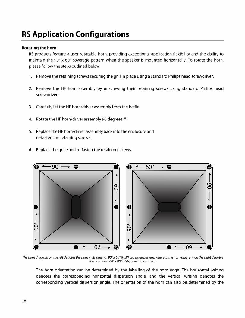
Rotating the horn RS products feature a user-rotatable horn, providing exceptional application flexibility and the ability to maintain the 90o x 60o coverage pattern when the speaker is mounted horizontally. To rotate the horn, please follow the steps outlined below.
1. Remove the retaining screws securing the grill in place using a standard Philips head screwdriver.
2. Remove the HF horn assembly by unscrewing their retaining screws using standard Philips head screwdriver.
3. Carefully lift the HF horn/driver assembly from the baffle
4. Rotate the HF horn/driver assembly 90 degrees. *
5. Replace the HF horn/driver assembly back into the enclosure and re-fasten the retaining screws
6. Replace the grille and re-fasten the retaining screws.
The horn diagram on the left denotes the horn in its original 90° x 60° (HxV) coverage pattern, whereas the horn diagram on the right denotes the horn in its 60° x 90° (HxV) coverage pattern.
The horn orientation can be determined by the labelling of the horn edge. The horizontal writing denotes the corresponding horizontal dispersion angle, and the vertical writing denotes the corresponding vertical dispersion angle. The orientation of the horn can also be determined by the
19
orientation of the horn throat opening. When the opening is in the vertical orientation, the horn is in the default 90o x 60o configuration. If the opening is horizontal, the horn is in the 60o horizontal x 90o vertical orientation.
Application Notes
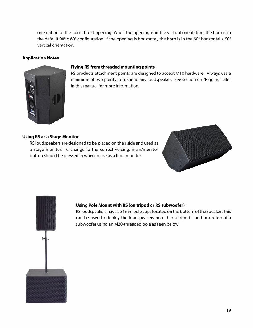
Flying RS from threaded mounting points RS products attachment points are designed to accept M10 hardware. Always use a minimum of two points to suspend any loudspeaker. See section on “Rigging” later in this manual for more information.
Using RS as a Stage Monitor RS loudspeakers are designed to be placed on their side and used as a stage monitor. To change to the correct voicing, main/monitor button should be pressed in when in use as a floor monitor.
Using Pole Mount with RS (on tripod or RS subwoofer) RS loudspeakers have a 35mm pole cups located on the bottom of the speaker. This can be used to deploy the loudspeakers on either a tripod stand or on top of a subwoofer using an M20-threaded pole as seen below.

20
Rigging RS series products are intended to be suspended via integral rigging points, or ground-stacked. RS subwoofers are intended to be ground-stacked only. It is the user’s responsibility to determine the viability and safety for alternate methods and implement them accordingly. NOTE: At a minimum, any suspended RS loudspeaker must be flown from the two top M10 rigging points. The third point on the rear of the enclosure may be used to increase the down-tilt. Always observe load de-rating when applying loads with lateral components to eyebolts. Use hoist rings where necessary. NEVER SUSPEND ONE RS ENCLOSURE FROM ANOTHER – ALL FLOWN ENCLOSURES MUST BE SUPPORTED INDEPENDENTLY.
WARNING: Mounting or overhead suspension of any heavy load can result in serious injury and equipment damage. This work should be done by qualified persons following safe rigging practices in accordance with all applicable safety and construction standards. Such persons must determine the required load ratings and design factors. They must determine the mounting or suspension method that meets static, dynamic, shock, and any other load requirements. All such work must be done in accordance with and in compliance with all federal, state, and local regulations governing such work. WARNING: If there is any question about the integrity or capability of any part to perform its intended function when used to suspend or mount a loudspeaker, immediately remove it from service for repair or replacement. WARNING: Do not under any circumstances use a loudspeaker's handles to support the weight of the loudspeaker except for their intended use: hand carrying. The handles are not rated to support the load of the loudspeaker for temporary or permanent installation. WARNING: Rigging loudspeakers is an extremely serious matter with potentially lethal consequences should anything go wrong. It is of vital importance that this task is done by persons qualified to do so and who have a full understanding of all factors involved, with safety as the number one priority. Only persons with the knowledge of and experience with proper hardware and safe rigging techniques should attempt to suspend or mount loudspeaker systems overhead. For all questions involving loudspeaker rigging, consult a licensed, qualified professional Engineer or Professional Rigger. All rigging work must be done in accordance with and in compliance with all applicable regulations governing such work.

21
Basic Field Troubleshooting & Repair Issue Potential Causes Potential Solutions
Power Won't Turn On
Speaker is not connected to a power source
Connect speaker to power source using a properly-rated power cable.
Speaker power cable is not connected properly or faulty.
Swap power cable with a known-good cable. Replug cable into speaker power connector.
Power Shuts Off Suddenly Speaker fuse blown. Replace fuse.
No Sound
Speaker is not turned on. Turn on speaker.
Input cable is not connected properly or faulty.
Swap cable with a known-good cable. Replug cable into signal input connector.
No signal. Check signal source.
Input signal is too low.
Increase the gain at the signal source or using the level knob. If using a microphone as a source, be sure the Mic/Line switch is set to Mic position.
Level knob is set too low. Slowly increase the input gain by turning the level knob clockwise.
Distorted Sound
Speaker limiting Check limit light – if the limit light is blinking frequently or statically lit, reduce volume levels accordingly.
Input signal clipping Make sure input signal source is not being overdriven
Hum/Buzz Sound
Ground loops, A/C grounding issues Remove signal ground
Signal input cable is unbalanced and too long. Use a balanced cable or a shorter unbalanced cable

22
Feedback/Howling when using Microphone
Microphone position with respect to speaker is producing a feedback loop.
Move/point microphone away from speaker.
Reduce microphone gain.
If the suggested solutions do not fix the problem, please contact EAW Applications Engineering (see final page of manual for contact.)
Rigging Problems Because of the potential serious consequences and liabilities due to faulty rigging, contact the EAW Service Department to determine the appropriate service solution for any problems with the rigging hardware integral to the enclosure or EAW rigging accessories. Enclosure and Integral Hardware Enclosure problems, such as loose hardware, faulty joints, or other structural problems, will usually be heard as distinct buzzes, rattles, or other unwanted noises. To test for enclosure problems, use a sine wave signal manually swept on the loudspeaker. The input level should be varied, because certain problems can be level as well as frequency specific. It may be possible to field-repair some enclosure problems.
Cosmetics While the paint finish and the wood used for the enclosures is of high quality and durability, scuffs, marks, and other blemishes may appear from normal handling. For paint touchup, use good quality latex paint. For a more permanent and cosmetically correct appearance, contact the EAW Service Department for the paint specifications or to purchase small quantities for touch-up. For cosmetically damaged wood, use common woodworking methods and materials as appropriate for the damage.
Driver Service A faulty driver will usually cause readily audible distortions or other unwanted noises. In other cases, they may stop functioning. Use your ears and test signals or other sound source to determine which one is at fault. The drivers can be field serviced by replacing the entire driver or having the driver repaired (such as diaphragm replacement) by a qualified service technician.
1. Access the drivers by removing the front grille.
2. Remove the LF driver of HF horn/driver assembly by unscrewing their retaining screws.
3. Lift the LF driver or HF horn/driver assembly from the baffle.
4. Disconnect the signal cable from the driver.
23
5. To reinstall or replace the LF driver and/or the HF horn/driver assembly, reverse the above steps. Make sure the LF driver is connected with the blue+ and black- signal wires and the HF driver is connected with the red (+) and black (-) signal wires.
IMPORTANT: When reconnecting the signal wires to the driver, connect the colored wire to the plus (+) terminal and the black wire to the (-) minus terminal.
Powered Loudspeaker Electronics Some faults with the electronics will normally be indicated by the ‘Status’ indicator on the loudspeaker input panel and are described in the section labeled ‘Operating Indicators’. Others should clearly be indicated by an outright malfunction in the sound output. Such malfunctions can include:
1. No or very low sound output
2. Highly distorted sound
3. Poor frequency response, such as the loss of low or high frequencies
4. Intermittent sound
5. Excessive electronic noise In the case of malfunctioning electronics, contact the EAW Parts Department for troubleshooting and repair instructions.
Internal Electronics and Wiring Faulty electronics are serviced by replacing the entire amplifier module. A replacement module consists of the power amplifiers, DSP board, power supply, connectors and indicators, all pre-mounted on the amplifier panel. See ‘Swapping Amplifier Modules’ above for amplifier replacement instructions.
Electrical Warnings
AC MAINS SUPPLY WARNING: Read all instruction and cautionary notes concerning electrical power in the EAW Loudspeaker Owner’s Manual.
Operating Temperature The operating temperature range is 32° F to 113° F / 0°C to 45° C. NOTE: When in operation and under load, maintain at least 6 inches of clearance below and 36 inches of clearance behind all fan inlets and outlets.
24
Service, Inspection & Maintenance
General Service All components in the RS systems are designed to withstand the most rigorous and demanding environments. Through regular operation it may still be necessary to replace acoustical, electronic and mechanical components. The section below offers guidelines for user-serviceable parts. If you have any questions about replacing components in RS series products, please contact EAW Service immediately and before performing the replacement. CAUTION: These servicing instructions are for use by qualified service personnel only. To reduce the risk of electric shock, do not perform any servicing other than that contained in the operating instructions unless you are qualified to do so.
Rigging Service Because of the potential serious consequences and liabilities due to faulty rigging, contact EAW to determine the appropriate service solution for any rigging hardware concerns.
Routine Maintenance DO NOT ATTEMPT TO OPEN, REPAIR OR SERVICE THE POWER PLANT; IT IS NOT USER-SERVICEABLE.
Internal Electronics and Wiring The RS Amplifier Module is not user-serviceable and must be sent to EAW for repair. In the unlikely event of a failure of any amplifier or processing components, simply remove and replace the entire Amplifier Module with a spare. DO NOT ATTEMPT TO OPEN, REPAIR OR SERVICE THE AMPLIFIER MODULE.
25
Contacting EAW We have attempted to make this manual as thorough as possible. However, feel free to contact us with any further questions or comments for topics not covered.
Operating Questions EAW Applications Engineering Tel 508-234-6158 Tel 800-992-5013 (USA only) e-mail [email protected]
Service Information EAW® Service Department One Main Street Building 9 Whitinsville, MA 01588 USA Tel 508-234-6158 x3 Tel 800-992-5013 (USA only) e-mail [email protected]

26
Warranty Information
Eastern Acoustic works (EAW) warrants its products for these periods starting from the date of delivery to the owner from an authorized dealer or authorized EAW distributor. Loudspeakers 6 years; Weather Protected (WP) Loudspeakers 5 years; Active Electronics 2 years; Accessories 2 years. WHAT IS COVERED: During the applicable warranty period, EAW warrants the product against defects in workmanship and materials and against malfunctions. EAW will remedy all such defects and malfunctions without charge for parts or labor if the warranty applies. Final determination of warranty coverage lies solely with EAW.
WHAT IS NOT COVERED: 1. This warranty does not extend to damage or malfunctions resulting from, but not limited to, shipment, improper installation, misuse, neglect, abuse, normal wear, accident, or to any product on which the serial number has been modified or removed. 2. Exterior defects in or damage to the exterior appearance are specifically excluded from this warranty. 3. EAW shall not be liable for incidental or consequential damages resulting from the use of this product. 4. Repairs and/or modifications by other than EAW or an authorized EAW distributor automatically void this warranty.
OBTAINING WARRANTY SERVICE: 1. Obtain a factory Return Authorization (RA) number (required) by contacting the EAW Service Department. 2. Write the RA number so it is prominently displayed on the outside of the shipping carton. Any products received without an assigned RA number that is clearly visible upon arrival at the factory will be refused. 3. Enclose a proof of the original delivery date or a copy of the original sales receipt. 4. Enclose a description of the suspected defect or malfunction and the conditions, if any, which caused the problem. 5. Return the product to EAW or to an authorized EAW distributor.
WARRANTY SHIPPING: 1. You are responsible for prepaying shipping costs F.O.B. EAW, Whitinsville or to an authorized EAW distributor. 2. Shipping products must be properly packaged. Where possible, use the original shipping carton and packing materials. If the original shipping carton cannot be used, contact EAW to send you a new carton, for which there will be a small charge. 3. EAW will not be responsible for damage resulting from inadequate packing. Any units received damaged due to improper packaging will be deemed out of warranty. 4. If the product is found to be under warranty, EAW will prepay return shipping costs for standard, ground transportation. If you need expedited shipping, you will be charged for this.
YOUR WARRANTY RIGHTS: This warranty is exclusive, and no other warranty is expressed or implied. You have specific legal rights under this warranty. You may have additional rights that are specific to your region. Additionally, the applicability of certain provisions or this warranty may vary for your region. In no event shall this warranty affect your statutory rights. Contact EAW, your local EAW distributor, or EAW dealer for any additional information.

©2021 Eastern Acoustic WorksAll rights reserved. Products are not drawn to scale.
All terms, conditions, and specifications subject to change without notice. RD3004 (C00)
Eastern Acoustic WorksOne Main Street | Whitinsville, MA 01588 | USA
tel 800 992 5013 / +1 508 234 6158www.eaw.com