rp7400 hardware manual - apache welcome pageh20628. · do not recharge, disassemble, or dispose of...
TRANSCRIPT

rp7400 Hardware Manual
y of HP.
Notice© Copyright 2002-2010 Hewlett-Packard Development Company
Hewlett-Packard makes no warranty of any kind with regard to this material, including but not limited to, the implied warranties of merchantability and fitness for a particular purpose. Hewlett-Packard shall not be liable for errors contained herein or for incidental or consequential damages in connection with the furnishing, performance, or use of this material.
Hewlett-Packard assumes no responsibility for the use or reliability of its software on equipment that is not furnished by Hewlett-Packard.
All rights are reserved. No part of this document may be photographed, reproduced, or translated to another language without prior written consent of Hewlett-Packard Company.
The information contained in this document is subject to change without notice.
HP welcomes your feedback. To make comments and suggestions about product documentation,
send a message to [email protected].
Include the document title and manufacturing part number. All submissions become the propert
2
What’s New?
What’s New?Visit this page to find out what new information has been released since the last web site publish (August, 2001) and CD-ROM on August, 2001. The additions and modifications to the web site listed here are effective as of March, 2010.
New Sections On the Web Site:
• System upgrade instructions for the PA8700 upgrade.
Modified Sections On the Web Site:
• Identified changes to all sections as applicable to HP e3000.
The current version of the Customer CD-ROM was released August, 2002.
The web site will be identical to the CD-ROM on September, 2002.
NOTE All references to rp74xx are equally applicable to the HP e3000.
3

What’s New?
4
System Overview
rs-docs
The following sections provide or point to an overview of the rp7400 server hardware and software.
Hardware overview
For an overview of the Enterprise Server Family hardware go to http://www.hp.com/go/hp9000_servers-docs
For an overview of the HP-9000 or HP e3000 rp7400 Server hardware go to http://www.hp.com/go/hp9000_serve
Software Overview
The HP-9000 rp7400 server is designed to operate using HP-UX version 11.0 or newer.
The HP e3000 rp7400 is designed to operate using MPE/iX release 7.0 (uni-processor support) and MPE/iX release 7.0 express (multi-processor support).
NOTE All references to rp7400 are equally applicable to the HP e3000 and n4000.
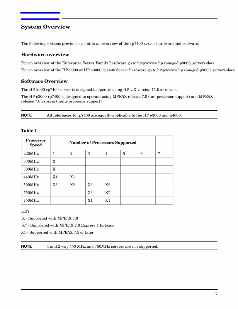
KEY:
X - Supported with MPE/iX 7.0
X* - Supported with MPE/iX 7.0 Express 1 Release
X1 - Supported with MPE/iX 7.5 or later
NOTE 1 and 2 way 550 MHz and 750MHz servers are not supported.
Table 1
Processor Speed Number of Processors Supported
220MHz 1 2 3 4 5 6 7
330MHz X
380MHz X
440MHz X1 X1
500MHz X* X* X* X*
550MHz X* X*
750MHz X1 X1
5

System Overview
6

rp7400 Enterprise Server System Safety and Regulatory Information
rp7400 Enterprise Server System Safety and Regulatory Information
Overview
Regulatory Compliance statements are required by some countries for international importation of rp7400 Enterprise Servers. The following information is provided:
Regulatory Information
Electrical Safety
— Electrostatic Discharge (ESD) Precautions
— Battery Notice
Cabinet Safety Precautions
Declaration of Conformity
FCC Statement (USA Only)
Canada RFI Statement
European Union RFI Statement
Korean RFI Statement
Taiwan RFI Statement
Japan Safety and Regulatory Statements
Acoustics (Germany)
Australian C-Tick Label
Laser Safety
Product Information
For detailed information on the rp7400 Enterprise Server product, see the following web site:http://www.hp.com/go/hp9000_servers-docs (in the Systems Hardware selection).
7
rp7400 Enterprise Server System Safety and Regulatory Information
Regulatory Information
For your protection, this product has been tested for conformance to various national and international regulations and standards. The scope of this regulatory testing includes electrical and mechanical safety, electromagnetic emissions, immunity, acoustics and hazardous materials.
When required, approvals are obtained from third party test agencies. Approval marks appear on the product label. In addition, various regulatory bodies require some information under the headings listed in this section.
Electrical Safety
This product has not been evaluated for connection to an “IT” power system (AC distribution system having no direct connection to earth according to IEC 950).
Locate the AC outlet near the computer! The AC power cords are this product's main AC disconnect devices and must be easily accessible at all times.
Electrostatic Discharge (ESD) Precautions
When handling any electronic component or assembly (such as, a PCI card or Memory SIMM), you must observe the following antistatic precautions to prevent damage. An ESD kit (HP P/N A3024-80004) is available (or supplied with Memory additions). This kit contains one wrist strap, one conductive sheet, and one anti-static foam pad.
• Always wear a grounded wrist strap when working around the system, and when handling printed circuit boards.
• Treat all assemblies, components and interface connections as static-sensitive.
• Avoid working in carpeted areas, and keep body movement to a minimum while removing or installing boards, to minimize buildup of static charge.
Battery Notice
This product contains a Lithium battery.
This battery is not to be removed or replaced by the user. If the battery needs to be replaced, contact your Hewlett-Packard authorized service personnel.
CAUTION Lithium batteries may explode if mistreated. Do not recharge, disassemble, or dispose of in a fire.
Please properly recycle all used batteries.
8
rp7400 Enterprise Server System Safety and Regulatory Information
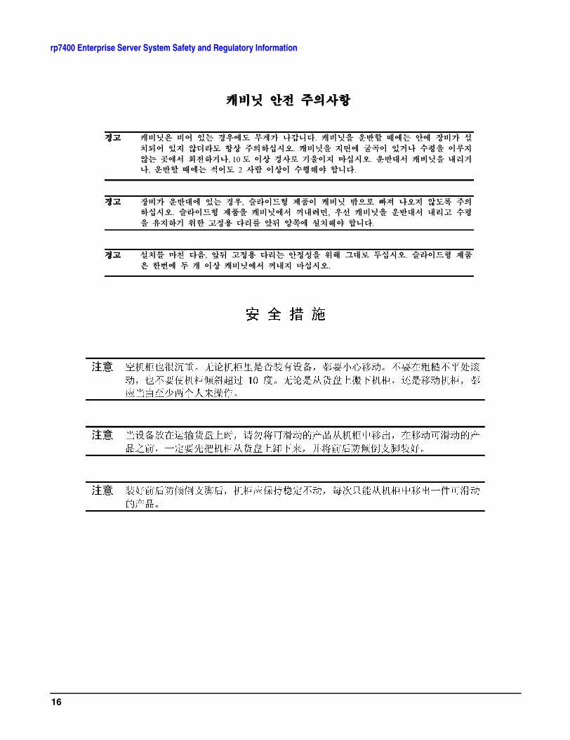
Cabinet Safety Precautions
WARNING Cabinets are heavy even when empty. Exercise caution when moving cabinets whether equipment is installed in the cabinet or not. Avoid rolling cabinets on rough or uneven surfaces or inclines greater than 10 degrees. Unloading cabinets from the pallet and movement of cabinets should be performed by at least two people.
WARNING Slideable products are not to be extended from the cabinet while the equipment is on the shipping pallet. The cabinet must be unloaded from the pallet and both front and rear anti-tip feet properly installed prior to extending any slideable product.
WARNING Once installed, both the front and rear anti-tip feet must remain in place to maintain stability. Only one slideable product must be extended at a time.
Sicherheitsvorkehrungen für Einbaugehäuse
WARNING Einbaugehäuse haben auch ohne Inhalt ein hohes Gewicht. Seien Sie also vorsichtig, wenn Sie ein Gehäuse hin und her bewegen, sei es mit oder ohne installierten Innenteilen. Rollen Sie das Gehäuse nach Möglichkeit nicht über rauhe oder unebene Oberflächen bzw. Oberflächen mit mehr als 10 Grad Neigung. Das Abladen von der Palette und Positionieren muß von mindestens zwei Personen durchgeführt werden.
WARNING Ziehen Sie keine beweglichen Teile heraus, solange sich das Einbaugehäuse auf der Palette befindet. Laden Sie es zunächst von der Palette ab, und stellen Sie es mit den kippsicheren Vorder-und Hinterfüßen ordnungsgemäß auf, um bewegliche Teile sicher herausziehen zu können.
WARNING Nach deren Installation dürfen die kippsicheren Füße nicht wieder entfernt werden, um sicheren Stand zu gewährleisten. Ziehen Sie jeweils nur ein bewegliches Teil heraus.
9
rp7400 Enterprise Server System Safety and Regulatory Information
Consignes de sécurité relatives aux armoires
WARNING Une armoire est lourde même lorsqu’elle est vide. Faites preuve de prudence lorsque vous en déplacer une, peu importe si des éléments y sont installés ou non. Évitez de faire rouler l’armoire sur un sol irrégulier ou incliné à plus de 10 degrés. Il faut au moins deux personnes pour décharger une armoire de la palette d’expédition et la déplacer.
WARNING Ne faites pas glisser les éléments coulissants hors de l’armoire alors qu’elle se trouve sur la palette d’expédition. Vous devez d’abord décharger l’armoire de la palette et installer correctement les pieds antibasculement, en avant et en arrière, avant de faire glisser les éléments coulissants.
WARNING Lorsqu’ils sont installés, les pieds antibasculement situés à l’avant et à l’arrière doivent tous deux rester en place pour assurer la stabilité de l'armoire. Vous ne devez faire glisser hors de l’armoire qu’un seul élément coulissant à la fois.
Medidas de seguridad para armarios
WARNING Los armarios son pesados aun cuando estén vacíos. Tenga cuidado cuando mueva los armarios independientemente de que haya equipo instalado en el armario o no. Evite desplazar los armarios sobre superficies rugosas o disparejas o pendientes de más de 10 grados. Dos personas, como mínimo, tienen que realizar la descarga de los armarios de la plataforma de carga y mover los armarios.
WARNING Los productos deslizables no deben extenderse del armario cuando el equipo se encuentre en la plataforma de carga. Se debe descargar el armario de la plataforma e instalar bien las punteras delanteras y traseras de protección antes de extender cualquier producto deslizable.
WARNING Una vez instalado, se deberán dejar puestas las punteras de protección, delanteras y traseras, para mantener la estabilidad. Se deberá extender un solo producto deslizable cada vez.
10
rp7400 Enterprise Server System Safety and Regulatory Information
Procedimentos de Segurança - Armários
WARNING Os armários são pesados, mesmo quando vazios. Tenha cuidado ao movimentar os armários, quer haja equipamentos instalados quer não. Evite deslizar os armários sobre superficies acidentadas, irregulares ou com inclinação superior a 10 graus. A retirada dos armários do palete e sua movimentação deverão ser feitas por, no mínimo, duas pessoas.
WARNING Partes deslizantes não deverão ser abertas enquanto o armário encontrar-se no palete de embarque. O armário deve ser descarregado do palete e os anteparos nos pés dianteiros e traseiros devem ser instalados adequadamente antes de se abrir qualquer parte deslizante.
WARNING Uma vez instalados, tanto os anteparos nos pés dianteiros quanto nos traseiros devem permanecer em seus lugares adequados para garantir a estabilidade da peça. Deve-se abrir apenas uma parte deslizante por vez.
Precauzioni di siccurezza sugli armadi
WARNING Gli armadi sono molto pesanti anche quando sono vuoti. Esercitare la massima cautela durante lo spostamento degli armadi indipendentemente dal fatto che l'apparecchiatura sia installata o meno. Evitare di far scorrere gli armadi su superfici irregolari, disagevoli o con un’inclinazione superiore ai 10 gradi. Servirsi di almeno due persone sia per scaricare che per spostare gli armadi dal pallet.
WARNING Non aprire o estendere gli elementi scorrevoli dagli armadi mentre l'apparecchiatura è sul pallet di trasporto. Prima di estendere o aprire un qualsiasi elemento scorrevole è necessario aver scaricato gli armadi dai pallet ed aver debitamente installato gli appositi piedini antiribaltamento anteriori e posteriori.
WARNING Non smontare i piedini antiribaltamento dopo l’installazione perché stabilizzano gli armadi. Estendere o aprire soltanto un prodotto scorrevole per volta.
11
rp7400 Enterprise Server System Safety and Regulatory Information
Säkerhetsföreskrifter för kabinett
WARNING Kabinetten är tunga även när de är tomma. Var försiktig när du flyttar ett kabinett, oavsett om det är tomt eller innehåller utrustning. Undvik att rulla kabinett på ett underlag som är ojämnt eller lutar mer än 10 grader. Det krävs minst två personer för att lasta av ett kabinett från transportpallen eller för att flytta det.
WARNING Inskjutningsbara produkter får inte vara utdragna när utrustningen befinner sig på transportpallen. Kabinettet måste lastas av från pallen och tippskyddsfötter ska monteras både fram- och baktill innan en inskjutningsbar produkt dras ut.
WARNING Efter montering ska tippskyddsfötterna sitta kvar både fram- och baktill så att stabiliteten upprätthålls. De inskjutningsbara produkterna får bara dras ut en i sänder.
Voorzorgsmaatregelen voor de veiligheid voor kasten
WARNING Kasten zijn zwaar, ook als deze leeg zijn. Ga voorzichtig te werk als u een kast verplaatst, of er nu wel of niet apparatuur in de kast is geïnstalleerd. Rol kasten niet over ruwe of ongelijke oppervlakken of hellingen van meer dan 10 graden. Als u een kast van een pallet moet afhalen of moet verplaatsen, doet u dat dan altijd met twee personen.
WARNING Zorg ervoor dat er geen uitschuifbare onderdelen uit de kast uitsteken als de apparatuur ter verzending op een pallet is geplaatst. Voordat u een uitschuifbaar onderdeel uitschuift, moet u de kast eerst van het pallet halen en de stabilisatiesteunen aan de voor- en achterkant op de juiste manier installeren.
WARNING Zodra de kast is geïnstalleerd, mogen de stabilisatiesteunen niet meer worden verplaatst. U mag niet meer dan één uitschuifbaar onderdeel tegelijk uitschuiven.
12
rp7400 Enterprise Server System Safety and Regulatory Information
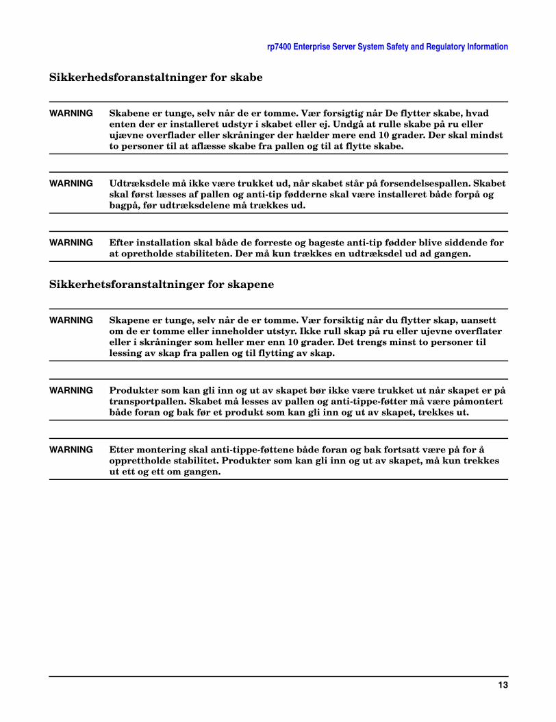
Sikkerhedsforanstaltninger for skabe
WARNING Skabene er tunge, selv når de er tomme. Vær forsigtig når De flytter skabe, hvad enten der er installeret udstyr i skabet eller ej. Undgå at rulle skabe på ru eller ujævne overflader eller skråninger der hælder mere end 10 grader. Der skal mindst to personer til at aflæsse skabe fra pallen og til at flytte skabe.
WARNING Udtræksdele må ikke være trukket ud, når skabet står på forsendelsespallen. Skabet skal først læsses af pallen og anti-tip fødderne skal være installeret både forpå og bagpå, før udtræksdelene må trækkes ud.
WARNING Efter installation skal både de forreste og bageste anti-tip fødder blive siddende for at opretholde stabiliteten. Der må kun trækkes en udtræksdel ud ad gangen.
Sikkerhetsforanstaltninger for skapene
WARNING Skapene er tunge, selv når de er tomme. Vær forsiktig når du flytter skap, uansett om de er tomme eller inneholder utstyr. Ikke rull skap på ru eller ujevne overflater eller i skråninger som heller mer enn 10 grader. Det trengs minst to personer til lessing av skap fra pallen og til flytting av skap.
WARNING Produkter som kan gli inn og ut av skapet bør ikke være trukket ut når skapet er på transportpallen. Skabet må lesses av pallen og anti-tippe-føtter må være påmontert både foran og bak før et produkt som kan gli inn og ut av skapet, trekkes ut.
WARNING Etter montering skal anti-tippe-føttene både foran og bak fortsatt være på for å opprettholde stabilitet. Produkter som kan gli inn og ut av skapet, må kun trekkes ut ett og ett om gangen.
13
rp7400 Enterprise Server System Safety and Regulatory Information
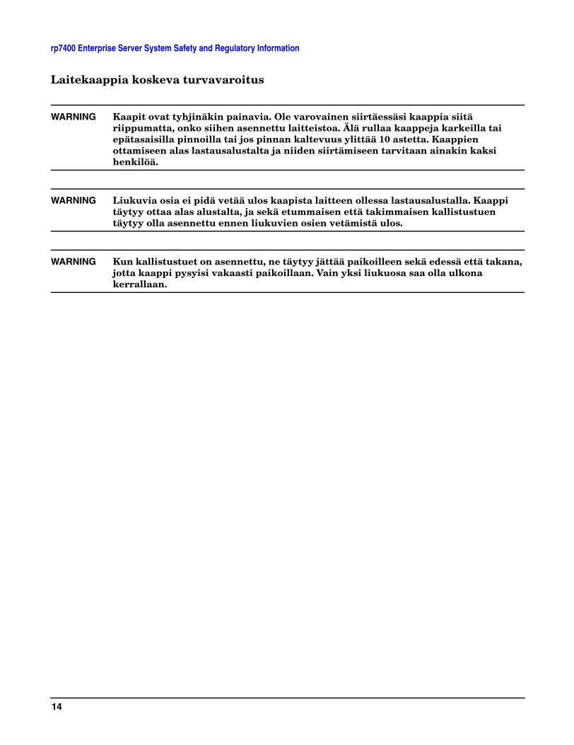
Laitekaappia koskeva turvavaroitus
WARNING Kaapit ovat tyhjinäkin painavia. Ole varovainen siirtäessäsi kaappia siitä riippumatta, onko siihen asennettu laitteistoa. Älä rullaa kaappeja karkeilla tai epätasaisilla pinnoilla tai jos pinnan kaltevuus ylittää 10 astetta. Kaappien ottamiseen alas lastausalustalta ja niiden siirtämiseen tarvitaan ainakin kaksi henkilöä.
WARNING Liukuvia osia ei pidä vetää ulos kaapista laitteen ollessa lastausalustalla. Kaappi täytyy ottaa alas alustalta, ja sekä etummaisen että takimmaisen kallistustuen täytyy olla asennettu ennen liukuvien osien vetämistä ulos.
WARNING Kun kallistustuet on asennettu, ne täytyy jättää paikoilleen sekä edessä että takana, jotta kaappi pysyisi vakaasti paikoillaan. Vain yksi liukuosa saa olla ulkona kerrallaan.
14

rp7400 Enterprise Server System Safety and Regulatory Information
15
rp7400 Enterprise Server System Safety and Regulatory Information
16

rp7400 Enterprise Server System Safety and Regulatory Information
17
rp7400 Enterprise Server System Safety and Regulatory Information
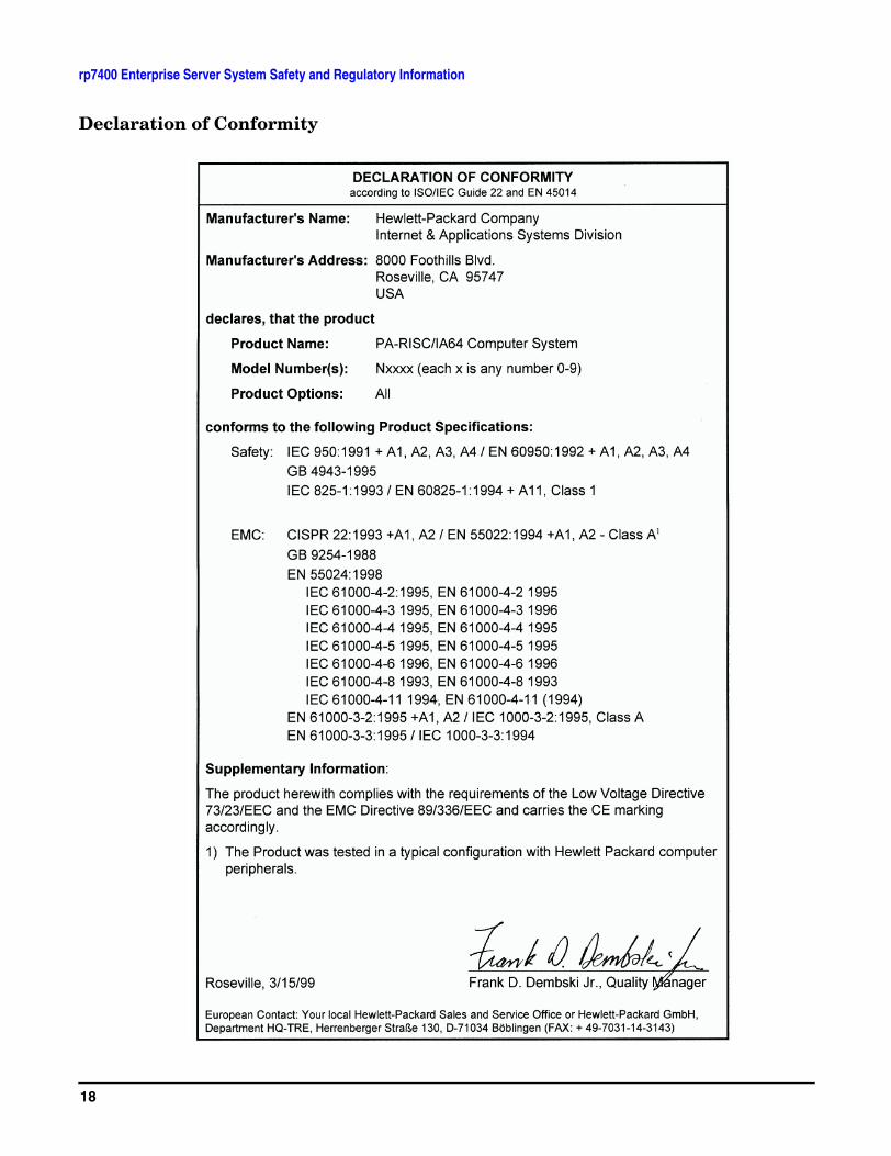
Declaration of Conformity
18
rp7400 Enterprise Server System Safety and Regulatory Information
FCC Statement (USA Only)
The United States Federal Communications Commission has specified that the following notice be brought to the attention of users of this product:
NOTE This equipment has been tested and found to comply with the limits for a Class A digital device, pursuant to part 15 of the FCC rules. These limits are designed to provide reasonable protection against harmful interference when the equipment is operated in a commercial environment. This equipment generates, uses, and can radiate radio frequency energy and, if not installed and used in accordance with the instruction manual, may cause harmful interference to radio communications. Operation of this equipment in a residential area is likely to cause harmful interference in which case the user will be required to correct the interference at his own expense.
Hewlett-Packard's system verification tests were conducted with HP-supported peripheral devices and HP shielded cables, such as those you receive with your computer. Changes or modifications not expressly approved by Hewlett-Packard could void the user's authority to operate the equipment. Cables used with this device must be properly shielded to comply with the requirements of the FCC.
Canada RFI Statement
This Class A digital apparatus meets all requirements of the Canadian Interference-Causing Equipment Regulations.
Notice relative aux interférences radioélectriques (Canada)
Cet appareil numérique de la classe A respecte toutes les exigences du Règlement sur le matériel brouilleur du Canada.
European Union RFI Statement
This is a Class A product. In a domestic environment, this product may cause radio interference in which case the user may be required to take adequate measures.
19
rp7400 Enterprise Server System Safety and Regulatory Information
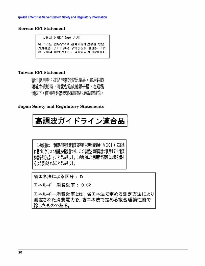
Korean RFI Statement
Taiwan RFI Statement
Japan Safety and Regulatory Statements
20
rp7400 Enterprise Server System Safety and Regulatory Information
Acoustics (Germany)
Acoustic noise level per ISO 9296 (25° C):
LpAm <60dB (operators position)
Geräuschemission (Deuschland)
Geräuschemission nach ISO 9296 (25° C):
LpAm <60dB (Arbeitsplatz)
Australian C-Tick Label
Laser Safety
This product contains a laser internal to the Optical Link Module (OLM) for connection to the Fibre communications port.
In the USA, the OLM is certified as a Class 1 laser product conforming to the requirements contained in the Department of Health and Human Services (DHHS) regulation 21 CFR, Subchapter J. The certification is indicated by a label on the plastic OLM housing.
Outside the USA, the OLM is certified as a Class 1 laser product conforming to the requirements contained in IEC 825-1:1993 and EN 60825-1:1994, including Amendment 11:1996.
21

rp7400 Enterprise Server System Safety and Regulatory Information
22
Review the Sales Order
Review the Sales OrderCustomer sales order information is available through the Support Connect system and through the WWOMS (World-Wide Order Management System). Carefully review the sales order information to assess:
• the number of integrated systems ordered
• the number of peripheral cabinets ordered
• the number and type of PDUs
• special configuration requirements
• delivery dates
23

Review the Sales Order
24
Plan the Site Visit
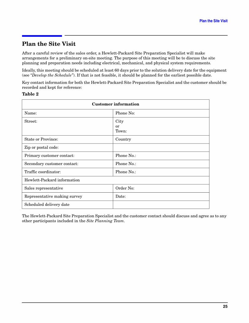
Plan the Site VisitAfter a careful review of the sales order, a Hewlett-Packard Site Preparation Specialist will make arrangements for a preliminary on-site meeting. The purpose of this meeting will be to discuss the site planning and preparation needs including electrical, mechanical, and physical system requirements.
Ideally, this meeting should be scheduled at least 60 days prior to the solution delivery date for the equipment (see “Develop the Schedule”). If that is not feasible, it should be planned for the earliest possible date.
Key contact information for both the Hewlett-Packard Site Preparation Specialist and the customer should be recorded and kept for reference:
The Hewlett-Packard Site Preparation Specialist and the customer contact should discuss and agree as to any other participants included in the Site Planning Team.
Table 2
Customer information
Name: Phone No:
Street: CityorTown:
State or Province: Country
Zip or postal code:
Primary customer contact: Phone No.:
Secondary customer contact: Phone No.:
Traffic coordinator: Phone No.:
Hewlett-Packard information
Sales representative Order No:
Representative making survey Date:
Scheduled delivery date
25

Plan the Site Visit
26

Visit the Site
Visit the SiteDuring the preliminary site visit, it is important that the Hewlett-Packard Site Preparation Specialist and the customer representative accomplish the following major tasks:
27

Visit the Site
28

Review Customer Responsibilities
Review Customer ResponsibilitiesThe customer is responsible for scheduling, planning, and preparing a suitable environment for the installation and operation of a complete computer system. The Hewlett-Packard Site Preparation Specialist will be available to assist you throughout the planning and preparation for and the installation of your system. Carefully read the Site Planning and Warranty Information provided with your system.
The HP rp7400 Enterprise Servers are primarily designed to be installed and operated in computer room environments. DO NOT INSTALL HP rp7400 ENTERPRISE SERVERS IN AN OFFICE ENVIRONMENT. The power, airflow, and acoustic characteristics of rp7400 servers make it unsuitable for operation in office environments.
If computers are new to your site, you will need to pay particular attention to the following items:
• Airflow
• Local building codes
• Local electrical codes
• Local safety codes
• Space and weight limitations/system accessibility
• Environmental requirements (temperature, humidity, etc.)
• Electrical and grounding requirements
• Acoustics
If your computer is to be installed in an existing computer room, you should analyze the following items and integrate them into your site plan:
• Available space
• Environmental requirements
• Electrical requirements
• Airflow
• Acoustics
Local Codes
Special local codes exist in some locations regulating the installation of computer equipment. The customer is responsible for making sure their computer system installation is in compliance with all local laws, regulations, and codes for mechanical, building, and electrical distribution systems prior to system installation. The Hewlett-Packard Site Preparation Specialist can assist you in determining your local regulations.
Data Communications Equipment
The customer is responsible for ordering and installing all required data communications equipment such as:
• Any hardware or cables for connection or installation of data communications equipment
• Network Links
• Telephone equipment
29
Review Customer Responsibilities
• Modems (Consult with the Site Preparation Specialist for Hewlett-Packard requirements.)
• Equipment supplied by companies other than HP
Communications equipment at the computer site is not part of the computer and must be considered separately for power, space, interface cables, and cooling requirements.
Selection of Site Personnel
Depending on the complexity of the computer system, the customer is responsible for selecting a Site Coordinator, Principal Operator, and a Site Planning Team. Depending on customer requirements, the Principal Operator may or may not perform all of these tasks. In some installations there may be two or three people assigned to the various “operator” responsibilities.
Site Coordinator
The Site Coordinator is responsible for the following tasks:
• Establishing and maintaining site preparation schedules
• Coordinating construction efforts
• Primary liaison with Hewlett-Packard representatives
Principal Operator
The Principal Operator is responsible for the following tasks:
• System operation
• Monitoring site preparation
• Ordering computer supplies
• Scheduling user training
• Maintaining maintenance schedules
Site Planning Team
The Site Planning Team is responsible for the following tasks:
• Determining site location and size
• Reviewing construction requirements
• Reviewing local codes
• Reviewing insurance requirements
• Scheduling all events related to site completion
Members of the Site Planning Team should include the Site Coordinator, Principal Operator, and the Hewlett-Packard Site Preparation Specialist. When possible, the electrical contractor, a site construction coordinator (familiar with local electrical codes), and an air conditioning specialist should be included.
30
Review HP Responsibilities
Review HP ResponsibilitiesThe following paragraphs outline Hewlett-Packard’s site planning and verification services.
Site Planning Visit
Upon receipt of a purchase order, a Hewlett-Packard Site Preparation Specialist will make arrangements for an on-site meeting with your principal operator and electrician. As a part of this on-site meeting, the Site Preparation Specialist will discuss site planning and preparation needs including electrical, mechanical, and physical system requirements. If required, a Hewlett-Packard Site Preparation Specialist will be available for consultation.
As a result of this visit, a site layout plan agreeable to you and Hewlett-Packard will be created.
Site Verification Visit
A Hewlett-Packard Site Preparation Specialist will verify that your site meets or exceeds your computer system’s requirements and specifications prior to and during system installation. Sites failing to meet the system requirements and specifications may incur additional service charges.
Hewlett-Packard provides service under the conditions of the Computer Products Warranty & Installation Terms, Customer Support Services Agreement, Installation Support Plan, and on a time and materials basis.
Third Party Service
If an HP rp7400 Enterprise Server and/or applications software is purchased from a “third party vendor”, that third party is responsible for providing consultation services on the system operation and applications software.
In the situation of a third party purchase, a maintenance agreement for hardware and an Account Management Service (AMS) for software are available directly from Hewlett-Packard.
31

Review HP Responsibilities
32

Verify system complicity with regulatory standards
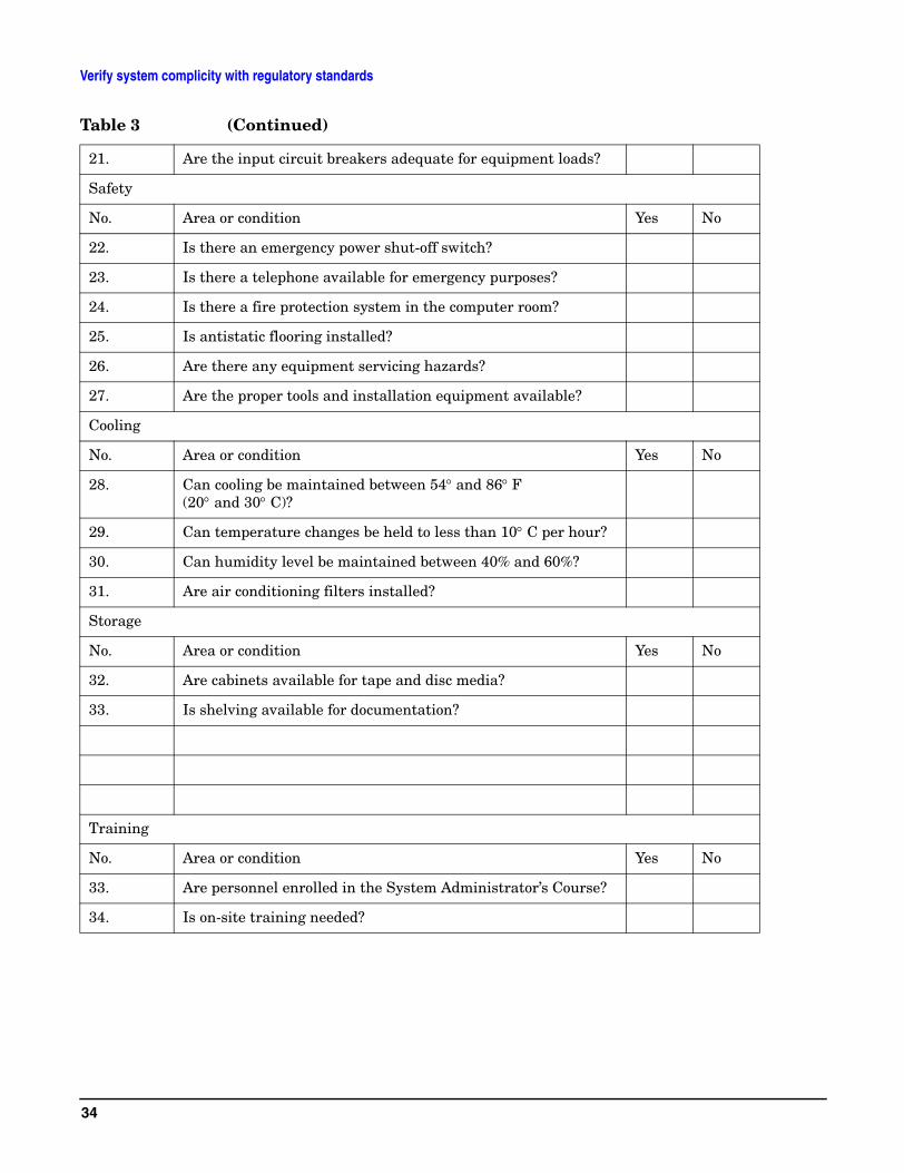
Verify system complicity with regulatory standardsThe following checklist should be filled out during the preliminary site visit to ensure regulatory standards are met and that any site deficiencies are identified:
Table 3
Computer room
No. Area or condition Yes No
1. Is there a copy of the completed floor plan?
2. Is there adequate space for maintenance needs?
3. Is access to the site or computer room restricted?
4. Is the computer room structurally complete?
5. Is a raised floor installed?
6. Is the raised floor adequate for equipment loading?
7. Are there channels or cutouts for cable routing?
8. Is there a remote console telephone line available with an RJ11 jack?
9. Are telephone lines for remote support available?
10. Are customer supplied peripheral cables available?
12. Is a lift tool available if required?
Power and lighting
No. Area or condition Yes No
13. Are lighting levels adequate for maintenance?
14. Are there ac outlets available for servicing needs?
15. Does the input voltage correspond to equipment specifications?
16 Does the input frequency correspond to equipment specifications?
17. Are lightning arrestors installed?
18. Is power conditioning equipment installed?
No. Area or condition Yes No
19. Is there a dedicated branch circuit for equipment?
20. Is the dedicated branch circuit less than 250 feet (72.5 meters)?
33
Verify system complicity with regulatory standards
21. Are the input circuit breakers adequate for equipment loads?
Safety
No. Area or condition Yes No
22. Is there an emergency power shut-off switch?
23. Is there a telephone available for emergency purposes?
24. Is there a fire protection system in the computer room?
25. Is antistatic flooring installed?
26. Are there any equipment servicing hazards?
27. Are the proper tools and installation equipment available?
Cooling
No. Area or condition Yes No
28. Can cooling be maintained between 54° and 86° F (20° and 30° C)?
29. Can temperature changes be held to less than 10° C per hour?
30. Can humidity level be maintained between 40% and 60%?
31. Are air conditioning filters installed?
Storage
No. Area or condition Yes No
32. Are cabinets available for tape and disc media?
33. Is shelving available for documentation?
Training
No. Area or condition Yes No
33. Are personnel enrolled in the System Administrator’s Course?
34. Is on-site training needed?
Table 3 (Continued)
34
Develop the Schedule
Develop the ScheduleThe following schedule lists the sequence of events for an ideal system installation.
• 60 days before installation
— Floor plan design completed and mailed to Hewlett-Packard
• 30 days before installation
— Primary power and air conditioning installation completed
— Telephone and data cables installed
— Fire protection equipment installed
— Major facility changes completed
— Special delivery requirements defined
— Site inspection survey completed
— Delivery survey completed
— Signed copy of the site inspection and delivery survey mailed to Hewlett-Packard
— Site inspection and predelivery coordination meeting arranged with a Hewlett-Packard Site Preparation Specialist to review the inspection checklist and arrange a solution delivery schedule.
• Solution delivery date
— Final check made with an Hewlett-Packard Site Preparation Specialist to resolve any last minute problems
35

Develop the Schedule
36
Specify the Space for Unpacking
Specify the Space for Unpacking
Specify Uncrating Space
rp7400 Systems are shipped in integrated cabinets on a 40in. x 48in. pallet. The combined height of the packaged container and the pallets are as follows:
• 1.1 meter rack - 60in.
• 1.6 meter rack - 73in.
• 2.0 meter rack - 87in.
Allow a circular area approximately 12ft. in diameter room for uncrating the system and rolling the cabinet off the pallet on rails. Allow additional space for temporary storage of the shipping containers and packing materials.
Specify the Aisle Space
There should be enough clearance to move equipment safely from the receiving area to the computer room. Permanent obstructions, such as pillars or narrow doorways, can cause equipment damage. Allow a minimum of 2ft. clearance on either side of the cabinet or shipping container to allow for maneuvering the equipment.
Delivery plans should include the possible removal of walls or doors.
37

Specify the Space for Unpacking
38
Specify Raised Floor Requirements
Specify Raised Floor RequirementsIf a raised floor system is used, a complete grounding grid for maintaining equal potential over a broad band of frequencies should be installed. The grounding grid should be connected to the equipment cabinet and electrical service entrance ground at multiple connection points via minimum #6 AWG (16mm2) wire ground connector.
There are three types of raised floor systems:
• Free standing - consists solely of the tiles and pedestals supporting the tiles. Metal backing on the tiles supports the weight from one pedestal to the next, and provides electrical continuity from one pedestal to the next.
• Drop-in stringers - a simple metal bar extends from one pedestal to another, providing additional support for the tile. Weight distribution and electrical continuity are improved over the free standing system.
• Bolt-in stringer - a metal bar extends from one pedestal to the next, but the bar is bolted into place, providing additional electrical and mechanical security. The system provides the best electrical continuity and weight distribution.
Bolt-in String System grounding: One approach to grounding for bolt-in stringer systems go around the entire perimeter of the room, connecting every third pedestal with #4 AWG or #6 AWG wire. Then make an ‘X’ through the center part of the room with the wire. If the room is very large or irregularly shaped, several ‘X’s may be required, all connected to the same perimeter ground.
Drop-in Stringer system grounding. Use the ‘X’ system described for drop-in stringer systems.
Free-standing system grounding:
• Excellent — Add a grounding strip to the subfloor. The grounding grid should be made of aluminum strips mounted to the subfloor. The strips should be 0.032 in. (0.08 cm) thick and a minimum of 3.0 in. (8.0 cm) wide.
39
Specify Raised Floor Requirements
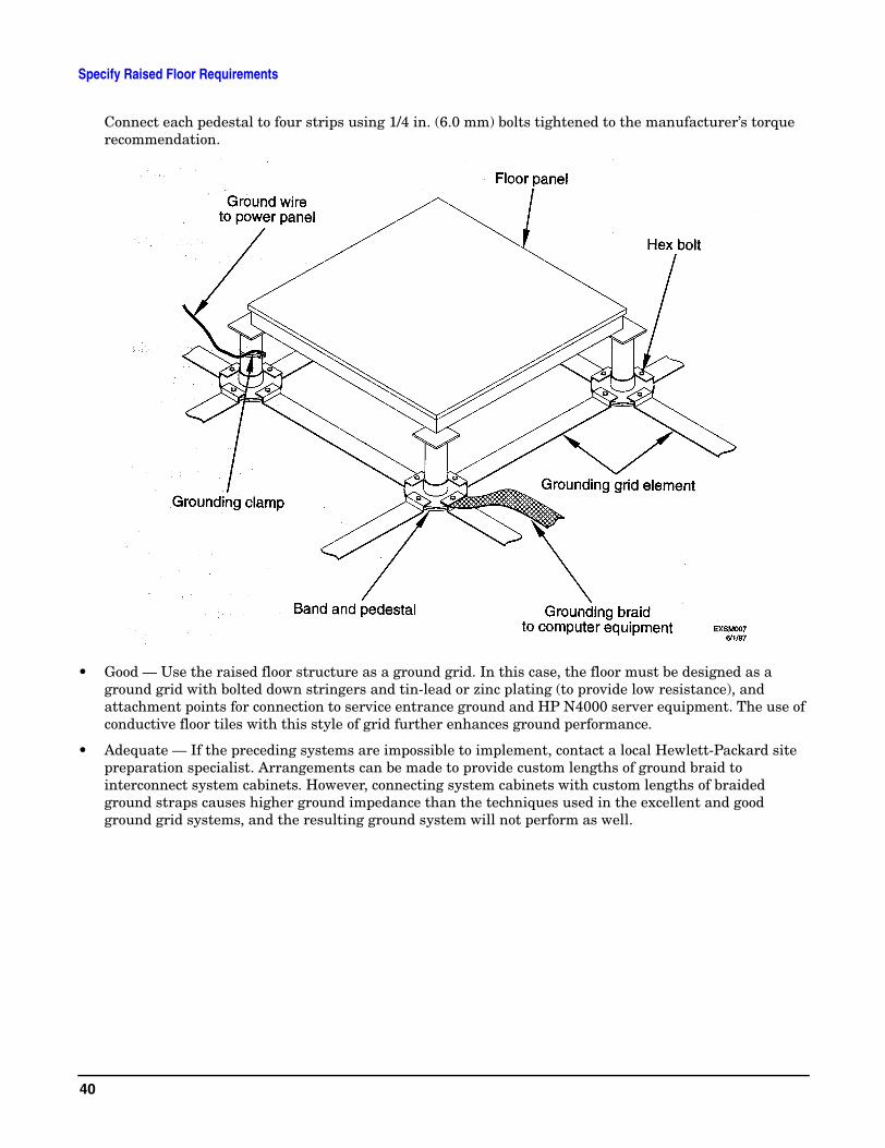
Connect each pedestal to four strips using 1/4 in. (6.0 mm) bolts tightened to the manufacturer’s torque recommendation.
• Good — Use the raised floor structure as a ground grid. In this case, the floor must be designed as a ground grid with bolted down stringers and tin-lead or zinc plating (to provide low resistance), and attachment points for connection to service entrance ground and HP N4000 server equipment. The use of conductive floor tiles with this style of grid further enhances ground performance.
• Adequate — If the preceding systems are impossible to implement, contact a local Hewlett-Packard site preparation specialist. Arrangements can be made to provide custom lengths of ground braid to interconnect system cabinets. However, connecting system cabinets with custom lengths of braided ground straps causes higher ground impedance than the techniques used in the excellent and good ground grid systems, and the resulting ground system will not perform as well.
40
Specify Raised Floor Requirements
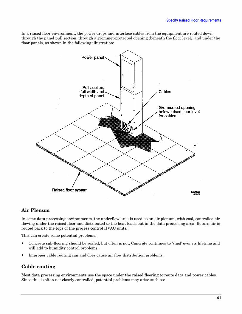
In a raised floor environment, the power drops and interface cables from the equipment are routed down through the panel pull section, through a grommet-protected opening (beneath the floor level), and under the floor panels, as shown in the following illustration:
Air Plenum
In some data processing environments, the underflow area is used as an air plenum, with cool, controlled air flowing under the raised floor and distributed to the heat loads out in the data processing area. Return air is routed back to the tops of the process control HVAC units.
This can create some potential problems:
• Concrete sub-flooring should be sealed, but often is not. Concrete continues to ‘shed’ over its lifetime and will add to humidity control problems.
• Improper cable routing can and does cause air flow distribution problems.
Cable routing
Most data processing environments use the space under the raised flooring to route data and power cables. Since this is often not closely controlled, potential problems may arise such as:
41
Specify Raised Floor Requirements
• Air flow impedance and misrouting
• Electromagnetic interference from parallel runs in close proximity to one another
• Liquid spills beneath the floor may go unnoticed for long periods.
• Where cable breaches raised floor, abrasion may cause severe shock hazards.
In general, cables should be routed parallel to the air flow, and not horizontal to it. Additionally, extreme care should be given to ensure that data and power cables are not routed close together in a parallel fashion. In fact, these cables should be separated by a minimum of 6 inches wherever physically possible.
Safety Hazards
Most electrical codes dictate that if an electrical shock hazard exists, some method to curb this must be used. For instance, “any non-current carrying metallic part of a structure that could be energized and touched by personnel has to be grounded.” With all of the power and data cables routed beneath the flooring and pulled up into the data are, the chances for short exist. As the tiles are metallic clad, it is conceivable that the shock hazard may exist. For this reason, it is critical that a raised floor be properly grounded.
Performance Drain
A raised floor acts as a voltage divider -- a capacitive plate -- and it may create a performance issue for computer systems if improperly grounded. Computer systems create both electrostatic discharge and electromagnetic interference, and as processor speeds increase, these effects increase as well. If the flooring system is properly grounded, the metallic grids will act to dissipate the buildup of ESD and EMI.
42
Specify Hard Floor Requirements
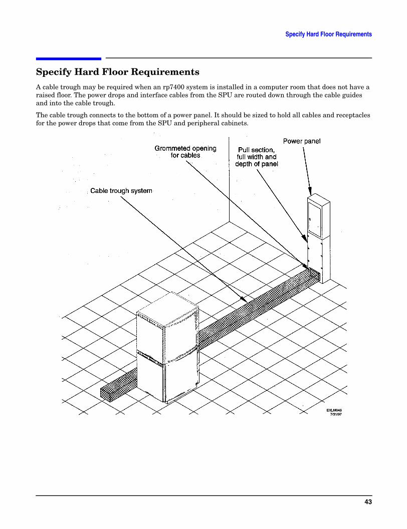
Specify Hard Floor RequirementsA cable trough may be required when an rp7400 system is installed in a computer room that does not have a raised floor. The power drops and interface cables from the SPU are routed down through the cable guides and into the cable trough.
The cable trough connects to the bottom of a power panel. It should be sized to hold all cables and receptacles for the power drops that come from the SPU and peripheral cabinets.
43

Specify Hard Floor Requirements
44
Specify Power Connections
Specify Power ConnectionsThe HP rp7400 power system is a 200/208/230/240 VAC product requiring a dedicated 20A branch circuit. The power system is comprised of two or three 10A, 1163W n+1 hot-swappable system power supplies, depending on how the system is configured. The total continuously available power to the SPU is 2 x 1163W or 2325W.
HP does not support plugging HP rp7400 power supplies into wall or floor sockets. The power cords provided for the power supply is plugged directly into a UPS or a power distribution unit (PDU) using a jumper cord (HP part number 8120-1860). Customers wishing to connect directly to wall or floor sockets must provide their own power cord solution.
NOTE The acronym PDU (power distribution unit) in this document refers to the power strips attached to the HP rp7400 cabinet.
CAUTION HP does not recommend and does not support the use of “ferro-active” or “ferro-resonant” power correction in conjunction with the rp7400 server. These type of line conditioners represent an older technology that is not compatible with the most recent designs in active PFC power supplies such as those in the HP rp7400 servers. “Ferro-active” or “ferro-resonant” line conditioners may cause an increase in total harmonic distortion and may produce significant and unpredictable voltage regulation anomalies.
Modular PDUs
Two modular PDUs are available for use with the rp7400 product:
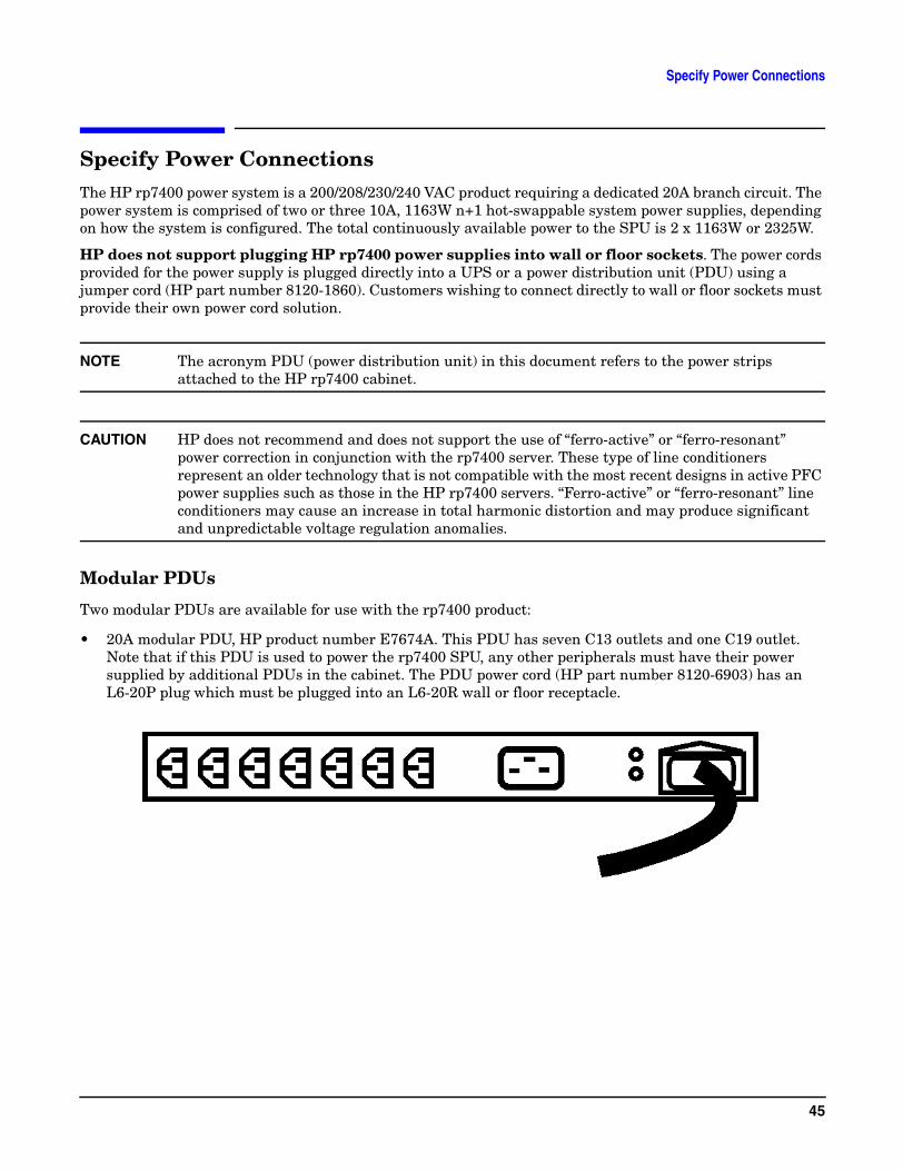
• 20A modular PDU, HP product number E7674A. This PDU has seven C13 outlets and one C19 outlet. Note that if this PDU is used to power the rp7400 SPU, any other peripherals must have their power supplied by additional PDUs in the cabinet. The PDU power cord (HP part number 8120-6903) has an L6-20P plug which must be plugged into an L6-20R wall or floor receptacle.
45
Specify Power Connections
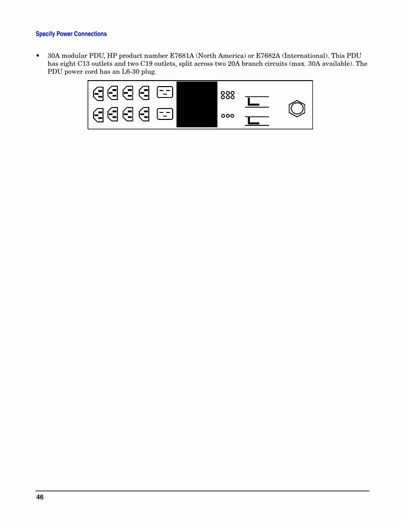
• 30A modular PDU, HP product number E7681A (North America) or E7682A (International). This PDU has eight C13 outlets and two C19 outlets, split across two 20A branch circuits (max. 30A available). The PDU power cord has an L6-30 plug.
46
Specify Grounding Requirements
Specify Grounding Requirements
Grounding systems
HP rp7400 servers require two methods of grounding:
• Power distribution safety grounding
• High frequency intercabinet grounding
NOTE Some of the grounding requirements described here may differ outside of North America.
Power distribution safety grounding
The power distribution safety grounding system consists of connecting various points in the power distribution system to earth ground using green (green/yellow) wire ground conductors. Having these ground connections tied to metal chassis parts that may be touched by computer room personnel protects them against shock hazard from current leakage and fault conditions.
Power distribution systems consist of several parts. Hewlett-Packard recommends that these parts be solidly interconnected to provide an equal-potential ground to all points.
Main building electrical ground The main electrical service entrance equipment should have an earth ground connection, as required by applicable codes. Connections such as a grounding rod, building steel, or a conductive type cold water service pipe provide an earth ground.
Electrical conduit ground All electrical conduits should be made of rigid metallic conduit, Flex-T conduit, or liquid-tight conduit that is securely connected together or bonded to panels and electrical boxes, so as to provide a continuous grounding system.
Power panel ground Each power panel should be grounded to the electrical service entrance with green (green/yellow) wire ground conductors. The green (green/yellow) wire ground conductors should be sized per applicable codes (based on circuit over current device ratings).
Computer equipment ground Ground all computer equipment with the green (green/yellow) wire included in the branch circuitry. The green (green/yellow) wire ground conductors should be connected to the appropriate power panel and should be parity-sized (based on circuit over current device ratings).
Cabinet interconnect grounding
Signal interconnect between system cabinets requires high frequency ground return paths. Connect all cabinets to site ground.
NOTE In some cases power distribution system green (green/yellow) wire ground conductors are too long and inductive to provide adequate high frequency ground return paths. Therefore, the customer may choose to provide a ground strap for connecting the system cabinet to the site grounding grid (customer-supplied). Installation of this ground strap is optional and there is a chance that it may cause ground loops.
Power panels located in close proximity to the computer equipment should also be connected to site grounding grid. Methods of providing a sufficiently high frequency ground grid are described in the next sections.
47
Specify Grounding Requirements
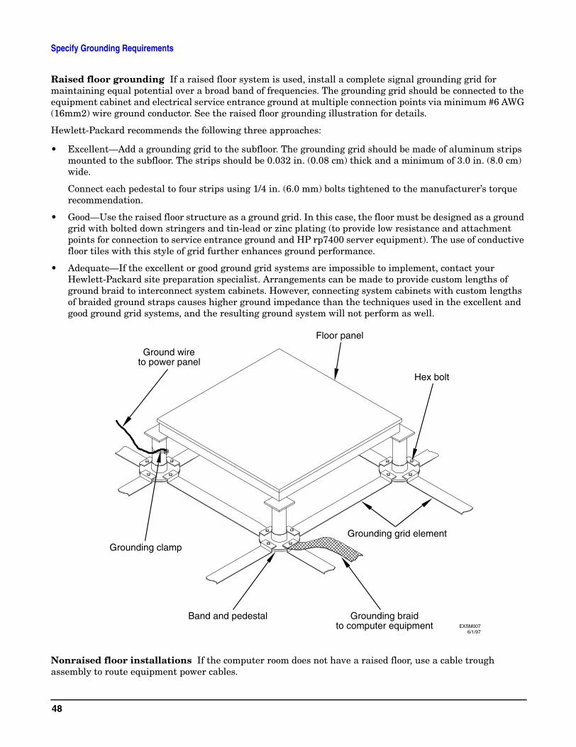
Raised floor grounding If a raised floor system is used, install a complete signal grounding grid for maintaining equal potential over a broad band of frequencies. The grounding grid should be connected to the equipment cabinet and electrical service entrance ground at multiple connection points via minimum #6 AWG (16mm2) wire ground conductor. See the raised floor grounding illustration for details.
Hewlett-Packard recommends the following three approaches:
• Excellent—Add a grounding grid to the subfloor. The grounding grid should be made of aluminum strips mounted to the subfloor. The strips should be 0.032 in. (0.08 cm) thick and a minimum of 3.0 in. (8.0 cm) wide.
Connect each pedestal to four strips using 1/4 in. (6.0 mm) bolts tightened to the manufacturer’s torque recommendation.
• Good—Use the raised floor structure as a ground grid. In this case, the floor must be designed as a ground grid with bolted down stringers and tin-lead or zinc plating (to provide low resistance and attachment points for connection to service entrance ground and HP rp7400 server equipment). The use of conductive floor tiles with this style of grid further enhances ground performance.
• Adequate—If the excellent or good ground grid systems are impossible to implement, contact your Hewlett-Packard site preparation specialist. Arrangements can be made to provide custom lengths of ground braid to interconnect system cabinets. However, connecting system cabinets with custom lengths of braided ground straps causes higher ground impedance than the techniques used in the excellent and good ground grid systems, and the resulting ground system will not perform as well.
Nonraised floor installations If the computer room does not have a raised floor, use a cable trough assembly to route equipment power cables.
Ground wireto power panel
Grounding clamp
Band and pedestal Grounding braidto computer equipment
Grounding grid element
Hex bolt
Floor panel
6/1/97EXSM007
48
Specify Grounding Requirements
This cable trough assembly may be used as the conduit for high frequency ground. In addition to possible ground connections to Hewlett-Packard cabinets, the cable trough should be connected to the electrical service ground at multiple connection points via a minimum #6 AWG (16mm2) wire ground conductor. See the figure following for details.
Equipment grounding implementation details
If it has been determined to be necessary, connect all Hewlett-Packard equipment cabinets to the site ground grid as follows:
• Attach one end of each ground strap to the applicable cabinet ground lug.
• Attach the other end to the nearest pedestal base (raised floor) or cable trough ground point (nonraised floor).
• Check that the braid contact on each end of the ground strap consists of a terminal and connection hardware (a 1/4-in. (6.0-mm) bolt, nuts, and washers).
49

Specify Grounding Requirements
• Check that the braid contact connection points are free of paint or other insulating material and treated with a contact enhancement compound (similar to Burndy Penetrox).
Cable trough top
Ground connection ofpanel ground wire
(inside trough)
Hex bolt,bellville washer and nut
Open end at panelHex bolt,
bellville washer and nutGrounding braid to
computer equipment
Drill troughas required
Cable trough
Ground wire
Cable trough top andcable trough is usedas grounding system
6/1/97EXSM008
50
Specify the System Requirements
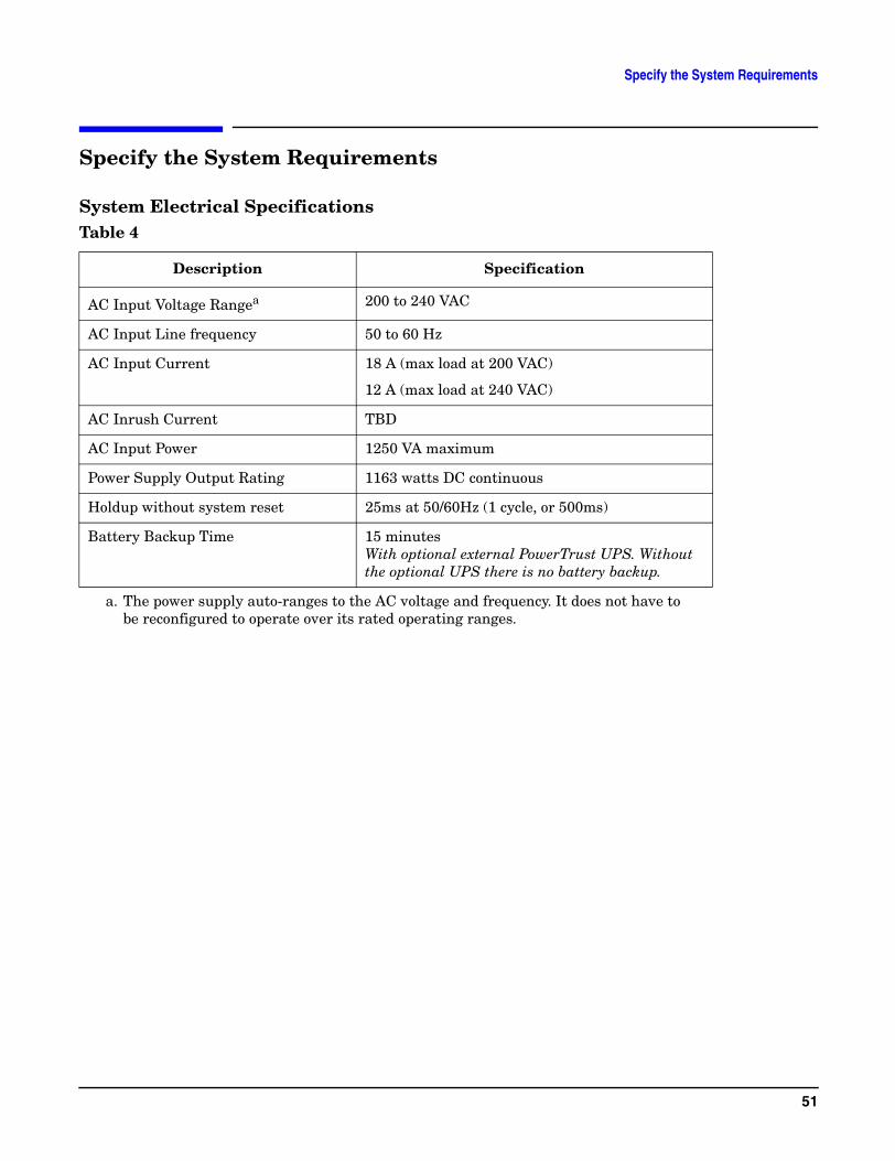
Specify the System Requirements
System Electrical SpecificationsTable 4
Description Specification
AC Input Voltage Rangea
a. The power supply auto-ranges to the AC voltage and frequency. It does not have to be reconfigured to operate over its rated operating ranges.
200 to 240 VAC
AC Input Line frequency 50 to 60 Hz
AC Input Current 18 A (max load at 200 VAC)
12 A (max load at 240 VAC)
AC Inrush Current TBD
AC Input Power 1250 VA maximum
Power Supply Output Rating 1163 watts DC continuous
Holdup without system reset 25ms at 50/60Hz (1 cycle, or 500ms)
Battery Backup Time 15 minutesWith optional external PowerTrust UPS. Without the optional UPS there is no battery backup.
51

Specify the System Requirements
52
Identify the High Availability Requirements
Identify the High Availability Requirements
SPU-level Enhanced Power Availability
At the SPU level, enhanced power availability is achieved through the n+1 hot-swappable power supplies.
Two power supplies are required for normal rp7400 system operation and in order to allow the system to boot. The third power supply is a redundant power supply that provides the n+1 capability.
Any one of the power supplies can fail without affecting system performance, and can be replaced while the system is on-line. Single point of failure is reduced to the PDU or PowerTrust UPS to which the power supply power cords are connected.
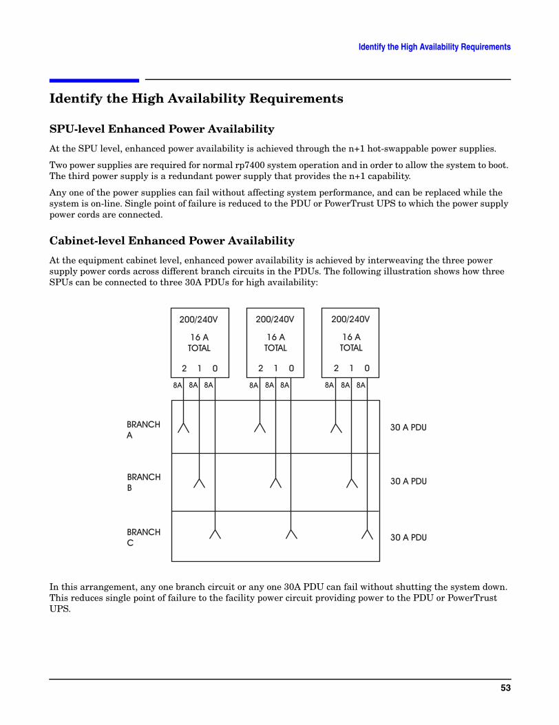
Cabinet-level Enhanced Power Availability
At the equipment cabinet level, enhanced power availability is achieved by interweaving the three power supply power cords across different branch circuits in the PDUs. The following illustration shows how three SPUs can be connected to three 30A PDUs for high availability:
In this arrangement, any one branch circuit or any one 30A PDU can fail without shutting the system down. This reduces single point of failure to the facility power circuit providing power to the PDU or PowerTrust UPS.
53

Identify the High Availability Requirements
Site-level Power High Availability
Some customer sites with critical applications may require high availability power beyond the scope of the equipment provided by Hewlett-Packard. Computer room high-availability can be achieved by:
• multiple substation power feeds off a single power substation
• feeds from multiple power substations
Such implementations are costly and complex, but have the advantage of eliminating single point of failure to the equipment.
54
Determine the ESD Requirements
Determine the ESD RequirementsStatic charges (voltage levels) occur when objects are separated or rubbed together. The voltage level of a static charge is determined by the following factors:
• Types of materials
• Relative humidity
• Rate of change or separation
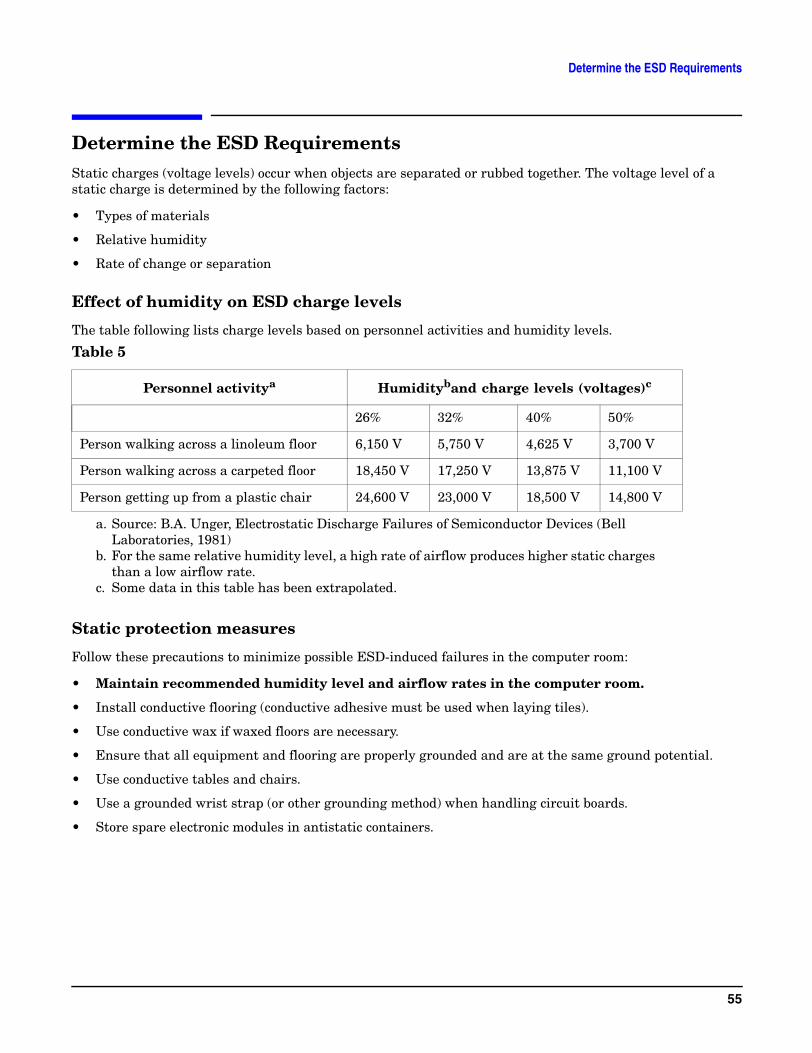
Effect of humidity on ESD charge levels
The table following lists charge levels based on personnel activities and humidity levels.
Static protection measures
Follow these precautions to minimize possible ESD-induced failures in the computer room:
• Maintain recommended humidity level and airflow rates in the computer room.
• Install conductive flooring (conductive adhesive must be used when laying tiles).
• Use conductive wax if waxed floors are necessary.
• Ensure that all equipment and flooring are properly grounded and are at the same ground potential.
• Use conductive tables and chairs.
• Use a grounded wrist strap (or other grounding method) when handling circuit boards.
• Store spare electronic modules in antistatic containers.
Table 5
Personnel activitya
a. Source: B.A. Unger, Electrostatic Discharge Failures of Semiconductor Devices (Bell Laboratories, 1981)
Humidityband charge levels (voltages)c
b. For the same relative humidity level, a high rate of airflow produces higher static charges than a low airflow rate.
c. Some data in this table has been extrapolated.
26% 32% 40% 50%
Person walking across a linoleum floor 6,150 V 5,750 V 4,625 V 3,700 V
Person walking across a carpeted floor 18,450 V 17,250 V 13,875 V 11,100 V
Person getting up from a plastic chair 24,600 V 23,000 V 18,500 V 14,800 V
55

Determine the ESD Requirements
56
Determine the Acoustic Requirements
Determine the Acoustic RequirementsThe acoustic specifications for rp7400 servers are as follows:
Reducing Acoustic Noise Levels
Ambient noise level in a computer room can be reduced by the following means:
• Dropped ceiling—Cover with a commercial grade of fire-resistant, acoustic rated, fiberglass ceiling tile.
• Sound deadening—Cover the walls with curtains or other sound deadening material.
• Removable partitions—Use foam rubber models for most effectiveness.
Sound power 7.5 Bels LwA maximum at >31oC
Sound pressure 61 dB maximum at > 31o C in operator position.58 dB maximum at >31o C in standby position.
No prominent tones
57

Determine the Acoustic Requirements
58
Determine RFI Requirements
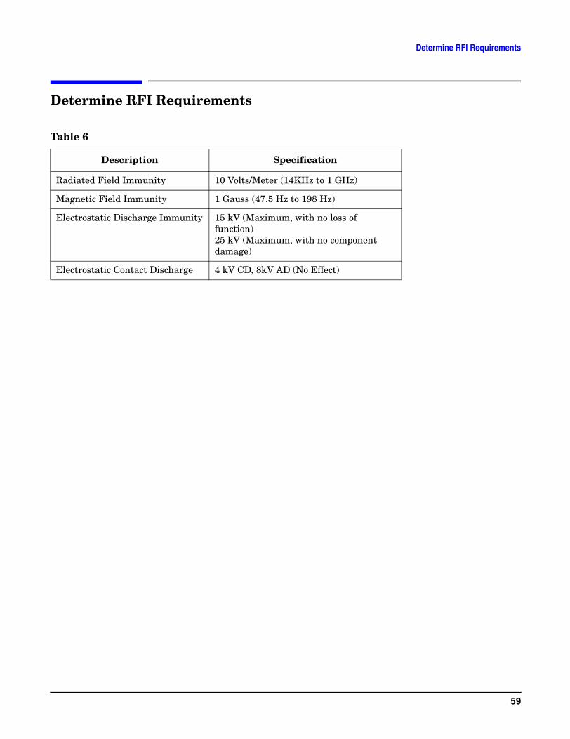
Determine RFI Requirements
Table 6
Description Specification
Radiated Field Immunity 10 Volts/Meter (14KHz to 1 GHz)
Magnetic Field Immunity 1 Gauss (47.5 Hz to 198 Hz)
Electrostatic Discharge Immunity 15 kV (Maximum, with no loss of function)25 kV (Maximum, with no component damage)
Electrostatic Contact Discharge 4 kV CD, 8kV AD (No Effect)
59

Determine RFI Requirements
60

Review Local Codes
Review Local CodesSpecial local codes exist in some locations regulating the installation of computer equipment. The customer is responsible for making sure their computer system installation is in compliance with all local laws, regulations, and codes for mechanical, building, and electrical distribution systems prior to system installation. The Hewlett-Packard Site Preparation Specialist can assist in determining your local regulations.
61

Review Local Codes
62
Determine Altitude Requirements
Determine Altitude Requirements
Effects of Altitude
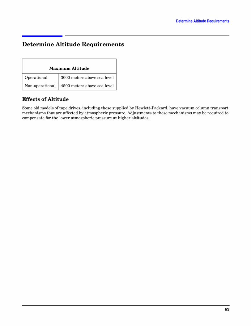
Some old models of tape drives, including those supplied by Hewlett-Packard, have vacuum column transport mechanisms that are affected by atmospheric pressure. Adjustments to these mechanisms may be required to compensate for the lower atmospheric pressure at higher altitudes.
Maximum Altitude
Operational 3000 meters above sea level
Non-operational 4500 meters above sea level
63

Determine Altitude Requirements
64
Determine Temperature/Humidity Requirements
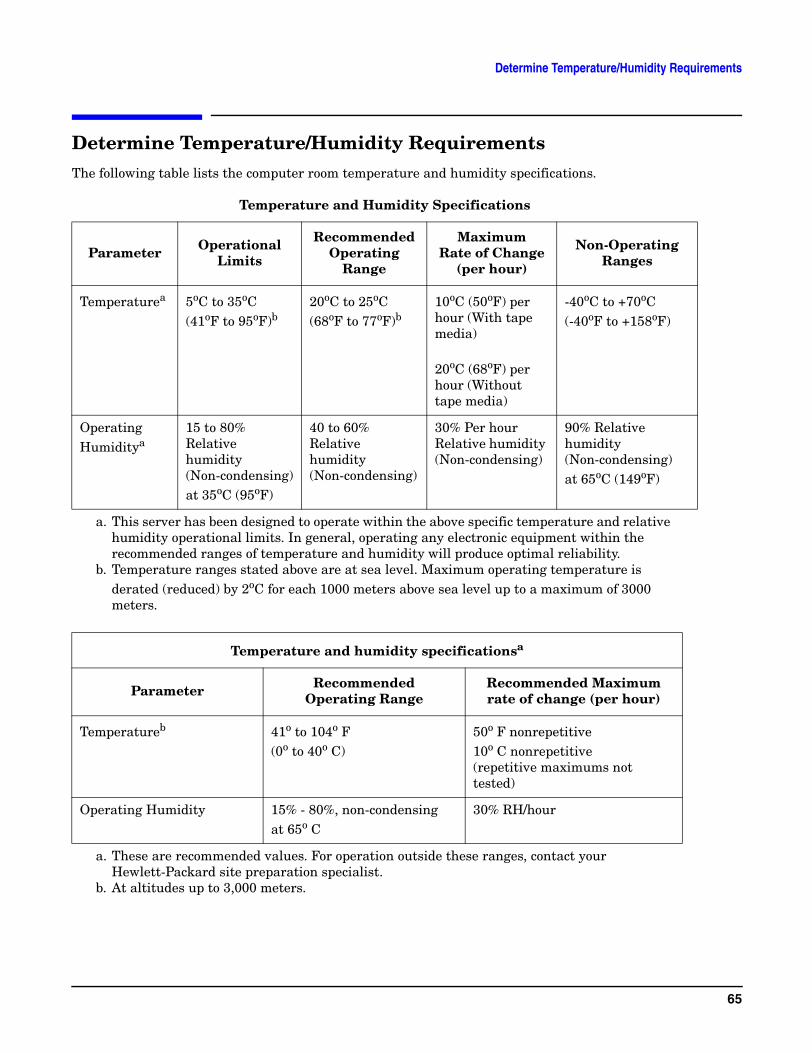
Determine Temperature/Humidity RequirementsThe following table lists the computer room temperature and humidity specifications.
Temperature and Humidity Specifications
Parameter Operational Limits
RecommendedOperating
Range
Maximum Rate of Change
(per hour)
Non-Operating Ranges
Temperaturea
a. This server has been designed to operate within the above specific temperature and relative humidity operational limits. In general, operating any electronic equipment within the recommended ranges of temperature and humidity will produce optimal reliability.
5oC to 35oC (41oF to 95oF)b
b. Temperature ranges stated above are at sea level. Maximum operating temperature is derated (reduced) by 2oC for each 1000 meters above sea level up to a maximum of 3000 meters.
20oC to 25oC(68oF to 77oF)b
10oC (50oF) per hour (With tape media)
20oC (68oF) per hour (Without tape media)
-40oC to +70oC(-40oF to +158oF)
Operating Humiditya
15 to 80% Relative humidity (Non-condensing) at 35oC (95oF)
40 to 60% Relative humidity (Non-condensing)
30% Per hour Relative humidity (Non-condensing)
90% Relative humidity (Non-condensing) at 65oC (149oF)
Temperature and humidity specificationsa
a. These are recommended values. For operation outside these ranges, contact your Hewlett-Packard site preparation specialist.
Parameter RecommendedOperating Range
Recommended Maximumrate of change (per hour)
Temperatureb
b. At altitudes up to 3,000 meters.
41o to 104o F(0o to 40o C)
50o F nonrepetitive10o C nonrepetitive(repetitive maximums not tested)
Operating Humidity 15% - 80%, non-condensingat 65o C
30% RH/hour
65

Determine Temperature/Humidity Requirements
NOTE Operating ranges refer to the ambient air temperature and humidity measured at the cabinet cooling air intake vents.
66
Identify Sources of Electrical Interference
Identify Sources of Electrical InterferenceThe following are some of the sources of electrical interference that may affect rp7400 servers.
Convenience Wall Outlets
Power outlets for building maintenance equipment (i.e., vacuum cleaners, floor buffers, etc.) must be wired from circuit breakers on a power panel separate from the computer system panel. The ground wires from these outlets must be connected to the normal building distribution panel; not the computer system ground.
If a separate power source and separate ground are not provided, operation of janitorial equipment can induce electrical noise and cause abnormal operation of the computer system. Your electrician can verify whether or not maintenance outlets are on separate panels.
Lightning
In some geographical areas it may by advisable to install lightning protection for both personnel and computer systems. In the United States (USA), the installation of lightning or surge arrestors on power and communication lines is described in the National Electrical Code, Article 280. All lightning arrestors must have the UL 1449 rating and should be tested to survive the suite of IEEE587 tests.
The principles of lightning protection and personnel safety are outlined in detail in the lightning protection code contained in the National Fire Protection Association (NFPA) Handbook.
67

Identify Sources of Electrical Interference
68
Identify Other Environmental Influences
Identify Other Environmental InfluencesThe following are some of the other environmental influences that may affect rp7400 servers.
Vibration
Continuous vibration can cause a slow degradation of mechanical parts and, when severe, can cause data errors in disc drives. Mechanical connections such as printed circuit assembly (PCA) connectors, cable connectors, and processor backplane wiring can also be affected by vibration.
Flammable Materials
Fundamental safeguards for computer systems should include a site well away from any sources of potential damage. The system should not be installed or operated in an environment where there is a risk of fire or explosion due to the existence of highly flammable gases, volatile liquids, or combustible dust.
Airborne Contaminants
Airborne contaminants and particles of a certain size and hardness can damage your computer system, particularly disc drives. Corrosive gases and/or solvent vapors such as those from liquid spirit duplicating equipment and wet-process photo copiers can also cause damage. Some of the most common contaminants are dust, smoke, ash, eraser debris, food crumbs, and salty air.
Electrostatic Discharge
If there is an abnormally high level of static electricity at your computer system's location (15 KV or higher), personnel will probably be “sparking” upon contact with the equipment. Carpeting and/or low humidity will probably be the source of static electricity, especially in dry and cold climates. Static electricity can often be significantly reduced by using a humidifier. (Hewlett-Packard recommends a heat evaporating type humidifier and strongly recommends against using a cold water atomizer type humidifier.
Other ways to minimize electrostatic discharge are by using specially grounded mats in front of the computer system or by treating carpeting with anti-static spray. Anti-static spray is not recommended because it finds its way into the system intake filter and tends to coat the circuitry. If spray is used, it should be applied while the system is turned off. Note that sprays are very temporary and must be reapplied frequently.
69

Identify Other Environmental Influences
70
Identify Telephone Requirements and Define Remote Access
Identify Telephone Requirements and Define Remote AccessAt least two communication lines are required for rp7400 servers: one for the remote console facility, and another for UUCP. rp7400 servers provide remote console access via a modem for the secure console LAN, which is separate from the site or computer room’s campus LAN.
NOTE If modem access is an element of the customer’s High Availability plan, telephone lines for multiple modems may be required
The system internal modem is equipped with an RJ11 telephone connector. For North American installations, the customers telephone jack must comply with RJ11 specifications. (The RJ11 connectors are the small, quick-disconnect type, not the large 4-pin type.) Otherwise, the modem cannot be connected.
71

Identify Telephone Requirements and Define Remote Access
72
Identify Special Network Requirements
Identify Special Network Requirementsrp7400 servers may require as many as three unique IP addresses.
• The rp7400 server requires it own IP address.
• The Guardian Service Processor, as a separate network device, has to have its own IP address, gateway, and subnet mask configured at the site in order to be separately addressed. The service processor does not support DHCP, so the IP address must be assigned out of a separate pool from any that are assigned dynamically.
• The remote web console, if used, requires it own IP address.
73

Identify Special Network Requirements
74
Determine Service Access Needs
Determine Service Access NeedsHewlett-Packard CEs must have clear and unobstructed access to perform service on the equipment. The rp7400 system also needs a sufficient aisle space for air flow and cooling.
• Aisle space for cooling — a minimum of 0.91 meter (3 ft.) aisle space is recommended in the front and back of the rp7400 SPU cabinet.
• Service area — The HP recommended service area for the front and rear of the rp7400 SPU should not take precedence over local codes and regulations. However, HP does require a minimum of 0.91 meter (3 ft.) of clearance on the front or back along with 1.22 meter (4 ft.) on the opposite side (front preferred) to allow for future, add-on installations. HP suggests consulting your local authority having jurisdiction familiar with the current regulations for compliance in your area.
Determine Security Access
Most computer rooms are secure access environments. The Hewlett-Packard CE should consult with the customer to arrange for computer room access in the event of an after-hours service call.
75

Determine Service Access Needs
76

Determine Fire Protection Requirements
Determine Fire Protection RequirementsWhen considering fire safety, the customers insurance carrier should be consulted for suggestions and recommendations as to the adequacy of existing or proposed fire control systems. If a new site is to be built or an existing structure modified, consult local building codes for fire prevention and protection. Also, consult with the Hewlett-Packard Site Preparation Specialist and local fire inspector for additional information.
77

Determine Fire Protection Requirements
78
Define E-Stop Requirements
Define E-Stop RequirementsThe computer system power panel should include a shunt-trip wired to an emergency shut-off switch and a thermostat device. Electrical codes commonly stipulate that this button will remove both power AND airflow from the computer room. This is for deactivating all equipment power in case of an emergency or in case room temperature exceeds safe operating conditions.
Check the local electrical codes to see whether the E-stop switch is optional or required.
79

Define E-Stop Requirements
80
Determine Other Needs
Determine Other Needs
Special Tools
If an rp7400 server is being added or installed in the top of a cabinet, a step ladder and a Genie® Load Lifter will be required.
Telephone
You should plan to install a telephone with a long cord near your computer system to expedite consultations with Hewlett-Packard Sales Representatives, CEs, AEs, and Response Center personnel. Additional phone lines, appropriately placed, should be planned if a remote support modem is to be installed with your computer system. Remote support allows system problems to be diagnosed from a remote location via the telephone lines.
NOTE Check with your local telephone company to be sure the telephone service at the site can accommodate modem/data quality transmission.
Record Protection
Safeguards should be taken to protect business records and any other information that is either very expensive or impossible to duplicate. Duplicate or master records should be maintained so that vital information can be retrieved quickly in case of an accident. Copies of vital data should be stored well away from the computer area; normally in some type of fireproof storage device.
A regular updating process should be put into place to ensure that the value of the stored information is maintained. Electronic data processing insurance is also available to cover both hardware and software. Contact your local Hewlett-Packard Sales and Service office for details.
Lighting
Adequate lighting and utility outlets in a computer room reduce the possibility of accidents during equipment servicing. Safer servicing is also more efficient and, therefore, less costly.
For example, it is difficult to see cable connection points on the hardware if there is not enough light. Adequate lighting reduces the chances of connector damage when cables are installed or removed.
The minimum recommended illumination level is 70 foot-candles (756 lumens per square meter) when the light level is measured at 30 inches (76.2 cm) above the floor.
Windows
Avoid housing computers in a room with windows. Sunlight entering a computer room may cause problems. Magnetic tape storage media is damaged if exposed to direct sunlight. Also, the heat generated by sunlight places an additional load on the cooling system.
81

Determine Other Needs
82
Generate the Plan
Generate the Plan
Design computer room layout
Software is now commercially available to aid in planning and laying out space and location requirements for computer room equipment. Large computer installations will find such software particularly useful in managing the equipment relocation and new equipment installations over time. Computer room space planning can also be performed using scaled templates and cutouts.
In order to complete the computer room layout, the Hewlett-Packard site preparation specialist will need to do the following:
• Get the computer room dimensions from the customer
• Identify the locations for the system cabinet, peripherals, and other equipment
• Identify the locations of the various utilities and datacomm equipment:
— telephone
— power
— networks
— A/C
— air ducts
— fire protection
— lighting
— personnel equipment (console, desks, tables, cabinets, etc.)
• Identify any external resources required
83

Generate the Plan
84
Review the Plan With the Customer
Review the Plan With the Customer30 days prior to solution delivery date, the Hewlett-Packard Site Preparation Specialist will verify that the site meets or exceeds the system requirements and specifications. At this time, the Site Preparation Specialist and the customer should again review the site survey checklist with particular attention to the following items:
• Power needs. Verify that the required dedicated circuits are available. Verify that the required cables, plugs, and receptacles have been ordered. Verify that grounding requirements have been met.
• Space needs. Verify that sufficient space exists for uncrating and installing the equipment. Verify that serviceability space has been included in the floor layouts.
• Cooling needs. Verify that the customer site air conditioning meets the requirements for rp7400 systems. Verify that the configuration of the system cabinets does not create air temperature problems for surrounding equipment.
• Utility needs. Verify that requirements for phone lines, lighting, etc., have been incorporated in the layout plans.
Sites failing to meet the system requirements and specifications by the scheduled solution delivery date may have their installation date postponed.
85

Review the Plan With the Customer
86
Execute the Site Plan
Execute the Site PlanTo ensure site preparation is complete by the scheduled equipment delivery date, the customer should arrange for contractors as soon as the plan has been laid out and computer room requirements are determined. All major facility changes and primary power and air conditioning installation should be completed 30 days prior to the scheduled installation date.
The Hewlett-Packard site preparation specialist may assist in arranging for the necessary contractors if requested by the customer.
It is the customer’s responsibility to ensure their computer system site is in compliance with all local laws, regulations, and codes for mechanical, building, and electrical distribution systems prior to system installation. The Hewlett-Packard site preparation specialist can assist the customer in determining the local regulations.
87

Execute the Site Plan
88
Installing a Factory Integrated rp7400 SystemA factory integrated system is one in which the SPU and other components have been shipped from the factory pre-installed in a cabinet. This reduces the amount of on-site time required to place a system into service.
Tools Required or Recommended For Installation:
• Torx drivers (T-15 and T-25)
89
Installing a Factory Integrated rp7400 System
• Thin Combination or Adjustable wrench (1/2 inch)
• Nut driver (1/2 inch) or Socket (1/2 inch), extension, and ratchet handle or breaker bar
• #2 Phillips type screwdriver
• Medium flat blade screw driver (with 6 - 8 inch shaft)
Factory Integrated Cabinet Installation procedure
To install an rp7400 server, which has been received from the factory integrated in a deep cabinet, perform each of the following procedures.
1. Unpack Racked System
2. Position rack in final mounting location
WARNING Do not move the cabinet without the anti-tip feet installed. The cabinet may tip if moved without the anti-tip feet installed.
The cabinet should only be moved with the anti-tip feet installed, but in the fully raised position, to allow ground clearance.
Because of their low ground clearance, the anti-tip feet may need to be removed temporarily to clear some obstacles such as door jambs and ramps and large irregularities or obstructions on the floor.
Use extreme caution when moving the cabinet without the anti-tip feet installed. Always reinstall the anti-tip feet as soon as the obstacle has been cleared.
The anti-tip feet as well as the cabinet leveling/stabilizer feet should be fully lowered and secured once the cabinet is in place.
Failure to follow these precautions can result in equipment damage or personal injury.
3. Connect Core I/O Cables
4. Connect system terminal
a. Connect an HP 700 series terminal via an RS-232 connection between the serial port on the terminal and the Local Console Serial Port on the Core I/O connector panel at the rear of the rp7400.
b. Connect a system console using the LAN console connection
c. Connect a system console using direct serial connection with a laptop PC.
NOTE To connect a system console using the Secure Web Console see the Hardware, Terminals section of http://www.hp.com/go/hp9000_servers-docs.
5. Configure Guardian Service Processor (GSP) and Boot-up the system to the system prompt.
6. Apply system power.
90
rp7400 Server Unpacking
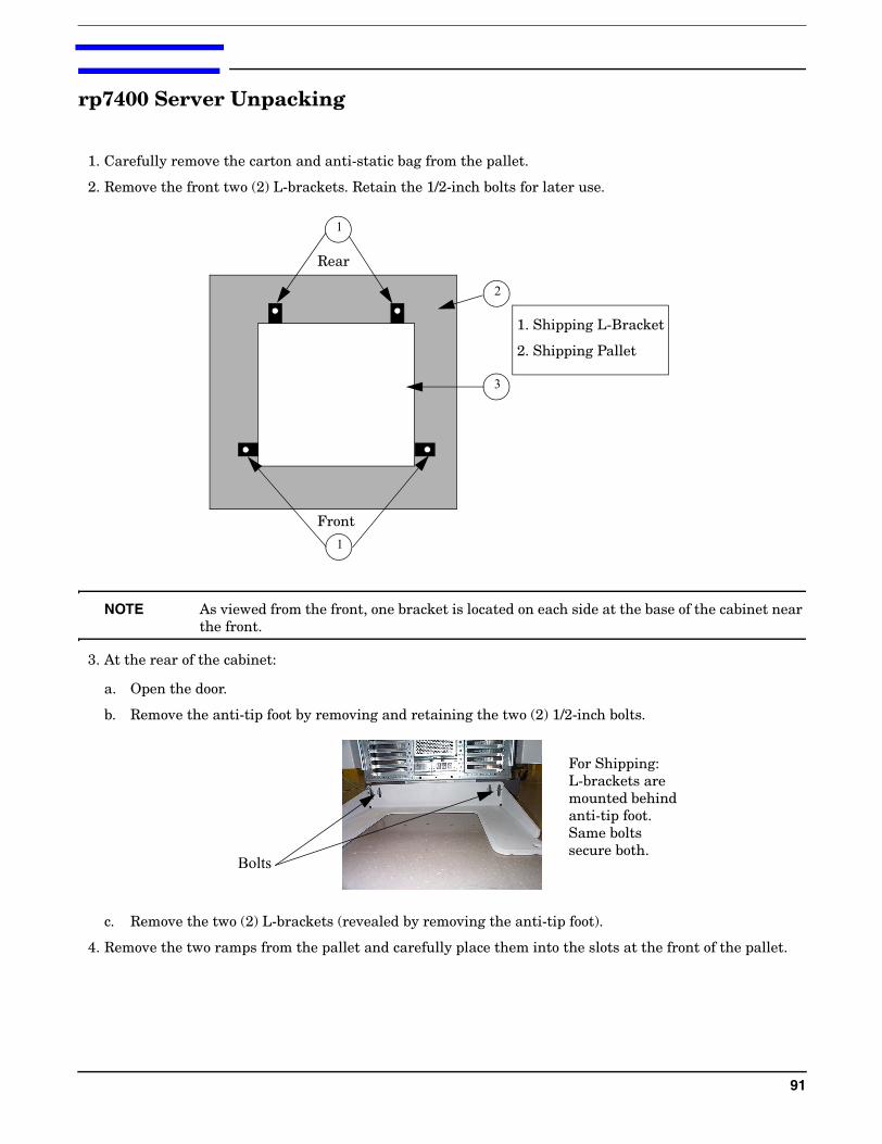
1. Carefully remove the carton and anti-static bag from the pallet.
2. Remove the front two (2) L-brackets. Retain the 1/2-inch bolts for later use.
NOTE As viewed from the front, one bracket is located on each side at the base of the cabinet near the front.
3. At the rear of the cabinet:
a. Open the door.
b. Remove the anti-tip foot by removing and retaining the two (2) 1/2-inch bolts.
c. Remove the two (2) L-brackets (revealed by removing the anti-tip foot).
4. Remove the two ramps from the pallet and carefully place them into the slots at the front of the pallet.
Rear
Front
1
1
2
3
1. Shipping L-Bracket
2. Shipping Pallet
Bolts
For Shipping: L-brackets are mounted behind anti-tip foot. Same bolts secure both.
91
rp7400 Server Unpacking
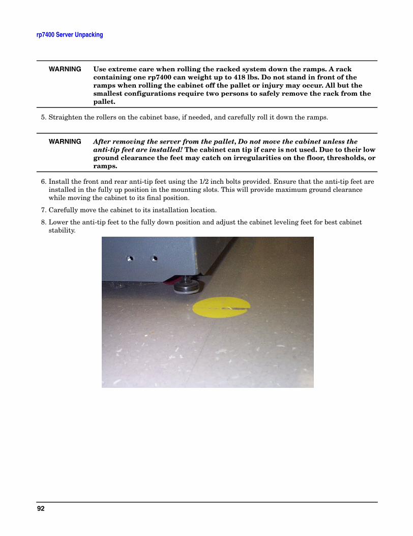
WARNING Use extreme care when rolling the racked system down the ramps. A rack containing one rp7400 can weight up to 418 lbs. Do not stand in front of the ramps when rolling the cabinet off the pallet or injury may occur. All but the smallest configurations require two persons to safely remove the rack from the pallet.
5. Straighten the rollers on the cabinet base, if needed, and carefully roll it down the ramps.
WARNING After removing the server from the pallet, Do not move the cabinet unless the anti-tip feet are installed! The cabinet can tip if care is not used. Due to their low ground clearance the feet may catch on irregularities on the floor, thresholds, or ramps.
6. Install the front and rear anti-tip feet using the 1/2 inch bolts provided. Ensure that the anti-tip feet are installed in the fully up position in the mounting slots. This will provide maximum ground clearance while moving the cabinet to its final position.
7. Carefully move the cabinet to its installation location.
8. Lower the anti-tip feet to the fully down position and adjust the cabinet leveling feet for best cabinet stability.
92
Console Cable Connections
The links below direct you to instructions covering how to install console connections on the rp7400 system.
Console Connections
HP 700 series system console connections.
Secure Web Console connections
LAN Console connections.
Direct Connect PC as a Console
93

Console Cable Connections
94
HP 700 Series System Console Configuration
The following describes the steps required to configure the HP 700 series terminal for VT-100 mode for operation with the rp7400 server.
Although any terminal capable of operating in VT-100 mode can be used, the HP700 series terminal is used here as an example because it is fairly common and it’s configuration is typical of many terminals currently in use.
HP700 VT-100 Mode Configuration
The following procedure outlines the steps to configure the HP700 series terminal for VT-100 operation.
NOTE You may use either the arrow keys or the tab key to move between the setting options on the screen.
1. Press [config keys] function key. [f8]
2. Press [terminal config] function key. [f5]
3. Move to Terminal ID and enter “vt100”.
4. Move to Set TermMode and, using the [Prev] and [Next] keys, select “EM100”.
5. Press the [config keys] function key. [f8]
6. Press the [ansi config] function key. [f6]
7. Move to “multipage” and, using the [Prev] and [Next] keys, select “yes”. (Enables screen scrolling).
8. Move to Backspace Del and, using the [Prev] and [Next] keys, select “Backspace/Del”.
9. Move to EM100 ID and, using the [Prev] and [Next] keys, select “EM100”.
95

HP 700 Series System Console Configuration
96
Core I/O Connections and Indicators
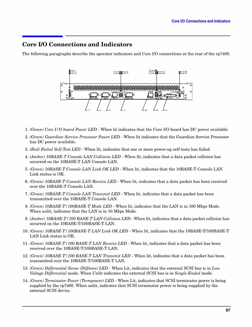
Core I/O Connections and IndicatorsThe following paragraphs describe the operator indicators and Core I/O connections at the rear of the rp7400.
1. (Green) Core I/O board Power LED - When lit indicates that the Core I/O board has DC power available.
2. (Green) Guardian Service Processor Power LED - When lit indicates that the Guardian Service Processor has DC power available.
3. (Red) Failed Self-Test LED - When lit, indicates that one or more power-up self tests has failed.
4. (Amber) 10BASE-T Console LAN Collision LED - When lit, indicates that a data packet collision has occurred on the 10BASE-T LAN Console LAN.
5. (Green) 10BASE-T Console LAN Link OK LED - When lit, indicates that the 10BASE-T Console LAN Link status is OK.
6. (Green) 10BASE-T Console LAN Receive LED - When lit, indicates that a data packet has been received over the 10BASE-T Console LAN.
7. (Green) 10BASE-T Console LAN Transmit LED - When lit, indicates that a data packet has been transmitted over the 10BASE-T Console LAN.
8. (Green) 10BASE-T/100BASE-T Mode LED - When lit, indicates that the LAN is in 100 Mbps Mode. When unlit, indicates that the LAN is in 10 Mbps Mode.
9. (Amber) 10BASE-T/100 BASE-T LAN Collision LED - When lit, indicates that a data packet collision has occurred on the 10BASE-T/100BASE-T LAN.
10. (Green) 10BASE-T/100BASE-T LAN Link OK LED - When lit, indicates that the 10BASE-T/100BASE-T LAN Link status is OK.
11. (Green) 10BASE-T/100 BASE-T LAN Receive LED - When lit, indicates that a data packet has been received over the 10BASE-T/100BASE-T LAN.
12. (Green) 10BASE-T/100 BASE-T LAN Transmit LED - When lit, indicates that a data packet has been transmitted over the 10BASE-T/100BASE-T LAN.
13. (Green) Differential Sense (Diffsens) LED - When Lit, indicates that the external SCSI bus is in Low Voltage Differential mode. When Unlit indicates the external SCSI bus is in Single-Ended mode.
14. (Green) Terminator Power (Termpower) LED - When Lit, indicates that SCSI terminator power is being supplied by the rp7400. When unlit, indicates that SCSI terminator power is being supplied by the external SCSI device.
97
Core I/O Connections and Indicators
15. Remote Console Serial Port (Modem) - Provides a 9-pin (Male), D-type, connector for a 9600 bps RS-232 serial port. For connection of a modem or other serial device.
16. Local Console Serial Port - Provides a 9-pin (Male), D-type, connector for a 9600 bps RS-232 serial port. For connection of a local system console/VT-100 terminal.
17. 10BASE-T LAN Console Port - Provides an RJ45 10BASE-T LAN Console connection.
18. UPS Only - Provides a 9-pin (Male), D-type, connector for a 9600 bps RS-232 serial port. For connection of a serial device or UPS.
19. 10BASE-T/100BASE-T LAN Port - Provides an RJ45 10BASE-T/100BASE-T System LAN connection.
20. GPS Reset Button (recessed) - When pressed causes a reset function to be executed in the Guardian Service Processor (GSP).
21. Ultra SCSI II 68-Pin Very High Density Computer Interface (VHDCI) - Provides connection to external SCSI devices. Autodetects Single ended (default) or Differential SCSI devices.
Console Connection and Configuration
The following describes the installation and configuration of the rp7400 system console.
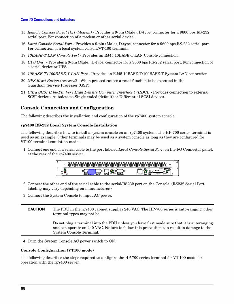
rp7400 RS-232 Local System Console Installation
The following describes how to install a system console on an rp7400 system. The HP-700 series terminal is used as an example. Other terminals may be used as a system console as long as they are configured for VT100 terminal emulation mode.
1. Connect one end of a serial cable to the port labeled Local Console Serial Port, on the I/O Connector panel, at the rear of the rp7400 server.
2. Connect the other end of the serial cable to the serial/RS232 port on the Console. (RS232 Serial Port labeling may vary depending on manufacturer.)
3. Connect the System Console to input AC power.
CAUTION The PDU in the rp7400 cabinet supplies 240 VAC. The HP-700 series is auto-ranging, other terminal types may not be.
Do not plug a terminal into the PDU unless you have first made sure that it is autoranging and can operate on 240 VAC. Failure to follow this precaution can result in damage to the System Console Terminal.
4. Turn the System Console AC power switch to ON.
Console Configuration (VT100 mode)
The following describes the steps required to configure the HP 700 series terminal for VT-100 mode for operation with the rp7400 server.
98
Core I/O Connections and Indicators
Although any terminal capable of operating in VT-100 mode can be used, the HP700 series terminal is used here as an example because it is fairly common and it’s configuration is typical of many terminals currently in use.
HP700 VT-100 Mode Configuration The following procedure outlines the steps to configure the HP700 series terminal for VT-100 operation.
NOTE You may use either the arrow keys or the tab key to move between the setting options on the screen.
1. Press [config keys] function key. [f8]
2. Press [terminal config] function key. [f5]
3. Move to Terminal ID and enter “vt100”.
4. Move to Set TermMode and, using the [Prev] and [Next] keys, select “EM100”.
5. Press the [config keys] function key. [f8]
6. Press the [ansi config] function key. [f6]
7. Move to “multipage” and, using the [Prev] and [Next] keys, select “yes”. (Enables screen scrolling).
8. Move to Backspace Del and, using the [Prev] and [Next] keys, select “Backspace/Del”.
9. Move to EM100 ID and, using the [Prev] and [Next] keys, select “EM100”.
99

Core I/O Connections and Indicators
100
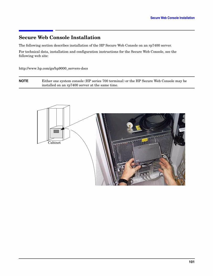
Secure Web Console Installation
Secure Web Console InstallationThe following section describes installation of the HP Secure Web Console on an rp7400 server.
For technical data, installation and configuration instructions for the Secure Web Console, see the following web site:
http://www.hp.com/go/hp9000_servers-docs
NOTE Either one system console (HP series 700 terminal) or the HP Secure Web Console may be installed on an rp7400 server at the same time.
Cabinet
101
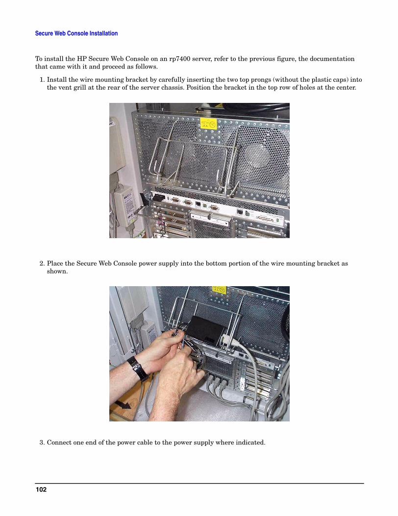
Secure Web Console Installation
To install the HP Secure Web Console on an rp7400 server, refer to the previous figure, the documentation that came with it and proceed as follows.
1. Install the wire mounting bracket by carefully inserting the two top prongs (without the plastic caps) into the vent grill at the rear of the server chassis. Position the bracket in the top row of holes at the center.
2. Place the Secure Web Console power supply into the bottom portion of the wire mounting bracket as shown.
3. Connect one end of the power cable to the power supply where indicated.
102

Secure Web Console Installation
4. Position the Web Console in the mounting bracket.
5. Connect the DC out cable from the power supply to the Web Console.
6. Connect one end (RJ-45) of the LAN cable, provided, to the LAN port on the secure web console unit.
7. Connect one end of the data/LAN cable to the port labeled Local Console Serial Port on the rp7400 server Core I/O panel.
CAUTION To prevent unauthorized access to your rp7400 system, do not connect the other end of the serial cable to the Secure Web Console until both the rp7400 and the Web Console have both been fully configured.
8. Connect the other end of the power cable into an available plug on a cabinet PDU.
9. Configure the Secure Web Console in accordance with the documentation that was provided with it or refer to http://eproducts.hp.com/prodinfo/mgmt_console.html
10. Once the Web Console has been properly configured, the remaining end of the serial cable between the rp7400 server and the Web Console may be connected.
103

Secure Web Console Installation
104
LAN Console
This section describes how to configure a notebook PC as a console via a LAN cable connection. This process uses a terminal emulator software package set to emulate a VT100 terminal.
NOTE The rp7400 server must first be configured via an HP700 system console before accessing it from a PC or UNIX system.
1. Connect a cable between your PC’s network adapter and the 10BaseT LAN Console port on the rear of the rp7400 server.
2. Launch your terminal emulator software and set emulation to VT100.
3. Connect to the rp7400 server by entering the IP address for its Guardian Service Processor (GSP) and press <ENTER> or <RETURN>
105

LAN Console
106
PC Direct Connect as System Console
This section describes how to configure a notebook PC as a console via a direct cable connection. This process uses a terminal emulator software package set to emulate a VT100 terminal.
1. Connect a serial port adapter cable between your PC’s serial port and the Local Console Serial Port on the rear of the rp7400 server.
2. You should have the HP-UX prompt at this point.
3. You can now log onto the system, or go into the GSP (with ctrl+b).
107

PC Direct Connect as System Console
108
SCSI Devices
SCSI DevicesThis section provides basic cabling and setup procedures for externally mounted SCSI devices.
External Media Devices
The rp7400 does not include internally mounted removable media devices (DVD-ROM, CDROM, or DDS Tape) as a standard part of the system.
The rp7400 provides an Ultra II, Low Voltage Differential (LVD), 68-pin Very High Density Computer Interconnect (VHDCI) SCSI port on the Core I/O connector panel. This connector if provided for the connection of external SCSI devices.
Cabinet mountable CDROM and DDS devices are available for the rp7400. Check your ordering guide for the correct devices, cables, and mounting enclosures.
HP Smart Rackmount Enclosure
The HP Smart Rackmount Enclosure (C4318SZ) provides the ability to rack mount and connect two HD 50-pin SCSI external media devices to the rp7400.
The Smart Rackmount Enclosure is connected to the rp7400 by a 68-pin, VHDCI connector on the Core I/O connector panel.
SCSI Termination
This section provides an overview of SCSI termination. The rp7400 has three SCSI buses. Two internal buses, off of a dual-channel controller and one external accessed through a 68-pin VHDCI connection on the Core I/O board.
Each internal bus contains one disk drive which is terminated.
The external bus is self terminating when no devices are present. If devices are connected the external bus must be properly terminated at the last physical device.
Refer to the rp7400 configuration guide and the manual for the device you are installing for proper termination procedures.
SCSI Termination General
Each physical end of a SCSI chain must be properly terminated. Termination requirements varies with the length of bus, number of devices, and bus speed. An improperly terminated SCSI bus can cause faults and bus data errors.
SCSI NarrowCan support up to 8 devices (0 - 7)Device 7 = Controller
SCSI WideCan support up to 16 devices (0 - 15)Device 15 = Controller
109
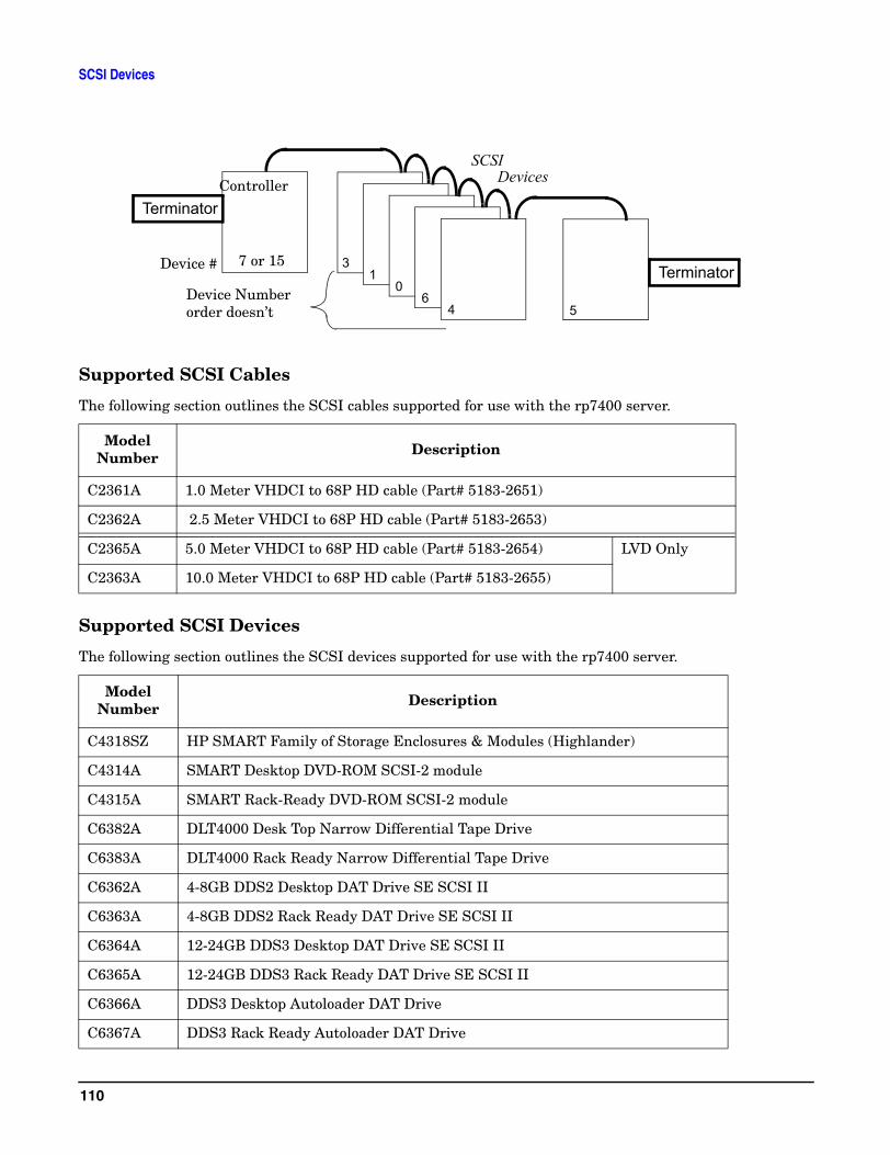
SCSI Devices
Supported SCSI Cables
The following section outlines the SCSI cables supported for use with the rp7400 server.
Supported SCSI Devices
The following section outlines the SCSI devices supported for use with the rp7400 server.
Model Number Description
C2361A 1.0 Meter VHDCI to 68P HD cable (Part# 5183-2651)
C2362A 2.5 Meter VHDCI to 68P HD cable (Part# 5183-2653)
C2365A 5.0 Meter VHDCI to 68P HD cable (Part# 5183-2654) LVD Only
C2363A 10.0 Meter VHDCI to 68P HD cable (Part# 5183-2655)
Model Number Description
C4318SZ HP SMART Family of Storage Enclosures & Modules (Highlander)
C4314A SMART Desktop DVD-ROM SCSI-2 module
C4315A SMART Rack-Ready DVD-ROM SCSI-2 module
C6382A DLT4000 Desk Top Narrow Differential Tape Drive
C6383A DLT4000 Rack Ready Narrow Differential Tape Drive
C6362A 4-8GB DDS2 Desktop DAT Drive SE SCSI II
C6363A 4-8GB DDS2 Rack Ready DAT Drive SE SCSI II
C6364A 12-24GB DDS3 Desktop DAT Drive SE SCSI II
C6365A 12-24GB DDS3 Rack Ready DAT Drive SE SCSI II
C6366A DDS3 Desktop Autoloader DAT Drive
C6367A DDS3 Rack Ready Autoloader DAT Drive
Controller
Terminator37 or 15Device #1
06
4 5
Terminator
Device Number order doesn’t
SCSI Devices
110
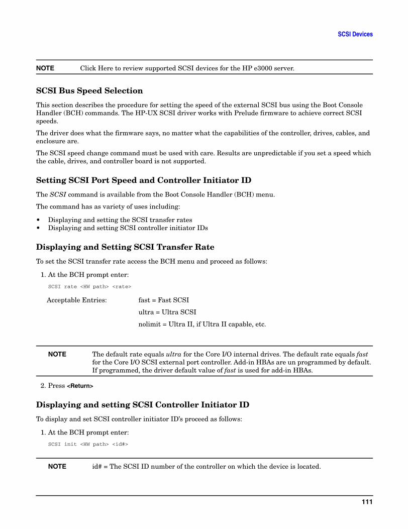
SCSI Devices
NOTE Click Here to review supported SCSI devices for the HP e3000 server.
SCSI Bus Speed Selection
This section describes the procedure for setting the speed of the external SCSI bus using the Boot Console Handler (BCH) commands. The HP-UX SCSI driver works with Prelude firmware to achieve correct SCSI speeds.
The driver does what the firmware says, no matter what the capabilities of the controller, drives, cables, and enclosure are.
The SCSI speed change command must be used with care. Results are unpredictable if you set a speed which the cable, drives, and controller board is not supported.
Setting SCSI Port Speed and Controller Initiator ID
The SCSI command is available from the Boot Console Handler (BCH) menu.
The command has as variety of uses including:
• Displaying and setting the SCSI transfer rates• Displaying and setting SCSI controller initiator IDs
Displaying and Setting SCSI Transfer Rate
To set the SCSI transfer rate access the BCH menu and proceed as follows:
1. At the BCH prompt enter:
SCSI rate <HW path> <rate>
NOTE The default rate equals ultra for the Core I/O internal drives. The default rate equals fast for the Core I/O SCSI external port controller. Add-in HBAs are un programmed by default. If programmed, the driver default value of fast is used for add-in HBAs.
2. Press <Return>
Displaying and setting SCSI Controller Initiator ID
To display and set SCSI controller initiator ID’s proceed as follows:
1. At the BCH prompt enter:
SCSI init <HW path> <id#>
NOTE id# = The SCSI ID number of the controller on which the device is located.
Acceptable Entries: fast = Fast SCSI
ultra = Ultra SCSI
nolimit = Ultra II, if Ultra II capable, etc.
111
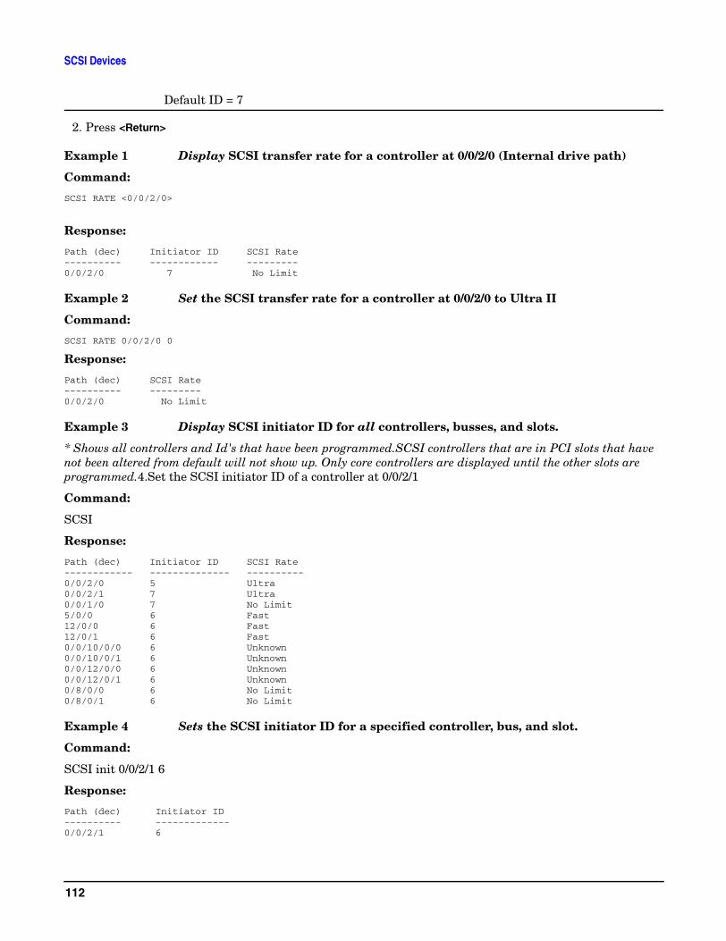
SCSI Devices
Default ID = 7
2. Press <Return>
Example 1 Display SCSI transfer rate for a controller at 0/0/2/0 (Internal drive path)
Command:
SCSI RATE <0/0/2/0>
Response:
Path (dec) Initiator ID SCSI Rate---------- ------------ ---------0/0/2/0 7 No Limit
Example 2 Set the SCSI transfer rate for a controller at 0/0/2/0 to Ultra II
Command:
SCSI RATE 0/0/2/0 0
Response:
Path (dec) SCSI Rate---------- ---------0/0/2/0 No Limit
Example 3 Display SCSI initiator ID for all controllers, busses, and slots.
* Shows all controllers and Id's that have been programmed.SCSI controllers that are in PCI slots that have not been altered from default will not show up. Only core controllers are displayed until the other slots are programmed.4.Set the SCSI initiator ID of a controller at 0/0/2/1
Command:
SCSI
Response:
Path (dec) Initiator ID SCSI Rate------------ -------------- ----------0/0/2/0 5 Ultra0/0/2/1 7 Ultra0/0/1/0 7 No Limit5/0/0 6 Fast12/0/0 6 Fast12/0/1 6 Fast0/0/10/0/0 6 Unknown 0/0/10/0/1 6 Unknown 0/0/12/0/0 6 Unknown 0/0/12/0/1 6 Unknown 0/8/0/0 6 No Limit 0/8/0/1 6 No Limit
Example 4 Sets the SCSI initiator ID for a specified controller, bus, and slot.
Command:
SCSI init 0/0/2/1 6
Response:
Path (dec) Initiator ID---------- -------------0/0/2/1 6
112
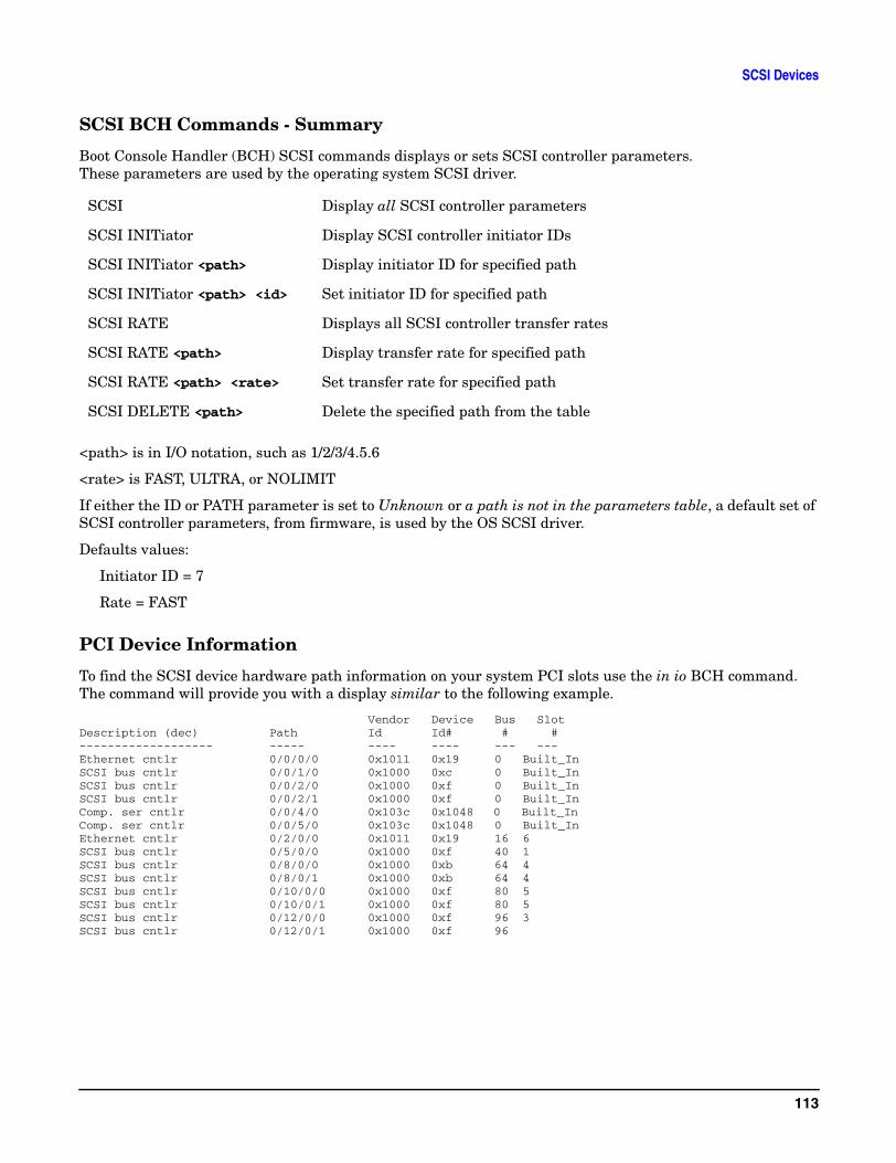
SCSI Devices
SCSI BCH Commands - Summary
Boot Console Handler (BCH) SCSI commands displays or sets SCSI controller parameters. These parameters are used by the operating system SCSI driver.
<path> is in I/O notation, such as 1/2/3/4.5.6
<rate> is FAST, ULTRA, or NOLIMIT
If either the ID or PATH parameter is set to Unknown or a path is not in the parameters table, a default set of SCSI controller parameters, from firmware, is used by the OS SCSI driver.
Defaults values:
Initiator ID = 7
Rate = FAST
PCI Device Information
To find the SCSI device hardware path information on your system PCI slots use the in io BCH command. The command will provide you with a display similar to the following example.
Vendor Device Bus SlotDescription (dec) Path Id Id# # #------------------- ----- ---- ---- --- ---Ethernet cntlr 0/0/0/0 0x1011 0x19 0 Built_InSCSI bus cntlr 0/0/1/0 0x1000 0xc 0 Built_InSCSI bus cntlr 0/0/2/0 0x1000 0xf 0 Built_InSCSI bus cntlr 0/0/2/1 0x1000 0xf 0 Built_InComp. ser cntlr 0/0/4/0 0x103c 0x1048 0 Built_InComp. ser cntlr 0/0/5/0 0x103c 0x1048 0 Built_InEthernet cntlr 0/2/0/0 0x1011 0x19 16 6SCSI bus cntlr 0/5/0/0 0x1000 0xf 40 1SCSI bus cntlr 0/8/0/0 0x1000 0xb 64 4SCSI bus cntlr 0/8/0/1 0x1000 0xb 64 4SCSI bus cntlr 0/10/0/0 0x1000 0xf 80 5SCSI bus cntlr 0/10/0/1 0x1000 0xf 80 5SCSI bus cntlr 0/12/0/0 0x1000 0xf 96 3SCSI bus cntlr 0/12/0/1 0x1000 0xf 96
SCSI Display all SCSI controller parameters
SCSI INITiator Display SCSI controller initiator IDs
SCSI INITiator <path> Display initiator ID for specified path
SCSI INITiator <path> <id> Set initiator ID for specified path
SCSI RATE Displays all SCSI controller transfer rates
SCSI RATE <path> Display transfer rate for specified path
SCSI RATE <path> <rate> Set transfer rate for specified path
SCSI DELETE <path> Delete the specified path from the table
113

SCSI Devices
114
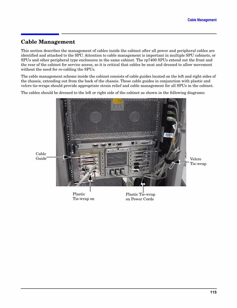
Cable Management
Cable ManagementThis section describes the management of cables inside the cabinet after all power and peripheral cables are identified and attached to the SPU. Attention to cable management is important in multiple SPU cabinets, or SPUs and other peripheral type enclosures in the same cabinet. The rp7400 SPUs extend out the front and the rear of the cabinet for service access, so it is critical that cables be neat and dressed to allow movement without the need for re-cabling the SPUs.
The cable management scheme inside the cabinet consists of cable guides located on the left and right sides of the chassis, extending out from the back of the chassis. These cable guides in conjunction with plastic and velcro tie-wraps should provide appropriate strain relief and cable management for all SPUs in the cabinet.
The cables should be dressed to the left or right side of the cabinet as shown in the following diagrams:
Cable Guide
Plastic Tie-wrap on
Plastic Tie-wrap on Power Cords
Velcro Tie-wrap
115
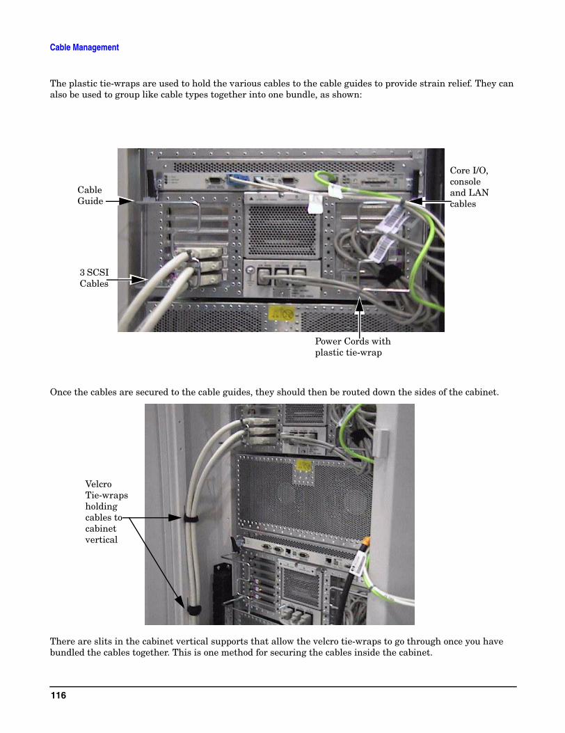
Cable Management
The plastic tie-wraps are used to hold the various cables to the cable guides to provide strain relief. They can also be used to group like cable types together into one bundle, as shown:
Once the cables are secured to the cable guides, they should then be routed down the sides of the cabinet.
There are slits in the cabinet vertical supports that allow the velcro tie-wraps to go through once you have bundled the cables together. This is one method for securing the cables inside the cabinet.
Cable Guide
3 SCSI Cables
Power Cords with plastic tie-wrap
Core I/O, console and LAN cables
Velcro Tie-wraps holding cables to cabinet vertical
116
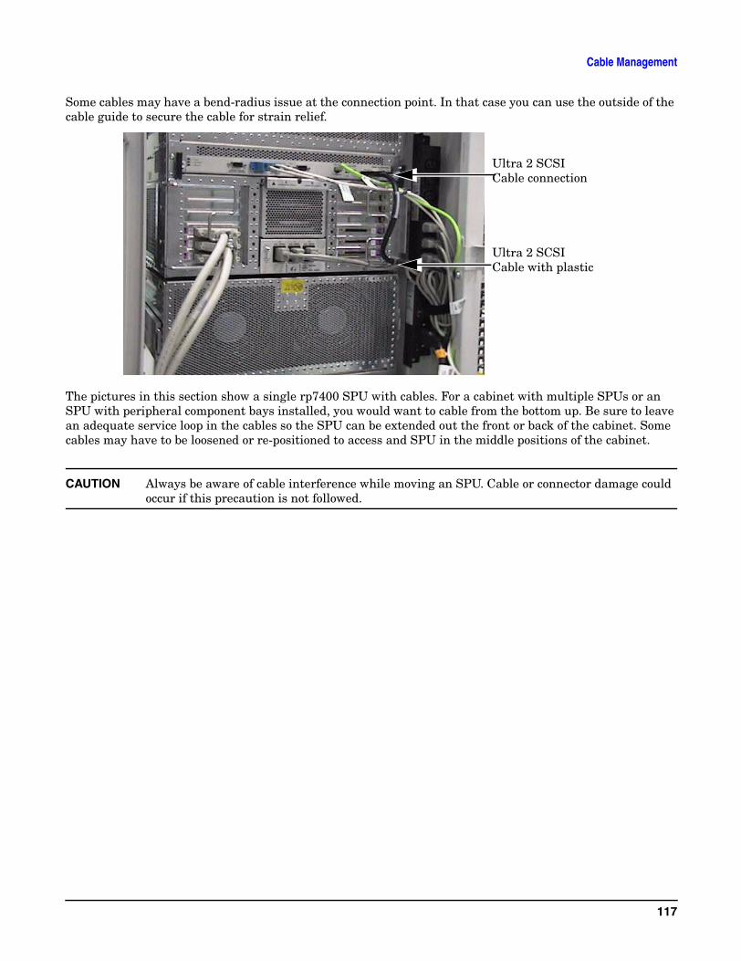
Cable Management
Some cables may have a bend-radius issue at the connection point. In that case you can use the outside of the cable guide to secure the cable for strain relief.
The pictures in this section show a single rp7400 SPU with cables. For a cabinet with multiple SPUs or an SPU with peripheral component bays installed, you would want to cable from the bottom up. Be sure to leave an adequate service loop in the cables so the SPU can be extended out the front or back of the cabinet. Some cables may have to be loosened or re-positioned to access and SPU in the middle positions of the cabinet.
CAUTION Always be aware of cable interference while moving an SPU. Cable or connector damage could occur if this precaution is not followed.
Ultra 2 SCSI Cable connection
Ultra 2 SCSI Cable with plastic
117

Cable Management
118
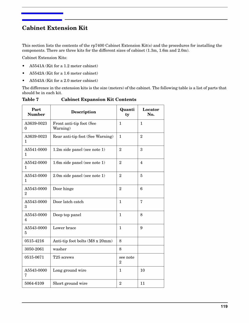
Cabinet Extension Kit
This section lists the contents of the rp7400 Cabinet Extension Kit(s) and the procedures for installing the components. There are three kits for the different sizes of cabinet (1.3m, 1.6m and 2.0m).
Cabinet Extension Kits:
• A5541A (Kit for a 1.2 meter cabinet)
• A5542A (Kit for a 1.6 meter cabinet)
• A5543A (Kit for a 2.0 meter cabinet)
The difference in the extension kits is the size (meters) of the cabinet. The following table is a list of parts that should be in each kit.
Table 7 Cabinet Expansion Kit Contents
Part Number Description Quanti
tyLocator
No.
A3639-00230
Front anti-tip foot (See Warning)
1 1
A3639-00231
Rear anti-tip foot (See Warning) 1 2
A5541-00001
1.2m side panel (see note 1) 2 3
A5542-00001
1.6m side panel (see note 1) 2 4
A5543-00001
2.0m side panel (see note 1) 2 5
A5543-00002
Door hinge 2 6
A5543-00003
Door latch catch 1 7
A5543-00004
Deep top panel 1 8
A5543-00005
Lower brace 1 9
0515-4216 Anti-tip foot bolts (M8 x 20mm) 8
3050-2061 washer 8
0515-0671 T25 screws see note 2
A5543-00007
Long ground wire 1 10
5064-6109 Short ground wire 2 11
119
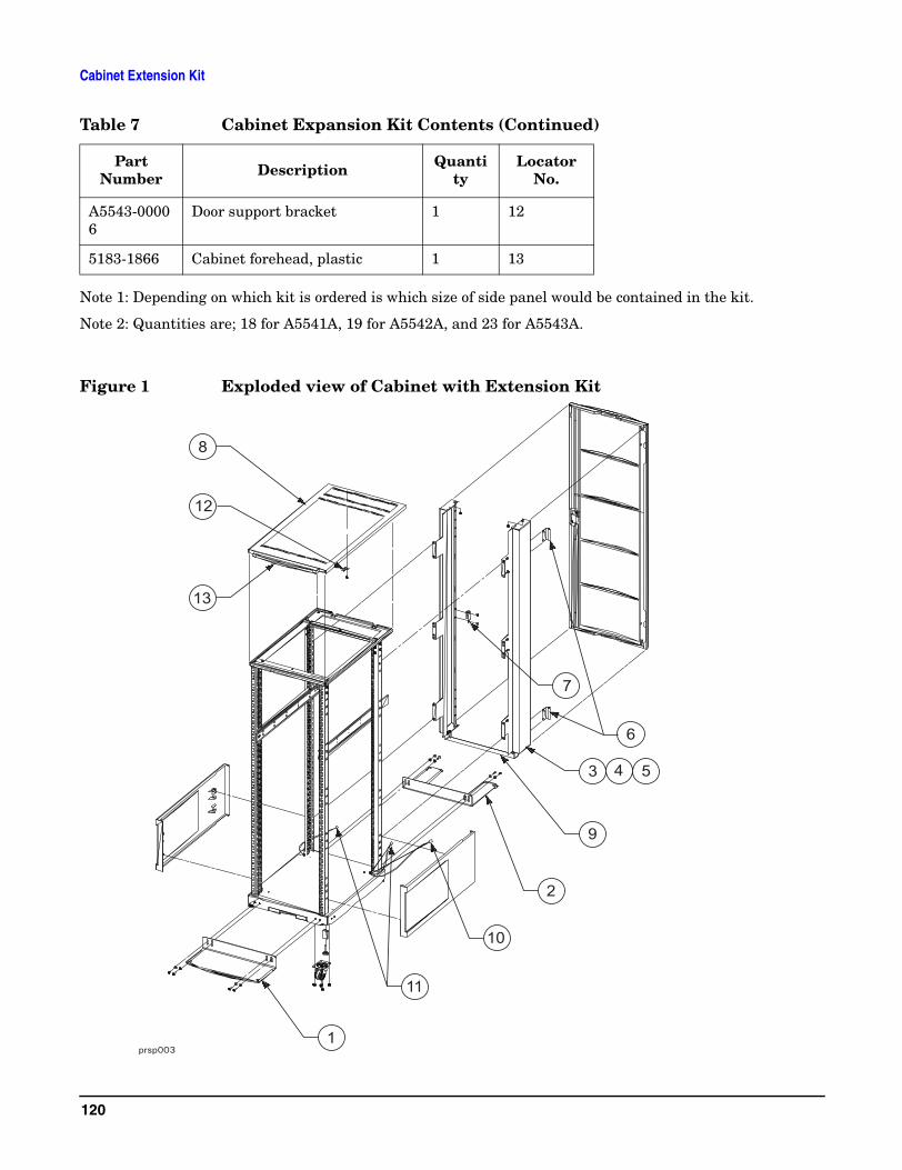
Cabinet Extension Kit
Note 1: Depending on which kit is ordered is which size of side panel would be contained in the kit.
Note 2: Quantities are; 18 for A5541A, 19 for A5542A, and 23 for A5543A.
Figure 1 Exploded view of Cabinet with Extension Kit
A5543-00006
Door support bracket 1 12
5183-1866 Cabinet forehead, plastic 1 13
Table 7 Cabinet Expansion Kit Contents (Continued)
Part Number Description Quanti
tyLocator
No.
120
Cabinet Extension Kit
CAUTION Once the cabinet has been fitted with the extension kit the original shipping material will no longer work. All new shipping material is needed, pallet, ramps, box, and top cap. DO NOT try to use the original shipping material with the new cabinet.
The cabinet must either be packaged with the new material or shipped via padded van.
WARNING The anti-tip feet must be installed to ensure cabinet stability. Failure to do so could result in injury and equipment damage.
121
Cabinet Extension Kit
Before installing the cabinet extension kit parts, you must first remove parts from the existing cabinet. Some of the parts (see note) removed are not usable with the cabinet extension kit or the rp7400 system.
Preparing the Cabinet
1. Remove the cabinet plastic, side panels, by pulling them away from the cabinet (snap releases from the front).
2. Disconnect the ground wire from the back door.
3. Remove the rear door by opening it at approximately a 45 degree angle. Grasp the door and lift it up to disengage the door hinge pins.
4. Remove the top panel by pushing it forward from the rear, then lifting it up and off the cabinet.
5. Remove the door support bracket from the top of the cabinet frame.
6. Remove the door hinges from the cabinet vertical rails.
7. Remove the door latch plate from the cabinet vertical rails.
8. Remove any column mounted PDUs.
NOTE The cabinet top panel, door hinges, and door latch plate, can be discarded, they are not used on a cabinet with the extension kit installed.
Cabinet Expansion Kit Installation
1. From the back, place the deep top panel over the top of the cabinet, with the front angled down and slightly forward so the tabs on the top panel can slide back into the slots on the front of the cabinet. Lower the back of the top panel down and pull the top panel toward the back until it is fully seated on top of the cabinet.
2. Snap the new, plastic cabinet forehead onto the front edge of the top panel.
3. Start a screw into the screw hole under the lower edge of the top panel. Do not tighten it, but make sure it is in by two or three turns.
4. Hang a side panel from either the left or right side screw inserted in the top panel in step 3.
5. Insert five (5) T25 mounting screws through the side panel into the cabinet vertical frame. Note, for the 1.2m (A5541-00001) side panel, you will only insert three (3) T25 screws.
6. Repeat steps 3 through 5 for the other side.
7. Place the lower brace across the bottom of the side panels and insert four (two on each side) T25 screws through the brace into the side panels.
8. Tighten all the T25 screws.
9. Attach the door hinges to the left side panel with four (two for each hinge) T25 screws.
10. Attach the door latch to the right side panel with two (2) T25 screws.
11. Attach the door stabilizer to the under side of the top panel with one (1) T25 screw.
122
Cabinet Extension Kit
12. Replace the cabinet plastic, side panels.
13. Attach the two short ground wires (one for each side), between the cabinet frame and the extension side panels.
14. Attach the long ground wire between the cabinet frame and the rear door
WARNING Do not install the outer rails or an N Class SPU without first installing the front and rear anti-tip feet.
Anti-Tip Feet Installation
Before any product is installed in the cabinet and the cabinet has been positioned at the installation site, the anti-tip feet need to be installed for safety and cabinet stability reasons.
1. Lower the cabinet leveler feet at all four corners of the cabinet. Be sure the leveler feet contact the floor surface.
2. Place the solid front anti-tip foot so the slotted holes align with the threaded holes on the bottom edge of the cabinet frame.
3. Insert four bolts and washers (two each side) through the anti-tip foot into the cabinet frame.
4. Press down on the anti-tip foot until it touches the floor, then tighten the bolts.
5. Place the rear anti-tip foot so the cable management slot aligns with the hole in the raised floor.
6. Insert four bolts and washers (two each side) through the anti-tip foot into the cabinet frame.
7. Press down on the anti-tip foot until it touches the floor, then tighten the bolts.
The cabinet is now ready for one or more rp7400 SPUs, or other computer components to be installed.
123

Cabinet Extension Kit
124
rp7400 Server Boot up
rp7400 Server Boot upWhen booting up your system, for the first time, the first thing you should to is configure the Guardian Service processor (GSP). Failure to configure the GSP will leave the system vulnerable to unauthorized. access.
Configuring the Guardian Service Processor (GSP)
The Guardian Service Processor (GSP) is a resident processor within the system that allows the local or remote system administrator to monitor and perform administrator functions. This section provides configuration procedures that will instruct you to:
• Configure the LAN port
• Add or delete users (maximum of 20)
• Change the default GSP configuration
Go to the appropriate section for the task that you wish to accomplish.
Configuring the GSP LAN Port
Perform the LAN configuration from the systems local port (either console or the HP secure web console).
NOTE The GSP has a separate LAN port from the system LAN port. It will need a separate LAN drop, IP address, and networking information from the port used by HP-UX. Before starting this procedure, you will need to know the following information:
• I.P. address (for GSP)
• Subnet mask
• Gateway address
• Hostname (this is used when messages are logged or printed)
To configure the GSP LAN port, perform the following steps:
1. Go into the GSP with the ctrl+b entry.
2. At the GSP prompt, enter the LAN Configuration (lc) command:
GSP> lc
The lc command will start a series of prompts. Respond to each prompt with the appropriate information.
125
rp7400 Server Boot up
Adding Users
The GSP can only have a maximum of 20 users (one administrator and 19 operators). By design, the first user added to the GSP becomes the GSP administrator. Only the GSP administrator can add or remove users or change the GSP configuration.
NOTE Before starting this procedure, you will need to know the following information:
• User’s name
• Organization’s name
• Login name
• User’s password
To add a user, perform the following steps:
1. Go into the GSP with the ctrl+b entry.
2. At the GSP prompt, enter the Security options and access control (SO) command:
GSP> so
3. The first prompt you will see with the so command is for GSP wide parameters:
GSP wide parameters are:Login Timeout: 1 minutes.. Number of password Faults allowed: 3. Flow Control Timeout: 5 minutes.Do you want to modify the GSP wide parameters? (Y / [N]) __
At this point you can modify the GSP wide parameters, or continue with adding users. To add users, respond N for no.
NOTE If this is the first time users are being added, the first user added will be the GSP administrator.
If this is not the first time you are adding users (you are adding additional users), you will need to step through all current users to reach the next available user prompt.
4. The next prompt that appears will ask the following question:
Do you want to modify the user number 1 parameters? (Y/[N]/Q to quit) __
Follow the series of prompts to enter all the required fields for adding a user.
CAUTION Be sure to read each prompt carefully and enter the correct response. A missed or incorrect entry could deny entry to that user.
126
rp7400 Server Boot up
An example of an added users information would be:
. User’s Name: Joe Smith
. Organization’s Name: IT Support
. Dial-back configuration: Disabled
. Access Level: Operator
. Mode: multiple
. User’s state: enabled
For the number 1 user, the Access level is administrator. The Mode entry of single only allows entry for that user one time, then access will be denied. A Mode entry of multiple allows unlimited entries into the GSP.
Removing Users
You can remove (disable) a GSP user with the same Security options and access control (SO) command used to add a user.
To remove a user, perform the following steps:
1. Go into the GSP with the ctrl+b entry.
2. At the GSP prompt, enter the Security options and access control (SO) command:
GSP> so
3. The first prompt you will see with the so command is for GSP wide parameters:
GSP wide parameters are:. Login Timeout: 1 minutes.. Number of password Faults allowed: 3. Flow Control Timeout: 5 minutes.
Do you want to modify the GSP wide parameters? (Y / [N]) __
At this point you can modify the GSP wide parameters, or continue with removing a user. To remove users, respond N for no.
NOTE You will have to step through each user number until you reach the user to be removed.
4. When you access the number of the user to be removed, you must change the data in the prompts for that number.
It is important that, at a minimum, you need to modify the User’s state to Disabled.
127
rp7400 Server Boot up
Changing the Default GSP Configuration
This section describes the process of changing GSP default configurations. To change the GSP default configuration, perform the following steps:
1. Go into the GSP with the ctrl+b entry.
2. At the GSP prompt, enter the Default Configuration (dc) command:
GSP> dc
3. Follow the prompts for the dc command, and be sure to have the change information available.
CAUTION When the Security configuration is reset, all users are removed, including the GSP administrator. It also disables the remote. Remote must be re-enabled through the main console using the Enable Remote (er) command.
128
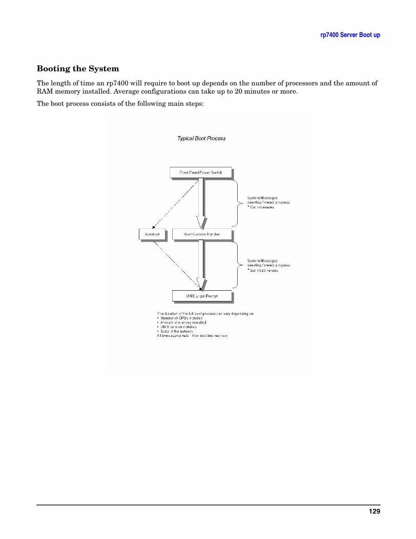
rp7400 Server Boot up
Booting the System
The length of time an rp7400 will require to boot up depends on the number of processors and the amount of RAM memory installed. Average configurations can take up to 20 minutes or more.
The boot process consists of the following main steps:
129

rp7400 Server Boot up
During the Boot process a variety of errors or problems can occur as follows:
Initial Power-up
The following section will describe the process of applying power to the rp7400 server and booting the system up to the UNIX Login prompt. The amount of time it takes to go through self-test and boot the system will vary widely depending on hardware configuration. The following provides a “typical” procedure yours may vary depending on software and hardware installed.
1. Apply AC Power to the system console, if you haven't already done so.
130
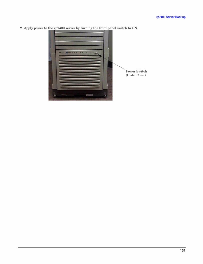
rp7400 Server Boot up
2. Apply power to the rp7400 server by turning the front panel switch to ON.
Power Switch(Under Cover)
131
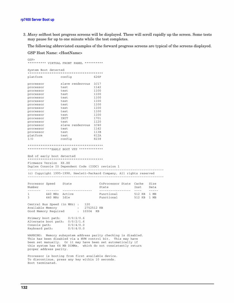
rp7400 Server Boot up
3. Many selftest boot progress screens will be displayed. These will scroll rapidly up the screen. Some tests may pause for up to one minute while the test completes.
The following abbreviated examples of the forward progress screens are typical of the screens displayed.
GSP Host Name: <HostName>
GSP>********** VIRTUAL FRONT PANEL **********
System Boot detected*****************************************platform config 626F
processor slave rendezvous 1C17processor test 1142processor test 1100processor test 1100processor test 1100processor test 1100processor test 1100processor test 1100processor test 1100processor test 1100processor INIT 1701processor test 1120processor slave rendezvous 1C40processor test 1142processor test 113Bplatform test 612AI/O config 8238
******************************************************EARLY BOOT VFP *************
End of early boot detected*****************************************Firmware Version XX.XXDuplex Console IO Dependent Code (IODC) revision 1--------------------------------------------------------------------------(c) Copyright 1995-1998, Hewlett-Packard Company, All rights reserved--------------------------------------------------------------------------
Processor Speed State CoProcessor State Cache SizeNumber State Inst Data------- ------- ---------------- ----------------- ---- -----1 440 MHz Active Functional 512 KB 1 MB3 440 MHz Idle Functional 512 KB 1 MB
Central Bus Speed (in MHz) : 120Available Memory : 2752512 KBGood Memory Required : 10304 KB
Primary boot path: 0/0/2/0.6Alternate boot path: 0/0/2/1.6Console path: 0/0/4/0.0Keyboard path: 0/0/4/0.0
WARNING: Memory subsystem address parity checking is disabled.This has been disabled via a NVM control bit. This may have been set manually. Or it may have been set automatically if this system has 64 MB DIMMs, which do not consistently returnproper address parity.
Processor is booting from first available device.To discontinue, press any key within 10 seconds.Boot terminated.
132
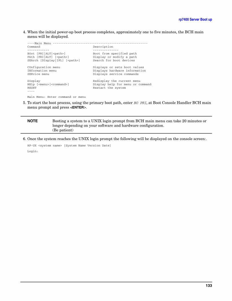
rp7400 Server Boot up
4. When the initial power-up boot process completes, approximately one to five minutes, the BCH main menu will be displayed.
----Main Menu ----------------------------------------------------Command Description------------ --------------BOot [PRI|ALT|<path>] Boot from specified pathPAth [PRI|ALT] [<path>] Display or modify a pathSEArch [DIsplay|IPL] [<path>] Search for boot devices
COnfiguration menu Displays or sets boot valuesINformation menu Displays hardware informationSERvice menu Displays service commands
DIsplay Redisplay the current menuHElp [<menu>|<command>] Display help for menu or commandRESET Restart the system----
Main Menu: Enter command or menu
5. To start the boot process, using the primary boot path, enter BO PRI, at Boot Console Handler BCH main menu prompt and press <ENTER>.
NOTE Booting a system to a UNIX login prompt from BCH main menu can take 20 minutes or longer depending on your software and hardware configuration.(Be patient)
6. Once the system reaches the UNIX login prompt the following will be displayed on the console screen:.
HP-UX <system name> [System Name Version Date]
Login:
133

rp7400 Server Boot up
134
Accessing Guardian Service Processor Internal Port
Accessing Guardian Service Processor Internal PortThe Guardian Service Processor (GSP) internal port can be used as a “back door” to reset security options in case the GSP administrator password is forgotten, for example. It can also be used in order to upgrade the GSP firmware from an HP-UX session. The internal port needs to be configured in order to use it.
NOTE Updating the Guardian Service Processor via the Internal Port is not supported on the HP e3000 server.
1. On the system, the GSP internal port should be /dev/tty1p0.
2. SAM does not configure the GSP internal port.
3. If the device file is not present, it can be created as follows:
#cd/dev#mknod tty1p0 c 1 0x010000
4. Since this allows unrestricted access to the GSP and bypasses GSP security features (no user or password required). Make sure to delete this device file when you have finished using it.
5. The internal port can be accessed via terminal emulators such as cu. To use cu, you need the follow entries (the entries must be exactly as shown):
/usr/lib/uucp/Systems needs the following entry:
gspiport Any;5 gspiport,f900 - ‘‘‘‘\r\d\r\d\r ogin:-BREAK-ogin: uucp asswrd: uucp-BREAK-ogin: uucp asswrd: uucp
The spelling looks unusual, but it needs to be exactly as shown.
/usr/lib/uucp/Devices needs the following entry:
gspiport tty1p0 - 9600 direct
6. when all of the configuration is done, you should be able to access the GSP internal port with the cu command:
cu-1/dev/tty1p0
7. To terminate the cu session, use “~.” [return]
8. Kermit can also be used to access the special device file. See the kermit web pages for details.
CAUTION Securing the /dev/tty1p0 device file with root capabilities will not prevent non-root users from accessing the GSP internal port. This is due to the fact that cu and kermit carry root access and run with the sticky bit enabled.
To secure the internal port from unauthorized use, be sure to remove the /dev/tty1p0 file after using it.
135

Accessing Guardian Service Processor Internal Port
136
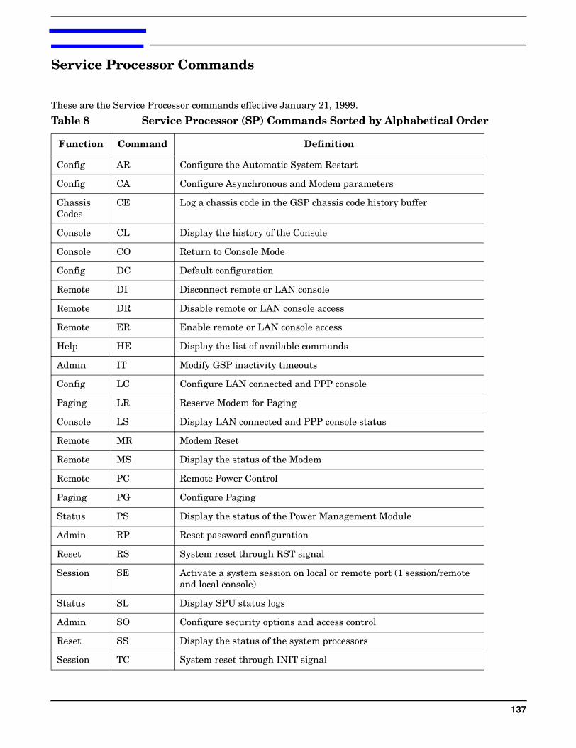
Service Processor Commands
These are the Service Processor commands effective January 21, 1999.
Table 8 Service Processor (SP) Commands Sorted by Alphabetical Order
Function Command Definition
Config AR Configure the Automatic System Restart
Config CA Configure Asynchronous and Modem parameters
Chassis Codes
CE Log a chassis code in the GSP chassis code history buffer
Console CL Display the history of the Console
Console CO Return to Console Mode
Config DC Default configuration
Remote DI Disconnect remote or LAN console
Remote DR Disable remote or LAN console access
Remote ER Enable remote or LAN console access
Help HE Display the list of available commands
Admin IT Modify GSP inactivity timeouts
Config LC Configure LAN connected and PPP console
Paging LR Reserve Modem for Paging
Console LS Display LAN connected and PPP console status
Remote MR Modem Reset
Remote MS Display the status of the Modem
Remote PC Remote Power Control
Paging PG Configure Paging
Status PS Display the status of the Power Management Module
Admin RP Reset password configuration
Reset RS System reset through RST signal
Session SE Activate a system session on local or remote port (1 session/remote and local console)
Status SL Display SPU status logs
Admin SO Configure security options and access control
Reset SS Display the status of the system processors
Session TC System reset through INIT signal
137
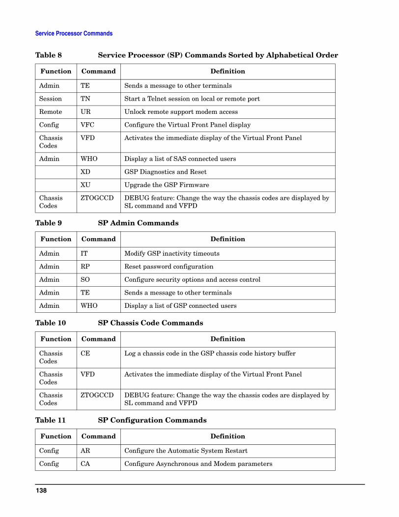
Service Processor Commands
Admin TE Sends a message to other terminals
Session TN Start a Telnet session on local or remote port
Remote UR Unlock remote support modem access
Config VFC Configure the Virtual Front Panel display
Chassis Codes
VFD Activates the immediate display of the Virtual Front Panel
Admin WHO Display a list of SAS connected users
XD GSP Diagnostics and Reset
XU Upgrade the GSP Firmware
Chassis Codes
ZTOGCCD DEBUG feature: Change the way the chassis codes are displayed by SL command and VFPD
Table 9 SP Admin Commands
Function Command Definition
Admin IT Modify GSP inactivity timeouts
Admin RP Reset password configuration
Admin SO Configure security options and access control
Admin TE Sends a message to other terminals
Admin WHO Display a list of GSP connected users
Table 10 SP Chassis Code Commands
Function Command Definition
Chassis Codes
CE Log a chassis code in the GSP chassis code history buffer
Chassis Codes
VFD Activates the immediate display of the Virtual Front Panel
Chassis Codes
ZTOGCCD DEBUG feature: Change the way the chassis codes are displayed by SL command and VFPD
Table 11 SP Configuration Commands
Function Command Definition
Config AR Configure the Automatic System Restart
Config CA Configure Asynchronous and Modem parameters
Table 8 Service Processor (SP) Commands Sorted by Alphabetical Order
Function Command Definition
138
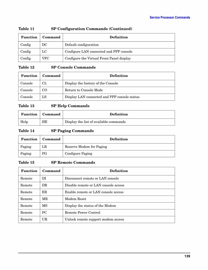
Service Processor Commands
Config DC Default configuration
Config LC Configure LAN connected and PPP console
Config VFC Configure the Virtual Front Panel display
Table 12 SP Console Commands
Function Command Definition
Console CL Display the history of the Console
Console CO Return to Console Mode
Console LS Display LAN connected and PPP console status
Table 13 SP Help Commands
Function Command Definition
Help HE Display the list of available commands
Table 14 SP Paging Commands
Function Command Definition
Paging LR Reserve Modem for Paging
Paging PG Configure Paging
Table 15 SP Remote Commands
Function Command Definition
Remote DI Disconnect remote or LAN console
Remote DR Disable remote or LAN console access
Remote ER Enable remote or LAN console access
Remote MR Modem Reset
Remote MS Display the status of the Modem
Remote PC Remote Power Control
Remote UR Unlock remote support modem access
Table 11 SP Configuration Commands (Continued)
Function Command Definition
139
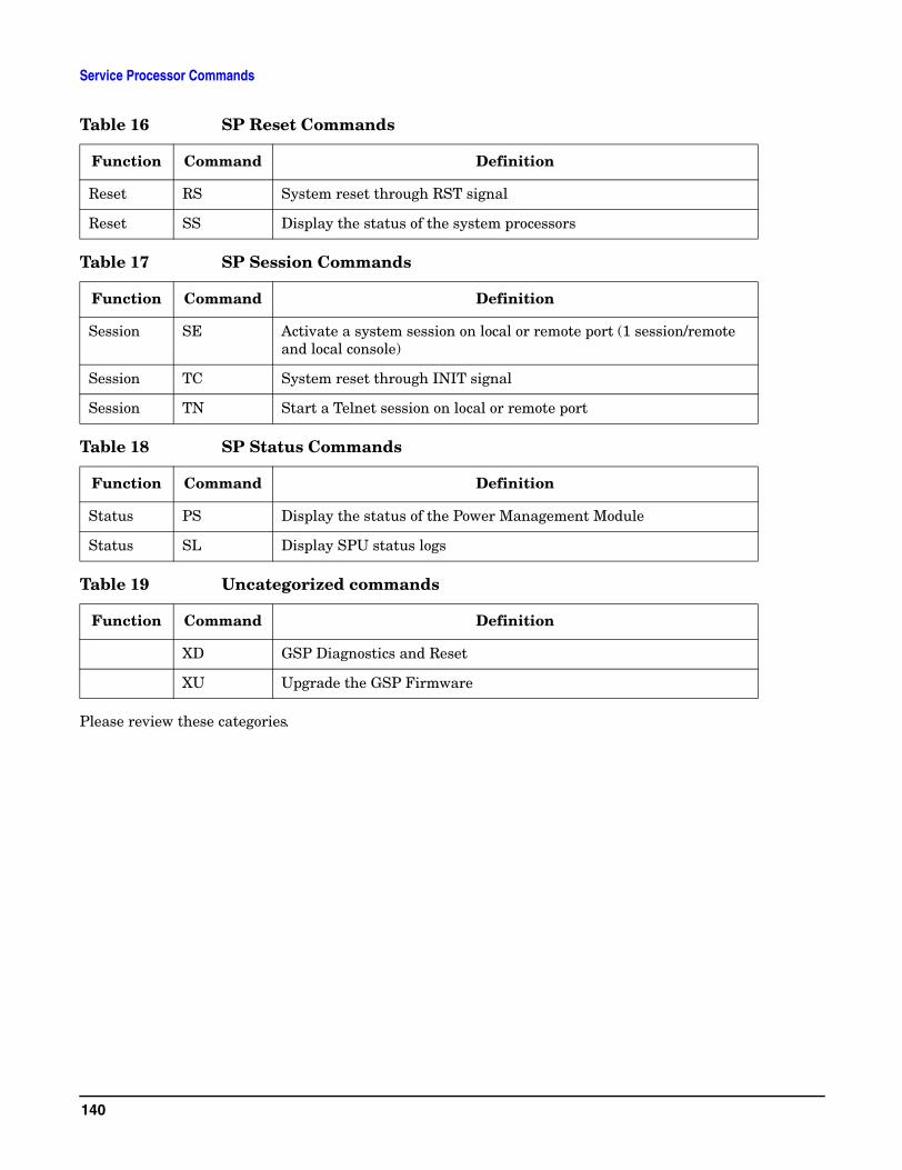
Service Processor Commands
Please review these categories.
Table 16 SP Reset Commands
Function Command Definition
Reset RS System reset through RST signal
Reset SS Display the status of the system processors
Table 17 SP Session Commands
Function Command Definition
Session SE Activate a system session on local or remote port (1 session/remote and local console)
Session TC System reset through INIT signal
Session TN Start a Telnet session on local or remote port
Table 18 SP Status Commands
Function Command Definition
Status PS Display the status of the Power Management Module
Status SL Display SPU status logs
Table 19 Uncategorized commands
Function Command Definition
XD GSP Diagnostics and Reset
XU Upgrade the GSP Firmware
140
Shutting Down the SPU
Shut down and power off the rp7400 computer system as follows:
NOTE Check with the System Administrator to ensure that a system backup has recently been performed prior to shutting down the system.
Step 1. Stop all active applications
Step 2. Perform a normal Operating System shut down. Be sure to inform all logged on users of the impending shutdown.
Step 3. After the Operating System has halted, set the Power switch to the standby (O) position.
Step 4. Remove power from the SPU by unplugging the power cords (up to 3 power cords) from the rear of the SPU.
NOTE The LEDs on the core I/O and on the power supplies will remain lit for several seconds after power is removed. Do not access any components until all LEDs are no longer lit.
Chapter 1

Shutting Down the SPUShutting Down the SPU
Chapter2
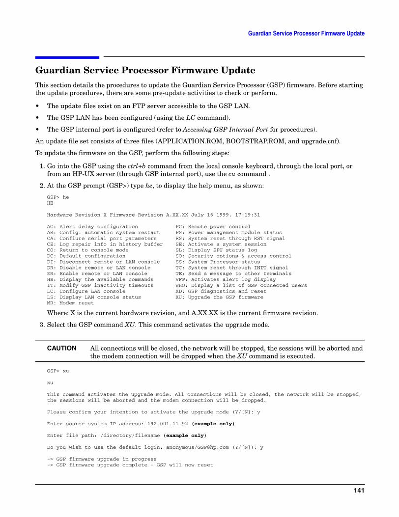
Guardian Service Processor Firmware Update
Guardian Service Processor Firmware UpdateThis section details the procedures to update the Guardian Service Processor (GSP) firmware. Before starting the update procedures, there are some pre-update activities to check or perform.
• The update files exist on an FTP server accessible to the GSP LAN.
• The GSP LAN has been configured (using the LC command).
• The GSP internal port is configured (refer to Accessing GSP Internal Port for procedures).
An update file set consists of three files (APPLICATION.ROM, BOOTSTRAP.ROM, and upgrade.cnf).
To update the firmware on the GSP, perform the following steps:
1. Go into the GSP using the ctrl+b command from the local console keyboard, through the local port, or from an HP-UX server (through GSP internal port), use the cu command .
2. At the GSP prompt (GSP>) type he, to display the help menu, as shown:
GSP> heHE
Hardware Revision X Firmware Revision A.XX.XX July 16 1999, 17:19:31
AC: Alert delay configuration PC: Remote power controlAR: Config. automatic system restart PS: Power management module statusCA: Confiure serial port parameters RS: System reset through RST signalCE: Log repair info in history buffer SE: Activate a system sessionCO: Return to console mode SL: Display SPU status logDC: Default configuration SO: Security options & access controlDI: Disconnect remote or LAN console SS: System Processor statusDR: Disable remote or LAN console TC: System reset through INIT signalER: Enable remote or LAN console TE: Send a message to other terminalsHE: Display the available commands VFP: Activates alert log displayIT: Modify GSP inactivity timeouts WHO: Display a list of GSP connected usersLC: Configure LAN console XD: GSP diagnostics and resetLS: Display LAN console status XU: Upgrade the GSP firmwareMR: Modem reset
Where: X is the current hardware revision, and A.XX.XX is the current firmware revision.
3. Select the GSP command XU. This command activates the upgrade mode.
CAUTION All connections will be closed, the network will be stopped, the sessions will be aborted and the modem connection will be dropped when the XU command is executed.
GSP> xu
xu
This command activates the upgrade mode. All connections will be closed, the network will be stopped, the sessions will be aborted and the modem connection will be dropped.
Please confirm your intention to activate the upgrade mode (Y/[N]: y
Enter source system IP address: 192.001.11.92 (example only)
Enter file path: /directory/filename (example only)
Do you wish to use the default login: anonymous/[email protected] (Y/[N]): y
-> GSP firmware upgrade in progress-> GSP firmware upgrade complete - GSP will now reset
141
Guardian Service Processor Firmware Update
NOTE If you are returned to the GSP prompt (GSP>) instead of the reset message, the update was not successful. This may be caused by incorrect information, or the LAN was not configured properly. Check the LAN parameters (using the LS command) and try again.
4. Use ctrl+b to re-login to GSP (or the cu command from the internal port).
5. Re-enter the GSP he command to verify the firmware revision number has changed to the version you have updated.
NOTE If you do the update from the GSP internal port, following the last message above, you need to exit the cu command and re-issue the cu command in order to continue using the GSP from the internal port.
Once the GSP has reset, you will need to reconnect all sessions that were aborted.
142
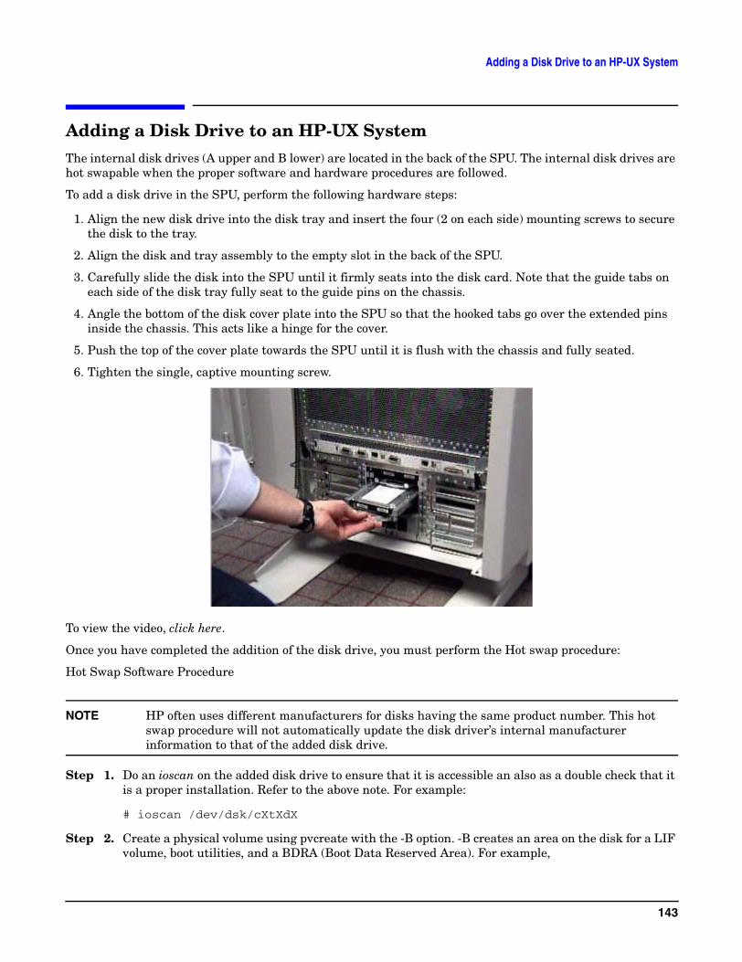
Adding a Disk Drive to an HP-UX System
Adding a Disk Drive to an HP-UX SystemThe internal disk drives (A upper and B lower) are located in the back of the SPU. The internal disk drives are hot swapable when the proper software and hardware procedures are followed.
To add a disk drive in the SPU, perform the following hardware steps:
1. Align the new disk drive into the disk tray and insert the four (2 on each side) mounting screws to secure the disk to the tray.
2. Align the disk and tray assembly to the empty slot in the back of the SPU.
3. Carefully slide the disk into the SPU until it firmly seats into the disk card. Note that the guide tabs on each side of the disk tray fully seat to the guide pins on the chassis.
4. Angle the bottom of the disk cover plate into the SPU so that the hooked tabs go over the extended pins inside the chassis. This acts like a hinge for the cover.
5. Push the top of the cover plate towards the SPU until it is flush with the chassis and fully seated.
6. Tighten the single, captive mounting screw.
To view the video, click here.
Once you have completed the addition of the disk drive, you must perform the Hot swap procedure:
Hot Swap Software Procedure
NOTE HP often uses different manufacturers for disks having the same product number. This hot swap procedure will not automatically update the disk driver’s internal manufacturer information to that of the added disk drive.
Step 1. Do an ioscan on the added disk drive to ensure that it is accessible an also as a double check that it is a proper installation. Refer to the above note. For example:
# ioscan /dev/dsk/cXtXdX
Step 2. Create a physical volume using pvcreate with the -B option. -B creates an area on the disk for a LIF volume, boot utilities, and a BDRA (Boot Data Reserved Area). For example,
143
Adding a Disk Drive to an HP-UX System
# pvcreate -B /dev/rdsk/cXtXdX
Step 3. Create a directory for the volume group using mkdir.
Step 4. Create a device file named group in the above directory with the mknod command.
Step 5. Create the root volume group specifying each physical volume to be included using vgcreate. For example:
vgcreate /dev/vgroot /dev/dsk/cXtXdX
Step 6. Use mkboot to place boot utilities in the boot area:
mkboot /dev/rdsk/cXtXdX
Step 7. Use mkboot -a to add an AUTO file in boot LIF area, for example:
mkboot -a ‘’hpux (52.3.0;0)/stand/vmunix’’ /dev/rdsk/cXtXdX
Step 8. Create the root logical volume. You must specify contiguous extents (-C y) with bad block relocation disabled (-r n). For example,
lvcreate -C y -r n root /dev/vgroot
Step 9. Extend the mirrors onto the disk you’ve added. For example:
lvextend -m 1 <LV name> /dev/vgroot/root /dev/dsk/cXtXdX
Step 10. Specify that logical volume be used as the root logical volume, for example:
lvln -r /dev/vgroot/root
At this point you will need to create a file system on the disk. Refer to your HP-UX system administration documentation.
Hot Swap Procedure for Unattached Physical Volumes
Follow these steps to replace a hot swap disk drive for unattached physical volumes.
NOTE HP often uses different manufacturers for disks having the same product number. This hot swap procedure will not automatically update the disk driver’s internal manufacturer information to that of the added disk drive.
Step 1. Do an ioscan on the replaced disk drive to ensure that it is accessible an also as a double check that it is a proper replacement. Refer to the above note. For example:
# ioscan /dev/dsk/c2t4d0
144
Adding a Disk Drive to an HP-UX System
Step 2. Create a physical volume using pvcreate with the -B option. -B creates an area on the disk for a LIF volume, boot utilities, and a BDRA (Boot Data Reserved Area). For example:
# pvcreate -B /dev/rdsk/cXtXdX
Step 3. Create a directory for the volume group using mkdir.
Step 4. Create a device file named group in the above directory with the mknod command.
Step 5. Create the root volume group specifying each physical volume to be included using vgcreate. For example,
# vgcreate /dev/vgroot /dev/dsk/cXtXdX
Step 6. Use mkboot to place boot utilities in the boot area:
# mkboot /dev/rdsk/cXtXdX
Step 7. Use mkboot -a to add an AUTO file in boot LIF area, for example:
# mkboot -a ‘’hpux (52.3.0;0)/stand/vmunix’’ /dev/rdsk/cXtXdX
Step 8. Create the root logical volume. You must specify contiguous extents (-C y) with bad block relocation disabled (-r n). For example,
# lvcreate -C y -r n root /dev/vgroot
Step 9. Attach the new disk drive to the active volume group with the vgchange command.
# vgchange -a y <volume group name>
For example:
# vgchange -a y /dev/vg00
Step 10. After running the mkboot command, do an lvlnboot -R to link the added disk drive into the boot data reserved area of all the physical volumes in the volume group.
# lvlnboot -R
Step 11. Create mirrors on the disk you’ve added. For example,
lvextend -m 1 <LV name> /dev/vgroot/root /dev/dsk/cXtXdX
Step 12. Synchronize the mirrors. This may take several minutes as it will have to copy all the data from the original copy of the data to the mirrored extents. The logical volume(s) are still accessible to users’ applications during this command.
#vgsync <VG name>
For example:
#vgsync /dev/vg00
At this point the system should be fully functional.
145

Adding a Disk Drive to an HP-UX System
146
Adding a Power Supply
Adding a Power SupplyBefore unpacking the new power supply, inspect the shipping carton for obvious damage. If damage to the shipping carton is observed, report it to the carrier immediately.
Carefully unpack the new power supply. Check it for damage. If no damage is observed, proceed with the instructions that follow. If damage is noticed, do not install the power supply. Get a replacement power supply.
WARNING Be careful lifting the power supply into the SPU, it weights approximately 7.88 Kg (17.5lbs.).
WARNING The AC power to the SPU does not have to be disconnected to add a power supply to the SPU. Also the power switch on the SPU does not have to be in the standby position to perform this task.
To add a power supply in the SPU, perform the following steps:
1. Be sure the power switch on the power supply is in the OFF position. (To view the video of the switch, click here.)
2. Remove the front bezel. (To view the video of the bezel, click here.)
3. Remove the EMI shield. (To view the video of the EMI shield, click here.)
4. Remove the power supply slot cover in the desired position, by loosening the two captive screws at the top edge of the cover, then pull it away from the SPU.
5. Align the power supply with the selected empty slot in the front of the SPU.
6. Slide the power supply into the SPU while holding the insertion/extractor lever out (horizontal).
7. Push the power supply into the SPU firmly until the insertion/extractor lever can hook under the extended tab on the SPU.
8. Push the insertion/extractor lever down, flush with the power supply. This firmly seats the power supply to the system board.
9. Tighten the two captive mounting screws.
10. Be sure the power cord associated with the power supply installed is connected at the back of the SPU.
11. Put the power switch, on the front of the power supply, in to the ON position.
NOTE The power OK LED should be on when the power switch is in the ON position, and there is a power cord plugged in.
147
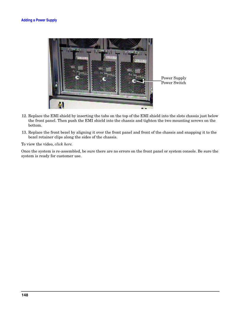
Adding a Power Supply
12. Replace the EMI shield by inserting the tabs on the top of the EMI shield into the slots chassis just below the front panel. Then push the EMI shield into the chassis and tighten the two mounting screws on the bottom.
13. Replace the front bezel by aligning it over the front panel and front of the chassis and snapping it to the bezel retainer clips along the sides of the chassis.
To view the video, click here.
Once the system is re-assembled, be sure there are no errors on the front panel or system console. Be sure the system is ready for customer use.
Power Supply Power Switch
148
Add-On Memory
Add-On MemoryFollow these procedures to add memory to an rp7400 server.
Memory Configuration Rules
rp7400 systems support up to 4 memory carriers (numbered 0, 1, 2, and 3), each with slots for 4 memory DIMM pairs (numbered 0a/b, 1a/b, 2a/b, and 3a/b). For the DIMMs to work, both DIMMs in a slot pair must be the same type (i.e., the same part number).
• Performance considerations. For best performance, install DIMMs evenly among the carriers, loading carriers 0, 1, 2, and 3 in sequence. For example, four 512MB memory DIMM pairs should be loaded into slot 0a/b on carrier 0, then slot 0a/b on carrier 1, and so on.
Although not a requirement for performance, the largest memory sizes should be installed first, making it more convenient if the memory DIMMs are re-sequenced at a later time.
• Cooling considerations. The following will help optimize air flow cooling within the system.
Always install memory carriers in the sequence 0, 1, 2, than 3. For example, if you have only two memory carriers, make sure they are installed as carrier 0 and carrier 1.
Install DIMMs into the carriers in the following slot order: 0a/b, 1a/b, 2a/b, 3a/b.
NOTE The most important rule is that DIMMs of the same type are distributed evenly amongst the carriers. If necessary, remove and re-sequence existing memory modules to balance the distribution; otherwise, a PDC error may occur.
Procedure Overview
1. Remove power from the system.2. Remove the front bezel.3. Extend the SPU out the back of the cabinet.4. Remove the back top cover5. Remove the back air baffle6. Remove the memory carrier.7. Install new memory DIMMs in the memory carrier.8. Reinstall the memory carrier.9. Replace the back air baffle
10. Replace the top cover.11. Slide the SPU back into the cabinet.12. Replace the front bezel.13. Power ON the SPU.14. Verify the installation.
149
Add-On Memory
Step 1. Remove Power From the System
CAUTION Before starting any shut down type procedures, be sure to check with the System Administrator or customer to ensure a system backup has been performed recently.
To shut down and power off the rp7400 computer system, perform the following steps.
a. Stop all active applications.
b. Perform a normal Operating System shut down, informing all logged on users of the impending shut down.
c. Once the Operating system has halted, put the power switch in the standby (0) position.
CAUTION With the power switch in the standby position, there is still power to the inside of the SPU.
d. Remove A.C. from the SPU by unplugging the power cords (up to 3) from the back of the SPU.
Step 2. Remove the Front Bezel
a. Grasp the front bezel on each side.
b. Pull the front bezel away from the cabinet.
Step 3. Extend the SPU out the Back of the Cabinet
CAUTION Be aware of the cables at the back of the SPU while moving the SPU in or out of the cabinet.
To extend the SPU out the back of the cabinet:
a. Remove the four (two on each side) retainer screws, holding the bezel flange to the cabinet vertical post.
b. Carefully extend the SPU out the front of the cabinet approximately 2 to 4 inches.
c. Loosen the six (three on each side) mounting screws holding the bezel brackets to the side of the SPU.
d. Lift the bezel bracket up and off the SPU chassis. Be sure that both left and right side brackets are removed.
e. Be sure the rear door is open and does not swing closed during the SPU movement. If necessary the rear door can be removed
f. Carefully extend the SPU out the back of the cabinet until the stops on the rails halt reward motion.
150
Add-On Memory
NOTE It is recommended that you pull the SPU from the back of the cabinet. This allows you to monitor the cable movement to avoid snags and tangles with other SPUs or cables.
The SPU should now be fully extended out the back of the cabinet.
WARNING Only extend one SPU at a time. Never attempt to extend more that one SPU for any reason.
Step 4. Remove the Back Top Cover
CAUTION Operating the system without the back top cover in place can make the SPU susceptible to EMI problems. Replace the back top cover before operating the system.
To remove a back top cover from the SPU:
a. Loosen the two captive screws along the back edge of the top cover.
b. Lift the back edge of the top cover up and away from the SPU
Step 5. Remove the Back Air Baffle
CAUTION Operating the system without the back air baffle will create air flow problems and possibly shorten the life of the internal components. Hewlett-Packard does not recommend the system be powered on with the air baffles removed. Also, operation of the system without the top cover and air baffle in place can make the system susceptible to EMI problems.
To remove the back air baffle from the:
a. Loosen the two captive mounting screws at the support bridge.
b. Grasp the air baffle along the extruded handle on the back edge of the air baffle and lift it out of the SPU.
Step 6. Remove the Memory Carrier
The memory carriers (up to four) are located along the back of the SPU.
CAUTION Be sure to have an anti-static pad or ESD compliant work place to rest the memory carrier on.
To remove the memory carrier from the SPU:
a. Grasp the insertion/extractor levers on the appropriate memory carrier and pull them up to disengage the memory carrier form the system board.
b. Carefully pull the memory carrier out of the SPU.
Step 7. Install the Memory DIMMs in the Memory Carrier
151

Add-On Memory
The memory DIMM resides in slots located on the memory carrier. The memory DIMMs are loaded in DIMM pairs.
Memory DIMMs are keyed and only install into a memory carrier one way. Memory DIMMs are only installed in matched (memory size) pairs. Be sure the memory DIMM being installed is matched to the appropriate DIMM in the pair slot.
To add a memory DIMM in the memory carrier:
a. Align the memory DIMM over the correct memory carrier slot. Be sure the extractor levers are in the open position (angled out from the memory slot).
b. Firmly and evenly (pressure on both ends of the memory DIMM) press the memory DIMM into the memory carrier slot until the memory DIMM fully seats and the extractor levers are up against the outside edges of the memory DIMM.
c. Pick up the memory carrier and visually check to see that all memory DIMMs are seated fully. No memory DIMM card edge should be higher than the others. This indicates that a memory DIMM is not fully seated into the memory carrier slot. Press firmly on the raised edge to seat the memory DIMM into its’ socket.
d. Replace the memory DIMM hold down bracket.
Step 8. Replace the Memory Carrier
The memory carriers (up to four) are located along the back of the SPU. Memory carriers are installed from slot 0 through slot 3 (slot 0 is the right most slot facing the back of the SPU).
To replace the memory carrier in the SPU:
a. While holding the memory carrier by the extended insertion/extractor levers, align the memory carrier with the appropriate slot card guides on the system board.
b. Carefully lower the memory carrier into the card guides, until the insertion/extractor levers hook under the card guide edges.
c. Press the insertion/extractor levers down until the memory carrier firmly seats into the system board. The insertion/extractor levers should be parallel with the memory carrier edge.
Step 9. Replace the Back Air Baffle
CAUTION Operating the SPU without the back air baffle will create air flow problems and possibly shorten the life of the internal components. Hewlett-Packard does not recommend the SPU be powered on with the air baffles removed. Also, operation of the SPU without the top cover and air baffle in place can make the SPU susceptible to EMI problems.
To replace the back air baffle in the SPU:
a. Angle the back edge of the air baffle onto the support bridge flange, then lower the air baffle over the CPU cooling towers (up to four).
CAUTION Be sure all CPU cooling tower tops are centered in the support brackets. The support brackets have enough play in them to allow proper alignment.
b. Be sure the air baffle sits flush into the SPU.
152
Add-On Memory
c. Tighten the two captive screws at the support bridge.
Step 10. Replace the Back Top Cover
To replace the back top cover in the SPU:
a. Angle the back edge of the top cover into the support bridge. Be sure the tabs at the back edge of the top cover insert into the slots on the support bridge.
b. Lower the top cover onto the SPU. Firmly press the top cover down onto the SPU, making sure the outer edges of the top cover are over the top edges of the chassis.
c. Tighten the two captive screws.
Step 11. Insert the SPU Back into the Cabinet
CAUTION Be aware of the cables at the back of the SPU while moving the SPU in or out of the cabinet.
To insert the SPU into the cabinet from the back:
a. Press the rail slide locks (one on each side) to release the rail locks while gently pushing the SPU forward.
b. Carefully insert the SPU all the way into the cabinet until the front of the SPU sticks out approximately 2 to 4 inches.
NOTE It is recommended that you push the SPU from the back of the cabinet. This allows you to monitor the cable movement to avoid snags and tangles with other SPUs or cables.
c. Align the left and right bezel bracket key slots over the three bracket screws on each side of the SPU.
d. Slide the bezel brackets down and tighten the six (three on each side) bracket screws.
e. Carefully push the SPU back into the cabinet until the bezel brackets contact the cabinet vertical rails.
f. Insert the four (two on each side, T25) SPU retainer screws, located just below and above bezel snap tabs.
Check all cables to be sure none have been loosened during the previous procedure. Close or replace the rear door.
153
Add-On Memory
Step 12. Replace the Front Bezel
To replace the front bezel, perform the following steps:
a. Align the front bezel over the front of the SPU.
b. Press the front bezel onto the cabinet until it snaps into place.
Step 13. Power the System On
CAUTION Before applying A.C. power to an rp7400 computer, be sure all covers and cooling fans are properly installed. Failure to perform this check could result in decreased computer component life and reliability.
a. Be sure all connected peripherals are on, with no errors or faults indicated.
b. Be sure the SPU power switch is in the standby (0) position.
CAUTION When the power cords are connected to the SPU, there will be power present inside the SPU chassis, even with the power switch in the standby position.
c. Carefully insert the A.C. power cords (3) into the line filter receptacles at the back of the SPU.
NOTE Be sure to plug all three power cords into the back of the SPU. Also be sure the cabinet PDU is plugged into an appropriate wall outlet.
d. Put the power switch in the on (|) position. At this time you will hear the cooling fans coming up to speed and being synchronized. This creates a high pitched squeak for a few seconds. The fans should drop to normal speed within a few seconds. If not check the front panel or console for fault indications.
e. Check all front panel LEDs for normal indications, with no warnings ar faults indicated.
The SPU should take a few minutes to perform all selftests and initialization routines. At the end of this you should be able to launch the operating system or initiate other software routines.
Step 14. Verify the Installation
Issue the ME command in the boot console handler to verify the system recognizes the new memory configuration.
154
Add I/O Cards
Add I/O CardsThe rp7400 server has 12 expansion I/O slots accessible through side panels on the rear of the SPU chassis. Six slots are located on each of the two sides.
Slots 3 through 12 are “TwinTurbo” slots supporting 66MHz, 64-bit I/O cards. Slots 1 and 2 are “Turbo” slots supporting cards with lower speed and bandwidth. If higher speed cards are installed in slots 1 or 2, they will function but their performance will be reduced. Similarly, slower cards can be installed in slots 3 through 12, but their performance will not be improved.
There are two configuration rules to consider:
• Load the slowest cards in slots 1 and 2.
• When possible, balance the total number of PCI cards between the two sides. E.g., when adding four PCI cards, install two on the right (slots 1 through 6) and two on the left (slots 7 through 12).
CAUTION If you are installing the A3783A 10/100Base-TX LAN card, do not connect any type of MAU transceiver to the AUI connector while the system is powered up. Doing so will cause power to be shut off to the I/O slot and will generate a High Priority Machine Check (HPMC) error.
If you are going to connect a MAU transceiver to this card’s AUI connector, make sure the system is powered down first. When the system is powered back on, this connection will then not generate an error condition.
Refer to the instructions shipped with this LAN card for further information.
Procedure Overview
1. Remove power from the system
2. Remove the front bezel
3. Extend the SPU out the back of the system
4. Remove the PCI slot cover
5. Insert the new PCI card
6. Replace the PCI slot cover
7. Slide the SPU back into the cabinet
8. Replace the front bezel
9. Power the system back on
10. Verify the procedure
155
Add I/O Cards
Step 1. Remove Power from the System.
CAUTION Before starting any shut down type procedures, be sure to check with the System Administrator or customer to ensure a system backup has been performed recently.
To shut down and power off the N Class computer system, perform the following steps.
a. Stop all active applications.
b. Perform a normal Operating System shut down, informing all logged on users of the impending shut down.
c. Put the power switch in the standby position.
CAUTION With the power switch in the standby position, there is still power to the inside of the SPU.
d. Remove A.C. from the SPU by unplugging the power cords (up to 3) from the back of the SPU.
Step 2. Remove the Front Bezel
a. Grasp the front bezel on each side.
b. Pull the front bezel away from the cabinet.
Step 3. Extend the SPU out the Back of the System
CAUTION Be aware of the cables at the back of the SPU while moving the SPU in or out of the cabinet.
To extend the SPU out the back of the cabinet:
a. Remove the four (two on each side) retainer screws, holding the bezel flange to the cabinet vertical post.
b. Carefully extend the SPU out the front of the cabinet approximately 2 to 4 inches.
c. Loosen the six (three on each side) mounting screws holding the bezel brackets to the side of the SPU.
d. Lift the bezel bracket up and off the SPU chassis. Be sure that both left and right side brackets are removed.
e. Be sure the rear door is open and does not swing closed during the SPU movement. If necessary the rear door can be removed
f. Carefully extend the SPU out the back of the cabinet until the stops on the rails halt rearward motion.
NOTE It is recommended that you pull the SPU from the back of the cabinet. This allows you to monitor the cable movement to avoid snags and tangles with other SPUs or cables.
156
Add I/O Cards
The SPU should now be fully extended out the back of the cabinet.
WARNING Only extend one SPU at a time. Never attempt to extend more that one SPU for any reason.
Step 4. Remove the PCI Cover Plate
NOTE Steps 4 through 8 apply to the six PCI card slots on either side of the SPU. As viewed from the rear of the cabinet, slots 1 through 6 are on the left side. The lowermost slot in the array is slot 1. Slots 7 through 12 are on the right side, with slot 7 being the lowermost slot in the array.
a. Loosen the two captive screws at the end of the I/O card slot cover.
b. Swing the cover away and off of the SPU.
Step 5. Insert the I/O Card Into the Slot
NOTE The PCI card slots have separators which protect against touching adjacent cards when plugging in PCI cards. The separators also have tabs which facilitate removing the cards.
a. Remove the metal slot cover, if present, at the rear of the SPU.
b. Align the PCI card with the appropriate slot.
c. Insert the PCI card into the card cage, between the separator/extractor cards.
d. Press firmly on the PCI card to be sure it is fully seated.
Step 6. Replace the PCI Cover Plate
a. Swing the I/O slot cover closed.
b. Tighten the two captive screws at the end of the slot cover.
NOTE The PCI card slots have separators which protect against touching adjacent cards when plugging in PCI cards. The separators also have tabs which facilitate removing the cards.
Step 7. Insert the SPU Back Into the Cabinet
CAUTION Be aware of the cables at the back of the SPU while moving the SPU in or out of the cabinet.
To insert the SPU into the cabinet from the back:
a. Carefully insert the SPU all the way into the cabinet until the front of the SPU sticks out the front approximately 2 to 4 inches.
157
Add I/O Cards
b. Align the left and right bezel bracket key slots over the three bracket screws on each side of the SPU.
c. Slide the bezel brackets down and tighten the six (three on each side) bracket screws.
d. Carefully push the SPU back into the cabinet until the bezel brackets contact the cabinet vertical rails.
e. Insert the four (two on each side, T25) SPU retainer screws, located just below and above bezel snap tabs.
Check all cables to be sure none have been loosened during the previous procedure. Close or replace the rear door.
Step 8. Replace the Front Bezel
To replace the front bezel, perform the following steps:
a. Align the front bezel over the front of the SPU.
b. Press the front bezel onto the cabinet until it snaps into place.
Step 9. Power the System On
CAUTION Before applying A.C. power to an rp7400 computer, be sure all covers and cooling fans are properly installed. Failure to perform this check could result in decreased computer component life and reliability.
a. Be sure all connected peripherals are on, with no errors or faults indicated.
b. Be sure the SPU power switch is in the standby (0) position.
CAUTION When the power cords are connected to the SPU, there will be power present inside the SPU chassis, even with the power switch in the standby position.
c. Carefully insert the A.C. power cords (3) into the line filter receptacles at the back of the SPU.
NOTE Be sure to plug all three power cords into the back of the SPU. Also be sure the cabinet PDU is plugged into an appropriate wall outlet.
d. Put the power switch in the on (|) position. At this time you will hear the cooling fans coming up to speed and being synchronized. This creates a high pitched squeak for a few seconds. The fans should drop to normal speed within a few seconds. If not check the front panel or console for fault indications.
e. Check all front panel LEDs for normal indications, with no warnings ar faults indicated.
The SPU should take a few minutes to perform all selftests and initialization routines. At the end of this you should be able to launch the operating system or initiate other software routines.
Step 10. Verify the Procedure
Run the ioscan utility to ensure the system recognizes the I/O card.
158
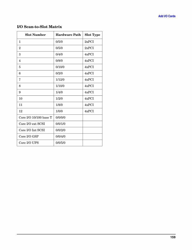
Add I/O Cards
I/O Scan-to-Slot Matrix
Slot Number Hardware Path Slot Type
1 0/5/0 2xPCI
2 0/5/0 2xPCI
3 0/4/0 4xPCI
4 0/8/0 4xPCI
5 0/10/0 4xPCI
6 0/2/0 4xPCI
7 1/12/0 4xPCI
8 1/10/0 4xPCI
9 1/4/0 4xPCI
10 1/2/0 4xPCI
11 1/8/0 4xPCI
12 1/0/0 4xPCI
Core I/O 10/100 base T 0/0/0/0
Core I/O ext SCSI 0/0/1/0
Core I/O Int SCSI 0/0/2/0
Core I/O GSP 0/0/4/0
Core I/O UPS 0/0/5/0
159

Add I/O Cards
160