rov technical report - mate rov competition... · the rov’s main systems are: power and e...
TRANSCRIPT

The Remotely Operated Vehicle, ARChaos, was constructed with the purpose of competing in the 4th Annual ROV Design and Building Competition for High School and College Students. The vehicle will perform a simulated mission to Europa, one of the six known orbiting moons of Jupiter, and conduct a series of tasks including: re-establishing a communications link, retrieving data probes, collect a sample of red fluid, and measure the temperature of a venting fluid. The ROV’s main systems are: power and electrical (electrical schematics, power source, console wiring & ROV wiring, tether, safety), propulsion systems (thrusters & power requirements) based on Innovation First system, navigation system, housing/case (frame, ballast), visual systems (camera & power requirements), and additional systems/sensors (temperature sensors and digital readout, liquid extraction system, object recovery & payload system). We performed integrated systems testing once all individual systems were tested and the ROV was assembled. This report also covers photographs, electrical schematic, challenges faced, troubleshooting techniques, lessons learned, future improvements, as well as a description of careers, organizations, and technologies that support the mission themes. Acknowledgements are included at the end of the report.
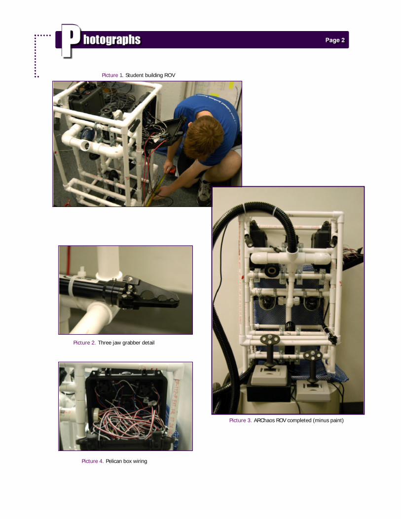
Picture 1. Student building ROV
Picture 2. Three jaw grabber detail
Picture 3. ARChaos ROV completed (minus paint)
Picture 4. Pelican box wiring
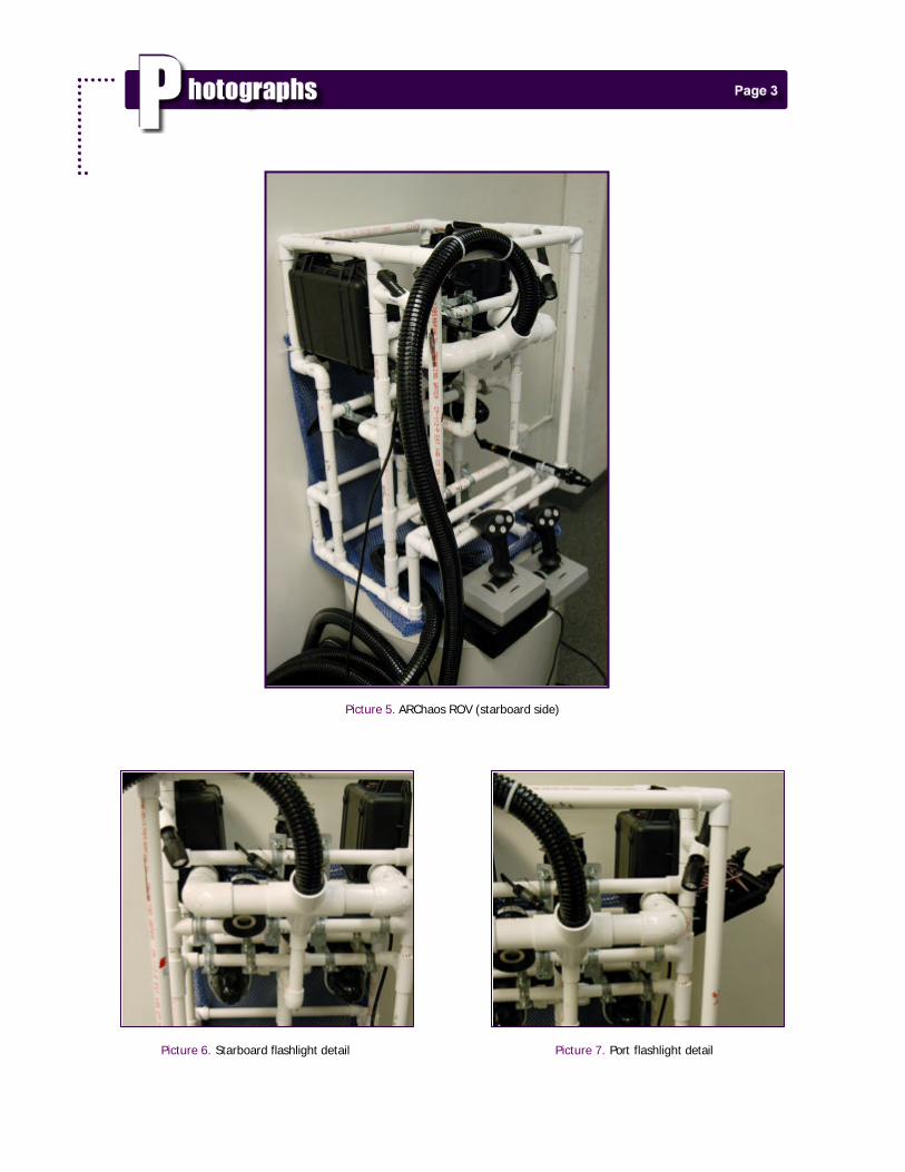
Picture 5. ARChaos ROV (starboard side) Picture 6. Starboard flashlight detail Picture 7. Port flashlight detail
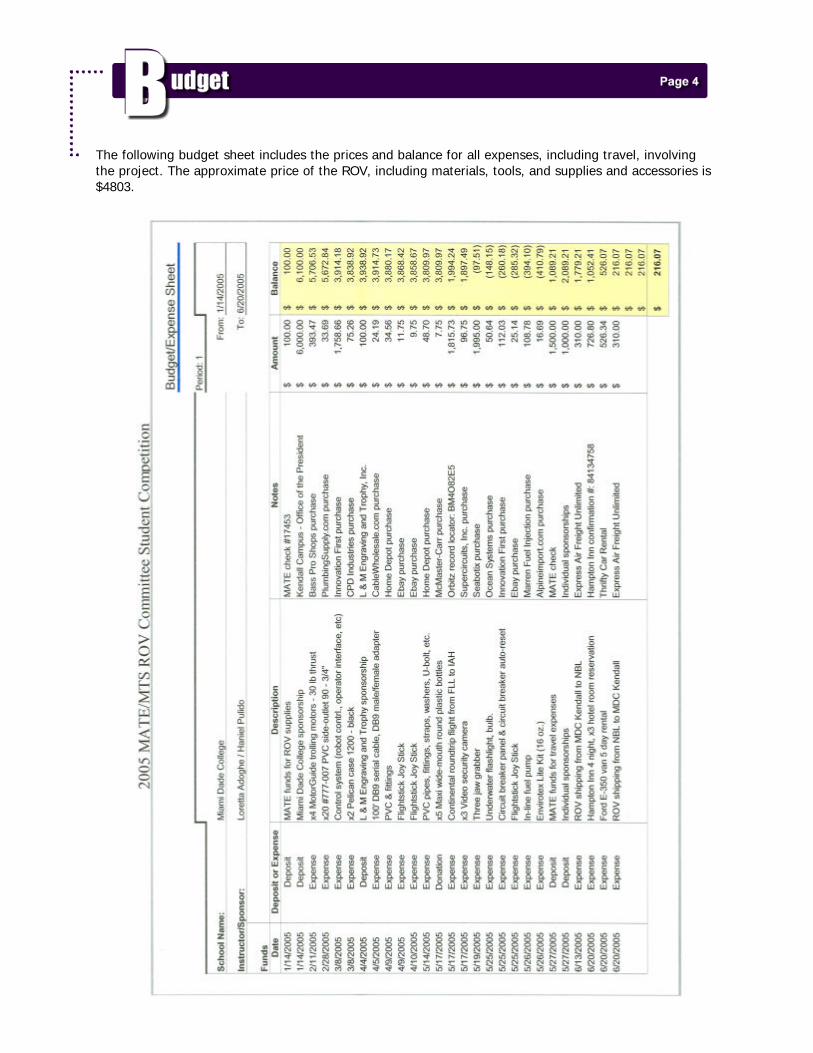
The following budget sheet includes the prices and balance for all expenses, including travel, involving the project. The approximate price of the ROV, including materials, tools, and supplies and accessories is $4803.

Each of the major components/systems of the ROV vehicle are subdivided as follows:
Power and Electrical
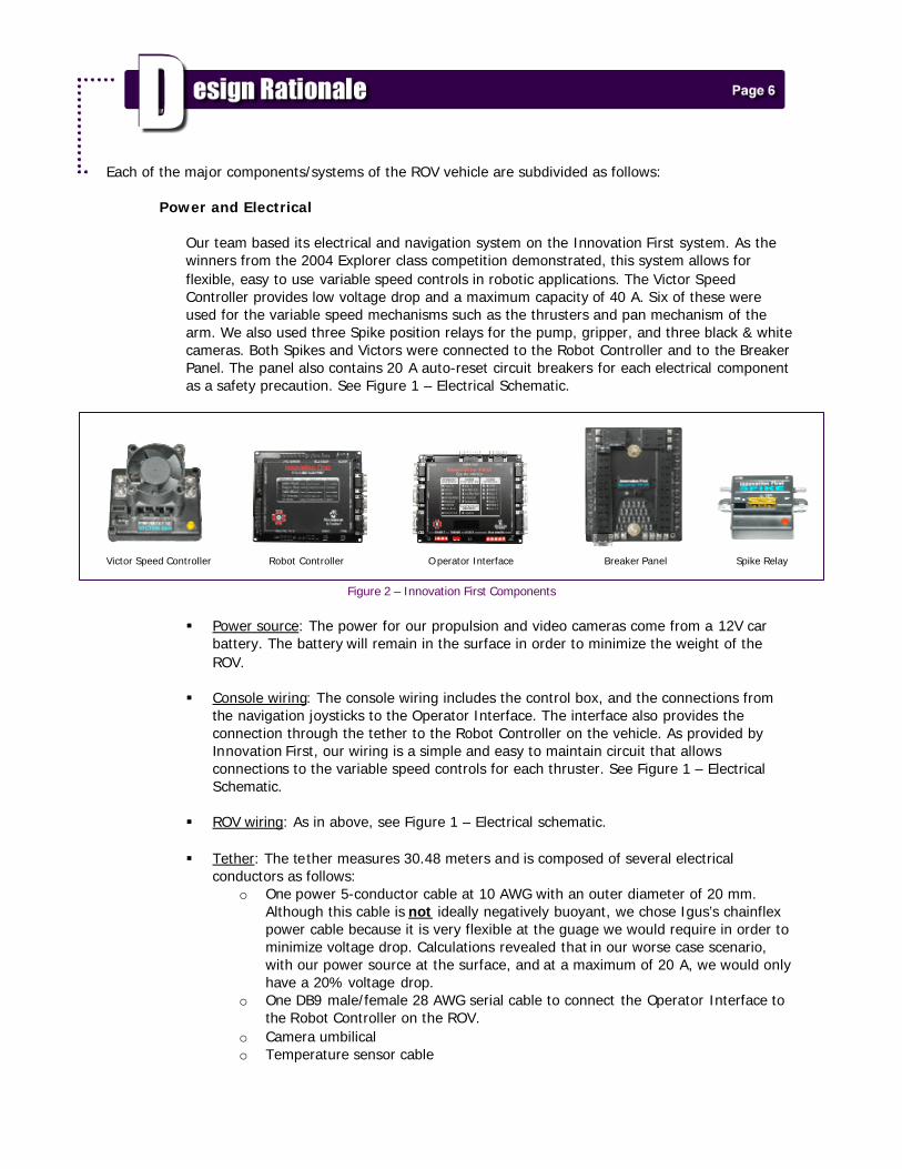
Our team based its electrical and navigation system on the Innovation First system. As the winners from the 2004 Explorer class competition demonstrated, this system allows for flexible, easy to use variable speed controls in robotic applications. The Victor Speed Controller provides low voltage drop and a maximum capacity of 40 A. Six of these were used for the variable speed mechanisms such as the thrusters and pan mechanism of the arm. We also used three Spike position relays for the pump, gripper, and three black & white cameras. Both Spikes and Victors were connected to the Robot Controller and to the Breaker Panel. The panel also contains 20 A auto-reset circuit breakers for each electrical component as a safety precaution. See Figure 1 – Electrical Schematic.
Victor Speed Controller Robot Controller O perator Interface Breaker Panel Spike Relay
Figure 2 – Innovation First Components
§ Power source: The power for our propulsion and video cameras come from a 12V car battery. The battery will remain in the surface in order to minimize the weight of the ROV.
§ Console wiring: The console wiring includes the control box, and the connections from
the navigation joysticks to the Operator Interface. The interface also provides the connection through the tether to the Robot Controller on the vehicle. As provided by Innovation First, our wiring is a simple and easy to maintain circuit that allows connections to the variable speed controls for each thruster. See Figure 1 – Electrical Schematic.
§ ROV wiring: As in above, see Figure 1 – Electrical schematic. § Tether: The tether measures 30.48 meters and is composed of several electrical
conductors as follows: o One power 5-conductor cable at 10 AWG with an outer diameter of 20 mm.
Although this cable is not ideally negatively buoyant, we chose Igus’s chainflex power cable because it is very flexible at the guage we would require in order to minimize voltage drop. Calculations revealed that in our worse case scenario, with our power source at the surface, and at a maximum of 20 A, we would only have a 20% voltage drop.
o One DB9 male/female 28 AWG serial cable to connect the Operator Interface to the Robot Controller on the ROV.
o Camera umbilical o Temperature sensor cable

§ Safety: The Breaker Panel mounted on the ROV provides and distributes power (12 V) to the electrical components. The panel’s connections work by simply connecting our devices along with 20 A & 30 A auto-resetting circuit breakers. The Breaker Panel is also "smart". The unit will monitor each breaker that is installed and knows which and when each breaker has tripped or is tripping. This information is vital during robot evaluation and troubleshooting.
Propulsion Systems § Thrusters & power requirements: As we researched parts and materials for the ROV, we
found pictures and examples of other organizations and teams using trolling motors as their main propulsion system. After much deliberation and having agreed that such a technique would be successful, we decided on the smallest available motor we could find: the MotorGuide Freshwater Transom Mount Trolling Motor. We purchased four motors to be mounted on the vehicle as follows:
o One on aft-port and the other on aft-starboard to allow for tight turns and smooth propulsion forward and backward
o The third and fourth motors are positioned facing each other at the center of the ROV to allow for vertical movement and balance (longitudinal and transverse trim). This positioning allows for maximum efficiency for each motor when the vehicle is surfacing or diving.
Other factors that lead towards the purchase of these motors include: each motor provides approximately 13.61 Kg of thrust, as well as a waterproof enclosure minus the shaft. We also used four 500 gph Rule bilge pumps to provide strafing navigation of the vehicle. Two pumps each were installed on the port and starboard sides of the ROV and they were modified by cutting and removing the impeller. We then installed a propeller to complete the thruster.
Navigation Systems
We will navigate the ROV using three Flightstick Pro joysticks. One will control port/starboard strafing and surface/dive action. Another will control port/starboard rotation and backward/forward movement. The final joystick will control the pan action of the robotic arm and port/starboard rotation of the ROV using bilge pumps. Figure 3 – Joysticks
Housing/Case § Frame: Since we were limited to common household tools, we decided to make the ROV
frame of PVC schedule 40 pipes (1.9 cm outer diameter) because it provides flexibility in achieving the modeled design using different connectors (90º, 45º elbows, T’s, etc.). The dimensions are 51 cm (length) x 49 cm (width) x 86 cm (height).
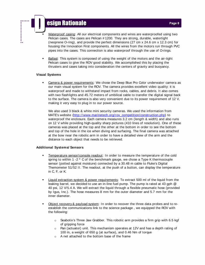
§ Waterproof casing: All our electrical components and wires are waterproofed using two Pelican cases. The cases are Pelican #1200. They are strong, durable, watertight (neoprene O-ring), and provide the perfect dimensions (27 cm x 24.6 cm x 12.3 cm) for housing the Innovation First components. All the wires from the motors run through PVC pipes into the cases. This connection is also waterproof through the use of O-rings.
§ Ballast: This system is composed of using the weight of the motors and the air-tight
Pelican cases to give the ROV good stability. We accomplished this by placing the thrusters and cases taking into consideration the centers of gravity and buoyancy.
Visual Systems § Camera & power requirements: We chose the Deep Blue Pro Color underwater camera as
our main visual system for the ROV. The camera provides excellent video quality; it is waterproof and made to withstand impact from rocks, cables, and debris. It also comes with two flashlights and 45.72 meters of umbilical cable to transfer the digital signal back to the surface. The camera is also very convenient due to its power requirement of 12 V, making it very easy to plug in to our power source. We also used 3 black & white mini security cameras. We used the information from MATE’s website (http://www.marinetech.org/rov_competition/construction.php) to waterproof the enclosure. Each camera measures 3.2 cm (length & width) and also runs on 12 V while providing high-quality sharp pictures (410 lines of resolution). One of these cameras was placed at the top and the other at the bottom in order to see the bottom and top of the hole in the ice when diving and surfacing. The final camera was attached at the bow near the robotic arm in order to have a detailed view of the arm and the distance to each object that needs to be retrieved.
Additional Systems/Sensors § Temperature sensor/console readout: In order to measure the temperature of the cold
spring to within 1 -2 º C of the benchmark gauge, we chose a Type K thermocouple sensor (potted against moisture) connected by a 30.48 m cable to Fluke’s Digital Themometer 51/52 II. The readout, at the push of a button, can display the temperature in C, F, or K.
§ Liquid extraction system & power requirements: To extract 500 ml of the liquid from the
leaking barrel, we decided to use an in-line fuel pump. The pump is rated at 43 gph @ 40 psi, 12 V/5.4 A. We will extract the liquid through a flexible pneumatic hose (provided by Igus, Inc.). The hose measures 8 mm for the outer diameter and 5.7 mm for the inner diameter.
§ Object recovery & payload system: In order to recover the three data probes and to re-
establish the communications link to the science package , we equipped the ROV with the following:
o Seabotix’s Three Jaw Grabber. This robotic arm provides a firm grip with 6.5 kgf
of gripping force o Pan (actuator) unit. This mechanism operates at 12V and has a depth rating of
100 m, a weight of 650 g (at surface), and 0.46 Nm of torque o A net attached to the bottom base of the frame
One of the first challenges we encountered were time issues with regards to the acquisition of funds from sponsors and construction materials. Although some of these problems were beyond our control, we tried to expedite the process by following up with our contacts and continued maintaining good communication with the respective individuals from each organization. Another challenge that was present throughout the duration of the project involved dealing with the dynamics of working in a group. Personal, communication, and/or meeting attendance issues were present. Fortunately, we were not delayed as much as we could have been due to the way each stage of the project was organized. We have a total of five members including our overall group leader. We assigned the responsibilities of each system to individual members: one acting as the head person for that system, and another as a backup. As a result, if one or more people were absent during the construction of the ROV, a backup person for any particular system would be available to attend to any issues or problems, especially during systems integration and testing. The biggest technical challenges in the project were in the initial choice of the propulsion system (size of thrusters) and towards the end, trimming and balancing the ROV appropriately. Once we decided on the MotorGuide trolling motors, we had to figure out a way of installing them to the ROV frame and waterproofing the motor shaft. By taking into consideration the centers of gravity and buoyancy as well as the size restrictions, we designed the frame of the vehicle around the motors. We designed the ROV using Discreet’s gmax and attached the shaft of the thrusters to the PVC with adapters (with O-rings) found at the local hardware/home improvement store. After much deliberation, we also agreed to install the vertical thrusters facing each other in order to maximize thruster efficiency and to allow for a more vertical frame design which would be easier to balance, trim, and navigate through the hole in the ice. The trim and balance of the ROV were also affected by the buoyancy of the two pelican boxes. We, therefore, positioned the boxes at the top so that they would counter the centered weight of the thrusters while at the same time allowing for extra room to add more floats if needed.

One problem we experienced involved the Deep Blue Pro Color underwater camera. The camera comes with 2 flashlights attached to the bottom (see Figure 4). This default configuration poses a problem when we approach solid surfaces. The light from the flashlight bounces off at such a small angle of reflection that the visual image becomes overexposed. To correct this, we tested different configurations through trial and error with the camera and flashlight. Taking into consideration the height of the ROV (86 cm), we chose the angle of incidence to be ~75° from the normal. This creates an identical angle of reflection bouncing off in the opposite direction and thus solving the problem (see Figure 5). Figure 4 – Default Flashlight Configuration Figure 5 – Corrected Flashlight Configuration
(not drawn to scale) We also used The Innovation First Dashboard Viewer to test and troubleshoot all of the electronic parts. The Dashboard Viewer is a free program designed to work with the In novation First Control System. The software provides enhanced robot feedback from the Robot Controller and also allows you to customize most of the labels to match the ROV’s functions. We connected all the components as we would on the ROV. The Robot Controller and joysticks were connected to the Operator Interface; the interface was then connected to the computer with a serial cable. This allowed us to test all the functions of the joysticks (forward/ reverse, buttons) as well as the variable speed controls.
Pictures 8-10. Students testing electrical components with Dashboard Viewer
Participating on this competition for the second time, our team learned valuable lessons including: § Research all materials and parts early and thoroughly. § Begin construction before the end of December and make better use of working parts from last
year’s ROV. § Manage our time better and keep up to date with the schedule we created at the beginning of
the year. § Visualize and focus on the tasks of the mission. Spend less time dealing with personal and
communication issues that usually occur when working in a group such as arguing about decisions that were discussed and made in prior meetings.
§ Keep the design and components simple. Minimize problems by creating a detailed and well
thought model (using modeling software such as CAD or gmax) and following through from model to reality.
§ Improvising on the fly, especially when we were trying to waterproof the motors and all the PVC
pipes that were connected to them.

For future competitions, it will be essential to commence the search for sponsors and funds at least one month earlier in order to compensate for any delays. Also, depending on the specifications of next year’s competition, we would like to make a more maneuverable ROV, reduce the size of the frame, and reduce the diameter and weight of our tether. In order to accomplish this, we will first need to research and purchase smaller thrusters or custom build our own. We would also like to have access to more versatile and powerful tools to fabricate parts that are either too expensive to buy or do not currently exist. Next year we will reserve MDC’s metal/wood shop months in advance so that we may be trained in the use of these sophisticated tools and how to apply them towards construction of future ROV’s. Finally, we would further need to emphasize the need to “keep it simple”, begin designing and working sooner on the actual system(s) and further explore all the possibilities for parts including: thrusters, frame, and accessories. As a mean to achieve this, all the information, including parts lists, description of challenges, procedures, will be documented in a notebook along with this technical report for the next competition.
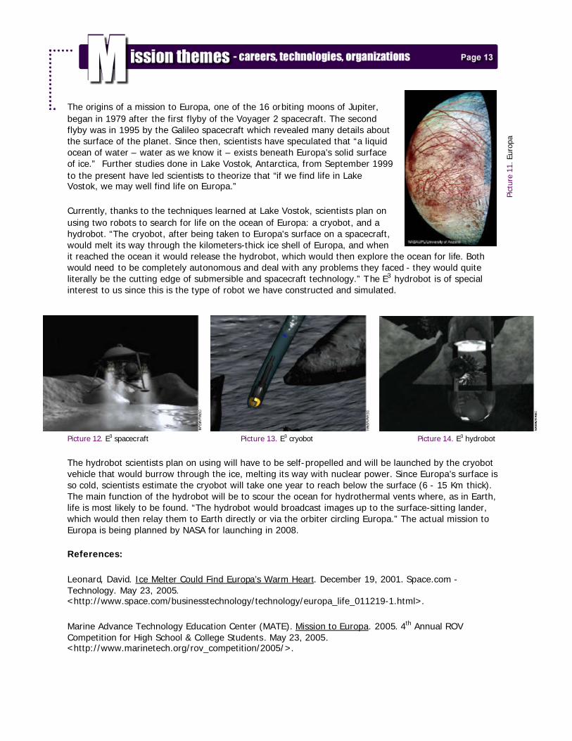
The origins of a mission to Europa, one of the 16 orbiting moons of Jupiter, began in 1979 after the first flyby of the Voyager 2 spacecraft. The second flyby was in 1995 by the Galileo spacecraft which revealed many details about the surface of the planet. Since then, scientists have speculated that “a liquid ocean of water – water as we know it – exists beneath Europa’s solid surface of ice.” Further studies done in Lake Vostok, Antarctica, from September 1999 to the present have led scientists to theorize that “if we find life in Lake Vostok, we may well find life on Europa.”
Currently, thanks to the techniques learned at Lake Vostok, scientists plan on using two robots to search for life on the ocean of Europa: a cryobot, and a hydrobot. “The cryobot, after being taken to Europa's surface on a spacecraft, would melt its way through the kilometers-thick ice shell of Europa, and when it reached the ocean it would release the hydrobot, which would then explore the ocean for life. Both would need to be completely autonomous and deal with any problems they faced - they would quite literally be the cutting edge of submersible and spacecraft technology.” The E3 hydrobot is of special interest to us since this is the type of robot we have constructed and simulated.
Picture 12. E3 spacecraft Picture 13. E3 cryobot Picture 14. E3 hydrobot
The hydrobot scientists plan on using will have to be self-propelled and will be launched by the cryobot vehicle that would burrow through the ice, melting its way with nuclear power. Since Europa’s surface is so cold, scientists estimate the cryobot will take one year to reach below the surface (6 - 15 Km thick). The main function of the hydrobot will be to scour the ocean for hydrothermal vents where, as in Earth, life is most likely to be found. “The hydrobot would broadcast images up to the surface-sitting lander, which would then relay them to Earth directly or via the orbiter circling Europa.” The actual mission to Europa is being planned by NASA for launching in 2008.
References:
Leonard, David. Ice Melter Could Find Europa’s Warm Heart. December 19, 2001. Space.com - Technology. May 23, 2005. <http://www.space.com/businesstechnology/technology/europa_life_011219-1.html>.
Marine Advance Technology Education Center (MATE). Mission to Europa. 2005. 4th Annual ROV Competition for High School & College Students. May 23, 2005. <http://www.marinetech.org/rov_competition/2005/>.
Pict
ure
11. E
urop
a
We would like to thank our sponsors, Miami Dade College, Igus, Inc., Bilmor With Advertising Specialties, Inc., L & M Engraving and Trophy, Inc., and all the dedicated staff at each organization for their time and financial contributions to the ROV project: Miami Dade College § Loretta Adoghe, Program Director & mentor § Haniel Pulido Jr., Instructional Technologist & mentor § Dr. Alan Berkey, Associate Dean, School of Natural & Social Sciences § Sonia Pershin, Secretary, School of Natural & Social Sciences § Office of the President, Kendall Campus
• Dr. Wasim Shomar, Kendall Campus President
Igus, Inc. § Jonathan Falcon § Courtney Toomey
Bilmor With Advertising Specialties, Inc. § Robin De Souza
L & M Engraving and Trophy, Inc. § Sandy Liebavitz