routers ip to mpls to cesr - cse, iit bombaycs641/notes/lec15-routers-gumaste.pdf · 1997 622mb/s...
TRANSCRIPT

ROUTERS
IP TO MPLS TO CESR

OUTLINE
Background
What is a router?
Why do we need faster routers?
Why are they hard to build?
Architectures and techniques
The evolution of router architecture.
IP address lookup.
Packet buffering.
Switching.
The Future
2

WHAT IS ROUTING FORWARDING?
3
R3
A
B
C
R1
R2
R4 D
E
FR5
R5F
R3E
R3D
Next HopDestination

WHAT IS ROUTING?
4
R3
A
B
C
R1
R2
R4 D
E
FR5
R5F
R3E
R3D
Next HopDestination
16 3241
Data
Options (if any)
Destination Address
Source Address
Header ChecksumProtocolTTL
Fragment OffsetFlagsFragment ID
Total Packet LengthT.ServiceHLenVer
20
byte
s

WHAT IS ROUTING?
5
A
B
C
R1
R2
R3
R4 D
E
FR5
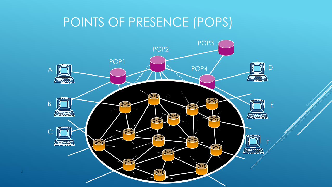
POINTS OF PRESENCE (POPS)
6
A
B
C
POP1
POP3POP2
POP4 D
E
F
POP5
POP6POP7
POP8
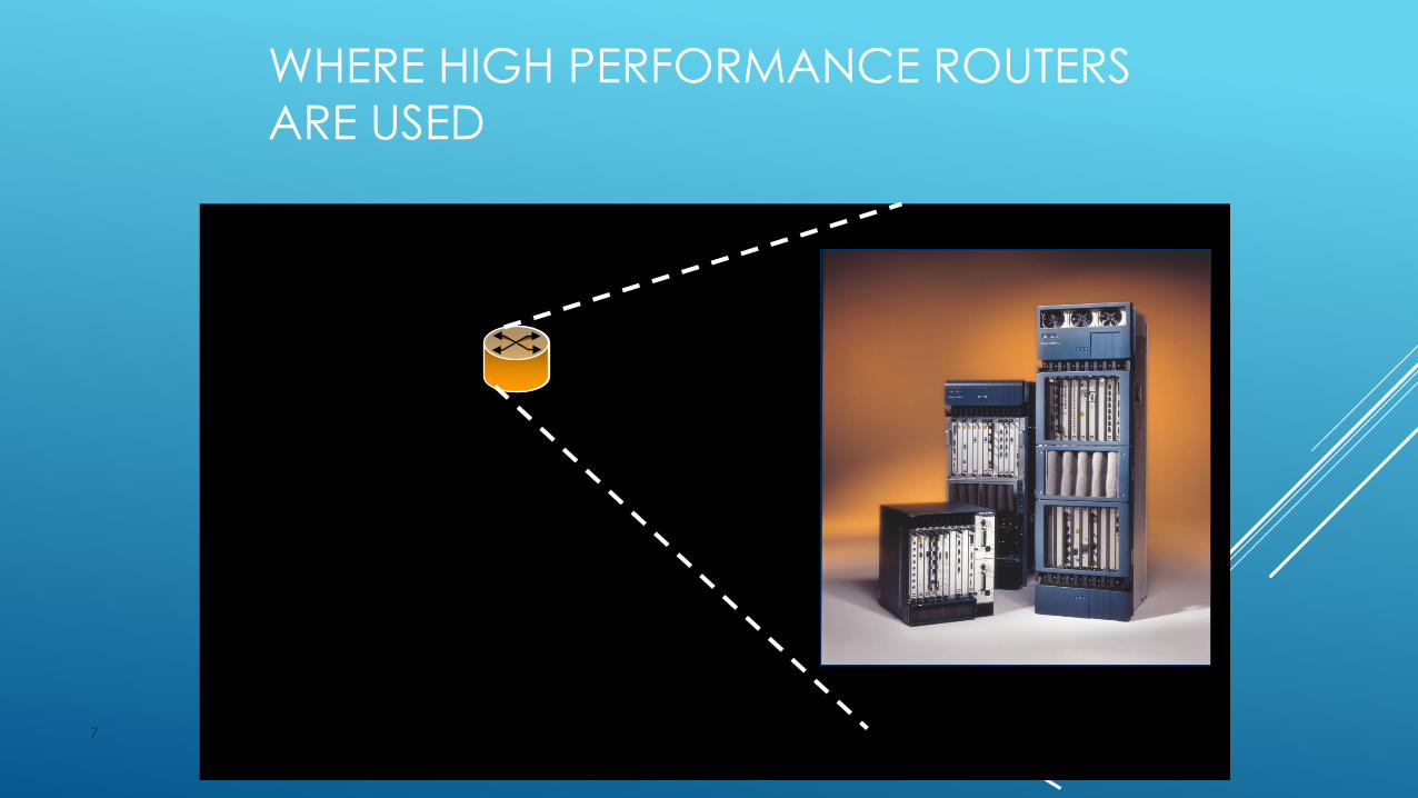
WHERE HIGH PERFORMANCE ROUTERS
ARE USED
7
R10R11
R4
R13
R9
R5
R2R1 R6
R3 R7
R12
R16
R15
R14
R8
(2.5 Gb/s)
(2.5 Gb/s)(2.5 Gb/s)
(2.5 Gb/s)

WHAT A ROUTER LOOKS LIKE
8
Cisco GSR 12416 Juniper M160
6ft
19”
2ft
Capacity: 160Gb/sPower: 4.2kW
3ft
2.5ft
19”
Capacity: 80Gb/sPower: 2.6kW
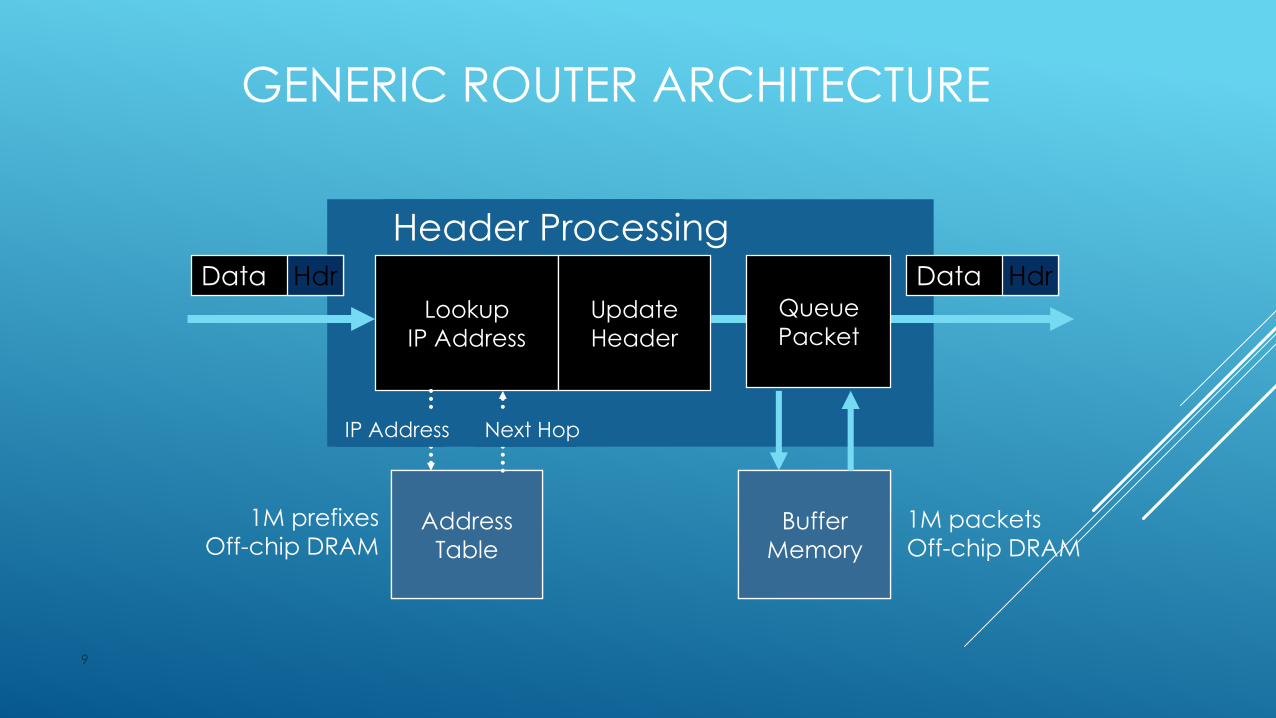
GENERIC ROUTER ARCHITECTURE
9
Lookup
IP Address
Update
Header
Header Processing
Data Hdr Data Hdr
1M prefixes
Off-chip DRAMAddress
Table
Address
Table
IP Address Next Hop
Queue
Packet
Buffer
Memory
Buffer
Memory
1M packets
Off-chip DRAM
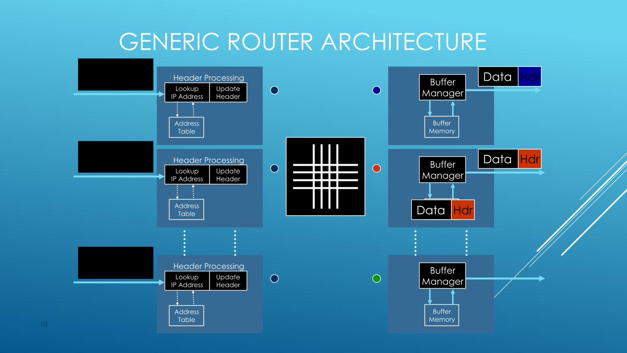
GENERIC ROUTER ARCHITECTURE
10
Lookup
IP Address
Update
Header
Header Processing
Address
Table
Address
Table
Lookup
IP Address
Update
Header
Header Processing
Address
Table
Address
Table
Lookup
IP Address
Update
Header
Header Processing
Address
Table
Address
Table
Data Hdr
Data Hdr
Data Hdr
BufferManager
Buffer
Memory
Buffer
Memory
BufferManager
Buffer
Memory
Buffer
Memory
BufferManager
Buffer
Memory
Buffer
Memory
Data Hdr
Data Hdr
Data Hdr
WHY DO WE NEED FASTER ROUTERS?
1. To prevent routers becoming the bottleneck in the Internet.
2. To increase POP capacity, and to reduce cost, size and
power.
11
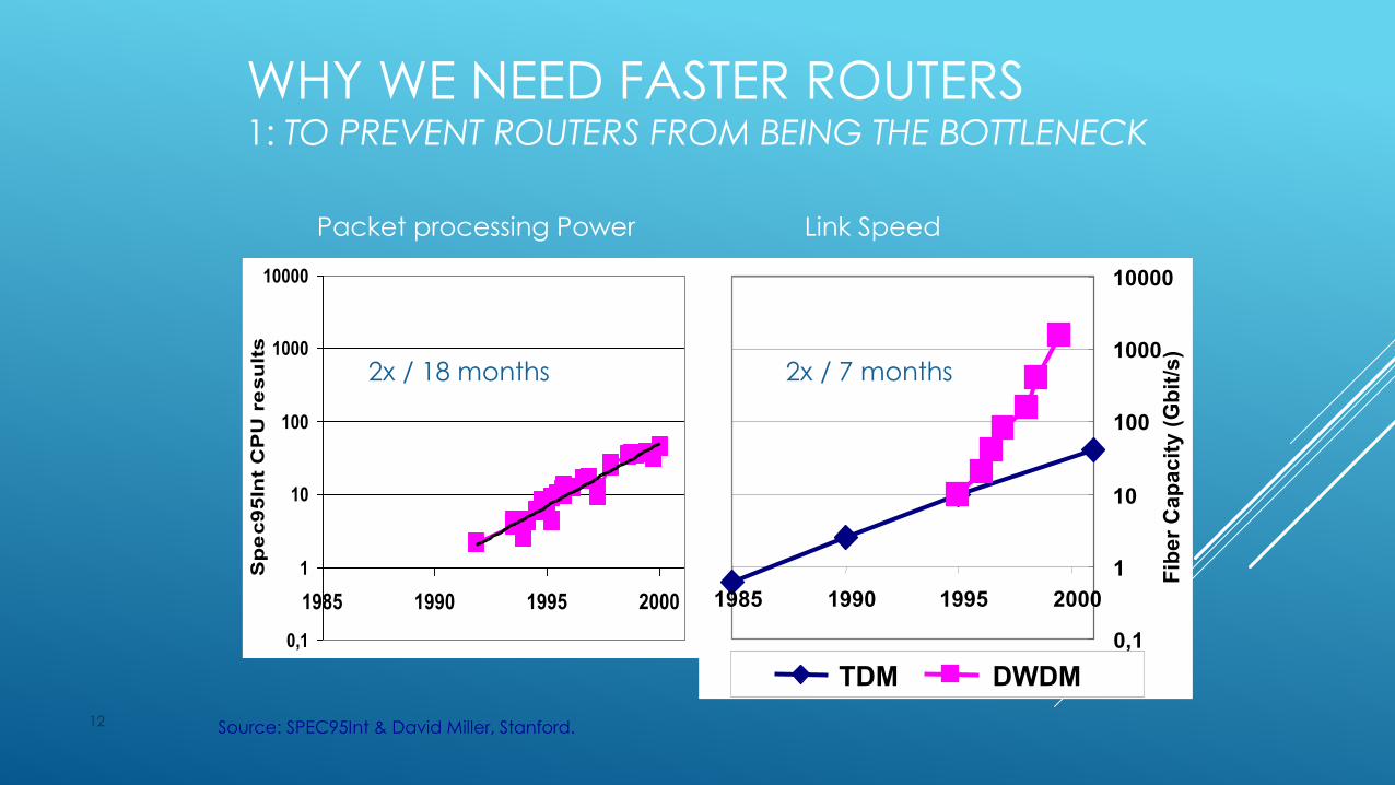
WHY WE NEED FASTER ROUTERS 1: TO PREVENT ROUTERS FROM BEING THE BOTTLENECK
12
0,1
1
10
100
1000
10000
1985 1990 1995 2000
Sp
ec95In
t C
PU
re
su
lts
0,1
1
10
100
1000
10000
1985 1990 1995 2000
Fib
er
Cap
ac
ity (
Gb
it/s
)
TDM DWDM
Packet processing Power Link Speed
2x / 18 months 2x / 7 months
Source: SPEC95Int & David Miller, Stanford.

WHY WE NEED FASTER ROUTERS 2: TO REDUCE COST, POWER & COMPLEXITY OF POPS
13
POP with smaller routersPOP with large routers
Ports: Price >$100k, Power > 400W. It is common for 50-60% of ports to be for interconnection.
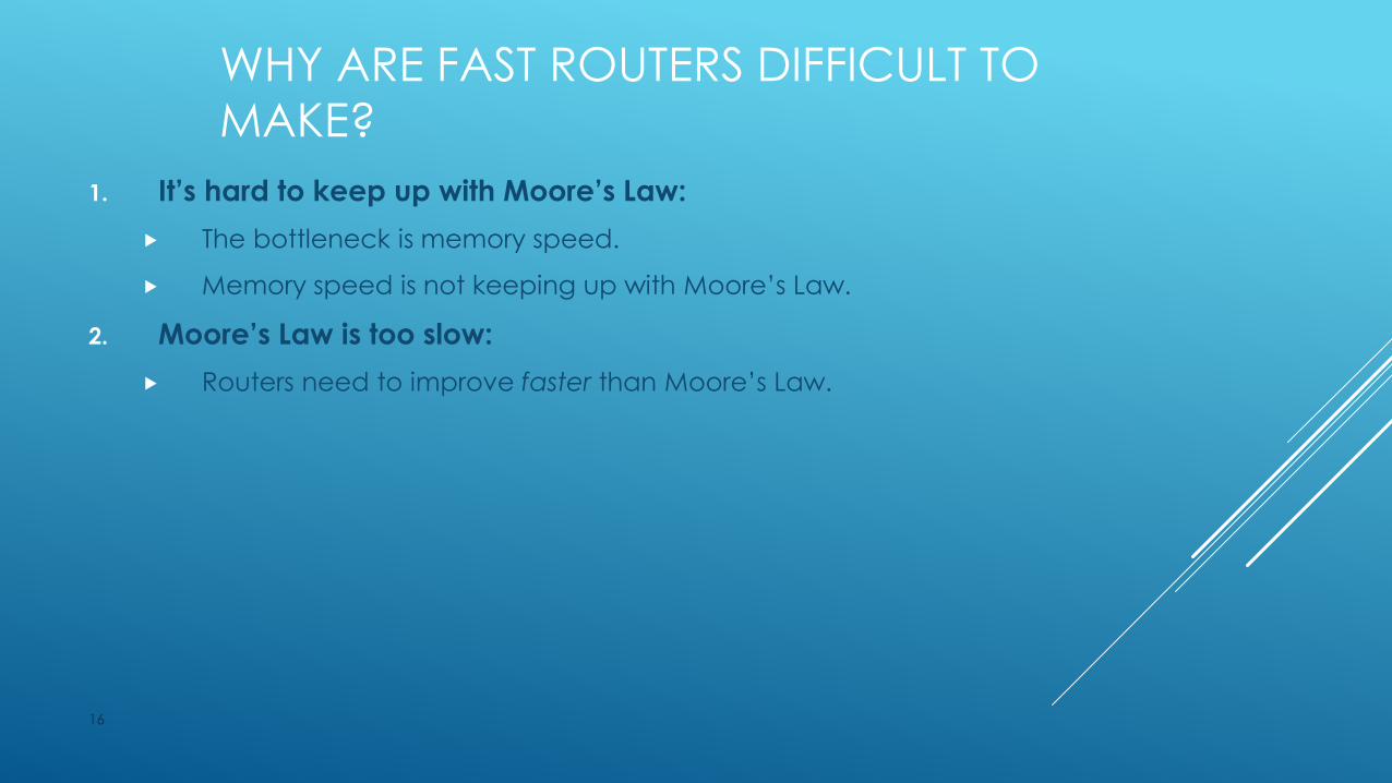
WHY ARE FAST ROUTERS DIFFICULT TO
MAKE?
1. It’s hard to keep up with Moore’s Law:
The bottleneck is memory speed.
Memory speed is not keeping up with Moore’s Law.
14
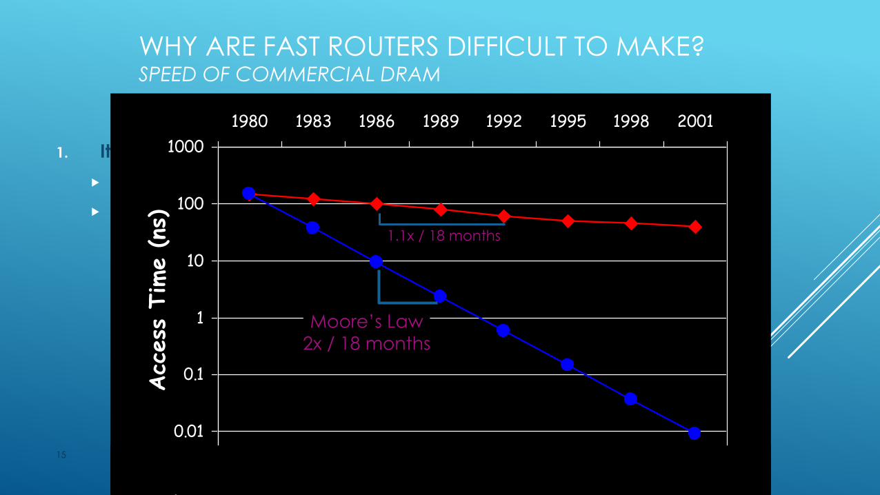
WHY ARE FAST ROUTERS DIFFICULT TO MAKE?SPEED OF COMMERCIAL DRAM
1. It’s hard to keep up with Moore’s Law:
The bottleneck is memory speed.
Memory speed is not keeping up with Moore’s Law.
15
0.001
0.01
0.1
1
10
100
1000
1980 1983 1986 1989 1992 1995 1998 2001
Acc
ess
Tim
e (ns
)
Moore’s Law
2x / 18 months
1.1x / 18 months
WHY ARE FAST ROUTERS DIFFICULT TO
MAKE?
1. It’s hard to keep up with Moore’s Law:
The bottleneck is memory speed.
Memory speed is not keeping up with Moore’s Law.
2. Moore’s Law is too slow:
Routers need to improve faster than Moore’s Law.
16
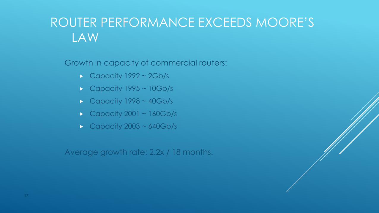
ROUTER PERFORMANCE EXCEEDS MOORE’S
LAW
Growth in capacity of commercial routers:
Capacity 1992 ~ 2Gb/s
Capacity 1995 ~ 10Gb/s
Capacity 1998 ~ 40Gb/s
Capacity 2001 ~ 160Gb/s
Capacity 2003 ~ 640Gb/s
Average growth rate: 2.2x / 18 months.
17
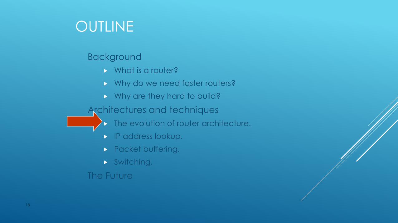
OUTLINE
Background
What is a router?
Why do we need faster routers?
Why are they hard to build?
Architectures and techniques
The evolution of router architecture.
IP address lookup.
Packet buffering.
Switching.
The Future
18

19
RouteTable
CPUBuffer
Memory
LineInterface
MAC
LineInterface
MAC
LineInterface
MAC
Typically <0.5Gb/s aggregate capacity
First Generation Routers
Shared Backplane
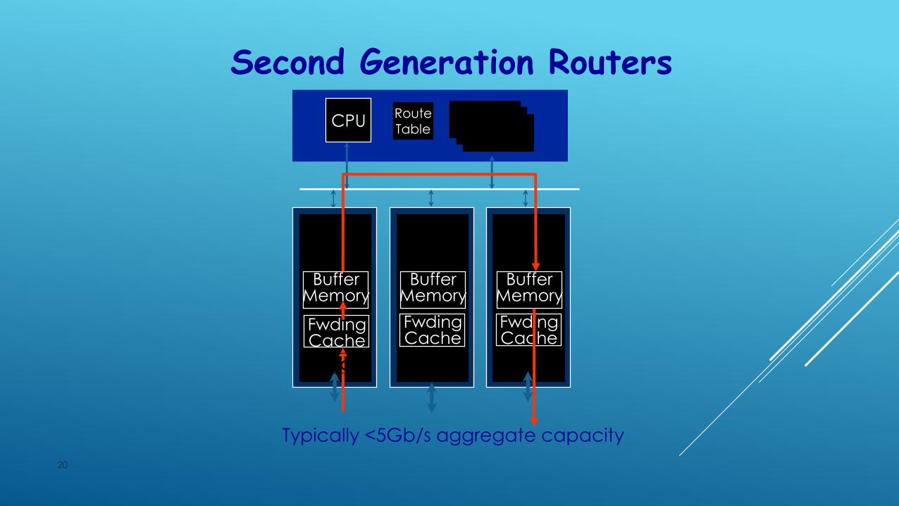
20
Second Generation RoutersRouteTable
CPU
LineCard
BufferMemory
LineCard
MAC
BufferMemory
LineCard
MAC
BufferMemory
FwdingCache
FwdingCache
FwdingCache
MAC
BufferMemory
Typically <5Gb/s aggregate capacity
21
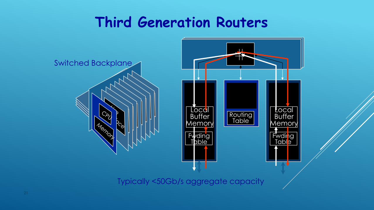
Third Generation Routers
LineCard
MAC
LocalBuffer
Memory
CPUCard
LineCard
MAC
LocalBuffer
Memory
Switched Backplane
FwdingTable
RoutingTable
FwdingTable
Typically <50Gb/s aggregate capacity
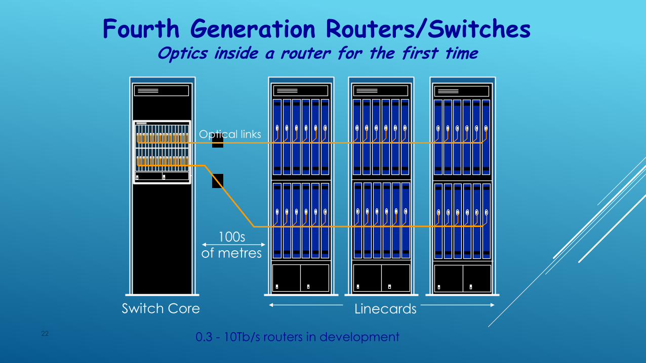
22
Fourth Generation Routers/SwitchesOptics inside a router for the first time
Switch Core Linecards
Optical links
100s
of metres
0.3 - 10Tb/s routers in development

OUTLINE
Background
What is a router?
Why do we need faster routers?
Why are they hard to build?
Architectures and techniques
The evolution of router architecture.
IP address lookup.
Packet buffering.
Switching.
The Future
23

GENERIC ROUTER ARCHITECTURE
24
Lookup
IP Address
Update
Header
Header Processing
Address
Table
Address
Table
Lookup
IP Address
Update
Header
Header Processing
Address
Table
Address
Table
Lookup
IP Address
Update
Header
Header Processing
Address
Table
Address
Table
BufferManager
Buffer
Memory
Buffer
Memory
BufferManager
Buffer
Memory
Buffer
Memory
BufferManager
Buffer
Memory
Buffer
Memory
Lookup
IP Address
Address
Table
Address
Table
Lookup
IP Address
Address
Table
Address
Table
Lookup
IP Address
Address
Table
Address
Table

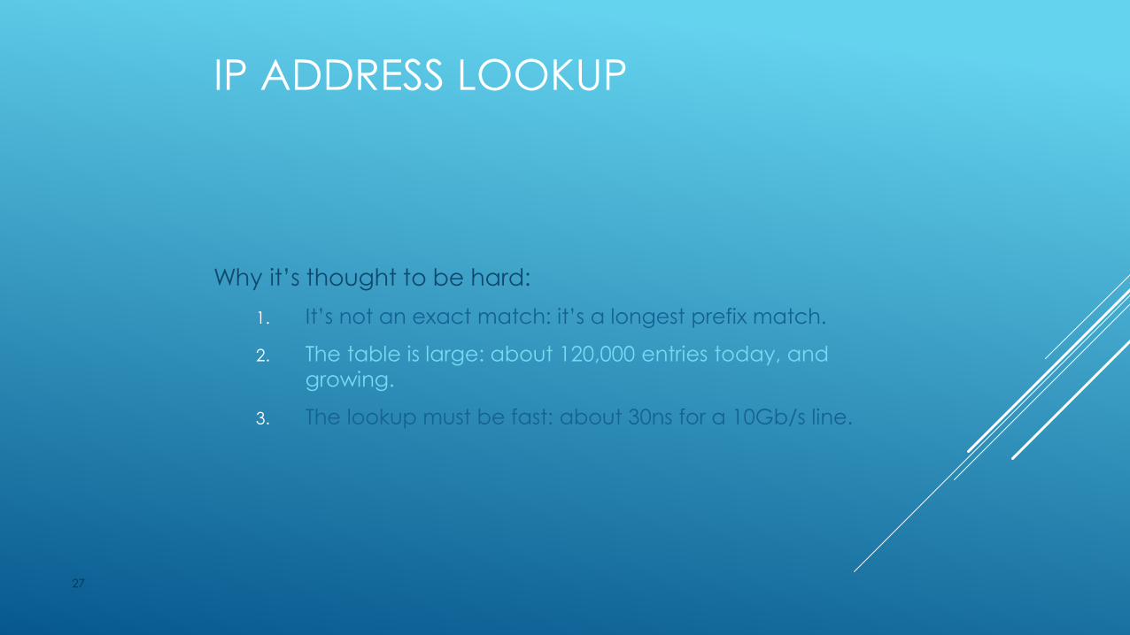
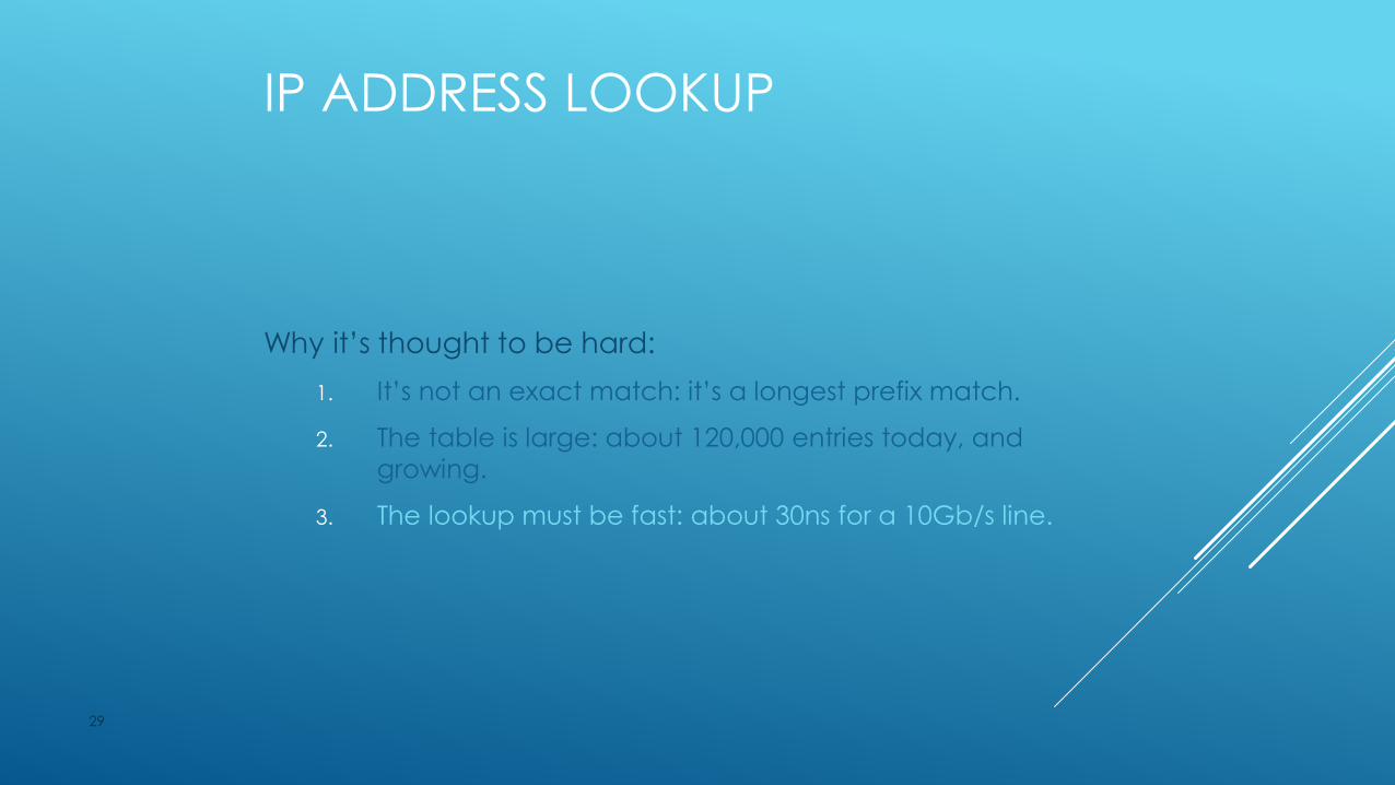
IP ADDRESS LOOKUP
Why it’s thought to be hard:
1. It’s not an exact match: it’s a longest prefix match.
2. The table is large: about 120,000 entries today, and
growing.
3. The lookup must be fast: about 30ns for a 10Gb/s line.
25
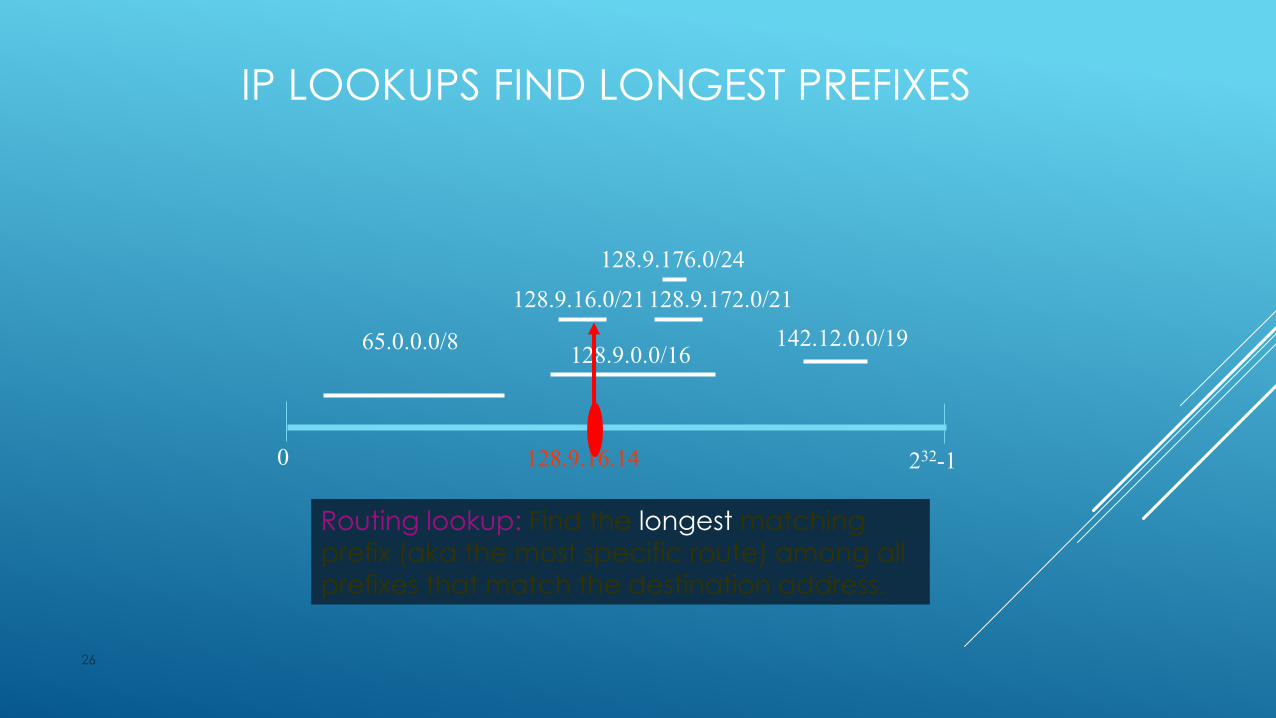
IP LOOKUPS FIND LONGEST PREFIXES
26
128.9.16.0/21 128.9.172.0/21
128.9.176.0/24
0 232-1
128.9.0.0/16142.12.0.0/1965.0.0.0/8
128.9.16.14
Routing lookup: Find the longest matching
prefix (aka the most specific route) among all
prefixes that match the destination address.
IP ADDRESS LOOKUP
Why it’s thought to be hard:
1. It’s not an exact match: it’s a longest prefix match.
2. The table is large: about 120,000 entries today, and
growing.
3. The lookup must be fast: about 30ns for a 10Gb/s line.
27

ADDRESS TABLES ARE LARGE
28
0
20000
40000
60000
80000
100000
120000
140000
Aug-87 May-90 Jan-93 Oct-95 Jul-98 Apr-01 Jan-04
Num
ber
of p
refixes
Source: Geoff Huston, Oct 2001
IP ADDRESS LOOKUP
Why it’s thought to be hard:
1. It’s not an exact match: it’s a longest prefix match.
2. The table is large: about 120,000 entries today, and
growing.
3. The lookup must be fast: about 30ns for a 10Gb/s line.
29
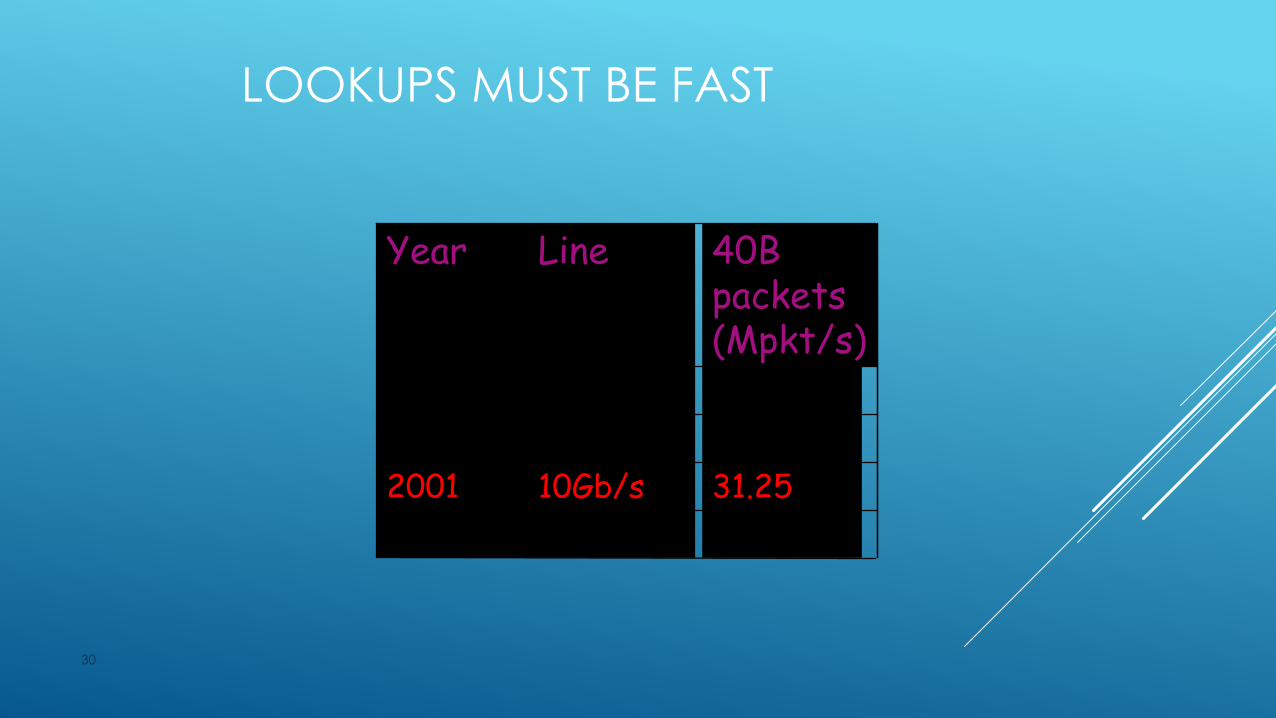
LOOKUPS MUST BE FAST
30
12540Gb/s2003
31.2510Gb/s2001
7.812.5Gb/s1999
1.94622Mb/s1997
40B packets (Mpkt/s)
LineYear
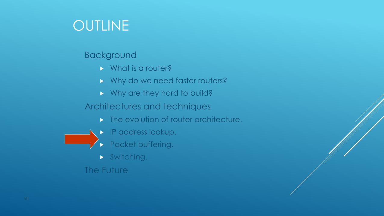
OUTLINE
Background
What is a router?
Why do we need faster routers?
Why are they hard to build?
Architectures and techniques
The evolution of router architecture.
IP address lookup.
Packet buffering.
Switching.
The Future
31

GENERIC ROUTER ARCHITECTURE
32
Lookup
IP Address
Update
Header
Header Processing
Address
Table
Address
Table
Lookup
IP Address
Update
Header
Header Processing
Address
Table
Address
Table
Lookup
IP Address
Update
Header
Header Processing
Address
Table
Address
Table
QueuePacket
Buffer
Memory
Buffer
Memory
QueuePacket
Buffer
Memory
Buffer
Memory
QueuePacket
Buffer
Memory
Buffer
Memory
BufferManager
Buffer
Memory
Buffer
Memory
BufferManager
Buffer
Memory
Buffer
Memory
BufferManager
Buffer
Memory
Buffer
Memory
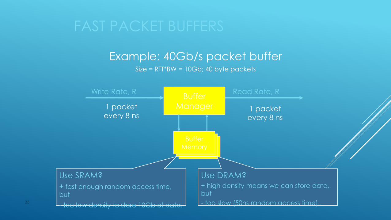
FAST PACKET BUFFERS
33
Example: 40Gb/s packet bufferSize = RTT*BW = 10Gb; 40 byte packets
Write Rate, R
1 packet
every 8 ns
Read Rate, R
1 packet
every 8 ns
Buffer
Manager
Buffer
Memory
Use SRAM?
+ fast enough random access time,
but
- too low density to store 10Gb of data.
Use SRAM?
+ fast enough random access time,
but
- too low density to store 10Gb of data.
Use DRAM?+ high density means we can store data,
but
- too slow (50ns random access time).
Use DRAM?+ high density means we can store data,
but
- too slow (50ns random access time).

PACKET CACHES
34
DRAM Buffer Memory
Buffer
Manager
SRAM
Arriving
Packets
Departing
Packets12
Q
2
1234
345
123456
Small ingress SRAM
cache of FIFO headscache of FIFO tails
5556
9697
8788
57585960
899091
1
Q
2
Small ingress SRAM
1
57 6810 9
79 81011
1214 1315
5052 515354
8688 878991 90
8284 838586
9294 9395 68 7911 10
1
Q
2
DRAM Buffer Memory
b>>1 packets at a time
OUTLINE
Background
What is a router?
Why do we need faster routers?
Why are they hard to build?
Architectures and techniques
The evolution of router architecture.
IP address lookup.
Packet buffering.
Switching.
The Future
35
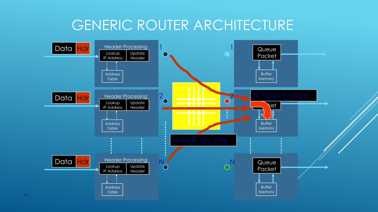
GENERIC ROUTER ARCHITECTURE
36
Lookup
IP Address
Update
Header
Header Processing
Address
Table
Address
Table
Lookup
IP Address
Update
Header
Header Processing
Address
Table
Address
Table
Lookup
IP Address
Update
Header
Header Processing
Address
Table
Address
Table
QueuePacket
Buffer
Memory
Buffer
Memory
QueuePacket
Buffer
Memory
Buffer
Memory
QueuePacket
Buffer
Memory
Buffer
Memory
Data Hdr
Data Hdr
Data Hdr
1
2
N
1
2
N
N times line rate
N times line rate

GENERIC ROUTER ARCHITECTURE
37
Lookup
IP Address
Update
Header
Header Processing
Address
Table
Address
Table
Lookup
IP Address
Update
Header
Header Processing
Address
Table
Address
Table
Lookup
IP Address
Update
Header
Header Processing
Address
Table
Address
Table
QueuePacket
Buffer
Memory
Buffer
Memory
QueuePacket
Buffer
Memory
Buffer
Memory
QueuePacket
Buffer
Memory
Buffer
Memory
Data Hdr
Data Hdr
Data Hdr
1
2
N
1
2
N
Data Hdr
Data Hdr
Data Hdr
Scheduler
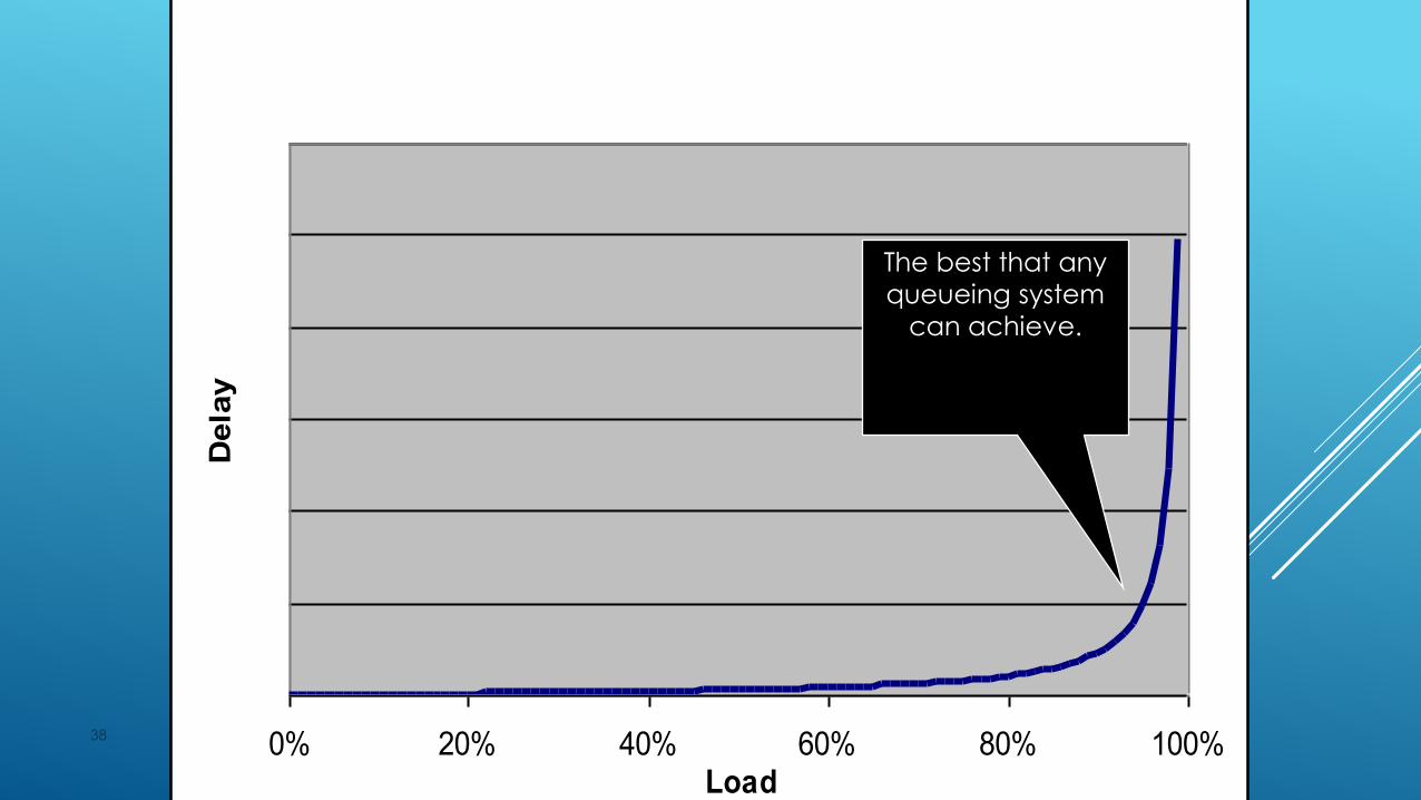
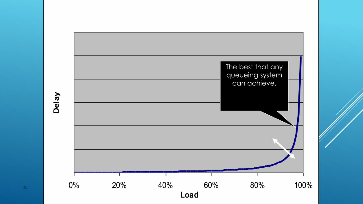
OUTPUT BUFFERED SWITCHES
38 0% 20% 40% 60% 80% 100%Load
Dela
y
The best that any
queueing system
can achieve.

INPUT BUFFERED SWITCHESHEAD OF LINE BLOCKING
39 0% 20% 40% 60% 80% 100%Load
Dela
y
The best that any
queueing system
can achieve.
2 2 58%

HEAD OF LINE BLOCKING
40
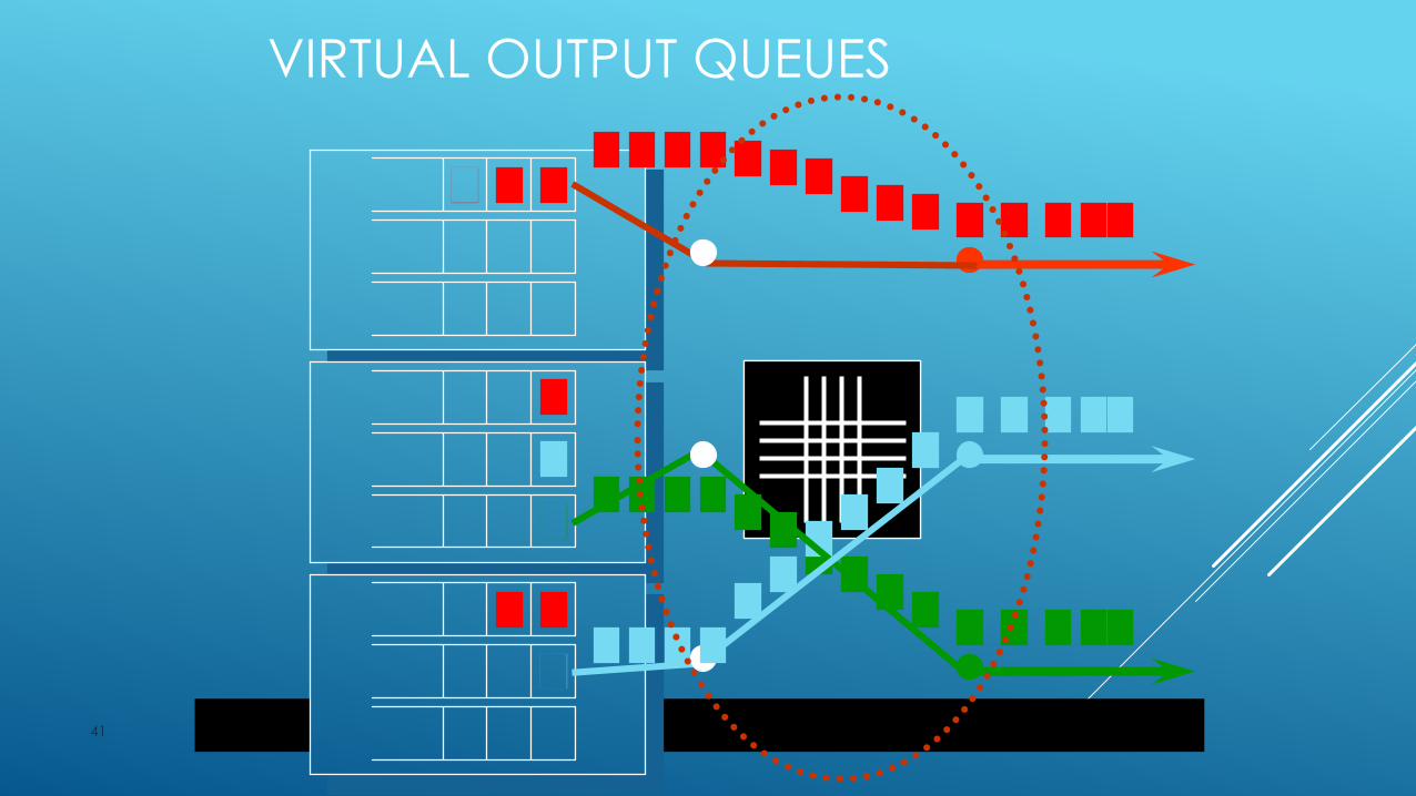
VIRTUAL OUTPUT QUEUES
41
A ROUTER WITH VIRTUAL OUTPUT QUEUES
42 0% 20% 40% 60% 80% 100%Load
Dela
y
The best that any
queueing system
can achieve.
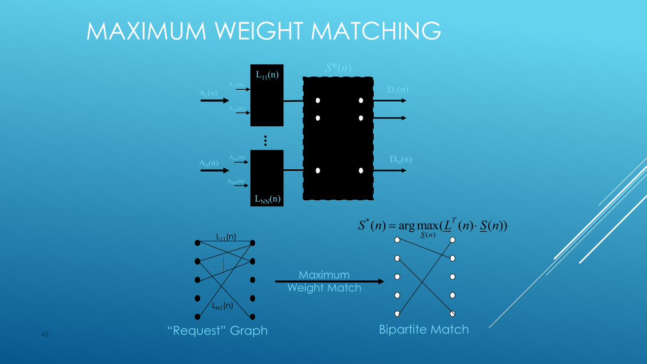
MAXIMUM WEIGHT MATCHING
43
A1(n)
N N
LNN(n)
A1N(n)
A11(n)
L11(n)
1 1
AN(n)
ANN(n)
AN1(n)
D1(n)
DN(n)
L11(n)
LN1(n)
“Request” Graph Bipartite Match
S*(n)
Maximum
Weight Match
*
( )( ) arg max( ( ) ( ))
T
S nS n L n S n
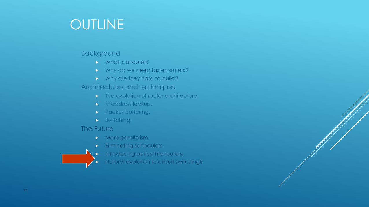
OUTLINE
Background
What is a router?
Why do we need faster routers?
Why are they hard to build?
Architectures and techniques
The evolution of router architecture.
IP address lookup.
Packet buffering.
Switching.
The Future
More parallelism.
Eliminating schedulers.
Introducing optics into routers.
Natural evolution to circuit switching?
44
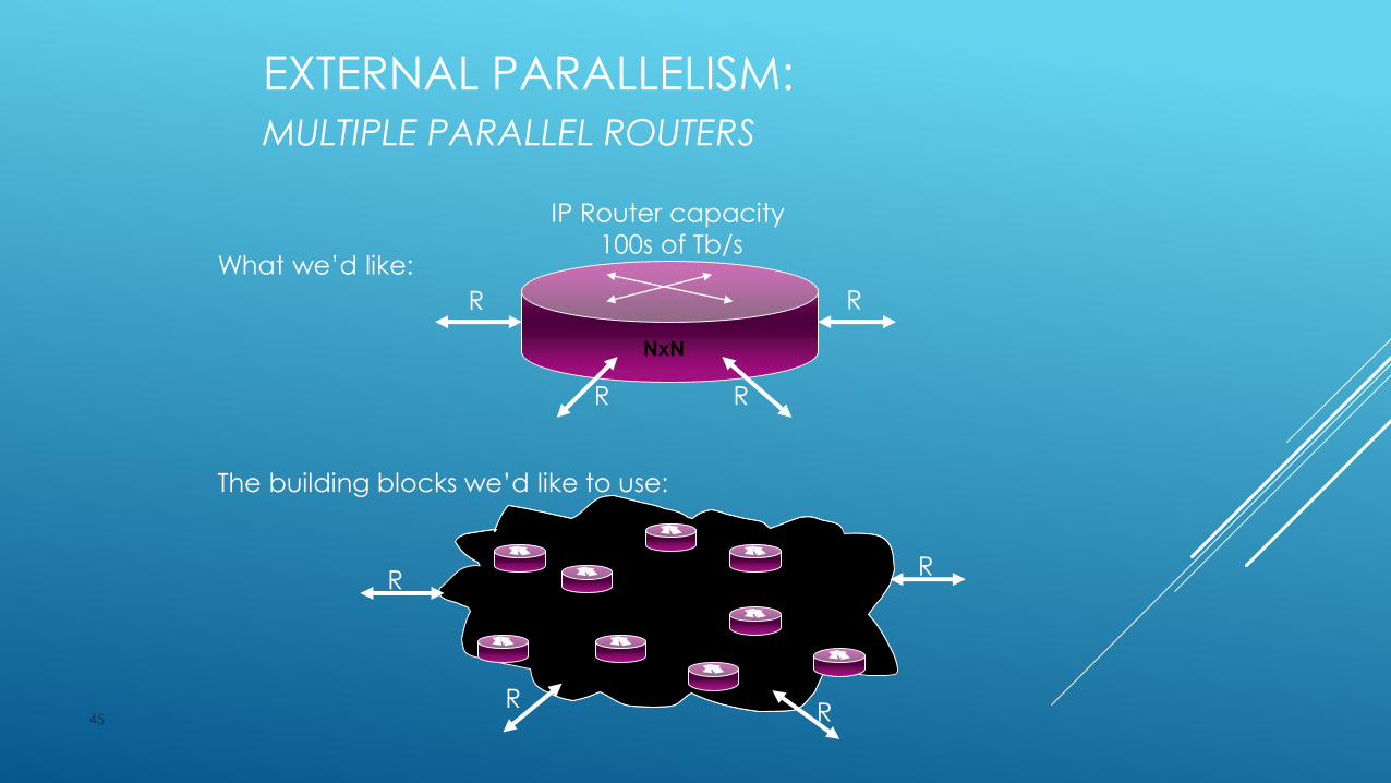
EXTERNAL PARALLELISM:
MULTIPLE PARALLEL ROUTERS
45
What we’d like:
R
R R
R
The building blocks we’d like to use:
R
RR
R
NxN
IP Router capacity
100s of Tb/s
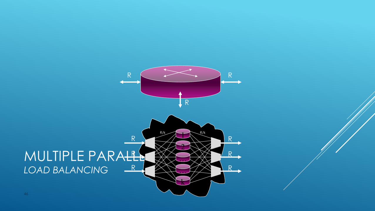
MULTIPLE PARALLEL ROUTERS LOAD BALANCING
46
R R
R
1
2
…
…
k
R
R
R
R/k R/k
R
R
R
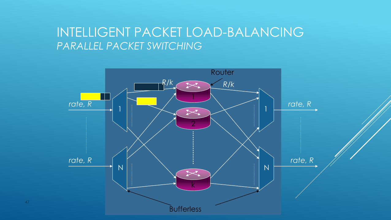
INTELLIGENT PACKET LOAD-BALANCINGPARALLEL PACKET SWITCHING
47
1
2
k
1
N
rate, R
rate, R
rate, R
rate, R
1
N
Router
Bufferless
R/k R/k
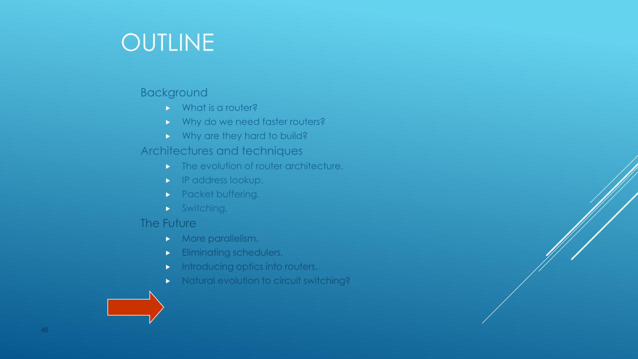
OUTLINE
Background
What is a router?
Why do we need faster routers?
Why are they hard to build?
Architectures and techniques
The evolution of router architecture.
IP address lookup.
Packet buffering.
Switching.
The Future
More parallelism.
Eliminating schedulers.
Introducing optics into routers.
Natural evolution to circuit switching?
48

DO OPTICS BELONG IN ROUTERS?
They are already there.
Connecting linecards to switches.
Optical processing doesn’t belong on the linecard.
You can’t buffer light.
Minimal processing capability.
Optical switching can reduce power.
49
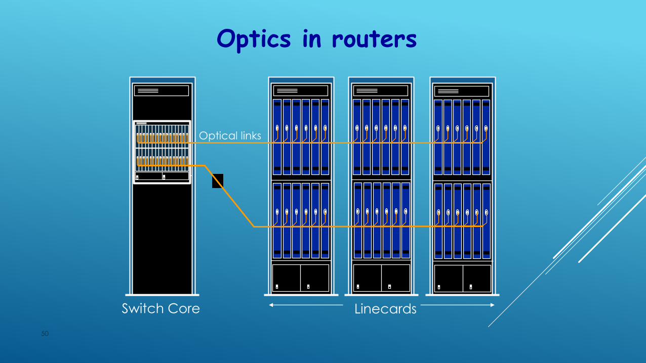
50
Optics in routers
Switch Core Linecards
Optical links
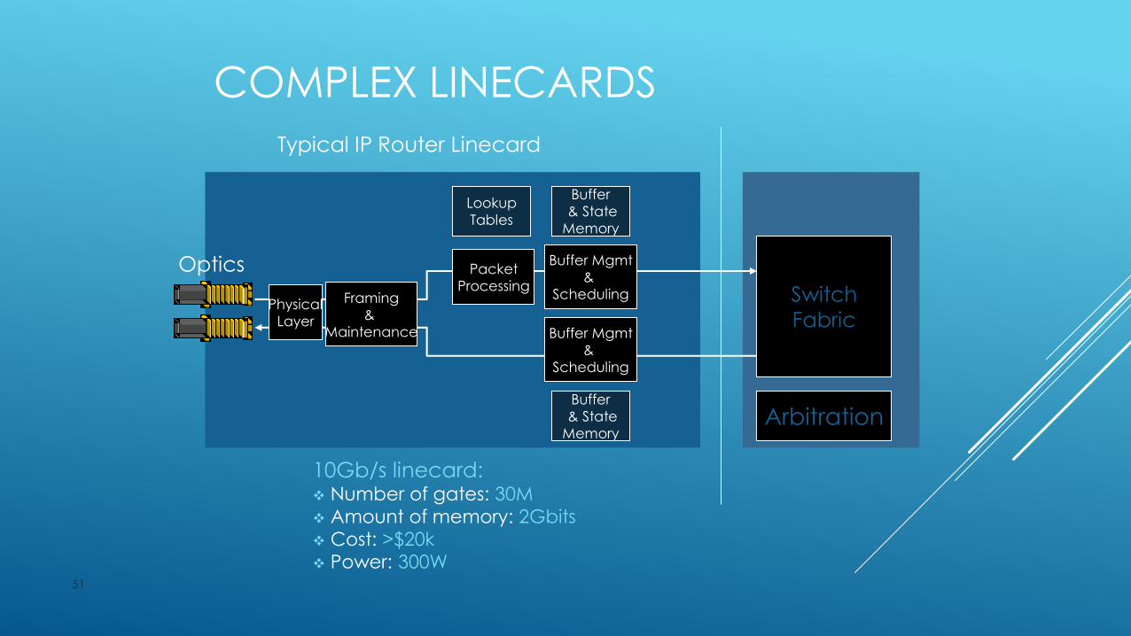
COMPLEX LINECARDS
51
Physical
Layer
Framing
&
Maintenance
Packet
Processing
Buffer Mgmt
&
Scheduling
Buffer Mgmt
&
Scheduling
Buffer
& State
Memory
Buffer
& State
Memory
Typical IP Router Linecard
10Gb/s linecard: Number of gates: 30M
Amount of memory: 2Gbits
Cost: >$20k
Power: 300W
Lookup
Tables
Switch
Fabric
Arbitration
Optics
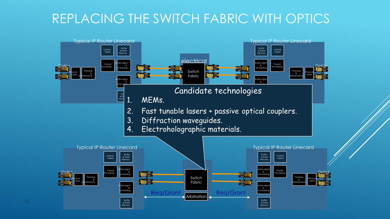
REPLACING THE SWITCH FABRIC WITH OPTICS
52
Switch
Fabric
Arbitration
PhysicalLayer
Framing&
Maintenance
PacketProcessing
Buffer Mgmt&
Scheduling
Buffer Mgmt&
Scheduling
Buffer& State
Memory
Buffer& State
Memory
Typical IP Router Linecard
LookupTables
Optics
PhysicalLayer
Framing&
Maintenance
PacketProcessing
Buffer Mgmt&
Scheduling
Buffer Mgmt&
Scheduling
Buffer& State
Memory
Buffer& State
Memory
Typical IP Router Linecard
LookupTables
Opticselectrical
Switch
Fabric
Arbitration
PhysicalLayer
Framing&
Maintenance
PacketProcessing
Buffer Mgmt&
Scheduling
Buffer Mgmt&
Scheduling
Buffer& State
Memory
Buffer& State
Memory
Typical IP Router Linecard
LookupTables
Optics
PhysicalLayer
Framing&
Maintenance
PacketProcessing
Buffer Mgmt&
Scheduling
Buffer Mgmt&
Scheduling
Buffer& State
Memory
Buffer& State
Memory
Typical IP Router Linecard
LookupTables
Optics
optical
Req/Grant Req/Grant
Candidate technologies1. MEMs.
2. Fast tunable lasers + passive optical couplers.3. Diffraction waveguides.4. Electroholographic materials.
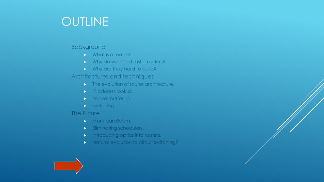
OUTLINE
Background
What is a router?
Why do we need faster routers?
Why are they hard to build?
Architectures and techniques
The evolution of router architecture.
IP address lookup.
Packet buffering.
Switching.
The Future
More parallelism.
Eliminating schedulers.
Introducing optics into routers.
Natural evolution to circuit switching?
53
EVOLUTION TO CIRCUIT SWITCHING
Optics enables simple, low-power, very high capacity circuit switches.
The Internet was packet switched for two reasons:
Expensive links: statistical multiplexing.
Resilience: soft-state routing.
Neither reason holds today.
54

FAST LINKS, SLOW ROUTERS
55
0,1
1
10
100
1000
10000
1985 1990 1995 2000
Fib
er
Ca
pa
cit
y (
Gb
it/s
)
Fiber optics DWDM
0.1
1
10
100
1000
10000
1985 1990 1995 2000
Sp
ec95In
t C
PU
resu
lts
Processing Power Link Speed (Fiber)
2x / 2 years 2x / 7 months
Source: SPEC95Int; Prof. Miller, Stanford Univ.
OUTLINE
Background
What is a router?
Why do we need faster routers?
Why are they hard to build?
Architectures and techniques
The evolution of router architecture.
IP address lookup.
Packet buffering.
Switching.
The Future
More parallelism.
Eliminating schedulers.
Introducing optics into routers.
Natural evolution to circuit switching?
56
REFERENCES
General
1. J. S. Turner “Design of a Broadcast packet switching network”, IEEE Trans Comm, June 1988, pp. 734-743.
2. C. Partridge et al. “A Fifty Gigabit per second IP Router”, IEEE Trans Networking, 1998.
3. N. McKeown, M. Izzard, A. Mekkittikul, W. Ellersick, M. Horowitz, “The Tiny Tera: A Packet Switch Core”, IEEE Micro Magazine, Jan-Feb 1997.
Fast Packet Buffers
1. Sundar Iyer, Ramana Rao, Nick McKeown “Design of a fast packet buffer”, IEEE HPSR 2001, Dallas.
57

REFERENCESIP Lookups
1. A. Brodnik, S. Carlsson, M. Degermark, S. Pink. “Small Forwarding Tables for Fast Routing Lookups”, Sigcomm 1997, pp 3-14.
2. B. Lampson, V. Srinivasan, G. Varghese. “ IP lookups using multiway and multicolumn search”, Infocom 1998, pp 1248-56, vol. 3.
3. M. Waldvogel, G. Varghese, J. Turner, B. Plattner. “Scalable high speed IP routing lookups”, Sigcomm 1997, pp 25-36.
4. P. Gupta, S. Lin, N. McKeown. “Routing lookups in hardware at memory access speeds”, Infocom 1998, pp 1241-1248, vol. 3.
5. S. Nilsson, G. Karlsson. “Fast address lookup for Internet routers”, IFIP Intl Conf on Broadband Communications, Stuttgart, Germany, April 1-3, 1998.
6. V. Srinivasan, G.Varghese. “Fast IP lookups using controlled prefix expansion”, Sigmetrics, June 1998.
58
REFERENCESSwitching
N. McKeown, A. Mekkittikul, V. Anantharam, and J. Walrand. Achieving 100% Throughput in an Input-Queued Switch. IEEE Transactions on Communications, 47(8), Aug 1999.
A. Mekkittikul and N. W. McKeown, "A practical algorithm to achieve 100% throughput in input-queued switches," in Proceedings of IEEE INFOCOM '98, March 1998.
L. Tassiulas, “Linear complexity algorithms for maximum throughput in radio networks and input queued switchs,” in Proc. IEEE INFOCOM ‘98, San Francisco CA, April 1998.
D. Shah, P. Giaccone and B. Prabhakar, “An efficient randomized algorithm for input-queued switch scheduling,” in Proc. Hot Interconnects 2001.
J. Dai and B. Prabhakar, "The throughput of data switches with and without speedup," in Proceedings of IEEE INFOCOM '00, Tel Aviv, Israel, March 2000, pp. 556 -- 564.
C.-S. Chang, D.-S. Lee, Y.-S. Jou, “Load balanced Birkhoff-von Neumann switches,” Proceedings of IEEE HPSR ‘01, May 2001, Dallas, Texas.
59

REFERENCES
Future
C.-S. Chang, D.-S. Lee, Y.-S. Jou, “Load balanced
Birkhoff-von Neumann switches,” Proceedings of IEEE
HPSR ‘01, May 2001, Dallas, Texas.
Pablo Molinero-Fernndez, Nick McKeown "TCP Switching: Exposing circuits to IP" Hot Interconnects IX, Stanford
University, August 2001
S. Iyer, N. McKeown, "Making parallel packet switches
practical," in Proc. IEEE INFOCOM `01, April 2001, Alaska.
60

MULTI PROTOCOL LABEL SWITCHING
(MPLS)
WHY INTERNET PROTOCOL IS
POPULAR?
Robustness
Aggregation and Hierarchy

ISSUES WITH INTERNET PROTOCOL
IP address lookup
No QoS
Best Effort

OBJECTIVES OF MPLS
Speed up IP packet forwarding
– By cutting down on the amount of processing at every intermediate router
Prioritize IP packet forwarding
– By providing ability to engineer traffic flow and assure differential QoS
Without losing on the flexibility of IP based network

MPLS – KEY IDEAS
Use a fixed length label in the packet header to decide packetforwarding
A path is established between two end points.
At ingress a packet is classified into a Forwarding EquivalenceClass.
FEC to which it is assigned is encoded as a short fixed lengthvalue – Label.
Packet is forwarded along with label to next hop.
MPLS – KEY IDEAS
No further analysis of header by subsequent routers, forwarding is
driven by the labels.
Label is used as index for next hop and new label.
At the Egress, label is removed and packet is forwarded to final
destination based on the IP packet header
MPLS HEADER
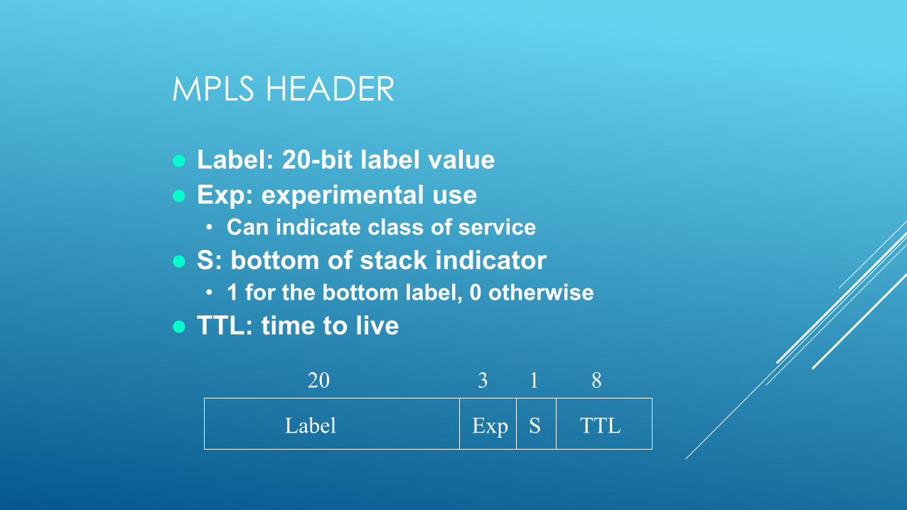
Label: 20-bit label value
Exp: experimental use
• Can indicate class of service
S: bottom of stack indicator• 1 for the bottom label, 0 otherwise
TTL: time to live
Label Exp S TTL
20 3 1 8

Forwarding Equivalence
Class Forwarding Equivalence Class (FEC): A subset of
packets that are all treated the same way by anLSR.
A packet is assigned to an FEC at the ingress ofan MPLS domain.
Subset can be based on • Address prefix
• Host address
• QoS
Forwarding Equivalence
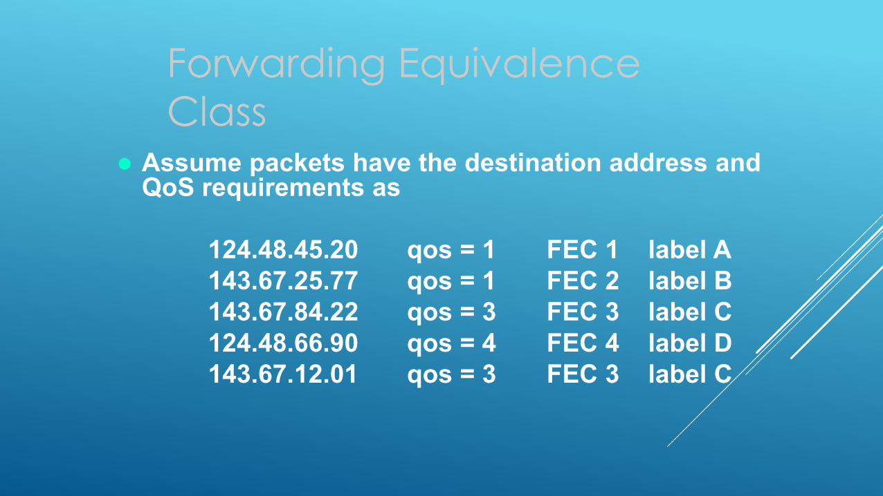
Class Assume packets have the destination address and
QoS requirements as
124.48.45.20 qos = 1 FEC 1 label A
143.67.25.77 qos = 1 FEC 2 label B
143.67.84.22 qos = 3 FEC 3 label C
124.48.66.90 qos = 4 FEC 4 label D
143.67.12.01 qos = 3 FEC 3 label C

LABEL DISTRIBUTION PROTOCOL
(LDP)
LDP is the set of procedures to inform other LSRs about binding between FEC and label.
• Piggyback on existing protocols(BGP, OSPF,RSVP)
• Separate Label Distribution Protocol
MPLS LSPS ESTABLISHING
Static Configuration
-Operator can provision LSPs by statically configuring label
mappings at each LSRs.
MPLS LSPS ESTABLISHING- LDP
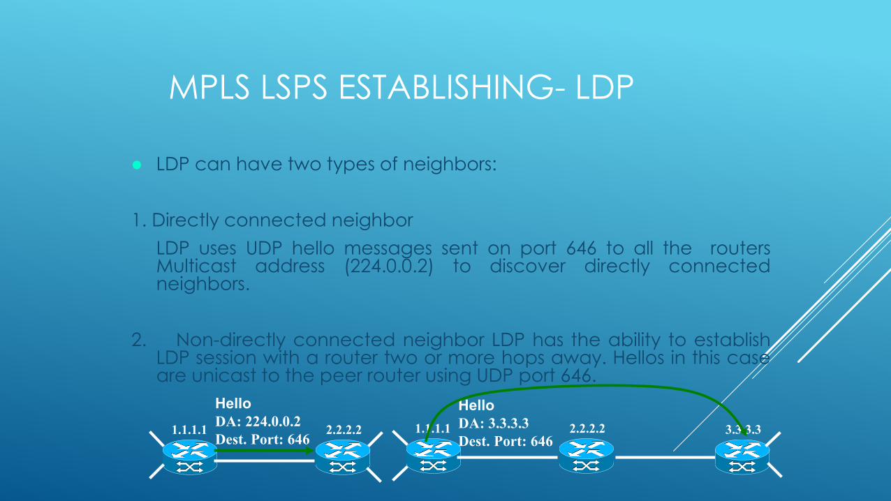
LDP can have two types of neighbors:
1. Directly connected neighbor
LDP uses UDP hello messages sent on port 646 to all the routersMulticast address (224.0.0.2) to discover directly connectedneighbors.
2. Non-directly connected neighbor LDP has the ability to establishLDP session with a router two or more hops away. Hellos in this caseare unicast to the peer router using UDP port 646.
Hello
DA: 224.0.0.2
Dest. Port: 6462.2.2.21.1.1.1
Hello
DA: 3.3.3.3
Dest. Port: 6462.2.2.21.1.1.1 3.3.3.3
MPLS LSPS ESTABLISHING- LDP
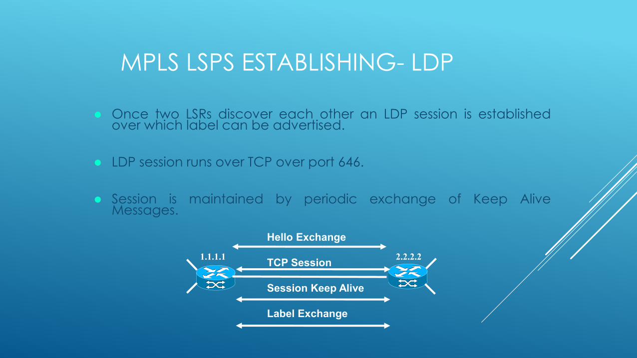
Once two LSRs discover each other an LDP session is establishedover which label can be advertised.
LDP session runs over TCP over port 646.
Session is maintained by periodic exchange of Keep AliveMessages.
Hello Exchange
TCP Session
Session Keep Alive
Label Exchange
2.2.2.21.1.1.1
MPLS LSPS ESTABLISHING- RSVP TE
The ingress LSR computes a path to egress LSR using the CSPFalgorithm.
The computed path is encoded into an Explicit Route Object (ERO)and included in RSVP TE Path messages.
Each router along the path creates state for the path and forwardsthe message to the next router in ERO.
Egress LSR validates the path message and creates a Resv messagecontaining a Label for the LSP.
The Resv message is sent back to ingress LSR on the same pathfollowed by path message.
When Resv message reaches the ingress LSR , LSP setup is created.

LABEL DISTRIBUTION METHODS
Unsolicited DownstreamLabel Distribution
Rd discovers a ‘next hop’ fora particular FEC
Rd generates a label for theFEC and communicatesthe binding to Ru
Ru inserts the binding into itsforwarding tables
Downstream on DemandLabel Distribution
Ru recognizes Rd as itsnext-hop for an FEC
A request is made to Rd fora binding between the FECand a label
If Rd recognizes the FECand has a next hop for it, itcreates a binding and repliesto the Ru
Label-FEC Binding Label-FEC Binding
Request for BindingRu Rd RdRu
LABEL DISTRIBUTION AND MANAGEMENT
Label Distribution Control Mode
– Independent LSP control
– Ordered LSP control
LABEL DISTRIBUTION AND MANAGEMENT
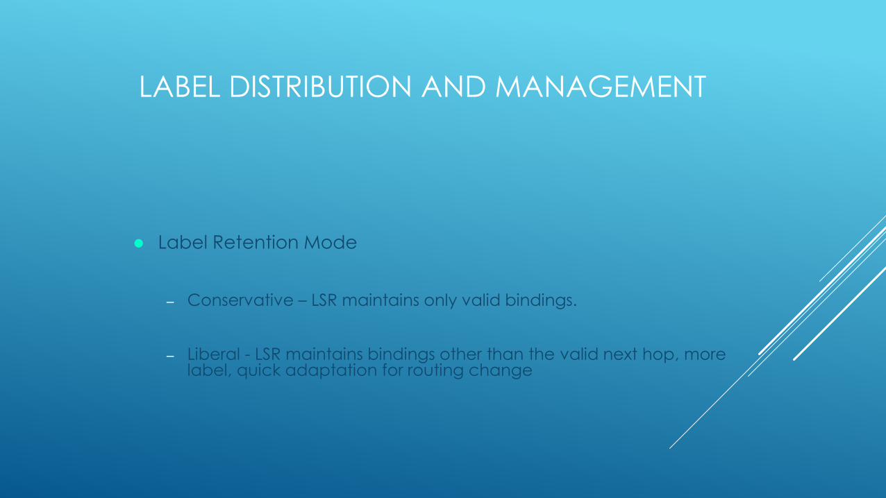
Label Retention Mode
– Conservative – LSR maintains only valid bindings.
– Liberal - LSR maintains bindings other than the valid next hop, more label, quick adaptation for routing change
LABEL INFORMATION BASE (LIB)
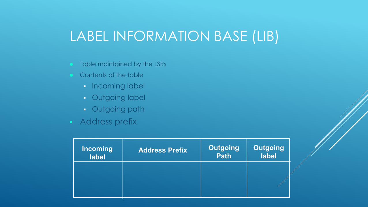
Table maintained by the LSRs
Contents of the table
Incoming label
Outgoing label
Outgoing path
Address prefix
Incoming
labelAddress Prefix Outgoing
Path
Outgoing
label

NEXT HOP LABEL FORWARDING ENTRY
(NHLFE)
Used for forwarding a labeled packet.
Contains the following information:
- Packets next hop.
- Operation to be performed on label stack i.e. (One of thefollowing)
Replace the label on the label stack with a specified new
label.
Pop the label stack.
Replace the label on the label stack with a specified new
label and then push one on more specified new label onto the
label stack.
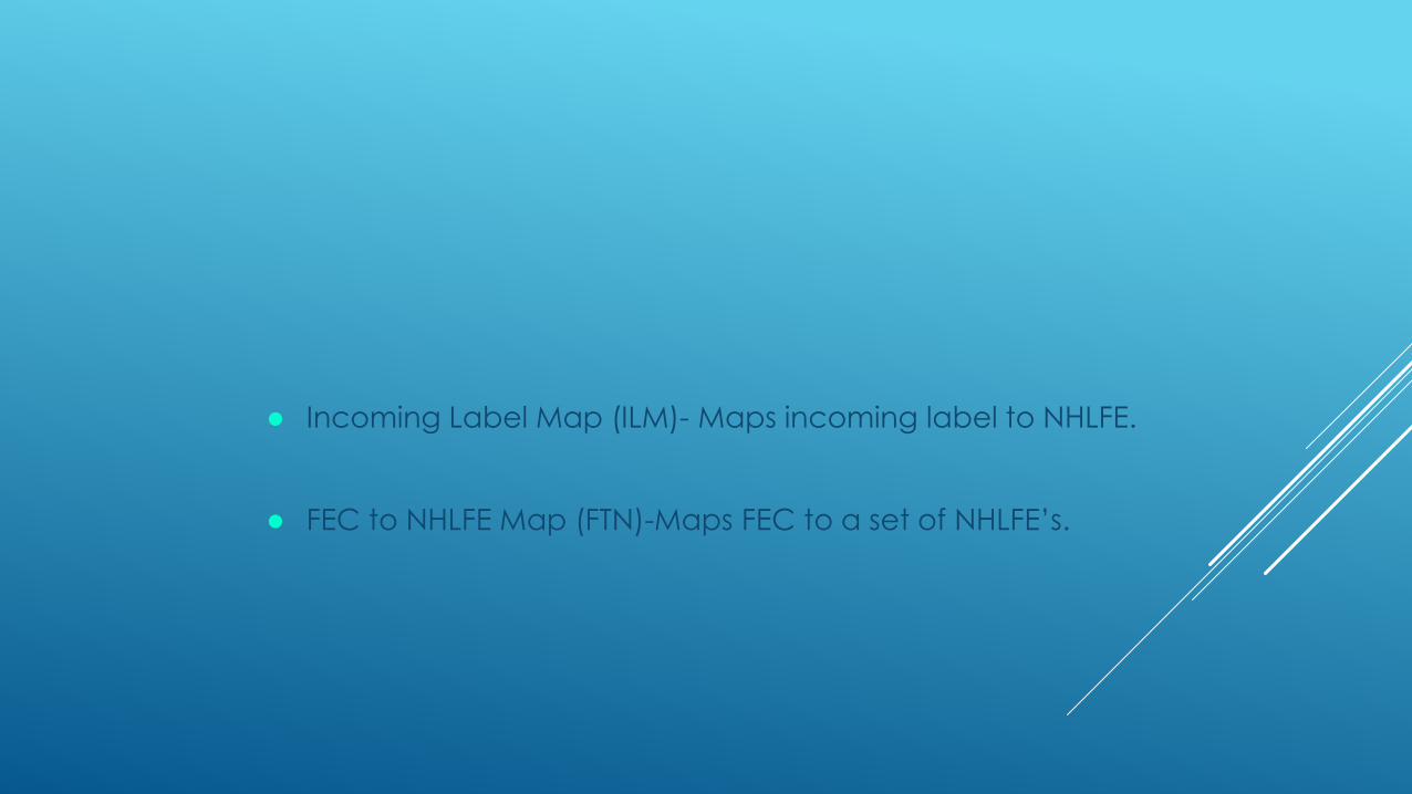
Incoming Label Map (ILM)- Maps incoming label to NHLFE.
FEC to NHLFE Map (FTN)-Maps FEC to a set of NHLFE’s.
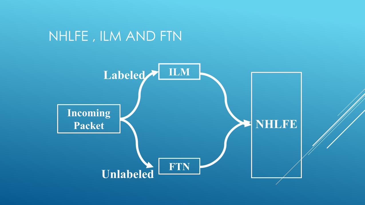
NHLFE , ILM AND FTN
Incoming
Packet
ILM
FTN
NHLFE
Labeled
Unlabeled

LABEL STACK
A labeled packet can contain more than one label.
Labels are maintained in FIFO stack.
Processing always done on the top label.
MPLS support a hierarchy and notion of LSP Tunnel.

OPERATIONS ON LABEL STACK
Swap
Pop
Push
OPERATION ON LABEL STACK-SWAP
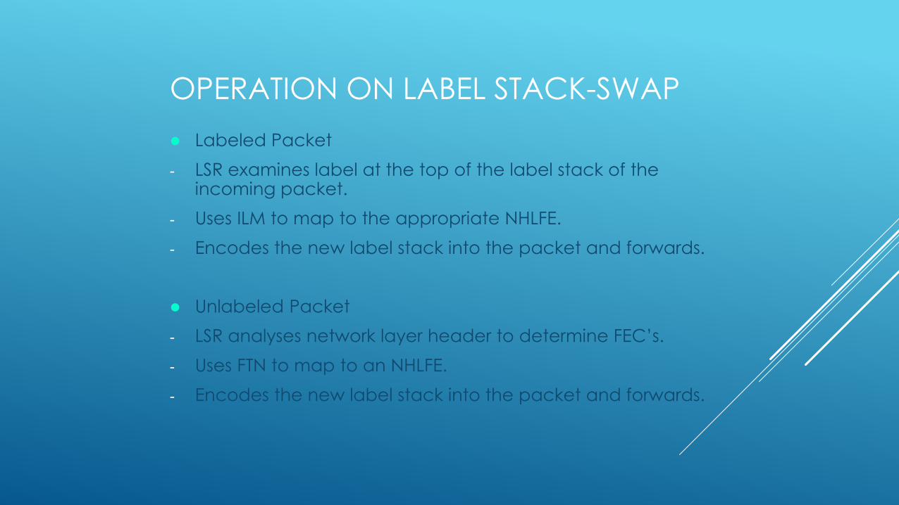
Labeled Packet
- LSR examines label at the top of the label stack of the incoming packet.
- Uses ILM to map to the appropriate NHLFE.
- Encodes the new label stack into the packet and forwards.
Unlabeled Packet
- LSR analyses network layer header to determine FEC’s.
- Uses FTN to map to an NHLFE.
- Encodes the new label stack into the packet and forwards.
OPERATION ON LABEL STACK
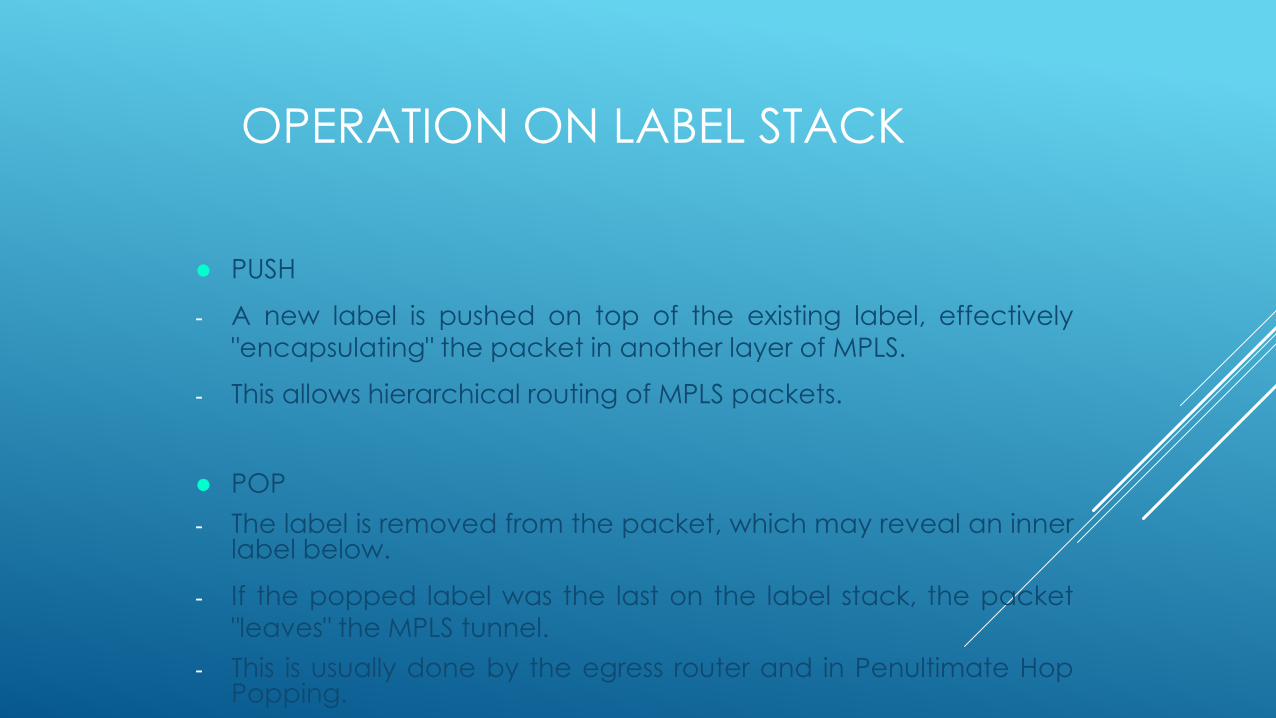
PUSH
- A new label is pushed on top of the existing label, effectively
"encapsulating" the packet in another layer of MPLS.
- This allows hierarchical routing of MPLS packets.
POP
- The label is removed from the packet, which may reveal an innerlabel below.
- If the popped label was the last on the label stack, the packet
"leaves" the MPLS tunnel.
- This is usually done by the egress router and in Penultimate HopPopping.

OPERATION ON LABEL STACK
IP
L1
IP
L2
IP
L1
IP
L1
L2
IP
L1
IP
L1
L2
SWAP PUSH
POP
Label Switched Path
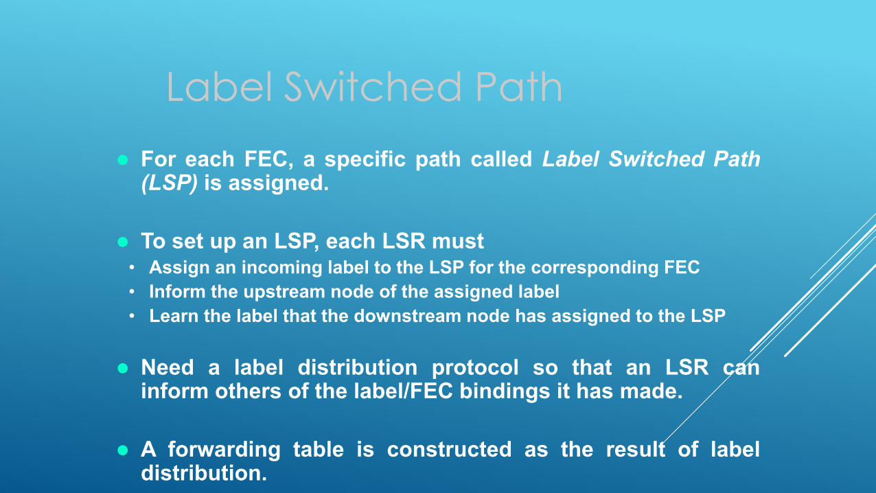
For each FEC, a specific path called Label Switched Path(LSP) is assigned.
To set up an LSP, each LSR must• Assign an incoming label to the LSP for the corresponding FEC
• Inform the upstream node of the assigned label
• Learn the label that the downstream node has assigned to the LSP
Need a label distribution protocol so that an LSR caninform others of the label/FEC bindings it has made.
A forwarding table is constructed as the result of labeldistribution.
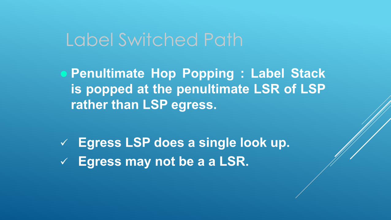
Penultimate Hop Popping : Label Stack
is popped at the penultimate LSR of LSP
rather than LSP egress.
Egress LSP does a single look up.
Egress may not be a a LSR.
Label Switched Path

LSP Next Hop
Labeled Packet
- As selected by the NHLFE entry used forforwarding that packet.
FEC
- As selected by the NHLFE entry indexedby a label corresponding to that FEC.
Label Switched Path
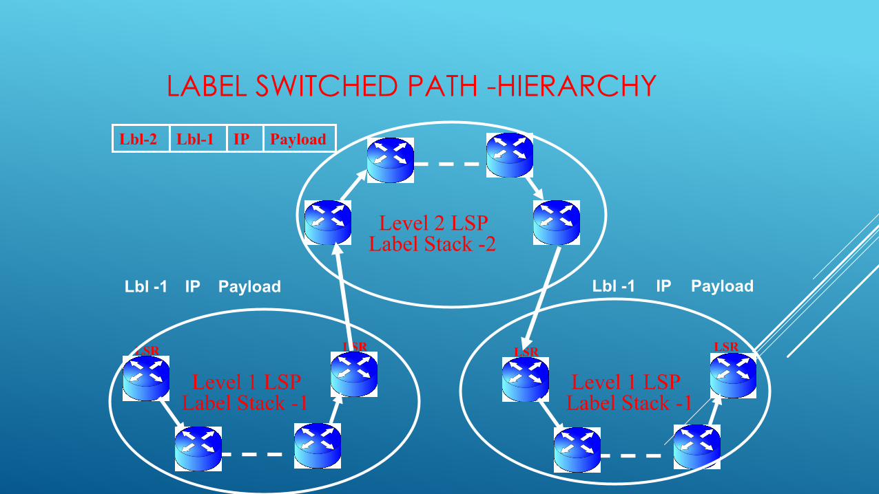
LABEL SWITCHED PATH -HIERARCHY
Lbl -1 IP Payload
LSR LSR LSR LSR
Level 1 LSP Level 1 LSP
Level 2 LSP
Label Stack -1 Label Stack -1
Label Stack -2
Lbl -1 IP Payload
Lbl-2 Lbl-1 IP Payload

LABEL STACK - HIERARCHY
MPLS supports hierarchy.
Each LSR processes the topmost label.
If traffic crosses several networks, it can be tunneled across them
Advantage – reduces the LIB table of each router drastically
Layer 2 Header Label 3 IP PacketLabel 2 Label 1
MPLS Domain 1
MPLS Domain 2
MPLS Domain 3
Slide by ByTamrat Bayle, Reiji Aibara, Kouji Nishimura

LABEL SWITCHED PATH -TUNNEL
Level 2 LSPLabel Stack -2
Explicitely
Routed Tunnel
Hop By Hop Tunnel
Independent
- Each LSR on recognizing a particular FEC
makes an independent decision to bind a label
to it and distribute that binding.
Ordered
- An LSR binds a label to a FEC only if it is the
egress LSR to that FEC or it has already a
binding for that FEC from its next hop for that
FEC.
Label Switched Path -
Control
LSP Route Selection
Method for selecting the LSP for a particularFEC.
Hop-by-hop routing: Each node independentlychoose the next hop for a FEC.
Explicit routing (ER): the sender LSR canspecify an explicit route for the LSP• Explicit route can be selected ahead of time or
dynamically
95
Explicitly Routed LSP
Advantages
• Can establish LSP’s based on policy, QoS, etc.
• Can have pre-established LSP’s that can be used in
case of failures.
• It makes MPLS explicit routing much more efficient
than the alternative of IP source routing.
AGGREGATION
In the MPLS Domain, all the traffic in a set of FECs might
follow the same route.
The procedure of binding a single label to a union of FECs
which is itself a FEC, and applying that label to all traffic in
the union is known as Aggregation.
Reduces the number of labels.
Reduces the amount of label distribution control traffic.
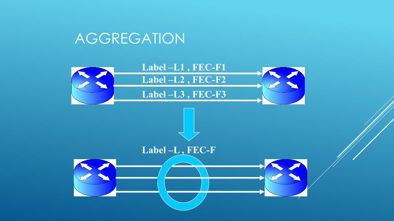
AGGREGATION
Label –L2 , FEC-F2
Label –L3 , FEC-F3
Label –L1 , FEC-F1
Label –L , FEC-F
LABEL MERGING
Label Merging is the capability of forwarding twodifferent packets belonging to the same FEC, butarriving with different labels, with the same outgoinglabel.
An LSR is label merging capable if it can receive twopackets from different incoming interfaces, and/orwith different labels, and send both packets out thesame outgoing interface with the same label.
Once transmitted, the information that they arrivefrom different interfaces and/or with different labels islost.

MPLS PROTECTION
MPLS OAM*: Fault detection and diagnosis
TRAFFIC PROTECTION: Route traffic away from failed node/link.
NODE PROTECTION: Enhance node availability.
* Operation, Administration and Maintenance.
SOME MPLS TRANSPORT PROBLEMS
Data plane fails (“Black Holes”).
Connectivity Problem, Broken link.
What path is being taken?

LEVERAGING MPLS OAM
Difficult to detect MPLS failure:
Traditional ping may not be successful
Difficult to troubleshoot MPLS failure:
Manual hop/hop work
MPLS OAM facilitates and speeds up troubleshooting of
MPLS failures.

LSP PING/TRACEROUTE
Requirements:
- Detect MPLS Black holes.
- Isolate MPLS faults.
- Diagnose connectivity problems.
Solutions:
- LSP ping for connectivity checks.
- LSP traceroute for hop-by-hop fault localization.
- LSP traceroute for path tracing.

TROUBLESHOOTING
R3 does not forward echo-req to R4, replies back to R1.R1 R2 R3 R4
SA DA = 127/8 ECHO
30 50
LSP BrokenMPLS Echo Reply
TRAFFIC PROTECTION
Detect the fault.
Divert the traffic away from fault.
Mechanisms:
- LDP signaled LSPs
- Backup LSP
- Fast Reroute

LDP SIGNALED LSPS
Path protection depends on IGP reconvergence.
In case of link/node failure:
i) Remove label mapping for the LSP from FIB.
ii) Wait for new shortest path and matching label.

BACKUP LSPS
R1 R2 R4 R5
R6 R7
R3
Path Err
Backup Path for RSVP-TE signaled LSP
Backup path

FAST REROUTE
Repair failure at the node that detects failure (Point of Local Repair or PLR).
One to one backup:
Each LSR creates a detour LSP for each protected LSP.
Facility Bypass:
Single bypass LSP for all protected LSPs
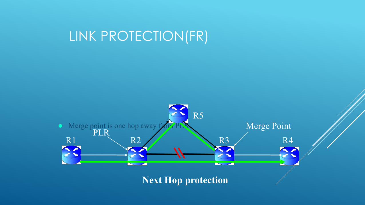
LINK PROTECTION(FR)
Merge point is one hop away from PLR.
R1 R2 R3 R4
R5
Next Hop protection
Merge PointPLR

NODE PROTECTION(FR)
Merge point is two hops away from PLR.
R1 R2 R4 R5
R6 R7
R3
Next-Next Hop protection
PLRMerge Point
NODE PROTECTION
Resilient LSRs.
Software support required to take advantage of Hardware redundancy.
Nonstop Routing:
- Replicate all state changes to backup control card.
- State synchronization required.
Nonstop Forwarding:
- Graceful restart of the failed node.
- Protocol extensions at neighbors.
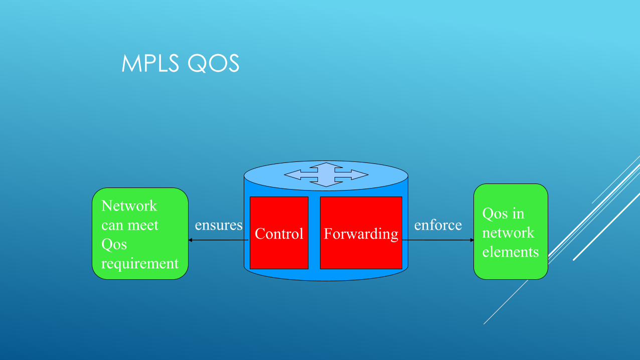
MPLS QOS
Control Forwarding
Network
can meet
Qos
requirement
Qos in
network
elements
ensures enforce
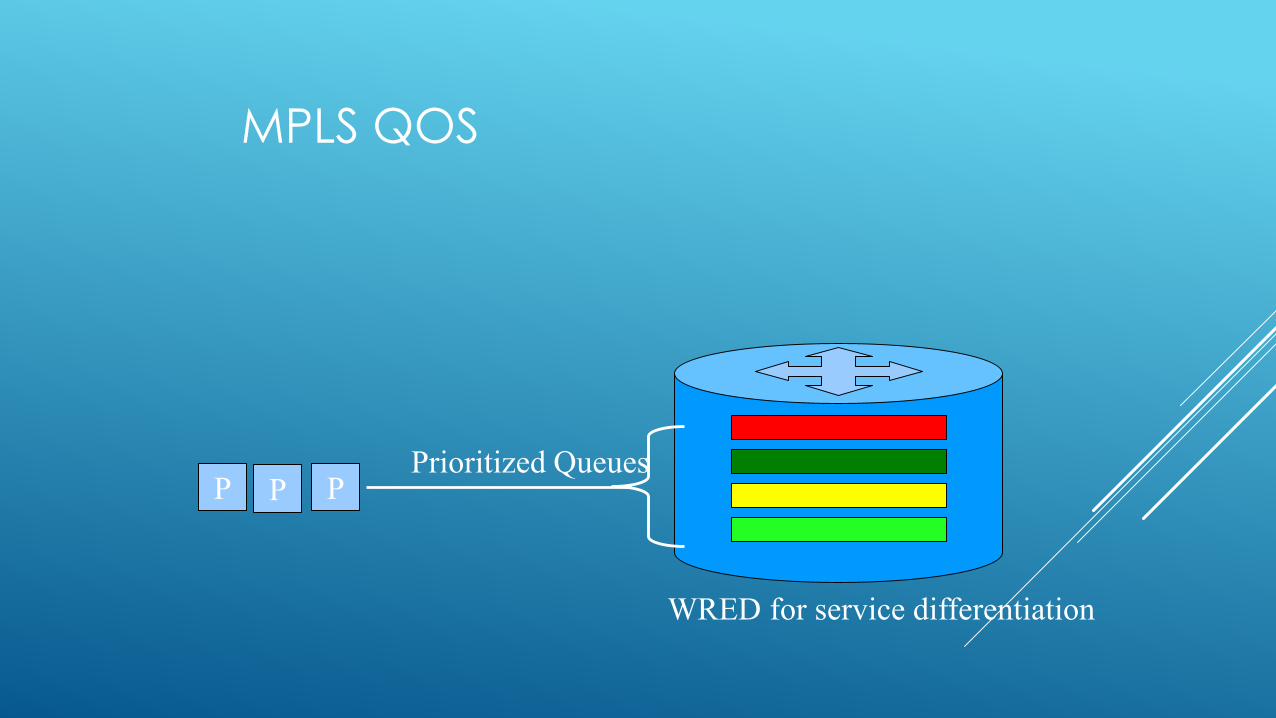
MPLS QOS
PP P PPrioritized Queues
WRED for service differentiation
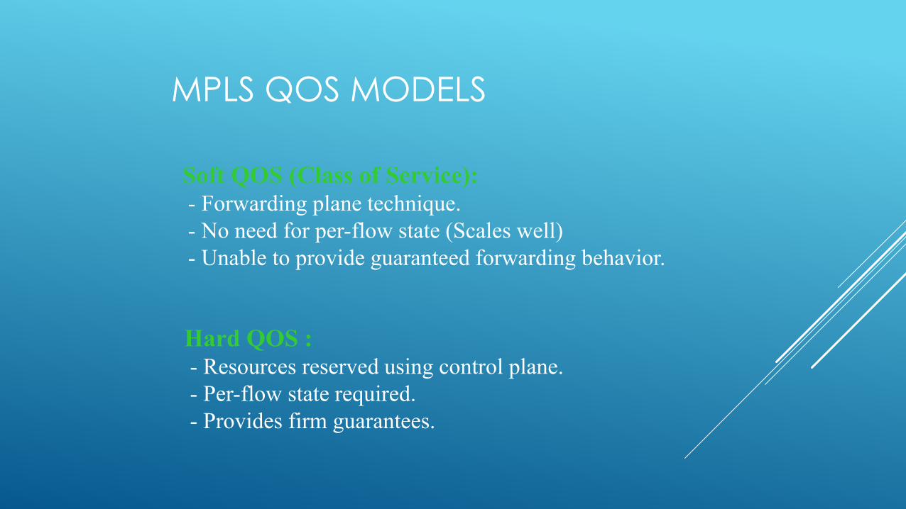
MPLS QOS MODELS
Soft QOS (Class of Service):
- Forwarding plane technique.
- No need for per-flow state (Scales well)
- Unable to provide guaranteed forwarding behavior.
Hard QOS :
- Resources reserved using control plane.
- Per-flow state required.
- Provides firm guarantees.
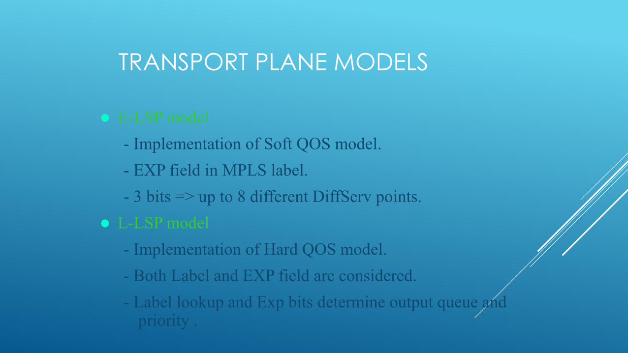
TRANSPORT PLANE MODELS
E-LSP model
- Implementation of Soft QOS model.
- EXP field in MPLS label.
- 3 bits => up to 8 different DiffServ points.
L-LSP model
- Implementation of Hard QOS model.
- Both Label and EXP field are considered.
- Label lookup and Exp bits determine output queue and priority .

TRANSPORT NETWORKS:THE SERVICE PROVIDER PERSPECTIVE…
115
Shift from best effort to guaranteed services.
Focus on revenue bearing services.
Support for varied application requirements.
• Flexible on-demand service granularity.
• High QoS, Reliability.
• Operations, Administration, and Maintenance features.
Low CAPEX and OPEX networks
Yesterday Today Tomorrow
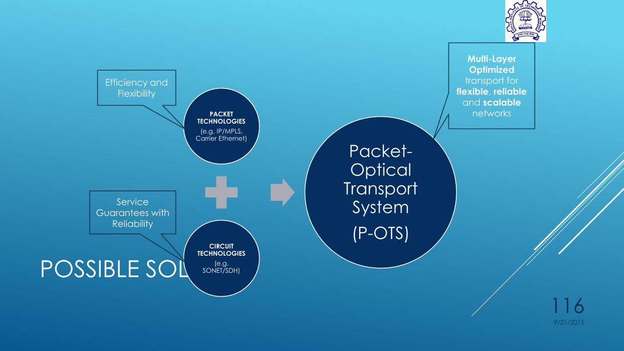
POSSIBLE SOLUTION
9/21/2015
116
PACKET TECHNOLOGIES
(e.g. IP/MPLS, Carrier Ethernet)
CIRCUIT TECHNOLOGIES
(e.g. SONET/SDH)
Packet-Optical
Transport System
(P-OTS)
Efficiency and Flexibility
Service Guarantees with
Reliability
Multi-Layer Optimized
transport for
flexible, reliable and scalable
networks
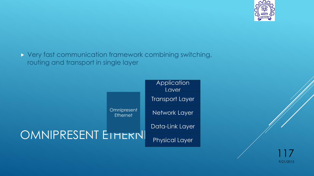
OMNIPRESENT ETHERNET (OE)
Very fast communication framework combining switching, routing and transport in single layer
9/21/2015
117
Application
Layer
Transport Layer
Network Layer
Data-Link Layer
Physical Layer
TCP/UDP
IP
Ethernet
OmnipresentEthernet
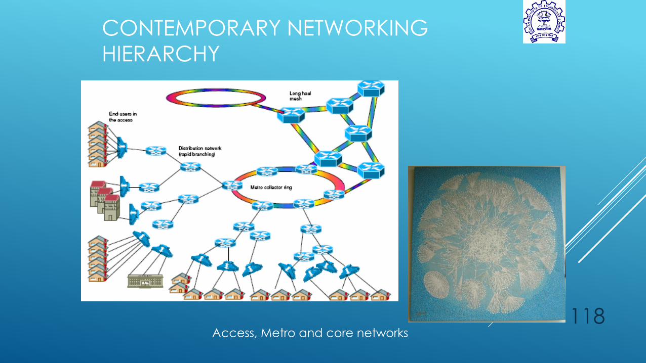
CONTEMPORARY NETWORKING
HIERARCHY
118Access, Metro and core networks

119
Formulate physical network into a logical hierarchical tree
Simplify the network into a fractal binary tree
Binary Routing
Packet switching based on the bit value correspondingto the node – ‘0’ indicates right-ward movement while a‘1’ indicates left-ward movement
Advantages:
Simple lookup
Energy efficient
Source routing
Cost, cost, cost!!!!!
A
B DE
F
GHI
JK
L
M
N
O
Fig. 1a. Physical topology of the network.
A
B DE
F
GHI
J
K
L
M
N
O
1
01
1
0
1

EXAMPLE OF CONVERSION TO A
BINARY TREE
120
Laptop computer
Workstation
Mac Classic
IBM Compatible
Laptop computer
IBM Compatible
Gateway
Campus node
(large switch)
MTU -
switch
Campus node
(large switch)
MTU -
switch
Virtual (dummy) node
created
0000
000
0001
001
000
01
010
0110110
0111
01100
1
10
100
1011000
1001
10010 10011
100100100111
11111
1110
1111
11110111100
11111111111
110
11001101 11011
110111
Source
Destination
A
B
C
D
E
F
H
IJ
K
L
M
G
N
O
10
10110
1011001101011001101001
101100110100101
Ni
NjNq
Nr
121
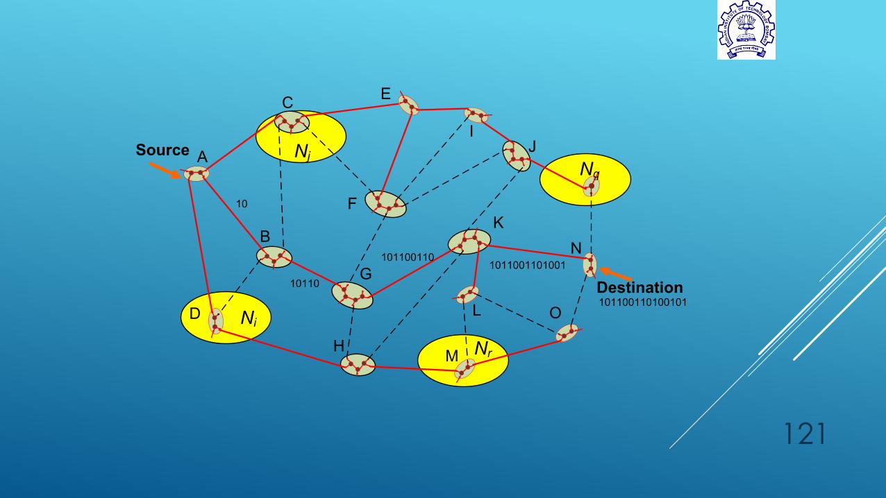
Source
Destination
A
B
C
D
E
F
H
IJ
K
L
M
G
N
O
10
10110
1011001101011001101001
101100110100101
Ni
NjNq
Nr

CONCEPT OF OE
Creating Virtual Topology
Binary Routing
9/21/2015
122
Network Graph
Logical Tree
Logical Binary Tree
Binary
Routing
Source
Routing
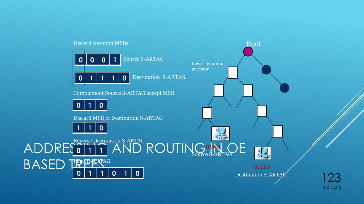
ADDRESSING AND ROUTING IN OE
BASED TREES
9/21/2015
123
0 0 0 1
Root
Lowest common ancestor
0001Source S-ARTAG
Destination S-ARTAG
00
11
00
11
11
00
01110
0 1 1 1 0
0 1 0
1 1 0
Source S-ARTAG
Complement Source S-ARTAG except MSB
Discard MSB of Destination S-ARTAG
Reverse Destination S-ARTAG
0 1 1
0 1 1 0 1 0
Final R-ARTAG
Destination S-ARTAG
Discard common MSBs

Ethernet
frame
with data Ethernet
header
dat
a
Ethernet data
mapped onto
OE packet –
Ethernet
header used
for L2
protocol.
Omnipresent Ethernet another avatar of MPLS and SDNsIdentifier Binary Tag
IP address IPV4
010001001
IP address IPV6
100101010
MAC 1010
Port 111010
S/CTAG 00101010101

UNICAST PACKET FLOW
9/21/2015
126
Output Port
Decoder
OE Framing/
De-framing
Ra
teLi
mite
r
Route
Calculator
TELL Table
Inp
ut
Po
rt L
og
ic
Write
State
Machine
Memory Arbiter
QDR II+ QDR II+ QDR II+ QDR II+
Read
State
Machine
Memory
Mgmt.
Unit
Frame Buffer
Contention Resolution Logic
(Port 2)
Port 1
Port 2
Port N-1
Output
Port 0
Output
Port 1
Output
Port 2
Output
Port N-1
Switch Fabric
Port Control Logic and Multicast Handler

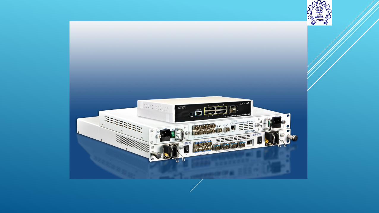
THE CESR HARDWARE
Fig 1. The Carrier Ethernet Switch Router(CESR) hardware
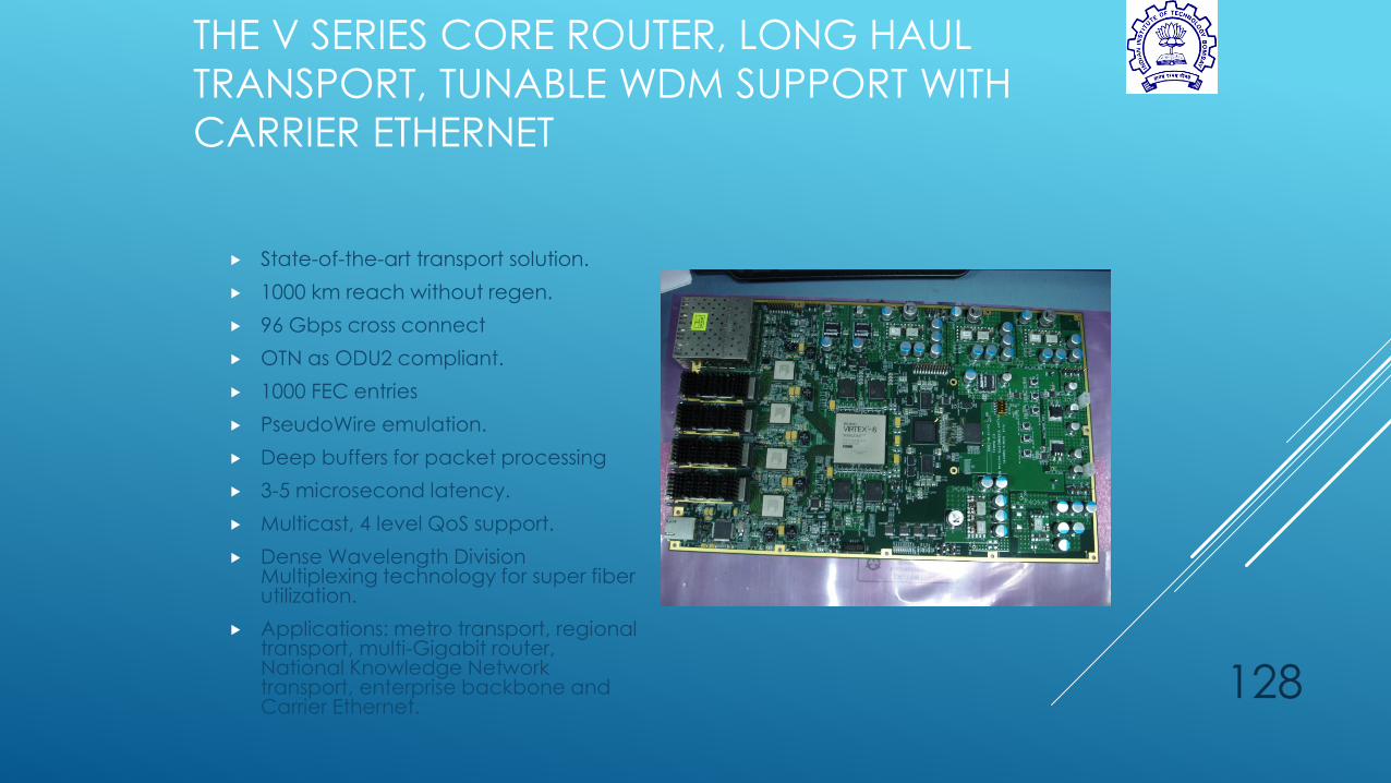
THE V SERIES CORE ROUTER, LONG HAUL
TRANSPORT, TUNABLE WDM SUPPORT WITH
CARRIER ETHERNET
State-of-the-art transport solution.
1000 km reach without regen.
96 Gbps cross connect
OTN as ODU2 compliant.
1000 FEC entries
PseudoWire emulation.
Deep buffers for packet processing
3-5 microsecond latency.
Multicast, 4 level QoS support.
Dense Wavelength Division Multiplexing technology for super fiber utilization.
Applications: metro transport, regional transport, multi-Gigabit router, National Knowledge Network transport, enterprise backbone and Carrier Ethernet.
128

STATISTICSO1000 –
LX240T (IPv4)
O1000 –
LX365T (IPv6)
O1010 –
LX365T
O100 – LX150T
FPGA device Utilization 92% 67% 71% 71%
BRAM Utilization 59% 61% 74% 74%
Lines of code (VHDL) 1,28,405* 1,28,405* 68,302** 68,302**
Lines of code (NMS) 16,142 16,142 16,142 16,142
Lines of code Web based
NMS
50,000 + 50,000 + 50,000 + 50,000 +
PCB stats
R ~ 500,
C ~ 1000
R ~ 500,
C ~ 1000
R ~ 300,
C ~ 700
R ~ 700,
C ~ 2000
135 different
components
135 different
components
107 different
components
176 different
components
Total components
1500+ 1500+ 2200+ 850
*O1000 code statistics includes test code**O100 and O1010 code statistics exclude common files from O1000.
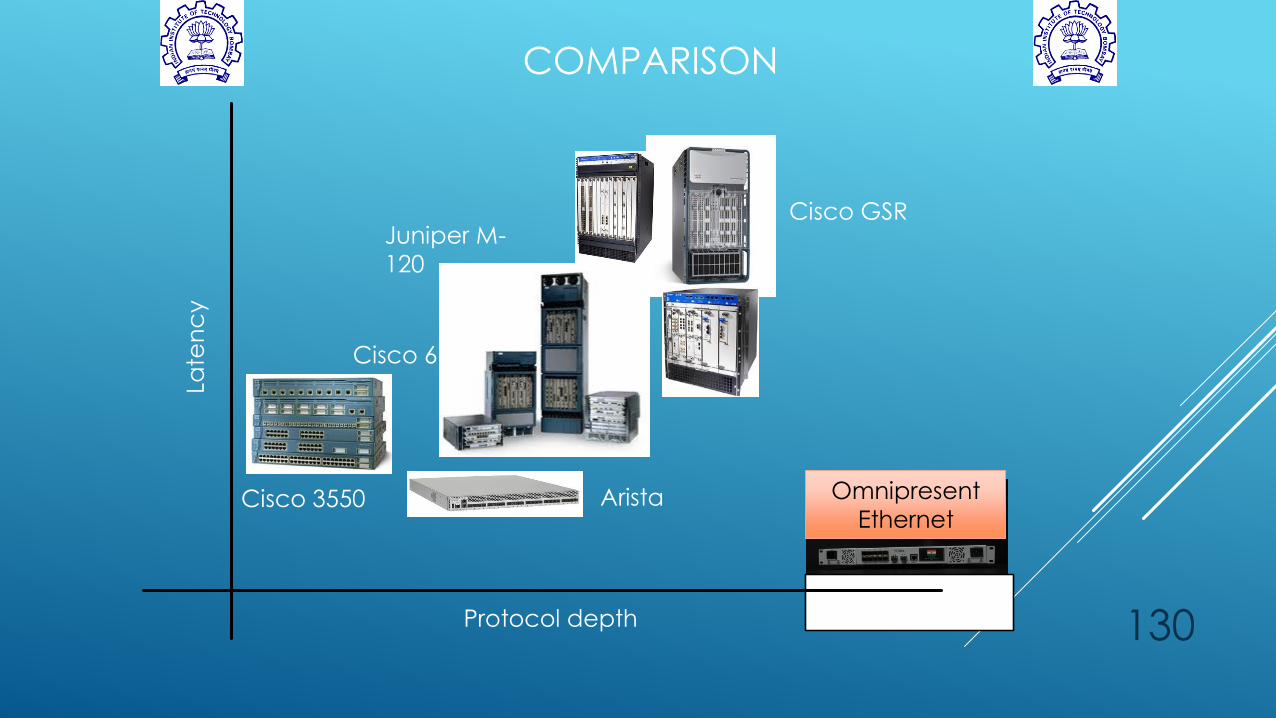
COMPARISON
130Protocol depth
Late
nc
y
Cisco 3550
Juniper M-
120
Cisco GSR
Cisco 6700
Arista Omnipresent
Ethernet

CESRS DEVELOPED
Port-to-port latency = 1.2 microsecond
OTN support for long reach without 3R
DWDM optics supported
E-LINE, E-LAN service support for MAC,IPv4,IPv6, CTAG, STAG, port based identifiers
9/21/2015
131

EXPERIMENTAL TEST-BED DESCRIPTION
RailTel Western Region Network
22 nodes
23 links
9/21/2015
132
Working Path
Protection Path

TEST-BED PHOTOGRAPH
9/21/2015
133
JDSU MTS-6000
Client Node-1
Fiber Links
NMS
JDSU MTS-6000
Client Node-2
CESR 2
CESR 1