rotor vortex filaments: living on the slipstream's edge · pdf filerotor vortex...
TRANSCRIPT

NASA Technical Memorandum 110431
Rotor Vortex Filaments: Livingon the Slipstream's Edge
Larry A. Young, Ames Research Center, Moffett Field, California
January 1997
National Aeronautics andSpace Administration
Ames Research CenterMoffett Field, California 94035-1000
https://ntrs.nasa.gov/search.jsp?R=19970011043 2018-05-26T12:30:40+00:00Z


NOMENCLATURE
CT
dS
dV
gr
I(x)
N
n
P
PQSV
PUNV
R
rc
ro
u
U
VT
Rotor thrust coefficient
Elemental surface (m 2)
Elemental volume (m 3)
Gravity induced body forces per unit mass (m/sec 2)
Impulsive force function; x is the argument. Quantifies impulsive force due to vortex-
driven flow crossing the slipstream shear layer.
Number of rotor blades
Normal vector to control surface, used in vorticity conservation surface integrals
(positive radially outward)
Static pressure (N/m 2)
Static pressure component due to quasi-steady vortex-dominated flow (N/m 2)
Static pressure component due to flow with unsteady, non-vortex-driven velocity
components (dominated instead by large radial and not tangential velocities
(N/m 2)
Rotor radius (m)
Radial coordinate, referenced to the vortex core center (m)
Vortex core radius initial value, at t = 0 (m)
Outer radial limit of derived stream function solution, where mass transfer across
slipstream shear layer ceases (m)
Time (sec)
Velocity component normal to the vortex core control volume surface element
(positive radially outward)
Rotor axial-flight freestream velocity (m/sec)
Rotor tip speed (rrdsec)
Mean inflow velocity at rotor disk plane (m/sec)
iii
vi
Vr
Vz
v0
Z
8(x)
8"(x)
1'
V
f2
P
0
co
Rotor slipstream velocity in the far-wake, from momentum theory, v i = 2v (m/sec)
Radial velocity component, with respect to local cylindrical coordinate system with
origin at vortex core center (m/sec)
Axial velocity component, with respect to local cylindrical coordinate system with
origin at vortex core center, flow along filament length (m/sec)
Tangential velocity component, with respect to local cylindrical coordinate system
with origin at vortex center (m/sec)
Axial coordinate, along axis of vortex filament, with respect to local cylindrical
coordinate system with origin at vortex center (m)
Dirac ("delta") function; x is the argument
Derivative of Dirac ("delta") function, 8"(x) = d(8(x))/dx
Vortex filament circulation initial value, at t = 0 (m2/sec)
Kinematic viscosity (m2/sec)
Rotor rotational speed (radians/sec)
Freestream density (kg/m 3)
Polar coordinate, with respect to local cylindrical coordinate system, referenced to the
vortex core center and the shear layer/slipstream boundary (radians)
Stream function (m2/sec)
Localized three-dimensional contribution to the vortex tangential velocity and
vorticity, accounts for "line-sink" Vz flow at the shear layer boundary (m2/sec)
I?"Mean" stream function scaler value, function of r only, where _ - (_ + _,)de,
(m2/sec)
Wake age (degrees)
Net required wake age for vortex filament decay/collapse (degrees)
Flow vorticity
iv
ROTOR VORTEX FILAMENTS: LIVING ON THE SLIPSTREAM'S EDGE
Larry A. Young
Ames Research Center
SUMMARY
The purpose of this paper is to gain a better understanding of rotor wake evolution in hover and
axial flow by deriving an analytical solution for the time dependent behavior of vortex filament
circulation and core size. This solution is applicable only for vortex filaments in the rotor far-wake.
A primarily inviscid vortex/shear layer interaction (where the slipstream boundary is modeled as
a shear layer) has been identified in this analytical treatment. This vortex/shear layer interaction
results in decreasing vortex filament circulation and core size with time. The inviscid vortex/shear
layer interaction is shown, in a first-order treatment, to be of greater magnitude than viscous diffu-
sion effects. The rate of contraction, and ultimate collapse, of the vortex filament core is found to be
directly proportional to the rotor inflow velocity.
This new insight into vortex filament decay promises to help reconcile several disparate observations
made in the literature and will, hopefully, promote new advances in theoretical modeling of rotor
wakes.
INTRODUCTION
Even the most sophisticated of rotor free wake analyses neglect the decay of vortex filaments in their
wake modeling. The assumption of constant vortex circulation and core size as adopted in free-wake
analyses is too simplistic. And yet, to date, there is no new theoretical approach to replace this
constant circulation and core size assumption. This dichotomy is noted in reference 1. Most insights
into vortex filament decay have their roots in fixed-wing aerodynamics. But, as the author will
contend in this paper, application of these fixed-wing observations to rotorcraft is unjustified and
ultimately leads to erroneous conclusions.
What is not in dispute throughout the rotorcraft literature is that within three to five blade passageswell-defined vortex filament structures can not be observed by means of any flow visualization
technique. The analytical/computational treatment of the far-wake as evolving into an "'ultimate"
wake is, therefore, conceptually flawed. What has been the conventional wisdom, as regards this
observed vortex filament decay in the far-wake, is that viscous diffusion effects are responsible for
the process. Various turbulent vortex models, derived from fixed-wing analytical work, have been
ad hoc modified and applied to attempt to account for, or match, the observed rotary-wing vortex

filament decay process. There has not been a fundamental re-examination of the vortex
dynamics/fluid mechanics for rotor trailed vortices.
Other than qualitative flow visualization work, there is mixed empirical evidence for the time-
dependent behavior of rotary-wing vortex filament circulation and core size. Most measurements
have been made near, or before, the first blade passage. Correspondingly, these measurements have
shown little wake age dependence of circulation and core size. Recent rotary-wing experimental
observations, encompassing a greater range of wage ages than previously studied, are starting to
appear in the literature. For example, one such study (A. Wadcock, Measurement of Vortex Strength
and Core Diameter for a Model Tiltrotor, a soon to be published NASA CR) has presented hot-wire
anemometry results that suggest that vortex circulation and core size both appear to decrease with
wake age. This observation is counter to expectations based on the flow behavior of fixed-wing
trailed vortices. However, an attempt to use the wide-field shadowgraph technique, reference 2, to
measure rotor vortex core size as a function of wake age appeared to show the opposite trend from
the Wadcock study. Reference 2 results implied that there was core size growth with wake age.
Interestingly enough, both the Wadcock study and the reference 2 work conducted their vortex core
size measurements with the same rotor/test-stand, in two different test entries. Both studies, though
promising in their technique and initial results, should be considered as very preliminary bodies ofwork.
Another noteworthy set of studies for vortex circulation and core size trends with wake age is the
laser velocimetry work of references 3-5. However, though the authors of these works have made
impressive progress in their measurement techniques, they have, to date, relied upon rather simplis-
tic rotor systems that are not representative of actual aircraft. In particular, they obtained their test
results for one-bladed, low tip speed rotors. As will be discussed later in the paper, the geometry and
operating condition of rotor test models will have a substantial impact on the observed vortex circu-
lation and core size trends. More systematic work using realistic scaled rotor models is required
before empirical observations provide definitive answers to the rotary-wing vortex decay process.
What is needed, more importantly though, is a fresh approach to the problem by reconsidering the
fundamental differences between a trailed vortex filament from a fixed- and rotary-wing. The chief
difference between the two types of trailed vortices, besides the helical geometry of the rotor vortex
filament versus the rectilinear fixed-wing vortex, is that the rotor vortex is not surrounded by a
uniform flow field as is the fixed-wing trailed vortex but is instead embedded in a shear layer.
It is this flow feature, and the associated singular fluid mechanics, of a vortex in a shear layer that
governs the decay process of a rotor trailed vortex filament. This area of investigation (vortex/shear
layer interactions) has received very little analytical/computational work even though it would seem
to be a fundamental type of fluid flow problem deserving considerable attention.
This paper addresses the above noted oversight by developing an analytical model of vortex filament
decay that accounts for vortex/shear layer interactions and is applicable to hover and axial-flightrotor wakes.
This work is dedicated to the memory of Clara Jeannette McClelland Springer.
2

DESCRIPTION OF AN IDEALIZED FLOW PROBLEM AND
ITS RELATIONSHIP TO ROTOR WAKES
Figure 1 shows a vortex filament in the far wake region of a rotor slipstream. Sufficiently down-
stream in the far-wake, the rotor slipstream flow is no longer accelerating and the boundary is no
longer contracting. Further, the roll-up of vortex sheets inside the rotor wake has been completed
and all vorticity is encompassed in the rotor trailed tip vortices. It is in the rotor far-wake that a
number of simplifying assumptions can be made about the slipstream flow field, resulting in a"idealization" of the localized environment about a trailed vortex. First of all, the influence of wake
contraction and nonuniform wake velocity profile will be neglected in this study. Further, the vortex
filament helical angle and curvature can be assumed to be small and the flow problem can be treated
as quasi-two-dimensional. Finally, the slipstream flow field is assumed uniform and the slipstream
boundary is modeled as a discontinuous shear layer.
+
Rotor Disk
Vortex Filament,
refer to Figure 2a-cfor cross-sectional
close-up view
v,1
Slipstream Boundary
Figure 1. Vortex filament in the far-wake of a rotor slipstream.
Figures 2(a--c) illustrate the vortex filament fluid mechanics (in a two-dimensional plane) at the
slipstream boundary. Helmholtz's Law requires that a vortex filament generated at the rotor disk
accelerates to an equilibrium velocity of U + vi/2 along the slipstream boundary. The local cylin-
drical coordinate system choosen for the idealized flow problem tracks along with an isolated vortex
core center at this velocity of U + vi/2. Consequently, the velocity inside the shear layer is +vi/2,
while outside it the velocity is -vi/2. This shear layer in the idealized flow problem is prescribed,
time-invariant, and discontinuous.

_ Slipstream Bounda/____Rankine
Vortex
+vii 2
Figure 2a - Radial velocity of unitvolume of fluid just prior to
crossing slipstream boundary, whilewithin rotor wake.
F - -IC3
Figure 2b - Unit volume of fluidsubjected to impulsive force whencrossing slipstream boundary.
Figure 2c - Radial velocity of unitvolume of fluid just after crossingslipstream boundary; impulsive
force results in momentum change.
Figure 2. Problem description.
4
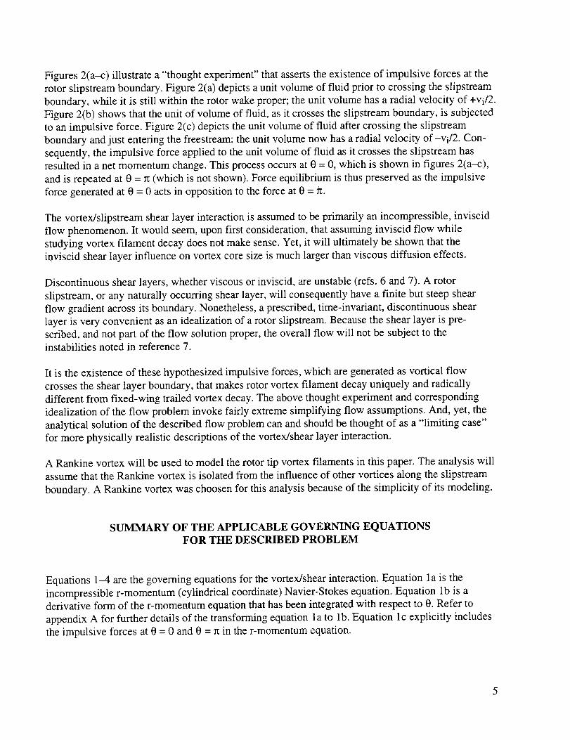
Figures 2(a-c) illustrate a "thought experiment" that asserts the existence of impulsive forces at the
rotor slipstream boundary. Figure 2(a) depicts a unit volume of fluid prior to crossing the slipstream
boundary, while it is still within the rotor wake proper; the unit volume has a radial velocity of +vi/2.
Figure 2(b) shows that the unit of volume of fluid, as it crosses the slipstream boundary, is subjected
to an impulsive force. Figure 2(c) depicts the unit volume of fluid after crossing the slipstream
boundary and just entering the freestream; the unit volume now has a radial velocity of-vi/2. Con-
sequently, the impulsive force applied to the unit volume of fluid as it crosses the slipstream has
resulted in a net momentum change. This process occurs at 0 = 0, which is shown in figures 2(a-c),
and is repeated at 0 = n (which is not shown). Force equilibrium is thus preserved as the impulsive
force generated at 0 = 0 acts in opposition to the force at 0 = _t.
The vortex/slipstream shear layer interaction is assumed to be primarily an incompressible, inviscid
flow phenomenon. It would seem, upon first consideration, that assuming inviscid flow while
studying vortex filament decay does not make sense. Yet, it will ultimately be shown that the
inviscid shear layer influence on vortex core size is much larger than viscous diffusion effects.
Discontinuous shear layers, whether viscous or inviscid, are unstable (refs. 6 and 7). A rotor
slipstream, or any naturally occurring shear layer, will consequently have a finite but steep shear
flow gradient across its boundary. Nonetheless, a prescribed, time-invariant, discontinuous shear
layer is very convenient as an idealization of a rotor slipstream. Because the shear layer is pre-
scribed, and not part of the flow solution proper, the overall flow will not be subject to the
instabilities noted in reference 7.
It is the existence of these hypothesized impulsive forces, which are generated as vortical flow
crosses the shear layer boundary, that makes rotor vortex filament decay uniquely and radically
different from fixed-wing trailed vortex decay. The above thought experiment and corresponding
idealization of the flow problem invoke fairly extreme simplifying flow assumptions. And, yet, the
analytical solution of the described flow problem can and should be thought of as a "limiting case"
for more physically realistic descriptions of the vortex/shear layer interaction.
A Rankine vortex will be used to model the rotor tip vortex filaments in this paper. The analysis will
assume that the Rankine vortex is isolated from the influence of other vortices along the slipstream
boundary. A Rankine vortex was choosen for this analysis because of the simplicity of its modeling.
SUMMARY OF THE APPLICABLE GOVERNING EQUATIONS
FOR THE DESCRIBED PROBLEM
Equations 1--4 are the governing equations for the vortex/shear interaction. Equation l a is the
incompressible r-momentum (cylindrical coordinate) Navier-Stokes equation. Equation lb is a
derivative form of the r-momentum equation that has been integrated with respect to 0. Refer to
appendix A for further details of the transforming equation la to lb. Equation lc explicitly includes
the impulsive forces at 0 = 0 and 0 = 7t in the r-momentum equation.
5

0vr 0vr vo 0vr 0vr v_ ( v r 2 0v0" ]
+ -- _ + v z - F + v_V2Vr r2 r 2 000t Vr Or r 00 0z r )
$
Vr Or r Oe J Or e=O,rc0(2_ dO)+
(la-b)
where F in equation 1a is given by
F = __1 OF' + gr + 17_ {I[8(0) + 5(0- rt)]} (lc)p Or p or-
The key modeling assumptions employed in equation lb are: the flow is inviscid; the flow is quasi-
two-dimensional such that 0Vr/0Z = 0v0/0z = 0Vz/0Z = 0, except that 0Vz/0Z = (1/Vz)(0Vz/0t) ¢ 0
when 0 = nTt, for n = 0,1,2 .... ; the radial pressure gradient is primarily due to the vortex tangential
flow pv_/r = 0P/0r for 0 _e nrc; the impulsive force can be related to the net momentum change
across the discontinuous shear layer by
1 O {Ii[5(0) + 8(0_ rt)ldO} = _2vi Ov0p Or Or 0=0,re
Equation 2a is an identity that follows straightforwardly from differential calculus. Definition of the
two new parameters, _t and gt., eliminates 0 from the identity. Refer to appendix B for additional
details as to the definition and application of equations 2a-b.
r=rc/ ) r:rc (2a)
where
tg - Ion(V + v.)d0 (2b)
Note that in equation 2b and in subsequent use in this paper, gt. is the localized three-dimensional
contribution to the vortex tangential velocity and vorticity, that accounts for nonzero Vz flow at the
shear layer boundary.
Equation 3a is the general form of the vorticity conservation equation. Equation 3b is the derivative
form of the conservation equation for a control volume about the vortex core boundary. This
6
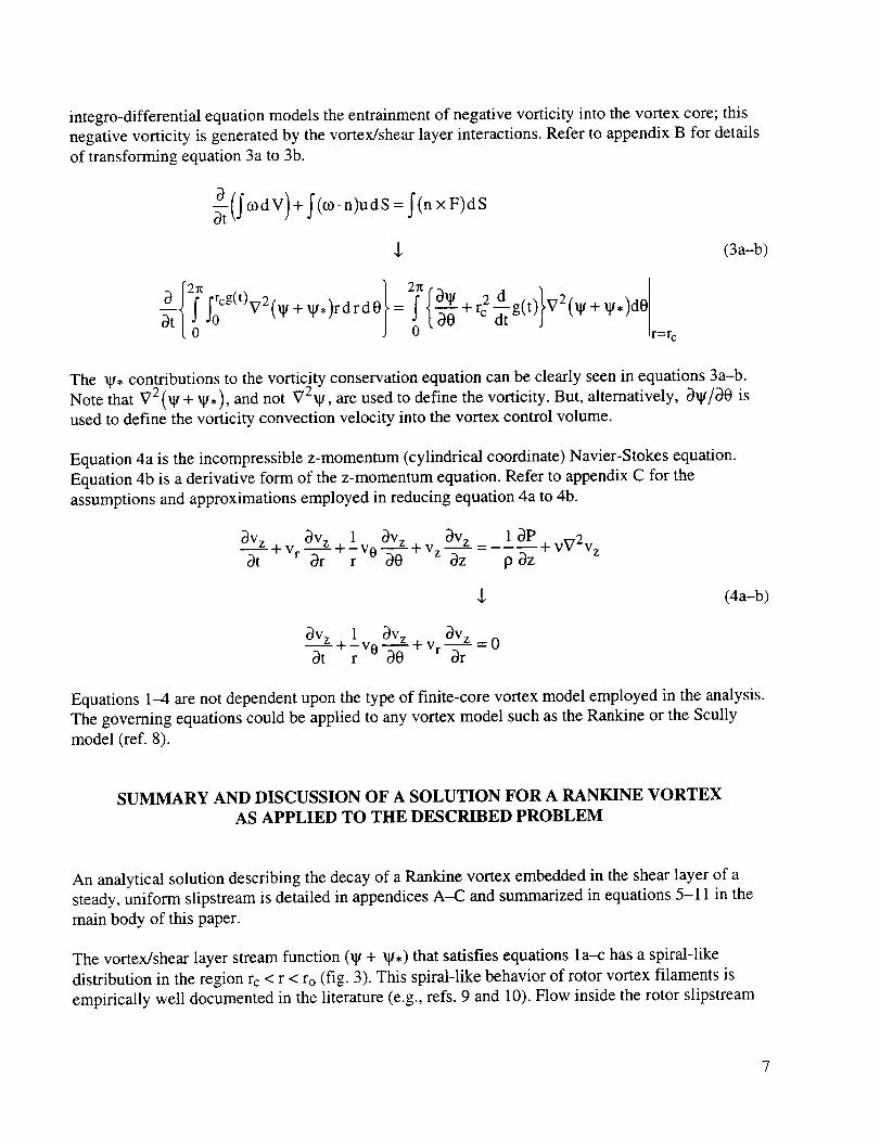
integro-differential equation models the entrainment of negative vorticity into the vortex core; this
negative vorticity is generated by the vortex/shear layer interactions. Refer to appendix B for details
of transforming equation 3a to 3b.
_(_ cod V)+ f(o)-n)udS = I(n x F)dS
,[, (3a-b)
a rrcg(t) 2, _t,)rdrdO
atl Jo v= 2j'n{-_-0 + r2 d g(t)}V2 (_ + _,)dO
0 r=r c
The _, contributions to the vorticity conservation equation can be clearly seen in equations 3a-b.
Note that V2(_ + _.), and not V2_, are used to define the vorticity. But, alternatively, O_I//a0 is
used to define the vorticity convection velocity into the vortex control volume.
Equation 4a is the incompressible z-momentum (cylindrical coordinate) Navier-Stokes equation.
Equation 4b is a derivative form of the z-momentum equation. Refer to appendix C for the
assumptions and approximations employed in reducing equation 4a to 4b.
av z 1 aVz+ v av z laPavz + --+-v 0 _- + vg2vzat Vr Dr r 20 z az paz
,l, (4a-b)
av z 1 av z _v zF +Vr--=0
at r v0 "_- Dr
Equations 1-4 are not dependent upon the type of finite-core vortex model employed in the analysis.
The governing equations could be applied to any vortex model such as the Rankine or the Scully
model (ref. 8).
SUMMARY AND DISCUSSION OF A SOLUTION FOR A RANKINE VORTEX
AS APPLIED TO THE DESCRIBED PROBLEM
An analytical solution describing the decay of a Rankine vortex embedded in the shear layer of a
steady, uniform slipstream is detailed in appendices A-C and summarized in equations 5-11 in the
main body of this paper.
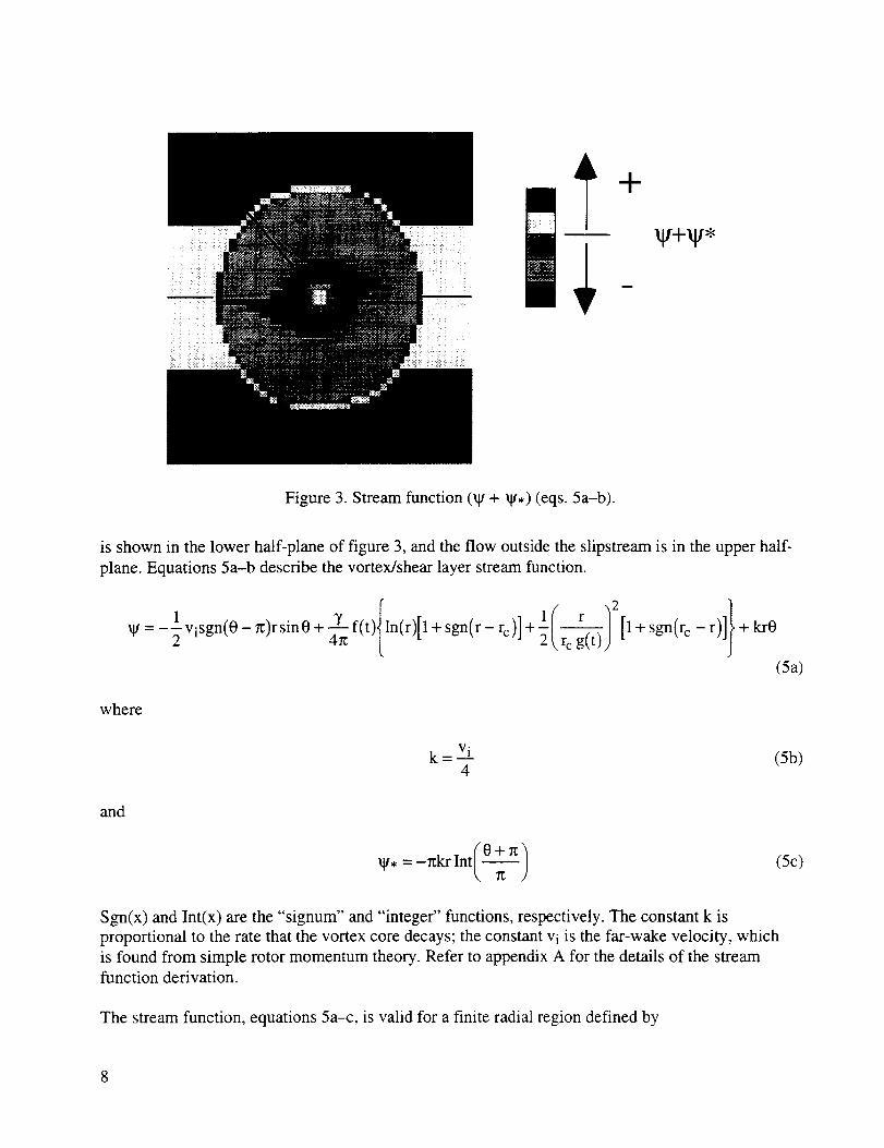
The vortex/shear layer stream function (_ + gt.) that satisfies equations la--c has a spiral-like
distribution in the region rc < r < ro (fig. 3). This spiral-like behavior of rotor vortex filaments is
empirically well documented in the literature (e.g., refs. 9 and 10). Flow inside the rotor slipstream
-t-
gt+gt,
Figure 3. Stream function (_ + _.) (eqs. 5a-b).
is shown in the lower half-plane of figure 3, and the flow outside the slipstream is in the upper half-
plane. Equations 5a-b describe the vortex/shear layer stream function.
1" _ i / r/211 + sgn(rc _ r)l}+ k_OIp'= -1 visgn(0- _)rsin0 + _ f(t)lln(r)[1 + sgn(r - rc)],2 _r c g(t))
(Sa)
where
k=V_L4
(5b)
and
(5c)
Sgn(x) and Int(x) are the "'signum" and "integer" functions, respectively. The constant k is
proportional to the rate that the vortex core decays; the constant vi is the far-wake velocity, which
is found from simple rotor momentum theory. Refer to appendix A for the details of the stream
function derivation.
The stream function, equations 5a-c, is valid for a finite radial region defined by

rcg(t)< r < 2@kf(t)
The "finiteness" of the applicable flow region of the stream function is very important. It
circumvents the prediction of physically unrealistic flow behavior far from the vortex core by
confirming that the vortex/shear layer interaction is a "localized" phenomenon.
The stream function, as written in equations 5a--c, is also subject to the flow constraint
(0gtSlipstream Flow/0r)/(0XgVortex/0r) > 0
This flow constraint confirms that the stream function has been written to conform to the flow
representative of rotary-wing slipstreams and vortices. Alternatively, bluff body wakes and shedvortices do not conform to this flow constraint. This issue will be discussed further later in the paper.
A consequence of the derived stream function, equations 5a-b, is that negative vorticity is generated
by the vortex/shear interaction (see eq. 6).
co=-1 k{0- rtlnt(_-)} +/tk B'(0- rt)+r vi {2fi(0- rc)c°s 0+r 5'(0-rt) sin 0}
for r > rcg(t ) (6)
Equation 6 demonstrates that just as impulsive forces exist for a vortex embedded in a discontinuous
shear layer, so does impulsive changes in vorticity. Most importantly, negative vorticity is created
at the shear layer and will be shown to be convected/entrained into the vortex core. This result,
equation 6, is crucial for the discussion that follows for the time-dependent behavior of the vortexfilament circulation and core size--i.e., the decay process itself. Refer to appendix B for details to
the vorticity expression, equation 6, derivation.
The velocity and stream-function relationships used in this paper are subtly different from their
conventional definition. They have been modified to account for quasi-two-dimensional flow. Quasi-
two-dimensional flow has been defined in this paper as allowing localized, nonzero, time-dependent
axial flow (v z ¢ 0 at 0 = 0 and 0 = r_, whereas v z = 0 for 0 _: nrt where n = 0,1,2 .... ) along the shear
layer boundary. The velocity and stream function definitions have been modified such that now
v 0 = +O(W + _g,)/Dr and v r = -(l/r)(O_g/O0). The tangential velocity expression has picked up anadditional stream function term, tg,, as compared to its conventional definition.
The consequence of this quasi-two-dimensional flow revision to the stream function and velocity
definition, when applied to the vortex/shear layer interaction problem, is that a constant radial flow
into the vortex center is predicted, as well as an asymmetric tangential velocity distribution (see
eqs. 7-8). The tangential velocity asymmetry can be seen in figure 4. The velocity profile shown
in figure 4 is along the slipstream boundary (0 = 0 and 0 = 7t). Therefore, the asymmetry shown in
9

Tangential Velocity
!
Radial Coordinate, r/rc
Figure 4. Decay of vortices on a rotor slipstream boundary.
figure 4 is distinct from the asymmetry encountered/expected when crossing the slipstream boundary
(i.e., 0 = n/2 or 3n/2).
v0=--2 v,- sgn(0- n)sin0 + f(t) 1 + sgn(r- rc)]-_ r2 g(t)2 [1 + sgn(rc - r )
+ k(O - rtlnt(-_)]
(7)
1
Vr = _-v i sgn(O - n)cosO - k (8)
Derivation of radial and tangential velocity analytical expressions follow directly from the derived
stream function, equations 5a-b.
Radial flow and vorticity entrainment into the vortex core causes the vortex circulation to be time
dependent. Vortex circulation is found to be a decreasing function of time and wake age. Refer to
equations 9a-b and figure 5.
10

Circulation = "if(t) (9a)
where
(9b)
g(t), f(t)
1 _%._re Radius
0.5
0
time, t
Figure 5. Vortex circulation and core size as a function of time (eqs. 9 and 10).
y and rc are the initial values, respectively, of vortex circulation and vortex core radius. The function
g(t) is defined in equation 10b. The function f(t) encompasses the time dependency of vortex circula-
tion. The function g(t) reflects the time dependency of the vortex core size. Refer to appendix B
for the details of the derivation of the above analytical expression for the vortex circulation decay.
The rate of decay of circulation can be seen to be directly proportional to rotor inflow velocity.
Identification of a potential flow mechanism that results in decreasing circulation is quite surprising.
Even more surprising is the analytical result for the time dependence of the vortex core size. Core
size is also found to decrease with time and wake age. Refer to equations 10a-b and figure 5.
Core Radius = rcg(t ) (lOa)
where
Tf(t) +/l:2krcg(t) = rt2krc + y- (2vik + g2k2 )t (lOb)
rc is the initial value for the vortex core radius; equation 5b provides the value of the constant, k.
Equations 9b and 10b are a nonlinear, simultaneous set of equations that are iteratively solved for
fit) and g(t) for each time, t. Refer to appendix B for the details of the derivation of the solution of
the vortex circulation and core size time dependent behavior.
11

The prediction of vortex core size contraction is contrary to conventional thinking, which is based in
large part upon observations made from rotary-wing flow visualization studies. This discrepancy
will be discussed further later in this paper. But a key consideration in interpretation of rotor wake
flow visualization results is the assumption of the relative magnitude of axial flow, Vz, along the
vortex filament length.
Work from this paper (eqs. I 1a-b) predicts large vortex filament axial velocities along the shear
layer boundary.
v z = enkS(O-nn)t/r for t << A_gw/_ (1 la)
Vz ___ AeSgn(0-n)r sin 0 for t _ oo (1 lb)
where
2
A =-2_TT _ln(VT2 + v2 ) - 2 ln(v)(llc)
Refer to appendix C for details of the axial flow solutions. Equation 1 la describes a "line-sink." A
portion of the mass flow crossing the slipstream boundary is redirected and convected axially along
the shear layer. Equation 1 la is a limiting case for more realistic shear layer models (where shear
layer gradients are steep but not discontinuous), and so equation 1 la suggests that axial velocities for
rotor tip vortices are large, but finite, and increase with time. Ultimately, at t ---) oo, the axial velocity
distribution of the asymptotic solution, equation 1 lb, suggests that a swirl distribution develops at
the slipstream boundary that counterbalances the swirl in the rotor slipstream from the blade root
vortex. Through equivalence of kinetic energy (an energy balance between the swirl from the blade-
root vortex versus that of the swirl induced from the trailed tip vortices), the constant A was defined,
equation 1 lc.
RE-EXAMINATION OF THE ANALYSIS ASSUMPTIONS IN LIGHT
OF THE DERIVED SOLUTION
It might be supposed that reliance on an inviscid analysis could result in invalid conclusions as to
vortex filament circulation and core size time-dependent behavior. A first-order examination of the
relative contraction and expansion rates of inviscid versus viscous effects will show that the inviscid
vortex/shear layer interaction dominates the fluid dynamics of rotor vortex filaments. Examining
more closely this assertion, i.e.,
12

at InviscidVortex/ShearLayerInteraction>>0rc
at ViscousTrailedVortexDecay(12a)
For t >> O,thepredictedinviscidvortexcorecontractionratewill becomparedto theviscousdiffusionrateof aLamb-Oseenlaminartrailedvortex(ref. 11).Or
(21)----)-- +at Inviscid Vortex/Shear Layer Interaction "_- _- i
(12b)
arc = 1.12_/-f_v
at Viscous Trailed Vortex Decay St(12c)
Using typical values for vi and v for equations 12a-c, the inviscid contraction rate is estimated as
being a couple of orders of magnitude greater than the laminar vortex core expansion rate. For
example, for A_w > 2 degrees (t >> 0), the laminar expansion rate is less than 0.1 foot per second.
But, for a hovering rotor, for 0.01 < CT < 0.015, which is typical of 1G thrust loaded rotors, the
predicted inviscid contraction rate is 50 to 60 feet per second. Some authors have suggested that the
contribution of turbulent viscosity to a trailed vortex diffusion rate may be as much as an order of
magnitude greater than the laminar estimate (see ref. 3). Nonetheless, if this supposition was provencorrect for rotor trailed vortices, the inviscid vortex/shear layer interaction contraction rate is still
greater than this inflated viscous diffusion rate estimate. Therefore, the inviscid flow assumption
employed in the beginning of this paper appears to be, ultimately, justifiable.
Another assumption employed in this paper's analysis that bears further scrutiny is that the radial
pressure gradient is dominated by quasi-steady vortical flow. That is, it has been assumed that
v___.__- 1 aP (13)
r P Dr
The static pressure can be separated into two components: a quasi-steady pressure component that
is dominated by the vortex flow and an unsteady, non-vortex-driven pressure component from the
vortex/shear layer interaction. That is: P = PQSV + PUNV. The implication of this observation is that
the above assumption (eq. 13) is equivalent to the assertion represented by equations 14a-c (for
0 _: 0 ¢rt where the pressure gradient contribution to the surface forces has been encapsulated in
the impulsive shear forces, I(5(0) + 5(0 - g)), which have been explicitly separated out):
>> OPLrNv (14a)
13

where the respective terms are
_PQsv _pV0=2 p(_v]23r r r_--_-r J
(14b)
_PuNV _Vr _Vr v0_Vr\ v0_Vr P (_/'](_2_ /
3r - -P_ + vr 3rj4 --->-p -r _0 r _0 r 2_,_rj_O 2) (14c)
Therefore, if equation 13 is true then, given equations 14a--c, the inequality constraint can be
re-written as
(15a)
Or, making substitutions from equation 5a-b,
"If(t) _-k{O-_Int(-_-_-)} >>0 (15b)2r_ r
Using typical values for fit), k, rc, and 7, the left hand side of the equation 15b inequality is found to
be quite large---one to two orders of magnitude greater than unity. Using the reference 2 values for
f(t), k, rc, and y, the ratio r/rc has to be greater than the value of 4.2 before the magnitude of the left
hand side of the inequality drops below unity. The stream function is valid to only ro/rc = 4.3. The
flow assumption represented by equation 13 thus appears valid.
Besides viscous flow effects, the distributed vorticity of real rotor vortices versus the concentrated
vorticity in the core of a Rankine vortex and the interactional influence of multiple rotor tip vortices
on each other will each tend to counterbalance the predicted core collapse. Additionally, the
influence of rotor slipstream acceleration on the vortex circulation and core size time dependent
behavior needs to be assessed in further work.
IMPLICATIONS OF THE VORTEX/SHEAR LAYER INTERACTION SOLUTION
WITH RESPECT TO OBSERVATIONS MADE IN THE LITERATURE
The predicted flow characteristics from this paper's work provide insight into several puzzling and
conflicting observations made in the literature regarding rotor wake behavior. Using the analytical
results from this paper, many of the these observations can at least be partially reconciled with each
other.
As noted earlier, a key empirical observation for rotor wakes, as reported innumerable times in the
literature, is that the rotor far wake loses, after three to five blade passages, its well-defined vortex
14
filamentstructure.Previously,thedecaymechanismfor thefar-waketrailedvortexfilamentshasbeenassumedto bedueto viscousdiffusionof thefilamentvorticity. Thispaperhaspromotedanalternatehypothesisandintepretationof thefilamentdecaymechanismand,further,hasderivedasolutionfor this inviscidvortex/shearlayerinteractionthatpredictsvortexcirculationandcoresizeto deceasewith time/wakeage.
But, asnotedearlier,thepredictionof vortexcoresizecontractionis contraryto conventionalthinking.Most experimentalstudiesreportedin the literatureonrotorwakesandvortexcoresizemeasurementshavereliedon smokeorparticleflow visualizationor,alternatively,velocitymeasurementsneartherotordiskplane.Thevortexcorehasbeenequated,or assumeddirectlyproportional,to observed"particlevoids" in vortexfilamentsfor seededrotorwakes.And, indeed,thesevortexfilamentparticlevoids,for rotorwakes,dogrow in sizewith time/wakeage.However,theauthorassertsthat smokeflow visualizationis aninvalid measureof vortexcoresize.
Thefascinatingflow visualizationphotographsof reference12aretheclearestillustrationthatthesmokeparticlevoid is not thesameasthevortexcore.In thereference12photographs,smokeflowvisualizationresults(i.e.,theparticlevoid) areobservedsimultaneouslywith fortuitousimagesofthevortexcoreasseenby meansof condensation.In manycases,thesmokeparticlevoid is muchgreaterin sizethanthevortexcore.
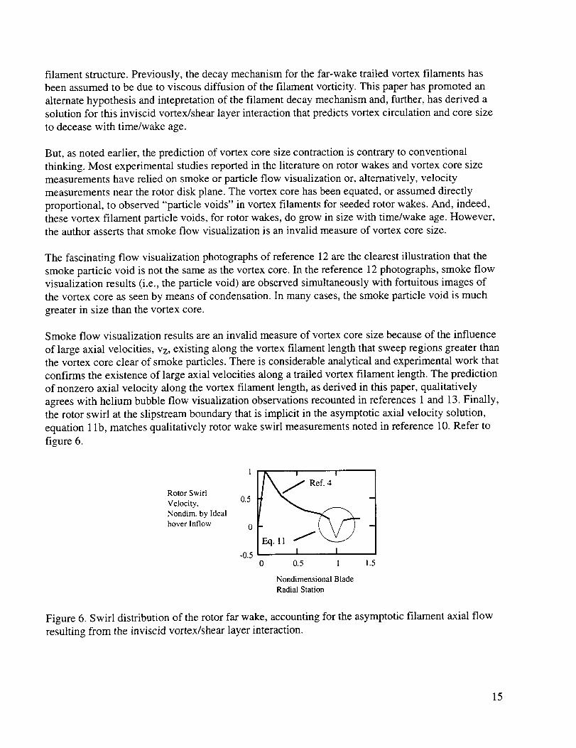
Smokeflow visualizationresultsarean invalid measureof vortexcoresizebecauseof theinfluenceof largeaxial velocities,Vz,existingalongthevortexfilamentlengththat sweepregionsgreaterthanthevortexcoreclearof smokeparticles.Thereis considerableanalyticalandexperimentalwork thatconfirmstheexistenceof largeaxialvelocitiesalongatrailedvortexfilamentlength.Thepredictionof nonzeroaxial velocity alongthevortexfilamentlength,asderivedin thispaper,qualitativelyagreeswith heliumbubbleflow visualizationobservationsrecountedin references1and13.Finally,therotor swirl at theslipstreamboundarythatis implicit in theasymptoticaxialvelocity solution,equation1lb, matchesqualitativelyrotor wakeswirl measurementsnotedin reference10.Refertofigure6.
Rotor Swirl
Velocity,
Nondim. by Ideal
hover Inflow
0.5
-0.5
Ref. 4
u
Eq. ll _ -
I I0 0.5 1 1.5
Nondimensional Blade
Radial Station
Figure 6. Swirl distribution of the rotor far wake, accounting for the asymptotic filament axial flow
resulting from the inviscid vortex/shear layer interaction.
15

On the basis of both measurements and predictions, axial velocities are clearly of a magnitude to
invalidate the assumption that the particle void at the center of a vortex is representative of the
vortex core radius. The particle void as seen in smoke visualization work should asymptotically
approach the value of ro(0)--where ro(t ) = "/f(t)/2rt2k and so ro(0 ) = 7/2rt2k--rather than rcg(t).
This hypothesis can be tested in future studies by comparing predicted ro(0) values to particle void
trends. (Reference 13 is one of few studies in the literature to provide quantitative data of the particle
void size trends with wake age. Unfortunately, reference 13 did not examine large enough wake ages
for an asymptotic limit to be observed.) If the above hypothesis is true, i.e., the particle void is
proportional to the ro(0), the asymptotic wake age limit for particle void size will be dependent upon
tip speed and blade count for hovering rotors.
The apparent discrepancies in vortex core size trends between the work of A. Wadcock (Measure-
ment of Vortex Strength and Core Diameter for a Model Tiltrotor, a soon to be published NASA
CR) and the shadowgraph results of reference 2 can be commented on in light of the predictions
of this paper. The study by Wadcock made hot-wire anemometry measurements of v0 and was,
therefore, able to directly estimate core size. The shadowgraph results of the reference 2, on the
other hand, would tend to be biased towards a measure of the resultant velocity vector, i.e.,
2, and not just v0. Interestingly enough, smoke flow visualization and shadowgraph_jv 2 + v_ + v r
test results will both be adversely impacted as a measure of vortex core size by not being able to
account for non-negligible axial velocities, Vz, along the filament lengths.
The majority of research into rotor vortex circulation and core size trends with wake age have relied
upon small-scale, low thrust, and low tip speed rotors. Also, one-bladed rotors have often been tested
to keep the wake geometry as simple as possible. See references 3 and 13, for example. There is a
critical scaling issue, though, in the use of small-scale, low tip-speed rotors and one-bladed rotors for
studying vortex decay mechanisms and generalizing the results to rotors more representative of
flight hardware (refer to eq. 16).
AWw = I rt24 8/¢_rc _ + (2rt2 + 16(16)
where A_w is the net amount of wake age required for decay of rotary-wing vortex filaments. Refer
to appendix B for details of the derivation of equation 16. The derivation of this wake age expression
for vortex decay follows directly from the nonlinear expressions for the vortex core size and
circulation, equations 9a-b and 10a-b.
Examining equation 16 closely, the equation suggests that one-bladed rotor test results can
potentially provide misleading insights into vortex circulation and core size trends. The vortex
filament decay of the rotor studied by A. Wadcock (Measurement of Vortex Strength and Core
Diameter for a Model Tiltrotor, a soon to be published NASA CR)ia small-scale rotor but with
typical blade count and tip speeds for full-scale rotorcraft--is predicted to occur over roughly
A_w = 60-80 degrees. The reference 3 rotor (low tip speed and a single rotor blade) theoretically
takes five times longer to decay out, i.e., A_w = 300-400 degrees. Reference 3 identified a gradual
decrease in circulation with wake ages in the far wake region; mixed results were seen for the core
16
size trend--though the authors ultimately concluded that there was overall growth in core size with
time. Because of the intrinsically lower vortex decay rate for the reference 3 rotor, these results can
not be considered conclusive.
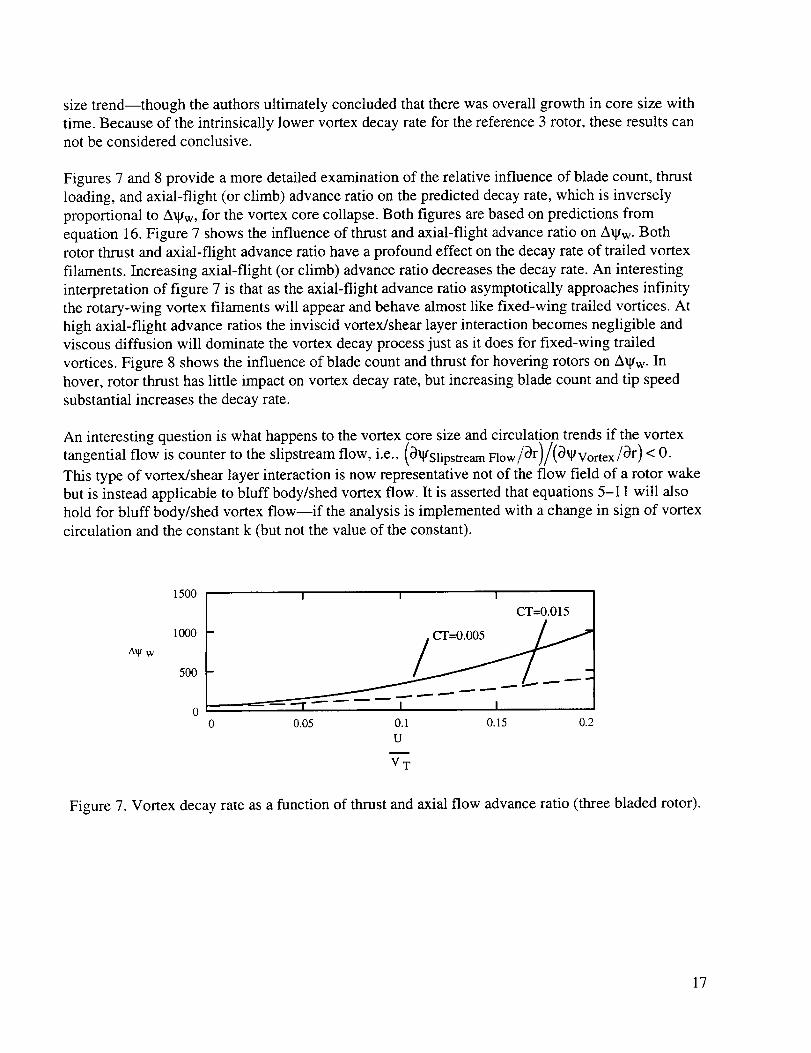
Figures 7 and 8 provide a more detailed examination of the relative influence of blade count, thrust
loading, and axial-flight (or climb) advance ratio on the predicted decay rate, which is inversely
proportional to A_w, for the vortex core collapse. Both figures are based on predictions from
equation 16. Figure 7 shows the influence of thrust and axial-flight advance ratio on A_w. Both
rotor thrust and axial-flight advance ratio have a profound effect on the decay rate of trailed vortex
filaments. Increasing axial-flight (or climb) advance ratio decreases the decay rate. An interesting
interpretation of figure 7 is that as the axial-flight advance ratio asymptotically approaches infinity
the rotary-wing vortex filaments will appear and behave almost like fixed-wing trailed vortices. At
high axial-flight advance ratios the inviscid vortex/shear layer interaction becomes negligible and
viscous diffusion will dominate the vortex decay process just as it does for fixed-wing trailed
vortices. Figure 8 shows the influence of blade count and thrust for hovering rotors on A_gw. In
hover, rotor thrust has little impact on vortex decay rate, but increasing blade count and tip speed
substantial increases the decay rate.
An interesting question is what happens to the vortex core size and circulation trends if the vortex
tangential flow is counter to the slipstream flow, i.e., (_ll/Slipstream Flow/_r)/(_lgVortex/_r) < 0.
This type of vortex/shear layer interaction is now representative not of the flow field of a rotor wake
but is instead applicable to bluff body/shed vortex flow. It is asserted that equations 5-11 will also
hold for bluff body/shed vortex flow--if the analysis is implemented with a change in sign of vortex
circulation and the constant k (but not the value of the constant).
1500
I000
A_g w
5OO
I I I
CT=0.015
0 0.05 0.1 0.15 0.2
U
V T
Figure 7. Vortex decay rate as a function of thrust and axial flow advance ratio (three bladed rotor).
17

2O0
150
A_ w 100
50
I I
_ _ CT=0.005 _
I I0 2 4 6
N
Figure 8. Vortex decay rate as a function of thrust and blade count for a hovering rotor.
To test this assertion, the results of this revised implementation of equations 5-11 will be qualita-
tively compared to the results of a computational fluid dynamics (CFD) treatment of the bluff body
vortex/shear layer problem. Reference 14 is one of the few analytical or computational treatments
of the vortex/shear layer problem. In the particular case of reference 14, a vortex embedded in a
viscous, constant shear flow gradient was studied with an unsteady, Navier-Stokes CFD code. Given
the reference 14 definition of the vortex/shear layer Reynolds number, the discontinuous, inviscid
shear layer studied in this paper would yield Re ---) oo. A qualitative comparison can be made
between this paper's analysis and the reference 14 results by studying the reference 14 high
Reynolds number cases (Re > 1000). In both cases, vortex circulation increases rapidly in strength
with time. No predictions were made in reference 14 for core size trends; equations 5-11, however,
predict a slow growth of core size with time.
Despite this initial attempt to reconcile the experimental work of the past with the results of
this paper, additional experimental investigations are necessary to corroborate and extend the
analytical work described in this paper. Work in this area, concentrating on nonintrusive flow
measurements that survey a large range of wake ages, is critical to understanding vortex filament
decay mechanisms for rotors. Acquiring test data for more realistic rotor models is also crucial.
CONCLUSION
Many rotary-wing analyses rely upon the assumption of constant vortex circulation and core size in
their formulation. However, an analytical treatment of vortex/shear layer interaction suggests that
there is a substantial time (or wake age) dependence of vortex circulation and core size. Both are
shown to decrease with time. The results of this paper will, hopefully, promote new insights intorotor wake flow behavior.
18

APPENDIX A - STREAM FUNCTION
Derivation of the Governing Equation
Beginning with the three-dimensional, incompressible r-momentum Navier-Stokes equation for a
vortex embedded in a shear layer (cylindrical coordinates, with the origin centered on the vortex
filament axis, and z as the coordinate along the vortex filament axis; the shear layer boundary
assumed to be locally straight and aligned along 0 = 0,n):
Dvr Dvr v 0 0v r Dv r v 2 ( v r 2 0v0] (Ala)--+Vr--+----+v z -F+v V2Vr r2 r 2 DO )Ot Or r DO Oz r
F: P _-r _-gr + {I[5(0)+_5(0-rt)]}(Alb)
An impulsive force term has been incorporated into the r-momentum Navier-Stokes equation,
equations A 1a-b, as a "driving" force that results from vortex flow crossing the slipstream
boundary. I(5(0) + 5(0 - n)) is an impulsive force function where 5(0) and 5(0 - n) are Dirac
functions (e.g., ref. 15). (In short, _i(x- Xo)=0 for x _ x o and 8(x- Xo)= oo for x= Xo; finally,
I2 8(x - x o)dx = 1.) The impulsive force accounts for the net radial momentum change that occursas vortex-driven flow crosses a prescribed, time-invariant, and discontinuous shear layer. (A "free"
shear layer, on the other hand, would not remain discontinuous for large periods of time under the
influence of viscosity (see ref. 6).) Refer to figures 2a--c. An expression for the vortex/shear layer
impulsive force function, I(5(0) + 5(0 - n)), will be defined later in this appendix.
It is assumed that the decay of a vortex filament embedded in a shear layer is primarily a potential
flow phenomenon. Additionally, the flow is assumed quasi-two-dimensional such that
Dv------t-r= Dv-----&0= 0 for all 0Oz Oz
but
vv---Lz= 0 for 0 _ nn where n = 0,1,2 ....Oz
Ovz_Dv z Dt 1 Dv z_O for O=nrt where n=0,1,2 ....
Dz Dt Dz v z Ot
Continuity would suggest for this quasi-two-dimensional flow that
Dv0 _ 5(0- nrt) for00
0=n_
19

Therefore, invoking the inviscid, quasi-two-dimensional flow assumptions reduces equations A 1a-bto
0Vr 0Vr v0 0Vr v2 - F0t + vr_ + r 30 r
(A2)
Finally, it is assumed that, for vortex dominated flows, the following approximation can be made:
v02 1 OP
r p Or
The above is only strictly true for steady vortex flow fields and, therefore, inherent in this
approximation is the assumption that the vortex core contraction/expansion rate is small in
magnitude. Proceeding with this approximation
0v r 0v r v 0 0v r 1 0 {I[5(0)+a(0-rt)]}_-i- ---t- ......at Vr Or r 30 p Or
(A3)
Integration of equation A3 with respect to the angular coordinate, 0, transforms the impulsive force
to an incremental momentum change across the slipstream boundary (see ref. 15). This integral
operation against equation A3 is performed, drawing upon an analogy from applied mechanics as to
the mathematical treatment of impulsive forces in classic dynamic system analysis. Integration of an
impulsive function over the complete domain of the function' s independent variable yields a finite,
net momentum change. In classic dynamic problems, the impulse function independent variable is
time and the function integrated across zero to infinity yields the dynamic system's net momentum
change. In the case of a vortex interaction with the slipstream shear layer, the impulse function's
independent variable is 0 and so integrating from 0 < 0 < 2re yields the total net momentum change
for a unit volume of vortical flow as it crosses the slipstream boundary twice in one revolution.
{ OVr V0 OVr} 1 _---IfI[_(O) +_(IvrdO)+; Vr--_-r +---- dO= _(O-rt)]dO}r 30 p or L-
(A4)
Or, making the substitution for the incremental momentum change, i.e.,
1 O 0} -2v ip 0r {II[5(0) + 5(0- rt)ld = OvoOr 0=0,n
yields
_-_ oVr dO + Vr-_-r +----k
v0 C)Vr"[,dO -- -2v i 0v0r 30 J Or 0=0,re
(A5)
2O

wheretheterm 0v0/Dr0=0,ndenotesthederivativeof thetangentialvelocitywith respectto theradial coordinateasevaluatedat either0 = 0 or n, as the derivatives at these two polar coordinates
are equal in magnitude and sign. Therefore, in interpreting equation A5, it should be noted that as a
unit volume of vortical flow crosses the slipstream boundary the flow sees an impulsive step in
radial velocity of vi, towards the core center.
Solution for a Rankine Vortex
In order to proceed with the analysis it is now necessary to assume a general expression for the
stream function that is based, in part, on unknown functions that will later be solved for. It is
assumed that there are three major components to the stream function for the flow region defined by
0 _: nn, where n = 0,1, 2 ..... A separate stream function term, tg,, will defined later for 0 = nrt to
completely describe the quasi-two-dimensional flow regime. Letting
Ill = glUniform Slipstream Flowfield +/I/Rankine Vortex Flowfield +/ltVortex/Shear Layer Interaction
where
1 sgn(O-n)rsinO_l/Uniforrn Slipstream Flowfield = --_ vi
Note that if the above expression is transformed from polar coordinates to Cartesian coordinates, and
the appropriate partial derivatives are taken to define the flow field velocities (Vx and Vy versus Vr
and vo), it can be shown, as expected, that
011/Uniform Slipstream Flowfield = +vi/21 Y < 0Vx= Oy -v i/2J for Y>O
Vy =_ll/Uniform Slipstream Flowfield
0X=0
and, further,
f 1( r _2[l+sgn(rc-r)] tII/Rankine Vortex Flowfield = 4-_f(t) ln(r)[1 + sgn(r- rc)] +-_-_._)
where, for t = 0, by definition, the unknown functions have the value g(0) = frO) = 1. Therefore, for
t = O, the above expression reverts to the stream function--and correspondingly the velocities (Vr
and v0)----of the classic analytical expressions for a Rankine vortex, i.e.,
21
ll/Rankine Vortex Fiowfield =r<r c
_r>r cfor t=0
v 0 =O_Rankine Vortex Flowfield _
Or
V r1 OlgRankin e Vortex Flowfield = 0r O0
r<r c
r>r cfor t=0
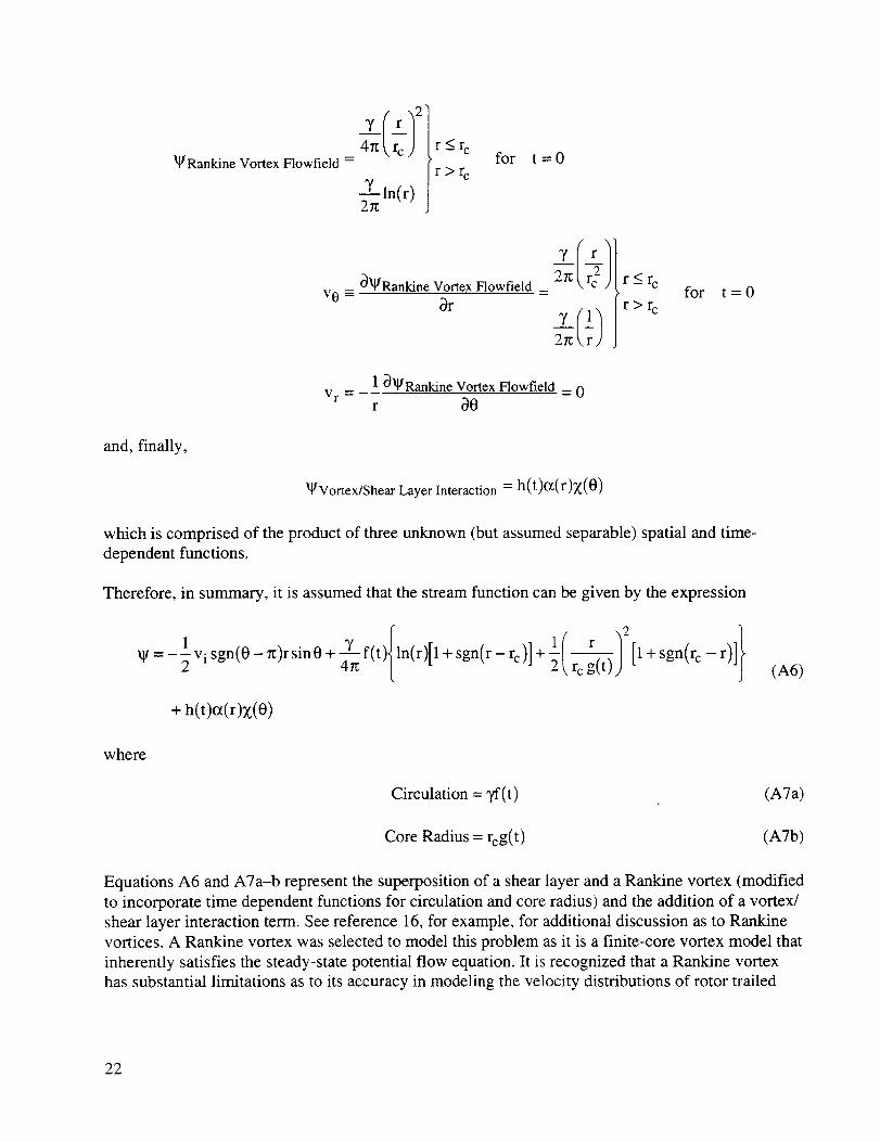
and, finally,
/gVortex/Shear Layer Interaction = h(t)°t(r)X(0)
which is comprised of the product of three unknown (but assumed separable) spatial and time-
dependent functions.
Therefore, in summary, it is assumed that the stream function can be given by the expression
1 vi sgn(0- rt)r sin 0 + 4-_ f(t){ln(r)[1 + sgn(r-rc)] + l(_r 12 [1 + sgn(rc-r)]}_I/=-2 " 2 _,rc g(t))
+ h(t)ot(r);_(0)
(A6)
where
Circulation = 3,f(t)
Core Radius = rcg(t )
(A7a)
(A7b)
Equations A6 and A7a-b represent the superposition of a shear layer and a Rankine vortex (modified
to incorporate time dependent functions for circulation and core radius) and the addition of a vortex/
shear layer interaction term. See reference 16, for example, for additional discussion as to Rankine
vortices. A Rankine vortex was selected to model this problem as it is a finite-core vortex model that
inherently satisfies the steady-state potential flow equation. It is recognized that a Rankine vortex
has substantial limitations as to its accuracy in modeling the velocity distributions of rotor trailed
22

tip vortices.Yet, for thepurposesof thispaper,whichemphasizesdeducingthefirst-order,time-dependentbehaviorof vortexcoresizeandcirculation,thisshouldnotposea concern.
To accommodatetheassumptionof quasi-two-dimensionalflow, thedefinitionof velocity termswith respectto thestreamfunctionwill besubtlymodified:
1_V _r (v r - but v0 = W + W*) (A8a)r 20
where
go, = e(t)tp(r)p(0) (A8b)
p(O) = blnt(-_-)(A8c)
Note that p(0) is a variation on the step ("Heaviside") function---except that the step is progressive
with each crossing of the slipstream/shear layer boundary, p(0) is a generalized function just as the
step, signum, and the Dirac ("delta") functions are (ref. 17). In accordance with the definition/
assumption of quasi-two-dimensional flow, it can be seen that 3vo/30]O=n n o_ 3(p(0))/30 where, as
earlier hypothesized, O(p(0))/_0 _ 15(0 - nrt). The coefficient b in equation A8c is a constant.
Therefore, the velocity functions that satisfy equation A6 must have the form:
Vr = lvi sgn(O - n)cosO- _ h(t)o_(r)_o (z(O))(A9a)
1 sgn(O n)sin 0 + _-_ f(t){(1)[1 + sgn(r - rc)] +v 0 =---_v i
+ h(t)z(o)d (or(r))+ _:(t)p(O) d (q_(r))
r }r2 g(t)2 [1 + sgn(r c -r)](A9b)
where sgn(x) is the signum function, and sgn(x) = -1 for x < 0, sgn(x) = 0 for x = 0, and
sgn(x) = + 1 for x > 0.
The signum and integer functions can be expressed in terms of unit step or Heaviside functions.
Dirac (delta) functions, 5(x), have already been employed in the derivation of the governing equa-
tion, equation A5; Dirac functions will also manifest themselves in the evaluation of equation A5.
The step and Dirac (delta) functions are "generalized" functions (see ref. 17). Formulas for integral
and differential operations applied to generalized functions are well established.
23

The identification of analytical expressions for fit), g(t), h(t), c_(r), Z(0), e(t), and qXr) that satisfy
equation A5 (shown immediately below, once again, for convenience) is the principal undertaking of
this paper.
0 (2_ d0) + 2r_ r O___L_v!l v0 0vr}d 0 --__2vi _v0r 30 Or 0=0,rt
Substitution of equations A9a-b (the assumed functions for the radial and tangential velocities) into
equation A5 yields the following results for the integro-differential terms in equation A5:
O(2rt ) O[2n'l 1 }_-t( ! vrdO =_-l! [-_visgn(O-rt)c°SO-rh(t)°_(r)d-_(Z(e))] dO(A10a)
d (h(t))Z(0)[aor dt
2/{ Ovr_dO= ,{ 1 _0- lvisgn(O-rt)cosO- h(t)o_(r) (z(O)) h(t) (z(O)) dO
Vr Or J 2:
= -1 vih(t)# (0_(r)/2_ (d (Z(0))sgn(0- rl:)cos 0) d 0z or\ r J_ \dO
h2 (t)°_(r) _--r ( _(-_/2.fg ( a-_- (_ (0)) / 2+ dO
(A10b)
24
o
1 [1 +sgn(rc _ r ) vi sgn(O_ n)cosO lh(t)_(r) (x(O))Y f(t) 1 + sgn(r - rc)] + -T-----_ --4rt rc g(t) 2 r 0
_lr 2ff {_lv i sgn(0- n)sin 0 + h(t)Z(0)d(ot(r))+ e(t)p(0)d (qo(r))}{1 vi sgn(0- n)sin 0}d0
1 2_ " 1+-f _--2-Vi sgn(0 - rl:)sin 0 + h(t)Z(0) _rr (o@)) + _;(t)p(0) d (qo(r))}{1 vi d--_(sgn(0 - n))cos 0} d 0
r_L z
_I2=[_1 . 2
+r !J. 2vlsgn(0-n)sin0+h(t)Z(0)d(c_(r))+_(t)p(0)d(q°(r))}{-lh(t)°t(r)d-_(Z(0))}d0
(AlOc)
o-oI :Or O=0,n_1 [1 + sgn(rc - r)]}+ r2 g(t) 2
2 d 2
+ {h(t)Z(0) _5 (o_(r)) + _(t)p(0) d-_ (q0(r))} o=o,n
(Al0d)
Flow visualization of rotor wakes--showing the interaction of the tip vortices with the slipstream--
reveals spiral-like flow patterns (e.g., refs. 9 and 10). This leads to the insight that the vortex/
slipstream interaction term in the stream function could perhaps be approximately represented by
the simple analytic expression for a spiral, _gVortex/Shear Layer Interaction o_ r0.
Proceeding with this insight/hypothesis, it will be shown that equation A5 (for r > rcg(t )) can be
satisfied if the following functional forms for or(r), X(0), and q_(r) are employed:
or(r) = ar (A1 la)
z(O)=ce (A1 lb)
And, further, assume that
go(r) = o_(r) = ar
e(t) = h(t)
(A1 lc)
(A11d)
25

The assumptions explicit in equations A1 lc-d can be rationalized on the basis of functional analysis.
Substituting the assumed functions, equations A1 la-d, into equation A10a-d, for offr), X(0), a(t),
and q0(r), yields:
_ (_2_Vr d 057 0k
= -2gcad(h(t))
2_
{Vr }dO=O0
2= { ? C_Vr; d 0 = Yvi f(t){('_-2 )[ 1+ sgn(r - rc)]"+I _8 J 2---7 r2 g(t)21 [1 + sgn(rc - r)]}o
2n. 1 }1! {___visgn(O_rc)sinO+ah(t)(cO+p(O))}{lvisgn(O_g)sinO d0r
12n r 1
+r ! {-'2 vi sgn(O - _)sin 0 + ah(t)(cO + P(O))}{lvi _0 (sgn(O - _))c°sO} dO
{I 1 I1-'-sgn rc-r'lt=4-_f(t) - [l+sgn(r-rc)]+ 23r 0=0,n rc g(t) 2
Equations A12a--d can be further reduced by noting the following identities (ref. 17):
,q
d--_(sgn(O- rl:))= 2[i(0 - n)
f2f(x_(x- xo)dx = f(Xo)
This is the well-known "sampling property" of the Dirac (delta) function, f(x) is any continuous
function.
IL f(x)u(x - Xo)5(x - xo)dx = I2 f(x)kS(x - xo)dx = kf(xo)
Where u(x - xo), as used in the above equation, is the unit step function, f(x) is any continuous
function, and k is a constant (where 0 < k < 1). Various authors assign several different values to k
but the value used by the majority, and adopted in this paper, is k = 1/2.
(A12a)
(A12b)
(A12c)
(A12d)
(A13a)
(A13b)
(A13c)
26

27_
I sgn(0 - 7z)sin 0d0 = -4
0
2re 2r_
I[sgn(0- r0sin0] 2d0= Isin2 0d0 = rt
0 0
27I
f sgn(0 - re)0 sin 0d0 = -4rt
0
27t
SInt( )sgn 0- )sin0 0---60
Applying equations A 13a-g to equations A 12a-d gives
(2_ de] =_2rccad(h(t) ) L!Vr
Ovr do:Vr Or J 0
I Iv0 3Vr }d0 = + 2_f(t)[l+sgn(r- rc)]+ --0tr 30
+/t(v i ]2 +(_c + 2b) ah(t)vi_-_Yj r
1 [1 + sgn(r c -r)]}re2g(t)2
vOo:o 1Ea+s n,r r) }3r = _-_f(t) - [l+sgn(r-rc)]4 rc2 g(t)2
The constant b, in the function p(0), can be determined by taking into account symmetry
considerations for the vortex interaction, i.e.,
v0]0=n+ = v0]0=0+
which gives (making the appropriate substitutions from eq. A9a into eq. A15)
b = -7_c
(A13d)
(A13e)
(A13f)
(A13g)
(A14a)
(A14b)
(A14c)
(A14d)
(A15)
(A16)
27

Substituting the integro-differential terms of equations A 14a-d back into equation A5 gives
_tt rt v2 rl:acv i h(t)- Yvi f(t) [l+sgn(r c -r)] (AI7)-27tac (h(t))+_r r 2rt r2g(t) 2
Equation A17 can only hold true for r > rcg(t ). Therefore,
-27tacd(h(t))+_v 2 rtacvi h(t)=0 (A18)at 4r r
Equation A 18 then requires that
d(h(t)) = 0
or, more specifically,
h(t)= vi (A19)4ac
Equation A 19 will only be valid until such time as the vortex completely decays out. Once the
vortex decays out then h(t) = 0.
To recap, the stream function that satisfies the r-momentum equation for a Rankine vortex embedded
on a slipstream shear layer has been found to be (for r _>rcg(t))
V=- visgn(0-_)rsin0+ 7f(t)47r ln(r)[l+sgn(r-rc)]+2_,rcg(t))
(A20a)
where k, a constant, is given by
k = v, (A20b)4
and
(A20c)
28
Thepositivesignof theconstant,k, is consistentwith the inward(towardsthevortexcore)radialvelocity thatthe impulsiveforce impartsacrosstheshearlayer.GivenequationsA9a-b, A16, and
A20a-b, the velocities v0 and Vr are therefore
1 sgn(0-n)cos0-kv r -- _- Vi
(A21a)
v 0 =--_vi sgn(0- x)sin0 + f(t) 1+ sgn(r- rc)] +--
+ k(0- xlnt(-_))
]r
[1 + sgn(r c -r)]_rc2g(t) 2 J
(A21b)
Unfortunately, a solution for the stream function for the flow in the vortex core does not suggest
itself at this time. This limitation in the analytical treatment of the vortex/slipstream problem does
not adversely impact the evaluation of the vortex core size and circulation time dependence, as can
be seen in appendix B.
Finally, it should be noted that there is an outer radial limit, ro, for which the derived stream function
applies. Beyond this limit there is no longer any mass transfer (via nonzero vortex tangential
velocities) across the shear layer. This outer limit can be derived by noting that
v0 0=0 = v0 0=_ = 0 at r=r o
which, given equation A21b, yields
T f(t)
2rt roxk =0
Therefore
_' f(t) (A22)ro= 2--
In conclusion, equations A20-A21, inclusive, are valid for the region defined by the radial limits
V f(t)rcg(t) < r < 2---_
29
APPENDIX B - VORTEX CORE SIZE AND CIRCULATION TIME DEPENDENCE
Next, this paper will concentrate on deriving expressions for f(t) and g(t) for the stream function for
r > rc. It is possible to deduce the functional dependence of the vortex core size with time by noting
the following relation.
where
r:rc:(1)
or, making the appropriate substitutions,
- T f(t) r= _ - g2kr
Refer to appendix A for the definitions of _ and _,. The expression for _ requires that
equation B 1a reduce to
_tf(t) [4f(t) 2g2rck] O ,.,=L g(t) "_ J_ -gtt)
Or, alternatively, using the chain rule for derivatives,
df -4 + - 0
The above is a homogeneous, linear ordinary differential equation which has the solution
f(t) : (23_ck)g(t) + (1 23-_ck )g(t '4
The initial value condition (g(0) = frO) = 1) has been accounted for in equation B3.
(B 1a)
(Blb)
(B2)
(B3)
30

To arriveat final closurefor thefunctionsf(t) andg(t), it is necessaryto evaluatethevorticityconservationequation(ref. 18).
_t (IcodV)= -f (r.o•n)udS+ f(nx F)dS (B4a)
where
co= -V2_t (B4b)
and
V2 32 _-10___. 1 32--9 r3r+r 302
Note that V2(_ + _,) and not V2_ is used to defined the vorticity, but 3_/30 is used to define
the vorticity convection velocity into the vortex control volume instead of 3(_ + _.)/30. Refer to
appendix A, equations A20a-c, for the derivation of and expressions for _ and _.. The vorticity
conservation equation, for a control volume about the vortex core, is reducible to (noting that there
are no normal surface forces at the vortex core boundary):
al_-L! _cg(t)v2(_ + Y*)rd
+ r2 dg(t)}g2 (Ig + _,)d0 (B5)
r--re
The vorticity convection into the vortex core, due to the shear-layer-induced radial flow, has to take
into account the vortex core contraction/expansion rate. The vortex core contraction/expansion rated
expression is rc -_-g(t) and has been included in equation B5.
Given equations A20a--c and A21 a-b, the vorticity can be defined by noting that
V2 (_ + _, )= lk{o-rtInt(-_)}- rt--_k8'(0-_)-r vi {28(0- _:)c°s 0+r 8'(0-rt) sin O}
for r _>rcg(t ) (B6)
In the above nomenclature 8'(x)= d(_5(x))/dx. Making the substitution of equation B6 into B5 and
noting the following three points: (1) the control volume boundary is a function of time; (2) only the
vorticity generated by the vortex/shear layer interaction for r >_rcg(t ) is convected into the control2n
--I_cg(t)V2_r dr d0 = yf(t) for the vorticity contained in the vortex core. Thereforefvolume; and (3)o
31

27[
0+ k+ rc dg(t)}d0
The following integral relations are applicable in evaluating equation B7
(B7)
S_¢ f(x)5'(x - x o)dx = -f'(x o) (B8a)
___ f(x)u(x - x o)5,(x - x o)dx = SL f(x)kS'(x - x o)dx : -kf'(x o) (B8b)
where u(x - Xo), as used in the above equation, is the unit step function; f'(x) is the derivative of a
continuous function, f(x), which in itself is also continuous; and k is a constant (where k is arbitrary
in value).
Therefore, application of equations B8a-b to equation B7 results in a first-order, linear differential
equation with the two unknown functions, f(t) and g(t)
d f(t) + (2vi + 7t2rc dg(t))k + rt2k2 = 0vg (B9)
Integrating equation B9 with respect to time yields
7f(t) + g2krcg(t) = g2krc + "{- (2vik + rc2k2)t (B 10)
An initial value constraint of g(0) = frO) = 1 has been accounted for in equation B 10 by solving for
the integration constant. The above equation is a nonlinear implicit solution for the vortex core size.
The vortex core radius can readily be seen to decrease with time by noting an approximation for g(t)
at very large units of time when fit) and, therefore, the circulation approaches zero.
g(t)= 1+1'
/t2krc
2vik + r_2k 2
/_2 krc ) t(B 11 a)
as
t---+_2krc + 7
2vik + g2k2(B 1 lb)
32
Theinterdependenceof the initial valueof circulationandtheslipstreaminflow velocity for rotorwakescanfoundby simplemomentum/vortextheoryfor rotors.Thetrailedcirculationfor atipvortexfilamentshedin rotoraxial flow canbe foundby theexpression(seeref. 8):
4rcRv7 - (U + v) (B12)
NVT
where N is the number of blades and VT is the rotor tip speed. The mean inflow at the rotor disk, v,
is
v = ---+ + (B13)2
As this analysis is applicable for the mid- to far-wake for rotors (i.e., the flow is steady,
nonaccelerating), then based on simple momentum theory for rotors
v i = 2v (B 14)
To conclude this discussion an expression for the wake age required to completely collapse the
vortex will be derived. Referring to equation B 1 lb
Algw = f2t = f2 rt2krc + 72vik + rc2k 2 (B 15)
Making appropriate substitutions from equations B 12, B 13, and B 14 into equation B 15 yields
A_w = (re2 + 81(f_rc _ + I2rt2 + 16;((B16)
33

APPENDIX C - VORTEX FILAMENT AXIAL FLOW
Axial Flow Along Slipstream Boundary for t << A_w/_2
The vortex/shear layer interaction problem has been assumed to be quasi-two-dimensional. This has
been defined to be
av-----_z= 0 for 0 _ nx where n = 0,1,2 ....az
but
av z av z at 1 av z- - _:0 for 0=nxaz at az v z at
The continuity equation along the shear layer/slipstream boundary can be rewritten as
1 av z _fay r v r _1Ov0 _= +--+ (C1)v z at { Dr r r 20 J
which gives
Vz e-.t'_aVr +Vr +lavo _dt= [ ar r r aO J (C2)
Finally, expressions for Vr and v0 have been derived in appendix A and are given by equations 9 and
10 in the main body of the paper. Making the appropriate substitutions
v z = e r_kS(O-nx)t/r (C3)
Equation C3 predicts that Vz is a constant for r < ro (refer to appendix A, eq. A22, for the
definition/derivation of ro) for all 0---except along the slipstream boundary, i.e., 0 = nn. For
0 = nn, equation C3 describes a line-sink; some of the tangential mass flow crossing the slipstream
boundary is redirected and convected axially along the shear layer. Continuity has, therefore,
been shown to be preserved even at the discontinuous slipstream boundary (if one overcomes the
conceptual hurdle of an infinite axial velocity, acting along an infinitesimal shear layer thickness,
that increases with time). Equation C3 should be seen as a limiting case for more realistic shear layer
models (shear layer gradients that are steep but not discontinuous). Therefore, axial velocities for
actual rotor trailed tip vortices are large but finite, are concentrated at the slipstream boundary as
"swirl," and increase with time. Equation C3 provides an insight into observations of a large particle
void seen in smoke flow visualization studies of rotor vortex filaments in that a finite axial flow is
predicted for the remainder of the region r < ro.
34

Axial Flow Along Slipstream Boundary for t --->oo
The angular momentum in rotor vortex filaments, as they decay, is transformed to axial
(z coordinate) momentum. Turning to the Navier-Stokes momentum equation for Vz
Dvz OVz+ 1 Dvz+ v Dvz 1 aP t- vV2Vz-- + v r v0 -Dt Dr r D0 z Dz p Dz
Now, as previously noted, and continuing to assume inviscid flow
Therefore
D__p_P=0 and Dvz_ 1 Dv z
Dz Dz v z Dt
Dvz 1 Dvz Dv z
-_-+ + _=0rVO-_ - Vr Dr
An asymptotic solution will now be derived for time approaching infinity, i.e. t ---) _. This
asymptotic solution is applicable only for r > rc.
Note that as the vortex core collapses, then
DVz _ 0Dt
and
Therefore, it can be readily seen that
f(t)---_ 0
k=0 as t --->_
v z ---> Ae -b_t as t _ oo
where A and b are arbitrary constants. Also, as t _ oo, then
lvisgn( 0- x)rsin0 (as the vortex core collapses)-..)
Therefore, the axial velocity distribution must approach
b
v z _ Ae_Visgn(0-r0 rsin0
(C4)
(C5)
(C6)
35
for
t ---) oo
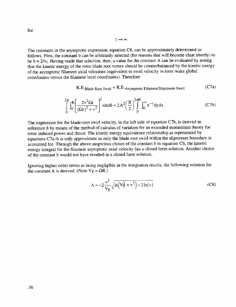
The constants in the asymptotic expression, equation C6, can be approximately determined as
follows. First, the constant b can be arbitrarily selected (for reasons that will become clear shortly) to
be b = 2/vi. Having made that selection, then, a value for the constant A can be evaluated by noting
that the kinetic energy of the rotor blade root vortex should be counterbalanced by the kinetic energy
of the asymptotic filament axial velocities (equivalent to swirl velocity in rotor wake globalcoordinates versus the filament local coordinates). Therefore
K-E-Blade Root Swirl = K'E'Asymptotic Filament/Slipstream Swirl (CTa)
!fRI 2v2f2r ] 2 2A2(R)2!RIoe-Ydydx7z, rdrd0 --
(C7b)
The expression for the blade-root swirl velocity, in the left side of equation C7b, is derived in
reference 8 by means of the method of calculus of variation for an extended momentum theory for
rotor induced power and thrust. The kinetic energy equivalence relationship as represented by
equations C7a-b is only approximate as only the blade root swirl within the slipstream boundary is
accounted for. Through the above auspicious choice of the constant b in equation C6, the kinetic
energy integral for the filament asymptotic axial velocity has a closed form solution. Another choiceof the constant b would not have resulted in a closed form solution.
Ignoring higher order terms as being negligible in the integration results, the following solution for
the constant A is derived. (Note VT = _R.)
A =-2 v2 _/ln(V 2 + v2)- 21n(v)VTv
(C8)
36

REFERENCES
.
.
.
.
.
.
7.
°
9.
10.
13.
Gray, R. B.: Vortex Modeling for Rotor Aerodynamics--The 1991 Alexander A. NikolskyLecture. 47th Annual Forum of the American Helicopter Society, Phoenix, Ariz., May 1991.
Swanson, A.; and Light, J.: Shadowgraph Flow Visualization of Isolated Tiltrotor and
Rotor/Wing Wakes. 48th Annual Forum of the American Helicopter Society, Washington,
D.C., June 1992.
Leishman, J. G.; Baker, A.; and Coyne, A.: Measurements of Rotor Tip Vortices Using Three-
Component Laser Doppler Velocimetry. American Helicopter Society Aeromechanics
Conference, Fairfield County, Conn., October 1995.
Han, Y. O.; Leishman, J. G.; and Coyne, A. J.: On the Turbulent Structure of a Tip Vortex
Generated by a Rotor. 52nd Annual Forum of the American Helicopter Society,
Washington, D.C., June 4-6, 1996.
Baker, A. M.: Three-Component Laser Doppler Velocimeter Measurements of a Tip Vortex
Generated by a One-Bladed Rotor. Masters of Science Thesis, University of Maryland,1995.
Lamb, H.: Hydrodynamics, Sixth Edition. Dover Publications, New York, 1945.
Friedrichs, K. O.: Special Topics in Fluid Dynamics. Gordon & Breach, Science Publishers,
New York, 1966.
Johnson, W.: Helicopter Theory. Princeton University Press, 1980.
Landgrebe, A. J.: The Wake Geometry of a Hovering Helicopter Rotor and Its Influence onRotor Performance. 28th Annual Forum of the American Helicopter Society, Washington,
D.C., May 1972.
Favier, D.; Ettaouil, A.; and Maresca C.: Numerical and Experimental Investigation of Isolated
Propeller Wakes in Axial Flight. AIAA Journal of Aircraft, vol. 26, no. 9, September 1989.
Saffman, P. G.: Vortex Dynamics. Cambridge University Press, 1992.
Adams, G. N.; and Gilmore, D. C.: Some Observations of Vortex Core Structure. Canadian
Aeronautics and Space Journal, June 1972.
Thompson, T. L.; Komerath, N. M.; and Gray, R. B.: Visualization and Measurement of the
Tip Vortex Core of a Rotor Blade in Hover. AIAA Journal of Aircraft, vol. 25, no. 12,
December 1988.
37

14. Hylin, E. C.; andMcDonough,J.M.: Additive TurbulentDecompositionApplied to anIsolatedVortex in aConstantShearFlow. FourthInternationalSymposiumonComputationalFluidDynamics,Universityof California,Davis,September9-12, 1991.
15. Wylie, C. R.: Advanced Engineering Mathematics, Fourth Edition. McGraw-Hill, 1975.
16. Durand, W. F.: Aerodynamic Theory. 1934.
17. Hoskins, R. F.: Generalised Functions. Ellis Horwood, Ltd., Chichester, United Kingdom of
Great Britain, 1979.
18. White, F. M.: Viscous Fluid Dynamics. McGraw-Hill, 1974.
38
Form Approved
REPORT DOCUMENTATION PAGE OMBNO.0704-0188
Public reporting burden for this collection of information is estimated to average 1 hour per response, including the time for reviewing instructions, searching existing data sources,gathering and maintaining the data needed, and completing and reviewing the collection of information. Send comments regarding this burden estimate or any other aspect ol thiscollection of information, including suggestions for reducing this burden, to Washington Headquarters Services, Directorate for information Operations and Reports, 1215 JeffersonDavis Highway. Suite 1204, Arlington. VA 22202-4302, and to the Office of Management and Budget, Paperwork Reduction Project (0704-0188), Washington. DC 20503.
1. AGENCY USE ONLY (Leave blank) 2. REPORT DATE 3. REPORT TYPE AND DATES COVERED
January 1997 Technical Memorandum4. TITLE AND SUBTITLE 5. FUNDING NUMBERS
Rotor Vortex Filaments: Living on the Slipstream's Edge
6. AUTHOR(S)
Larry A. Young
7. PERFORMINGORGANIZATIONNAME(S)ANDADDRESS(ES)
Ames Research Center
Moffett Field, CA 94035-1000
9. SPONSORING/MONITORINGAGENCYNAME(S)ANDADDRESS(ES)
National Aeronautics and Space Administration
Washington, DC 20546-0001
505-59-36
8. PERFORMING ORGANIZATIONREPORT NUMBER
A-975569
10. SPONSORING/MONITORINGAGENCY REPORT NUMBER
NASA TM- 110431
11. SUPPLEMENTARY NOTES
Point of Contact: Larry A. Young, Ames Research Center, MS T12-B, Moffett Field, CA 94035-1000
(415) 604-4022
12a. DISTRIBUTION/AVAILABILITY STATEMENT '12b. DISTRIBUTION CODE
Unclassified -- Unlimited
Subject Category 02
13. ABSTRACT (Maximum 200 words)
The purpose of this paper is to gain a better understanding of rotor wake evolution in hover and
axial flow by deriving an analytical solution for the time dependent behavior of vortex filament circulation
and core size. This solution is applicable only for vortex filaments in the rotor far-wake.
A primarily inviscid vortex/shear layer interaction (where the slipstream boundary is modeled as
a shear layer) has been identified in this analytical treatment. This vortex/shear layer interaction results in
decreasing vortex filament circulation and core size with time. The inviscid vortex/shear layer interaction isshown, in a first-order treatment, to be of greater magnitude than viscous diffusion effects. The rate of
contraction, and ultimate collapse, of the vortex filament core is found to be directly proportional to the rotor
inflow velocity.This new insight into vortex filament decay promises to help reconcile several disparate observations
made in the literature and will, hopefully, promote new advances in theoretical modeling of rotor wakes.
14. SUBJECT TERMS
Rotors, Vortices, Shear layer
17. SECURITY CLASSIFICATION 18. SECURITY CLASSIFICATIONOF REPORT OF THIS PAGE
Unclassified Unclassified
NSN 7540-01-280-5500
19. SECURITY CLASSIFICATION
OF ABSTRACT
15. NUMBER OF PAGES
4316. PRICE CODE
A03
20. LIMITATION OF ABSTRACT
Standard Form 298 (Rev. 2-89)Prescribed by ANSI Std. Z39-18
