rotary inertia and higher modes effect on the dynamic
TRANSCRIPT

Teknik Dergi, 2019 9289-9308, Paper 544
Rotary Inertia and Higher Modes Effect on the Dynamic Response of Timoshenko Beams on Two-Parameter Elastic Foundation* Çağlayan HIZAL1 Hikmet Hüseyin ÇATAL2 ABSTRACT
This study investigates the effects of rotary inertia and higher modes on the dynamic response of the axially loaded Timoshenko beams on two-parameter foundation with generalized elastic end conditions. A simplified modal analysis procedure is presented by using the conventional separation of variables method. The effect of rotary inertia on the solution of free vibration differential equation is discussed. A numerical example is presented to investigate the coupled effect of rotary inertia and higher modes on the bending moment and shear force responses.
Keywords: Rotary inertia, higher modes effect, separation of variables method, two parameter-foundation.
1. INTRODUCTION
The dynamic behavior of axially loaded beams on elastic foundation has gained the attention of many researchers. The Winkler type foundation, which is the best known of the elastic soil models, has been widely used for the estimation of soil-structure interaction. A great number of studies exist in the literature regarding the dynamic response of Euler or Timoshenko beams on Winkler type foundations [1-2]. Çatal [3, 4] obtained the fourth order differential equations by using the separation of variables method for the beams partially resting on Winkler foundation with the axial force and rotary inertia effects. A particular case, in which the free vibration equation of motion has five different solutions depending on the subgrade modulus was highlighted. Yeşilce and Çatal [5] investigated the free vibration of the Timoshenko beams on Winkler foundation with different subgrade reactions. Differential transform method (DTM) was adopted by Çatal [6] to the free vibration equations of the
Note:
- This paper has been received on March 23, 2018 and accepted for publication by the Editorial Board on November 12, 2018.
- Discussions on this paper will be accepted by September 30, 2019. https://dx.doi.org/10.18400/tekderg.408772 1 Izmir Institute of Technology, Dep. of Civil Engineering, İzmir, Turkey - [email protected] -
https://orcid.org/0000-0002-9783-6511 2 Dokuz Eylul University, Department of Civil Engineering, İzmir, Turkey - [email protected]

Rotary Inertia and Higher Modes Effect on the Dynamic Response of Timoshenko …
9290
Timoshenko beams resting on Winkler type foundation and verified by the analytical results. Yeşilce et al. used the DTM for the free vibration analysis of axially loaded Reddy-Bickford beams [7-8]. Sapountzakis and Kampitsis [9] investigated the nonlinear behavior of the beams partially supported by tensionless Winkler foundation. Çatal [10] obtained the displacement response of forced Euler-Bernoulli beams on Winkler foundation by using the DTM. Öztürk and Coskun [11] obtained the analytical solution for the free vibration of beams on Winkler foundation with different support conditions.
In the Winkler model, the elastic soil is represented by independent linear springs within an infinitesimal part of the beam. More realistic approaches such as the two-parameter elastic foundation approach was proposed by Pasternak [12], and Vlasov and Leont’ev [13], respectively. These type of foundation models suppose that an interaction is constituted between Winkler springs by the transverse displacement [12-13]. This interaction is defined by a second parameter which represents the shear coefficient of an incompressible shear layer on the soil surface. In Pasternak model, the influence of the soil to both sides of the foundation beam is ignored as opposed to the Vlasov Model. Despite this difference, the second parameter can be taken equal for both models by considering the soil layer as a semi-infinite elastic medium [14]. Various researchers studied the behavior of the beams on two parameter foundations. Yokoyama [15] obtained the stiffness and mass matrices for the free vibration of Timoshenko beam-columns on two-parameter foundation with the effect of rotary inertia. Arboleda-Monsalve et al. [16] analyzed axially Timoshenko beam-columns with generalized end conditions on two parameter elastic foundation with rotary inertia by using the dynamic stiffness approach. Balkaya et al. [17] analyzed the dynamic response of the beams on Winkler and Pasternak foundation by using DTM. Celep et al. [18] calculated the response of a completely free beam on a tensionless Pasternak foundation subjected to dynamic loading. Malekzadeh and Karami [19] analyzed the free vibration of thick beams on two-parameter elastic foundations by using the differential quadrature and finite element method. Morfidis [20] obtained the exact finite element formulation for the dynamic analysis of beams on two and three-parameter foundations. Calio and Greco [21] investigated the exact free vibrations of Timoshenko beams and compared their results by Yokoyama [15]. Hassan and Nassar [22] obtained the dynamic displacement response of the axially loaded Timoshenko beams on two-parameter foundation.
Most previous studies investigate the dynamic response considering a few modes (commonly 3 or 5 modes). The effect of higher modes on the vibration is generally omitted. Although, the contribution of first 3-5 modes generally yield the exact results for displacement response, the bending moment and shear force response might be affected ultimately by the higher modes. Hızal and Çatal [23] mentioned that case and gave a small illustrative example. However, their study focused on the comparison of dynamic response of the Euler and Timoshenko beams on modified Vlasov foundation. In addition to the mentioned problems, the solution of the differential equation of free vibration might be affected by the rotary inertia in higher modes. For this reason, the required number of modes should be investigated considering the coupled effect of rotary inertia and higher modes.
In this study, a general solution for the dynamic behavior of axially loaded Timoshenko beams on two-parameter foundation with generalized end condition is presented. To the knowledge of the authors, the effect of higher modes on the dynamic response incorporated with the rotary inertia effect is not investigated in the literature. Different from the previous

Çağlayan HIZAL, Hikmet Hüseyin ÇATAL
9291
researches, a comprehensive study is presented to show the coupled effect of higher modes and rotary inertia on the dynamic response. The effect of the rotary inertia on the solution procedure is discussed. Modal variations in the bending moment and shear force responses of Euler and Timoshenko beams with respect to the foundation type, axial force and rotary inertia are presented.
2. GOVERNING EQUATIONS
In Fig. (1), the free body diagram of an infinitesimal part of an axially loaded Timoshenko beam element is presented. Here, the transverse force and moment equilibrium of the given infinitesimal part can be written as below according to the non-dimensional coordinate, z=x/L.
Figure 1 - (a) Timoshenko beam resting on two-parameter elastic foundation (b) Free
body-diagram of infinitesimal element obtained from the beam
yL
N Nx
C
Cy
C
Cy
(a)
C y(x)dxS
dx(b)
y(x,t)x dx
(x,t)mr² ²t²
dx
[CS y(x,t)+CG dxy(x,t)]x
y(x,t)m ²t²
dx
T(x,t)+ T(x,t)x dx
M(x,t)+ M(x,t)x dx
T(x,t)
M(x,t)N
N
y(x,t)/x
f (x,t)
Shear layer (Second parameter), CG
Winkler springs (First parameter), CS
Rotary Inertia and Higher Modes Effect on the Dynamic Response of Timoshenko …
9292
tzfx
tzyL
CtzyCt
tzymz
tzTL GS ,),(1),(),(),(1
2
2
22
2
(1)
22
21 ( , ) 1 ( , ) ( , ) ( , )M z t y z t θ z tN mr T z tL z L z t
(2)
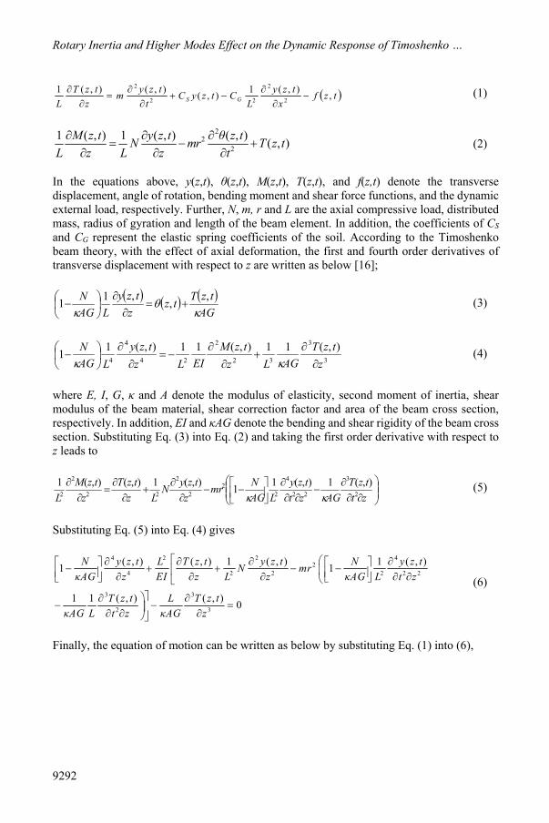
In the equations above, y(z,t), θ(z,t), M(z,t), T(z,t), and f(z,t) denote the transverse displacement, angle of rotation, bending moment and shear force functions, and the dynamic external load, respectively. Further, N, m, r and L are the axial compressive load, distributed mass, radius of gyration and length of the beam element. In addition, the coefficients of CS and CG represent the elastic spring coefficients of the soil. According to the Timoshenko beam theory, with the effect of axial deformation, the first and fourth order derivatives of transverse displacement with respect to z are written as below [16];
AG
tzTtzz
tzyLAG
N
,,,11
(3)
3
3
32
2
24
4
4
),(11),(11),(11z
tzTAGLz
tzMEILz
tzyLAG
N
(4)
where E, I, G, κ and A denote the modulus of elasticity, second moment of inertia, shear modulus of the beam material, shear correction factor and area of the beam cross section, respectively. In addition, EI and κAG denote the bending and shear rigidity of the beam cross section. Substituting Eq. (3) into Eq. (2) and taking the first order derivative with respect to z leads to
zttzT
AGzttzy
LAGNmr
ztzyN
LztzT
ztzM
L 2
3
22
4
22
2
2
22
2
2),(1),(11),(1),(),(1
(5)
Substituting Eq. (5) into Eq. (4) gives
4 2 2 42
4 2 2 2 2 2
3 3
2 3
( , ) ( , ) 1 ( , ) 1 ( , )1 1
1 1 ( , ) ( , ) 0
N y z t L T z t y z t N y z tN mrκAG z EI z L z κAG L t z
T z t L T z tκAG L t z κAG z
(6)
Finally, the equation of motion can be written as below by substituting Eq. (1) into (6),

Çağlayan HIZAL, Hikmet Hüseyin ÇATAL
9293
4 2 2 42 2 2
4 2 2 2 2
2 4 2 4 2 4 42 2
2 2 2 2 4 4
( , ) 1 ( , ) ( , ) ( , )1 ( , ) 1
( , ) 1 ( , ) ( , ) ( , ) ( , )
S G
S G
N y z t y z t y z t N y z tmL C L y z t C mrκAG z EI t z κAG t z
y z t y z t y z t y z t mr L y z tN mL C L C mz κAG t z z z EIκAG t
2 4 2 2 2 2
2 2 2 2 2 2( , ) ( , ) ( , ) ( , ) ( , )G
SCy z t y z t L f z t L f z t Lmr f z tC
t L z t κAG z EI κAGEI t
(7)
3. MODAL ANALYSIS PROCEDURE
3.1. Free Vibration Analysis
In Eqs. (1-7), deformations and internal forces of the beam element are defined as depending on the location and time variables. These parameters can be divided into two parts with the implementation of the method of the separation of variables as follows;
1
)()(),(i
ii tqzYtzy (8)
1
)()(),(i
ii tqztz (9)
1
)()(),(i
ii tqzMtzM (10)
1
)()(),(i
ii tqzTtzT (11)
where i denotes the mode number and 𝑌 (𝑧), 𝛩 (𝑧), 𝑀 (𝑧), 𝑇 (𝑧) and q (t) are the displacement, angle of rotation, bending moment, shear force shape functions and the normal coordinate function, respectively. In the free vibration case (for f(z,t)=0), the normal coordinate function can be taken as qi(t)=sin(ωit+𝜑). Thus, the Eq. (7) can be written in the following form.
2 2 2 222
224 4 2 0
i G i GIV IIi si i
G
i si s i i
G
mω r N C mω r C Nmω CκAGY z L Y zκAG N C κAG EI EIκAG
mω CκAG mrL mω C ω Y zκAG N C EIκAG EI
(12)

Rotary Inertia and Higher Modes Effect on the Dynamic Response of Timoshenko …
9294
where ωi and φ denote the natural angular frequency of ith mode and the phase angle. Then, the shape functions of the bending moment, shear force and angle of rotation are obtained as [23].
2
2
2 2
2 2
( )( ) ( ) 1
( ) ( )( )
1
( ) ( )( ) 1
ııs i G i
i i
ı ıi i i
ii
ıi i
i
C mω C N Y zM z EI Y zκAG κAG L
M z mω r N Y zT ξ
mω r LκAG
Y z T zNΘ zκAG L κAG
(13)
In Eq. (13), it is seen that the displacement shape function is required to obtain 𝑀 (𝑧), 𝑇 (𝑧) and 𝛩 (𝑧). For this reason, the displacement shape function should be obtained at first. For this purpose, Eq. (12) can be written as;
0IV IIi i i i iY z a Y z bY z (14)
where
AGEI
NCrmEI
CNrmAG
CmCAG
AGLa GiGisi
Gi
222222
(15)
EINCAGCmAGL
AGmr
bG
siii
2422
1 (16)
The roots of the differential equation given in Eq. (14) are obtained as;
242
21
iii baa
242
22
iii baa (17)
Although the differential equation given in Eq. (14) involves six different solutions depending on the sign of λ1
2 and λ22, only three of them, Case-I: λ1
2 < 0 and λ22 > 0, Case-II:
λ12 < 0 and λ2
2 = 0, and Case-III: λ12 < 0 and λ2
2 < 0 are physically possible. If the beam rests on a uniform elastic soil and the rotary inertia is considered, the lower modes satisfy Case-I for ωi
2 < κAG/(mr2). However, this case is violated for higher modes and case-II and III is satisfied for ωi
2 = κAG/(mr2) and ωi2 > κAG/(mr2), respectively. In the case that the rotary
inertia is neglected, the Case-I will satisfy all modes since the κAG/(mr2) will be infinite. Thus, the shape functions are obtained for Case-I, Case-II and Case-III as follows.
For Case-I: λ12 < 0 and λ2
2 > 0;

Çağlayan HIZAL, Hikmet Hüseyin ÇATAL
9295
zCzCzCzCzYi 24231211 sinhcoshsincos)( (18)
zKCzKCzKCzKCzi 274273162151 coshsinhcossin)( (19)
zKCzKCzKCzKCzM i 224223112111 sinhcoshsincos)( (20)
zKCzKCzKCzKCzT i 244243132131 coshsinhcossin)( (21)
where
242
1iii baa
242
2iii baa
(22)
and
2 2s 1
1 2
2 2s 2
2 2
2 2 2 21 1 2 2 31
3 4 52 2 2 2
316
EI C -m1 ,
AG
EI C -m1
AG
m m, ,
L(-m /kAG 1) L(-m /kAG 1) L AG
1L AG
i G
i G
i i
i i
ω C N EIλKκ κAG L
ω C N EIλKκ κAG L
λ K ω r N λ K ω r N KλK K Kω r ω r κ
Kλ NKκ
2 47, 1
AG L AG AG
λ N KKκ κ κ
(23)
For Case-II: λ12 < 0 and λ2
2 = 0;
1 1 2 1 3 4cos cosiY z C λ z C λ z C z C (24)
1 5 1 2 6 1 3 7sin siniΘ z C K λ z C K λ z C K (25)
1 1 1 2 1 1 3 2 4 2cos cosiM z C K λ z C K λ z C K z C K (26)
1 3 1 2 3 1 3 4sin siniT z C K λ z C K λ z C K (27)
and

Rotary Inertia and Higher Modes Effect on the Dynamic Response of Timoshenko …
9296
2 22s s1
1 22
2 2 2 21 1 2 2 31
3 4 52 2 2 2
316 7
EI C -m EI C -m1 ,
AG AG
m m, ,
L AGL(-m /kAG 1) L(-m /kAG 1)
11 , 1L AG AG L AG
i iG
i i
i i
ω ωC N EIλK Kκ κAG κL
λ K ω r N λ K ω r N KλK K Kκω r ω r
Kλ N NK Kκ κ κ
4
AGKκ
(28)
For Case-III: λ12 < 0 and λ2
2 < 0;
1 1 2 1 3 2 4 2( ) cos sin cos siniY z C λ z C λ z C λ z C λ z (29)
1 5 1 2 6 1 3 7 2 4 8 2( ) sin cos sin cosiΘ z C K λ z C K λ z C K λ z C K λ z (30)
1 1 1 2 1 1 3 2 2 4 2 2( ) cos sin cos siniM z C K λ z C K λ z C K λ z C K λ z (31)
1 3 1 2 3 1 3 4 2 4 4 2( ) sin cos sin cosiT z C K λ z C K λ z C K λ z C K λ z (32)
where
242
1iii baa
2
42
2iii baa
(33)
and
2 22 2s s1 2
1 22 2
2 2 2 21 1 2 2 31
3 4 52 2 2 2
16
EI C -m EI C -m1 , 1
AG AG
m m, ,
L AGL(-m /kAG 1) L(-m /kAG 1)
1L AG
i iG G
i i
i i
ω ωC N C NEIλ EIλK Kκ κAG κ κAGL L
λ K ω r N λ K ω r N KλK K Kκω r ω r
Kλ NKκ
3 2 4 2 47 8, 1 , 1
AG L AG AG L AG AGλ K λ KN NK K
κ κ κ κ κ
(34)
An iterative computer program that determines the natural angular frequencies and mode shapes for the beam on an elastic foundation has been prepared by the authors. This program obtains the natural angular frequencies, and mode shapes for generalized end conditions. Here, the end conditions are defined by elastic supports with the coefficients of Cy0, Cθ0, Cy1, Cθ1 as below;

Çağlayan HIZAL, Hikmet Hüseyin ÇATAL
9297
01)1(
01)1(00)0(
00)0(
1
1
0
0
zMzCzTzyC
zMzCzTzyC
y
y
(35)
Then, the coefficient matrix is obtained as follows;
for Case-I;
0 3 0 4
1 6 0
- -
y yC K C KK K C
2 7 0
1 1 3 1 1 1 3 1 1 2 2 1 1 2 4 2
1 5 1 1 1
cos sin sin cosh cosh sinh sinh cosh
sin cos
y y y y
K K C
C K C K C K C K
C K K C
1 6 1 1 1 1 7 2 1 2 1 6 2 2 2cos sin sinh cosh cosh sinh
K K C K K C K K
(36)
for Case-II;
0 3 0
1 6 0
- 0
y yC K CK K C
2
1 1 3 1 1 1 3 1 1 2 3 1 2
1 5 1 1 1 1 6 1 1 1 1 7 2 1
0
cos sin sin cos cos sin
sin cos cos sin sin
y y y y
K
C K C K C K C
C K K C K K C K K
0
(37)
for Case-III;
0 3 0 4
1 6 0
- -
y yC K C KK K C
2 7 0
1 1 3 1 1 1 3 1 1 2 3 1 1 2 4 2
1 5 1 1 1 1
cos sin sin cos cos sin sin cos
sin cos
y y y y
K K C
C K C K C K C K
C K K C
6 1 1 1 1 7 2 1 21 1 8 2 2 2cos sin sin cos cos sin
K K C K K C K K
(38)
The coefficients of C2, C3 and C4 can be obtained as below by setting, C1 = 1.
122 23 342 21
3 32 33 34 31
4 42 43 44 41
---
CCC
(39)
Once, C2, C3 and C4 are obtained, Yi(z) can be normalized so that its maximum value will be equal to 1.
3.2. Forced Vibration Analysis
Once the natural angular frequencies and free vibration mode shapes are obtained, the rest of the problem can be easily solved numerically. The forced vibration case can be handled as a set of linear algebraic equations by deriving the uncoupled equations of motion. Finally, a

Rotary Inertia and Higher Modes Effect on the Dynamic Response of Timoshenko …
9298
linear dynamic analysis can be performed. For this propose, the separation of variables method can be applied to the Eqs. (1) and (2).
21
1 1( ) ( ) ( ) ( ) ( ) ( ) ( , )ıı ıi i S i G i i i
imY ξ q t C Y z C Y ξ T z q t f z t
L L
(40)
2
1
1 1( ) ( ) ( ) ( ) ( ) ( ) 0ı ıi i i i i i
imr z q t M z NY z T z q t
L LΘ
(41)
Multiplying the both sides of Eq. (40) by Yj(z), and Eq. (41) by Θj(z), and integrating them along the beam length, the following equation is obtained according to the rule of the orthogonality of modes.
1 1 12
0 0 0
( )( ) ( ) ( ) ( ) ( ) ( ) ( ) ( )
IIG j
j j j S j j j j j
C Y zmLY z q t dz Y z LC Y z T z q t dz mLY z q t dz
L
(42)
1 1
2
0 0
( ) ( ) ( ) ( ) ( ) ( ) ( ) 0I Ij j j j j jmLΘ z q t dz Θ z M z NY z LT z q t dz (43)
Assembling Eqs. (42) and (43) yields,
( ) ( ) ( )j j j j jM q t K q t F t (44)
where Mj, Kj, and Fj(t) denote the generalized mass, stiffness, and load at the jth mode, respectively.
12 2 2
0
1
0
1
0
( ) ( )
( )( ) ( ) ( ) ( ) ( ) ( ) ( )
( ) ,
j j j
IIG j I I
j j S j j j j j
j j
M mL Y z r Θ z dz
C Y zK Y z LC Y z T z Θ z M z NY z LT z dz
L
F t L Y z f z t dz
(45)
Substituting Kj=Mjωj2 into Eq. (44) leads to the following equation
2 ( )( ) ( ) j
j j jj
F tq t ω q t dz
M (46)
Thus, the normal coordinate function can be obtained by the solution of Eq. (46).

Çağlayan HIZAL, Hikmet Hüseyin ÇATAL
9299
4. CALCULATION OF SOIL PARAMETERS
The first parameter of the elastic soil which represents the modulus of transverse deformation can be evaluated by using the formulas given for the Winkler foundation model. On the other hand, the calculation of the second parameter is directly related to the type of the two-parameter elastic soil model. Vlasov and Leont’ev [13] proposed a formula for the calculation of the first and second parameters for rectangular beams on an elastic soil layer. These formulas were simplified by Zhaohua and Cook [24] for a semi-infinite elastic medium as given below.
lbEC o
S
)1(2 20
lbEC o
G )1(4 0
(47)
where, 𝑏 denotes the width of the beam. The parameter of �̅� is defined by Vlasov and Leont’ev as a coefficient that characterizes the decrease of deflections with depth and commonly taken as �̅� = 1. Parameters of l, Eo, υo are given in the following equation.
3
02
20
)1()1(2
bEEI
l
(48)
s
so
s
so
EE
11 2
(49)
where Es, υs and υ denotes the modulus of elasticity and Poisson’s ratio of the soil and the beam, respectively.
5. NUMERICAL RESULTS AND DISCUSSIONS
5.1. Verification Example
A numerical example which was previously studied by Yokoyama [15], and Calio and Greco [21] is presented to verify the presented solution procedure. The free vibration of the axially loaded hinged-hinged and fixed-hinged beam on Winkler and Pasternak foundation is investigated and analysis results are compared with those of the Yokoyama [15], and Calio and Greco [21]. The beam and soil properties are calculated according to the non-dimensional parameters below [25].
EINLn 2
2
(50)
EILC
c Ss
2
(51)

Rotary Inertia and Higher Modes Effect on the Dynamic Response of Timoshenko …
9300
EILCc G
g 2
2
(52)
Where 𝑛, 𝑐̅ and 𝑐̅ denotes the dimensionless axial force, the first and second parameters of the elastic soil. The dimensionless frequency parameters, Ωi = EI /(L4ωi
2m) of the first three modes obtained for the hinged-hinged and fixed-hinged beam are presented in Table-1 and 2, respectively. In Table-1, the frequency parameter obtained by the present study is found to be very close to the results presented by Yokoyama [15]. A small difference is obtained in second and third mode due to the fact that Yokoyama [15] presents a finite element solution by using 16 bar elements. Note that the difference with the Yokoyama solution [15] decreases for Vlasov type foundation as given in Table-2. In addition, a good agreement is obtained with the exact analytical results presented by Calio and Greco [21].
Table 1 - Frequency parameters obtained for 𝑛=0.6, 𝑐̅ =0.6π4 and 𝑐̅ =0 (κ=2/3 and L/r=10.0)
Mode Number
Hinged-Hinged Fixed-Hinged Present Study
Yokoyama [15]
Present Study
Yokoyama [15]
1 8.22 8.22 10.46 10.49 2 20.59 20.67 22.20 22.30 3 35.86 36.25 36.50 36.90
Table 2 - Frequency parameters obtained for 𝑛=0.6, 𝑐̅ =0.6π4 and 𝑐̅ =1 (κ=2/3 and L/r=10.0)
Mode
Number
Hinged-Hinged Fixed-Hinged Present Study
Yokoyama [15]
Calio and Greco [21]
Present Study Yokoyama [15]
1 12.64 12.64 12.64 14.42 14.42 2 28.03 28.10 28.02 29.30 29.34 3 45.92 46.34 45.92 46.70 46.74
The variation of dimensionless eigenvalues µ1 = λ12 EI /(L4ωi
2m) and µ2 = λ22 EI /(L4ωi
2m) for the hinged-hinged and fixed-hinged support conditions are given in Figures 3-4, respectively. When the rotary inertia is neglected, Case-I is satisfied for all modes. For the hinged-hinged beam, when the rotary inertia is considered, Case-I is violated starting from the 4th and 5th modes, for the Winkler and Vlasov foundations, respectively. However, the higher modes satisfy Case-III. For the fixed-hinged beam, Case-I is satisfied up to the 3rd mode.

Çağlayan HIZAL, Hikmet Hüseyin ÇATAL
9301
Figure 2 - Normalized mode shape functions obtained for first three modes
Figure 3 - Normalized eigenvalues for the hinged-hinged beam
Figure 4 - Normalized eigenvalues for the fixed-hinged beam
0 0.2 0.4 0.6 0.8 1−1
−0.8
−0.6
−0.4
−0.2
0
0.2
0.4
0.6
0.8
1
Y(z
)
z
1st Mode (H−H)
2nd Mode (H−H)
3rd Mode (H−H)
1st Mode (F−H)
2nd Mode (F−H)
3rd Mode (F−H)
0 5 10 15 20−25
−20
−15
−10
−5
0
Mode Number
1
Winkler without R.I. Winkler with R.I. Vlasov without R.I. Vlasov with R.I.
0 5 10 15 20−4
−3.5
−3
−2.5
−2
−1.5
−1
−0.5
0
0.5
1
Mode Number
2
0 5 10 15 20−25
−20
−15
−10
−5
0
Mode Number
1
Winkler without R.I. Winkler with R.I. Vlasov without R.I. Vlasov with R.I.
0 5 10 15 20−4
−3.5
−3
−2.5
−2
−1.5
−1
−0.5
0
0.5
1
Mode Number
2

Rotary Inertia and Higher Modes Effect on the Dynamic Response of Timoshenko …
9302
Figure 5 - Variation of the number of modes satisfying Case-I versus slenderness ratio
Figure 5 shows the variation of the number of modes that satisfy Case-I versus the slenderness ratio, L/r. It is seen that the number of modes that satisfy the Case-I is proportional to the slenderness ratio while some differences are observed according to the boundary conditions and soil model.
5.2. Comprehensive Example
In this numerical analysis, the dynamic response of an axially loaded 1m×1m square beam on Vlasov foundation is investigated. The beam has distributed mass and elasticity, and it is subjected to a concentrated dynamic load f(z,t) = δ(z-1/2)F(t). The material properties of the beam: E = 28,000 MPa, G = 11,666.67 MPa, m = 2.548 kN.s2/m, r = 0.2887m and κ = 2/3. Elastic soil properties are calculated as CS = 17,470 kN/m2 and CG = 68,688 kN (for sand and gravel, Es = 100,000 MPa, υs = 0.25). In the analysis, four different boundary conditions; free-free (Cy0 = Cθ0 = Cy1 = Cθ1= 0), hinged-hinged (Cy0 = Cy1 ≈ ∞ and Cθ1= Cθ0 = 0), fixed-hinged (Cy0 = Cθ0= Cy1 ≈ ∞ and Cθ1= 0), and fixed-fixed (Cy0 = Cθ0= Cy1 = Cθ1 ≈ ∞) are considered. Axial compressive load of the beam is calculated by Euler critical buckling load formula, Nb = π2EI/Lb
2, for all boundary conditions (see Table-3).
Figure 6 - Timoshenko beam on Vlasov foundation and time dependent load function
0 5 10 15 20 25 30 35 40 45 500
2
4
6
8
10
12
14
16
18
20
L/r
Num
ber o
f mod
es w
hich
sat
isfi
y C
ase−
I
H−H beam on Winkler soil
F−H beam on Winkler soil
H−H beam on Vlasov soil
F−H beam on Vlasov soil
F(t) (kN)
0.0125 0.0250t(sec.)
100
yL
N Nx
C
Cy
C
Cy
f(x,t)= (x-L/2)F(t)

Çağlayan HIZAL, Hikmet Hüseyin ÇATAL
9303
Table 3 - Effective length and critical buckling loads according to the end conditions
End Conditions Effective Length, Lb Buckling Load, Nb (kN) Free-Free L 23029
Hinged-Hinged L 23029 Fixed-Hinged 0.7L 46998 Fixed-Fixed 0.5L 92116
In Figures 7-8, the variation of the maximum bending moment at z ≈ 0.5 versus the number of considered modes is presented. 95 % convergence to the exact value is observed by the contribution of first 5-6 for all boundary conditions. In addition, it is observed that the maximum bending moment is less affected by the rotary inertia when the axial compressive force effect is omitted. An increase about 4%, however, is observed for hinged-hinged beam on Winkler foundation with the rotary inertia effect. In addition, the bending moment response for the Winkler foundation is observed to be larger than Vlasov type foundation about 15, 8 and 7.5 % for hinged-hinged, fixed-hinged and fixed-fixed cases, respectively. In the case where the axial compressive load is considered, the convergence speed of the bending moment response does not change significantly except for the free-free and hinged-hinged beam on the Vlasov foundation. For this case, the exact response can be obtained by the first mode only. However, an increase 125, 312, 324% in the bending moment response is observed for the free-free, hinged-hinged and fixed-hinged beam on Vlasov and Winkler foundations, while no difference is detected for the fixed-fixed beam.
Figure 7 - Variation of maximum bending moment at z = 0.5 versus considered number of
modes for N = 0
0 20 40 60 80 1000
50
100
150
200
Mode number
Max
imum
Ben
ding
Mom
ent (
KN
.m)
Free−Free
Winkler without R.I.
Winkler with R.I.
Vlasov without R.I.
Vlasov with R.I.
0 20 40 60 80 1000
50
100
150
200
Mode number
Max
imum
Ben
ding
Mom
ent (
KN
.m)
Hinged−Hinged
Winkler without R.I.
Winkler with R.I.
Vlasov without R.I.
Vlasov with R.I.
0 20 40 60 80 1000
50
100
150
200
Mode number
Max
imum
Ben
ding
Mom
ent (
KN
.m)
Fixed−Hinged
Winkler without R.I.
Winkler with R.I.
Vlasov without R.I.
Vlasov with R.I.
0 20 40 60 80 1000
50
100
150
200
Mode number
Max
imum
Ben
ding
Mom
ent (
KN
.m)
Fixed−Fixed
Winkler without R.I.
Winkler with R.I.
Vlasov without R.I.
Vlasov with R.I.

Rotary Inertia and Higher Modes Effect on the Dynamic Response of Timoshenko …
9304
Figure 8 - Variation of maximum bending moment at z = 0.5 versus considered number of
modes for N = Nb
In Figures 9-10, the variation of the maximum shear force at z ≈ 0.5 versus considered mode number is presented. At first, it appears that the shear force responses with and without the rotary inertia are the same in lower modes for both Winkler and Vlasov foundations. However, a difference is observed with the contribution of higher modes. The exact shear force responses have similar values for Winkler and Vlasov foundations. The convergence to the exact value is obtained with less number of modes without the effect of rotary inertia. For the free-free and hinged-hinged beam, it is observed that taking of first 25-30 modes into account gives 90-95% convergence to the exact value without the rotary inertia effect. This convergence value, however, is satisfied by taking 40-45 modes into account if the rotary inertia is considered. For the fixed-hinged and fixed-fixed beam, this convergence is obtained by 15-20 and 25-30 modes without and with the rotary inertia effect, respectively. On the other hand, in the case that the axial compressive load is considered, these convergence ratios are obtained for free-free and hinged-hinged beam without rotary inertia by the contribution of 35-40 modes and 55-60 modes with rotary inertia. For the fixed-hinged and fixed-fixed beam, 90-95% convergence is obtained by the contribution of 40-50 modes except the fixed-fixed beam on Vlasov type foundation. If the axial compressive load is neglected, a small decrease occurs in the maximum shear force response for Winkler and Vlasov type foundations with rotary inertia.
0 20 40 60 80 1000
50
100
150
200
250
300
Mode number
Max
imum
Ben
ding
Mom
ent
(KN
.m)
Free−Free
Winkler without R.I.
Winkler with R.I.
Vlasov without R.I.
Vlasov with R.I.
0 20 40 60 80 1000
50
100
150
200
250
300
Mode number
Max
imum
Ben
ding
Mom
ent
(KN
.m)
Hinge−Hinged
Winkler without R.I.
Winkler with R.I.
Vlasov without R.I.
Vlasov with R.I.
0 20 40 60 80 1000
50
100
150
200
250
300
Mode number
Max
imum
Ben
ding
Mom
ent
(KN
.m)
Fixed−Hinged
Winkler without R.I.
Winkler with R.I.
Vlasov without R.I.
Vlasov with R.I.
0 20 40 60 80 1000
50
100
150
200
250
300
Mode number
Max
imum
Ben
ding
Mom
ent
(KN
.m)
Fixed−Fixed
Winkler without R.I.
Winkler with R.I.
Vlasov without R.I.
Vlasov with R.I.

Çağlayan HIZAL, Hikmet Hüseyin ÇATAL
9305
Figure 9 - Variation of maximum shear force at z ≈ 0.5 versus considered number of modes
for N=0
Figure 10 - Variation of maximum shear force at z ≈ 0.5 versus considered number of
modes for N= Nb
0 20 40 60 80 1000
10
20
30
40
50
60
70
Mode number
Max
imum
She
ar F
orce
(K
N)
Free−Free
Winkler without R.I.
Winkler with R.I.
Vlasov without R.I.
Vlasov with R.I.
0 20 40 60 80 1000
10
20
30
40
50
60
70
Mode number
Max
imum
She
ar F
orce
(K
N)
Hinged−Hinged
Winkler without R.I.
Winkler with R.I.
Vlasov without R.I.
Vlasov with R.I.
0 20 40 60 80 1000
10
20
30
40
50
60
70
Mode number
Max
imum
She
ar F
orce
(K
N)
Fixed−Hinged
Winkler without R.I.
Winkler with R.I.
Vlasov without R.I.
Vlasov with R.I.
0 20 40 60 80 1000
10
20
30
40
50
60
70
Mode number
Max
imum
She
ar F
orce
(K
N)
Fixed−Fixed
Winkler without R.I.
Winkler with R.I.
Vlasov without R.I.
Vlasov with R.I.
0 20 40 60 80 1000
10
20
30
40
50
60
Mode number
Max
imum
She
ar F
orce
(K
N)
Free−Free
Winkler without R.I.
Winkler with R.I.
Vlasov without R.I.
Vlasov with R.I.
0 20 40 60 80 1000
10
20
30
40
50
60
Mode number
Max
imum
She
ar F
orce
(K
N)
Hinged−Hinged
Winkler without R.I.
Winkler with R.I.
Vlasov without R.I.
Vlasov with R.I.
0 20 40 60 80 1000
10
20
30
40
50
60
Mode number
Max
imum
She
ar F
orce
(K
N)
Fixed−Hinged
Winkler without R.I.
Winkler with R.I.
Vlasov without R.I.
Vlasov with R.I.
0 20 40 60 80 1000
10
20
30
40
50
60
Mode number
Max
imum
She
ar F
orce
(K
N)
Fixed−Fixed
Winkler without R.I.
Winkler with R.I.
Vlasov without R.I.
Vlasov with R.I.

Rotary Inertia and Higher Modes Effect on the Dynamic Response of Timoshenko …
9306
In the case when the axial compressive load contribution is considered, an increase about 4.50%, 20.50% for Winkler, and 3.50%, 28% for Vlasov foundation is observed by the effect of rotary inertia for the hinged-hinged and fixed-fixed beams, respectively. In addition, a decrease is observed about 19.25% for the fixed-hinged beam on Winkler foundation. Vlasov type foundation causes an increase about 11% and 38% in the shear force response for fixed-hinged beam with and without the rotary inertia, respectively. On the other hand, a negligible difference is observed for free-free, hinged-hinged and fixed-fixed beams.
6. CONCLUSIONS
In this study, a comprehensive analysis on the effect of rotary inertia and higher modes on the dynamic response of Timoshenko beams on two-parameter foundation with generalized end condition is presented. The results are summarized below.
In case of the consideration of rotary inertia, the solution of the differential equation for the free vibration case may change depending on the slenderness ratio, L/r. Here, three different cases (Case- I, II and III) are possible due to the slenderness ratio. In most researches in the literature, only the Case-I is considered as the solution. When the higher modes are considered, however, Case-II and/or III may arise.
According to the numerical results, it is seen that the number of modes which satisfy Case-I increases with the slenderness ratio. In addition, it is seen that the number of modes that satisfy Case-I not only depends on the slenderness ratio but are also affected by the boundary conditions and elastic soil model.
Numerical results indicate that the required number of modes increases by the effect of rotary inertia. On the other hand, the exact solution may be obtained by the contribution of less number of modes as depending on the number of constrained degrees of freedom at the ends.
For the fixed-hinged beam on Winkler foundation and fixed-fixed beam on Winkler and Vlasov foundations, the axial compressive load causes a significant difference in the shear force response of the beam by the rotary inertia. In addition, the axial force increases the required number of modes for the shear force response except the fixed-fixed beam with rotary inertia.
References
[1] Doyle, P.F. and Pavlovic, M., Vibration of beams on partial elastic foundations. Earthquake Engineering and Structural Dynamics, 10(5), 663–674, 1982.
[2] West, H. H. and Mafi, M., Eigenvalues for beam-columns on elastic supports. Journal of Structural Engineering, 110(6), 1305–1320, 1984.
[3] Çatal, H. H., Free vibration of partially supported piles with the effects of bending moment, axial and shear force. Engineering Structures, 24(12), 1615-1622, 2002.

Çağlayan HIZAL, Hikmet Hüseyin ÇATAL
9307
[4] Çatal, H. H., Free vibration of semi-rigid connected and partially embedded piles with the effects of the bending moment, axial and shear force. Engineering Structures, 28(14), 1911-1918, 2006.
[5] Yeşilce, Y. and Çatal, H. H., Free vibration of piles embedded in soil having different modulus of subgrade reaction. Applied Mathematical Modelling, 32(5), 889-900.
[6] Çatal, S., Solution of free vibration equations of beam on elastic soil by using differential transform method. Applied Mathematical Modelling, 32(9), 1744-1757, 2008.
[7] Yeşilce, Y. and Çatal, S., Free vibration of axially loaded Reddy-Bickford beam on elastic soil using the differential transform method, Struct. Eng. Mech. 31(4), 453-475, 2009.
[8] Yeşilce, Y. and Çatal, H. H., Solution of free vibration equations of semi-rigid connected Reddy–Bickford beams resting on elastic soil using the differential transform method. Archive of Applied Mechanics, 81(2), 199-213, 2011.
[9] Sapountzakis, E. J. and Kampitsis, A. E., Nonlinear dynamic analysis of Timoshenko beam-columns partially supported on tensionless Winkler foundation, Computers and Structures, 88(21-22), 1206-1219, 2010.
[10] Çatal, S., Response of forced Euler-Bernoulli beams using differential transform method. Struct. Eng. Mech. 42(1), 95-119, 2012.
[11] Özturk, B. and Coşkun, S. B., Analytical solution for free vibration analysis of beam on elastic foundation with different support conditions. Mathematical Problems in Engineering, 2013, 1-7, 2013.
[12] Pasternak P.L., On a new method of analysis on elastic foundation by means of two constants. Gosudarstvennoe Izdatel’stvo Literaturi po Stroitel’stvu i Arkhitekture, 1954.
[13] Vlasov, V.Z. and Leont’ev, U.N., Beams, plates and shells on elastic foundations. Israel Program for Scientific Translations, Jerusalem, 1966.
[14] Morfidis, K. and Avramidis, I. E., Formulation of a generalized beam element on a two-parameter elastic foundation with semi-rigid connections and rigid offsets. Computers and Structures, 80(25), 1919-1934, 2002.
[15] Yokoyama, T., Vibration analysis of Timoshenko beam-columns on two-parameter elastic foundation. Computers and Structures, 61(6), 995-1007, 1996.
[16] Arboleda-Monsalve, L. G., Zapata-Medina, D. G. and Aristizabal-Ochoa, J. D., Timoshenko beam-column with generalized end conditions on elastic foundation. Dynamic-stiffness matrix and load vector. Journal of Sound and Vibration, 310(4-5), 1057-1079, 2008.
[17] Balkaya, M., Kaya, M. O. and Sağlamer, A., Analysis of the vibration of an elastic beam supported on elastic soil using the differential transform method. Arch. Appl. Mech. 79(2), 135-146, 2009.

Rotary Inertia and Higher Modes Effect on the Dynamic Response of Timoshenko …
9308
[18] Celep, Z., Güler, K. and Demir, F., Response of a completely free beam on a tensionless Pasternak foundation subjected to dynamic load. Structural Engineering and Mechanics, 37(1), 61-77, 2011.
[19] Malekzadeh, P. and Karami, G., A mixed differential quadrature and finite element free vibration and buckling analysis of thick beams on two-parameter elastic foundations. Applied Mathematical Modelling 32(7), 1381-1394, 2008.
[20] Morfidis, K., Vibration of Timoshenko beams on three-parameter elastic foundation. Computers and Structures, 88(5-6), 294-308, 2010.
[21] Calio, I. and Greco, A., Free vibrations of Timoshenko beam-columns on Pasternak foundations. Journal of Vibration and Control. 19(5), 686-696, 2012.
[22] Hassan, M. T. and Nassar, M., Analysis of stressed Timoshenko beams on two parameter foundations. KSCE Journal of Civil Engineering, 19(1), 173-179, 2015.
[23] Hızal, Ç. and Çatal, H. H., Comparative dynamic analysis of axially loaded beams on modified Vlasov foundation. Structural Engineering and Mechanics, 57(6), 969-988, 2016.
[24] Zhaohua, F. and Cook, R.D., Beam elements on two-parameter elastic foundations. Journal of Engineering Mechanics, 109(6), 1390–402 (1983)
[25] De Rosa, M. A., Free Vibrations of Timoshenko Beams on Two Parameter Elastic Foundation. Computers and Structures, 57(1), 151-156, 1995.