ropox bathroom products - evocare
TRANSCRIPT

Installation interfaces ROPOX BATHROOM PRODUCTS
PDF 6131 / 15.01.2020

Page 2
© ROPOX 2015
Contents
ROPOX SWING WASHBASIN ......................................................................................................................... 2 ROPOX SUPPORT WASHBASIN .................................................................................................................. 11 ROPOX VANITYLINE WASHBASIN .............................................................................................................. 19 ROPOX SLIMLINE WASHBASIN ................................................................................................................... 29 ROPOX STANDARDLINE WASHBASIN ....................................................................................................... 30 ROPOX ADAPTLINE WASHBASIN ............................................................................................................... 31 ROPOX SHOWER SEAT ................................................................................................................................ 32 ROPOX TOILET LIFTER ................................................................................................................................ 35 ROPOX TOILET SUPPORT ARMS ................................................................................................................ 37 CONNECTION ADAPTERS – SWING WASHBASIN .................................................................................... 39 CONNECTION ADAPTERS – OTHER WASHBASINS ................................................................................. 40
The dimension sketches are intended as guidelines only. For final dimension drawing, always refer to plan drawing
of the specific project.

Page 12
© ROPOX 2015
Ropox Support Washbasin
Fixed (40-44010 and 40-44011) CONSTRUCTION The wall must be made of a material suited for screw mounting and approved for damp rooms. The hatched area is the minimum area for reinforcement of the wall. Reinforcement from floor to ceiling is advisable. Load-tested according to DS/ISO 17966 the maximum user weight has been fixed at 400kg (880 lbs). Max. tensile load of upper screws 150kg/screw (330 lbs) The washbasin is supplied with a set of 6 screws and rawlplugs suitable for mounting on a concrete wall. The fitter should always consider the material, condition and strength of the wall and use screws and rawlplugs suitable for the specific wall type. PLUMBING The drain is Ø32 (1 ¼”) and ends in an Ø32x88.5° drain elbow. The maximum protrusion of drain connection and elbow from the wall is 90mm (3 ½”) to allow for the covers. The water supply ends in 2 (two) 90° shut-off valves with ½” outside thread pointing downward (not included). The maximum protrusion of the shut-off valves from the wall is 90mm (3 ½”) to allow for the covers. If a location of the water supply and drain different from the recommended positioning is required or if there is a floor drain, the Support Washbasin will have no covers. For purchase of adapters for connection to various standard installations, see ”Connection Adapters – Other Washbasins”. NOTE: All dimensions are based on a washbasin height of 710mm (28”) above floor level. If a change of this height is required, the recommended dimensions must be changed accordingly. The illustrations show the left-hand model 40-44010

Page 13
© ROPOX 2015
Ropox Support Washbasin Basic (40-44012 and 40-44013) CONSTRUCTION The wall must be made of a material suited for screw mounting and approved for damp rooms. The hatched area is the minimum area for reinforcement of the wall. Reinforcement from floor to ceiling is advisable. Load-tested according to DS/ISO 17966 the maximum user weight has been fixed at 400kg (880 lbs). Max. tensile load of upper screws 85kg/screw (187 lbs) The washbasin is supplied with a set of 6 screws and rawlplugs suitable for mounting on a concrete wall. The fitter should always consider the material, condition and strength of the wall and use screws and rawlplugs suitable for the specific wall type. PLUMBING The drain is Ø32 (1 ¼”) and ends in an Ø32x88.5° drain elbow. The maximum protrusion of drain connection and elbow from the wall is 90mm (3 ½”) to allow for the covers. The water supply ends in 2 (two) 90° shut-off valves with ½” outside thread pointing downward (not included). The maximum protrusion of the shut-off valves from the wall is 90mm (3 ½”) to allow for the covers. It is important that all hoses for water connection and drain are flexible to allow the frame to move freely within the height adjustment range of 710-1010mm (28” – 39 8/10”) (including washbasin). If a location of water supply and drain different from the recommended positioning is required or if there is a floor drain, the Support Washbasin will have no covers. For purchase of adapters for connection to various standard installations, see ”Connection Adapters – Other Washbasins”. NOTE: The illustrations show the left-hand model 40-44012
Page 14
© ROPOX 2015
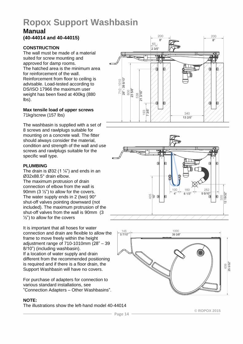
Ropox Support Washbasin Manual (40-44014 and 40-44015) CONSTRUCTION The wall must be made of a material suited for screw mounting and approved for damp rooms. The hatched area is the minimum area for reinforcement of the wall. Reinforcement from floor to ceiling is advisable. Load-tested according to DS/ISO 17966 the maximum user weight has been fixed at 400kg (880 lbs). Max tensile load of upper screws 71kg/screw (157 lbs) The washbasin is supplied with a set of 8 screws and rawlplugs suitable for mounting on a concrete wall. The fitter should always consider the material, condition and strength of the wall and use screws and rawlplugs suitable for the specific wall type. PLUMBING The drain is Ø32 (1 ¼”) and ends in an Ø32x88.5° drain elbow. The maximum protrusion of drain connection of elbow from the wall is 90mm (3 ½”) to allow for the covers. The water supply ends in 2 (two) 90° shut-off valves pointing downward (not included). The maximum protrusion of the shut-off valves from the wall is 90mm (3 ½”) to allow for the covers It is important that all hoses for water connection and drain are flexible to allow the frame to move freely within the height adjustment range of 710-1010mm (28” – 39 8/10”) (including washbasin). If a location of water supply and drain different from the recommended positioning is required and if there is a floor drain, the Support Washbasin will have no covers. For purchase of adapters for connection to various standard installations, see ”Connection Adapters – Other Washbasins”. NOTE: The illustrations show the left-hand model 40-44014

Page 15
© ROPOX 2015
Ropox Support Washbasin Electric left (40-44016) CONSTRUCTION The wall must be made of a material suited for screw mounting and approved for damp rooms. The hatched area is the minimum area for reinforcement of the wall. Reinforcement from floor to ceiling is advisable. Load-tested according to DS/ISO 17966 the maximum user weight has been fixed at 520kg (1144 lbs). Max. tensile load of upper screws 71kg/screw (157lbs). The washbasin is supplied with a set of 8 screws and rawlplugs suitable for mounting on a concrete wall. The fitter should always consider the material, condition and strength of the wall and use screws and rawlplugs suitable for the specific wall type. PLUMBING The drain is Ø32 (1 ¼”) and ends in an Ø32x88.5° drain elbow. The maximum protrusion of drain connection and elbow from the wall is 90mm (3 ½”) to allow for the covers. The water supply ends in 2 (two) 90° shut-off valves with ½” outside thread pointing downward (not included).The maximum protrusion of the shut-off valves from the wall is 90mm (3 ½”) to allow for the covers. Location and optimum orientation as shown in blue for water supply and in green for drain. It is important that all hoses for water connection and drain are flexible to allow the frame to move freely within the height-adjustment range of 710-960mm (28” – 37 4/5”) (including washbasin). If a location of water supply and drain different from the recommended positioning is required or if there is a floor drain, the Support Washbasin has no covers. For purchase of adapters for connection to various standard installations, see ”Connection Adapters – Other Washbasins”. POWER Recommended location of socket in wall for optimum and hidden wiring is shown in red. If a different location is required, the cable from the control unit is 3200mm (126”).
Page 16
© ROPOX 2015
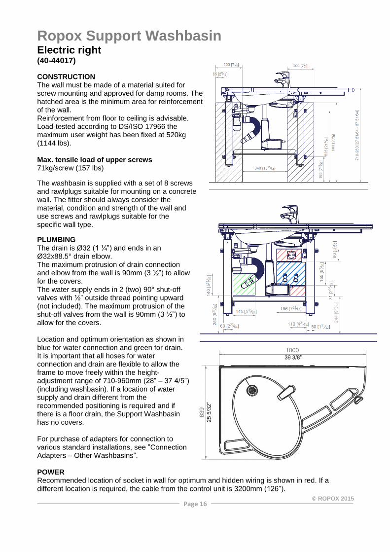
Ropox Support Washbasin Electric right (40-44017) CONSTRUCTION The wall must be made of a material suited for screw mounting and approved for damp rooms. The hatched area is the minimum area for reinforcement of the wall. Reinforcement from floor to ceiling is advisable. Load-tested according to DS/ISO 17966 the maximum user weight has been fixed at 520kg (1144 lbs). Max. tensile load of upper screws 71kg/screw (157 lbs) The washbasin is supplied with a set of 8 screws and rawlplugs suitable for mounting on a concrete wall. The fitter should always consider the material, condition and strength of the wall and use screws and rawlplugs suitable for the specific wall type. PLUMBING The drain is Ø32 (1 ¼”) and ends in an Ø32x88.5° drain elbow. The maximum protrusion of drain connection and elbow from the wall is 90mm (3 ½”) to allow for the covers. The water supply ends in 2 (two) 90° shut-off valves with ½” outside thread pointing upward (not included). The maximum protrusion of the shut-off valves from the wall is 90mm (3 ½”) to allow for the covers. Location and optimum orientation as shown in blue for water connection and green for drain. It is important that all hoses for water connection and drain are flexible to allow the frame to move freely within the height-adjustment range of 710-960mm (28” – 37 4/5”) (including washbasin). If a location of water supply and drain different from the recommended positioning is required and if there is a floor drain, the Support Washbasin has no covers. For purchase of adapters for connection to various standard installations, see ”Connection Adapters – Other Washbasins”. POWER Recommended location of socket in wall for optimum and hidden wiring is shown in red. If a different location is required, the cable from the control unit is 3200mm (126”).

Page 17
© ROPOX 2015
Ropox Support Washbasin
Optional: Sideways slide for Ropox Support Washbasin (40-44030) CONSTRUCTION The wall must be made of a material suited for screw mounting and approved for damp rooms. The hatched area is the minimum area for reinforcement of the wall. Reinforcement from floor to ceiling is advisable. Load-tested according to DS/ISO 17966 the maximum user weight has been fixed at 400kg (880 lbs). Max. tensile load of upper screws 41kg/screw (90 lbs)
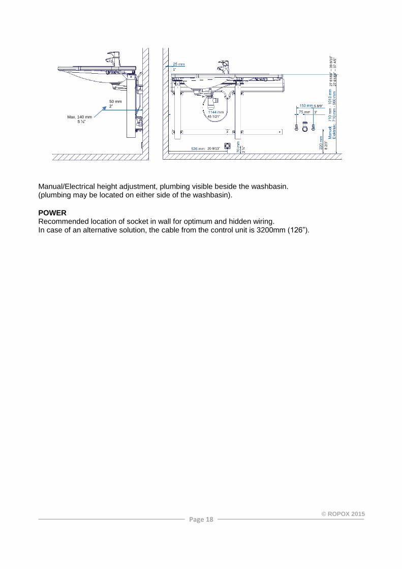
PLUMBING The drain has a diameter of Ø32 (1 ¼”) and is provided with an Ø32x88.5° elbow. Max. protrusion of drain connection and elbow from the wall is 140mm (5 ½”) owing to the covers. The water supply ends in 2 (two) 90° shut-off valves with ½” outside thread. Location and optimum orientation as illustrated. Max. protrusion of shut-off valves from the wall is 140mm (5 ½”) owing to the covers. It is recommended to install water and drain connections as illustrated. All hoses for water and drain connections must be flexible for the unit to move freely within the range of adjustment. Manual/electrical height adjustment, plumbing located behind the cover.
27 5
/9”
42 3/4”
20 9/13”
18 3/4”
4”
2”
2 ¾
”
1”
9 4/
9”
28” –
39
8/10
” 28
” – 3
7 4/
5”
50 mm 2”
Max. 140 mm 5 ½”
Page 18
© ROPOX 2015
Manual/Electrical height adjustment, plumbing visible beside the washbasin. (plumbing may be located on either side of the washbasin). POWER Recommended location of socket in wall for optimum and hidden wiring. In case of an alternative solution, the cable from the control unit is 3200mm (126”).
50 mm 2”
1”
20 9/13”
2 ¾
”
8 2/
3”
Max. 140 mm 5 ½”
45 1/21”
5 8/9”
3”
27 6
1/64
” – 3
9 8/
10”
27 6
1/64
” – 3
7 4/
5”

Page 19
© ROPOX 2015
Ropox VanityLine Washbasin
Manuel 60cm (40-14871) CONSTRUCTION The wall must be made of a material suited for screw mounting and approved for damp rooms. The hatched area is the minimum area for reinforcement of the wall. Reinforcement from floor to ceiling is advisable. Tested according to DS/ISO 17966:2016, and the maximum user weight has been fixed at 265kg (583 lbs). Max. tensile load of upper screws 78kg/screw (172 lbs) The washbasin is supplied with a set of 8 screws and rawlplugs suitable for mounting on a concrete wall. The fitter should always consider the material, condition and strength of the wall and use screws and rawlplugs suitable for the specific wall type. PLUMBING The drain is Ø32 (1 ¼”) and ends in an Ø32x88.5° drain elbow. The water supply ends in 2 (two) 90° shut-off valves with ½” outside thread pointing downwards (not included). The maximum protrusion of the shut-off valves and drain connection should be max 90mm (3 ½”) to allow for the covers. The optimum location and orientation is as shown in blue. It is important that all hoses for water connection and drain are flexible to allow the frame to move freely within the height-adjustment range of 680-980mm (26 3/4” – 38 1/2”) (including washbasin). If a different location of water supply from the recommended positioning is required and if there is a floor drain, the VanityLine can’t have installation covers. For purchase of adapters for connection to various standard installations, see ”Connection Adapters – Other Washbasins”.
Page 20
© ROPOX 2015
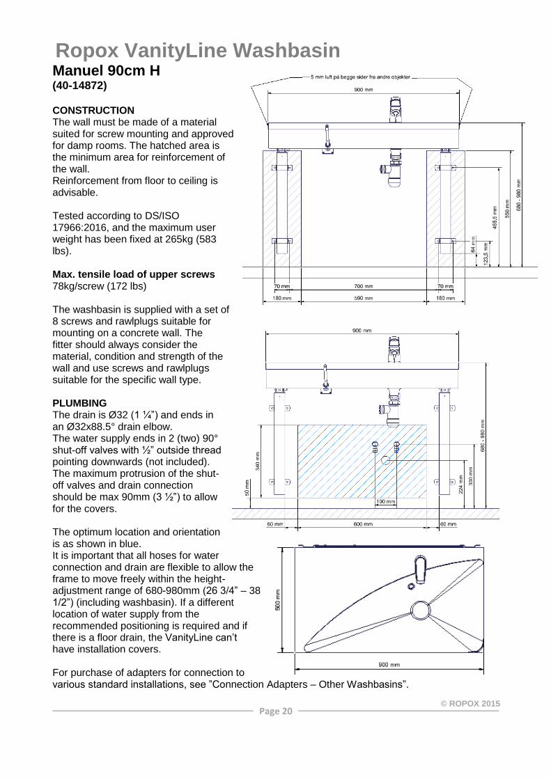
Ropox VanityLine Washbasin Manuel 90cm H (40-14872) CONSTRUCTION The wall must be made of a material suited for screw mounting and approved for damp rooms. The hatched area is the minimum area for reinforcement of the wall. Reinforcement from floor to ceiling is advisable. Tested according to DS/ISO 17966:2016, and the maximum user weight has been fixed at 265kg (583 lbs). Max. tensile load of upper screws 78kg/screw (172 lbs) The washbasin is supplied with a set of 8 screws and rawlplugs suitable for mounting on a concrete wall. The fitter should always consider the material, condition and strength of the wall and use screws and rawlplugs suitable for the specific wall type. PLUMBING The drain is Ø32 (1 ¼”) and ends in an Ø32x88.5° drain elbow. The water supply ends in 2 (two) 90° shut-off valves with ½” outside thread pointing downwards (not included). The maximum protrusion of the shut-off valves and drain connection should be max 90mm (3 ½”) to allow for the covers. The optimum location and orientation is as shown in blue. It is important that all hoses for water connection and drain are flexible to allow the frame to move freely within the height-adjustment range of 680-980mm (26 3/4” – 38 1/2”) (including washbasin). If a different location of water supply from the recommended positioning is required and if there is a floor drain, the VanityLine can’t have installation covers. For purchase of adapters for connection to various standard installations, see ”Connection Adapters – Other Washbasins”.
Page 21
© ROPOX 2015
Ropox VanityLine Washbasin
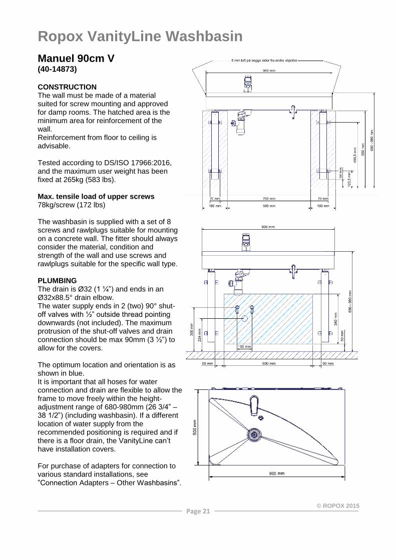
Manuel 90cm V (40-14873) CONSTRUCTION The wall must be made of a material suited for screw mounting and approved for damp rooms. The hatched area is the minimum area for reinforcement of the wall. Reinforcement from floor to ceiling is advisable. Tested according to DS/ISO 17966:2016, and the maximum user weight has been fixed at 265kg (583 lbs). Max. tensile load of upper screws 78kg/screw (172 lbs) The washbasin is supplied with a set of 8 screws and rawlplugs suitable for mounting on a concrete wall. The fitter should always consider the material, condition and strength of the wall and use screws and rawlplugs suitable for the specific wall type. PLUMBING The drain is Ø32 (1 ¼”) and ends in an Ø32x88.5° drain elbow. The water supply ends in 2 (two) 90° shut-off valves with ½” outside thread pointing downwards (not included). The maximum protrusion of the shut-off valves and drain connection should be max 90mm (3 ½”) to allow for the covers. The optimum location and orientation is as shown in blue. It is important that all hoses for water connection and drain are flexible to allow the frame to move freely within the height-adjustment range of 680-980mm (26 3/4” – 38 1/2”) (including washbasin). If a different location of water supply from the recommended positioning is required and if there is a floor drain, the VanityLine can’t have installation covers. For purchase of adapters for connection to various standard installations, see ”Connection Adapters – Other Washbasins”.

Page 22
© ROPOX 2015
Ropox VanityLine Washbasin Manuel 120cm H (40-14874) CONSTRUCTION The wall must be made of a material suited for screw mounting and approved for damp rooms. The hatched area is the minimum area for reinforcement of the wall. Reinforcement from floor to ceiling is advisable. Tested according to DS/ISO 17966:2016, and the maximum user weight has been fixed at 265kg (583 lbs). Max. tensile load of upper screws 78kg/screw (172 lbs) The washbasin is supplied with a set of 8 screws and rawlplugs suitable for mounting on a concrete wall. The fitter should always consider the material, condition and strength of the wall and use screws and rawlplugs suitable for the specific wall type. PLUMBING The drain is Ø32 (1 ¼”) and ends in an Ø32x88.5° drain elbow. The water supply ends in 2 (two) 90° shut-off valves with ½” outside thread pointing downwards (not included). The maximum protrusion of the shut-off valves and drain connection should be max 90mm (3 ½”) to allow for the covers. The optimum location and orientation is as shown in blue. It is important that all hoses for water connection and drain are flexible to allow the frame to move freely within the height-adjustment range of 680-980mm (26 3/4” – 38 1/2”) (including washbasin). If a different location of water supply from the recommended positioning is required and if there is a floor drain, the VanityLine can’t have installation covers. For purchase of adapters for connection to various standard installations, see ”Connection Adapters – Other Washbasins”.

Page 23
© ROPOX 2015
Ropox VanityLine Washbasin Manuel 120cm V (40-14875) CONSTRUCTION The wall must be made of a material suited for screw mounting and approved for damp rooms. The hatched area is the minimum area for reinforcement of the wall. Reinforcement from floor to ceiling is advisable. Tested according to DS/ISO 17966:2016, and the maximum user weight has been fixed at 265kg (583 lbs). Max. tensile load of upper screws 78kg/screw (172 lbs) The washbasin is supplied with a set of 8 screws and rawlplugs suitable for mounting on a concrete wall. The fitter should always consider the material, condition and strength of the wall and use screws and rawlplugs suitable for the specific wall type. PLUMBING The drain is Ø32 (1 ¼”) and ends in an Ø32x88.5° drain elbow. The water supply ends in 2 (two) 90° shut-off valves with ½” outside thread pointing downwards (not included). The maximum protrusion of the shut-off valves and drain connection should be max 90mm (3 ½”) to allow for the covers. The optimum location and orientation is as shown in blue. It is important that all hoses for water connection and drain are flexible to allow the frame to move freely within the height-adjustment range of 680-980mm (26 3/4” – 38 1/2”) (including washbasin). If a different location of water supply from the recommended positioning is required and if there is a floor drain, the VanityLine can’t have installation covers. For purchase of adapters for connection to various standard installations, see ”Connection Adapters – Other Washbasins”.
Page 24
© ROPOX 2015
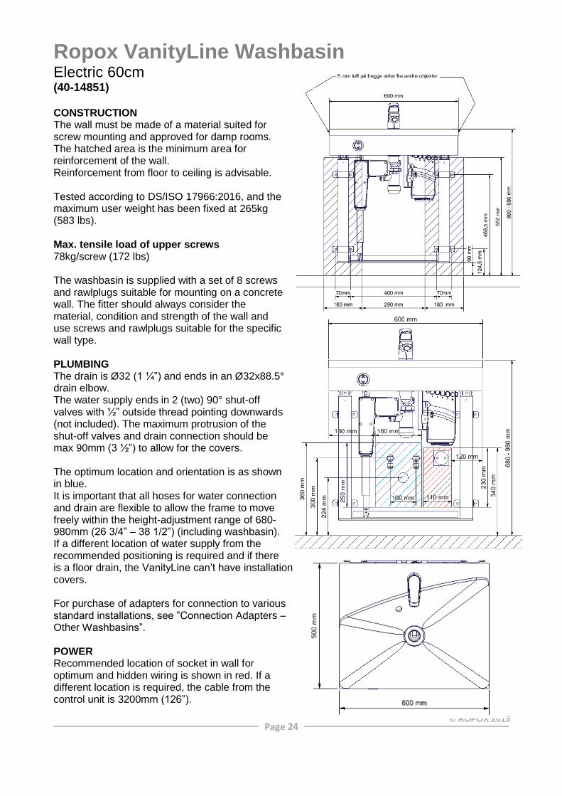
Ropox VanityLine Washbasin Electric 60cm (40-14851) CONSTRUCTION The wall must be made of a material suited for screw mounting and approved for damp rooms. The hatched area is the minimum area for reinforcement of the wall. Reinforcement from floor to ceiling is advisable. Tested according to DS/ISO 17966:2016, and the maximum user weight has been fixed at 265kg (583 lbs). Max. tensile load of upper screws 78kg/screw (172 lbs) The washbasin is supplied with a set of 8 screws and rawlplugs suitable for mounting on a concrete wall. The fitter should always consider the material, condition and strength of the wall and use screws and rawlplugs suitable for the specific wall type. PLUMBING The drain is Ø32 (1 ¼”) and ends in an Ø32x88.5° drain elbow. The water supply ends in 2 (two) 90° shut-off valves with ½” outside thread pointing downwards (not included). The maximum protrusion of the shut-off valves and drain connection should be max 90mm (3 ½”) to allow for the covers. The optimum location and orientation is as shown in blue. It is important that all hoses for water connection and drain are flexible to allow the frame to move freely within the height-adjustment range of 680-980mm (26 3/4” – 38 1/2”) (including washbasin). If a different location of water supply from the recommended positioning is required and if there is a floor drain, the VanityLine can’t have installation covers. For purchase of adapters for connection to various standard installations, see ”Connection Adapters – Other Washbasins”. POWER Recommended location of socket in wall for optimum and hidden wiring is shown in red. If a different location is required, the cable from the control unit is 3200mm (126”).

Page 25
© ROPOX 2015
Ropox VanityLine Washbasin Electric 90cm H (40-14852) CONSTRUCTION The wall must be made of a material suited for screw mounting and approved for damp rooms. The hatched area is the minimum area for reinforcement of the wall. Reinforcement from floor to ceiling is advisable. Tested according to DS/ISO 17966:2016, and the maximum user weight has been fixed at 265kg (583 lbs). Max. tensile load of upper screws 78kg/screw (172 lbs) The washbasin is supplied with a set of 8 screws and rawlplugs suitable for mounting on a concrete wall. The fitter should always consider the material, condition and strength of the wall and use screws and rawlplugs suitable for the specific wall type. PLUMBING The drain is Ø32 (1 ¼”) and ends in an Ø32x88.5° drain elbow. The water supply ends in 2 (two) 90° shut-off valves with ½” outside thread pointing downwards (not included). The maximum protrusion of the shut-off valves and drain connection should be max 90mm (3 ½”) to allow for the covers. The optimum location and orientation is as shown in blue. It is important that all hoses for water connection and drain are flexible to allow the frame to move freely within the height-adjustment range of 680-980mm (26 3/4” – 38 1/2”) (including washbasin). If a different location of water supply from the recommended positioning is required and if there is a floor drain, the VanityLine can’t have installation covers. For purchase of adapters for connection to various standard installations, see ”Connection Adapters – Other Washbasins”. POWER Recommended location of socket in wall for optimum and hidden wiring is shown in red. If a different location is required, the cable from the control unit is 3200mm (126”).
Page 26
© ROPOX 2015
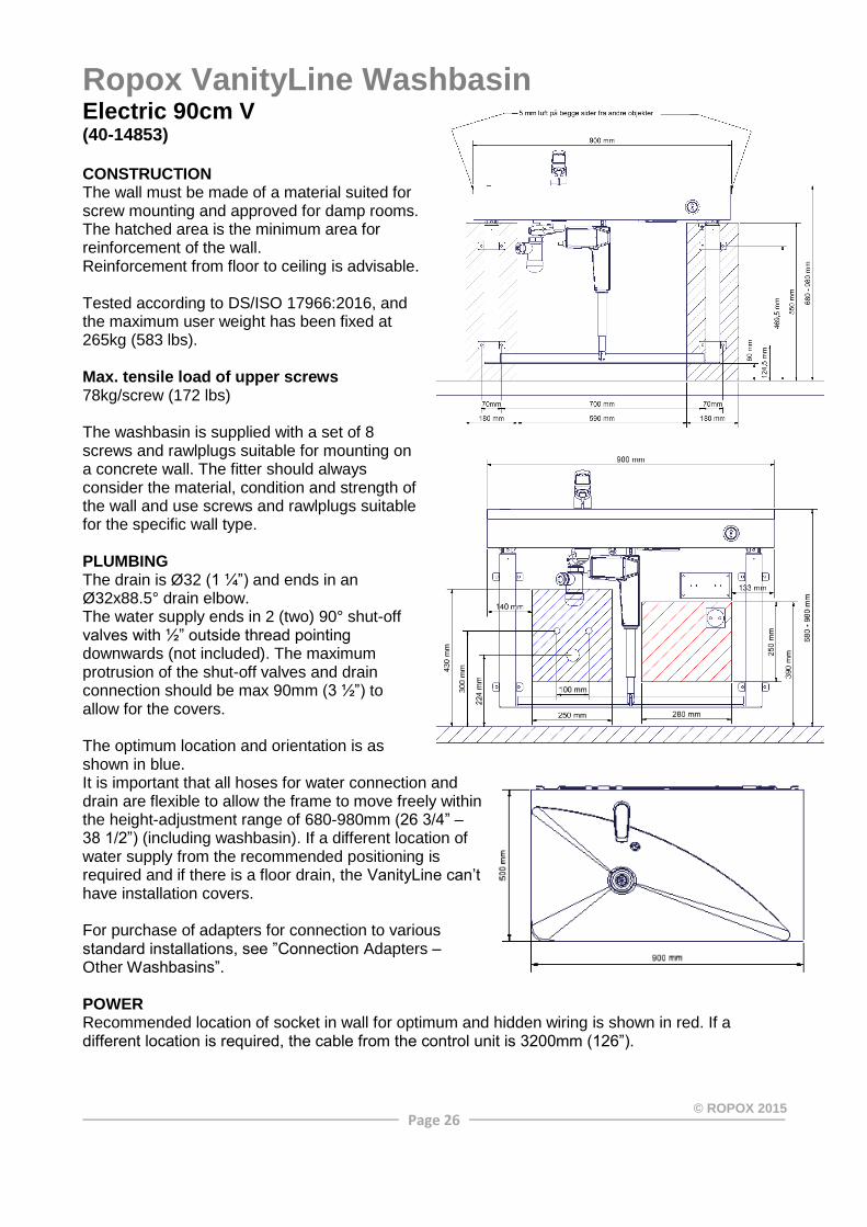
Ropox VanityLine Washbasin Electric 90cm V (40-14853) CONSTRUCTION The wall must be made of a material suited for screw mounting and approved for damp rooms. The hatched area is the minimum area for reinforcement of the wall. Reinforcement from floor to ceiling is advisable. Tested according to DS/ISO 17966:2016, and the maximum user weight has been fixed at 265kg (583 lbs). Max. tensile load of upper screws 78kg/screw (172 lbs) The washbasin is supplied with a set of 8 screws and rawlplugs suitable for mounting on a concrete wall. The fitter should always consider the material, condition and strength of the wall and use screws and rawlplugs suitable for the specific wall type. PLUMBING The drain is Ø32 (1 ¼”) and ends in an Ø32x88.5° drain elbow. The water supply ends in 2 (two) 90° shut-off valves with ½” outside thread pointing downwards (not included). The maximum protrusion of the shut-off valves and drain connection should be max 90mm (3 ½”) to allow for the covers. The optimum location and orientation is as shown in blue. It is important that all hoses for water connection and drain are flexible to allow the frame to move freely within the height-adjustment range of 680-980mm (26 3/4” – 38 1/2”) (including washbasin). If a different location of water supply from the recommended positioning is required and if there is a floor drain, the VanityLine can’t have installation covers. For purchase of adapters for connection to various standard installations, see ”Connection Adapters – Other Washbasins”. POWER Recommended location of socket in wall for optimum and hidden wiring is shown in red. If a different location is required, the cable from the control unit is 3200mm (126”).

Page 27
© ROPOX 2015
Ropox VanityLine Washbasin
Electric 120cm H (40-14854) CONSTRUCTION The wall must be made of a material suited for screw mounting and approved for damp rooms. The hatched area is the minimum area for reinforcement of the wall. Reinforcement from floor to ceiling is advisable. Tested according to DS/ISO 17966:2016, and the maximum user weight has been fixed at 265kg (583 lbs). Max. tensile load of upper screws 78kg/screw (172 lbs) The washbasin is supplied with a set of 8 screws and rawlplugs suitable for mounting on a concrete wall. The fitter should always consider the material, condition and strength of the wall and use screws and rawlplugs suitable for the specific wall type. PLUMBING The drain is Ø32 (1 ¼”) and ends in an Ø32x88.5° drain elbow. The water supply ends in 2 (two) 90° shut-off valves with ½” outside thread pointing downwards (not included). The maximum protrusion of the shut-off valves and drain connection should be max 90mm (3 ½”) to allow for the covers. The optimum location and orientation is as shown in blue. It is important that all hoses for water connection and drain are flexible to allow the frame to move freely within the height-adjustment range of 680-980mm (26 3/4” – 38 1/2”) (including washbasin). If a different location of water supply from the recommended positioning is required and if there is a floor drain, the VanityLine can’t have installation covers. For purchase of adapters for connection to various standard installations, see ”Connection Adapters – Other Washbasins”. POWER Recommended location of socket in wall for optimum and hidden wiring is shown in red. If a different location is required, the cable from the control unit is 3200mm (126”).

Page 28
© ROPOX 2015
Ropox VanityLine Washbasin Electric 120cm V (40-14855) CONSTRUCTION The wall must be made of a material suited for screw mounting and approved for damp rooms. The hatched area is the minimum area for reinforcement of the wall. Reinforcement from floor to ceiling is advisable. Tested according to DS/ISO 17966:2016, and the maximum user weight has been fixed at 265kg (583 lbs). Max. tensile load of upper screws 78kg/screw (172 lbs) The washbasin is supplied with a set of 8 screws and rawlplugs suitable for mounting on a concrete wall. The fitter should always consider the material, condition and strength of the wall and use screws and rawlplugs suitable for the specific wall type. PLUMBING The drain is Ø32 (1 ¼”) and ends in an Ø32x88.5° drain elbow. The water supply ends in 2 (two) 90° shut-off valves with ½” outside thread pointing downwards (not included). The maximum protrusion of the shut-off valves and drain connection should be max 90mm (3 ½”) to allow for the covers. The optimum location and orientation is as shown in blue. It is important that all hoses for water connection and drain are flexible to allow the frame to move freely within the height-adjustment range of 680-980mm (26 3/4” – 38 1/2”) (including washbasin). If a different location of water supply from the recommended positioning is required and if there is a floor drain, the VanityLine can’t have installation covers. For purchase of adapters for connection to various standard installations, see ”Connection Adapters – Other Washbasins”. POWER Recommended location of socket in wall for optimum and hidden wiring is shown in red. If a different location is required, the cable from the control unit is 3200mm (126”).

Page 29
© ROPOX 2015
Ropox SlimLine Washbasin
Electric (40-15601, 40-15605, 40-15607) CONSTRUCTION The wall must be made of a material suited for screw mounting and approved for damp rooms. The hatched area is the minimum area for reinforcement of the wall. Tested in accordance with DS/EN 12182:2012 and DS/ISO 17966:2016 with the following max. user weights: 40-15601: 165kg (363 lbs) 40-15605: 120kg (265 lbs) 40-15607: 200kg (440 lbs) (when using a porcelain wash basin) Max. tensile load of upper screws 68kg/screw (150 lbs) The washbasin is supplied with a set of screws and rawlplugs suitable for mounting on a concrete wall. The fitter should always consider the material, condition and strength of the wall and use screws and rawlplugs suitable for the specific wall type. PLUMBING The drain is Ø32 (1 ¼”) and ends in an Ø32x88.5° drain elbow. The water supply ends in 2 (two) 90° shut-off valves with ½” outside thread pointing downwards in an angle of 45° (not included). The maximum protrusion of the shut-off valves and drain connection should be max 77mm (3”) to allow for the covers. The optimum location and orientation is as shown. It is important that all hoses for water connection and drain are flexible to allow the frame to move freely within the height-adjustment range of 700-1000mm (27 1/2” – 39 2/5”) (including washbasin). If a different location of water supply from the recommended positioning is required and if there is a floor drain, the installation cover (40-15610) can’t be used. For purchase of adapters for connection to various standard installations, see ”Connection Adapters – Other Washbasins”. POWER Recommended location of socket in wall for optimum and hidden wiring is above unit as shown. The cable from the control unit is 2000mm (78”).

Page 30
© ROPOX 2015
Ropox StandardLine Washbasin
Electric (40-14770, 40-14772 og 40-14773) CONSTRUCTION The wall must be made of a material suited for screw mounting and approved for damp rooms. The hatched area is the minimum area for reinforcement of the wall. Tested in accordance DS/ISO 17966:2016 with the following max. user weights: 40-14772: 200kg (440 lbs) 40-14773: 200kg (440 lbs) 40-14770: 200kg (440 lbs) (when using a porcelain wash basin) Max. tensile load of upper screws 50kg/screw (110 lbs) The washbasin is supplied with a set of screws and rawlplugs suitable for mounting on a concrete wall. The fitter should always consider the material, condition and strength of the wall and use screws and rawlplugs suitable for the specific wall type. PLUMBING The drain is Ø32 (1 ¼”) and ends in an Ø32x88.5° drain elbow. The water supply ends in 2 (two) 90° shut-off valves with ½” outside thread pointing upwards (not included). The maximum protrusion of the shut-off valves and drain connection should be max 90mm (3 ½”) to allow for the covers. The optimum location and orientation is as shown in green. It is important that all hoses for water connection and drain are flexible to allow the frame to move freely within the height-adjustment range of 700-1000mm (27 1/2” – 39 2/5”) (including washbasin). For purchase of adapters for connection to various standard installations, see ”Connection Adapters – Other Washbasins”. POWER Recommended location of socket in wall for optimum and hidden wiring is shown in red. If a different location is required, the cable from the control unit is 3200mm (126”).

Page 31
© ROPOX 2015
Ropox AdaptLine Washbasin
Manual (40-42110, 40-42011 og 40-42012) CONSTRUCTION The wall must be made of a material suited for screw mounting and approved for damp rooms. The hatched area is the minimum area for reinforcement of the wall. Tested in accordance with DS/ISO 17966:2016 with the following max. user weights: 40-42011: 165kg (363 lbs) 40-42012: 120kg (264 lbs) 40-42110: 200kg (264 lbs) (when using a porcelain wash basin) Max. tensile load of upper screws 62kg/screw (137 lbs) The washbasin is supplied with a set of screws and rawlplugs suitable for mounting on a concrete wall. The fitter should always consider the material, condition and strength of the wall and use screws and rawlplugs suitable for the specific wall type. PLUMBING The drain is Ø32 (1 ¼”) and ends in an Ø32x88.5° drain elbow. The water supply ends in 2 (two) 90° shut-off valves with ½” outside thread pointing downwards (not included). The optimum location and orientation is as shown. It is important that all hoses for water connection and drain are flexible to allow the frame to move freely within the height-adjustment range of 700-900mm (27 1/2” – 35 2/5”) (including washbasin). For purchase of adapters for connection to various standard installations, see ”Connection Adapters – Other Washbasins”.

Page 40
© ROPOX 2015
Connection Adapters – Other Washbasins
The components illustrated below are available as optional extras depending on the type of installation in the building. Water supply adapters
Hoses from wash basin Adapters Installation in
room (not included)
No adapter required
1/2" thread
1/2" -> 3/8" Item No. 97001670
3/8" thread
1/2" -> 15mm Item No. 97001666
15mm pipe
Water hose extensions Hose from washbasin Coupling piece Extra hose
1/2" -> 1/2" Item No. 97001669
1/2" x 1/2", 0,5m (19,7”), steel Item No. 97001123
1/2" x 1/2", 1m (39,4”), plastic Item No. 97001120
Drain adapters
Drain from wash basin Adapter Installation in
room (not provided)
No adapter required Ø32 (1 ¼”)
Ø32 -> Ø40 Item No. 97001660
Ø40 (1 ½”)
Ø32 -> Ø50
Item No. 97001661
Ø50 (2”)
Drain extensions Drain hose from wash basin Coupling piece Extra drain hose
Ø32-Ø32 Item No. 97001062
Ø32 Flex hose, 27-62cm (10,6”-24,4”) Item No. 97001162
Ø32 Flex hose, 40-110cm (15,7”-43,3”) Item No. 97001161
1/2”
Ø32 (1 ¼”)
Ø32 (1 ¼”)
1/2”

Page 41
© ROPOX 2015