roll (direct and reverse) - kap cor bullet/application methods-coating failures... · higher film...
TRANSCRIPT


� Roll (direct and reverse)
� In direct roll coating, the applicator roll rotates in the same direction as the substrate moves. In reverse roll coating, metal feed stock is fed between the rolls as a continuous coil. The between the rolls as a continuous coil. The applicator roll rotates in the opposite direction of the substrate.

� Dip refers to immersing a piece into a tank containing the coating material, removing the piece from the tank, and allowing it to drain. The coated piece can then be dried by force-drying or baking.drying or baking.
� Dipping is extremely dependent on the viscosity of the coating, is very messy, and may be highly hazardous. The viscosity of the paint in a dip tank must remain practically constant if the deposited film quality is to remain high.

� In flow, the part is suspended, and the coating is poured over it. The excess material drips off and is collected for reuse.
� Flow is usually used for large or oddly shaped parts that are difficult or impossible to shaped parts that are difficult or impossible to dip coat. Coatings applied by flow coating have only a poor to fair appearance unless the parts are rotated while dripping.

� In dip-spin, a wire basket containing up to 50 pounds of parts is immersed in a reservoir of paint. The basket is raised, the parts are allowed to drain, the basket is spun to remove excess paint, and the parts are dumped onto a mesh conveyer belt, then moved through a bake oven. The entire process is automatic. The main advantage is the extremely high production rate. extremely high production rate.
� Dip-spin coaters are designed to paint large-quantity batch loads of small parts, such as hairpins, clips, and fasteners.
� Some of the painted parts dumped on the conveyer may stick together in the oven, leaving paint voids when they are separated. These parts may be run through the process a second time to eliminate the defects.


� Airless paint sprayers are designed to cover large surfaces quickly. The tip size used in the spray gun determines the type of coating possible. Tip and motor size will dictate speed of coverage.
� It can deliver twice the amount of material as a compressed air system. This allows airless guns to be compressed air system. This allows airless guns to be used advantageously on high-speed production lines or where surface areas are large.
� Transfer efficiency is higher than conventional spray because of reduced fog and overspray. The absence of blow air associated with the gun simplifies application.

Example

� Overspray and bounce back reduced
� Higher film build up
� Faster production
� No control over fan size which regulated by tip size
� On or Off no � Faster production
rates
� Compress air not used for atomization
� Air, gas powered, electric units.
� On or Off no feathering possible
� Difficult to coat small intricate parts
� Tips wear out relatively fast

Spray Distance 10” – 16”

� Conventional air spray is the oldest spray process. It offers the best control of spray patterns and degree of atomization. This system produces the finest atomization and, therefore, the finest finishes. Conventional spray will also spray the widest range of coating materials of the four techniques.
� In conventional or air atomized spraying, the coating is supplied to a spray gun by siphon, gravity, or pressure
� In conventional or air atomized spraying, the coating is supplied to a spray gun by siphon, gravity, or pressure feed. When the gun trigger is pulled, the coating flows through the nozzle as a fluid stream. Compressed air from the center of the nozzle surrounds the fluid with a hollow cone as it leaves the nozzle, breaking the coating into small droplets and transferring velocity to it. Additional jets of compressed air from the nozzle break up the droplets further and form an elliptical pattern.


� Spray pattern is easily adjusted to any fan width
� High Quality finishes
� More over spray cause more material loss
� Turbulence caused � High Quality finishes � Turbulence caused by atomization air
� Usually requires solvent reduction –less DFT per coat

� HVLP is a type of air atomized spraying. HVLP guns operate at pressures of 0.1 to 10 psi at the air nozzle and use 15 to 30 cfm of air. However, there are many factors that affect overspray, most important of which is the manner in which the painter sets the air and fluid pressures, fan width, and gun-target distance. 416
� The low atomizing air pressure of an HVLP gun minimizes the amount of bounce-back paint fog and reduces the amount of atomized paint that is blown past a part as overspray. The higher transfer efficiency helps hold down operating costs by reducing paint waste. blown past a part as overspray. The higher transfer efficiency helps hold down operating costs by reducing paint waste.
� HVLP has a higher transfer efficiency than conventional air spray, up to 65 to 75 %. This results in lower material use (reduces costs), less spray booth maintenance and cleanup, and less hazardous waste.
� The droplet size is not as fine as conventional air atomization. To achieve good finish quality on some applications, additional polishing or coating reformulation may be necessary. However, if surface preparation is done properly, spray application should have good adhesion.

� High Volume Low Pressure spray systems use high volumes of air delivered at low
� Better controlled spray pattern
� Reduce bounce back
� Reduce overspraydelivered at low pressure to atomize the fluid into a soft low velocity system
� Reduce overspray
� Reduced VOC
� Better transfer efficiency
� Less hazardous waste

� The surface must be dry and in sound condition.
� Remove mildew, oil, dust, dirt, loose rust, peeling paint or other contamination to ensure good adhesion. good adhesion.
� No exterior painting should be done immediately after a rain, during foggy weather, when rain is predicted, or when the temperature is below the recommended temperature.
� See handout for more details.

� Inspection should be carried out at the following critical stages: � Inspection of steel to be used
� Inspection of applied shop primer
� Inspection of steel work (welding, cutting of edges) � Inspection of steel work (welding, cutting of edges)
� Inspection of surface preparation
� Inspection before and during application
� Inspection after application
� Rounding of sharp edges
� Smoothing of rough welding seams
� Removal/grinding of weld spatter and beads
� Cracks and pittings � Cracks and pittings
� Surface faults like laminations, etc.

� Inspection of surface preparation includes the following:
� Cleanliness; solvent cleaning to remove salt, oil, grease, and dust/dirtoil, grease, and dust/dirt
� Evaluation of present condition (rust grade)
� Evaluation of surface (preparation grade and roughness)
� Remaining contamination acceptable?

� Inspection during application should includes the following activities: � Climatic conditions � Technical Data Sheet must be available and followed � Ensure correct mixing and thinning (extremely
important) important) � Measuring the wet film thickness (WFT) � Number of coats as given in the specification � Cleanliness between coats (salts, dust, oil etc.) � Drying time between coats, minimum and maximum � The workmanship � Controlling the equipment and methods used

� Another critical stage that needs to be followed up is when the application has been finished. Inspection after completion of the application includes:
Dry film thickness (DFT) � Dry film thickness (DFT)
� Curing/drying
� Adhesion
� Holiday detection

� Improper stirring� Not enough or excessive millage� Surface contamination� Contamination in lines� Out of Shelf life� Out of Shelf life� Improper Air pressure� Hose or line too long� Too long between surface preparation and
prime� Wrong product for service

� Poor applicator training
� Poor quality control
� Lack of facilities to adjust environment
� Improper surface preparation� Improper surface preparation
� Specification non-compliance
� Recoat too quickly
� Too long between coats
� Improper storage

� Coating failures may appear during application, at the stage of curing or after a certain period of service life.
� Statistics show that as much as 95% of all coating failures is a result of poor surface preparation and application. Below you will find some examples of common coating Below you will find some examples of common coating failures and the reason why they occur. Please note that there may be many reasons for a coating failure and in some cases it requires a lot of experience to find the exact cause

� Sagging occurs when:
� Coating is applied in excess of the DFT excess of the DFT specified
� Too much thinner has been added to the paint
� The gun is held too close to the surface.

� Sags are recognized as "curtains" on the painted surfaces. If the wet film thickness is too high, excessive sagging can result in pools of paints forming on horizontal surfaces or in corners. After curing, the paint may crack all corners. After curing, the paint may crack all the way to the substrate in such areas and reveal unprotected steel.If sagging is noticed at the spraying stage, it should be brushed out while the paint film is still wet. Repairs after drying consists of abrasion (sanding) and re-coating

� Using the wrong spraying technique, such as excessive air pressure, excessive film thickness, strong wind (too good ventilation) and too long application distance may cause craters, pinholes and pores. If noticeable on the paint film, check the spraying equipment to ensure that the air pressure and nozzle size is correct. Pinholes in a paint film can also result from overspray. result from overspray.
� On excessive film thickness air will be entrapped in the paint. The escaping air will create pinholes. The consequence being that pinpoint rusting occurs, followed by undercutting of the coating around the pinholes. Repairs consist of grinding and re-coating the area using appropriate coats to seal the defects and build up the coating to the correct DFT. If the coating is still uncured, brush out and apply the additional coat

This is one of the most common types of failure related to the adhesion of the paint. Sometimes the blisters are dry and sometimes filled with liquid. The filled with liquid. The blisters can be both large and small, often shaped as hemispheres. The size usually depends on the degree of adhesion to the substrate, or between the coats, and the internal pressure of the gas or the liquid inside the blister.

� Poor or inadequate solvent release from the coating. Entrapped solvents can increase the water absorption and moisture vapour transmission of the coating and lead to blistering. Solvent odour is usually connected with retained solvents. If the blistering is widespread on a construction: reblast and wash before a new system is applied. For local areas: blast or carry out other mechanical cleaning before recoating.
� Soluble salts contaminating the substrate or contaminating the surface � Soluble salts contaminating the substrate or contaminating the surface between coats. No coatings are 100% water proof. The moisture vapour passing through the coating can dissolve salt into a concentrated solution. Pressure in the high concentration liquid will cause blisters. This phenomen is called osmosis.
� Contamination of the surface (e.g. oils, waxes, dust, etc.) will not allow proper adhesion of the coating. The moisture vapour tends to be concentrated in these areas of low adhesion. In this case, the blisters are so-called "dry" blisters.

� Lifting is a raising of the undercoat. It is caused by a stronger solvent in the topcoat attacking the previously applied film. The result is a wrinkled surface. surface.
� A typical example is a topcoat containing xylene, on top of an alkyd-based primer containing white spirit. The xylene in the topcoat will dissolve the primer.
� Blast cleaning and reapplication of the paint is necessary to repair the damaged surface.

� Loss of adhesion to the substrate or between coats of paint is delamination or peeling. The causes are:
� Unsatisfactory surface preparation preparation
� Incompatible primer or undercoat
� Substrate or intercoat contamination
� Excessive cure time between coats
� The way to repair the surface, is to remove paint down to sound paint or to the substrate, and recoat.

� Finely pebbled or dimpled surface texture with an appearance similar to the skin of an orange. Caused by:
� Improper atomization � Improper atomization due to excessive low air pressure
� Spraying too close to the surface
� Rapid solvent evaporation
� Orange peel is mainly a cosmetic defect; sand down to smooth surface and repaint if necessary.


� Through film breakdown most commonly occurs in the hullage space at the top of ballast tanks and tends to be common the tends to be common the under deck plating. In the picture, the coating breakdown shown is in the later stages of development, where the rust spots have grown due the warm and humid conditions found in these areas.

� Through film breakdown usually occurs first on the upper surfaces of longitudinal stiffeners (picture left) and on stringer decks (picture right), where residual water remains on both surfaces for longer periods after the tank is first emptied.
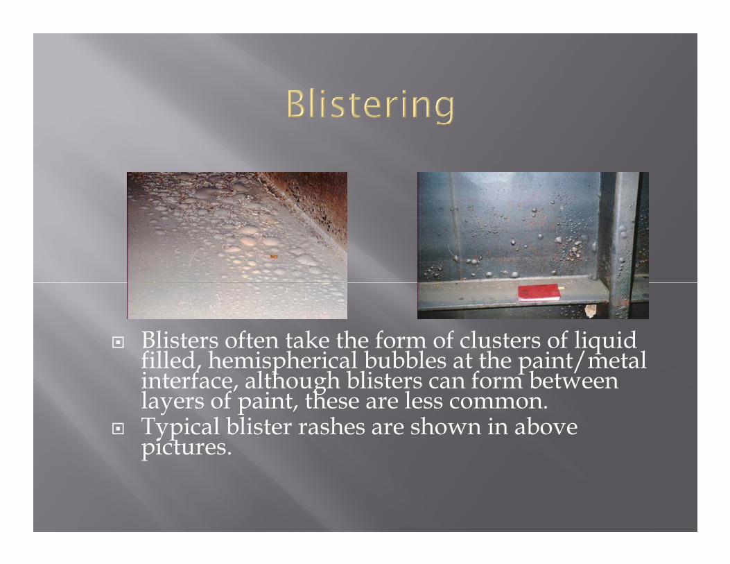
� Blisters often take the form of clusters of liquid filled, hemispherical bubbles at the paint/metal interface, although blisters can form between layers of paint, these are less common.
� Typical blister rashes are shown in above pictures.

� One of the areas to exhibit early coating breakdown is the edge of stiffeners (picture left) and around cut outs (picture right), which frequently fail through edge breakdown mechanisms.
� Often, special care is taken with the coating process in these areas. Edges can be ground smooth and stripe coats of paint applied by hand. Surface tension effects in the wet film, high coating velocity during spraying and poor local surface preparation are common caused of edge breakdown.

� Welds are susceptible to enhanced localized coating breakdown in the same manner as edges. Commonly, two types of weld corrosion occur. The first is illustrated in picture left, where corrosion initiates on either side of the weld bead in the area associated with oxide build up from the welding process.
� The second type of weld coating failure occurs much closer to the weld and is associated with poor surface cleanliness prior to coating. An example is given at picture right.
� Over thickness at the edges of the weld bead is also a contributing factor to weld corrosion. Weld spatter, (which takes the form of small beads of metal close to the weld) can cause micro-blistering if overcoated

� When the cathodic protection system is working well, the volume of the deposits is just sufficient to fill any cracks in the damaged area (left picture).
� When the anodes are overworked, then the voluminous deposits forming beneath the coating can lever it off the steel, as shown in (right picture).
� The presence of sacrificial anodes in ballast tanks induces the formation of hydroxyl ions at the coating/metal interface – which has the result of inhibiting or preventing corrosion from occurring beneath the coating. A side effect is that a white, chalky material (called effect is that a white, chalky material (called calcareous deposit) forms beneath the coating.
� The calcareous deposit originates partially from the reaction of carbon dioxide with the hydroxyl ions and partly as the result of semi-soluble carbonates being deposited from the sea water.

� The most common cause of coating failure is poor surface preparation. When the film is in good condition at thicknesses of greater than 250mm, micro-blistering results.blistering results.
� However, when the coating is either poorly applied or too thin, then failures of the type shown in picture right tend to occur. This is typically extensive corrosion breakthrough occurring in localized, clustered areas.

� A typical example is shown in the left picture, which illustrates the shatter patterns that result from the coating failing in a brittle manner.
� Reverse impact damage is also common in the shell plating, especially around tug contact areas and in the forepeak tank as a result of collisions with floating objects (right picture). This type of reverse impact damage are usually slower and result in distortion of the coating, which in turn leads to through film corrosion at the damaged site.

� Cracks in a typical pattern extend down from the surface of the coating and can reach the coating/metal interface. Mud cracking is generally a result of is generally a result of either a very high build up of coating or can be due to excessive thinning in conjunction with thick films. Often the interface with the steel is weakened and corrosion quickly initiates in the cracks.

� Corrosion can initiate at heavily stressed areas within tanks. Stress related coating failures can be recognized by can be recognized by their location or by the presence of the repetition of the same failure in the same place along the length of a structure, as shown in the picture.

� Often stress related failures can initiate at cut outs as shown in the left picture or at the toes of welds as shown in the right picture.
� Both stress and strain are causes of the coating failure. Stress concentrations can cause local anodic areas to develop, which then concentrates corrosion at that location. Strain can lead to cracking and disbonding of the coating, due to differences in mechanical properties between the coating and the underlying steel.

� Be sure the material you are using is adequate for the purpose intended. Proper testing of finished samples or pilot lots will offset future complaints.
� Make routine inspection of material for working properties before throwing on production line. This prevents shutdowns.
� Keep equipment in working order. Daily inspections should be made. Dip tanks should be checked for viscosity, gravity, performance; spray lines should be kept clear, etc.made. Dip tanks should be checked for viscosity, gravity, performance; spray lines should be kept clear, etc.
� Be sure that the product surface is properly cleaned and in suitable condition for painting.
� Reduce paint in accordance with manufacturer’s instructions. Strain reduced material into spray tank or other production line equipment.

� Practice routine inspection. Faulty production should be apprehended quickly to prevent accumulating rejects.
� Use good housekeeping measures. A clean shop produces clean work, and reduces lost time caused by accidents, fire, etc.
� Be aware that changes in weather often require � Be aware that changes in weather often require adjustments in handling procedure, such as change of reducer, drying time before packing, etc.
� Check on stock rotation. Use lots in order received, to prevent leaving extremely old materials in stock.
� In refilling leftover material, strain into clean containers, fill containers to the top, and close tightly so that there will be no air leakage into the package. Label and date.