outlineroger/569m/ch7.pdfoutline scalability • physical, bandwidth, latency and cost • level of...
TRANSCRIPT
1
2
Outline
Scalability
• physical, bandwidth, latency and cost
• level of integration
Realizing Programming Models
• network transactions
• protocols
• safety– input buffer problem: N-1
– fetch deadlock
Communication Architecture Design Space• how much hardware interpretation of the network transaction?
3
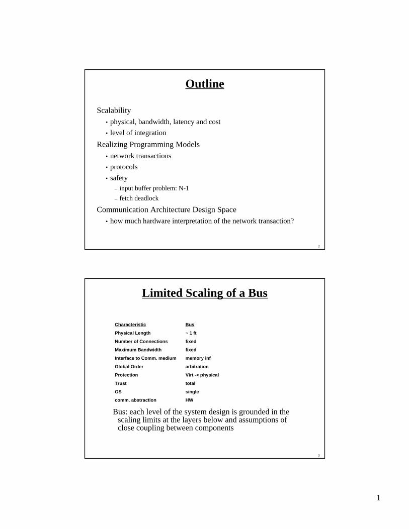
Limited Scaling of a Bus
Bus: each level of the system design is grounded in thescaling limits at the layers below and assumptions ofclose coupling between components
Characteristic Bus
Physical Length ~ 1 ft
Number of Connections fixed
Maximum Bandwidth fixed
Interface to Comm. medium memory inf
Global Order arbitration
Protection Virt -> physical
Trust total
OS single
comm. abstraction HW
2
4
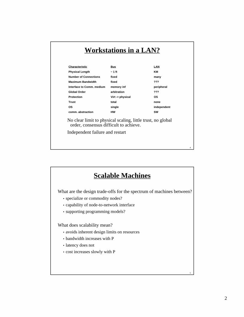
Workstations in a LAN?
No clear limit to physical scaling, little trust, no globalorder, consensus difficult to achieve.
Independent failure and restart
Characteristic Bus LAN
Physical Length ~ 1 ft KM
Number of Connections fixed many
Maximum Bandwidth fixed ???
Interface to Comm. medium memory inf peripheral
Global Order arbitration ???
Protection Virt -> physical OS
Trust total none
OS single independent
comm. abstraction HW SW
5
Scalable Machines
What are the design trade-offs for the spectrum of machines between?
• specialize or commodity nodes?
• capability of node-to-network interface
• supporting programming models?
What does scalability mean?
• avoids inherent design limits on resources
• bandwidth increases with P
• latency does not
• cost increases slowly with P
3
6
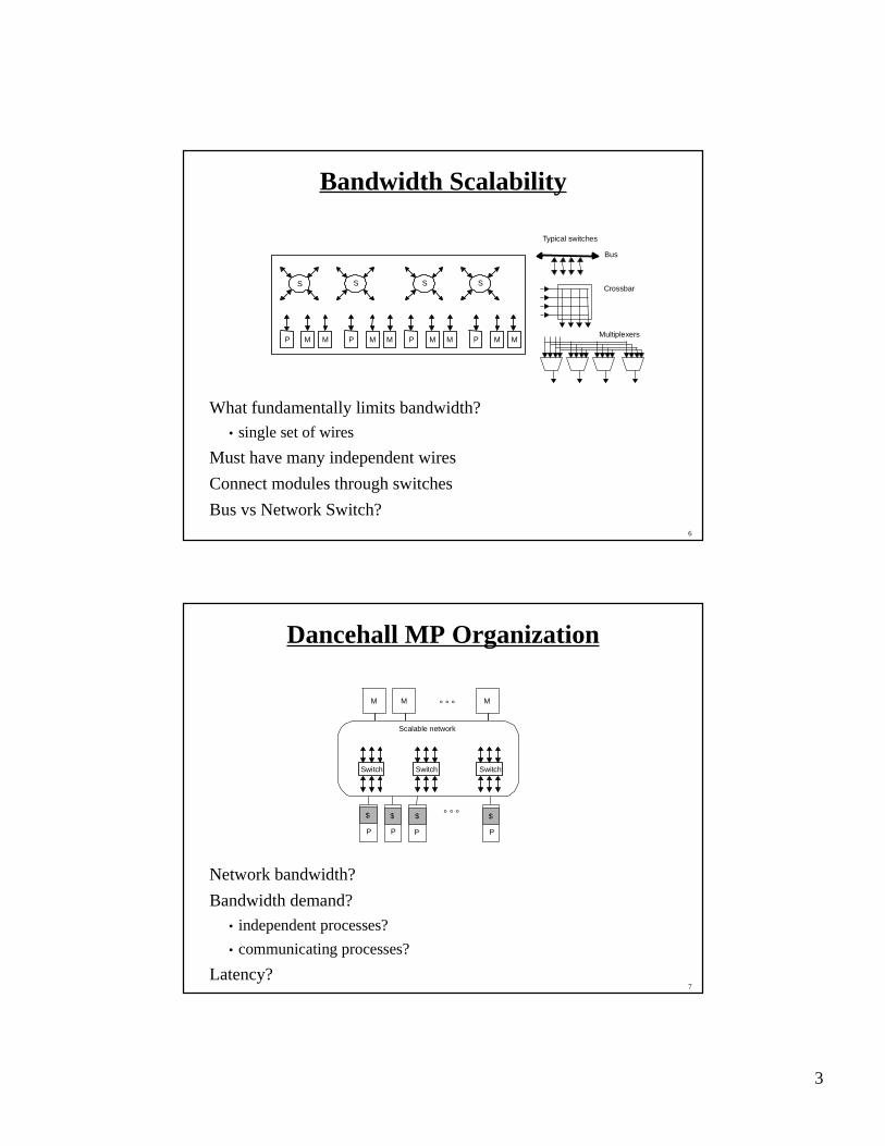
Bandwidth Scalability
What fundamentally limits bandwidth?• single set of wires
Must have many independent wires
Connect modules through switches
Bus vs Network Switch?
P M M P M M P M M P M M
S S S S
Typical switches
Bus
Multiplexers
Crossbar
7
Dancehall MP Organization
Network bandwidth?
Bandwidth demand?
• independent processes?
• communicating processes?
Latency?
° ° °
Scalable network
P
$
Switch
M
P
$
P
$
P
$
M M° ° °
Switch Switch
4
8
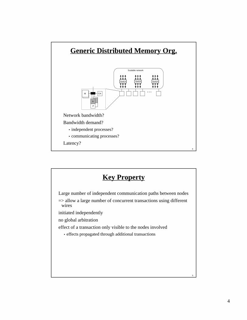
Generic Distributed Memory Org.
Network bandwidth?
Bandwidth demand?
• independent processes?
• communicating processes?
Latency?
° ° °
Scalable network
CA
P
$
Switch
M
Switch Switch
9
Key Property
Large number of independent communication paths between nodes
=> allow a large number of concurrent transactions using differentwires
initiated independently
no global arbitration
effect of a transaction only visible to the nodes involved
• effects propagated through additional transactions

5
10
Latency Scaling
T(n) = Overhead + Channel Time + Routing Delay
Overhead?
Channel Time(n) = n/B --- BW at bottleneck
RoutingDelay(h,n)
11
Typical example
max distance: log n
number of switches: α n log n
overhead = 1 us, BW = 64 MB/s, 200 ns per hop
Pipelined
T64(128) = 1.0 us + 2.0 us + 6 hops * 0.2 us/hop = 4.2 us
T1024(128) = 1.0 us + 2.0 us + 10 hops * 0.2 us/hop = 5.0 us
Store and Forward
T64sf(128) = 1.0 us + 6 hops * (2.0 + 0.2) us/hop = 14.2 us
T1024sf(128) = 1.0 us + 10 hops * (2.0 + 0.2) us/hop = 23 us
6
12
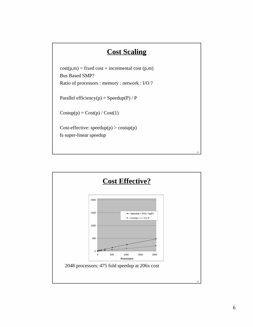
Cost Scaling
cost(p,m) = fixed cost + incremental cost (p,m)
Bus Based SMP?
Ratio of processors : memory : network : I/O ?
Parallel efficiency(p) = Speedup(P) / P
Costup(p) = Cost(p) / Cost(1)
Cost-effective: speedup(p) > costup(p)
Is super-linear speedup
13
Cost Effective?
2048 processors: 475 fold speedup at 206x cost
0
500
1000
1500
2000
0 500 1000 1500 2000
Processors
Speedup = P/(1+ logP)
Costup = 1 + 0.1 P
7
14
Physical Scaling
Chip-level integration
Board-level
System level
15
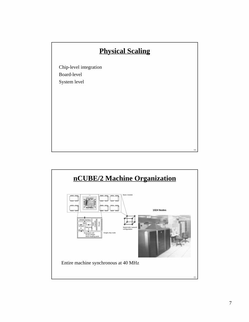
nCUBE/2 Machine Organization
Entire machine synchronous at 40 MHz
Single-chip node
Basic module
Hypercube networkconfiguration
DRAM interface
DM
Ac h
a nn e
ls
Ro u
ter
MMU
I-Fetch&
decode
64-bit integerIEEE floating point
Operand$
Execution unit
1024 Nodes
8
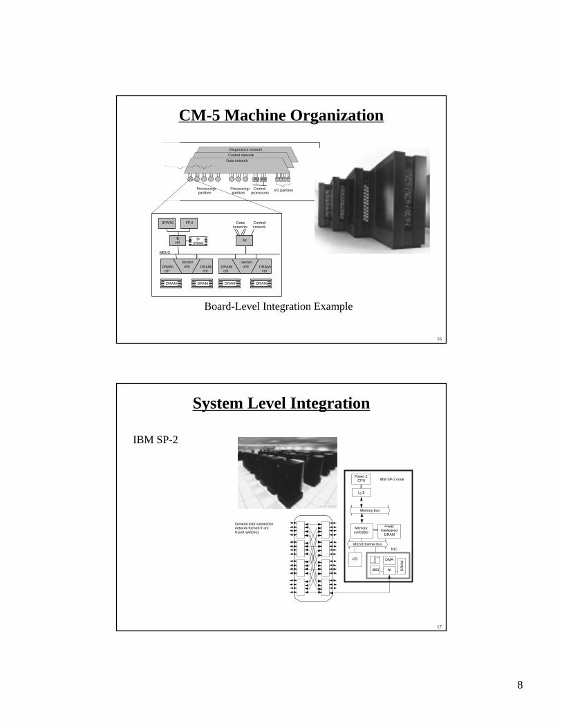
16
CM-5 Machine Organization
Board-Level Integration Example
Diagnostics network
Control network
Data network
Processingıpartition
Processingıpartition
Controlıprocessors
I/O partition
PM PM
SPARC
MBUS
DRAMıctrl
DRAM DRAM DRAM DRAM
DRAMıctrl
Vectorıunit DRAMı
ctrlDRAMı
ctrl
Vectorıunit
FPU Dataınetworks
Controlınetwork
$ıctrl
$ıSRAM
NI
17
System Level Integration
IBM SP-2
Memory bus
MicroChannel bus
I/O
i860 NI
DMA
DR
AM
IBM SP-2 node
L2 $
Power 2CPU
Memorycontroller
4-wayinterleaved
DRAM
General inter connectionnetwork formed fr om8-port switches
NIC
9
20
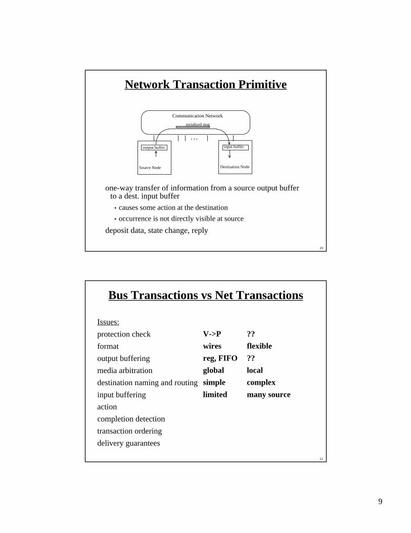
Network Transaction Primitive
one-way transfer of information from a source output bufferto a dest. input buffer
• causes some action at the destination
• occurrence is not directly visible at source
deposit data, state change, reply
output buffer input buffer
Source Node Destination Node
Communication Network
° ° °
serialized msg
21
Bus Transactions vs Net Transactions
Issues:
protection check V->P ??
format wires flexible
output buffering reg, FIFO ??
media arbitration global local
destination naming and routingsimple complex
input buffering limited many source
action
completion detection
transaction ordering
delivery guarantees
10
22
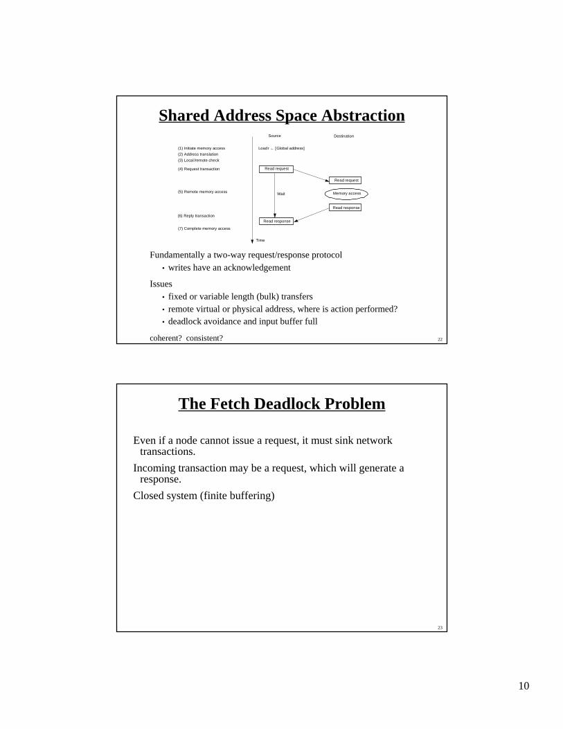
Shared Address Space Abstraction
Fundamentally a two-way request/response protocol• writes have an acknowledgement
Issues• fixed or variable length (bulk) transfers• remote virtual or physical address, where is action performed?• deadlock avoidance and input buffer full
coherent? consistent?
Source Destination
Time
Load r ← [Global address]
Read request
Read request
Memory access
Read response
(1) Initiate memory access
(2) Address translation
(3) Local /remote check
(4) Request transaction
(5) Remote memory access
(6) Reply transaction
(7) Complete memory access
Wait
Read response
23
The Fetch Deadlock Problem
Even if a node cannot issue a request, it must sink networktransactions.
Incoming transaction may be a request, which will generate aresponse.
Closed system (finite buffering)
11
24
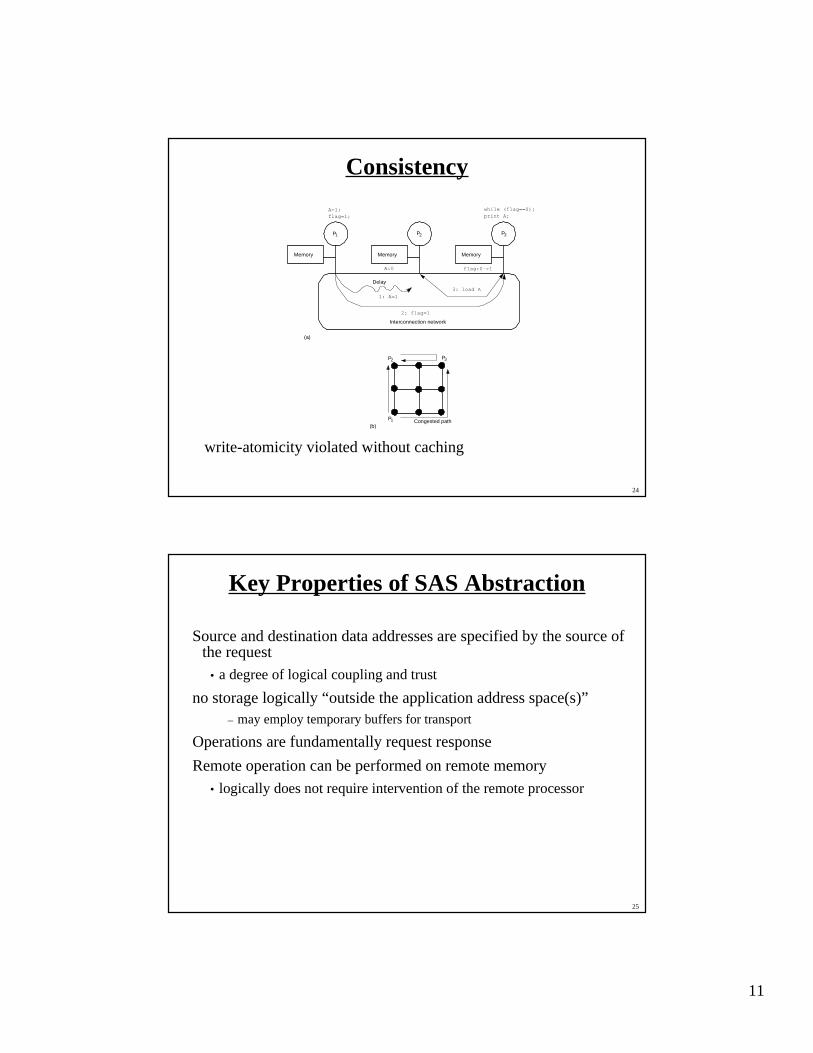
Consistency
write-atomicity violated without caching
Memory
P1 P2 P3
Memory Memory
A=1;flag=1;
while (flag==0);print A;
A:0 flag:0->1
Interconnection network
1: A=1
2: flag=1
3: load A
Delay
P1
P3P2
(b)
(a)
Congested path
25
Key Properties of SAS Abstraction
Source and destination data addresses are specified by the source ofthe request
• a degree of logical coupling and trust
no storage logically “outside the application address space(s)”– may employ temporary buffers for transport
Operations are fundamentally request response
Remote operation can be performed on remote memory
• logically does not require intervention of the remote processor
12
26
Message passing
Bulk transfers
Complex synchronization semantics
• more complex protocols
• More complex action
Synchronous• Send completes after matching recv and source data sent
• Receive completes after data transfer complete from matching send
Asynchronous• Send completes after send buffer may be reused
27
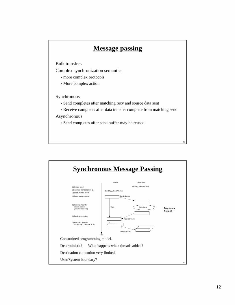
Synchronous Message Passing
Constrained programming model.
Deterministic! What happens when threads added?
Destination contention very limited.
User/System boundary?
Source Destination
Time
Send Pdest, local VA, len
Send-rdy req
Tag check
(1) Initiate send
(2) Address translation on Psrc
(4) Send-ready request
(6) Reply transaction
Wait
Recv Psrc, local VA, len
Recv-rdy reply
Data-xfer req
(5) Remote check for posted receive (assume success)
(7) Bulk data transferSource VA → Dest VA or ID
(3) Local/remote check
Processor Action?
13
28
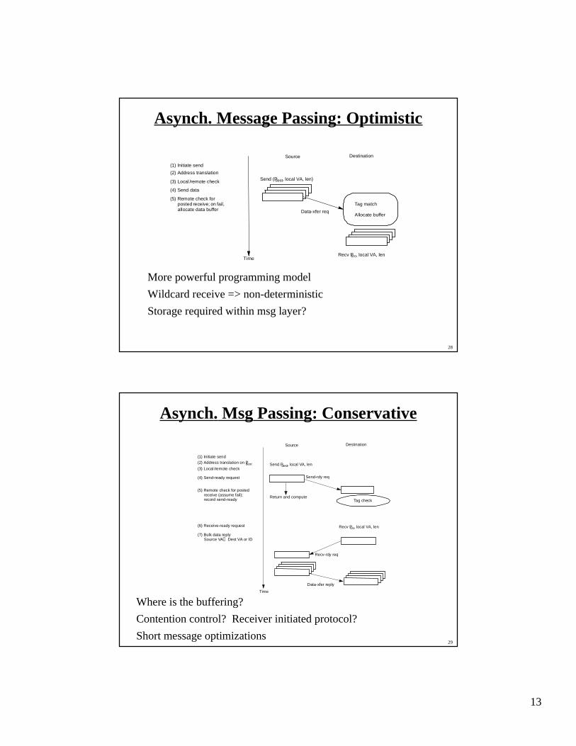
Asynch. Message Passing: Optimistic
More powerful programming model
Wildcard receive => non-deterministic
Storage required within msg layer?
Source Destination
Time
Send (Pdest, local VA, len)
(1) Initiate send
(2) Address translation
(4) Send data
Recv Psrc, local VA, len
Data-xfer req
Tag match
Allocate buffer
(3) Local /remote check
(5) Remote check for posted receive; on fail, allocate data buffer
29
Asynch. Msg Passing: Conservative
Where is the buffering?
Contention control? Receiver initiated protocol?
Short message optimizations
Source Destination
Time
Send Pdest, local VA, len
Send-rdy req
Tag check
(1) Initiate send(2) Address translation on Pdest
(4) Send-ready request
(6) Receive-ready request
Return and compute
Recv Psrc, local VA, len
Recv-rdy req
Data-xfer reply
(3) Local /remote check
(5) Remote check for posted receive (assume fail); record send-ready
(7) Bulk data replySource VA → Dest VA or ID
14
30
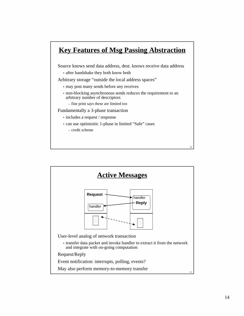
Key Features of Msg Passing Abstraction
Source knows send data address, dest. knows receive data address• after handshake they both know both
Arbitrary storage “outside the local address spaces”
• may post many sends before any receives
• non-blocking asynchronous sends reduces the requirement to anarbitrary number of descriptors
– fine print says these are limited too
Fundamentally a 3-phase transaction
• includes a request / response
• can use optimisitic 1-phase in limited “Safe” cases– credit scheme
31
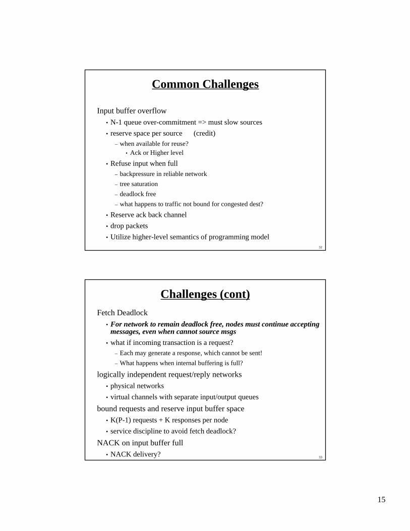
Active Messages
User-level analog of network transaction
• transfer data packet and invoke handler to extract it from the networkand integrate with on-going computation
Request/Reply
Event notification: interrupts, polling, events?
May also perform memory-to-memory transfer
Request
handler
handler
Reply
15
32
Common Challenges
Input buffer overflow
• N-1 queue over-commitment => must slow sources
• reserve space per source (credit)– when available for reuse?
• Ack or Higher level
• Refuse input when full– backpressure in reliable network
– tree saturation
– deadlock free
– what happens to traffic not bound for congested dest?
• Reserve ack back channel
• drop packets
• Utilize higher-level semantics of programming model
33
Challenges (cont)Fetch Deadlock
• For network to remain deadlock free, nodes must continue acceptingmessages, even when cannot source msgs
• what if incoming transaction is a request?– Each may generate a response, which cannot be sent!
– What happens when internal buffering is full?
logically independent request/reply networks• physical networks
• virtual channels with separate input/output queues
bound requests and reserve input buffer space• K(P-1) requests + K responses per node
• service discipline to avoid fetch deadlock?
NACK on input buffer full• NACK delivery?
16
34
Challenges in Realizing Prog. Models inthe Large
One-way transfer of information
No global knowledge, nor global control• barriers, scans, reduce, global-OR give fuzzy global state
Very large number of concurrent transactions
Management of input buffer resources
• many sources can issue a request and over-commit destination beforeany see the effect
Latency is large enough that you are tempted to “take risks”
• optimistic protocols
• large transfers
• dynamic allocation
Many many more degrees of freedom in design and engineering ofthese system
35
Summary
Scalability
• physical, bandwidth, latency and cost
• level of integration
Realizing Programming Models
• network transactions
• protocols
• safety– input buffer problem: N-1
– fetch deadlock
Communication Architecture Design Space
• how much hardware interpretation of the network transaction?
17
36
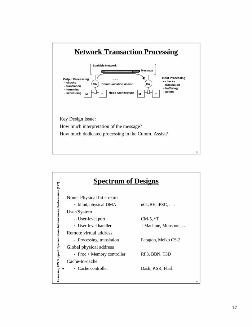
Network Transaction Processing
Key Design Issue:
How much interpretation of the message?
How much dedicated processing in the Comm. Assist?
PM
CA
PM
CA° ° °
Scalable Network
Node Architecture
Communication Assist
Message
Output Processing – checks – translation – formating – scheduling
Input Processing – checks – translation – buffering – action
37
Spectrum of Designs
None: Physical bit stream• blind, physical DMA nCUBE, iPSC, . . .
User/System
• User-level port CM-5, *T
• User-level handler J-Machine, Monsoon, . . .
Remote virtual address
• Processing, translation Paragon, Meiko CS-2
Global physical address• Proc + Memory controller RP3, BBN, T3D
Cache-to-cache
• Cache controller Dash, KSR, Flash
Incr
easi
ng H
W S
uppo
rt, S
peci
aliz
atio
n, In
trus
iven
ess,
Per
form
ance
(??
?)
18
38
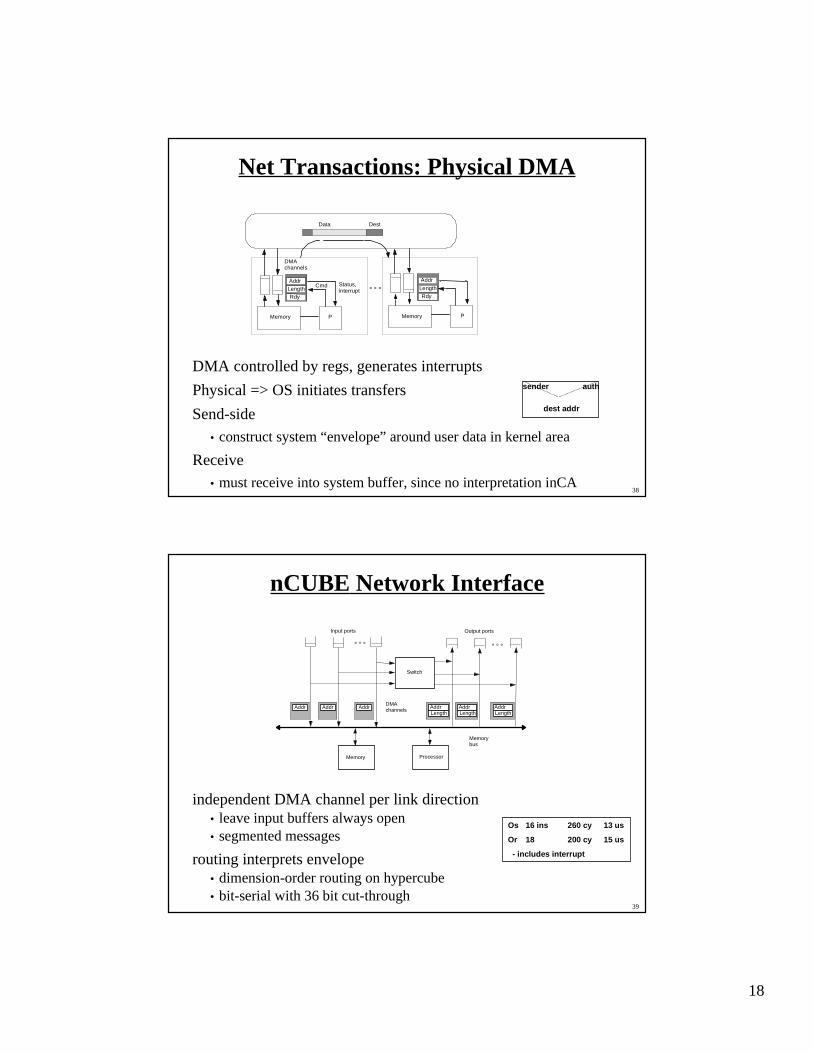
Net Transactions: Physical DMA
DMA controlled by regs, generates interrupts
Physical => OS initiates transfers
Send-side
• construct system “envelope” around user data in kernel area
Receive• must receive into system buffer, since no interpretation inCA
PMemory
Cmd
DestData
AddrLengthRdy
PMemory
DMAchannels
Status,interrupt
Addr
LengthRdy
° ° °
sender auth
dest addr
39
nCUBE Network Interface
independent DMA channel per link direction• leave input buffers always open• segmented messages
routing interprets envelope• dimension-order routing on hypercube• bit-serial with 36 bit cut-through
Processor
Switch
Input ports
° ° °
Output ports
Memory
Addr AddrLength
Addr Addr AddrLength
AddrLength
° ° °
DMAchannels
Memorybus
Os 16 ins 260 cy 13 us
Or 18 200 cy 15 us
- includes interrupt

19
40
Conventional LAN Network Interface
NIC Controller
DMAaddr
len
trncv
TX
RX
Addr LenStatusNext
Addr LenStatusNext
Addr LenStatusNext
Addr LenStatusNext
Addr LenStatusNext
Addr LenStatusNext
Data
Host Memory NIC
IO Busmem bus
Proc
41
User Level Ports
initiate transaction at user level
deliver to user without OS intervention
network port in user space
User/system flag in envelope• protection check, translation, routing, media access in src CA
• user/sys check in dest CA, interrupt on system
PMem
DestData
User/system
PMemStatus,interrupt
° ° °
20
42
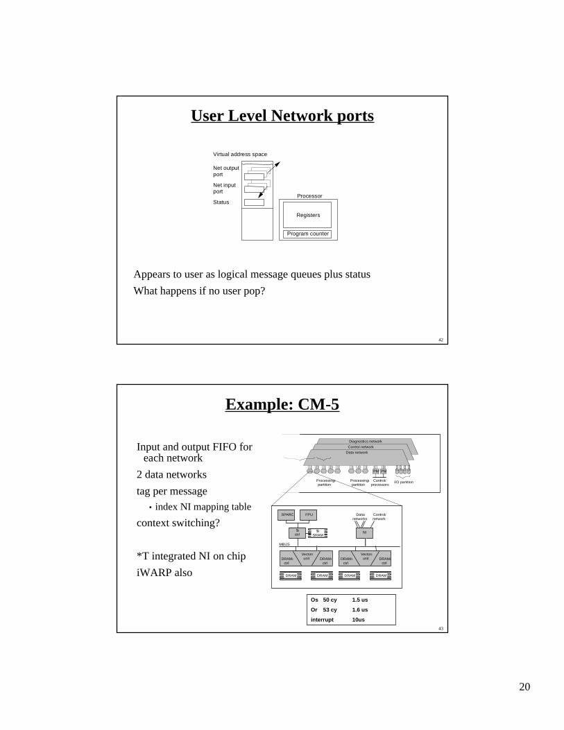
User Level Network ports
Appears to user as logical message queues plus status
What happens if no user pop?
Virtual address space
Status
Net outputport
Net inputport
Program counter
Registers
Processor
43
Example: CM-5
Input and output FIFO foreach network
2 data networks
tag per message• index NI mapping table
context switching?
*T integrated NI on chip
iWARP also
Diagnostics network
Control network
Data network
Processingıpartition
Processingıpartition
Controlıprocessors
I/O partition
PM PM
SPARC
MBUS
DRAMıctrl
DRAM DRAM DRAM DRAM
DRAMıctrl
Vectorıunit DRAMı
ctrlDRAMı
ctrl
Vectorıunit
FPU Dataınetworks
Controlınetwork
$ıctrl
$ıSRAM
NI
Os 50 cy 1.5 us
Or 53 cy 1.6 us
interrupt 10us
21
44
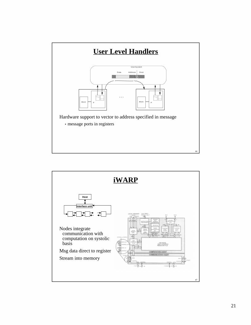
User Level Handlers
Hardware support to vector to address specified in message
• message ports in registers
U se r /sy s te m
PM e m
D e stD ata A d d re ss
PM e m
° ° °
47
iWARP
Nodes integratecommunication withcomputation on systolicbasis
Msg data direct to register
Stream into memory
Interface unit
Host