rockwell ff dvc6000f-1 - fieldbus foundation · – dvc6000 – hart & fieldbus ... air mass...
TRANSCRIPT

FIELDVUE DVC6000f Delivering Digital InnovationFIELDVUE DVC6000f FIELDVUE DVC6000f Delivering Digital InnovationDelivering Digital Innovation
Sanjay K. Soni Sanjay K. Soni –– Fisher Sanmar Ltd.Fisher Sanmar Ltd.
Saurabh Pathak Saurabh Pathak –– Emerson Process Management (AP)Emerson Process Management (AP)
FF End User Event, 18FF End User Event, 18thth Nov 2010 Nov 2010

[File Name or Event]Emerson Confidential27-Jun-01, Slide 2
ContentsContentsContents
� Fisher FIELDVUE Range
� Introduction of DVC6000f
� Operating Principle
� Alerts & Advanced Diagnostics

[File Name or Event]Emerson Confidential27-Jun-01, Slide 3
FIELDVUE InstrumentationFIELDVUE InstrumentationFIELDVUE Instrumentation

[File Name or Event]Emerson Confidential27-Jun-01, Slide 4
FIELDVUE DVC6000f– Exploded ViewFIELDVUE DVC6000fFIELDVUE DVC6000f–– Exploded ViewExploded View
� Built on a proven platform
� Takes FIELDVUE Instruments to a new level
� Easy DVC

[File Name or Event]Emerson Confidential27-Jun-01, Slide 5
DVC6000f - Basic SpecsDVC6000f DVC6000f -- Basic SpecsBasic Specs
� Single or Double Acting
� Foundation Fieldbus Communication
� Common Hardware
– DVC6000 – HART & Fieldbus
– Valve mounted or Remote
� SST Construction Option
� Bus Powered - [polarity insensitive] - 19ma (30% less power)
� -40C to 85C (-52C with optional Fluorosilicone)
� Approvals & Certifications
– Exp. Proof, Div 2 (non-incendive), I.S., flameproof
– FM, CSA, ATEX, IECEx
– NEMA 4X, IEC IP66
– EMC Directive - EN61326-1

[File Name or Event]Emerson Confidential27-Jun-01, Slide 6
� Backup LAS capability
� Increased memory
– Stores Valve Specification Sheet
� Function Blocks Execute Faster– AO Block: 15 ms AI Block: 15 ms
– PID Block: 20 ms MAI Block: 35 ms
– ISEL Block: 20 ms DO Block: 15 ms
– OS Block: 20 ms DI Block: 15 ms
� Faster Control In The Field
– Potential for more and faster loops on segment
� Maximum Current to 19 mA
DVC6000f - Basic SpecsDVC6000f DVC6000f -- Basic SpecsBasic Specs
FOUNDATION™fieldbus
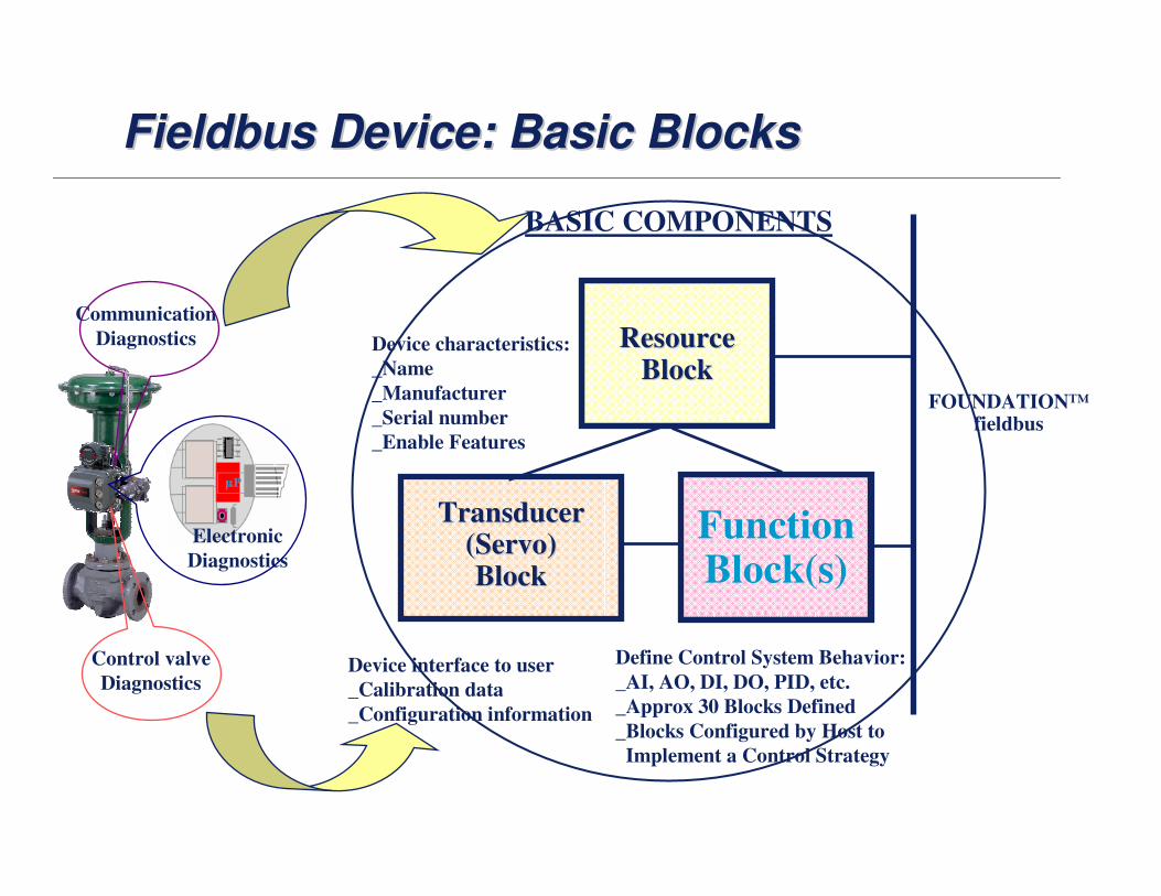
Fieldbus Device: Basic BlocksFieldbus Device: Basic BlocksFieldbus Device: Basic Blocks
BASIC COMPONENTS
FunctionBlock(s)
ResourceResourceBlockBlock
TransducerTransducer(Servo)(Servo)BlockBlock
Device characteristics:
_Name
_Manufacturer
_Serial number
_Enable Features
Device interface to user
_Calibration data
_Configuration information
Define Control System Behavior:
_AI, AO, DI, DO, PID, etc.
_Approx 30 Blocks Defined
_Blocks Configured by Host to
Implement a Control Strategy
Communication
Diagnostics
Electronic
Diagnostics
Control valve
Diagnostics
[File Name or Event]Emerson Confidential27-Jun-01, Slide 8
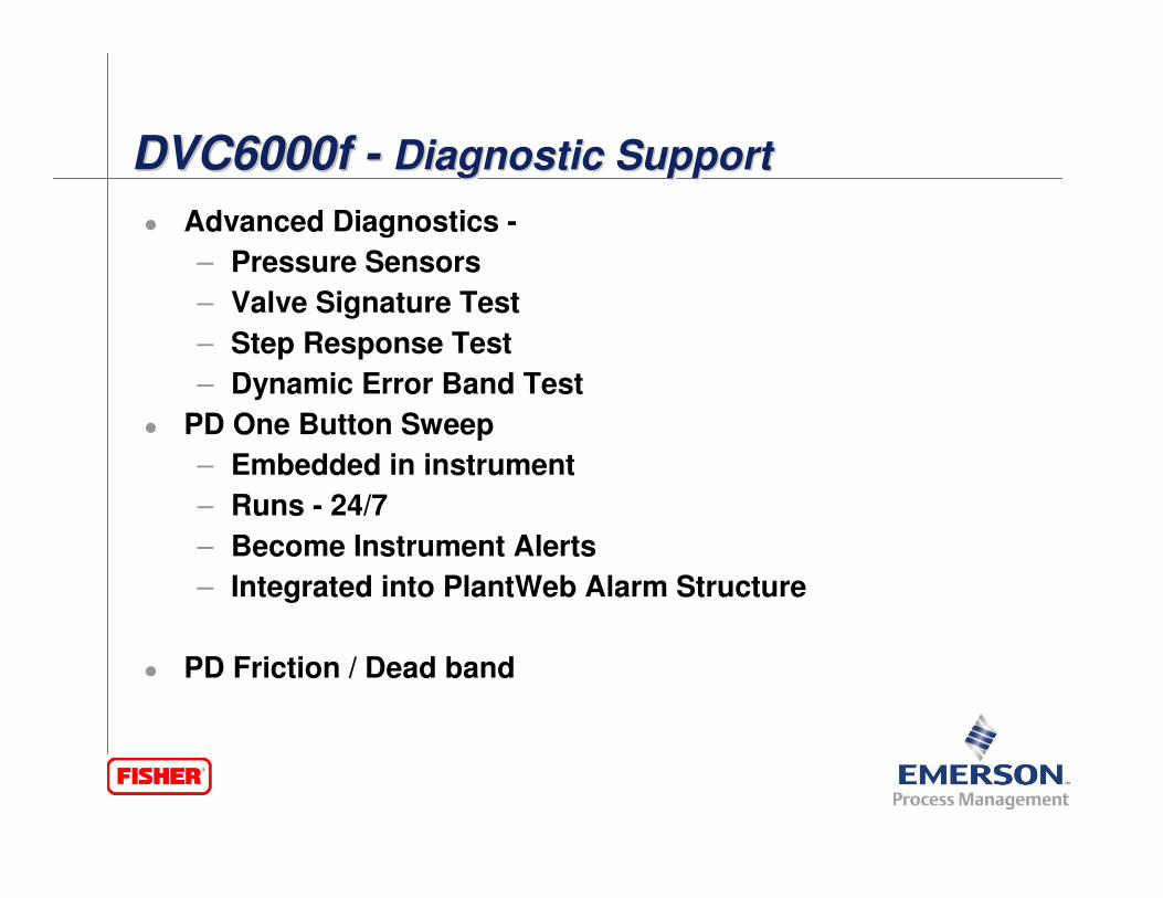
DVC6000f - Diagnostic SupportDVC6000f DVC6000f -- Diagnostic SupportDiagnostic Support
� Advanced Diagnostics -
– Pressure Sensors
– Valve Signature Test
– Step Response Test
– Dynamic Error Band Test
� PD One Button Sweep
– Embedded in instrument
– Runs - 24/7
– Become Instrument Alerts
– Integrated into PlantWeb Alarm Structure
� PD Friction / Dead band

[File Name or Event]Emerson Confidential27-Jun-01, Slide 9
DVC 6000f - Pressure FallbackDVC 6000f DVC 6000f -- Pressure FallbackPressure Fallback
� Three Modes
– Travel Control
– Pressure Control
– Travel Control with Fallback

[File Name or Event]Emerson Confidential27-Jun-01, Slide 10
Software Upgrades - on your schedule ONLINE Software Upgrades Software Upgrades -- on your schedule ONLINE on your schedule ONLINE
� Freedom to upgrade when you want
� Take advantage of firmware enhancements
� Upgrade during process operations

[File Name or Event]Emerson Confidential27-Jun-01, Slide 11
Pneumatic
Relay
I/P
Converter
Terminal
Box
Gauge
Gauge
Gauge
Printed Wiring Board (PWB)
Pressure
Sensors
Output A
Output B
Drive
Signal
I/P
Output
Pressure
Air Supply
Minor Loop
Feedback
Fieldbus Input Signal
Digital Signal
Travel Sensor
Provides Feedback
End Build
Basic Operation…Basic OperationBasic Operation……

[File Name or Event]Emerson Confidential27-Jun-01, Slide 12
Configurable Fisher DVC AlertsConfigurable Fisher DVC AlertsConfigurable Fisher DVC Alerts� Travel Deviation� Travel Hi
� Travel Lo
� Travel Hi Hi
� Travel Lo Lo
� Travel Accumulator
� Drive Signal
� Supply Pressure Alert� Cycle Count
� Valve Stuck high alert
� Ref. Voltage Failure
� Pressure Sensor Fail
� Drive Current Fail
� Temp Sensor Fail
� Travel Sensor Fail
� Output Block Timeout
� Bock Set to Default
� Auto Tvl Cal Failed
� Power Starvation Alert
� Calibration in Progress
� Variable Out of Range
� Diagnostic in Progress
� No Free Time
� Integrator Saturated Low
� Internal Sensor Out of Limits
� Flash Integrity Error
� Integrator Saturated High
� Configuration Changed
� Process Impaired
� Shutdown Alerts
� I/P Plugged alerts
� Relay Jammed
� Valve Stuck Low alert
[File Name or Event]Emerson Confidential27-Jun-01, Slide 13
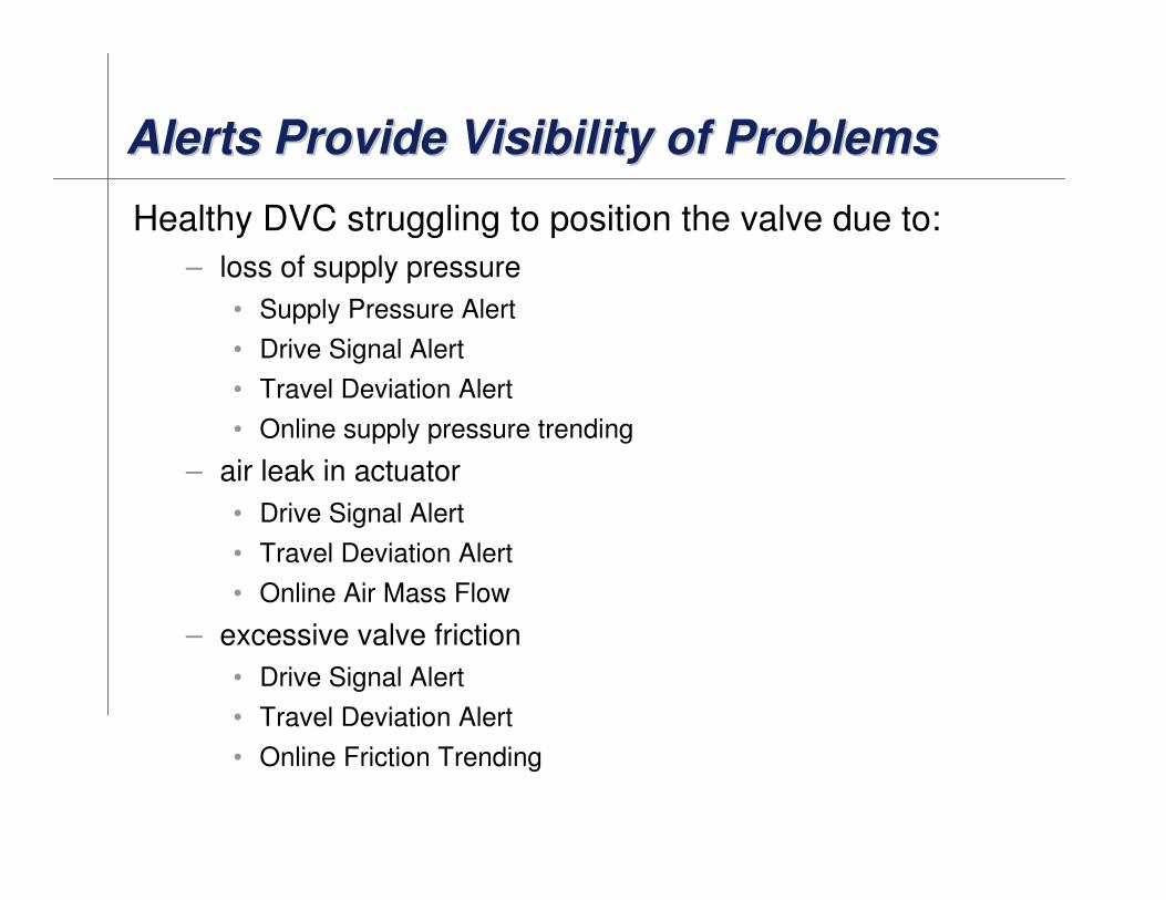
Alerts Provide Visibility of ProblemsAlerts Provide Visibility of ProblemsAlerts Provide Visibility of Problems
Healthy DVC struggling to position the valve due to:
– loss of supply pressure
• Supply Pressure Alert
• Drive Signal Alert
• Travel Deviation Alert
• Online supply pressure trending
– air leak in actuator
• Drive Signal Alert
• Travel Deviation Alert
• Online Air Mass Flow
– excessive valve friction
• Drive Signal Alert
• Travel Deviation Alert
• Online Friction Trending

[File Name or Event]Emerson Confidential27-Jun-01, Slide 14
Alerts Provide Visibility of ProblemsAlerts Provide Visibility of ProblemsAlerts Provide Visibility of Problems
Non-Healthy DVC
– open circuit in the I/P coil
• Drive Current Readback Failure Alert
• Possibly also “Drive Signal” or “Travel Deviation”
– clogged I/P (due to dirty air) or pneumatic relay failure
• intermittent “Drive Signal” Alert
• Travel Deviation
• PD Inside – I/P alert
– travel sensor or linkage incorrect adjustment
• “Travel Sensor Error”
• “Travel Deviation” Alert
• “Travel Hi” or “Travel Lo” Alert

[File Name or Event]Emerson Confidential27-Jun-01, Slide 15
Status Monitor & AlertsStatus Monitor & AlertsStatus Monitor & Alerts

[File Name or Event]Emerson Confidential27-Jun-01, Slide 16
� Performance Diagnostics (PD) is an on-line/in-servicediagnostic tool.
� PD allows remote condition monitoring of a valve without disturbing the process.
• diagnostics and analysis.
– Relay Adjustment, I/P & Relay Integrity, Travel Deviation, Air Mass Flow, Supply Pressure.
• Friction/Deadband measurement and trending.
• Alerts (travel deviation, travel hi/low, supply pressure, internal failures, etc…).
� Automated analysis for predictive maintenance on control valves…information, not just data.
Sustaining Performance with Valve IntelligenceSustaining Performance with Valve IntelligenceSustaining Performance with Valve Intelligence
Y GR / /
[File Name or Event]Emerson Confidential27-Jun-01, Slide 17
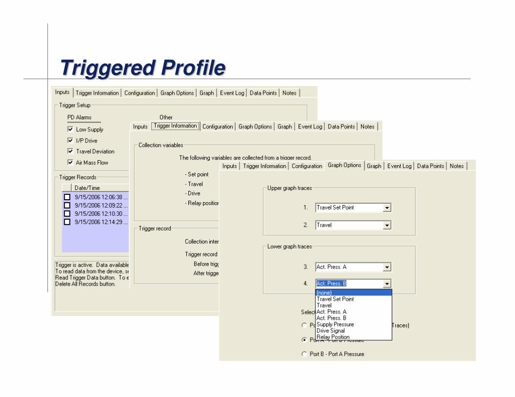
Triggered ProfileTriggered ProfileTriggered Profile
[File Name or Event]Emerson Confidential27-Jun-01, Slide 18
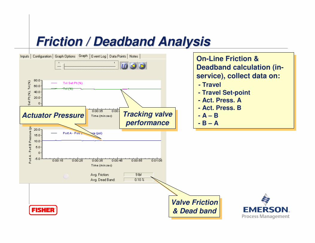
Valve Friction& Dead band
Valve Friction& Dead band
Actuator PressureActuator Pressure Tracking valve
performance
Tracking valve
performance
On-Line Friction &
Deadband calculation (in-service), collect data on:
- Travel
- Travel Set-point
- Act. Press. A
- Act. Press. B
- A – B
- B – A
On-Line Friction &
Deadband calculation (in-service), collect data on:
- Travel
- Travel Set-point
- Act. Press. A
- Act. Press. B
- A – B
- B – A
Friction / Deadband AnalysisFriction / Deadband AnalysisFriction / Deadband Analysis
[File Name or Event]Emerson Confidential27-Jun-01, Slide 19
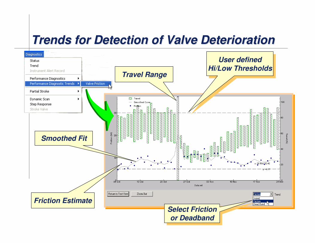
Trends for Detection of Valve DeteriorationTrends for Detection of Valve DeteriorationTrends for Detection of Valve Deterioration
Friction Estimate
Travel Range
Smoothed Fit
Select Frictionor Deadband
Select Frictionor Deadband
User defined
Hi/Low Thresholds
User defined
Hi/Low Thresholds

[File Name or Event]Emerson Confidential27-Jun-01, Slide 20
Types of tests:
– Dynamic Scan: (continuous bidirectional sweep)
• Valve Signature (Actuator Pressure vs Travel)
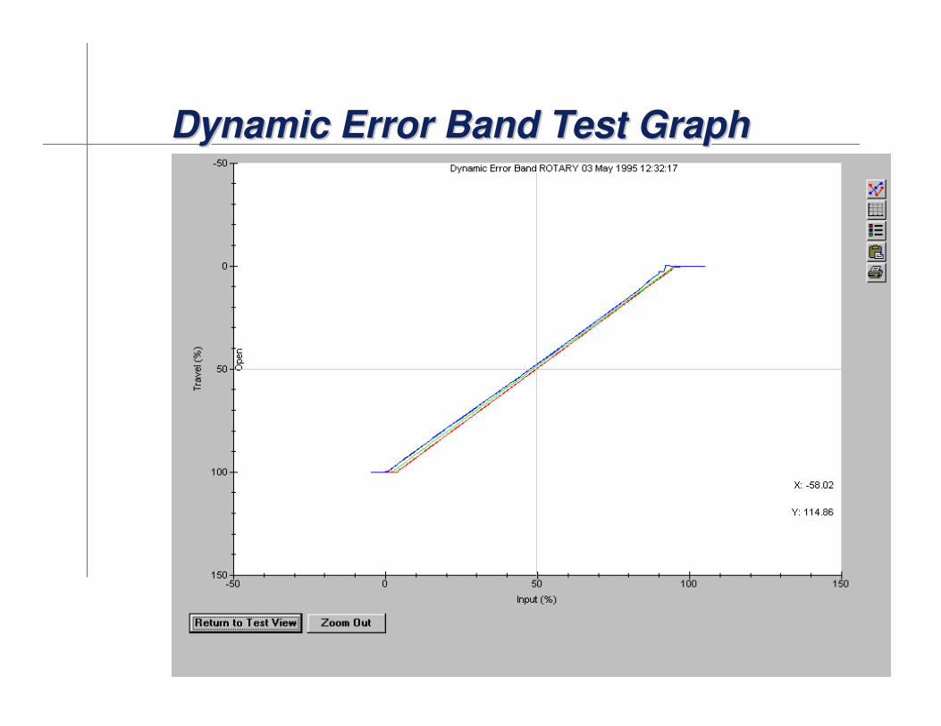
• Dynamic Error Band (Travel vs Input)
• Drive Signal (Drive Signal vs Input)
– Step Response
• Configurable up to 8 steps (End Point, Ramp Time, and Collection Time)
• Performance Step Test (25 predefined profile of ± 0.25%, 0.5%, 1%, 2%,
5%, and 10% steps with 10 second collection time/step)
NOTE: “Input” is really the digitally sequence of Travel Target values commanded to the DVC from the diagnostic test script. The other parameters are measured operational values.
Off-Line Valve DiagnosticsOffOff--Line Valve DiagnosticsLine Valve Diagnostics

[File Name or Event]Emerson Confidential27-Jun-01, Slide 21
Valve Signature BasicsValve Signature BasicsValve Signature Basics
Sliding stem
valve
Quarter turn valve
[File Name or Event]Emerson Confidential27-Jun-01, Slide 22
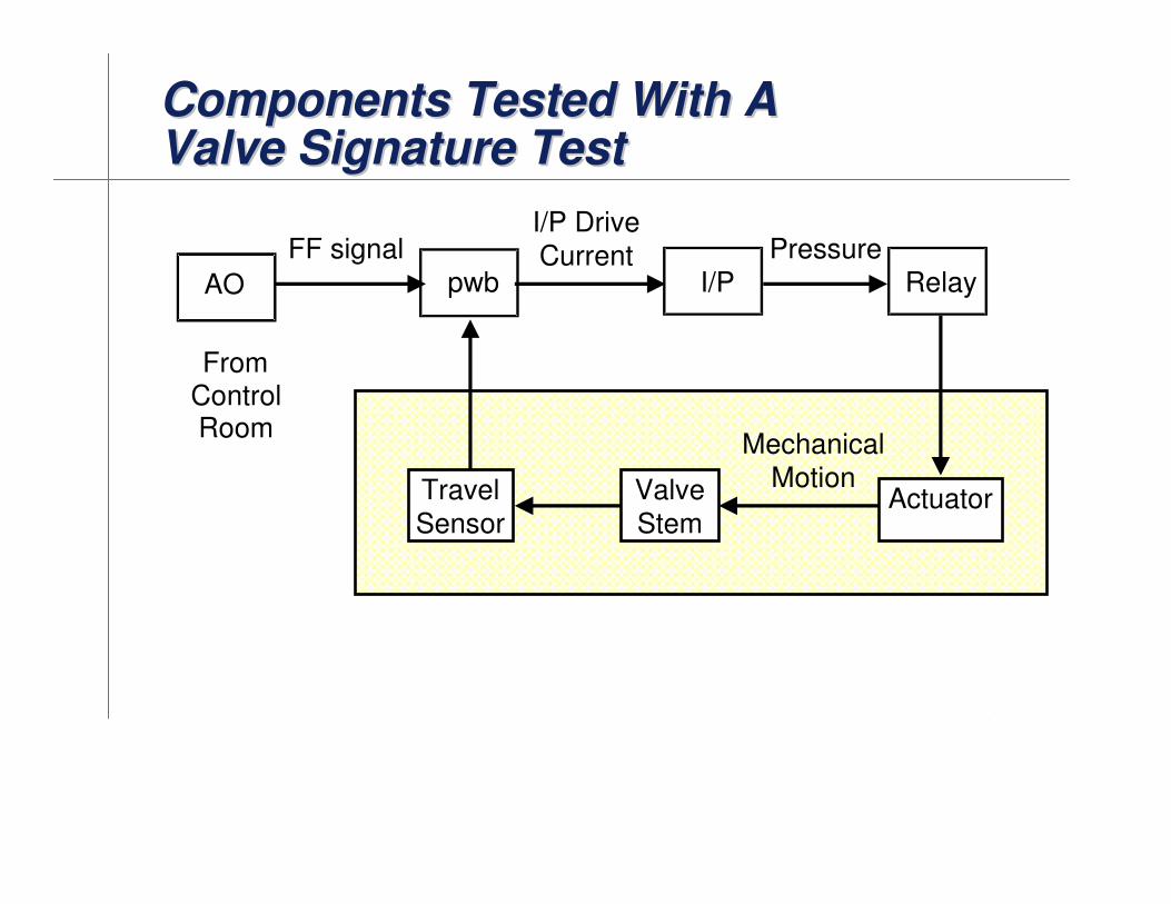
Components Tested With A Valve Signature TestComponents Tested With A Components Tested With A Valve Signature TestValve Signature Test
FF signalI/P DriveCurrent
I/PAO
FromControlRoom
pwbPressure
Relay
MechanicalMotionValve
Stem
Travel
SensorActuator
[File Name or Event]Emerson Confidential27-Jun-01, Slide 23
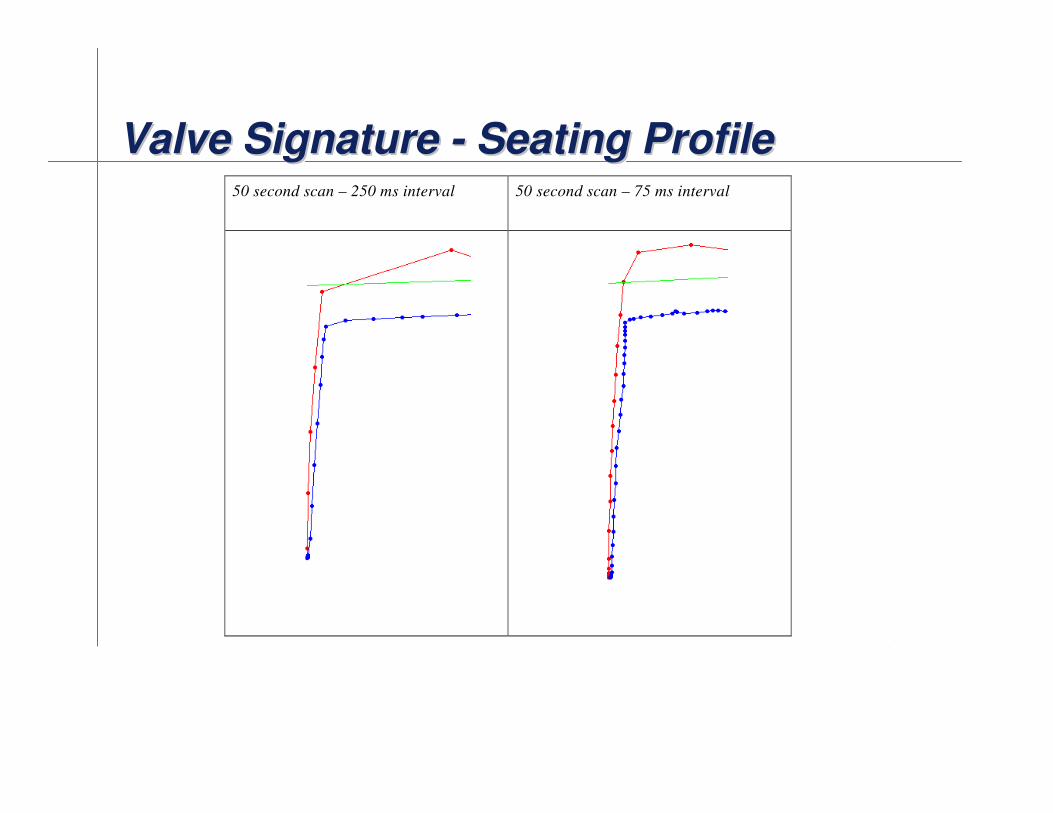
Valve Signature - Seating ProfileValve Signature Valve Signature -- Seating ProfileSeating Profile50 second scan – 250 ms interval 50 second scan – 75 ms interval

[File Name or Event]Emerson Confidential27-Jun-01, Slide 24
Valve Signature - Seating Profile Valve Signature Valve Signature -- Seating Profile Seating Profile

[File Name or Event]Emerson Confidential27-Jun-01, Slide 25
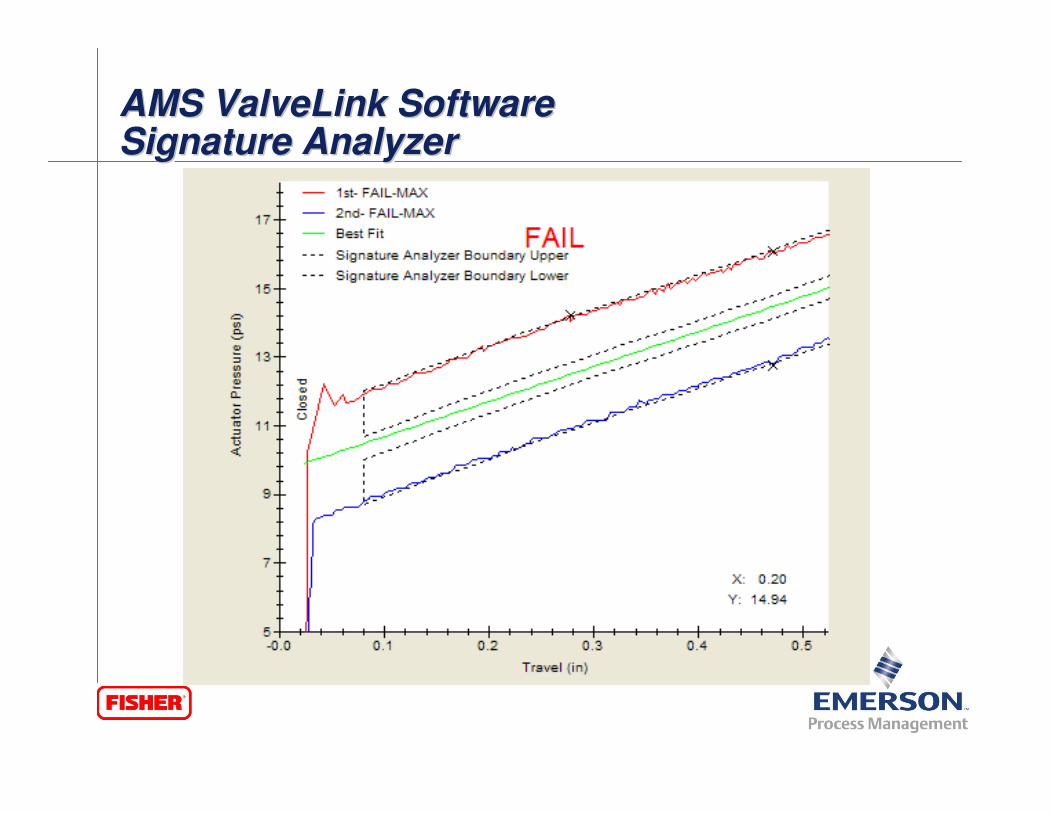
AMS ValveLink SoftwareSignature AnalyzerAMS ValveLink AMS ValveLink SoftwareSoftwareSignature AnalyzerSignature Analyzer
� User configurable travel and friction/torque percent boundaries, and a stick-slip test to determine if there is a problem with the performance of the valve and inform users with an overall PASS/ FAIL result.

[File Name or Event]Emerson Confidential27-Jun-01, Slide 26
AMS ValveLink SoftwareSignature Analyzer – Boundary EditorAMS ValveLink AMS ValveLink SoftwareSoftwareSignature Analyzer Signature Analyzer –– Boundary EditorBoundary Editor
� The Signature Analyzer Boundary Editor is used to modify the boundaries and settings for the Signature Analyzer.
[File Name or Event]Emerson Confidential27-Jun-01, Slide 27
AMS ValveLink SoftwareSignature Analyzer AMS ValveLink AMS ValveLink SoftwareSoftwareSignature Analyzer Signature Analyzer
[File Name or Event]Emerson Confidential27-Jun-01, Slide 28
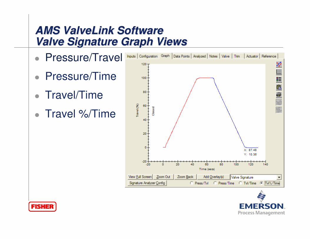
AMS ValveLink SoftwareValve Signature Graph ViewsAMS ValveLink AMS ValveLink SoftwareSoftwareValve Signature Graph ViewsValve Signature Graph Views
� Pressure/Travel
� Pressure/Time
� Travel/Time
� Travel %/Time
[File Name or Event]Emerson Confidential27-Jun-01, Slide 29
Dynamic Error Band Test Graph Dynamic Error Band Test Graph Dynamic Error Band Test Graph
[File Name or Event]Emerson Confidential27-Jun-01, Slide 30
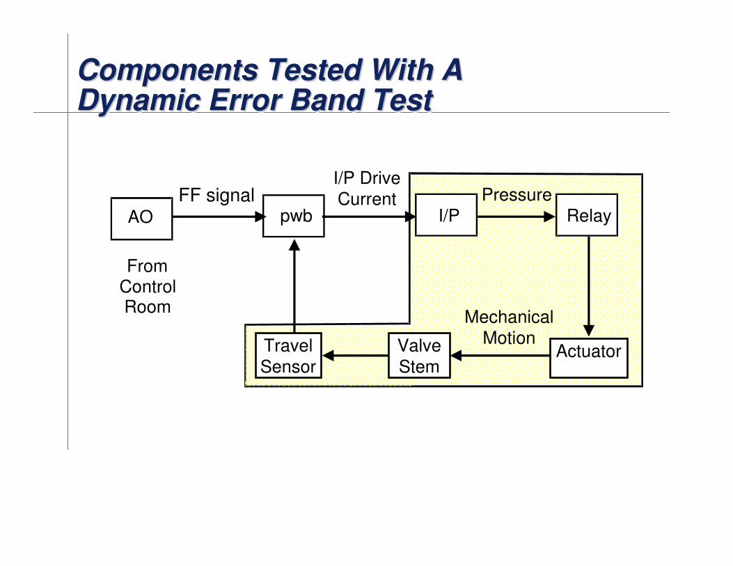
Components Tested With A Dynamic Error Band TestComponents Tested With A Components Tested With A Dynamic Error Band TestDynamic Error Band Test
FF signalI/P DriveCurrent
I/PAO
FromControlRoom
pwbPressure
Relay
MechanicalMotionValve
Stem
Travel
SensorActuator

[File Name or Event]Emerson Confidential27-Jun-01, Slide 31
Drive Signal Test GraphDrive Signal Test GraphDrive Signal Test Graph

[File Name or Event]Emerson Confidential27-Jun-01, Slide 32
Components Tested With A Drive Signal TestComponents Tested With A Components Tested With A Drive Signal TestDrive Signal Test
FF signalI/P DriveCurrent
I/PAO
FromControlRoom
pwbPressure
Relay
MechanicalMotionValve
Stem
Travel
SensorActuator
[File Name or Event]Emerson Confidential27-Jun-01, Slide 33
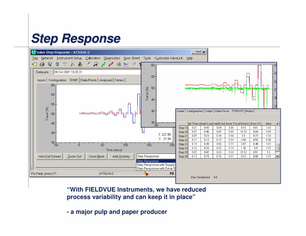
Step ResponseStep ResponseStep Response
“With FIELDVUE Instruments, we have reduced
process variability and can keep it in place”
- a major pulp and paper producer

[File Name or Event]Emerson Confidential27-Jun-01, Slide 34
Components Tested With A Step Response TestComponents Tested With A Components Tested With A Step Response TestStep Response Test
FF signalI/P DriveCurrent
I/PAO
FromControlRoom
pwbPressure
Relay
MechanicalMotionValve
Stem
Travel
SensorActuator
[File Name or Event]Emerson Confidential27-Jun-01, Slide 35
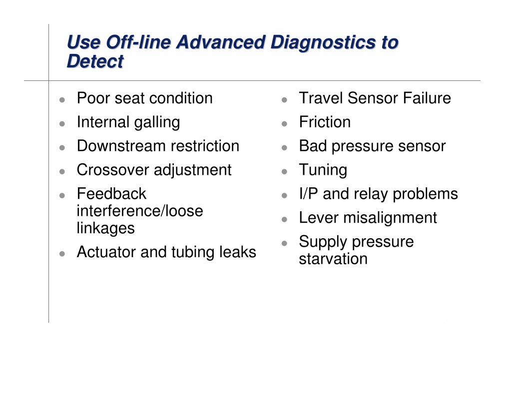
Use Off-line Advanced Diagnostics to DetectUse OffUse Off--line Advanced Diagnostics to line Advanced Diagnostics to DetectDetect
� Poor seat condition
� Internal galling
� Downstream restriction
� Crossover adjustment
� Feedback interference/loose linkages
� Actuator and tubing leaks
� Travel Sensor Failure
� Friction
� Bad pressure sensor
� Tuning
� I/P and relay problems
� Lever misalignment
� Supply pressure starvation

[File Name or Event]Emerson Confidential27-Jun-01, Slide 36
PW-101
FV-101
Diagnostics Methodology (Fieldbus)Diagnostics Methodology (Fieldbus)Diagnostics Methodology (Fieldbus)
Increasing Diagnostic Capability
PlantWeb Alerts
(on-line)
(alert notification)
Performance Diagnostics
(on-line)
(graphs, interpretation)
Dynamic Scan Diagnostics
(off-line)
(graphs, interpretation)
[File Name or Event]Emerson Confidential27-Jun-01, Slide 37
FIELDBUS FIELDVUE Value to you..FIELDBUS FIELDVUE Value to you..FIELDBUS FIELDVUE Value to you..
� Hardware Savings
Accessories such as limit switches and position transmitters can be eliminated because this information is available as function blocks.
� Increased Uptime
The self−diagnostic capability of the DVC6000f digital valve controller provides valve performance and health evaluation without shutting down the process or pulling the valve assembly from the line.
� Improved Maintenance Decisions
Digital communication provides easy access to the condition of the valve. Sound process and asset management decisions can be made by analysis of valve information through Fisher DVC’s and ValveLink software.

Thank you!!Thank you!!Thank you!!