robotics for sustainable broad-acre agriculturerobotics for sustainable broad-acre agriculture*...
TRANSCRIPT

Robotics for Sustainable Broad-Acre Agriculture*
David Ball, Patrick Ross, Andrew English, Tim Patten, Ben Upcroft, Robert Fitch,
Salah Sukkarieh, Gordon Wyeth, Peter Corke
Abstract. This paper describes the development of small low-cost coopera-
tive robots for sustainable broad-acre agriculture to increase broad-acre crop
production and reduce environmental impact. The current focus of the project is
to use robotics to deal with resistant weeds, a critical problem for Australian
farmers. To keep the overall system affordable our robot uses low-cost cameras
and positioning sensors to perform a large scale coverage task while also avoid-
ing obstacles. A multi-robot coordinator assigns parts of a given field to indi-
vidual robots. The paper describes the modification of an electric vehicle for au-
tonomy and experimental results from one real robot and twelve simulated ro-
bots working in coordination for approximately two hours on a 55 hectare field
in Emerald Australia. Over this time the real robot ‘sprayed’ 6 hectares missing
2.6% and overlapping 9.7% within its assigned field partition, and successfully
avoided three obstacles.
1 Introduction
The current trend in agriculture is to increase the farmer’s productivity by using larger
machinery combined with controlled traffic farming, which is where the vehicles
traverse exactly the same paths using precision guidance. However, the growth in
complexity, size and weight of agricultural equipment, combined with repeatedly
traversing the same path, has led to concentrated soil compaction damage as well as
longer disruptions due to single machine failures. Soil compaction and single points
of failure ultimately decrease yield and productivity. The goal of this project is to
create a new class of machines for sustainable agriculture that will increase broad-
acre crop production and reduce environmental impact; small, light, inexpensive ro-
bots that coordinate as a team to manage the fields and work 24 hours a day. This
represents a movement back towards a time when large numbers of human workers
would tend the fields and provide individualised plant treatment.
This project is focussed on an immediate problem facing farms in Australia – re-
sistant weeds. Zero-tillage agriculture, where soil disturbance is kept to a minimum, is
considered best practice farming in Australia to reduce topsoil erosion. However, to
* DB, PR, AE, BU, GW, PC are with the School of Electrical Engineering and Computer
Science at the Queensland University of Technology (QUT). TP, RF, SS are with the Aus-
tralian Centre for Field Robotics at The University of Sydney. Correspondence should be
addressed to [email protected]. This work was supported in part by the Australian Re-
search Council Linkage Project LP110200375 “Robotics for Zero-Tillage Agriculture”
awarded to QUT, SwarmFarm Robotics and The University of Sydney.
compensate for removing a mechanical means of weed destruction, farmers typically
use more herbicide to manage weeds which has led to the emergence of resistant
weeds. The magnitude of the issue in Australia is that the agricultural cost of weeds
alone is in the vicinity of $4 billion per annum [1]. Our solution to combat increasing
weed resistance is to introduce multiple lighter machines that are able to be deployed
into the field rapidly after a rain event as they are less prone to being bogged, cause
less soil damage, and operate as a system that is more robust to individual machine
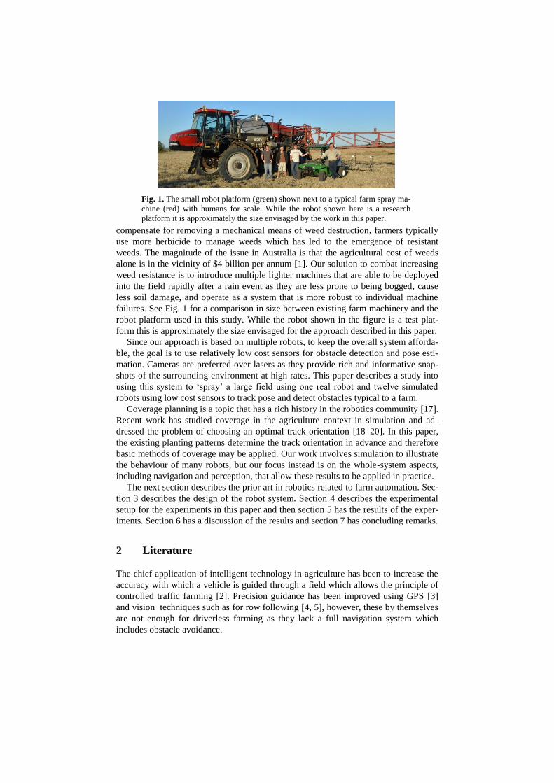
failures. See Fig. 1 for a comparison in size between existing farm machinery and the
robot platform used in this study. While the robot shown in the figure is a test plat-
form this is approximately the size envisaged for the approach described in this paper.
Since our approach is based on multiple robots, to keep the overall system afforda-
ble, the goal is to use relatively low cost sensors for obstacle detection and pose esti-
mation. Cameras are preferred over lasers as they provide rich and informative snap-
shots of the surrounding environment at high rates. This paper describes a study into
using this system to ‘spray’ a large field using one real robot and twelve simulated
robots using low cost sensors to track pose and detect obstacles typical to a farm.
Coverage planning is a topic that has a rich history in the robotics community [17].
Recent work has studied coverage in the agriculture context in simulation and ad-
dressed the problem of choosing an optimal track orientation [18–20]. In this paper,
the existing planting patterns determine the track orientation in advance and therefore
basic methods of coverage may be applied. Our work involves simulation to illustrate
the behaviour of many robots, but our focus instead is on the whole-system aspects,
including navigation and perception, that allow these results to be applied in practice.
The next section describes the prior art in robotics related to farm automation. Sec-
tion 3 describes the design of the robot system. Section 4 describes the experimental
setup for the experiments in this paper and then section 5 has the results of the exper-
iments. Section 6 has a discussion of the results and section 7 has concluding remarks.
2 Literature
The chief application of intelligent technology in agriculture has been to increase the
accuracy with which a vehicle is guided through a field which allows the principle of
controlled traffic farming [2]. Precision guidance has been improved using GPS [3]
and vision techniques such as for row following [4, 5], however, these by themselves
are not enough for driverless farming as they lack a full navigation system which
includes obstacle avoidance.
Fig. 1. The small robot platform (green) shown next to a typical farm spray ma-
chine (red) with humans for scale. While the robot shown here is a research
platform it is approximately the size envisaged by the work in this paper.

Early work in developing autonomous farm machinery is described by Ollis and
Stentz [6] who use vision for following the boundary between cut and uncut crop and
demonstrated harvesting over 48 hectares of crop [7]. To detect obstacles they use
probability density functions to threshold novel regions in the images demonstrating
preliminary results. Stentz et al. [8] describes a semi-autonomous tractor, which waits
for human advice when detecting an obstacle in the path of the robot. A human trains
the system by driving the relevant routes and the robot uses pure pursuit [9] to follow
the path. To detect obstacles they combine a neural network processing single images
with a stereo camera system. Torii et al. [10] reviews a number of approaches includ-
ing using neural networks, genetic algorithms, and fuzzy logic for robots capable of
tillage, planting and plant care.
Since then there have been numerous approaches to the robotics farm with a signif-
icant focus on adding a variety of sensors to existing tractors. Johnson et al. [11] de-
scribe a complete multi-robot system demonstrated working over a long period of
time. To detect obstacles the tractor has colour cameras, infrared cameras and a nod-
ding laser which generates tagged 3D data. Recent long term work in an orchard, with
a similar set of sensors added to an existing tractor, demonstrates substantial produc-
tivity improvements of 30% over human operated machinery [12].
Some groups have focussed on the development of custom platforms. Bakker et al.
[13] describe a systematic approach to the design of an autonomous platform for robot
weeding considering a large range of issues such as: methods to detect the weeds and
destroy them, guidance technique, energy sources and vehicle type. The result of their
design process is a four wheel driven and steered mechanical weeder guided by vision
and GPS. Another example is the BoniRob [14] which can vary its height and track
width to suit different fields and was designed for sensing the state of the crop. Horti-
bot [15] and Armadillo [16] are designed as custom generic flexible tool carriers.
3 System Design
The overall system, shown in Fig. 2, consists of a centralised multi-robot planner that
takes regions for spray coverage and assigns each robot a section to cover. The multi-
robot planner sends each robot the perimeter and a list of waypoints that define each
pass. The robots regularly send back their global locations. The system is designed to
allow each robot to operate autonomously within its assigned section of the field,
independent of the multi-robot planning system, for extended periods of time. The
system uses a 3G mobile data connection to communicate over the internet between
the multi-robot planner and the robots. Mobile data may dropout, in particular in rural
areas, however the system is designed to gracefully handle long and regular periods of
communication drop out. The following sections describe the robot system including
its sensors, and then describe each of the main software components.

3.1 Robot platform
The agricultural robot platform is based on a John Deere TE Gator modified for au-
tonomous operation. The Gator is an Ackermann steered 48V 4.6kW electric vehicle,
approximately 2.6 meters long and 1.5 meters wide, with a ground clearance of 0.18
meters. The vehicle has a nominal 8 hour battery life and 12 hour recharge time. The
Gator is fitted with an automation conversion kit supplied by RoPro Design. The
computer controls the vehicle over a Controller Area Network (CAN) bus by inter-
cepting the control lines that feed into the Gator’s standard motor controller and add-
ing a smart motor to control the steering wheel and another smart motor to control the
brake. Via a single switch the vehicle can be changed between autonomous and man-
ual human driven modes. For emergencies, a pneumatic emergency brake has also
been fitted to the robot and can be released via local estop buttons or wirelessly. The
robot has been fitted with a 200L spray tank, 5 meter wide boom with spray nozzles
and a commercial plant detection system, WeedIT. The robot receives Real Time
Kinematic (RTK) precision correction data from the SmartNet Australian Continually
Operating Reference Station (CORS) network. The robot has several sensors.
Two forward facing iDS UI-5240CP Power over Ethernet GigE cameras
with wide field of view lens (~US$1,400 each).
Two quadrature encoders S63B-37ADQ-OCCP4-AF mounted on the rear
wheels providing a resolution of 6mm (~US$250 each).
A CH Robotics UM6 Inertia Measurement Unit (IMU) (~US$200).
A Skytraq S1315F-RAW GNSS with Tallysman TW3100 (~US$300).
Fig. 2. System architecture. The farmer interacts with the multi-robot coor-
dination module which then communicates with the rest of the system over
a 3G mobile data connection via the internet.

Fig. 3. The agricultural research platform, used to test the sensors and algorithms,
shown on a sorghum stubble field. The base vehicle is an electric John Deere TE Ga-
tor. The strobe light was used for night time studies not described in this paper.
3.2 Software and Hardware details
The robot runs the Robot Operating System (ROS) [21] framework which uses a top-
ic-based publish and subscribe model. Local and remote nodes communication over
topics using pre-defined messages. The robot has two standard off the shelf computers
running Ubuntu 12.04 and ROS Fuerte, one that runs the traversability node and the
other for localisation, path planning and vehicle control. The traversability node sends
information about obstacles using a ROS PointCloud message. The path planner
communicates the desired motion using ROS ackermann_msgs. The path planners use
the ROS move_base and costmap framework. Most of the nodes on the robot operate
at 10 Hz.
A separate laptop is used to run the multi-robot planner and communicates with the
rest of the system over 3G. Potential problems with 3G include narrow bandwidth,
delays and network failures; however, this isn’t a problem as the communication be-
tween the multi-robot planner and the robots is limited to sparse commands and status
updates. To handle communication failures and provide namespace separation, there
are two ROS masters, one is on a laptop computer, and another is on the robot. These
communicate using custom messages over a ROS actionlib interface and relevant
topics are connected using ROS foreign_relays.
3.3 Multi-Robot Planner
The task of weed management through controlled herbicide delivery is algorithmical-
ly an instance of the coverage problem [22]. This section describes the planning sub-
system for multi-robot coverage of large fields.
The goal of coverage is to plan a path such that the robot(s) eventually visit (cover)
all points within a defined area. Finding an optimal coverage path is related to the
well-known Travelling Salesman Problem (TSP) and is NP-hard [23]. However, this
application is a restricted case of coverage where robot motion is constrained to travel
parallel to pre-existing rows within a field. In this case, cell-decomposition algorithms
work well in practice.
Following [22], we apply the boustrophedon decomposition, where the coverage
area is exactly partitioned according to a back-and-forth (lawnmower) pattern. For a
single field with crop rows at a known row orientation, the boustrophedon decomposi-
tion is computed using a sweep-line moving perpendicular to the rows. This method
partitions the paddock into cells of approximately-equal area measured by the sum of
row lengths. One robot is allocated to each cell. The robot's path within its cell is
determined by the existing row pattern which can be obtained from satellite data or
from the farmer. The number of cells within a field is determined by the number of
available robots. The initial decomposition and allocation of cells to robots is comput-
ed offline given the field boundaries. For this, the system calculates a list of way-
points located at the start and end of each pass. Then, each robot performs row-
following and obstacle avoidance within its allocated cell using the algorithms de-
scribed in the following sections. Cells may also be allocated to simulated robots that
operate simultaneously with real robots, although the simulated robots drive directly
to waypoints without obstacle avoidance.
3.4 Coverage planner
This node, which runs on each robot, is responsible for ensuring the robot follows the
coverage plan waypoints provided by the multi-robot planner. It sequentially provides
the next goal waypoint located at the end of each row. The node also sends a funnel
field to the costmap to ensure that even while avoiding obstacles the robot will stay
close to the row. The funnel field strength is proportional to the distance from the
desired path and so forms an inverted triangle. So that overall progress can be tracked,
this node regularly sends the multi-robot planner the global location of the robot.
3.5 Pose Estimation
For localization, a particle filter combines sensor information from several low-cost
sensors, specifically a single-channel GPS, IMU and velocity from the robot’s wheel
encoders. The particle filter allows the robot to determine its pose based on a series of
noisy readings and allows the robot to continue to operate even if GPS drops out for a
period of time. GPS position calculations are performed on the robot’s PC using the
free software library RTKLIB [24] which applies RTK corrections to the raw GPS
satellite observations to dramatically improve the robot’s global accuracy. The robot
receives corrections from the CORS network via a 3G internet connection.
3.6 Traversability
This node is responsible for determining the traversability of the area in front of the
robot using only vision. Currently, the node detects obstacles, which is a subset of
traversability which would include determining the terrain type.
The node firstly determines novel regions in the left camera image and then pro-
cesses these novel regions using stereo vision. To determine novel regions the node
maintains a model of the typical appearance of the field, under the assumption that
obstacles typically deviate significantly from this appearance model. Candidate obsta-
cles are detected in image space by looking for novel image regions with respect to
this model. Novelty detection uses a weighted variant of Parzen windows [25] where
samples lose weighting over time. Fast inference on this model is performed using the
Fast Library for Approximate Nearest Neighbours (FLANN). Candidate obstacle
image regions are then passed through stereo matching in order to generate a metric
point cloud of the candidate obstacles. Stereo matching was performed using
LIBELAS [26]. The point cloud is filtered based on their height and distance from the
camera, and the remaining points are obstacles.
This two-step process has advantages over purely stereo matching-based obstacle
detection. The first advantage is that stereo matching typically performs poorly in
agricultural fields due to its highly repetitive nature, hence stereo matching alone
generates significant false positives. Empirical results indicated that stereo matching
is more robust on obstacles over stubble (based on the assumption that their appear-
ance deviates from the typical), since obstacles provide strong edges which are useful
for stereo matching. The novelty pre-processing then implicitly encodes an under-
standing of the image regions in which stereo matching performs well, and signifi-
cantly reduces false positives while having negligible impact in terms of false nega-
tives. The second advantage is that since stereo matching is only performed on a sub-
set of the image regions, it typically has a reduced computational load for equivalent
performance.
3.7 Costmap
The costmap maintains a 2D representation of the environment surrounding the robot
and the global lattice planner and local pure pursuit planner use it to generate paths.
As is typical, the map encodes the cost of the robot occupying particular cells. To
ensure that obstacles are avoided and the robot remains on the desired row, the obsta-
cles are given high values and the funnel from the coverage planner is given low to
medium values. Specifically, each cell is 0.2 meters squared and the costmap is 100
meters squared centered on the robot. The costmap is aligned with the known direc-
tion of the crop rows to allow the system to plan smooth straight paths.
3.8 Global lattice planner
This node plans a long-term path to the coverage planner’s goal pose through the
costmap. This node uses the Search Based Lattice Planner (SBPL) [27] to generate

collision free paths around obstacles. SBPL incrementally searches for the best path
considering the cost of motion primitives and the cost of traversing the costmap cell.
Obstacles have high cells costs. The funnel provided by the robot’s coverage node,
provides increasing costs perpendicular to the desired row, and therefore ensures that
SBPL will generate paths that, after avoiding an obstacle, will guide the robot back
onto the correct row. SBPL constructs the path using motion primitives specific to the
Gator vehicle. These motion primitives represent the Gator vehicle’s kinematics, in
particular the minimum radius of curvature, and include travelling straight and turning
left and right. These plans extend in the direction of the goal and are clipped to the
extent of the costmap.
For typical row following without obstacles this approach is more complex than
required however provides flexibility for the future functionality such as moving be-
tween fields. The global lattice planner recalculates a new path every 10 seconds, or
when the goal changes or when the local planner rejects the plan.
3.9 Local pure pursuit controller
This node is responsible for ensuring that the robot tracks the long-term lattice path
using a pure pursuit controller [9]. The node has two proportional integral controllers
to minimize the error in the distance between the robot and the lattice path and be-
tween the robot’s heading and the lattice path orientation. The pure pursuit controller
plans the path of the robot forward several seconds checking for collisions between
the robot footprint and obstacles in the costmap. If a collision is detected then the
local controller rejects the global path and the robot slows down while the global
lattice planner generates a new path. In practice, as the global lattice planner quickly
generates paths, the robot does not slow down notably.
3.10 Vehicle Controller
The vehicle controller node manages the low-level state of vehicle including the for-
ward velocity of the robot, the steering wheel angle and the state of the brake. The
controller interfaces with the vehicle over a CAN bus to smart motors and relays. The
node has a hand-tuned proportional-integral-feedforward velocity controller based on
feedback of the robot’s velocity from the wheel encoders.
4 Experimental Setup
The user defines the boundary of the field by manually selecting appropriate latitude
and longitude coordinates as shown in Fig. 4. The area represented by the coordinates
in this experiment are slightly smaller than the actual field to avoid the headland
which is where the large farm machinery turns around at the end of each row. The
area defined for this experiment is 55 hectares of broad-acre sorghum stubble field
located in Emerald, Australia. In the section of the field assigned by the multi-robot
planner to the real robot there are three obstacles typically found on a farm and in-
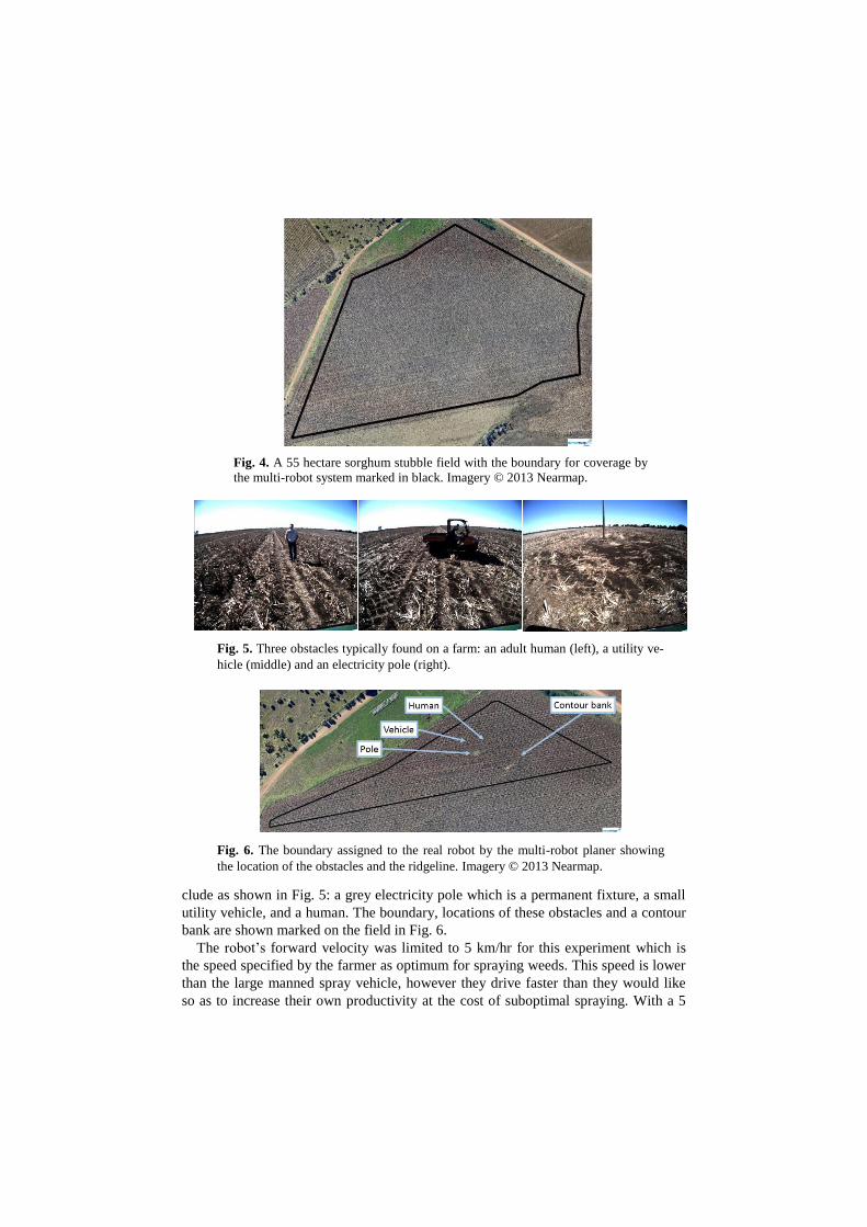
clude as shown in Fig. 5: a grey electricity pole which is a permanent fixture, a small
utility vehicle, and a human. The boundary, locations of these obstacles and a contour
bank are shown marked on the field in Fig. 6.
The robot’s forward velocity was limited to 5 km/hr for this experiment which is
the speed specified by the farmer as optimum for spraying weeds. This speed is lower
than the large manned spray vehicle, however they drive faster than they would like
so as to increase their own productivity at the cost of suboptimal spraying. With a 5
Fig. 4. A 55 hectare sorghum stubble field with the boundary for coverage by
the multi-robot system marked in black. Imagery © 2013 Nearmap.
Fig. 5. Three obstacles typically found on a farm: an adult human (left), a utility ve-
hicle (middle) and an electricity pole (right).
Fig. 6. The boundary assigned to the real robot by the multi-robot planer showing
the location of the obstacles and the ridgeline. Imagery © 2013 Nearmap.

meter wide spray boom travelling at 5 km/hr it would take one robot approximately
26 hours to traverse this 55 hectare field. For this experiment the multi-robot planner
was configured to use 1 real and 12 simulated robots.
The goal is to cover the entire field only once while minimizing the missing and
overlapped areas. Therefore, the pass-to-pass error is calculated based on the perpen-
dicular distance to the previous vehicle pass, ignoring the turning regions at the ends
of the rows and avoiding obstacles. The user configured the multi-robot planner with
a pass-to-pass distance of 5 meters to generate the waypoints for the robots. The cov-
erage results are based on a 5.5 meter wide boom due to the side spray from the noz-
zles on the ends of the boom. A high-performance Novatel multi-constellation GNSS
with tactical grade IMU and dual antennas provides ground truth data, and its posi-
tions are used for calculating coverage results and for plotting the paths.
5 Results
Fig. 7 illustrates the performance of the path planning nodes in avoiding one of the
obstacles detected using only vision. The costmap shows the obstacles added at the
correct location. Some detection of obstacles is made at 10 meters away while robust
detection occurs at 5 metres. The combination of the funnel and the obstacle means
that the global lattice planner determines a path that avoids the obstacle and guides
the robot back onto the original row path. The obstacle detection and path planning
results are similar for the other two obstacles.
Fig. 7. Demonstration of the robot avoiding a human during the coverage task.
The camera image showing the position of the human and highlighted regions
of the image that the traversability node has detected as novel (left). The cost-
map and path planner outputs are shown on the (right). The dark blue shows the
output from the traversability node showing that the human is added as an ob-
stacle and that the stubble detected as novel is not added as an obstacle. The
funnel gradient, in greyscale, can be clearly seen biasing the robot’s path back
onto the row. The green outline represents the robot’s footprint. The red line is
the global lattice path and the small cyan line is the pure pursuit plan.
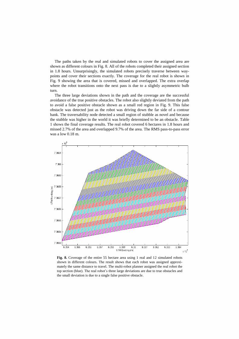
The paths taken by the real and simulated robots to cover the assigned area are
shown as different colours in Fig. 8. All of the robots completed their assigned section
in 1.8 hours. Unsurprisingly, the simulated robots precisely traverse between way-
points and cover their sections exactly. The coverage for the real robot is shown in
Fig. 9 showing the area that is covered, missed and overlapped. The extra overlap
where the robot transitions onto the next pass is due to a slightly asymmetric bulb
turn.
The three large deviations shown in the path and the coverage are the successful
avoidance of the true positive obstacles. The robot also slightly deviated from the path
to avoid a false positive obstacle shown as a small red region in Fig. 9. This false
obstacle was detected just as the robot was driving down the far side of a contour
bank. The traversability node detected a small region of stubble as novel and because
the stubble was higher in the world it was briefly determined to be an obstacle. Table
1 shows the final coverage results. The real robot covered 6 hectares in 1.8 hours and
missed 2.7% of the area and overlapped 9.7% of the area. The RMS pass-to-pass error
was a low 0.18 m.
Fig. 8. Coverage of the entire 55 hectare area using 1 real and 12 simulated robots
shown in different colours. The result shows that each robot was assigned approxi-
mately the same distance to travel. The multi-robot planner assigned the real robot the
top section (blue). The real robot’s three large deviations are due to true obstacles and
the small deviation is due to a single false positive obstacle.

Fig. 9. This plot shows the coverage for the real robot (grey) within its assigned
boundary (red) including the parts of the field where the spray would be over-
lapped (black) and missed part of the field (white). The top three large missed
and overlapped areas are true positive obstacles that were successfully avoided.
The small area towards the bottom in the middle was where the robot slightly
deviated to avoid a false positive obstacle.
Table 1. These results represent the overall performance of the real robot for
the coverage task.
Result Metric
Missed percentage 2.6%
Overlap percentage 9.7%
True positive obstacles avoided 3
False positive obstacles avoided 1
Real robot run time 1.8 hours
Area covered 6 hectares
RMS pass-to-pass error 0.18 meters
6 Discussion
The robot autonomously ‘sprayed’ 97.4% of its section of the field while avoiding
obstacles typical to the farm environment. The real robot was shown to work along-
side many simulated robots to perform complete coverage of a large area. The robot
was able to globally localise to perform the coverage task with a precision only mar-
ginally worse than provided by commercial agricultural solutions. This was achieved
using a particle filter to fuse inexpensive odometry, IMU and GPS sensors combined
with the open source RTKLIB and a correction signal. The missed and overlapped
percentages can be traded depending on the cost of herbicide and the loss due to
missed areas by changing the desired pass-to-pass value relative to the spray width.
The results demonstrate that the obstacles were successfully added to the costmap.
In the sorghum field, by themselves the stereo vision and novelty detection methods
generated many false positive obstacles. However, using the novelty detector to iden-
tify regions for stereo matching overcame problems with ambiguity in the appearance
and ground plane. The contour banks were higher than the system was designed to
handle resulting in a false positive obstacle. While the robot briefly deviated from the
row to avoid a false obstacle, the system was tuned to ensure detection of true positive
obstacles at the expense of some false obstacle detection.
The navigation system generated suitable paths to avoid obstacles and guide the
robot back onto the correct row. In particular, the combination of the lattice planner
generating kinematically suitable paths around obstacles and through the funnel
proved successful. A simpler navigation system could have been used for the exact
experiment described in this paper. However, the benefit is that this system allows for
a wide range of flexibility for adding future functionality, changing sensors or han-
dling increasingly complex navigation challenges.
The robot platform, while sufficient for this experiment, will be unsuitable for
commercial deployment in broad-acre fields. Due to the existing large machinery, the
terrain is rugged and the gator bounced around during turns and while avoiding obsta-
cles. To address the rugged terrain for this experiment the tire pressure was lowered
which increased the cost of transport, and so is not a suitable long term solution.
There are several areas for future work. The multi-robot planner will be updated to
adaptively handle robots that are unable to complete their assigned sections due to
robot failure or very large obstacles. A vision based docking system will be added to
so that the robots can autonomously recharge power and herbicide. Lastly, there will
be continued development of more robust techniques for detecting traversability and
estimating the robot’s pose.
7 Conclusion
The paper has described a new approach to increasing broad-acre agricultural produc-
tivity with small affordable autonomous robots. This will lead directly to improved
productivity through reduced soil compaction and specifically for weed management,
reduced herbicide usage through smarter local application, providing direct environ-
mental benefits. The technology will lower production costs through more timely
interventions and the increased robustness and incremental scalability inherent in
multiple small machines.
8 References
1. Sinden J, Jones R, Hester S, et al. (2004) The economic impact of weeds in Australia. CRC
for Australian Weed Management
2. Taylor J (1983) Benefits of permanent traffic lanes in a controlled traffic crop production
system. Soil and Tillage Research 3:385–395.
3. Bell T (2000) Automatic tractor guidance using carrier-phase differential GPS. Computers
and Electronics in Agriculture 25:53–66.
4. Reid, J. F., & Searcy SW (1987) Vision-based guidance of an agricultural tractor. IEEE
Control Systems Magazine 39–43.
5. Billingsley J and MS (1997) The successful development of a vision guidance system for
agriculture. Computers and Electronics in Agriculture 16:147–163.
6. Ollis M, Stentz A (1997) Vision-based perception for an automated harvester. Proceedings of
the IEEE International Conference on Intelligent Robot and Systems. pp 1838–1844
7. Pilarski T, Happold M, Pangels H, et al. (2002) The demeter system for automated
harvesting. Autonomous Robots 13:9–20.
8. Stentz A, Dima C, Wellington C, et al. (2002) A System for Semi-Autonomous Tractor
Operations. Autonomous Robots 13:87–104.
9. Amidi O (1990) Integrated mobile robot control. Carnegie Mellon University
10. Torii T (2000) Research in autonomous agriculture vehicles in Japan. Computers and
electronics in agriculture 25:133–153.
11. Johnson DA, Naffin DJ, Puhalla JS, et al. (2009) Development and implementation of a
team of robotic tractors for autonomous peat moss harvesting. Journal of Field Robotics
26:549–571.
12. Moorehead SJ, Wellington CK, Gilmore BJ, Vallespi C (2012) Automating orchards: A
system of autonomous tractors for orchard maintenance. Proceedings of the IEEE
International Conference on Intelligent Robot and Systems
13. Bakker T, Asselt van K, Bontsema J, et al. (2010) Systematic design of an autonomous
platform for robotic weeding. Journal of Terramechanics 47:63–73.
14. Ruckelshausen A, Biber P, Dorna M, et al. (2009) BoniRob: an autonomous field robot
platform for individual plant phenotyping. Precision agriculture 9:841.
15. Jorgensen RN, Sorensen CG, Maagaard J, et al. (2007) HortiBot: A System Design of a
Robotic Tool Carrier for High-tech Plant Nursing. Agricultural Engineering International
9:
16. Jensen K, Nielsen SH, Joergensen RN, et al. (2012) A low cost, modular robotics tool
carrier for precision agriculture research. In Proceedings 11th International Conference
on Precision Agriculture
17. Choset H (2001) Coverage for robotics–A survey of recent results. Annals of Mathematics
and Artificial Intelligence 31:113–126.
18. Oksanen T, Visala A (2009) Coverage path planning algorithms for agricultural field
machines. Journal of Field Robotics 26:651–668.
19. Jin J, Tang L (2011) Coverage path planning on three-dimensional terrain for arable
farming. Journal of Field Robotics 28:424–440.
20. Hameed IA (2013) Intelligent coverage path planning for agricultural robots and
autonomous machines on three-dimensional terrain. Journal of Intelligent & Robotic
Systems 1–19.
21. Quigley M, Gerkey B, Conley K, et al. (2009) ROS: an open-source Robot Operating
System. International Conference on Robotics and Automation
22. Choset H, Lynch KM, Hutchinson S, et al. (2005) Principles of Robot Motion: Theory,
Algorithms, and Implementations. MIT Press, Cambridge, MA
23. Oksanen T, Visala A (2009) Coverage path planning algorithms for agricultural field
machines. Journal of Field Robotics 26:651–668.
24. Takasu T, Yasuda A (2009) Development of the low-cost RTK-GPS receiver with an open
source program package RTKLIB. International Symposium on GPS/GNSS
25. Parzen E (1962) On estimation of a probability density function and mode. The annals of
mathematical statistics 33:1065–1076.
26. Geiger A, Roser M, Urtasun R (2011) Efficient Large-Scale Stereo Matching. In: Kimmel
R, Klette R, Sugimoto A (eds)Springer Berlin / Heidelberg, pp 25–38
27. Cohen BJ, Chitta S, Likhachev M (2010) Search-based planning for manipulation with
motion primitives. 2010 IEEE International Conference on Robotics and Automation.
Ieee, pp 2902–2908