risk integrated control systems - fmea for...
TRANSCRIPT
Risk
Integrated Control Systems- FMEA for Networks
Amund R. TinderholtKongsberg Maritime AS
October 9-10, 2007
Return to Session DirectoryReturn to Session Directory
1© KONGSBERG October 10, DP Conference 2007
WORLD CLASS – through people, technology and dedication
WORLD CLASS – through people, technology and dedication
Integrated control systemsFMEA for networks
Amund R TinderholtKongsberg Maritime
2October 10, DP Conference 2007
Introduction
•Integrated Control Systems are based on network technology:
Link between control processors and operator stations
Interconnect control processors
Connections to external administrative systems
•What do the IMCA reports tell us?
•How can we analyse the network for potential problems by using FMEA (Failure Mode and Effect Analysis)?
•What are the critical failure modes, and how can they be handled?
Return to Session Directory
3October 10, DP Conference 2007
Overload – too many packets!
Return to Session Directory

4October 10, DP Conference 2007
The vessel network
Network connections from Wheelhouse to Cargo Control and Engine control
Return to Session Directory
5October 10, DP Conference 2007
IMCA statistics
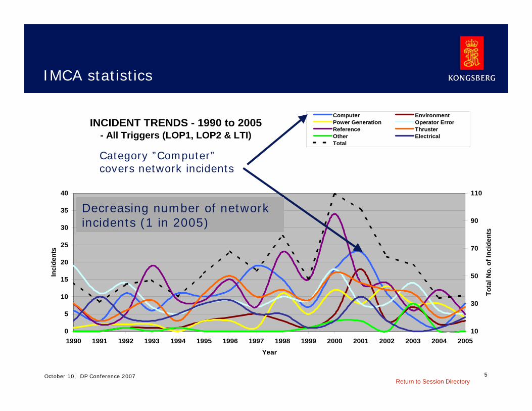
INCIDENT TRENDS - 1990 to 2005- All Triggers (LOP1, LOP2 & LTI)
0
5
10
15
20
25
30
35
40
1990 1991 1992 1993 1994 1995 1996 1997 1998 1999 2000 2001 2002 2003 2004 2005Year
Inci
dent
s
10
30
50
70
90
110
Tota
l No.
of I
ncid
ents
Computer EnvironmentPower Generation Operator ErrorReference ThrusterOther ElectricalTotal
Category ”Computer” covers network incidents
Decreasing number of networkincidents (1 in 2005)
Return to Session Directory
6October 10, DP Conference 2007
Few incidents but still a critical component
Local area networks (LAN) components have improved in stability and capacity
But: LANs are well known from the office, and problems occur ….
And: LAN problems in integrated systems can be very serious
LAN is only one component in the total system, but needsattention
Finding the critical points with FMEA and further verification of system behavior is one solution
Return to Session Directory

7October 10, DP Conference 2007
The FMEA method
Purpose: –Give a description of different failure modes of the
equipment referred to their functional objectives–Detect possible critical points in the system at block level.
DetailedFMEA(Y/N)
Compensatingmeasures
Failureconsequence
Failuredetection
Failuremode
Redundancy(Y/N)
FunctionUnit/Module
ADDITIONAL INFOFAILURE DESCRIPTIONITEM DESCRIPTION
And if relevant: Failure Mode and Effect Analysis (FMEA):Compensating provisions
Failure Effect On Primary (DP) Functions
Failure effect locally (or other)
Detection method
Failure cause(s)
Failure mode
Mode ofoperation
FunctionItem/ Comp.ident
The analysis is performed in two major steps:Preliminary Safety Analysis (PSA)
Return to Session Directory

8October 10, DP Conference 2007
The FMEA test case
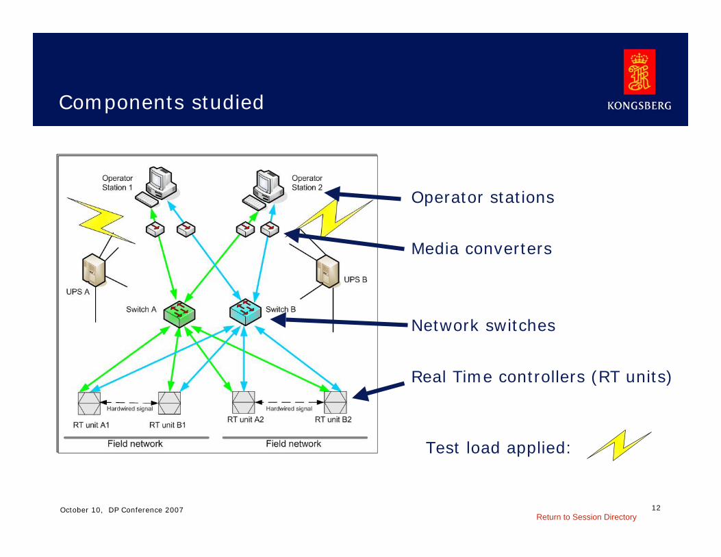
•Duplicated Operator Stations
•Duplicated Real Time units
•Dual network in all units.
•Power segregation (UPS)
•Adm. communication on separate network (not shown)
Return to Session Directory

9October 10, DP Conference 2007
Prerequisites for network FMEA I
•FMEA done for system in normal operation.
•No faults present in relevant components.
•Analysis of the control system software is not included.
•Hardware components are discussed down to real-time controller
•Field data comm. is not included.
•Peripheral equipment like printers, data logging equipment etc. are not analysed.
•The operation mode considered is with relevant UPS power.
Return to Session Directory
10October 10, DP Conference 2007
Prerequisites for network FMEA II
• Failure modes caused by external environments like lightning, fire, flooding are not fully considered.
• Only single errors are generally considered.
• LAN bandwidths up to 100 Mbits/s are considered: LAN topology is based on units which negotiate speed up to 100 Mbits/s, full or half duplex. However, connectionsbetween network switches with 1 Gbits/s are allowed.
• Only items/units with 2 process networks are considered.
• Anti Virus solution, either on the external links or within theOperator stations is supposed to be activated.
Return to Session Directory
11October 10, DP Conference 2007
Failure modes considered
Power failure
Loss of data:on one network interface (i/f)on both network i/f
Transmit erroneous data:on one network i/fon both network i/f
Transmit overload:on one network i/fon both network i/f
Receive overload:on one network i/fon both network i/f
Return to Session Directory
12October 10, DP Conference 2007
Components studied
Operator stations
Media converters
Network switches
Real Time controllers (RT units)
Test load applied:
Return to Session Directory

13October 10, DP Conference 2007
FMEA results
Will stop the RT unit.Transmitoverload on one or both network
RT unit
Can slow down or stop the control functions (double error)
Receive overload on both networks
RT unit
Can slow down or stop the control functions.
Receive overload on one network
RT unit
Can make the station inoperable.
Data receive overload on one network
Operator station
Can make the stationinoperable. (double error)
Data receive overload onboth networks
Operatorstation
Can make the station inoperable and jam the network. (double error)
Data transmitoverload on both networks
Operator station
Station not showing data. No data received on networks. (double error)
Erroneous data receive on both networks
Operatorstation
Problem descriptionFailure modeComp.PSA and FMEA tables is not shown here.
Return to Session Directory
14October 10, DP Conference 2007
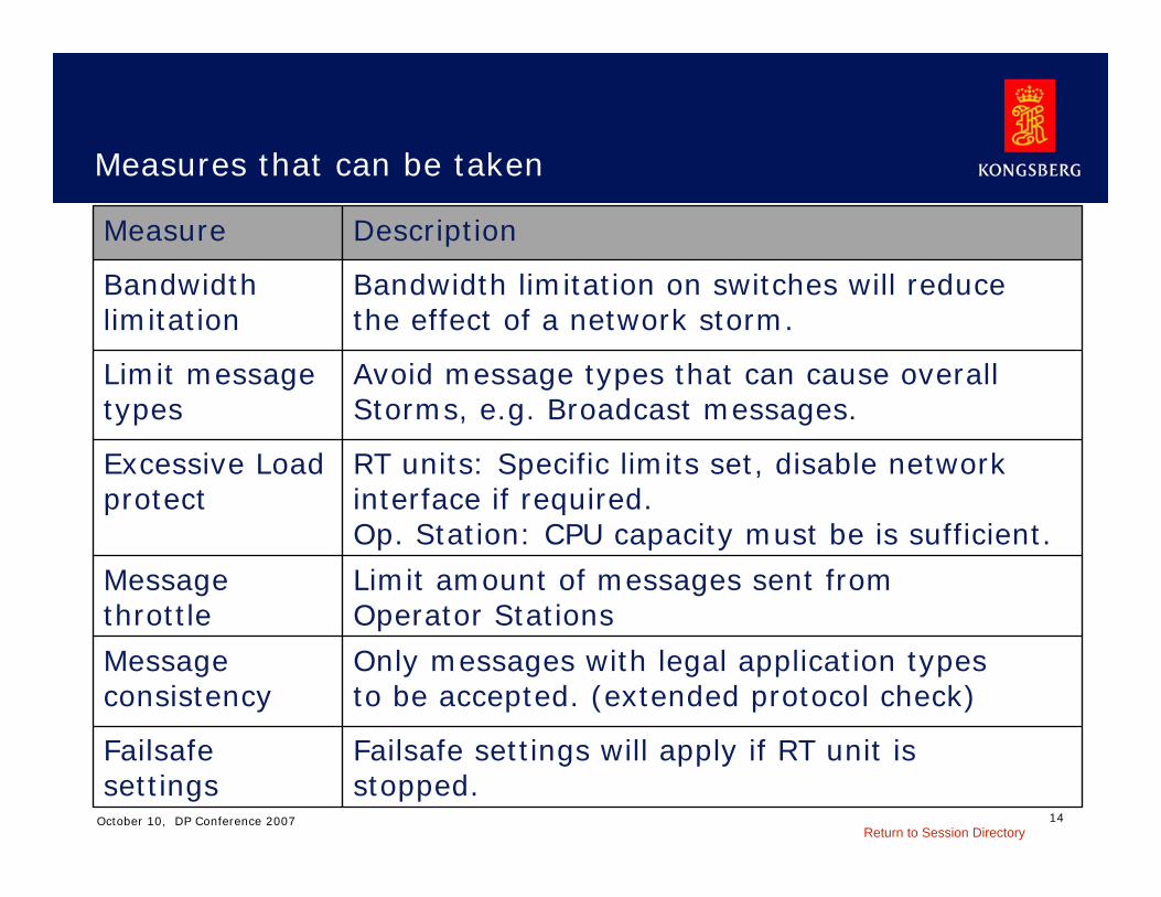
Measures that can be taken
Failsafe settings will apply if RT unit isstopped.
Failsafe settings
Only messages with legal application typesto be accepted. (extended protocol check)
Messageconsistency
Limit amount of messages sent fromOperator Stations
Messagethrottle
RT units: Specific limits set, disable networkinterface if required.Op. Station: CPU capacity must be is sufficient.
Excessive Loadprotect
Avoid message types that can cause overallStorms, e.g. Broadcast messages.
Limit messagetypes
Bandwidth limitation on switches will reducethe effect of a network storm.
Bandwidthlimitation
DescriptionMeasure
Return to Session Directory
15October 10, DP Conference 2007
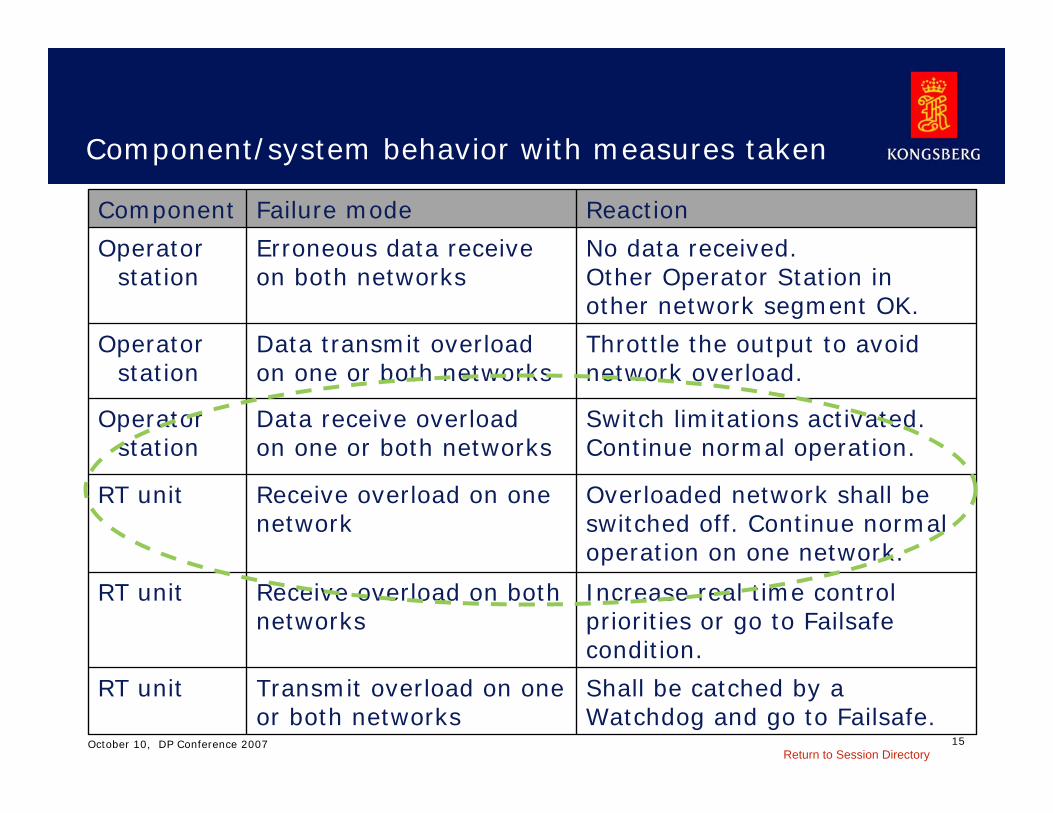
Component/system behavior with measures taken
Shall be catched by a Watchdog and go to Failsafe.
Transmit overload on oneor both networks
RT unit
Increase real time control priorities or go to Failsafe condition.
Receive overload on bothnetworks
RT unit
Overloaded network shall be switched off. Continue normaloperation on one network.
Receive overload on onenetwork
RT unit
Switch limitations activated. Continue normal operation.
Data receive overloadon one or both networks
Operator station
Throttle the output to avoid network overload.
Data transmit overloadon one or both networks
Operator station
No data received.Other Operator Station inother network segment OK.
Erroneous data receiveon both networks
Operator station
ReactionFailure modeComponent
Return to Session Directory
16October 10, DP Conference 2007
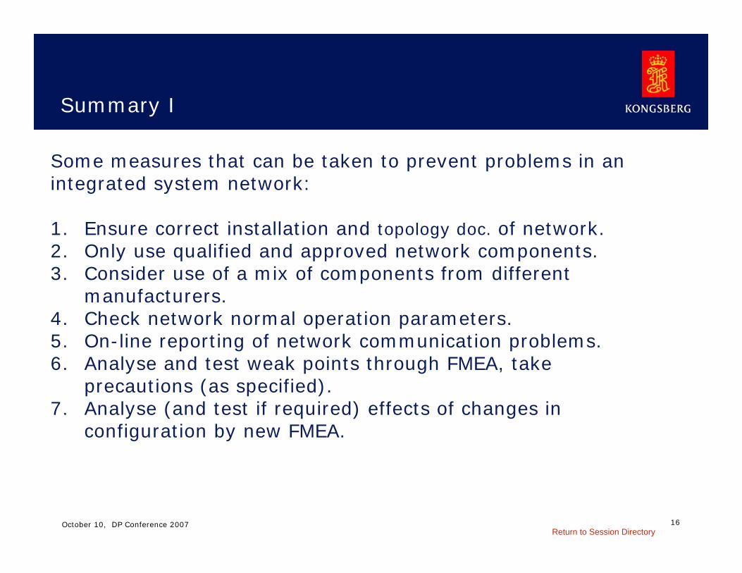
Summary I
Some measures that can be taken to prevent problems in anintegrated system network:
1. Ensure correct installation and topology doc. of network. 2. Only use qualified and approved network components. 3. Consider use of a mix of components from different
manufacturers.4. Check network normal operation parameters. 5. On-line reporting of network communication problems.6. Analyse and test weak points through FMEA, take
precautions (as specified).7. Analyse (and test if required) effects of changes in
configuration by new FMEA.
Return to Session Directory
17October 10, DP Conference 2007
Summary II
Classification societies require documentation for communication networks:
Topology
FMEA
Capacity
Cable routing
FMEA: Experience and implementation!
Return to Session Directory

18© KONGSBERG October 10, DP Conference 2007
WORLD CLASS – through people, technology and dedication
WORLD CLASS – through people, technology and dedication
Integrated control systemsFMEA for networks
Amund R TinderholtKongsberg Maritime
The end
Return to Session Directory