risk assessment for dams and levees -...
TRANSCRIPT
US Army Corps of Engineers BUILDING STRONG®
RISK ASSESSMENT FOR DAMS AND LEVEES Nate Snorteland, P.E. Director, Risk Management Center
Golden, CO
1 October 2011
BUILDING STRONG®
Outline
Dams and Levees Decisions Screening Non-Routine Example Conclusion
BUILDING STRONG®
Critical Risk Integral
happinessbeer =∫
BUILDING STRONG®
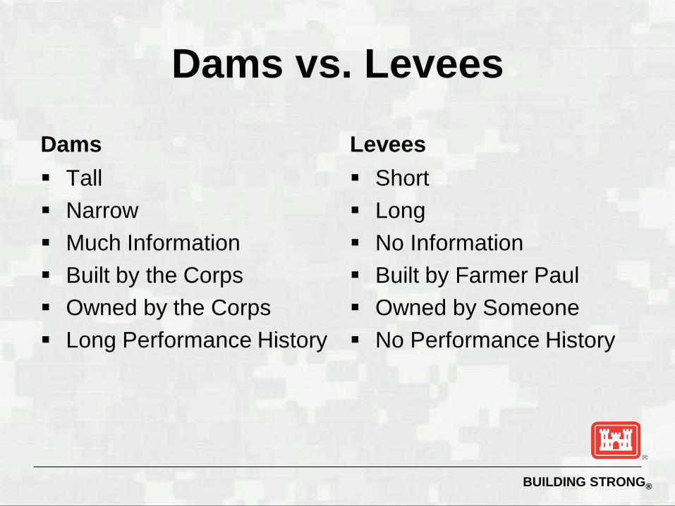
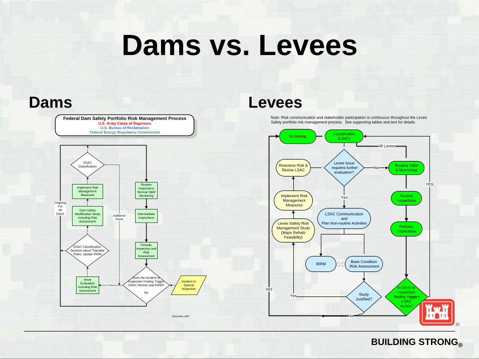
Dams vs. Levees
Dams Tall Narrow Much Information Built by the Corps Owned by the Corps Long Performance History
Levees Short Long No Information Built by Farmer Paul Owned by Someone No Performance History
BUILDING STRONG®
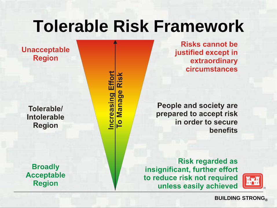
Tolerable Risk Framework
BUILDING STRONG®
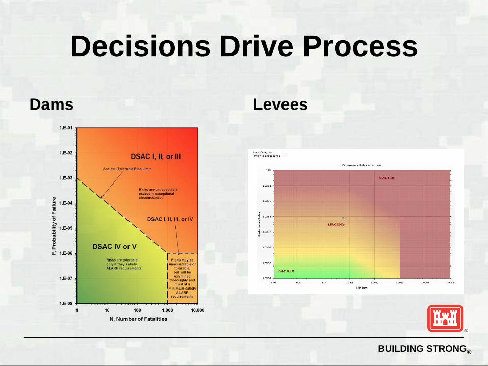
Decisions Drive Process
Dams Levees
BUILDING STRONG®
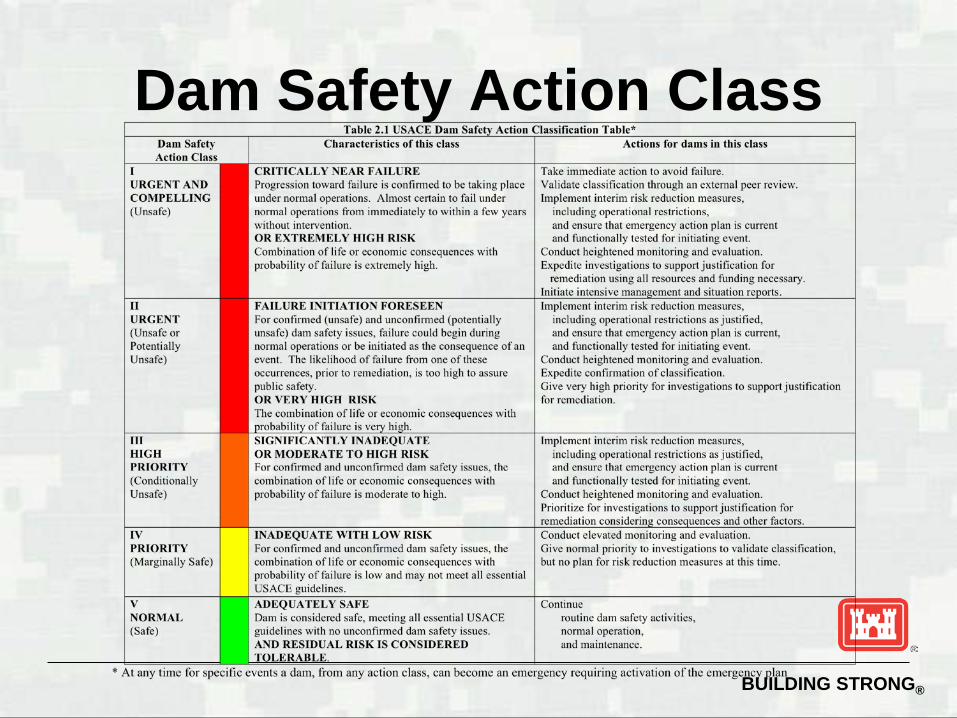
Dam Safety Action Class
BUILDING STRONG®
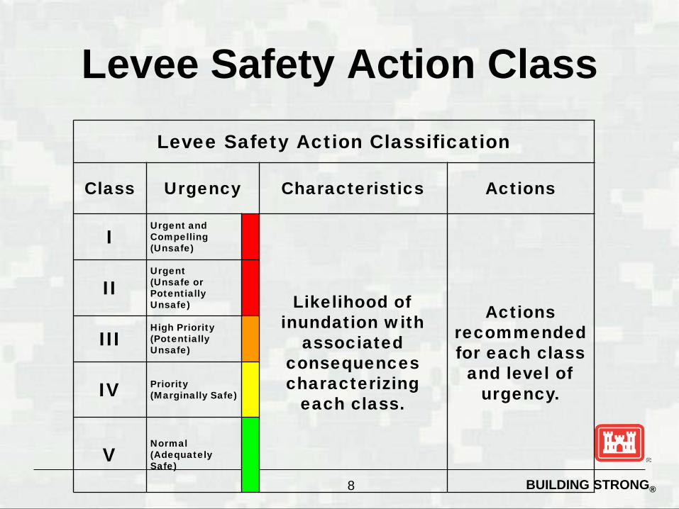
Levee Safety Action Class
8
Levee Safety Action Classification
Class Urgency Characteristics Actions
I Urgent and Compelling (Unsafe)
Likelihood of inundation with
associated consequences characterizing
each class.
Actions recommended for each class
and level of urgency.
II Urgent (Unsafe or Potentially Unsafe)
III High Priority (Potentially Unsafe)
IV Priority (Marginally Safe)
V Normal (Adequately Safe)
BUILDING STRONG®
Dams vs. Levees
Dams Levees
RoutineInspections
Incident or inspection
finding triggers LSAC
review?
NO
IRRM
Levee issue requires further
evaluation?
No
Implement Risk Management
Measures
Yes
Reassess Risk & Revise LSAC
YES
All Levees
PeriodicInspections
Classification(LSAC)Screening
No Routine O&M& Monitoring
Yes
Study Justified?
Base Condition Risk Assessment
LSAC Communicationand
Plan Non-routine ActivitiesLevee Safety Risk Management Study
(Major Rehab/Feasibility)
Note: Risk communication and stakeholder participation is continuous throughout the Levee Safety portfolio risk management process. See supporting tables and text for details.
Routine Inspections
Normal O&M Monitoring
Intermediate Inspections
Periodic Inspection and
Risk Assessment
Issue Evaluation
including Risk Assessment
Does the Incident or Inspection Finding Trigger DSAC Review and IRRM?
No
YesIncident or
Special Inspection
OngoingForAll
Dams
DSAC Classification, Decision about Tolerable
Risks, Update IRRM
Implement Risk Management
Measures
DSAC Classification
Dam Safety Modification Study
including Risk Assessment
AdditionalIssues
Federal Dam Safety Portfolio Risk Management ProcessU.S. Army Corps of Engineers
U.S. Bureau of ReclamationFederal Energy Regulatory Commission
December 2007
BUILDING STRONG®
General Philosophy
Screening – rapid pass through the portfolio Periodic Assessment – recurring
examination of risks Issue Evaluation – trying to decide if risks
are actually issues Modification – trying to decide the best
method to address identified risks
BUILDING STRONG®
Dam Screening
Focus of screening is to make consistent risk evaluations Secondary focus of screening is to make
accurate risk evaluations Less than 4 hours per dam, 7 raters Answer:
►Adequate, Probably Adequate, Probably Inadequate, Inadequate
►OBE, MCE
BUILDING STRONG®
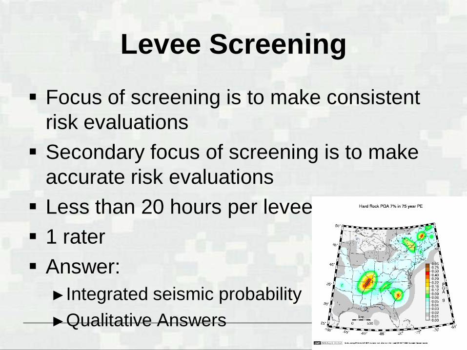
Levee Screening
Focus of screening is to make consistent risk evaluations Secondary focus of screening is to make
accurate risk evaluations Less than 20 hours per levee 1 rater Answer:
►Integrated seismic probability ►Qualitative Answers
BUILDING STRONG®
Screening Objectives
Conservatively determine the likelihood of seismic failure relative to the portfolio of all dams Important conclusions:
►Is it obviously ok? ►Is it obviously a problem? ►Does it require more study? If so, in what
way?
BUILDING STRONG®
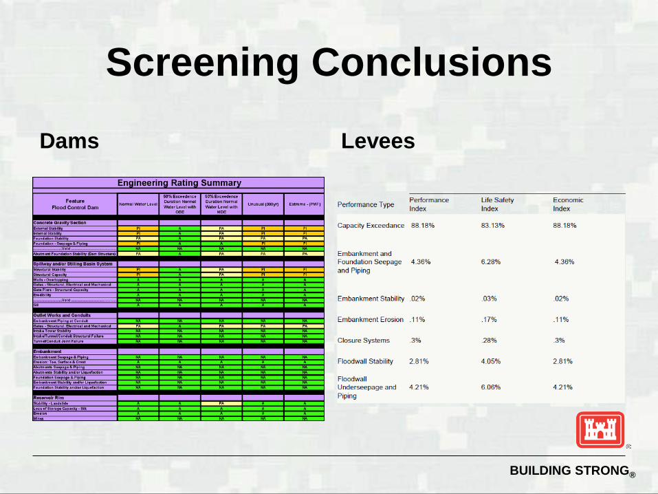
Screening Conclusions
Dams Levees
BUILDING STRONG®
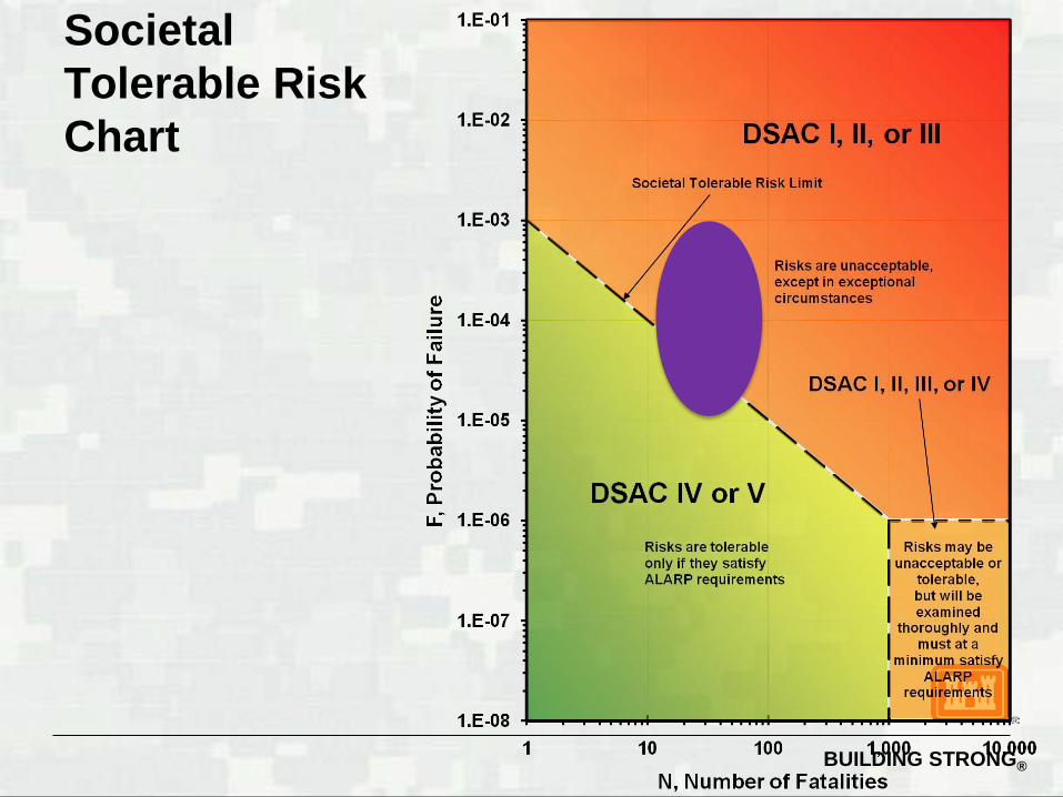
Societal Tolerable Risk Chart
BUILDING STRONG®
Periodic Assessments
Shift focus to failure modes Increase accuracy using event tree
models Increase accuracy with small loss in
consistency Completed by one person Peer reviewed by another person Agency Technical Review Senior Oversight Group
BUILDING STRONG®
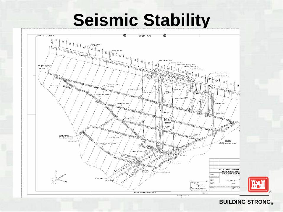
Seismic Stability
BUILDING STRONG®
►PFM 7 Failure of spillway gates due to EQ
►PFM 32 Instability of monolith section with longitudinal (vertical) cracking
►PFM 33 Instability of monolith uncracked sections
Seismic Failure Modes
BUILDING STRONG®
Assumptions remain the same as in hydrologic loading for analysis parameters. ► Phi 79.6 degrees and cohesion 212 psi (mean value)
M19 and M23 analyzed. Horizontal acceleration assumed to be 2/3 PGA. Vertical acceleration assumed to be 0.1 to 0.25 of PGA
(uniformly distributed) ► Values and range decided upon after consultation with Dr. Bob
Ebeling of ERDC
PGA obtained from USGS ground motion calculator.
Seismic Loading External Stability of the Concrete
Dam (PFM#33) – Uncracked Section
BUILDING STRONG®
Seismic Loading
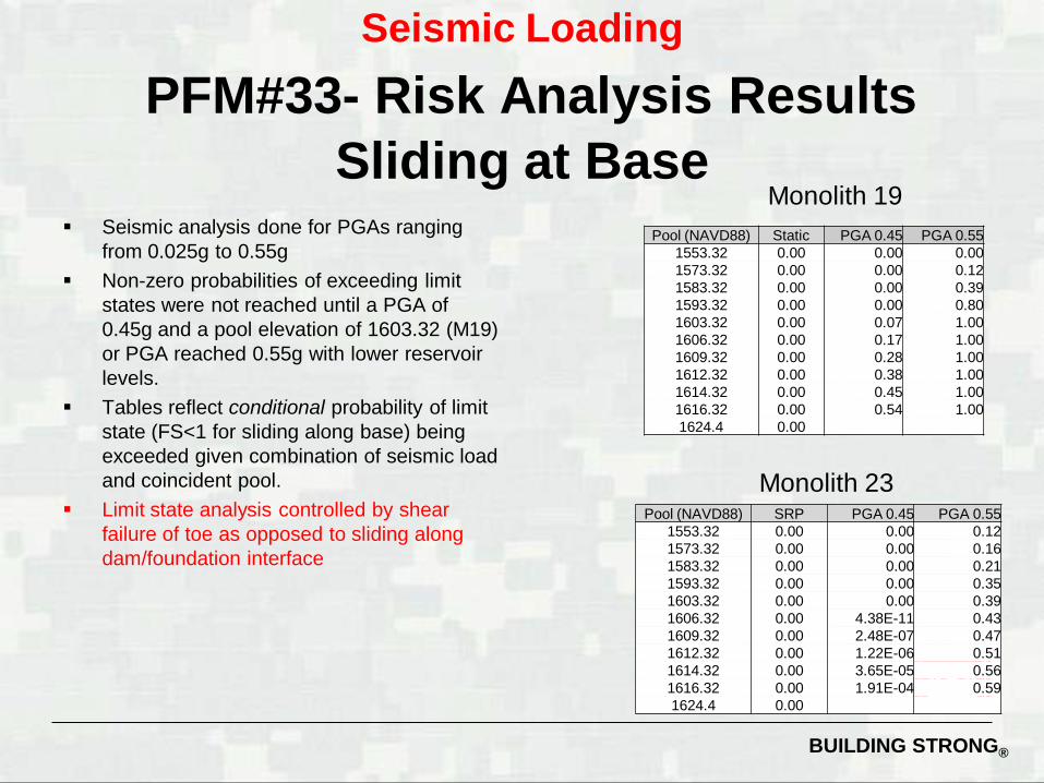
PFM#33- Risk Analysis Results Sliding at Base
Seismic analysis done for PGAs ranging from 0.025g to 0.55g
Non-zero probabilities of exceeding limit states were not reached until a PGA of 0.45g and a pool elevation of 1603.32 (M19) or PGA reached 0.55g with lower reservoir levels.
Tables reflect conditional probability of limit state (FS<1 for sliding along base) being exceeded given combination of seismic load and coincident pool.
Limit state analysis controlled by shear failure of toe as opposed to sliding along dam/foundation interface
Pool (NAVD88) Static PGA 0.45 PGA 0.55 1553.32 0.00 0.00 0.00 1573.32 0.00 0.00 0.12 1583.32 0.00 0.00 0.39 1593.32 0.00 0.00 0.80 1603.32 0.00 0.07 1.00 1606.32 0.00 0.17 1.00 1609.32 0.00 0.28 1.00 1612.32 0.00 0.38 1.00 1614.32 0.00 0.45 1.00 1616.32 0.00 0.54 1.00 1624.4 0.00
Pool (NAVD88) SRP PGA 0.45 PGA 0.55 1553.32 0.00 0.00 0.12 1573.32 0.00 0.00 0.16 1583.32 0.00 0.00 0.21 1593.32 0.00 0.00 0.35 1603.32 0.00 0.00 0.39 1606.32 0.00 4.38E-11 0.43 1609.32 0.00 2.48E-07 0.47 1612.32 0.00 1.22E-06 0.51 1614.32 0.00 3.65E-05 0.56 1616.32 0.00 1.91E-04 0.59 1624.4 0.00
Monolith 19
Monolith 23
BUILDING STRONG®
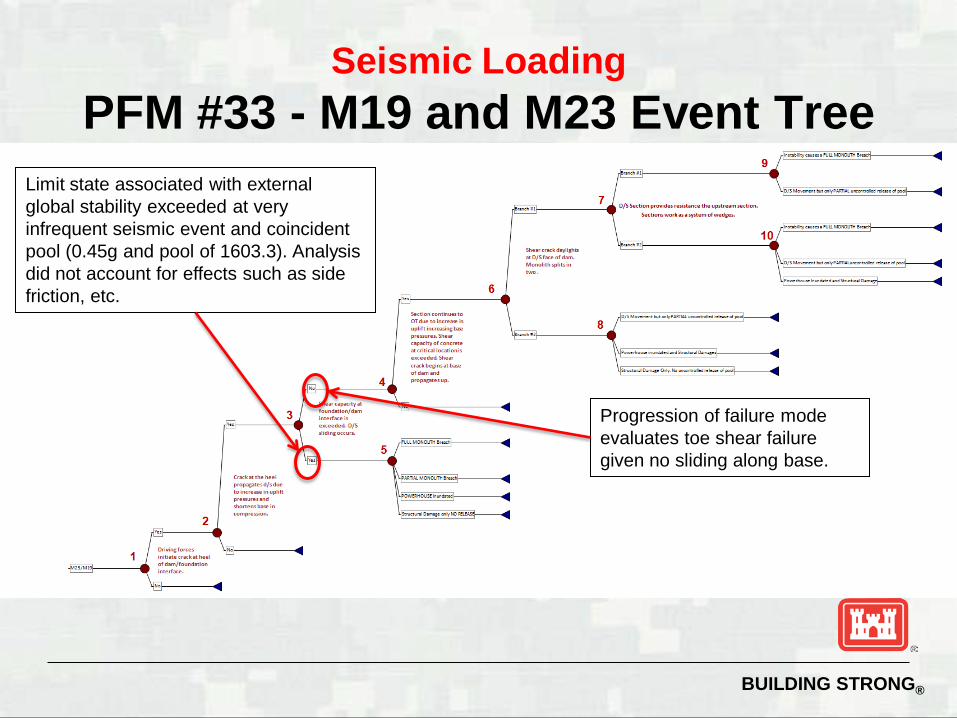
Seismic Loading PFM #33 - M19 and M23 Event Tree
Limit state associated with external global stability exceeded at very infrequent seismic event and coincident pool (0.45g and pool of 1603.3). Analysis did not account for effects such as side friction, etc.
Progression of failure mode evaluates toe shear failure given no sliding along base.
BUILDING STRONG®
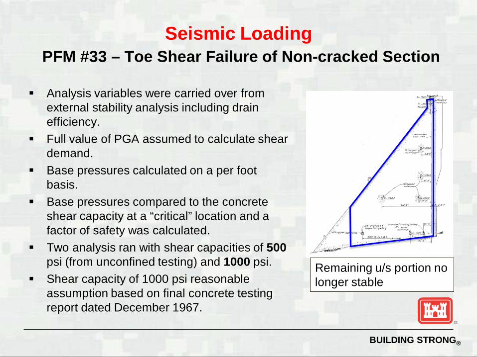
Seismic Loading PFM #33 – Toe Shear Failure of Non-cracked Section
Analysis variables were carried over from external stability analysis including drain efficiency.
Full value of PGA assumed to calculate shear demand.
Base pressures calculated on a per foot basis.
Base pressures compared to the concrete shear capacity at a “critical” location and a factor of safety was calculated.
Two analysis ran with shear capacities of 500 psi (from unconfined testing) and 1000 psi.
Shear capacity of 1000 psi reasonable assumption based on final concrete testing report dated December 1967.
Remaining u/s portion no longer stable
BUILDING STRONG®
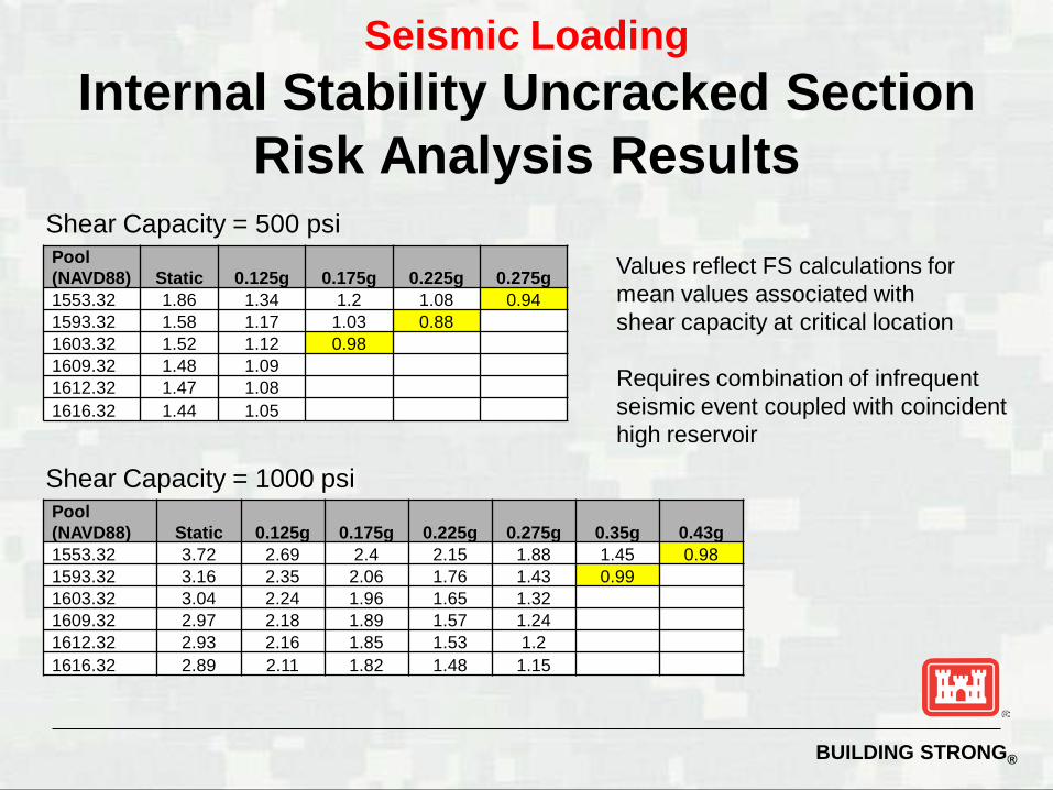
Seismic Loading Internal Stability Uncracked Section
Risk Analysis Results Pool (NAVD88) Static 0.125g 0.175g 0.225g 0.275g 1553.32 1.86 1.34 1.2 1.08 0.94 1593.32 1.58 1.17 1.03 0.88 1603.32 1.52 1.12 0.98 1609.32 1.48 1.09 1612.32 1.47 1.08 1616.32 1.44 1.05
Pool (NAVD88) Static 0.125g 0.175g 0.225g 0.275g 0.35g 0.43g 1553.32 3.72 2.69 2.4 2.15 1.88 1.45 0.98 1593.32 3.16 2.35 2.06 1.76 1.43 0.99 1603.32 3.04 2.24 1.96 1.65 1.32 1609.32 2.97 2.18 1.89 1.57 1.24 1612.32 2.93 2.16 1.85 1.53 1.2 1616.32 2.89 2.11 1.82 1.48 1.15
Shear Capacity = 500 psi
Shear Capacity = 1000 psi
Values reflect FS calculations for mean values associated with shear capacity at critical location Requires combination of infrequent seismic event coupled with coincident high reservoir
BUILDING STRONG®
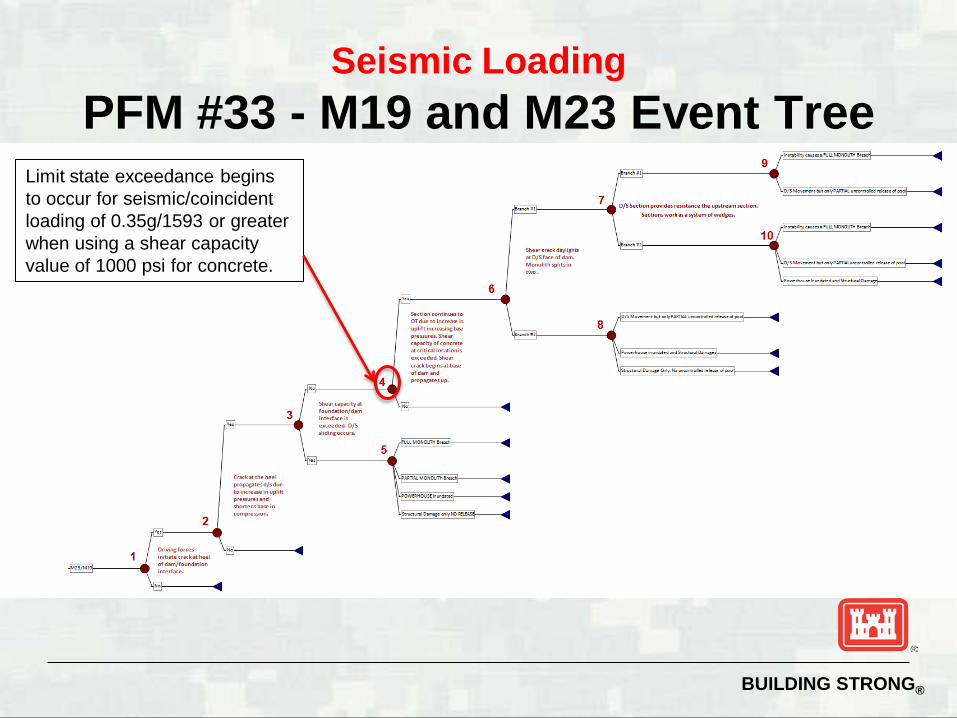
Seismic Loading PFM #33 - M19 and M23 Event Tree
Limit state exceedance begins to occur for seismic/coincident loading of 0.35g/1593 or greater when using a shear capacity value of 1000 psi for concrete.
BUILDING STRONG®
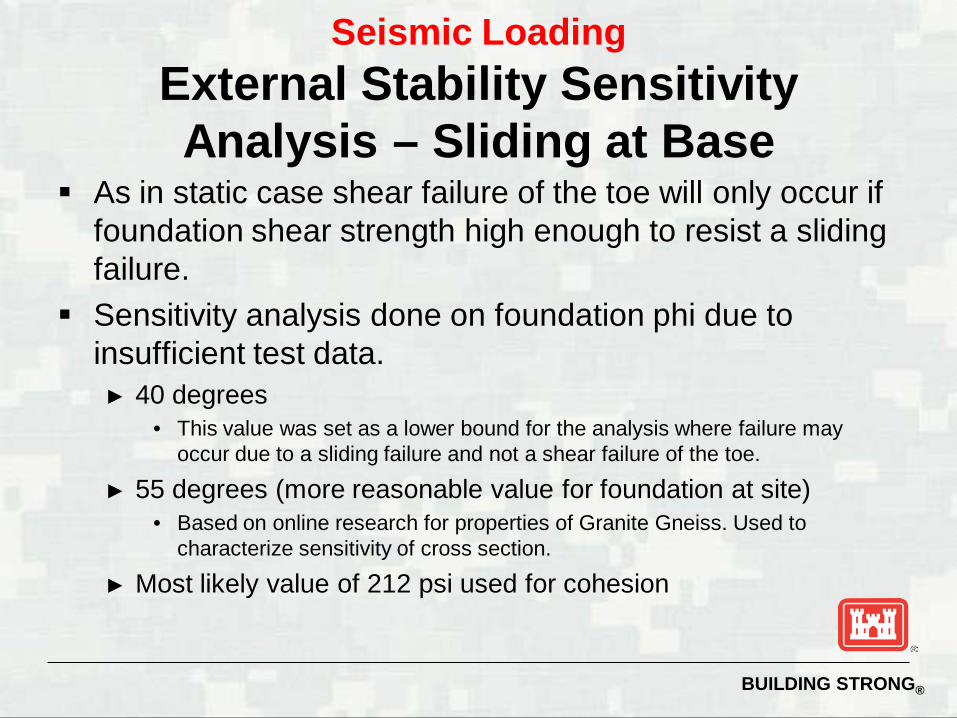
As in static case shear failure of the toe will only occur if foundation shear strength high enough to resist a sliding failure.
Sensitivity analysis done on foundation phi due to insufficient test data. ► 40 degrees
• This value was set as a lower bound for the analysis where failure may occur due to a sliding failure and not a shear failure of the toe.
► 55 degrees (more reasonable value for foundation at site) • Based on online research for properties of Granite Gneiss. Used to
characterize sensitivity of cross section.
► Most likely value of 212 psi used for cohesion
Seismic Loading External Stability Sensitivity Analysis – Sliding at Base
BUILDING STRONG®
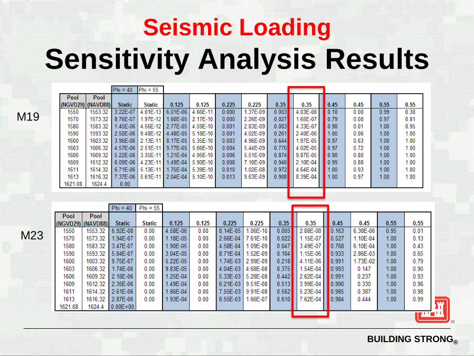
Seismic Loading Sensitivity Analysis Results
M19
M23
BUILDING STRONG®
External stability under seismic loads done with some conservatism ► Slightly lower ranges set on drain efficiency distribution ► No 3D effects taken into account; no consideration of side friction ► M19 only worst case scenario for uplift included in analysis ► Drains no longer effective once crack at the heel progresses
beyond the line of drains. Internal stability of cracked section is the controlling failure mechanism
associated with the monoliths. Monolith M24 has the most extensive vertical cracking.
IES Team and NWW District team both believe that the risk of the concrete dam will be controlled by the internal stability of M24 and not of the uncracked section.
Seismic Loading Conclusions Stability Analysis of
Uncracked Section
BUILDING STRONG®
Seismic Loading Internal Stability of the Concrete Dam (PFM#32) – Cracked Section
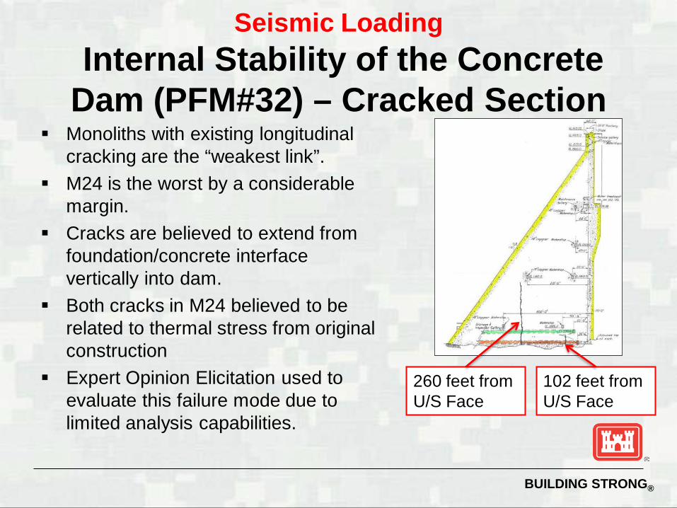
Monoliths with existing longitudinal cracking are the “weakest link”.
M24 is the worst by a considerable margin.
Cracks are believed to extend from foundation/concrete interface vertically into dam.
Both cracks in M24 believed to be related to thermal stress from original construction
Expert Opinion Elicitation used to evaluate this failure mode due to limited analysis capabilities.
102 feet from U/S Face
260 feet from U/S Face
BUILDING STRONG®
Seismic Loading
PFM#32 – Event Tree Cracked Section
BUILDING STRONG®
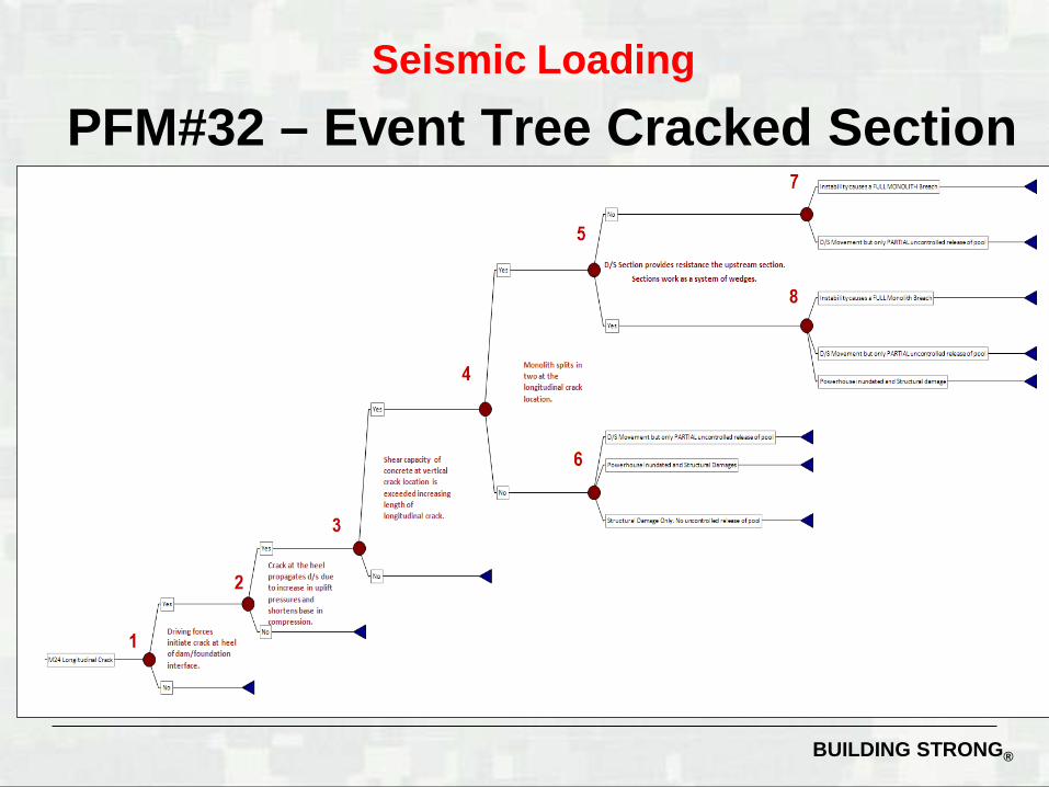
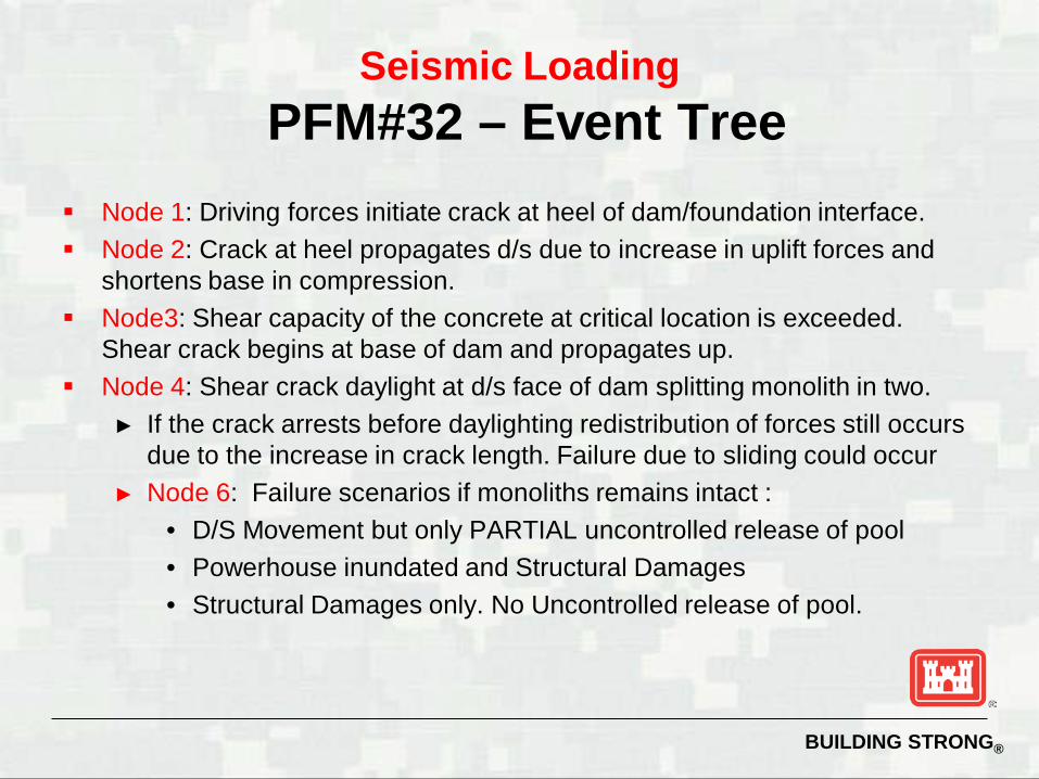
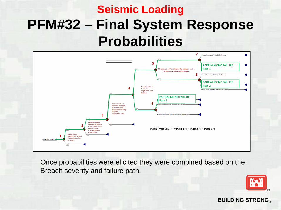
Node 1: Driving forces initiate crack at heel of dam/foundation interface. Node 2: Crack at heel propagates d/s due to increase in uplift forces and
shortens base in compression. Node3: Shear capacity of the concrete at critical location is exceeded.
Shear crack begins at base of dam and propagates up. Node 4: Shear crack daylight at d/s face of dam splitting monolith in two.
► If the crack arrests before daylighting redistribution of forces still occurs due to the increase in crack length. Failure due to sliding could occur
► Node 6: Failure scenarios if monoliths remains intact : • D/S Movement but only PARTIAL uncontrolled release of pool • Powerhouse inundated and Structural Damages • Structural Damages only. No Uncontrolled release of pool.
Seismic Loading PFM#32 – Event Tree
BUILDING STRONG®
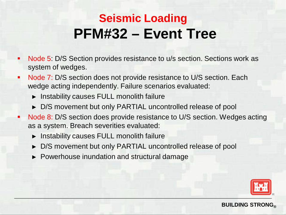
Node 5: D/S Section provides resistance to u/s section. Sections work as system of wedges.
Node 7: D/S section does not provide resistance to U/S section. Each wedge acting independently. Failure scenarios evaluated: ► Instability causes FULL monolith failure ► D/S movement but only PARTIAL uncontrolled release of pool
Node 8: D/S section does provide resistance to U/S section. Wedges acting as a system. Breach severities evaluated: ► Instability causes FULL monolith failure ► D/S movement but only PARTIAL uncontrolled release of pool ► Powerhouse inundation and structural damage
Seismic Loading PFM#32 – Event Tree
BUILDING STRONG®
Seismic acceleration included in elicitation: 0.17g, 0.25g and 0.35g ► These values were chosen based on data available from
external stability analysis done by the IES team and previously FEA done by NWW.
Pool elevations included 1503.32 and 1603.32 ► Based on previous analysis results, probabilities of a shear
failure were more sensitive to changes in seismic loading and not pool loading.
► Team agreed that two pool elevations would capture hydrologic loading range.
Nodes 1 and 2 were assumed to be “virtually certain” to occur based on the loading included in the elicitation.
Nodes 3-10 and 4 failure scenarios were evaluated in the EOE.
Seismic Loading PFM#32
BUILDING STRONG®
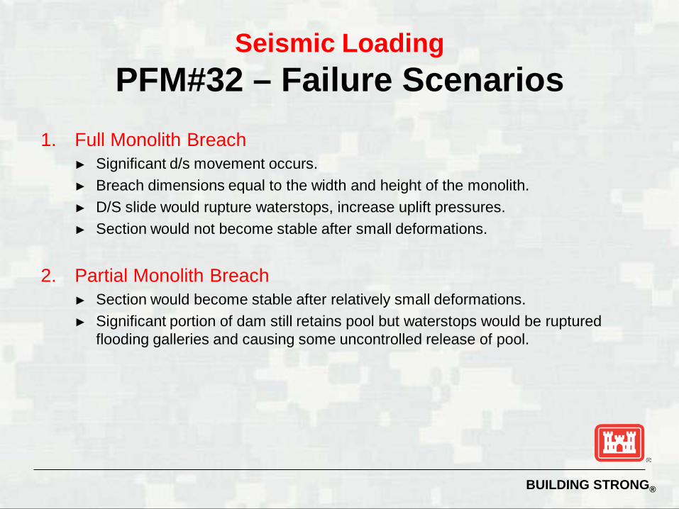
1. Full Monolith Breach ► Significant d/s movement occurs. ► Breach dimensions equal to the width and height of the monolith. ► D/S slide would rupture waterstops, increase uplift pressures. ► Section would not become stable after small deformations.
2. Partial Monolith Breach ► Section would become stable after relatively small deformations. ► Significant portion of dam still retains pool but waterstops would be ruptured
flooding galleries and causing some uncontrolled release of pool.
Seismic Loading PFM#32 – Failure Scenarios
BUILDING STRONG®
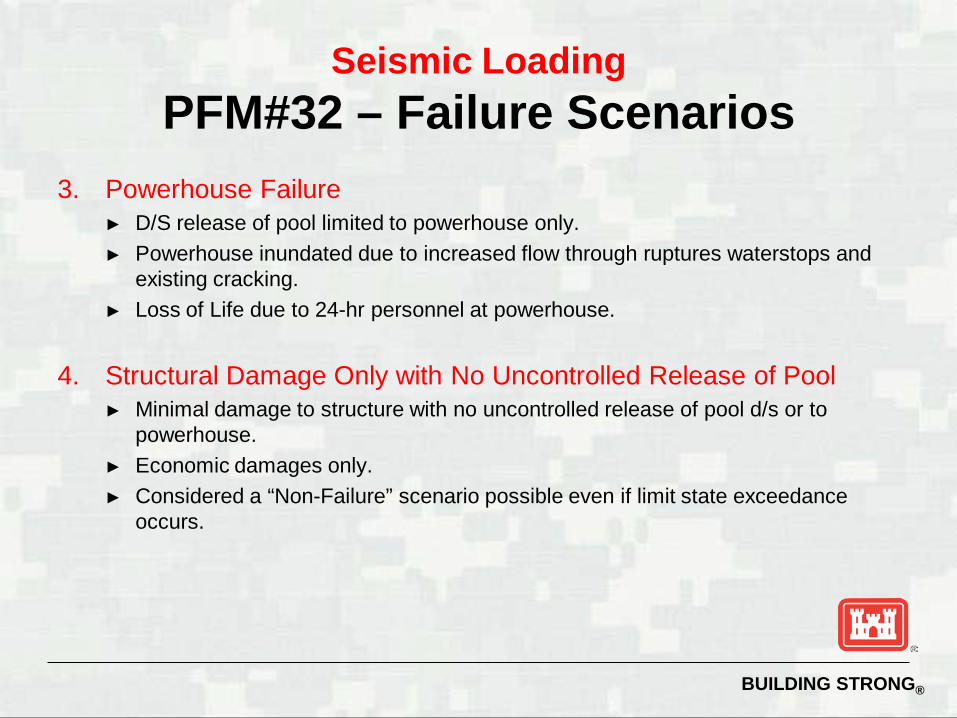
3. Powerhouse Failure ► D/S release of pool limited to powerhouse only. ► Powerhouse inundated due to increased flow through ruptures waterstops and
existing cracking. ► Loss of Life due to 24-hr personnel at powerhouse.
4. Structural Damage Only with No Uncontrolled Release of Pool ► Minimal damage to structure with no uncontrolled release of pool d/s or to
powerhouse. ► Economic damages only. ► Considered a “Non-Failure” scenario possible even if limit state exceedance
occurs.
Seismic Loading PFM#32 – Failure Scenarios
BUILDING STRONG®
Seismic Loading PFM#32 – Final System Response
Probabilities
Once probabilities were elicited they were combined based on the Breach severity and failure path.
BUILDING STRONG®
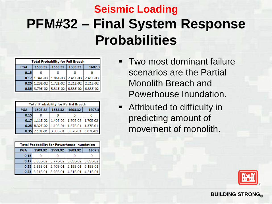
Two most dominant failure scenarios are the Partial Monolith Breach and Powerhouse Inundation.
Attributed to difficulty in predicting amount of movement of monolith.
Seismic Loading PFM#32 – Final System Response
Probabilities
BUILDING STRONG®
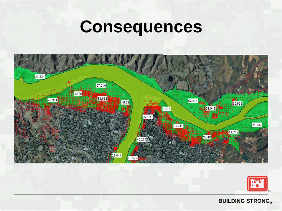
Consequences
BUILDING STRONG®
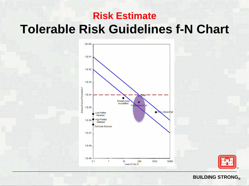
Risk Estimate Tolerable Risk Guidelines f-N Chart
BUILDING STRONG®
Conclusion
Start with the basics Try to be consistent Slowly increase level of effort and detail Continually manage effort and decisions Only do as much as you have to in order
to support the decision to be made