rim & accesso r ies truck & bus tyre rim & accessoriestechnical manual 63 truck &...
TRANSCRIPT

Rim
& A
cc
es
so
Rie
s
Technical data of rims
Tubes and flaps
Mounting and demounting
Tube-type tyre mounting / demounting
Tubeless tyre mounting / demounting
Tubeless rim valve mounting
About dual spacing
Rim & Accessories
TecHNicAL MANUALTruck & Bus Tyre
61TecHNicAL MANUALTruck & Bus Tyre
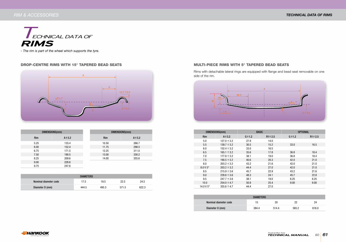
DROP-CENTRE RIMS WITH 15° TAPERED BEAD SEATS MULTI-PIECE RIMS WITH 5° TAPERED BEAD SEATS
DiAmeters
Nominal diameter code 17.5 19.5 22.5 24.5
Diameter D (mm) 444.5 495.3 571.5 622.3
DiAmeters
Nominal diameter code 15 20 22 24
Diameter D (mm) 384.4 514.4 565.2 616.0
DimeNsioNs(mm)
rim A 3.2
5.25 133.46.00 152.46.75 171.57.50 190.58.25 209.69.00 228.69.75 247.6
+-
DimeNsioNs(mm) BAsiC oPtioNAL
rim A 3.2 G 1.2 r1 2.5 G 1.2 r1 2.5
5.0 127.0 3.2 27.9 14.05.5 139.7 3.2 30.5 15.2 33.0 16.56.0 152.4 3.2 33.0 16.56.5 165.1 3.2 35.6 17.8 36.8 18.47.0 177.8 3.2 38.1 19.0 36.8 18.47.5 190.5 3.2 40.6 20.3 42.0 21.08.0 203.2 3.2 43.2 21.6 42.0 21.0
8.0 V 5° 203.2 3.2 44.4 27.0 42.0 21.08.5 215.9 3.6 45.7 22.9 43.2 21.69.0 228.6 3.6 48.3 24.1 45.7 22.89.5 247.7 3.6 38.1 19.0 8.25 8.25
10.0 254.0 4.7 50.8 25.4 9.00 9.0014.0 V 5° 355.6 4.7 44.4 27.0
+-+-+-+-+-+-+-+-+-+-+-+-+-+-
+- +- +- +-
DimeNsioNs(mm)
rim A 3.2
10.50 266.711.75 298.512.25 311.013.00 330.214.00 355.6
+-
Rims with detachable lateral rings are equipped with flange and bead seat removable on one side of the rim.
- The rim is part of the wheel which supports the tyre.
Rim & AccessoRies
riMsTechnical DaTa of
Technical DaTa of Rims
60
63TecHNicAL MANUALTruck & Bus Tyre
62
Rim & AccessoRies Technical DaTa of Rims
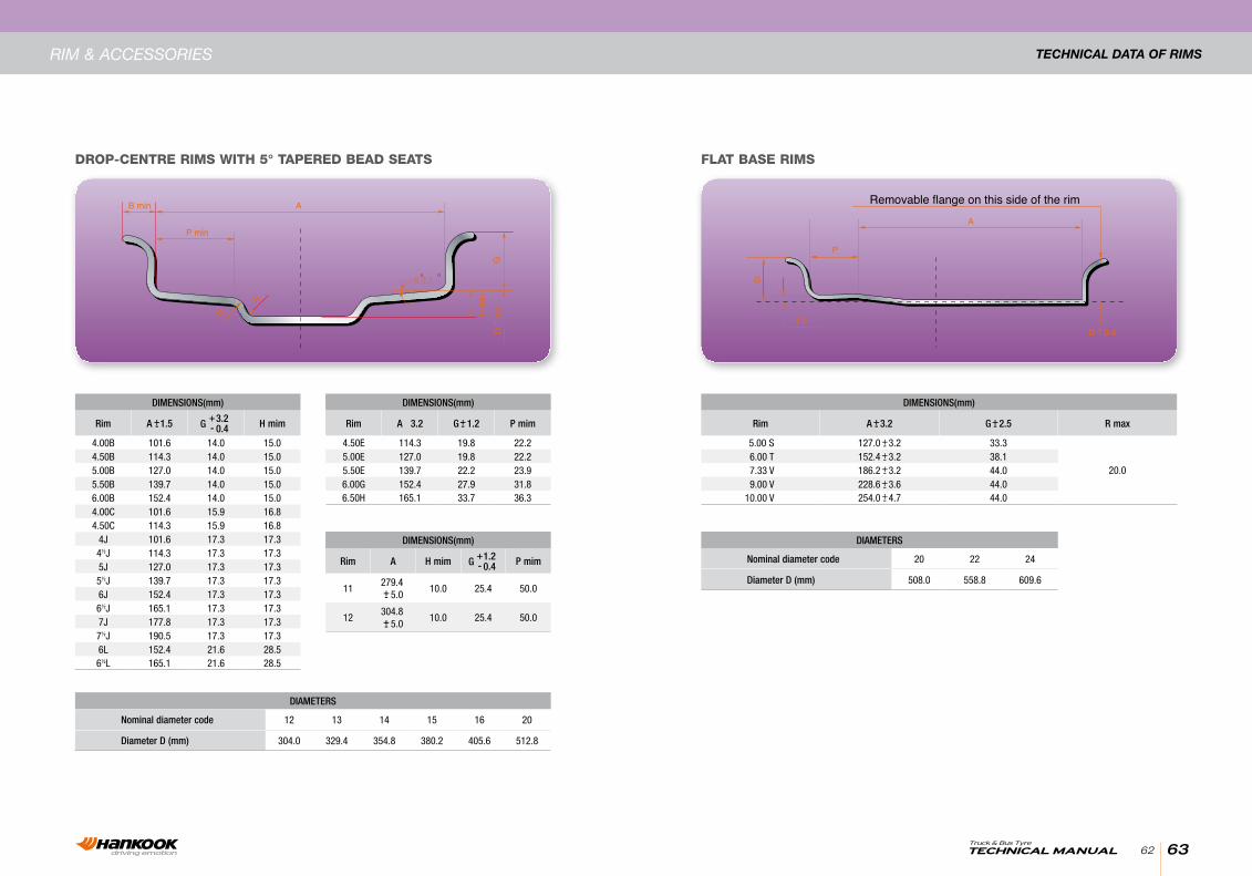
DROP-CENTRE RIMS WITH 5° TAPERED BEAD SEATS FLAT BASE RIMS
DimeNsioNs(mm)
rim A 3.2 G 1.2 P mim
4.50E 114.3 19.8 22.25.00E 127.0 19.8 22.25.50E 139.7 22.2 23.96.00G 152.4 27.9 31.86.50H 165.1 33.7 36.3
+-
DimeNsioNs(mm)
rim A 1.5 3.20.4 h mim
4.00B 101.6 14.0 15.04.50B 114.3 14.0 15.05.00B 127.0 14.0 15.05.50B 139.7 14.0 15.06.00B 152.4 14.0 15.04.00C 101.6 15.9 16.84.50C 114.3 15.9 16.8
4J 101.6 17.3 17.34½J 114.3 17.3 17.35J 127.0 17.3 17.35½J 139.7 17.3 17.36J 152.4 17.3 17.36½J 165.1 17.3 17.37J 177.8 17.3 17.37½J 190.5 17.3 17.36L 152.4 21.6 28.56½L 165.1 21.6 28.5
+-+-G
DimeNsioNs(mm)
rim A 3.2 G 2.5 r max
5.00 S 127.0 3.2 33.3
20.06.00 T 152.4 3.2 38.17.33 V 186.2 3.2 44.09.00 V 228.6 3.6 44.0
10.00 V 254.0 4.7 44.0
+-
+-+-+-+-+-
+-
DiAmeters
Nominal diameter code 12 13 14 15 16 20
Diameter D (mm) 304.0 329.4 354.8 380.2 405.6 512.8
DiAmeters
Nominal diameter code 20 22 24
Diameter D (mm) 508.0 558.8 609.6
DimeNsioNs(mm)
rim A h mim 1.20.4 P mim
11279.4
5.010.0 25.4 50.0
12304.8
5.010.0 25.4 50.0
+-
+-
+-G
65TecHNicAL MANUALTruck & Bus Tyre
64
Tubes anD flaps
FLApsTuBes anD
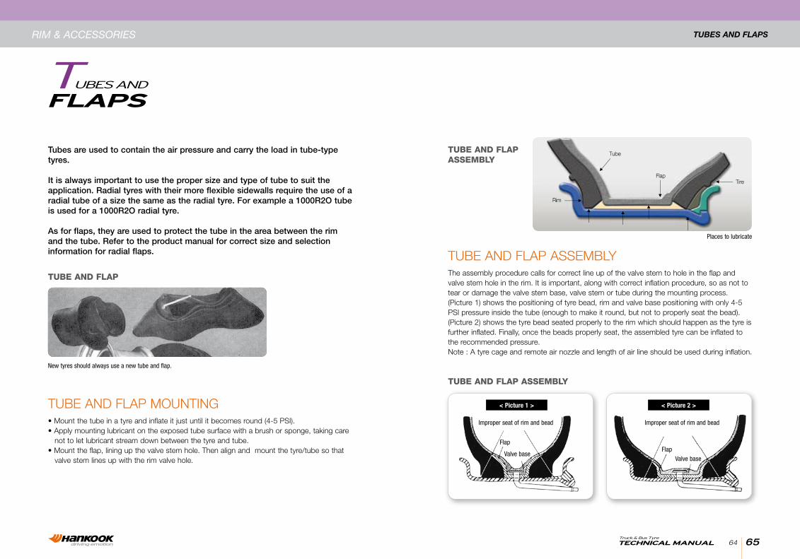
Tube and Flap assemblyThe assembly procedure calls for correct line up of the valve stem to hole in the flap and valve stem hole in the rim. It is important, along with correct inflation procedure, so as not to tear or damage the valve stem base, valve stem or tube during the mounting process.(picture 1) shows the positioning of tyre bead, rim and valve base positioning with only 4-5 psI pressure inside the tube (enough to make it round, but not to properly seat the bead).(picture 2) shows the tyre bead seated properly to the rim which should happen as the tyre is further inflated. Finally, once the beads properly seat, the assembled tyre can be inflated to the recommended pressure.note : a tyre cage and remote air nozzle and length of air line should be used during inflation.
New tyres should always use a new tube and flap.
Places to lubricate
Tube and Flap mounTIng• mount the tube in a tyre and inflate it just until it becomes round (4-5 psI).• apply mounting lubricant on the exposed tube surface with a brush or sponge, taking care not to let lubricant stream down between the tyre and tube.• mount the flap, lining up the valve stem hole. Then align and mount the tyre/tube so that valve stem lines up with the rim valve hole.
Tubes are used to contain the air pressure and carry the load in tube-type tyres.
It is always important to use the proper size and type of tube to suit the application. Radial tyres with their more flexible sidewalls require the use of a radial tube of a size the same as the radial tyre. For example a 1000R2O tube is used for a 1000R2O radial tyre.
As for flaps, they are used to protect the tube in the area between the rim and the tube. Refer to the product manual for correct size and selection information for radial flaps.
TUBE AND FLAP
TUBE AND FLAP ASSEMBLy
TUBE AND FLAP ASSEMBLy
Improper seat of rim and bead Improper seat of rim and bead
FlapFlap
Valve baseValve base
< Picture 1 > < Picture 2 >
Rim & AccessoRies
67TecHNicAL MANUALTruck & Bus Tyre
66
mounTing anD DemounTingRim & AccessoRies
DeMoUNTiNgmounTing anD
saFeTy InsTRucTIonsdo not mount or demount tyres without proper training. Wall charts containing mounting and demounting instructions for all on-highway rims should be available through your normal rim supplier.
REMOvE ALL CRACkED WHEELS FROM SERvICE
LUBRICATE AREAS SHOWN By ARROWS
USE OF GG RING INDICATE CORRECT MOUNTING
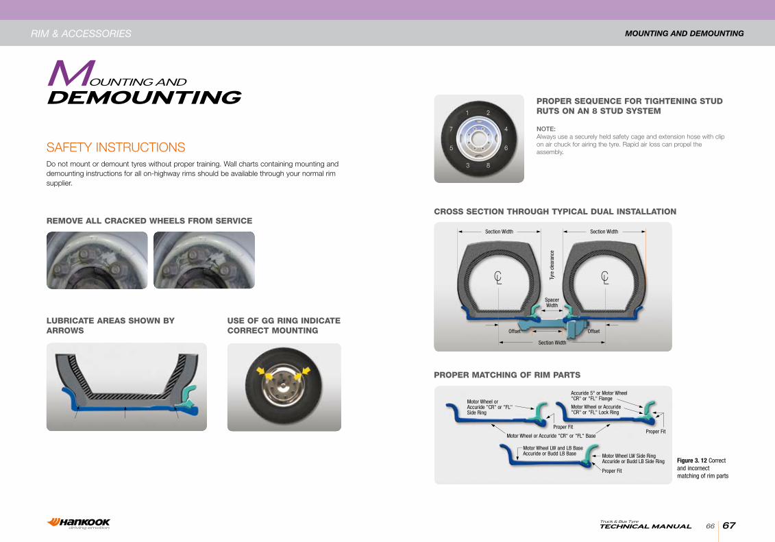
CROSS SECTION THROUGH TyPICAL DUAL INSTALLATION
PROPER SEqUENCE FOR TIGHTENING STUD RUTS ON AN 8 STUD SySTEM
PROPER MATCHING OF RIM PARTS
1 2
3 8
7
5
4
6
NOTE:always use a securely held safety cage and extension hose with clip on air chuck for airing the tyre. Rapid air loss can propel the assembly.
Figure 3. 12 Correct and incornect matching of rim parts
Motor Wheel orAccuride "CR" or "FL"Side Ring
Section Width
OffsetOffset
Tyre
cle
aran
ce
SpacerWidth
Motor Wheel or Accuride"CR" or "FL" Lock Ring
Accuride 5° or Motor Wheel"CR" or "FL" Flange
Motor Wheel or Accuride "CR" or "FL" Base
Motor Wheel LW and LB BaseAccuride or Budd LB Base Motor Wheel LW Side Ring
Accuride or Budd LB Side Ring
Proper FitProper Fit
Proper Fit
Section Width Section Width
69TecHNicAL MANUALTruck & Bus Tyre
68
Tube-Type TyRe mounTingRim & AccessoRies
MoUNTiNgTuBe-Type TyRe
Wheel pRepaRaTIonFor safety reasons check the following in regards to mounting and demounting tyres and wheels.
• rim diameter, rim width and flange design must be that recommended mended for the tyre.• rim profile must be appropriate to the type of tyre(tube-type or tubeless) that is being used.• the angle and position of the tyre bead must seat properly to the rim.
before mounting, the wheel should be inspected for any cracks, breaks, damage, misplaced parts or deformities or irregularities at the locking ring, rim flange, surfaces or valve hole.any signs of weak welds, dents, rough surfaces or rust should be corrected or a new or more suitable wheel should be used.If corroded, clean the rim with a wire brush, sand it smooth and paint it with anti-rust paint.any dents and rough surfaces must be smoothed
NOTE : be careful to demount the tyre prior to attempting any wheel repair such as hammering, heating or welding of wheels.
pRopeR mounTIng and demounTIngFollow all mounting and demounting procedures and equipment safety cautions. always keep tools and work areas clean and free of oil and grease.
NOTE : Tyre mounting lubricant is necessary for mounting and demounting tyres.
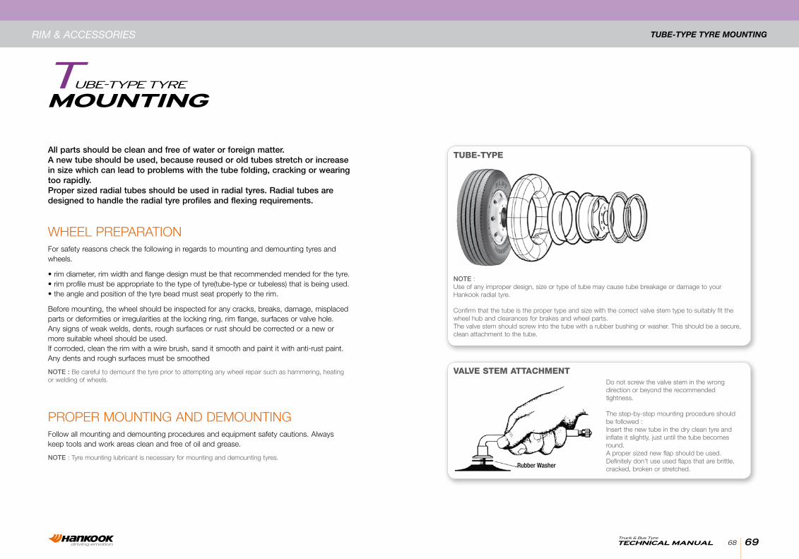
All parts should be clean and free of water or foreign matter.A new tube should be used, because reused or old tubes stretch or increase in size which can lead to problems with the tube folding, cracking or wearing too rapidly.Proper sized radial tubes should be used in radial tyres. Radial tubes are designed to handle the radial tyre profiles and flexing requirements.
NOTE :use of any improper design, size or type of tube may cause tube breakage or damage to your hankook radial tyre.
confirm that the tube is the proper type and size with the correct valve stem type to suitably fit the wheel hub and clearances for brakes and wheel parts.The valve stem should screw into the tube with a rubber bushing or washer. This should be a secure, clean attachment to the tube.
do not screw the valve stem in the wrong direction or beyond the recommended tightness.
The step-by-step mounting procedure should be followed :Insert the new tube in the dry clean tyre and inflate it slightly, just until the tube becomes round.a proper sized new flap should be used. definitely don't use used flaps that are brittle, cracked, broken or stretched.
TUBE-TyPE
vALvE STEM ATTACHMENT
rubber Washer
71TecHNicAL MANUALTruck & Bus Tyre
70
Tube-Type TyRe DemounTingRim & AccessoRies
mount the flap inside the tyre being careful not to buckle the flap edges over or under. centre the flap and position it so that the valve hole lines up. Inflate little more so that flap is held close between tyre and tube. It will not conform perfectly in shape until later.
• after lubricating the rim flange, tyre bead and the flap where it will touch the rim.• slide the tyre/tube/flap assembly onto the rim.• combining the side ring and lightly rap the locking ring into proper position. do not use excessive hammering and avoid hitting the tyre.
saFeTy cauTIonuse an accurate air gauge and an air line and a remote operating nozzle long enough to allow you a distance of personal safety from the tyre assembly for the remainder of the inflation process.
NOTE : do not stand in front of any wheel while inflating the tyre.
• Inflate slightly and recheck to ensure the assembled parts are in the proper position. Inflate slightly more and check to ensure tyre bead has seated (slid over to make complete contact with the rim flange). If not, deflate, lubricate and try re- assembly.• Release any air trapped between the tube, flap and tyre by deflating and then reinflate to get proper conforming fit of the flap.
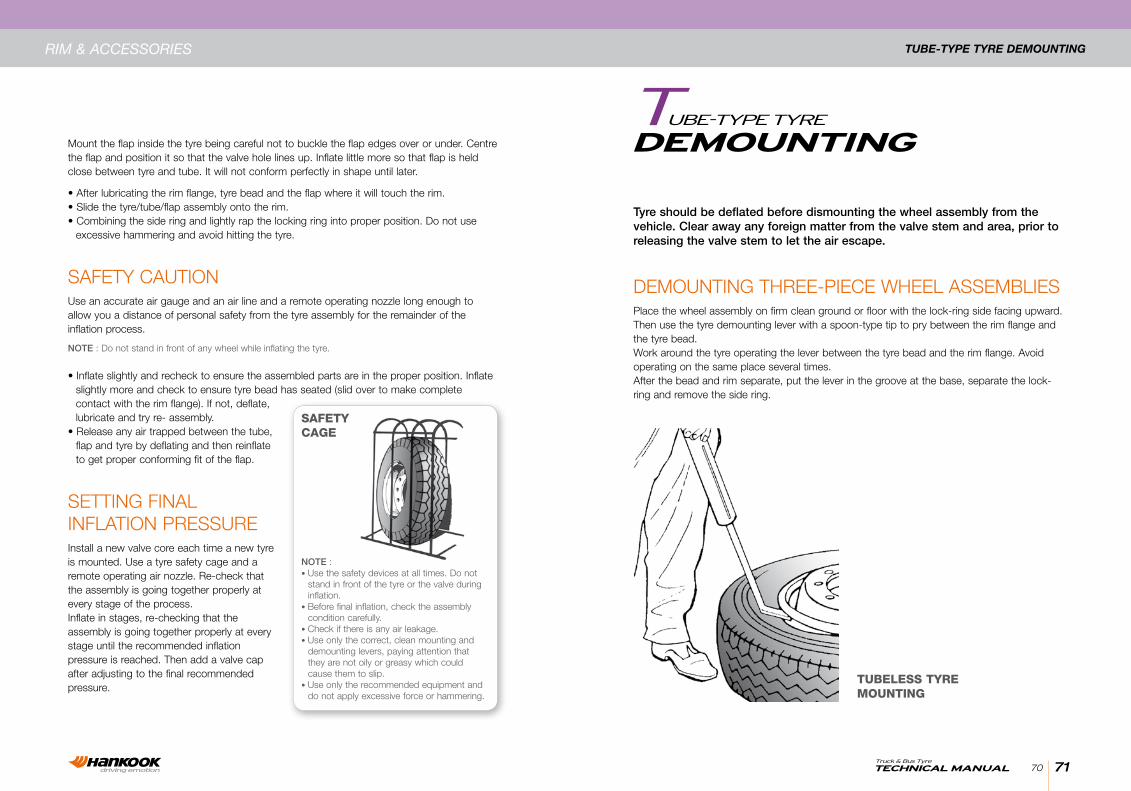
seTTIng FInal InFlaTIon pRessuReInstall a new valve core each time a new tyre is mounted. use a tyre safety cage and a remote operating air nozzle. Re-check that the assembly is going together properly at every stage of the process.Inflate in stages, re-checking that the assembly is going together properly at every stage until the recommended inflation pressure is reached. Then add a valve cap after adjusting to the final recommended pressure.
SAFETy CAGE
NOTE :• use the safety devices at all times. do not stand in front of the tyre or the valve during inflation.• before final inflation, check the assembly condition carefully.• check if there is any air leakage.• use only the correct, clean mounting and demounting levers, paying attention that they are not oily or greasy which could cause them to slip.• use only the recommended equipment and do not apply excessive force or hammering.
Tyre should be deflated before dismounting the wheel assembly from the vehicle. Clear away any foreign matter from the valve stem and area, prior to releasing the valve stem to let the air escape.
DeMoUNTiNgTuBe-Type TyRe
demounTIng ThRee-pIece Wheel assemblIesplace the wheel assembly on firm clean ground or floor with the lock-ring side facing upward. Then use the tyre demounting lever with a spoon-type tip to pry between the rim flange and the tyre bead.Work around the tyre operating the lever between the tyre bead and the rim flange. avoid operating on the same place several times.after the bead and rim separate, put the lever in the groove at the base, separate the lock-ring and remove the side ring.
TUBELESS TyRE MOUNTING
73TecHNicAL MANUALTruck & Bus Tyre
72
Tubeless TyRe mounTingRim & AccessoRies
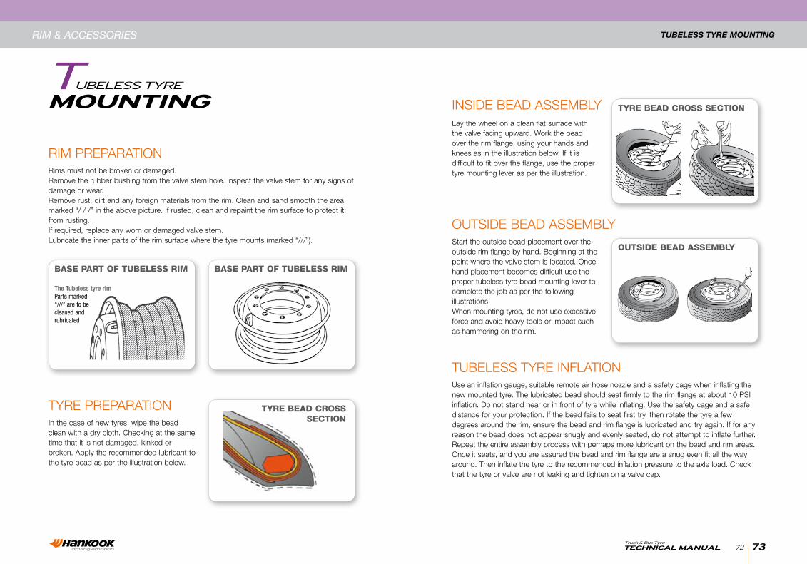
BASE PART OF TUBELESS RIM
TyRE BEAD CROSS SECTION
OUTSIDE BEAD ASSEMBLy
BASE PART OF TUBELESS RIM
The Tubeless tyre rimParts marked“///” are to becleaned andrubricated
TyRe pRepaRaTIonIn the case of new tyres, wipe the bead clean with a dry cloth. checking at the same time that it is not damaged, kinked or broken. apply the recommended lubricant to the tyre bead as per the illustration below.
ouTsIde bead assemblystart the outside bead placement over the outside rim flange by hand. beginning at the point where the valve stem is located. once hand placement becomes difficult use the proper tubeless tyre bead mounting lever to complete the job as per the following illustrations.When mounting tyres, do not use excessive force and avoid heavy tools or impact such as hammering on the rim.
Tubeless TyRe InFlaTIonuse an inflation gauge, suitable remote air hose nozzle and a safety cage when inflating the new mounted tyre. The lubricated bead should seat firmly to the rim flange at about 10 psI inflation. do not stand near or in front of tyre while inflating. use the safety cage and a safe distance for your protection. If the bead fails to seat first try, then rotate the tyre a few degrees around the rim, ensure the bead and rim flange is lubricated and try again. If for any reason the bead does not appear snugly and evenly seated, do not attempt to inflate further. Repeat the entire assembly process with perhaps more lubricant on the bead and rim areas.once it seats, and you are assured the bead and rim flange are a snug even fit all the way around. Then inflate the tyre to the recommended inflation pressure to the axle load. check that the tyre or valve are not leaking and tighten on a valve cap.
InsIde bead assemblylay the wheel on a clean flat surface with the valve facing upward. Work the bead over the rim flange, using your hands and knees as in the illustration below. If it is difficult to fit over the flange, use the proper tyre mounting lever as per the illustration.
RIm pRepaRaTIonRims must not be broken or damaged.Remove the rubber bushing from the valve stem hole. Inspect the valve stem for any signs of damage or wear.Remove rust, dirt and any foreign materials from the rim. clean and sand smooth the area marked “/ / /” in the above picture. If rusted, clean and repaint the rim surface to protect it from rusting.If required, replace any worn or damaged valve stem.lubricate the inner parts of the rim surface where the tyre mounts (marked “///”).
TyRE BEAD CROSS SECTION
MoUNTiNgTuBeless TyRe
75TecHNicAL MANUALTruck & Bus Tyre
74
Tubeless TyRe DemounTingRim & AccessoRies
DeMoUNTiNgTuBeless TyRe
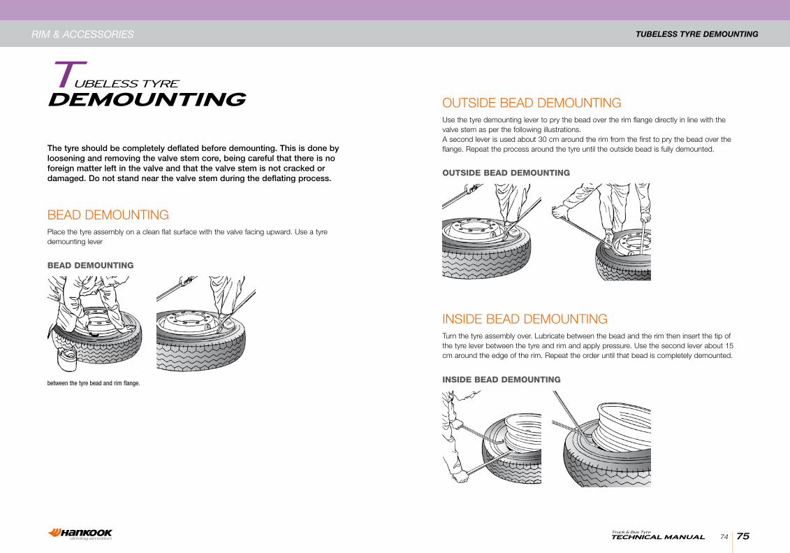
bead demounTIngplace the tyre assembly on a clean flat surface with the valve facing upward. use a tyre demounting lever
ouTsIde bead demounTInguse the tyre demounting lever to pry the bead over the rim flange directly in line with the valve stem as per the following illustrations.a second lever is used about 30 cm around the rim from the first to pry the bead over the flange. Repeat the process around the tyre until the outside bead is fully demounted.
InsIde bead demounTIngTurn the tyre assembly over. lubricate between the bead and the rim then insert the tip of the tyre lever between the tyre and rim and apply pressure. use the second lever about 15 cm around the edge of the rim. Repeat the order until that bead is completely demounted.
The tyre should be completely deflated before demounting. This is done by loosening and removing the valve stem core, being careful that there is no foreign matter left in the valve and that the valve stem is not cracked or damaged. Do not stand near the valve stem during the deflating process.
BEAD DEMOUNTING
OUTSIDE BEAD DEMOUNTING
INSIDE BEAD DEMOUNTINGbetween the tyre bead and rim flange.

77TecHNicAL MANUALTruck & Bus Tyre
76
Tubeless Rim valve mounTingRim & AccessoRies
VALVe MoUNTiNgTuBeless Rim
a-Type RIm ValVeThe valve hole in the rim must be clean, smooth and not damaged. apply a recommended lubricant to the rubber bushing of the valve. Insert the valve stem through the rim hole, assembling the washer and lock-nut on the inside and tighten the lock-nut with a wrench so that the valve stem is secured to the rim.
c-Type RIm ValVeThe valve hole in the rim must be clean, smooth and not damaged. as per the illustration below, lubricate the 0-ring and insert a new valve stem through the 0-ring and then through the valve stem hole in the rim from the inside. From the other side, securely hand tighten on the lock nut.
b-Type RIm ValVeThe valve hole in the rim must be clean, smooth and not damaged. as per the illustration below place a lubricated 0-ring on the valve stem, insert the stem into the valve stem hole in the rim so that the valve faces perpendicular to the rim. Then tighten the lock nut with a wrench from the opposite side of the rim until the valve stem is secure.
C-TyPE RIM vALvE
Valve O-ring
Lock-nutValve cap
B-TyPE RIM vALvE
Lock nut
O-ring
ValveValve cap
A-TyPE RIM vALvE
Rubber bushing
Washer
Lock nut
Valve cap
Valve stem
79TecHNicAL MANUALTruck & Bus Tyre
78
abouT Dual spacingRim & AccessoRies
DUAL spAciNgaBouT
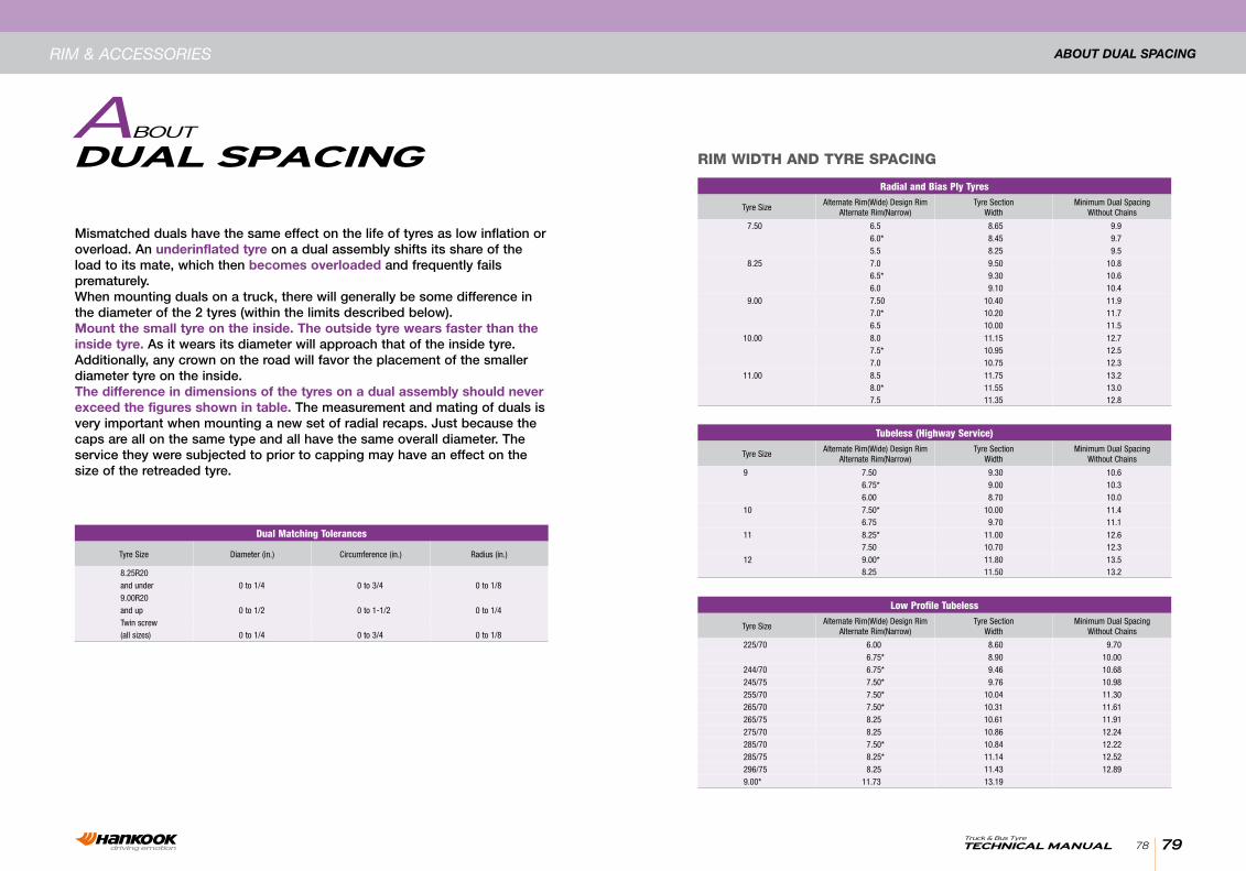
Mismatched duals have the same effect on the life of tyres as low inflation or overload. An underinflated tyre on a dual assembly shifts its share of the load to its mate, which then becomes overloaded and frequently fails prematurely.When mounting duals on a truck, there will generally be some difference in the diameter of the 2 tyres (within the limits described below).Mount the small tyre on the inside. The outside tyre wears faster than the inside tyre. As it wears its diameter will approach that of the inside tyre. Additionally, any crown on the road will favor the placement of the smaller diameter tyre on the inside.The difference in dimensions of the tyres on a dual assembly should never exceed the figures shown in table. The measurement and mating of duals is very important when mounting a new set of radial recaps. Just because the caps are all on the same type and all have the same overall diameter. The service they were subjected to prior to capping may have an effect on the size of the retreaded tyre.
RIM WIDTH AND TyRE SPACING
Radial and Bias Ply Tyres
Tyre SizeAlternate Rim(Wide) Design Rim
Alternate Rim(Narrow)Tyre Section
WidthMinimum Dual Spacing
Without Chains
7.50 6.5 8.65 9.96.0* 8.45 9.75.5 8.25 9.5
8.25 7.0 9.50 10.86.5* 9.30 10.66.0 9.10 10.4
9.00 7.50 10.40 11.97.0* 10.20 11.76.5 10.00 11.5
10.00 8.0 11.15 12.77.5* 10.95 12.57.0 10.75 12.3
11.00 8.5 11.75 13.28.0* 11.55 13.07.5 11.35 12.8
Low Profile Tubeless
Tyre SizeAlternate Rim(Wide) Design Rim
Alternate Rim(Narrow)Tyre Section
WidthMinimum Dual Spacing
Without Chains
225/70 6.00 8.60 9.70 6.75* 8.90 10.00
244/70 6.75* 9.46 10.68245/75 7.50* 9.76 10.98255/70 7.50* 10.04 11.30265/70 7.50* 10.31 11.61265/75 8.25 10.61 11.91275/70 8.25 10.86 12.24285/70 7.50* 10.84 12.22285/75 8.25* 11.14 12.52296/75 8.25 11.43 12.899.00* 11.73 13.19
Tubeless (Highway Service)
Tyre SizeAlternate Rim(Wide) Design Rim
Alternate Rim(Narrow)Tyre Section
WidthMinimum Dual Spacing
Without Chains
9 7.50 9.30 10.66.75* 9.00 10.36.00 8.70 10.0
10 7.50* 10.00 11.46.75 9.70 11.1
11 8.25* 11.00 12.67.50 10.70 12.3
12 9.00* 11.80 13.58.25 11.50 13.2
Dual Matching Tolerances
Tyre Size Diameter (in.) Circumference (in.) Radius (in.)
8.25R20and under 0 to 1/4 0 to 3/4 0 to 1/89.00R20and up 0 to 1/2 0 to 1-1/2 0 to 1/4Twin screw(all sizes) 0 to 1/4 0 to 3/4 0 to 1/8