rigorous engineering of product-line requirements: a case
TRANSCRIPT
Rigorous engineering of product-line requirements: acase study in failure management
Colin Snook a, Michael Poppleton a,∗, Ian Johnson b
aSchool of Electronics and Computer Science, University of Southampton, Highfield,Southampton SO17 1BJ, UK
bAT Engine Controls, Portsmouth
Abstract
We consider the failure detection and management function for engine control systems asan application domain where product line engineering is indicated. The need to develop ageneric requirement set - for subsequent system instantiation - is complicated by the addi-tion of the high levels of verification demanded by this safety-critical domain, subject toavionics industry standards. We present our case study experience in this area as a candi-date method for the engineering, validation and verification of generic requirements usingdomain engineering and Formal Methods techniques and tools. For a defined class of sys-tems, the case study produces a generic requirement set in UML and an example systeminstance. Domain analysis and engineering produce a validated model which is integratedwith the formal specification/ verification method B by the use of our UML-B profile. Theformal verification both of the generic requirement set, and of a simple system instance, isdemonstrated using our U2B, ProB and prototype Requirements Manager tools.
This work is a demonstrator for a tool-supported method which will be an output of EUproject RODIN 1 . The use of existing and prototype formal verification and support toolsis discussed. The method, developed in application to this novel combination of productline, failure management and safety-critical engineering, is evaluated and considered to beapplicable to a wide range of domains.
Key words: formal specification, generic requirements, product line, refinement, tools,UML-B, verification
1 This work is conducted in the setting of the EU funded research project: IST511599 RODIN (Rigorous Open Development Environment for Complex Systems)http://rodin.cs.ncl.ac.uk/.∗ Corresponding author
Email addresses: [email protected] (Colin Snook),[email protected] (Michael Poppleton),[email protected] (Ian Johnson).
Preprint submitted to Elsevier Science 12 February 2007

1 Introduction
The notion of software product line (also known as system family) engineering be-came well established [29], after Parnas’ proposal [35] in the 70’s of informationhiding and modularization as techniques that would support the handling of pro-gram families. Product line engineering arises where multiple variants of essentiallythe same software system are required, to meet a variety of platform, functional, orother requirements. This kind of generic systems engineering is well known in theavionics industry; e.g. [25,19] describe the reuse of generic sets of requirements inengine control and flight control systems.
Domain analysis and object oriented frameworks are among numerous solutionsproposed to product line technology. In Domain-Specific Software Architecture[44] for example, the domain engineering of a set of general, domain-specific re-quirements for the product line is followed by its successive refinement, in a seriesof system engineering cycles, into specific product requirements. On the other hand[20] describes the Object-Oriented Framework as a “a reusable, semi-complete ap-plication that can be specialized to produce custom applications”. Here the domainengineering produces an object-oriented model that must be instantiated, in somesystematic way, for each specific product required. In this work we combine object-oriented and formal techniques and tools in domain and product line engineering.
Developers in the avionics industry are interested in the use of object-oriented andUML technology (OOT) [11,32] as a way to increase productivity. Concepts suchas inheritance and design patterns facilitate the reuse of requirements and designs.UML has emerged as the de-facto standard modelling language for object-orienteddesign and analysis, supported by a wide variety of tools. Due to concerns oversafety certification issues however, OOT has not seen widespread use in avionicsapplications. The controlling standards used in the industry, such as RTCA DO-178B [21] and its European equivalent, EUROCAE ED-12B [1], do not considerOOT, although this is under review.
It is widely recognized that formal methods (FM) technology makes a strong con-tribution to the verification required for safety-critical systems; indeed, DefStan00-55 [33] as well as the avionics standards above recommend the use of FM forcritical systems. It is further recognized that FM will need to be integrated [5] -in as “black-box” as possible a manner - with OOT in order to achieve serious in-dustry penetration. The combination of UML and formal methods therefore offersthe promise of improved safety and flexibility in the design of software for aviationcertification.
One approach to the integration of FM and OOT is to enhance - at the abstractmodelling stage - UML with the minimum amount of textual formal specificationrequired to completely express functional, safety and other requirements. A tool
2
will convert the customer-oriented abstract UML model to a fully textual model asinput to FM tools such as model-checkers and theorem provers. With suitable toolsupport for configuration and project management, this approach will facilitate thereuse of verified software specifications and consequently code components.
Adoption of formal methods in the safety-critical industry has been limited partlydue to the need for industrial strength tool support. The B method of J.-R. Abrial[2,39] is a formal method with good tool support, and a good industrial trackrecord, e.g. [17]. An approach that integrates formal specification and verificationin the B language, with UML-based design methods, has been under developmentat Southampton for some years. The UML-B [42] is a profile of UML that defines aformal modelling notation combining UML and B. It is supported by the U2B tool[40], which translates UML-B models into B, for subsequent formal verification.This verification includes model-checking with the ProB model-checker [27] for B.These tools have all been developed at Southampton, and continue to be extended incurrent work in project RODIN, which aims to produce the next-generation Event-B method and tools.
1.1 Failure detection and management (FDM) for engine control
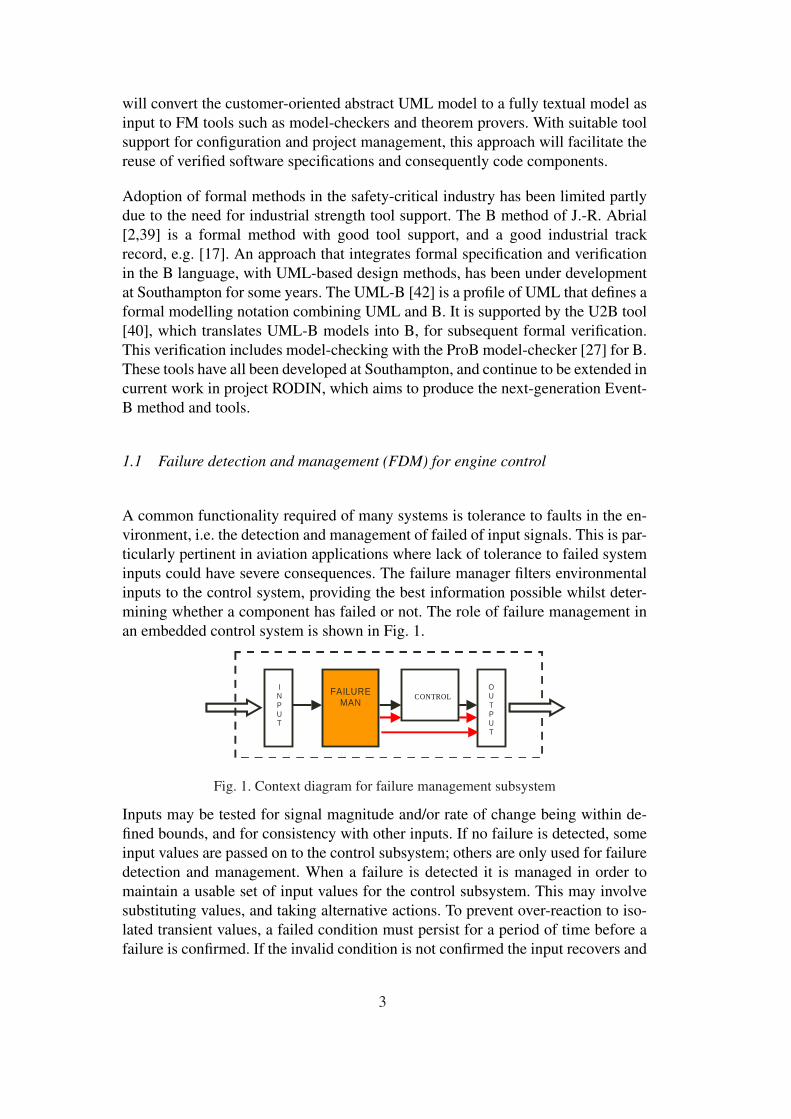
A common functionality required of many systems is tolerance to faults in the en-vironment, i.e. the detection and management of failed of input signals. This is par-ticularly pertinent in aviation applications where lack of tolerance to failed systeminputs could have severe consequences. The failure manager filters environmentalinputs to the control system, providing the best information possible whilst deter-mining whether a component has failed or not. The role of failure management inan embedded control system is shown in Fig. 1.
FAILURE
MAN CONTROL
INP
O U T P U T
I N P U T
Fig. 1. Context diagram for failure management subsystem
Inputs may be tested for signal magnitude and/or rate of change being within de-fined bounds, and for consistency with other inputs. If no failure is detected, someinput values are passed on to the control subsystem; others are only used for failuredetection and management. When a failure is detected it is managed in order tomaintain a usable set of input values for the control subsystem. This may involvesubstituting values, and taking alternative actions. To prevent over-reaction to iso-lated transient values, a failed condition must persist for a period of time before afailure is confirmed. If the invalid condition is not confirmed the input recovers and
3

is used again. Temporary remedial actions, such as relying on the last good value,or suppressing control behaviour, may be taken while a failure is being confirmed.Once a failure is confirmed, more permanent actions are taken such as switchingto an alternative source, altering or degrading the method of control, engaging abackup system or freezing the controlled equipment.
1.2 Contribution
Failure detection and management (FDM) in engine control systems is a demand-ing application domain, see e.g. [10]. Based on work on a case study provided byAT Engine Controls, we propose a method for the engineering, validation and ver-ification of generic requirements for product-line purposes. The approach exploitsgenericity both within as well as between target system variants. Although product-line engineering has been applied in engine and flight control systems [25,19],we are not aware of any such work in the FDM domain. Using UML-B we de-fine generic classes of failure-detection test for sensors and variables in the systemenvironment, such as rate-of-change, limit, and multiple-redundant-sensor, whichare simply instantiated by parameter. Multiple instances of these classes occur inany given system. Failure confirmation is then a generic abstraction over these testclasses: it constitutes a configurable process of execution of specified tests over anumber of system cycles, that will determine whether a failure of the componentunder test has occurred.
A complicating factor is the instability of the FDM requirements domain, which isoften subject to late change. This is because the failure characteristics of dynamiccontrolled systems are usually dependent on interaction with the control systemsbeing developed and can only be fully determined via prototyping. Our generic re-quirements formulation accommodates this ongoing requirements change process.
Our approach contributes methodologically to product-line requirements engineer-ing in its integration of informal domain analysis with domain and application en-gineering that exploits both UML and Formal Methods technology. The applicationof product-line engineering to failure detection and management is also novel. Wehave exercised the first three stages of our proposed four-stage process model: (i)domain analysis developed a generic requirement specification document for a classof systems, (ii) domain engineering then validated the requirements, producing aformal generic model in UML-B for the product line, and (iii) application engineer-ing then verified an example instance system. The fourth stage of the method, theaddition and verification of behaviour to generic and instance models, is ongoingwork.
4

1.3 Structure of the paper
The paper proceeds as follows. Section 2 introduces formal specification and veri-fication in B, and our approach in Southampton. Section 3 gives an overview of ourmethod. Sections 4 - 5 discuss the domain analysis and engineering activities thatresult in a validated generic model. Section 6 discusses the application engineeringof an instantiated system variant to verify the instance model. Section 7 gives anindustrial user’s perspective on the usability and applicability of the method andtools. Finally section 8 concludes with a discussion of related and future work, andan evaluation of the method.
2 Formal specification and verification with B
The B language [2] of J.-R. Abrial is a wide-spectrum language supporting a fullformal development lifecycle from specification through refinement to program-ming. It is supported by full-lifecycle verification toolkits such as Atelier B [4],and has been instrumental in successful safety-critical system developments suchas signalling on the Paris Metro [17].
A B specification gives an abstract description of requirements, modelled in termsof system state and behaviour. Simply put, state is described in terms of sets andrelations on those sets, and behaviour in terms of changes to that state caused byinvocation of events or operations. An invariant clause captures required propertiesof the system that must hold at all times, defining the meaning of the data and theintegrity of its structure. The B verification tools [12] generate proof obligations(POs) that initialization and all operations maintain the invariant; this is called op-eration consistency. Automatic and interactive provers are part of the method; wedo not discuss them further here.
A refinement step involves the transformation of an early, abstract nondetermin-istic specification into a more concrete one 2 , by elaboration with more data andalgorithmic structure, thus reducing nondeterminism. Using the refinement relationbetween abstract and concrete models, proof obligations guarantee that the refine-ment correctly represents the behaviour of the abstract specification it refines.
2.1 The Southampton approach
At Southampton two tools have been developed to support formal system devel-opment in B: ProB and U2B. ProB [27] is a model checker that searches the full
2 The concrete specification in this context is often called the refinement.
5

abstract state machine model of a B specification for invariant violations, returningany counterexample found. The state model can be presented graphically. Modelchecking avoids the effort of proof debugging in early development activities, serv-ing as a preliminary validation of the specification before commencing proof. ProBfurthermore provides a limited form of temporal model-checking, and user-drivenanimation of behaviour. Its use is discussed further in sections 5 and 6.
The UML-B [42] is a profile of UML that defines a formal modelling notation.It has a mapping to, and is therefore suitable for translation into, the B language.UML-B consists of class diagrams with attached statecharts, and an integrated con-straint and action language called µB, based on B. UML-B is thus comparable tothe UML/OCL specification approach of USE [22,23]. The profile uses stereotypesto specialise the meaning of UML entities to enhance correspondence with B con-cepts. UML-B provides a diagrammatic, formal modelling notation based on UML.The popularity of the UML enables UML-B to overcome some of the barriers tothe acceptance of formal methods in industry. Its familiar diagrammatic notationsmake specifications accessible to domain experts who may not be familiar withformal notations. UML-B hides B’s infrastructure by packaging mathematical con-straints and action specifications in µB into small sections within the context ofan owning UML entity. The U2B [40] translator converts UML-B models into Bcomponents (abstract machines and their refinements), thus enabling B verificationand validation technology to be exploited.
3 Overview of method
We first give an overview of the method which is then discussed in more detail in thefollowing sections - see Fig. 2. The first stage is domain analysis (section 4) whichis based on prior experience of developing products for the application domainof failure detection and management in engine control. This domain analysis isguided by the experience of [25], who also worked in the engine control domain.Its purpose is twofold: (i) to “identify reusable artifacts in the domain”, and (ii)to define a taxonomy of generic requirements and produce a generic requirementsspecification document (RSD) [6] subject to that taxonomy 3 . A first-cut genericmodel in object-association terms, naming and relating these generic requirements,is constructed as part of the RSD.
The identification of a useful generic model is a difficult process and therefore fur-ther validation and development of the model is required. This is done in the domainengineering stage (section 5) where a more rigorous examination of the first-cutmodel is undertaken, using the B-method and the Southampton tools. This stagealso serves to structure “the reusable artifacts in such a way (sic) that facilitated
3 Experience [3] shows the value of this taxonomic approach to requirements specification.
6

reuse during the development of new applications” [25]. The model is animated bycreating typical instances of its generic requirement entities, to test when it is andis not consistent. This stage is model validation by animation, using the ProB andU2B tools, to show that it is capable of holding the kind of information that is foundin the application domain. During this stage the relationships between the entitiesare likely to be adjusted as a better understanding of the domain is developed. Thisstage results in a validated generic model of requirements that can be instantiatedfor each new application.
domain analysis domain engineering
first-cut generic model
validated generic model
previous product experience
Fig. 2. Process for obtaining the generic model
For each new application instance, the requirements are expressed as instancesof the relevant generic requirement objects and their associations, in an instancemodel - see Fig. 3. The ProB model checker is then used to verify that the applica-tion is consistent with the relationship constraints embodied in the generic model.This instance, or application engineering stage, producing a verified consistent in-stance model, shows that the requirements are a consistent set of requirements forthe domain. It does not, however, show that they are the right (desired) set of re-quirements, in terms of system behaviour that will result.
The final stage, therefore, is to add dynamic features to the instantiated model inthe form of variables and operations that model the behaviour of the entities in thedomain and to animate this behaviour so that the instantiated requirements can bevalidated. This final stage of the process - “validate instantiation” in Fig. 3 - is workin progress.
instantiate generic model
verify instantiation
validated generic model
application instance requirements
instance model
consistent instance model
validate instantiation
validated instance model
Fig. 3. Process for using the generic model in a specific application
Each method stage will be followed by an instance of a stage template. This willsummarize and structure the stage by briefly identifying its approach, parametersand V & V activities, as well as stage inputs and outputs:
Inputs: Documents, information, people consulted as input to this stageApproach: Techniques or procedures appliedParameters: Any data specific to this stage
7

Outputs: Documents and results produced by this stageV & V: Validation/ verification activities applied during this stage
4 Domain analysis
The strategy adopted to reach the first-cut generic requirement model (Fig. 2) wasto apply domain analysis in a style similar to that used by Lam [25]. Prieto-Diaz[37] defines domain analysis as “a process by which information used in developingsoftware systems is identified, captured and organised with the purpose of makingit reusable when creating new systems”. He identifies three activities which arecentral to our domain analysis:
(1) identification of reusable entities(2) abstraction or generalization(3) classification and cataloging for further reuse
The first step was to define the scope of the domain in discussion with the enginecontroller experts. This was done by considering legacy specification documentsof a small number of representative failure management engine systems, resultingin a brief scoping definition of the FMS. This definition forms an early part of therequirements specification document (RSD) produced by this project and is givenin table 1.Table 1FMS scoping requirements
PROC1 The subsystem executes on a given process cycle.
DET1 The subsystem detects abnormal conditions of inputs caused by failures of the external equipment.
OUT1 Inputs that are found to be in a normal condition may be passed on as outputs (if they are requiredby other subsystems).
CONF1 When an abnormal condition is detected, the subsystem confirms the suspected failure over aperiod of time. During this time the condition may recover.
ACT1 The subsystem takes some temporary action to simulate acceptable input while a suspected faultis being confirmed.
ACT2 The subsystem simulates acceptable input conditions or performs other permanent failure actionsif it confirms an abnormal condition of the inputs.
PROC2 All tests will be implemented by configuring the generic requirements specified in this documentto meet the specific requirements of the application (as shown in ...).
Identification of commonalities (reusable entities) by abstraction: Legacy doc-uments were used, with expert consultation, to identify specific requirements thatmight reveal more abstractly defined requirements generic across airframes. Thatis, specific examples were sought of logical groups of airframe instance require-ments, where a group aggregated similar requirements from various system in-stances. Each group was then used to identify a higher-level commonality, by aprocess of abstraction. Table 2 shows three of these specific requirement/ com-monality pairs, giving just one of the instance requirements that resulted in the
8

associated commonality.
Table 2Sample instance requirements revealing commonalities
(1) Engine speed ES Each ES sensor ESa, ESb has one upper bound and two lower bounds for range check-ing. The upper bound test is valid at all times. Lower bound test 1 (starting) is validif input condition START MODE and LIGHT OFF and not START ABORT. Lowerbound test 2 (running) is valid if input condition RUN MODE and not START MODE.
An INPut is subject to a number of tests; each such test is subject to a CONDition (overINPuts, in this case).
(2) Engine torque EQ EQ has a lower bound test valid if output condition ES > 80%. This test is subject to along fault count 2 - 1 - 32. That is, each fault adds +2, each non-fault adds -1 to a faultcount subject to 0 = pass, 32 = fail.
A test is subject to a CONDition over an OUTput; each such test is subject to a DETec-tion and a CONFirmation fault count.
(3) Engine speed ES Output engine speed cES is set to ESa only when all 3 magnitude DETections, 1 differ-ence DETection, and one rate DETection are passed.
An OUTput is set by an ACTion, where that ACTion results from a successful test.
This analysis quickly revealed a high degree of genericity in the static configurationof the system: a small number of key system entities were quickly revealed in afixed relation to each other. In table 2 (1), the engine speed sensor is an INPutentity subject to a number of tests or DETections. A DETection is a predicate thatcompares the value of an expression involving the input to a limit value, e.g. arange check. Each test is invoked subject to a defined CONDition - a predicatebased on the values and/or failure states of other INPut sensors. In (2) we see thata test consitutes both a DETection and a CONFirmation, that is the applicationof an iterative algorithm to confirm, over a number of sampling cycles, whetheran input’s failed status is transient or permanent. The configuration of a specificsystem instance will be defined by an instantiation of these entities with instancesensor fits, detection parameters etc.
Generic requirements specification: In the emerging RODIN method for Event-B [31] Abrial recommends labelling requirements in the RSD taxonomically; inour case the taxonomy emerged naturally from the generic entities revealed by theabstraction process above:
INP Input to be tested.COND Condition under which a test is performed. A predicate over INP and OUT
values.DET Detection of a failure state. A predicate that compares the value of an expres-
sion involving the input to a limit value.CONF Confirmation of a (persistent) failure state.ACT Action taken either normally or in response to a failures, possibly subject to
a condition. Assigns the value of an expression, which may involve inputs and/orother output values, to an output.
OUT Output signal to be used in an action
9

Elaboration of relationships: The analysis then elaborated the entity relationships.This was used to form the first-cut generic model of Fig. 2, which is elaborated inUML in Fig. 4. An input (INP) instance represents a sensor value input from theenvironment. It may have many associated tests, and a test may utilise many otherinputs. A TEST is composed of a detection method (DET) and confirmation mech-anism (CONF) pair 4 . For example an engine speed input, which is tested for outof range magnitude as well as excessive rate of change, has a detection and asso-ciated confirmation for the magnitude test and a different detection and differentconfirmation for the rate of change test. Each test also has a collection of condi-tions (COND) that must be satisfied for the test to be applied. For example, theengine speed magnitude test that is applied when the engine is running is differentfrom the engine speed magnitude test applied while starting the engine. A con-firmation mechanism is associated with three different sets of actions (ACT), thehealthy actions (hAct), the temporary actions (tAct), taken while a test is con-firming failure, and the permanent actions (pAct), taken when a test has confirmedfailure. Each action is associated with at least one output (OUT) that it modifies.
DET
INPtest 0..*0..*COND0..* 1
CONF
111 1
ACT
0..*
1
0..*
1
0..*1
OUT
1..*
1..*
+out
+act
1..*
1..*
0..*0..*
+input+cond
10..*
1
1
1
+hAct
+tAct
+pAct
0..*
0..*
0..*
Fig. 4. Overview of common types of elements of functionality and their interrelationships
The detection mechanism DET of a test can be further decomposed as (i) a check(DET MAG) that signal magnitude is within defined bounds, (ii) a check (DET RATE)that signal rate of change is within defined bounds or (iii) a comparison (DET PRED)with a predicted value.
Requirements specification document (RSD): The generic requirements wererecorded into a traceable requirements specification document [6] for the case study.The document had several features which assisted in presenting the requirementsin a way suitable for further analysis, in particular a generic section and an exam-ple instantiation of it in tabular form. Note that every system instance will requirespecification in such a tabular form.
The generic section of the RSD includes
(1) The taxonomy of requirements.(2) The model (Fig.4) of the generic requirement domain.
4 Consequently TEST is not a category in the requirements taxonomy above.
10

(3) For each labelled generic requirement, a concise statement of the requirementand an explanation of the rationale behind it.
Table 3 gives some examples of the resulting generic requirements from the RSD.
Table 3Sample generic requirements
INP2 The subsystem uses input variables which contain either digitized values or Boolean states.
DET MAG1 Compares input value against a magnitude (range) limit. The input is in error if the limit is ex-ceeded.
DET PRED1 Compare input value against a computed value. The input is in error if the discrepancy lies outsidea tolerance of this value.
DET CONF1 Every detection is subject to precisely one confirmation; every confirmation acts on precisely onedetection.
DET COND1 Every detection may act subject to a number of conditions
CONF4 (persistence counter failure mechanism) If a test has detected an error (failure) on an input then...(algorithm)
The example instantiation section is in tabular form and consists of uniquely iden-tified instances of the elements in the generic model, and references from eachinstance to other instances as described by the relationships in the generic model.Table 4 gives two instances from each of DET MAG and CONF data tables:
Table 4Sample instance requirements
Ref. value name dir limit freq condition confirm
tested ms
MAG1.21 INP2.10 ESa lo 45 24 COND5.3 CONF4.1
MAG1.22 INP2.11 Esb up 130 24 COND1 CONF4.1
Ref. name x inc y dec z limit description
CONF4.1 fault count 2-1-8 2 1 8 fault counter with
bias to confirm
CONF4.5 fault count 2-1-32 2 1 32 biased fault counter,
16 to confirm
Key issues and rationale for requirements: Concurrently with the above activity,we established key issues, or high-level requirements goals. Key issues were iden-tified which served as “higher-level” properties required of the system. An exampleof such a key property would be that the failure management system must not beheld in a transient action state indefinitely. Considering the requirements’ rationaleis useful in reasoning about requirements in the domain [25]. The rationale fromwhich the above property has been derived, is that a transient state is temporary andactions associated with this state may only be valid for a limited time. Table 5 givessome further examples.
Reflection: This analysis showed that failure management systems are charac-terised by a high degree of fairly simple similar units made complex by a large
11

Table 5Key issues and rationale
(1) Detect failures Outsource environment failure detection/ sanitization fromcontrol system to FMS. Detect possible failures in input sig-nals from airframe with maximum sensitivity, ie maximumtrue positives.
(2) Confirm failure before perma-nent action is taken
Tolerate noise in the input signals: transient signal deviationswill be tolerated with maximum specificity, i.e. maximum truenegatives.
(3) Take action appropriately Once a failure has been detected some action to cater for thefailure must be taken. The most appropriate action may dependon the conditions of other inputs and outputs.
(4) Apply tests under appropriateconditions
Some tests are only valid under certain conditions of other in-puts and outputs and could otherwise result in false positives.
number of minor variations and interdependencies. The domain presents opportu-nities for a high degree of reuse within a single product as well as between products.For example, a magnitude test type is usually required in a number of instances ina particular system. This is in contrast to the engine start domain addressed byLam [25], where a single instance of each reusable function exists in a particularproduct. The method described in this paper is targeted at domains such as failuremanagement where a few simple units are reused many times and a particular con-figuration depends on the relationships between the instances of these simple units.We will return to the applicability of the method in conclusion in section 8.
Domain analysis - stage template:
Inputs: Engine controller experts. Legacy specification documents of representa-tive failure management engine systems
Approach: Identification of commonalities by abstraction. Elaboration of relation-ships. Generic requirements specification. Identification of requirements’ key is-sues and rationales
Parameters: UML class modelling. Abrial’s taxonomic approach to requirementsspecification
Outputs: Generic requirements specification document (RSD) including first-cutUML model
V & V: Informal peer review
5 Domain Engineering
The aim of the domain engineering stage is to validate the first-cut generic model ofthe requirements, thus deriving a validated generic requirements model as per Fig.2. At input to the domain engineering stage this is essentially a pure UML classmodel (Fig. 4) without any dynamic features. The first task is conversion of thismodel to UML-B (Fig. 5), to enable automatic generation of the B model. The mainwork of this stage is the considered validation and derivation of the output model
12
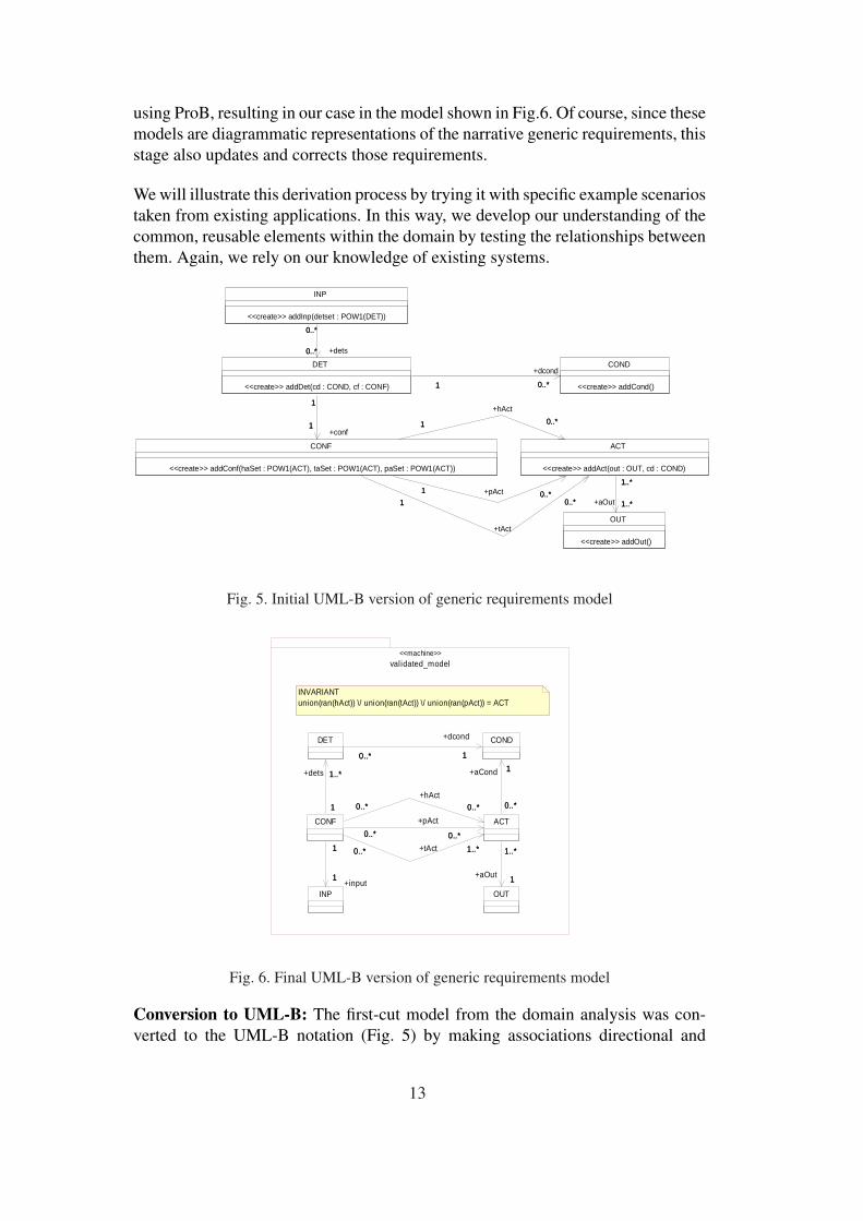
using ProB, resulting in our case in the model shown in Fig.6. Of course, since thesemodels are diagrammatic representations of the narrative generic requirements, thisstage also updates and corrects those requirements.
We will illustrate this derivation process by trying it with specific example scenariostaken from existing applications. In this way, we develop our understanding of thecommon, reusable elements within the domain by testing the relationships betweenthem. Again, we rely on our knowledge of existing systems.
INP
<<create>> addInp(detset : POW1(DET))
CONF
<<create>> addConf(haSet : POW1(ACT), taSet : POW1(ACT), paSet : POW1(ACT))
OUT
<<create>> addOut()
ACT
<<create>> addAct(out : OUT, cd : COND)
0..*1
+tAct
0..*10..*1 +pAct 0..*1
0..*1
+hAct
0..*1
1..*
1..*
+aOut 1..*
1..*
DET
<<create>> addDet(cd : COND, cf : CONF)
0..*
0..*
0..*
+dets0..*
1
1
+conf1
1
COND
<<create>> addCond()0..*1
+dcond
0..*1
Fig. 5. Initial UML-B version of generic requirements model
OUT
CONDDET
10..*
+dcond
10..*
ACT
1
1..*
+aOut 1
1..*
1
0..*
+aCond 1
0..*
INP
CONF
1
1..*
1
+dets 1..*
1..*0..* +tAct 1..*0..*
0..*0..*
+pAct
0..*0..*
0..*0..*+hAct
0..*0..*
1
1
+input1
1
validated_model<<machine>>
INVARIANTunion(ran(hAct)) \/ union(ran(tAct)) \/ union(ran(pAct)) = ACT
Fig. 6. Final UML-B version of generic requirements model
Conversion to UML-B: The first-cut model from the domain analysis was con-verted to the UML-B notation (Fig. 5) by making associations directional and
13

adding stereotypes and UML-B clauses (tagged values) as defined in the UML-B profile [42]. U2B does not support association classes in a suitable form for thefollowing validation. Therefore, before starting we removed the association classTEST. Instead we (i) mapped association dcond from class DET to class COND,(ii) removed association input, and (iii) mapped association dets from INP toDET.
Conversion to B: This model conversion allows the U2B translator tool to convertthe model into the B notation where validation and verification tools are available.The translation automatically expresses the constraints of the UML-B model asan invariant property. This defines the multiplicity constraints of each association,and the class membership of instances. The final B machine corresponding to theoutput model of this stage (Fig.6) is shown in Fig. 7. Note that this domain engi-neered model really represents a metamodel for any well-defined instance system.The B version allows us to “populate” the metamodel with sample instance data,and check its validity. In Fig. 7 the VARIABLES represent the UML-B classes ascontainer sets for the sample instance data being validated, whilst the INVARIANTcarries the metamodel constraint information that the VARIABLES must adhere to.
The first eight invariant conjuncts define the associations as functions between theclasses. In some cases the functions are further constrained due to the multiplic-ities on the associations. Two examples are (i) a total bijection invariant (>>->)generated by U2B to reflect the 1 to 1 multiplicity constraints of the associationinput from CONF to INP, and (ii) the surjectivity (-->>) of association aOut.In some cases extra conjuncts are needed as in the case of dets, which must mapto disjoint sets of instances that completely cover the instances of the class DETdue to the multiplicity, 1, at the source end of the association. The last conjunctin Fig. 7 reflects an additional, textual constraint that we added during the domainengineering stage to ensure that all instances of the class ACT are used by one ofthe association roles that emanate from the class CONF.
Validation by instantiation: To validate the first-cut model we needed to be ableto build up the instances it holds in steps 5 . For this task, all classes were givenvariable cardinality (there is a UML-B clause to define the cardinality and variabil-ity of classes) and a constructor was added to each class so that the model could bepopulated with instances. The constructor was endowed with behaviour (written inµB) to set any associations belonging to that class to values (i.e. instances of otherclasses) supplied as parameters.
The developing model was then tested by adding “dummy” instances using the an-imation facility of ProB and examining the values of the B variables representingthe classes and associations in the model to see that they developed as expected. Ini-
5 Note that model Fig. 6 is the result of this domain engineering process, and reflects afixed configuration of DET, CONF etc. elements. Thus the constructors used here are partof this validation process only, and not part of the final system.
14

MACHINE validated_modelDEFINITIONS
disjoint(ff)==!(a1,a2).( a1:dom(ff) & a2:dom(ff) & a1/=a2 =>ff(a1)/\ff(a2)={} ) ;
SETSINP; DET; CONF; COND; ACT; OUT
VARIABLESdcond, input, dets, tAct, pAct, hAct, aOut, aCond
INVARIANTdcond : DET --> COND &input : CONF >->> INP &dets : CONF --> POW1(DET) &tAct : CONF --> POW1(ACT) &pAct : CONF --> POW(ACT) &hAct : CONF --> POW(ACT) &aOut : ACT -->> OUT &aCond : ACT --> COND &disjoint(dets) &union(ran(dets)) = DET &union(ran(hAct)) \/ union(ran(tAct)) \/ union(ran(pAct)) = ACT
END
Fig. 7. B Machine
tially, an instance of CONF cannot be added because there are no instances of INPwith which to parameterize it. This forces a partial ordering on the population ofthe model. The INP constructor is available initially because the INP class has nooutgoing associations. As soon as an instance of INP is added the multiplicity con-straint of the association, input, is violated. ProB provides an indicator to showwhen the invariant is violated. Observing the invariant violations is an essentialpart of the validation of the model. Knowing that the model will detect inconsistentinstantiations is at least as important as knowing that it accepts consistent ones.
ProB and an example animation: Figure 8 shows ProB being used to validatethe final version of the generic model. The top pane shows the B version of themodel generated automatically from the UML-B version (Fig. 6). The centre bot-tom pane shows the currently available operations (i.e. the constructors we addedto the generic model for testing purposes). An operation is only enabled when itspreconditions and guards are true. In our model this is when there are unused ‘pos-sible’ instances left to create and values available to supply as parameters. (Notethat, for practical reasons, we limit a class’s set of possible instances to a smallenumerated set during this stage). An available operation is invoked by selectingit from this pane. Each available operation is repeated in the list for each possibleexternal (parameter) or internal (non-determinism) choice. The left pane shows thecurrent value of each variable as well as an indication of whether the invariant hasbeen violated. The right pane shows the history, i.e. sequence of operations thathave already been taken.
We run through the animation shown in Fig. 8:
(1) Initially only the constructors for INP, OUT and COND are available becausethese classes have no outgoing associations.
(2) An instance o1 of OUT was constructed first as shown at the bottom of the
15
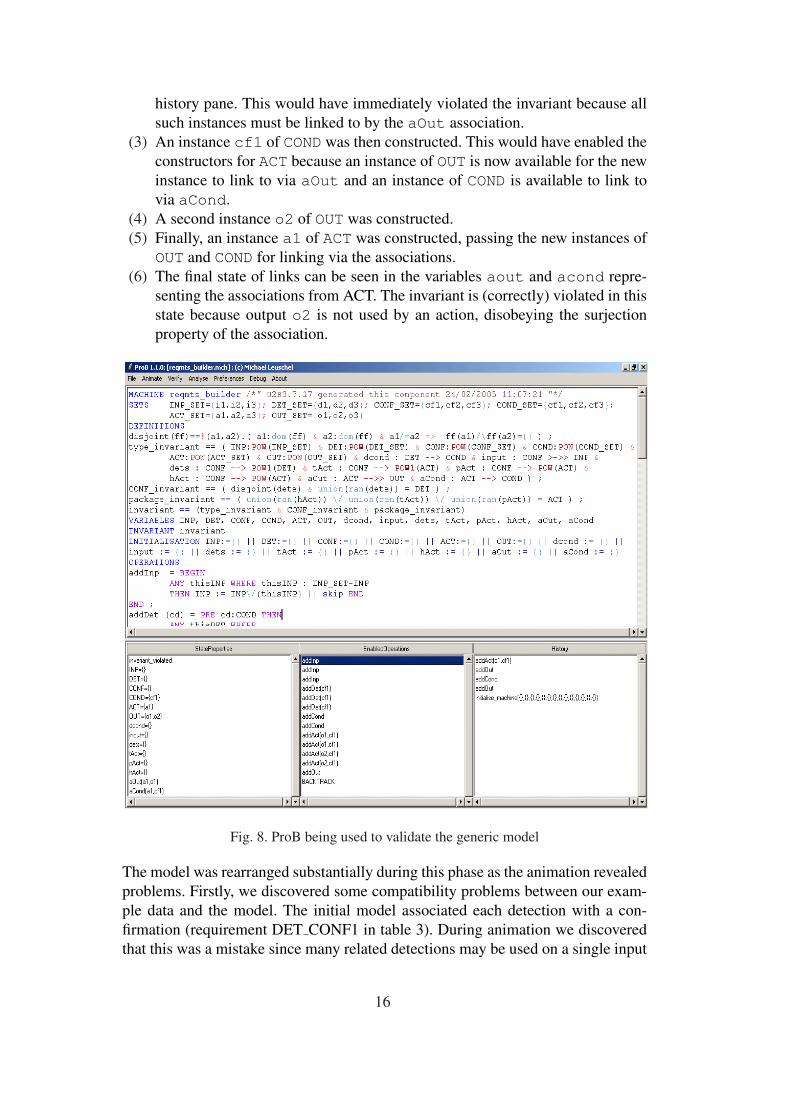
history pane. This would have immediately violated the invariant because allsuch instances must be linked to by the aOut association.
(3) An instance cf1 of COND was then constructed. This would have enabled theconstructors for ACT because an instance of OUT is now available for the newinstance to link to via aOut and an instance of COND is available to link tovia aCond.
(4) A second instance o2 of OUT was constructed.(5) Finally, an instance a1 of ACT was constructed, passing the new instances of
OUT and COND for linking via the associations.(6) The final state of links can be seen in the variables aout and acond repre-
senting the associations from ACT. The invariant is (correctly) violated in thisstate because output o2 is not used by an action, disobeying the surjectionproperty of the association.
Fig. 8. ProB being used to validate the generic model
The model was rearranged substantially during this phase as the animation revealedproblems. Firstly, we discovered some compatibility problems between our exam-ple data and the model. The initial model associated each detection with a con-firmation (requirement DET CONF1 in table 3). During animation we discoveredthat this was a mistake since many related detections may be used on a single input
16
all of which should have the same confirmation mechanism. We changed the detsassociation to 1 CONF to 1-to-many DETs, with the disjointness condition men-tioned before. This change had to be reflected in a change to the underlying genericrequirement DET CONF1.
The model was rearranged to associate inputs with confirmations. We also discov-ered that actions were often conditional, so we added an association from ACT toCOND. Apart from these compatibility issues we discovered several changes to themultiplicities of associations. For example, since we had associated sets of actionswith confirmations, we did not need a further multiplicity from actions to outputs,thus simplifying the model a little. The most significant change concerned the threeassociations from CONF to ACT where we required each instance of ACT to be usedin at least one of the three associations. Since this is not expressible as a simple mul-tiplicity, a µB invariant was added to the class diagram as an annotation (see Figs.6, 7). As for DET CONF1 above, this validation resulted in further amendments tothe narrative generic requirements.
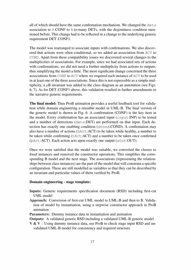
The final model: Thus ProB animation provides a useful feedback tool for valida-tion while domain engineering a reusable model in UML-B. The final version ofthe generic model is shown in Fig. 6. A confirmation (CONF) is the key item inthe model. Every confirmation has an associated input (input:INP) to be testedand a number of detections (dets:DET) are performed on that input. Each de-tection has exactly one enabling condition (dcond:COND). A confirmation mayalso have a number of actions (hAct:ACT) to be taken while healthy, a number tobe taken while confirming (tAct:ACT) and a number to be taken once confirmed(pAct:ACT). Each action acts upon exactly one output (aOut:OUT).
Once we were satisfied that the model was suitable, we converted the classes tofixed instances and removed the constructor operations. This simplifies the corre-sponding B model and the next stage. The associations (representing the relation-ships between class instances) are the part of the model that will constrain a specificconfiguration. These are still modelled as variables so that they can be described byan invariant and particular values of them verified by ProB.
Domain engineering - stage template:
Inputs: Generic requirements specification document (RSD) including first-cutUML model
Approach: Conversion of first-cut UML model to UML-B and then to B. Valida-tion of model by instantiation, using a stepwise constructor approach in ProBanimation
Parameters: Dummy instance data in instantiation and animationOutputs: A validated generic RSD including a validated UML-B generic modelV & V : Using dummy instance data, use ProB to check stage input RSD and un-
validated UML-B model for consistency and required structure
17

6 Application engineering
Having arrived at a useful generic model for a product range, the model can beput to use by verifying that a particular configuration, or instantiation of the modelsatisfies its constraints. To illustrate and test this stage we constructed an exam-ple instance of a failure management specification for an engine controller, basedon existing AT Engine Controls products. This stage represents the verificationas per Fig. 3 of a system instance against the classes, associations and invariantsof the generic model. The resulting output is a consistent instance model. Notethat this method is not limited only to failure management systems; such a genericmodel and corresponding instances can be developed for any domain where a class-association style of modelling is applicable and the instantiation is of static con-figuration data. We return to the question of the generality of the method in theconclusion, section 8.
Instance specification and incorporation in model: This verification is a similarprocess to the domain engineering validation, but the focus is on finding and cor-recting errors in the instance data rather than in the model. The example instancespecification was first described in tabular form (see Fig. 10), mimicing the form oftable 4 in the RSD. Each class is represented by a separate table with properties foreach entry in the table representing the associations owned by that class. To verifyits consistency, the tabular form was translated into class instance enumerations andassociation initialization clauses attached to the UML-B class model. This one-shotinitialization process in UML-B is in contrast to the stepwise instance-constructorprocess of the previous stage. Initially, table translation to UML-B was done man-ually, which was tedious and error prone.
Verification with ProB: ProB was then used to check which conjuncts of the in-variant were violated by the example instantiation. The invariant is a predicate thatexpresses all the constraints of the generic model: instances belong to classes, asso-ciation links satisfy the multiplicity constraints of their associations and any furtherannotated invariant predicates that may involve several associations. To check theinvariant is satisfied by the instance mode, all that is needed is to invoke the initial-ization in ProB. Fig. 9 shows the “analyse invariant” facility of ProB being used toidentify an error (each line represents a conjunct in the invariant from Fig. 7). Sev-eral conjuncts are violated (=false); all are constraints on associations involvingthe class, ACT. For example, the second of these (aOut) states that every ACTmustbe associated with exactly one OUT, and that every OUT must be associated withone or more ACTs 6 . Examining the initializations of these associations reveals thatlinks had not been added for action act1310. Several iterations were necessaryto eliminate errors in the tables before the invariant was satisfied (all conjuncts =
6 This is what is meant by “−− >>” in B in Fig. 7, and by “TotalSurjection” in ProB inFig. 9.
18

true).
Fig. 9. ProB being used to verify the example application
We found that the analyse invariant facility provided some indication of where theinvariant was violated (i.e. which conjunct) but, in a data intensive model such asours, it is still not easy to see which part of the data is at fault. In the exampleabove, any ACT without initialized associations would cause the aOut conjunctto go false. In general there are many data instances of a given class. What isrequired from such tool-supported verification is the automated production of adata counterexample to the conjunct.
6.1 Requirements Manager(RM): A tool for instance data management
To address the problems found with using ProB to verify instantiation data, wedeveloped a tool that interfaces with the UML drawing tool to automate manage-ment and verification of instance configuration data. The tool was developed as anEclipse plug-in by a student group 7 . The tool provides an extension to the Ratio-nal Software Architect UML modelling tool (which is also based on Eclipse). Menuextensions are provided to operate the tool from the class diagram of the genericmodel, so that a database repository can be generated based on the classes and theirassociations. Instance specification data, in the form of class instances and associa-tion links, can then be ‘bulk uploaded’ directly from Excel configuration files suchas Fig. 10. This avoids the tedious and error prone process of manually populating
7 Please see acknowledgments.
19
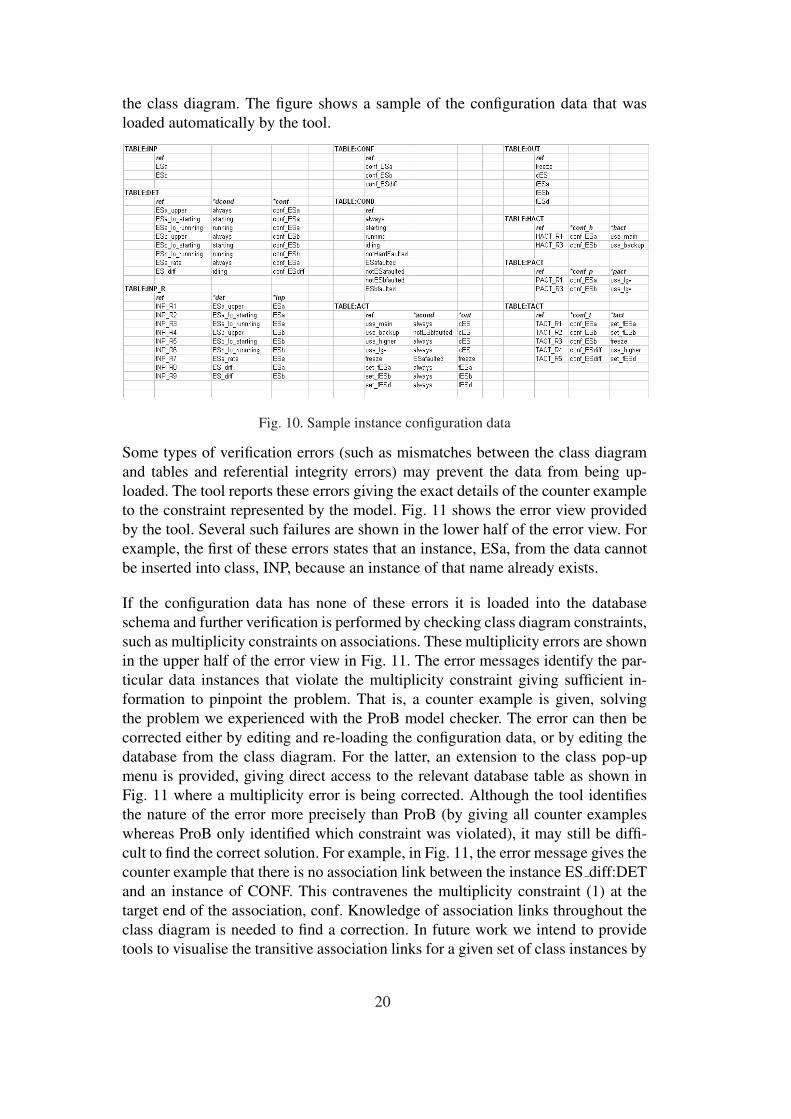
the class diagram. The figure shows a sample of the configuration data that wasloaded automatically by the tool.
Fig. 10. Sample instance configuration data
Some types of verification errors (such as mismatches between the class diagramand tables and referential integrity errors) may prevent the data from being up-loaded. The tool reports these errors giving the exact details of the counter exampleto the constraint represented by the model. Fig. 11 shows the error view providedby the tool. Several such failures are shown in the lower half of the error view. Forexample, the first of these errors states that an instance, ESa, from the data cannotbe inserted into class, INP, because an instance of that name already exists.
If the configuration data has none of these errors it is loaded into the databaseschema and further verification is performed by checking class diagram constraints,such as multiplicity constraints on associations. These multiplicity errors are shownin the upper half of the error view in Fig. 11. The error messages identify the par-ticular data instances that violate the multiplicity constraint giving sufficient in-formation to pinpoint the problem. That is, a counter example is given, solvingthe problem we experienced with the ProB model checker. The error can then becorrected either by editing and re-loading the configuration data, or by editing thedatabase from the class diagram. For the latter, an extension to the class pop-upmenu is provided, giving direct access to the relevant database table as shown inFig. 11 where a multiplicity error is being corrected. Although the tool identifiesthe nature of the error more precisely than ProB (by giving all counter exampleswhereas ProB only identified which constraint was violated), it may still be diffi-cult to find the correct solution. For example, in Fig. 11, the error message gives thecounter example that there is no association link between the instance ES diff:DETand an instance of CONF. This contravenes the multiplicity constraint (1) at thetarget end of the association, conf. Knowledge of association links throughout theclass diagram is needed to find a correction. In future work we intend to providetools to visualise the transitive association links for a given set of class instances by
20

Fig. 11. Tool screenshot with error view and update window
automatically generating object diagrams from the database.
The ability to modify data via the class diagram enables individual class instancesand association links to be added to an existing (or developing) configuration. Therequirements engineer can invoke the Requirements Manager(RM) tool at selectedpoints (when the data is expected to be in a consistent state) to check the configu-ration satisfies the generic constraints of such systems. A limitation of the databaseapproach to managing configuration data is that many to many association relationscan not be represented in database schema. In order to represent many to many as-sociations we had to add intermediate linking classes (see INP R inserted betweenINP and DET and HACT, PACT and TACT between CONF and ACT). In futureversions of the tool we intend to hide this representation mismatch from the user.
The RM tool has been developed as an Eclipse plug-in to integrate with the RODINproject toolset including the UML-B drawing tool, U2B translator, ProB, B proverand B database. In parallel with the development of RM, the U2B tool has been re-developed in Eclipse to accept input models based on the UML2 metamodel (uponwhich RSA models are based). A UML2 profile has been developed to extend theUML notation and provide relevant property fields to accept information such asthe configuration data. Once the configuration data has been successfully verifiedRM can be used to populate the UML-B stereotype properties. This utilises the in-stances property attached to classes and the value property attached to associations.These values are utilised by U2B when it produces a B version of the model. Fig.
21

12 shows the stereotype property value for an association after population by RM.
Fig. 12. Tool screenshot with properties view
Fig. 13 8 illustrates the process of using the RM tool 9 . Once a class diagram hasbeen loaded (loadCD), the database schema can be generated (generateDBS).If this fails, for example if the class diagram contains elements that are not sup-ported, a new class diagram must be loaded (or the current one modified). If itsucceeds, the state DBSGenerated has an invariant dbs is correct repre-senting that a valid schema is available for the class diagram. From this state datacan be bulk loaded, loadDT, which may fail due to referential integrity problemsor succeed and enter the state DTLoaded. The invariant, dt preverifies, forthis state, represents that data has no such errors. The data can now be checked(checkDT) for other errors, such as multiplicity constraint violations. If there areno such errors (dt verifies) the data can be used to populate the class diagram(generateOBS). At any time, if the class diagram is modified (loadCD), theschema must be regenerated and new data loaded.
Application engineering - stage template:
Inputs: Validated generic requirements specification document (RSD) includingvalidated UML-B model
Approach: Verification of instance data by one-shot initialization in ProB. Re-quirements Manager tool for system instance specification repository and verifi-cation, with data counterexamples
Parameters: Sample instance data from sample instance system tables in RSDOutputs: A verified system instance modelV & V : Verification on instance data against validated generic model using ProB
8 The symbol ¬ means logical negation.9 This statechart corresponds to a partial B model of the RM tool, which has been fullymodel-checked in ProB.
22

CDLoaded
¬ DBSGenerated
DBSGenerated
¬ DTLoaded
DTLoaded
¬ OBSGenerated
OBSGenerated
generateOBS [dt_verifies]/ m:=obsgen_success
checkDT [dt_verifies]/ m:=dtver_success
checkDT [¬ dt_verifies]/ m:=dtver_failed
generateDBS [dbs_is_correct ]/ m:=dbsgen_success
loadDT(dt) [dt_preverifies]/m:=dtprever_success
loadDT(dt) [¬ dt_preverifies]/m:=dtprever_failed
generateDBS [¬ dbs_is_correct]/ m:=dbsgen_failed
INV: dbs_is_correct
INV: dt_preverifies
INV: dt_verifies
Start
loadCD(cd)
loadCD(cd)
¬ CDLoaded
Created with Poseidon for UML Community Edition. Not for Commercial Use.
Fig. 13. Statechart for RM tool
7 Industrial User View
The techniques described in this paper include several areas which will be of inter-est to industry.
• The identification and formal validation of a generic requirement model for agiven problem domain.
• A technique to formalize UML and benefit from formal validation and verifica-tion tools and methodologies
• A technique to automatically verify the instantiation of a generic model withrealistic large scale data appropriate for product line engineering.
The class of problems targeted by our method have a relatively simple architec-tural structure of common functions but a complex pre-determined instantiationof these functions. With such problems, the identification of the underlying com-mon functional architecture is crucial to identify generic requirements and makethe problem manageable. Our industrial partner, ATEC, had no prior experiencewith formal specification techniques but with support and guidance was able toperform the modelling and use the associated tools. The next stage, adding be-havioural details, would entail textual specification of operation guards and actionsrequiring more extensive understanding of µB. Work is underway in the RODINproject to improve the accessibility of UML-B by increasing integration with the
23

underlying B toolset. The animation facility of the ProB tool is particularly use-ful to demonstrate behaviour to the domain user and, as used here, did not requireknowledge of B to understand it. However it is envisaged that to demonstrate thebehavoural development of the model the animation may need to be supported bymodel documentation and an industrial strength GUI to provide a domain expert aclearer understanding of the model when executing scenarios. With support fromthe instantiation database tools the technique contributes towards product line de-velopment through its ease of instantiating realistic scale of requirements data.
8 Conclusion and related work
8.1 Related work in context
Parnas’ prescient early work [35] characterized three types of approach to the de-velopment of software product lines, or “program families” - (i) syntactic modifica-tion, (ii) modular specification, and (iii) refinement. At that time, type (i) involvedthe development of a complete program, followed by the production of variants bymodifying the original program. Since then this type of approach has been elabo-rated through process phases e.g. requirements, architecture, and through the struc-turing of artefacts of those phases. Type (ii) has grown into today’s component-based software engineering (CBSE) approaches such as [16,18,43]. All types ofapproach involve a domain engineering activity that captures the requirements thatall family instances must share - the commonalities - and the requirements thatvary between instances - the variabilities [14] - into a generic, reusable softwareresource. This is followed by an application engineering activity that uses this re-source to generate the specific instance systems as necessary. Most product linework assumes an early domain analysis activity, e.g. [37], for gathering and struc-turing all relevant information from the application domain to support the develop-ment of such a generic, reusable software resource.
It is noteworthy that the Parnas’ approach type (i) remains dominant today, e.g.[36,19,26,25]. In this type of approach, application engineering deploys an in-stance derivation process against generic models/architectures and specific compo-nents/interfaces and variation points, to generate an instance system: an elaborateprocess of syntactic modification. In [36] an “Orthogonal Variability Model” mod-els variabilities, their constraints and variation points as first-class citizens, sepa-rately from the generic architecture of commonalities. The maturity of the compo-nent model in the picture may merge Parnas’ approach type (i) into type (ii).
Some logic-based and formal methods techniques have been proposed for soft-ware product lines. Validation of logically-defined requirements and constraints onthe variabilities (e.g. var1(i) ⇒ var2(i) ∧ ¬var3(i) for instance i) can be per-
24

formed [30]. Feature models defined with differing degrees of genericity, bindinginto the software construction process at different points, can be validated similarly[46]. Formal models also allow formal verification to happen, e.g. feature model-checking [46] and product line architectural model-checking for commonalities ofrobustness and fault-tolerance [28].
In particular, formal refinement-based approaches (Parnas’ third type of approachabove) largely remain to be applied to software product lines. The notion of refine-ment by trace restriction [45] is defined by the structured deletion of steps fromtraces of the “maximal” instance, which exhibits all possible behaviours of all in-stances. This proposal is applicable to a product line where all components aredefined at the same level of abstraction, and there are no variability constraints.The generative feature-oriented programming approach of [9] is built on a notionof refinement whose meaning is closer to object-oriented extension, or inheritance,rather than the classical refinement of Hoare, He, Back et al [24,7,8].
Our approach is of Parnas’ type (i) - the class diagram of Fig. 6 is the generic prod-uct line model. On input of data for a system instance, the RM database checks thatthe data satisfies the dependencies of the class diagram, and facilitates user “de-bugging” of erroneous data. The SQL database DECIMAL tool of [34] performs asimilar task, although not in a formal verification context. The system instance isspecified by “populating” the UML-B stereotype with this verified instance data,and U2B then combines the generic and instance information into an instance Bspecification, for further formal verification with ProB and theorem provers. Whatdistinguishes our methodological and tooling work for product lines is its integra-tion with a leading language and method for formal specification, refinement andverification, Event-B.
Future work using UML-B inheritance and refinement to elaborate system be-haviour will relate the approach to Parnas’ type (iii) - refinement. For example,the abstract model now specifies generic detection behaviour in terms of checkingan input-derived value against a limit. A refinement specializes this behaviour formagnitude, rate, multiple etc. detection types. Thus we anticipate that the instancedata population (application engineering) stage will become more elaborate, popu-lating a graph of refinements, rather than a single model as at present. The Event-Bmethod under development by project RODIN will provide mechanisms for com-position and decomposition with refinement, to support scalable development. Thegeneric instantiation mechanism of Event-B, whereby a model can be made genericwith respect to one or more configurable contexts, will afford a component-likeform of reuse.
The case for formal and refinement approaches to SPLE is reinforced by an indus-trial experience analysis [15] of EU-IST project ConIPF [38], where product-lineinfrastructure failed to deliver the time and effort savings originally hoped for. Inthis iterative component-based approach including significant human interaction, it
25

was found that false positives in component selection, human errors in resolvingvariabilities, unforseen later consequences of early variant selection, problems inresolving provided/required component interfaces were all excessive. This boileddown to the issues of inadequate understanding, modelling and analysis of prod-uct line complexity and implicit properties, i.e. under- or undocumented variabil-ity constraints. Component interfaces were only specified syntactically (parametertypes), and not semantically (e.g. pre- and postconditions). Semantic specificationof interfaces and the performance of formal anaysis that would be thus enabled,would reduce these problems. This experience suggests that more thorough for-mal modelling and analysis, with the layered elaboration of complexities and con-straints through a methodical refinement process, would be beneficial.
8.2 Evaluation
We found that the domain analysis stage was useful in approximating abstractionsfor generic requirements. Most of the requirements taxonomy from this stage sur-vived subsequent analysis through to the final generic requirements model showingthat the conceptual abstractions were valid and useful. However, the detail in themodel was altered several times during the subsequent stages. This indicates thatdomain analysis alone is insufficient for precise specification and that some formof validation is essential.
During the domain engineering stage, many changes consisted of adjusting the mul-tiplicities on association relationships. Although it was the association that wasmodified, the conceptual change was to the classes. That is, the semantics of theclasses (representing the abstract taxonomy of requirements) were found to beless than ideal. When our perception of the semantics changed (which, of course,doesn’t require a change to the diagram) the associations, or their multiplicities,were no longer valid. For example we changed the ACT class from representinga set of assignments on output variables to represent a single assignment to oneoutput. The lesson learned is that many of the changes during this stage resultfrom a better understanding of the underlying semantics of the domain require-ments and the most efficient way to represent them, rather than directly from con-sistency checking. This understanding was achieved by progressive introductionof instances in order to exercise consistency checking. We were gradually addingmore data to the model to deliberately break its constraints. An interesting lessonis that one can sometimes learn more from exploring how data breaks constraintsthan from data that satisfies them. Another lesson, obvious but worth stating, is thatthe model should be fully covered during validation: every association, and everykind (one-one, one-many, total ) of link in an association, should be instantiated atleast once.
During the application engineering stage we found that, for the kinds of systems
26

that we are interested in, it is not sufficient to know that the model is incorrect. Inlarge configurations it is equally important to have some indication of where thedata is incorrect. In general, it is not possible for a model checker to determinethis because the inconsistent data cannot be decisively analysed; the inconsistencycould lie in any part of the data. For our scenario, where we populate sets andrelations between sets, we were able to provide a tool that identifies each of theelements that contravened the constraints. However, although this gives clues, insome situations, especially when there are many such contraventions, it could stillbe difficult to find a solution. In ongoing work we are looking at ways to visualizethe data to assist in discovering solutions. In building this tool we have found thatthe “impedance mismatch” between object-oriented and relational database repre-sentations, is problematic. To cater for many to many relationships we were forcedto introduce intermediate classes. We would therefore recommend instead using anobject-oriented repository to store entity-relationship model data.
8.3 Future work
As indicated before, the method and tools presented are work in progress. The do-main analysis stage revealed key requirements issues, which were better understoodby then considering their rationale. At the moment, however, these are not enforcedby the generic model. Key issues are higher level requirements that could be ex-pressed at a more abstract level from which the (already validated) generic modelis a refinement. The generic model could then be verified to satisfy the key issueproperties by proof or model checking. This matter is considered in [41] whichgives an example of refinement of UML-B models in the failure management do-main. The domain analysis process of Fig. 2 would then be elaborated as shown inFig. 14.
domain analysis domain engineering
verify key issues
previous product experience
first-cut generic model
validated generic model
key-issues abstract model
final verified generic model
Fig. 14. Elaboration of domain analysis process to show refinement of key issues
Behavioural specification via refinement: The specification and elaboration ofbehaviour in UML-B is a stepwise process using the B form of classical refinement[2]; this is ongoing work for the FMS case study. It transpires that the key issuesof table 5 can be treated as specification-level features, that help structure the be-havioural specification activity. For example, the detection feature (key issue (1))has behaviour associated with classes DET and INP in the validated UML-B model
27

of Fig. 6. The first, most abstract behavioural model for these classes involves theevents of reading to read an INP, eval to evaluate the detection predicate forDET over associated INPs, and pass and fail for DET. This abstract descriptionis highly nondeterministic and is concerned only with valid event sequencing. Fordetection, the main sequencing constraints are that (i) reading is always enabled,(ii) eval is only enabled when fresh readings are available for all INPs for the cur-rent DET, and (iii) pass and fail are only enabled once eval has produced anappropriate value.
Subsequent refinement models then elaborate these behaviours, reducing the non-determinism into algorithmic structure, and adding supporting data infrastructure.Following the detection example above, for a range test, the next refinement wouldelaborate the pass/fail judgment mechanism by introducing a guard to deter-mine whether the INP expression is in or out of range.
The confirmation feature (key issue (2) of table 5) has behaviour associated withclasses DET and CONF in Fig. 6. The abstract confirmation event writeHistfor CONF is enabled once all associated DET tests have run; an appropriate actionhealthy, confirming, or confirmed is then taken, depending on a judg-ment made on the confirmation history. That judgment is not specified in the ab-stract description but is elaborated in refinement in terms of the fault counts of table4.
Behavioural validation of instance models: Further development is required tovalidate instance models, as per section 3, Fig. 3. Whilst an instance model canbe verified against the constraints specified in the generic model (i.e. that it is avalid instantiation of the generic model), it may be the wrong instance, i.e. it mayspecify the wrong run-time behaviour. The development of a further method stageto validate behaviour for a specific instance configuration is now under way. Thisstage will involve ProB animation of behaviour against the emergent refinementmodels.
Applicability of method: What we have proposed in this paper is a method target-ted at product lines, for the production and verification of (i) the generic require-ments specification and (ii) the system instance specification. The method is fo-cussed on the construction of specifications expressible as UML-B class diagrams.The class diagram is a simple but highly expressive modelling tool, with a longpedigree going back to Chen’s Entity-relationship modelling [13]. We use the classdiagram as a metamodel for valid static instance configurations and believe that thefailure management application is a convincing demonstration of its expressive-ness. FM is but an example of potential application domains. We assert that themethod will be applicable to any product-line domain with significant static dataconfiguration requirements. We briefly consider two examples.
An industrial process control system comprises a variety of hardware components,
28

interacting in a complex manner with each other and with software. The staticconfiguration for requirements engineering with the method is precisely many in-stances of many classes of hardware component, each with operating character-istics, and each in operating relationships with others. For example, the processcontroller needs to know the connectivity of a fluid processing line, say from acontainment vessel, through exit valve and flow pipe to a reaction vessel, in orderto monitor and control fluid flow. It also needs to know the volume and pressurecapacity of pipe and vessels. For control of the containment vessel it needs to knowthe relief valve, pressure and low-level sensor fit. The method is applicable.
A point-of-sale terminal network comprises many terminals, network connectionsof various types (e.g. ethernet, wireless LAN, WAN), servers and other processingunits. Servers might be connected pairwise on ethernet for redundancy, these pairsbeing physically distributed and WAN-connected. There will be terminal - serverpairings for particular functions. Each terminal might be assigned a backup termi-nal with a requirement that the server connectivity of the terminals is the same: thisis an example of a complex constraint not expressible as a simple association, butexpressible as a µB invariant in the UML-B model. Again, this example representsa static configuration where the method is applicable.
Improved tool support: Section 6 identified the need for finer-grained diagnosisof invariant violation in ProB. ProB could be enhanced to provide, for example, adata counterexample causing an invariant violation; this is precisely what the RMtool does. However, a related need is for verification and debugging support forbulk upload (as well as incremental development) of instance data. For example,when told that a CONF is missing an associated DET, the engineer will need todrive a selective visualization of the instance data - perhaps in the first instance, allexisting DET - CONF associations - in order to “debug” and correct that data.
The current U2B tool leads to a separation between the modelling language (UML-B) and the verification and validation language (B). In future work, we will providebetter integration and feedback of verification results to the source models basedon a new, extensible, version of the B tools. However, even without this integration,UML-B provides benefits in the form of model visualisation, and efficient modelcreation and editing compared to textual B.
A partial formal specification in B of the RM tool has been written and model-checked in ProB. This work is ongoing to add assurance about tool correctness.
Acknowledgements
We are grateful to ECS students Ledina Hido, Robert Stops and Martin Ross fortheir work developing the Requirements Manager tool, and to Ledina for her work
29

on the tool specification and verification in B.
References
[1] EUROCAE ED12B - Software considerations in Airborne Systems and EquipmentCertification. http://www.eurocae.org.
[2] J.-R. Abrial. The B-Book: Assigning Programs to Meanings. Cambridge UniversityPress, 1996.
[3] J.-R. Abrial. Formal Method course, Part I: Introduction. 2005.
[4] J.-R. Abrial and ClearSy. http://www.atelierb.societe.com/index uk.htm, 1998.Atelier-B.
[5] P. Amey. Dear sir, Yours faithfully: an everyday story of formality. In F. Redmilland T. Anderson, editors, Proc. 12th Safety-Critical Systems Symposium, pages 3–18,Birmingham, 2004. Springer.
[6] B. Arief et al. Traceable requirements document for case studies. TechnicalReport Deliverable D4, EU Project IST-511599 - RODIN, February 2005.http://rodin.cs.ncl.ac.uk/.
[7] R.J.R. Back. On correct refinement of programs. Journal of Computer and SystemSciences, 23:49–68, 1981.
[8] R.J.R. Back. A calculus of refinements for program derivations. Acta Informatica,25:593–624, 1988.
[9] D. Batory. A science of software design. In AMAST 2004, volume 3116 of LNCS,pages 3–18. Springer, 2004.
[10] C.M. Belcastro. Application of failure detection, identification, and accomodationmethods for improved aircraft safety. In Proc. American Control Conference,volume 4, pages 2623–2624. IEEE, June 2001.
[11] G. Booch, I. Jacobson, and J. Rumbaugh. The Unified Modeling Language - aReference Manual. Addison-Wesley, 1998.
[12] D. Cansell, J.-R. Abrial, et al. B4free. A set of tools for B development, fromhttp://www.b4free.com, 2004.
[13] Peter Pin-Shan Chen. The entity-relationship modeltoward a unified view of data.1(1), March 1976.
[14] J. Coplien, D. Hoffman, and D. Weiss. Commonality and variability in softwareengineering. IEEE Software, pages 37–45, November/December 1998.
[15] S. Deelstra, M. Sinnema, and J. Bosch. Experiences in software product families:Problems and issues during product derivation. In SPLC 2004, volume 3154 of LNCS,pages 165–182. Springer, 2004.
30

[16] S. Deelstra, M. Sinnema, and J. Bosch. Product derivation in software productfamilies: a case study. Journal of Systems and Software, 74:173–194, 2005.
[17] B. Dehbonei and F. Mejia. Formal development of safety-critical software systems inrailway signalling. In M.G. Hinchey and J.P. Bowen, editors, Applications of FormalMethods, chapter 10, pages 227–252. Prentice-Hall, 1995.
[18] D. D’Souza and A. Wills. Objects, Components and Frameworks with UML. Addison-Wesley, 1998.
[19] S.R. Faulk. Product-line requirements specification (PRS): an approach and casestudy. In Proc. Fifth IEEE International Symposium on Requirements Engineering.IEEE Comput. Soc, Aug. 2001.
[20] M. Fayad and D. Schmidt. Object-oriented application frameworks. Communicationsof the ACM, 40(10):32–38, Oct. 1997.
[21] Radio Technical Commission for Aeronautics. RTCA DO 178B -Softwareconsiderations in Airborne Systems and Equipment Certification. http://www.rtca.org.
[22] M. Gogolla, J. Bohling, and M. Richters. Validation of UML and OCL models byautomatic snapshot generation. In G. Booch, P. Stevens, and J. Whittle, editors,Proc. 6th Int. Conf. Unified Modeling Language (UML’2003), volume 2863 of LNCS.Springer, 2003.
[23] M. Gogolla and M. Richters. A UML-based specification environment, 2006.http://www.db.informatik.uni-bremen.de/projects/USE/.
[24] Jifeng He, C.A.R. Hoare, and J.W. Sanders. Data refinement refined. In B. Robinetand R. Wilhelm, editors, ESOP86: European Symposium on Programming, volume213 of LNCS. Springer, 1986.
[25] W. Lam. Achieving requirements reuse: a domain-specific approach from avionics.Journal of Systems and Software, 38(3):197–209, Sept. 1997.
[26] W. Lam. Creating reusable architectures: Initial experience report. ACM SIGSOFTSoftware Engineering Notes, 22(4):39–43, July 1997.
[27] M. Leuschel and M. Butler. ProB: a model checker for B. In K. Araki, S. Gnesi,and D. Mandrioli, editors, Proc. FME2003: Formal Methods, volume 2805 of LNCS,pages 855–874, Pisa, Italy, September 2003. Springer.
[28] R. Lutz and G. Gannod. Analysis of a software product line architecture: an experiencereport. Journal of Systems and Software, 66:253–267, 2003.
[29] R. Macala, L. Jr. Stuckey, and D. Gross. Managing domain-specific, product-linedevelopment. IEEE Software, pages 57–67, May 1996.
[30] M. Mannion. Using first-order logic for product line model validation. In SPLC2,volume 2379 of LNCS, pages 176–187. Springer, 2002.
[31] C. Metayer,J.-R. Abrial, and L. Voisin. Event-B Language. Technical Report Deliverable 3.2,EU Project IST-511599 - RODIN, May 2005. http://rodin.cs.ncl.ac.uk.
31

[32] B. Meyer. Object-Oriented Software Construction. Prentice Hall, 1997.
[33] UK Ministry of Defence. Def Stan 00-55: Requirements for safety related softwarein defence equipment, issue 2. http://www.dstan.mod.uk/data/00/055/02000200.pdf,1997.
[34] P. Padmanabhan and R. Lutz. Tool-supported verification of product line requirements.Automated Software Engineering, 12(4):447–465, October 2005.
[35] D. L. Parnas. On the design and development of program families. IEEE Transactionson Sofkvare Engineering, SE-2(1):1–9, March 1976.
[36] K. Pohl, G. Boeckle, and F. van der Linden. Software Product Line EngineeringFoundations, Principles, and Techniques. Springer, Heidelberg, 2005.
[37] R. Prieto-Diaz. Domain analysis: An introduction. ACM SIGSOFT SoftwareEngineering Notes, 15(2):47–54, 1990.
[38] ConIPF project. Configuration of industrial product families.http://segroup.cs.rug.nl/conipf.
[39] S. Schneider. The B-Method. Palgrave Press, 2001.
[40] C. Snook and M. Butler. U2B - a tool for translating UML-B models into B.In J. Mermet, editor, UML-B Specification for Proven Embedded Systems Design,chapter 5. Springer, 2004.
[41] C. Snook, M. Butler, A. Edmunds, and I. Johnson. Rigorous development of reusable,domain-specific components, for complex applications. In J. Jurgens and R. France,editors, Proc. 3rd Intl. Workshop on Critical Systems Development with UML, pages115–129, Lisbon, 2004.
[42] C. Snook, I. Oliver, and M. Butler. The UML-B profile for formal systems modellingin UML. In J. Mermet, editor, UML-B Specification for Proven Embedded Systems,chapter 5. Springer, 2004.
[43] C. Szyperski, D. Gruntz, and S. Murer. Component Software - Beyond Object-OrientedProgramming. Addison-Wesley / ACM Press, 2002.
[44] W. Tracz. DSSA (Domain-Specific Software Architecture) pedagogical example.ACM Software Engineering Notes, pages 49–62, July 1995.
[45] A. Wasowski. Automatic generation of program families by model restrictions. InSPLC 2004, volume 3154 of LNCS, pages 73–89. Springer, 2004.
[46] W. Zhang, H. Zhao, and H. Mei. A propositional logic-based method for verificationof feature models. In ICFEM2004, volume 3308 of LNCS, pages 115–130. Springer,2004.
32