riggin 4 character anmtn
TRANSCRIPT

8/7/2019 Riggin 4 Character Anmtn
http://slidepdf.com/reader/full/riggin-4-character-anmtn 1/88
Chapter 17
Rigging Charactersfor AnimationBy Erick Miller
When setting up a character for animation,you need to complete several tasks. This chap-
ter discusses those tasks in relation to the Parking Spot project outlined in Chapter 3,
“Digital Studio Pipeline,” and explains why they’re important.
Specifically, this chapter explains setting up a character for animation through reveal-
ing the step-by-step workflow involved with rigging the following setups in Maya:
● Quadruped spine and hips setup
● Quadruped IK legs and feet
● IK spline tail and ears setup
● Low-res stand-in geometry
● Control boxes hooked up to your character rig
● The advanced biped spine
● Stretchy IK legs and classic reverse foot
● Advanced IK arms and clavicular triangle
● An advanced additive hand and fingers
● Facial controls and blend shape deformers
●
Eye controls● Smooth binding proxy geometry
● Painting of smooth skin weights
● Painting of weights using per vertex selections
● Additional influence objects
8/7/2019 Riggin 4 Character Anmtn
http://slidepdf.com/reader/full/riggin-4-character-anmtn 2/88
Setting Up a Character for AnimationThe very first step in creating a character setup rig is to research and gather the
animation requirements of your character, including the types of motion the character
has to achieve and the types of controls the character must have to fulfill these require-
ments.
Next,you should analyze the storyboards for the project and get a feel for what the
specific shots might need. Also look into what kind of extra controls or capabilities
might need to be added for each character or on a shot-by-shot basis.
Note
One important thing to keep in mind while reading this chapter is that the characters in the
project are not necessarily supposed to be photorealistic. Instead, they’re 3D puppets that an
animator will be controlling in both realistic and unrealistic—and perhaps even cartooney— ways to act and tell the story.
Creating Clean Joint Hierarchies forAnimation
Now comes the time to actually decide how the joints will be laid out for the characters
according to their skeletal structures. This is the experimental time during which you
can try out different things for overall joint placement without affecting anything.
Joints in Maya are very versatile (see Figure 17.1); they enable you to create and arrangethem in whatever form you please.
The next step is to draw the joints in 3D space. The best workflow for drawing your
character’s joints is to put the 3D view ports into 4-up mode by going to the Panels
menu of the 3D view port window and clicking through to the menu item Panels,
Layouts, Four Panes. Next, using the Joint tools found under the menu path Skeleton,
Joint Tool, begin drawing your joints in one of the orthographic windows (either front
or side, but not the Perspective view—it’s much more difficult to control where the tool
places the joints along a third axis in that view, so it’s more difficult to place them accu-
rately by simply clicking in the view window). As you click the first joint, look in the
other orthographic windows to see where it appears in relation to your character. Now
use the middle mouse button to drag the joint into place in the other orthographic
windows.
610 Part IV Animation

8/7/2019 Riggin 4 Character Anmtn
http://slidepdf.com/reader/full/riggin-4-character-anmtn 3/88
Figure 17.1 Joints are flexible.
After you have built your skeleton, you will need to orient the joints. Do this by
selecting all your joints and using the Skeleton, Orient Joint menu command (see
Figure 17.2).
611Chapter 17 Rigging Characters for Animation
Figure 17.2 Choosing the Orient Joint command.
If you need to move or reposition any of your joints at any point before binding, use
the Insert key with the Move tool activated. This enables you to move the joints with-
out moving the children. Be sure to never rotate or scale your joints into place, and
always translate them.

8/7/2019 Riggin 4 Character Anmtn
http://slidepdf.com/reader/full/riggin-4-character-anmtn 4/88
After you translate your joints, you need to be sure to rerun the Skeleton, OrientJoint command, or select the root joint of your skeletal hierarchy and execute the fol-
lowing command:
joint –e –ch –oj xyz;
When your joint positioning is final, select all the joints, go into Component mode by
hitting F8, and activate the Local Rotation Axis option.Make sure that you rotate your
rotation axis (using the Rotate tool) so that the same axis (probably the X axis) is
always pointing down the joint and that the other two axes are pointing in the proper
direction for intuitive rotations to take place when it is time to animate the character.
Never rotate a local rotation axis on the axis that would cause it to no longer point
“down” the bone of the joint. Figure 17.3 shows the local rotation axis while it is being
edited.
612 Part IV Animation
Figure 17.3 Setting local axis rotations.

8/7/2019 Riggin 4 Character Anmtn
http://slidepdf.com/reader/full/riggin-4-character-anmtn 5/88
Finally, after you have moved all your joints into place, oriented them correctly, andmodified all their local rotation axes so that the rotations are perfect, you have only one
more command to run. Select the top root of the skeleton hierarchies that you have just
laid out and oriented, and perform the following command:
joint –e –ch –zso;
This zeroes out the scale orients and aligns the rest of the transform matrices associated
with the joint to match the current orientation that you adjusted it to when you modi-
fied the local rotation axis. This is quite an important step, especially if you plan to
translate or scale your joints. It is highly recommended that you perform this step
when you are finished orienting all of your joints.
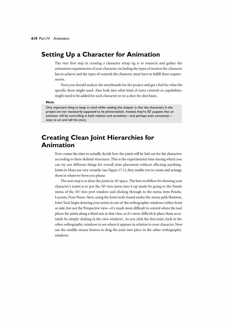
Figures 17.4 and 17.5 show the final laid-out skeletal structure of both characters in
the Parking Spot project.
613Chapter 17 Rigging Characters for Animation
Figure 17.4 The laid-out skeletal structure for Spot.
8/7/2019 Riggin 4 Character Anmtn
http://slidepdf.com/reader/full/riggin-4-character-anmtn 6/88
Figure 17.5 The laid-out skeletal structure for The Jerk.
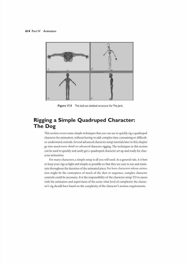
Rigging a Simple Quadruped Character:The Dog
This section covers some simple techniques that you can use to quickly rig a quadruped
character for animation, without having to add complex time-consuming or difficult-
to-understand controls. Several advanced character setup tutorials later in this chapter
go into much more detail on advanced character rigging. The techniques in this section
can be used to quickly and easily get a quadruped character set up and ready for char-
acter animation.
For many characters, a simple setup is all you will need. As a general rule, it is best
to keep your rigs as light and simple as possible so that they are easy to use and main-
tain throughout the duration of the animated piece.For hero characters whose anima-
tion might be the centerpiece of much of the shot or sequence, complex character
controls could be necessary. It is the responsibility of the character setup TD to assess
with the animators and supervisors of the scene what level of complexity the charac-
ter’s rig should have based on the complexity of the character’s motion requirements.
614 Part IV Animation
8/7/2019 Riggin 4 Character Anmtn
http://slidepdf.com/reader/full/riggin-4-character-anmtn 7/88
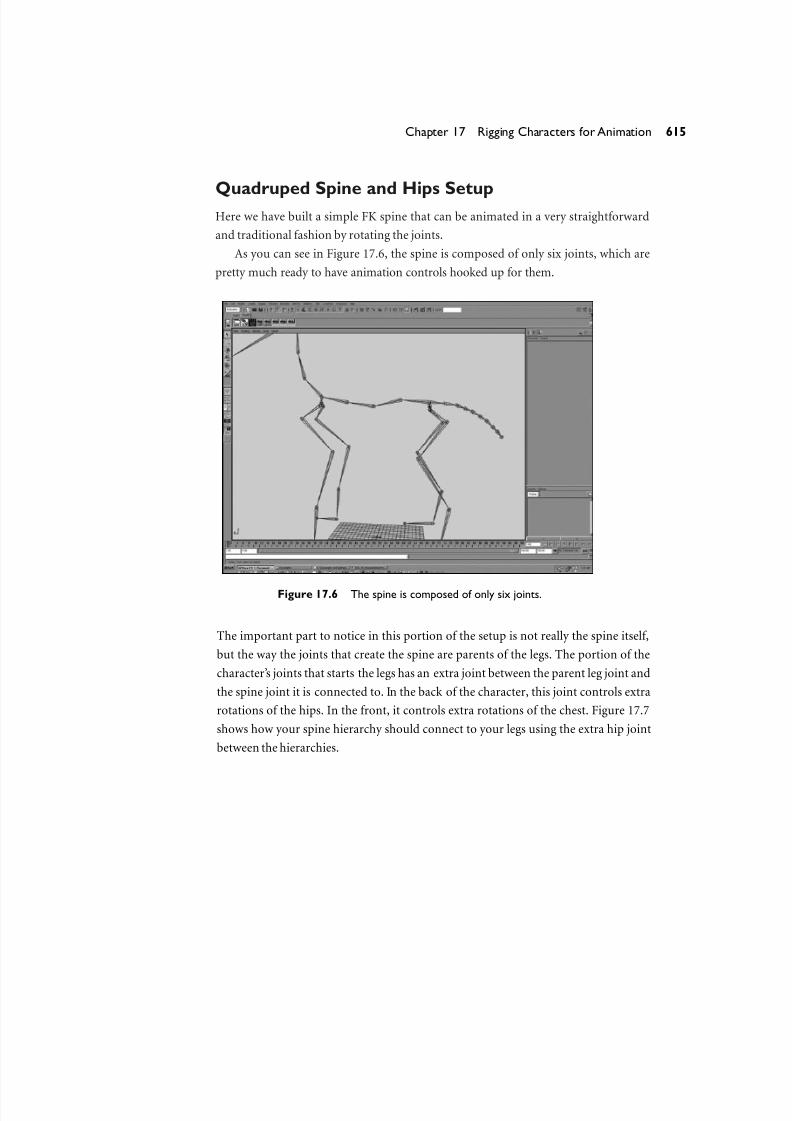
Quadruped Spine and Hips SetupHere we have built a simple FK spine that can be animated in a very straightforward
and traditional fashion by rotating the joints.
As you can see in Figure 17.6, the spine is composed of only six joints, which are
pretty much ready to have animation controls hooked up for them.
615Chapter 17 Rigging Characters for Animation
Figure 17.6 The spine is composed of only six joints.
The important part to notice in this portion of the setup is not really the spine itself,
but the way the joints that create the spine are parents of the legs. The portion of the
character’s joints that starts the legs has an extra joint between the parent leg joint and
the spine joint it is connected to. In the back of the character, this joint controls extra
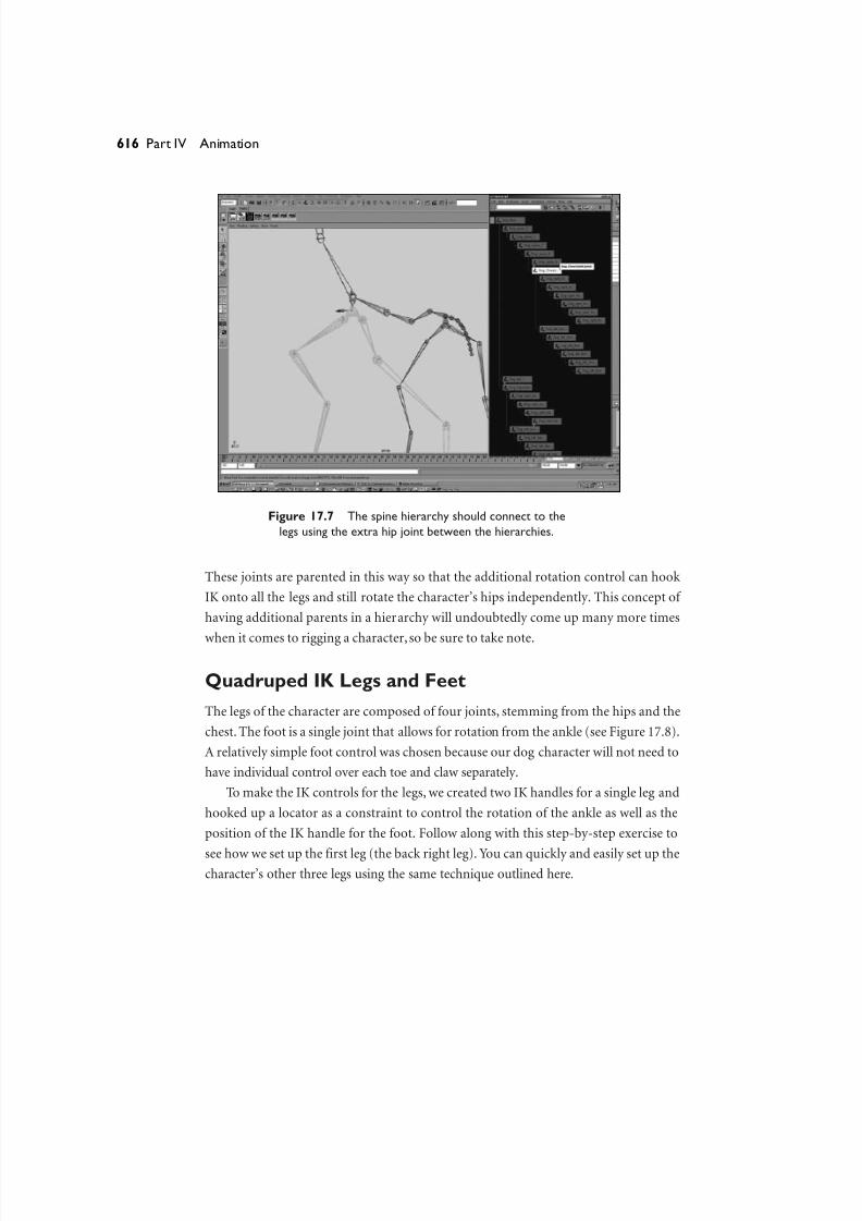
rotations of the hips. In the front, it controls extra rotations of the chest. Figure 17.7
shows how your spine hierarchy should connect to your legs using the extra hip joint
between the hierarchies.
8/7/2019 Riggin 4 Character Anmtn
http://slidepdf.com/reader/full/riggin-4-character-anmtn 8/88
Figure 17.7 The spine hierarchy should connect to the
legs using the extra hip joint between the hierarchies.
These joints are parented in this way so that the additional rotation control can hook
IK onto all the legs and still rotate the character’s hips independently. This concept of
having additional parents in a hierarchy will undoubtedly come up many more times
when it comes to rigging a character, so be sure to take note.
Quadruped IK Legs and Feet
The legs of the character are composed of four joints, stemming from the hips and the
chest. The foot is a single joint that allows for rotation from the ankle (see Figure 17.8).
A relatively simple foot control was chosen because our dog character will not need to
have individual control over each toe and claw separately.
To make the IK controls for the legs, we created two IK handles for a single leg and
hooked up a locator as a constraint to control the rotation of the ankle as well as the
position of the IK handle for the foot. Follow along with this step-by-step exercise to
see how we set up the first leg (the back right leg). You can quickly and easily set up thecharacter’s other three legs using the same technique outlined here.
616 Part IV Animation

8/7/2019 Riggin 4 Character Anmtn
http://slidepdf.com/reader/full/riggin-4-character-anmtn 9/88
Figure 17.8 The legs of the character are composed of four joints,
while the foot is a single joint that allows for rotation from the ankle.
Exercise 17.1 Creating Spot’s Hind Right Leg
Begin by creating an IK handle between two joints.
1. Open the file Dog_SkeletalHierarchy.mb from the CD that accompanies this book.
Use the IK Handle tool to create an IK handle from the Dog_right_backLeg_1 joint to
the Dog_right_backLeg_3 joint. Name the new IK handle thighIkHandle, and freeze
its transforms by choosing the menu command Modify, Freeze Transformations
while it is selected.
2. Create another IK handle from the Dog_right_backLeg_3 joint to the
Dog_right_backLegAnkle joint. Name this IK handle legIkHandle.
3. Create a locator by choosing the menu command Create, Locator. Point-snap it to
the legIKHandle by selecting the Move tool, pressing the v key, and, while holding
down the middle mouse button, dragging the locator to legIKHandle. Rename it
footIkControl.4. Create a null transform by clicking Ctrl+g with nothing selected. Next, point-snap
the null to the legIkHandle using the v key, as before.
617Chapter 17 Rigging Characters for Animation

8/7/2019 Riggin 4 Character Anmtn
http://slidepdf.com/reader/full/riggin-4-character-anmtn 10/88
Now you will give this null transform the same orientation and transform axis asthe Dog_right_backLegAnkle joint.
5. Select the null transform first, and then add to the selection
Dog_right_backLegAnkle by holding the Shift key and clicking it (it needs to be
last in the selection). Hit the p key to perform the parent operation. Next, perform
the menu command Modify, Freeze Transformations. This zeroes out the trans-
forms of the null and puts them into the space of the ankle joint (see Figure 17.9).
618 Part IV Animation
Figure 17.9 Clicking Modify, Freeze Transformations zeroes out the
transforms of the null and puts them into the space of the ankle joint.
6. Now unparent this null joint back to the world level by selecting it and clicking
the menu command Edit, Unparent.
7. Select and parent the footIkControl locator to the null transform node. Freeze the
footIkControl node’s transformations. It now has the same orientation as the
ankle joint.
8. Next, select footIkControl and use the Shift key to add legIkHandle to the end of
the selection list. Click Constrain, Point, select footIkControl and
Dog_right_backLegAnkle, in that order, and click Constrain, Orient.
You have just point-constrained the IK handle to this locator. You’ve also orient-constrained the foot so that rotating it rotates the foot and translating it moves
the IK for the leg.

8/7/2019 Riggin 4 Character Anmtn
http://slidepdf.com/reader/full/riggin-4-character-anmtn 11/88
You are just about finished with the setup for the leg. One last step is to add a polevector constraint.
9. Create a locator, and name it leg_poleVector. Now move it behind the back of the
character’s leg, on the side opposite the side of the leg that bends inward.
10. Next, select the leg_poleVector locator and legIkHandle, in that order, and click
Constrain, Pole Vector.
11. Now just group the leg_poleVector locator all by itself (to add an additional trans-
form above), and then point-constrain the group node to the Dog_HipsJoint
node. Select this new group along with the remaining IK handles in the
Hypergraph, as well as the null transform that is a parent of your foot control;
group them together using Ctrl+g. Name the new group IkLegControls (see
Figure 17.10).
619Chapter 17 Rigging Characters for Animation
Figure 17.10 The new group, IkLegControls.
12. Repeat the previous steps for each of the other legs. This step-by-step process
should go quite quickly when you get the hang of it.
13. When you are finished with all four legs, add prefix hierarchy names for each leg
by selecting each node together for a single leg, clicking Modify, Prefix Hierarchy
Names, and adding the prefix for that particular leg (for example, frontRightLeg_and backRightLeg_).

8/7/2019 Riggin 4 Character Anmtn
http://slidepdf.com/reader/full/riggin-4-character-anmtn 12/88
14. Next, select all four of your legs’ IkLegControls groups, group them together usingCtrl+g, and rename that group Leg_Controls.
15. Finally, group together the Leg_Controls and Dog_Root joint under a new group,
and call it DogMainTransform (see Figure 17.11).
620 Part IV Animation
Figure 17.11 The finished legs set up for the dog.
The finished file with all the legs rigged is named Dog_LegsSetup_Finished.mb on
the CD.
IK Spline Tail and Ears Setup
The technique used for the IK spline tail and ears setup is a very common combination
of IK splines, with some added FK-style control. The technique you will use in the next
exercise is basically to create a spline IK for the entire hierarchy of joints and then draw
a low-res joint hierarchy right on top of where the IK spline curve was created (usual-
ly two to three joints is enough). Next,you’ll simply smooth-bind the low-res joints to
the IK spline curve. This is a nice way to get some FK feeling control and still have the
ability to translate the joints for IK spline-style results.
8/7/2019 Riggin 4 Character Anmtn
http://slidepdf.com/reader/full/riggin-4-character-anmtn 13/88
Exercise 17.2 Character Setup for Spot’s Tail and EarsThis exercise again is performed only on the tail. The exact same technique should then
be used on the ears as well.
1. Start with the completed file from the last exercise, Dog_LegsSetup_Finished.mb,
which you can find on the accompanying CD.
2. Go to the IK Spline tool by clicking the menu item Skeleton, IK Spline Handle
Tool, Options Box. Hit the Reset Tool button at the bottom, and then be sure to
uncheck the Auto Simplify Curve and Auto Parent Curve options.
3. Draw an IK Spline curve from the root of the hierarchy, all the way to the last joint
in the hierarchy. In this case, it is a nine-joint tail; you create the spline handle
starting from the Dog_tail_1 joint and ending at the Dog_tail_9 joint.
4. Next, using the Joint tool and holding down the c key to enter Curve Snap mode,
draw a low-res four-joint hierarchy directly on top of the spline curve that was just
autocreated by the IK spline tool.
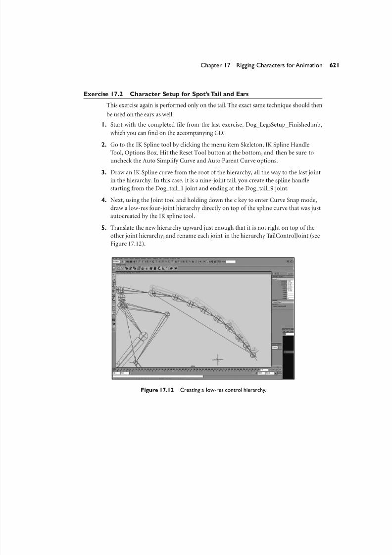
5. Translate the new hierarchy upward just enough that it is not right on top of the
other joint hierarchy, and rename each joint in the hierarchy TailControlJoint (see
Figure 17.12).
621Chapter 17 Rigging Characters for Animation
Figure 17.12 Creating a low-res control hierarchy.
8/7/2019 Riggin 4 Character Anmtn
http://slidepdf.com/reader/full/riggin-4-character-anmtn 14/88
6. Next, select the highest parent of the TailControlJoint hierarchy and Shift+selectthe NURBS curve that was created automatically by the IK spline tool. You might
have to use the Hypergraph to select this curve because the joints are in the way.
7. With the current selection, click Skin, Bind Skin, Smooth Bind using the default
options.
8. Select the root of the new low-res control hierarchy and parent it to the node that
you want to rotate the real tail hierarchy that has the IK spline solver attached to it.
In this case, I parented the new TailControlJoint hierarchy to the Dog_HipsJoint
node so that when you rotate the hips, the tail wags along with them.
9. Perform these steps for both the ears. The steps are exactly the same.
10. When you are finished, group any ungrouped spline IK handles as well as spline
IK curves under a new group node. Then put this group node somewhere in the
character’s hierarchy that will not have animation applied to it. In this case, I
added a new group node to DogMainTransform and called it Dog_character. This
group parents anything related to the character that should not be animated as a
child of it.
11. Be sure to lock the translates, rotates, and scales of the Dog_character group node.
Parent all the leftover IK controls and NURBS curves under the Dog_character
group node.
You can find the completed setup in the file Dog_TailAndEarSetup_Finished.mb
on the accompanying CD.
Low-Res Stand-In Geometry
As the following exercise shows, creating stand-in geometry is a very simple process.
This geometry is simply a low-resolution version of the actual character geometry,
which is then cut up into a separate piece per joint using a combination of the Cut Poly
Faces tool and the Poly Separate command. The cut polygon pieces are then simply
made a child of the joint that they correspond to. Now, the low-res geometry moves
with the joint hierarchy but is not bound or deforming, so it is extremely fast and
interactive for the animator to use.
622 Part IV Animation
8/7/2019 Riggin 4 Character Anmtn
http://slidepdf.com/reader/full/riggin-4-character-anmtn 15/88

8/7/2019 Riggin 4 Character Anmtn
http://slidepdf.com/reader/full/riggin-4-character-anmtn 16/88
Figure 17.14 Select the low-res polygon character, and activate the Cut Poly Faces tool.
4. Now, with the options from the previous figure, drag your mouse across the geom-
etry and watch as the Cut Faces tool creates a straight line across your geometry.
This is where the polygons will be cut when you release the tool. Cut the polygons.
Experiment with where you are cutting the geometry and how well it lines up with
the location of the joint.
5. Next, after you have cut the polygon, perform the menu commands Edit Polygons,
Separate and then Edit, Delete by Type, History.
6. Cut the geometry into a separate piece for each joint, trying not to cut across otherparts of the geometry that shouldn’t be split yet. Then, each time you cut, separate
the polygons and delete the history. Eventually, you will be finished cutting up the
entire geometry.
7. Next, one by one, select each polygon piece that you cut, and Shift+select the closest
joint that you cut that piece for. Hit the p key on your keyboard to parent the
geometry to the joint. Do this for each separate piece that you cut for the character.
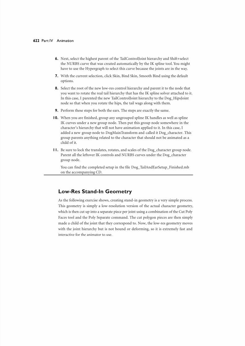
You can find the finished file with the low-resolution stand-in character properly
cut and parented in the file Dog_LowResStandIn_Finished.mb on the accompany-
ing CD.
624 Part IV Animation

8/7/2019 Riggin 4 Character Anmtn
http://slidepdf.com/reader/full/riggin-4-character-anmtn 17/88
Hooking Up Control Boxes to Your Character RigControl boxes are the visual handles that the character animator uses to animate the
character. The control boxes are an extra layer of setup hooked up to your skeleton’s
joints, IK, and hierarchical controls to give the animator a simple and intuitive way to
see and select all the controls for your character that are meant to be animated. All the
translation and rotation of your character should happen on character control boxes,
not on random locators or selection handles that are difficult to see or select.
Control boxes can be made of NURBS curves or of polygon objects that have been
disconnected from a shader. NURBS curves are the most common choice because you
can isolate them for selection while animating using the NURBS Curve option in the
Object Mode Pick Mask menu. You can also quickly view them on or off with the Show
NURBS Curve option of the Show menu of your current 3D view port window
(or from the HotBox).
Open the file CharacterControlBox.mb on the accompanying CD to see exactly
what a control box is.As you can see, it is just a NURBS curve that has been shaped so
that it creates a cubelike box shape—hence the name control box (see Figure 17.15).
Control boxes can, of course, be any shape and size (because they are just NURBS
curves), and the CVs of the curve itself can always be hand-tweaked to produce the
correct shape.
625Chapter 17 Rigging Characters for Animation
Figure 17.15 A control box.

8/7/2019 Riggin 4 Character Anmtn
http://slidepdf.com/reader/full/riggin-4-character-anmtn 18/88
You can hook up a control box to a rigged character in several ways. Basically, the maingoal is to in some way connect the transformation controls of the control box into the
transformation controls of the character rig. You can achieve this through expressions,
complex node networks, or just simple constraints or parenting relationships.
The most common and straightforward methods for hooking up control boxes to
your character are the following:
● Transform (object) parenting —Simply parent your control as a child of your
control box. This works easily and efficiently for things such as IK handles and
constrained locators, as well as groups that are meant to control translation or
rotation.
● Shape parenting —You do this by parenting the NURBS curves’ shape nodes
(not the transform, but the shape, which you have to load into the Hypergraph
and graph input and output connections to see and select). Making the NURBS
curve shape a child of the actual transform that you are trying to hook up the
control box for enables you to use the curve as a selection handle for the actual
joint or hierarchical animation control.
You can do this by first point-snapping the NURBS curve to the joint that you
want to hook it onto. Next,parent the NURBS curve transform to the joint and
click Modify, Freeze Transformations on the NURBS curve. Select the NURBS
curve shape. (Make sure the node says Shape at the end, in Hypergraph,Graph,
Input and Output Connections. Also be sure you have the shape selected, not
the transform.) Then Shift+select to add to the current selection the joint (or
any other transform node) that you want to hook up the NURBS curve as a se-
lection handle for. Then perform this MEL command:
parent –r –shape;
This parents the NURBS curve shape node under the transform for the joint.
Now you should be able to select the curve in the view port window, but in ac-
tuality you are selecting the transform of the object that you just parented the
NURBS curve shape onto.
● Grouped control boxes with constraints—Create a group node that has the
same orientation and translation space as the joint or node that you are hook-ing up the control box. Then make this node the parent of your control box.
You then freeze transforms on the control box and point-constrain it to the
626 Part IV Animation

8/7/2019 Riggin 4 Character Anmtn
http://slidepdf.com/reader/full/riggin-4-character-anmtn 19/88
joint that you are hooking up to. Orient-constrain the joint to the control boxso that it controls the rotations.
You can create a group node that has the same orientation and translation space
as the joint or node that you are hooking up the control box to in two different
ways. First, you can create a null transform by selecting nothing and then hit-
ting Ctrl+g. Next, you can give the null the same transform pivots as the joint or
node you are trying to hook up to.You do that in two ways:
● Point-,orient-, and scale-constrain the null transform node to the joint.
Then immediately delete the constraint nodes to give the null transform
node the same transform space as the joint.
●
Point-snap the null transform node directly on top of the joint. Then tem-porarily parent the null to the joint, freeze transforms on the null, and un-
parent it back into its original hierarchy to give the null transform node the
same transform space as the joint.
● Grouped control boxes with direct connections—Create a null group node,
and point- and orient-constrain it to the parent node of the actual joint or
transform that you are trying to hook the control box onto. Next, create a group
node that has the same orientation and translation space as the joint or node
that you are hooking the control box up to; make this node the parent of your
control box.Parent your control box group node under the constrained null.
Then freeze transforms on the control box and open the Connection Editor.
Load the NURBS curve’s rotates on the left side and the joint’s rotates on the
right, and directly connect them to one another so that the control box is dri-
ving the rotations of the joint. Even though they are directly connected, they
will always move together properly because the parents are linked with con-
straints and the nodes are both in the same transform space.
Connecting your control boxes is really a crucial element of rigging your character be-
cause it is one of the last steps before your character is ready for animation testing. treat
the process of hooking them up to your character accordingly. One thing to remember,
though, is that it really doesn’t matter how you get your control boxes hooked up to
control your character, as long they work correctly and move the correct nodes around.
Sometimes on simple characters you can get away with purely parenting techniques or
direct connections alone (which is perfectly acceptable). Another good idea when it
627Chapter 17 Rigging Characters for Animation

8/7/2019 Riggin 4 Character Anmtn
http://slidepdf.com/reader/full/riggin-4-character-anmtn 20/88
comes to hooking up your control boxes is to keep the translates and rotates of the con-trol boxes transforms capable of going back to zero as the default attribute state.
Therefore, if you need to move, scale, or position your control box, simply enter
Component mode and shape it using the control vertices. This also usually means
freezing the transforms before actually going through the process of connecting the
box to control a joint or other transform node.
Also remember that control boxes are simply used to select animation controls for
your character and to move the character around. The goal of these controls is that
they be immediately accessible and selectable from any view. Sometimes it is difficult,
but do whatever you can to make the controls easy to see and select from most angles.
This includes making controls somewhat uneven in shape or asymmetrical, as well as
color-coding so that if one is right on top of the other, it is still quite intuitive to differ-
entiate between the two control boxes.
Here are a few easy ways to color-code your control boxes in Maya:
● By clicking Display, Wireframe Color with the object selected, you can easily
change the color of just about any object without modifying attributes that
other parts of Maya directly use to change the color of the node as well (such
as the Layer Editor).
● Open the Attribute Editor of the node and expand the Object Display frame
layout.Then expand the Display Overrides subsection of the Object Display lay-
out. Next, turn on the check box that reads Enable Overrides.Now the lower
section that reads Color becomes enabled, and you can drag the slider andchoose any color that you want.
● Simply make a layer and assign your objects to that layer. Then just change the
layer color. This is the least preferred method because you really don’t want to
have to make a layer for every single object whose wireframe color you want to
change.
Note
Changing the wireframe display color affects only the OpenGL display of the node, not any
look or color attributes of the shader or the software-rendered elements. However, it affects
the “hardware”-rendered wireframe color.
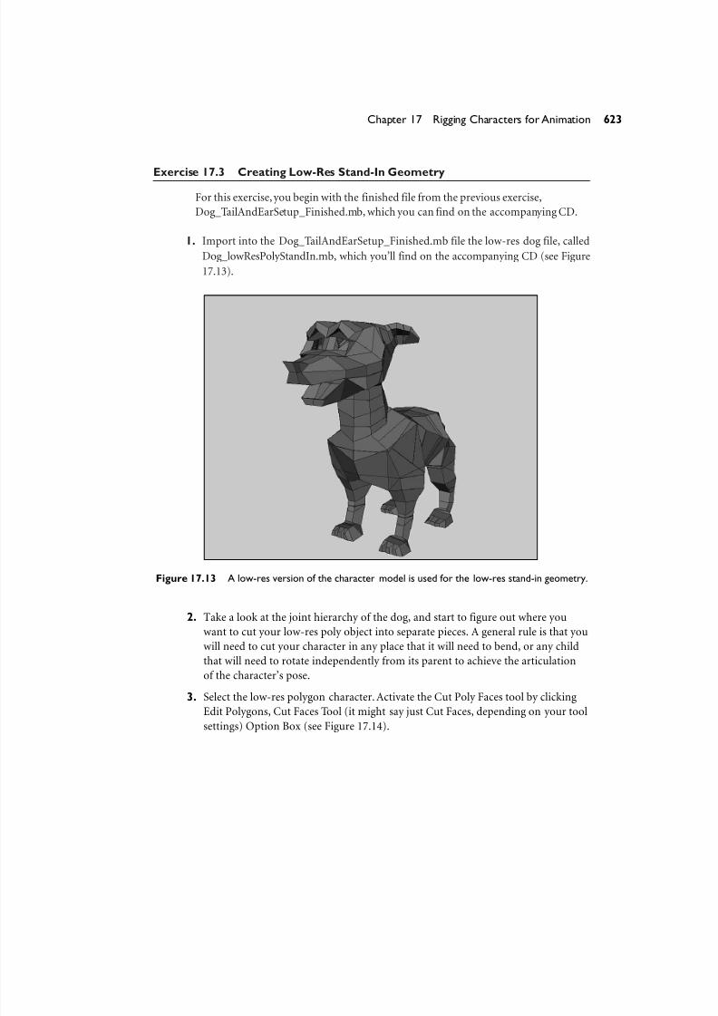
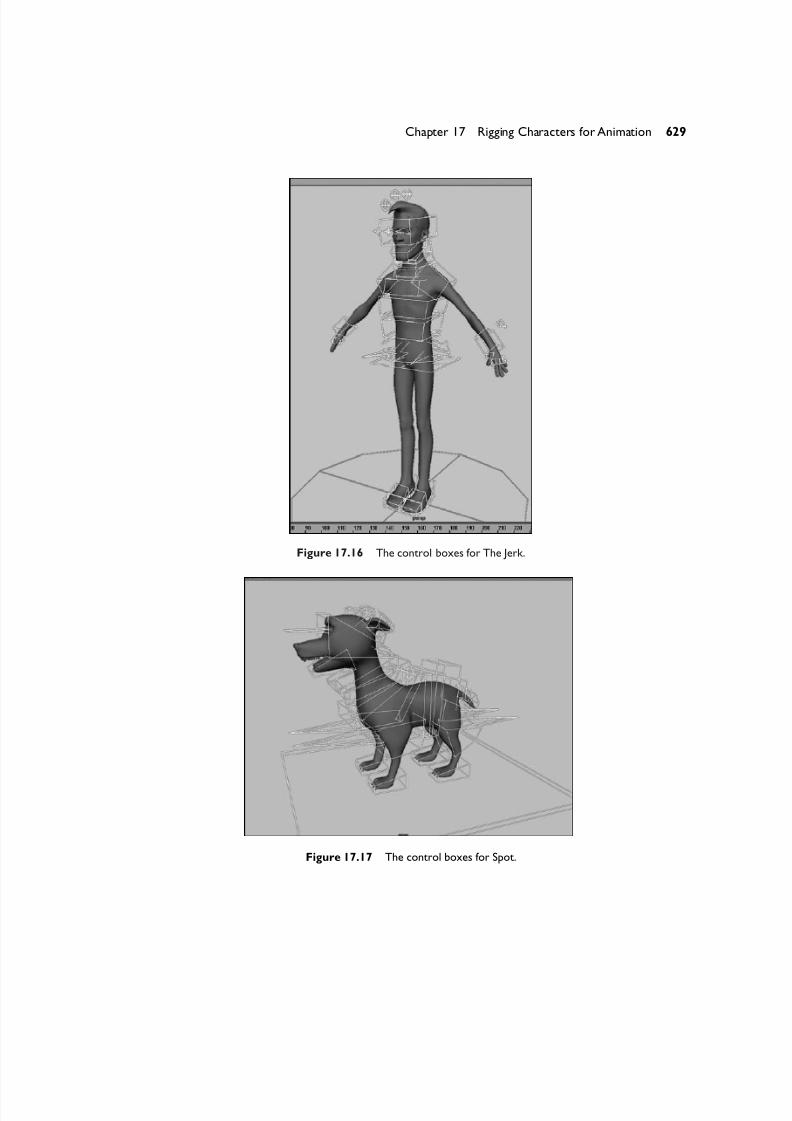
Figures 17.16 and 17.17 show the control boxes for The Jerk and Spot models,
respectively.
628 Part IV Animation
8/7/2019 Riggin 4 Character Anmtn
http://slidepdf.com/reader/full/riggin-4-character-anmtn 21/88
Figure 17.16 The control boxes for The Jerk.
629Chapter 17 Rigging Characters for Animation
Figure 17.17 The control boxes for Spot.

8/7/2019 Riggin 4 Character Anmtn
http://slidepdf.com/reader/full/riggin-4-character-anmtn 22/88
Creating Advanced Bipedal CharacterControlsThis section covers several more advanced approaches, some that lend themselves very
nicely to the stretching characters into any pose needed by the animators. We know
that our human character will need to stand on two feet, sit down and drive a car, get
sprayed by a fire hydrant, get knocked down, and interact with several objects and
props in his environment. The fact that the character might need to be animated with
a touch of cartooned style, per his character design, is also a consideration for the
design of the controls. A special type of rig involving a stretchy spline IK setup that
reacts with the intuitive controls of an FK hierarchy will be used for the back (spine) of
The Jerk. It will give him the ability to stretch his back evenly, similar to the real stretch-ing ability of a spine. It will also allow normal, traditional FK-style rotations of the con-
trols for certain poses that should not be controlled by an IK rotational element. The
ability to stretch more than would be anatomically correct will exist, and it will be the
animator’s job to decide how much the back will stretch, bend, and so on.
The legs of the character will be rigged using IK because The Jerk will need to stick
mostly to the ground for walking. The arms will also be rigged using IK, but a simple
IK parenting technique will be used to allow for FK-style rotation of the shoulders, as
well as IK-style translation placement for The Jerk’s clavicle and hand. This will give the
character animator full control to pose the characters. Both the arms and the legs of
The Jerk will have automatic stretching built into their IK rigs as well. This adds another
level of control for the animators, especially when sticking the feet or hands onto
objects, because the legs and arms will actually stretch to any length to meet the place-
ment of the hands or feet.
The Advanced Biped Spine
Let’s start the first advanced character setup exercise with creating what I have coined
“the Divine Spine.” There has been much talk about spine controls over the years, and
several techniques in Maya lend themselves to achieving promising results, but these
techniques are missing key elements from other styles of rigging that many animators
and riggers prefer. Thus arises the basic dilemma of character rigging: How do you
really manipulate the transformation space to achieve the ultimate combination of
motion capabilities, while still successfully maintaining straightforward ease of use and
production-level stability?
630 Part IV Animation

8/7/2019 Riggin 4 Character Anmtn
http://slidepdf.com/reader/full/riggin-4-character-anmtn 23/88
This advanced spine setup solves many, if not all, of the problems that certain pre-existing techniques for spine setups contain. It also combines the best of both FK con-
trols and IK controls, which enabling the animator to operate in both FK and IK
seamlessly at the same time while animating the character. No uncomfortable or unin-
tuitive switching on and off of weighted attributes is required. I designed the Divine
Spine setup with these requirements:
1. Be able to move the hips of the character without changing the location or mov-
ing the shoulders, and be able to move the shoulders without changing the posi-
tion of the hips.
2. Still be able to grab a control and rotate it in any direction. It should intuitively
rotate the character’s back hierarchically as if it were a simple FK joint hierarchy.
3. Be able to grab the same character control and translate it, and intuitively trans-late the character’s spine like a spline IK setup.
4. Be able to compress and stretch uniformly between vertebrae when the controls
are animated.
5. Be controlled by a minimal number of control joints, yet still allow for a large
number of actual spine joints.
6. Be stable, predictable, and production-worthy. It should not use some forced
mathematical function to compute secondary motion that will make the anima-
tor “fight” with the motion.
This spine setup is a versatile approach and can be used effectively to rig extremely
realistic spine controls as well as cartooney ones.
Without further ado, let’s begin.
Exercise 17.4 The Divine Spine Setup
1. First, create your joint hierarchy and orient the joints. I usually use a total of 12 to 18
joints for the base hierarchy of the spinal column, but you can use more or less, de-
pending on your character’s requirements. For this setup to work properly, you must
be sure of the following things:
● Scale Compensate is turned on in the Joint tool options before you draw your
joints.
● All your joints have been properly oriented before proceeding, with the Scale
option checked on in the Orient Joint options window before you perform the
Orient Joint operation (see Figure 17.18).
631Chapter 17 Rigging Characters for Animation
8/7/2019 Riggin 4 Character Anmtn
http://slidepdf.com/reader/full/riggin-4-character-anmtn 24/88
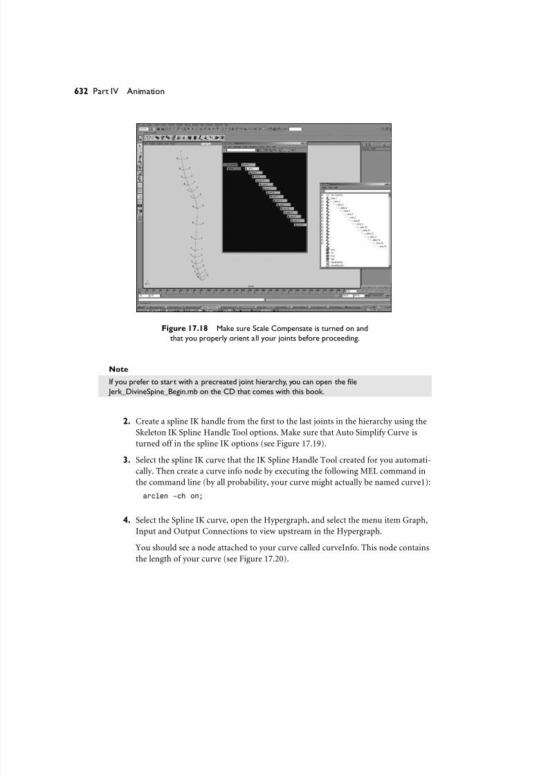
Figure 17.18 Make sure Scale Compensate is turned on and
that you properly orient all your joints before proceeding.
Note
If you prefer to start with a precreated joint hierarchy, you can open the file
Jerk_DivineSpine_Begin.mb on the CD that comes with this book.
2. Create a spline IK handle from the first to the last joints in the hierarchy using the
Skeleton IK Spline Handle Tool options. Make sure that Auto Simplify Curve is
turned off in the spline IK options (see Figure 17.19).
3. Select the spline IK curve that the IK Spline Handle Tool created for you automati-
cally. Then create a curve info node by executing the following MEL command in
the command line (by all probability, your curve might actually be named curve1):
arclen –ch on;
4. Select the Spline IK curve, open the Hypergraph, and select the menu item Graph,
Input and Output Connections to view upstream in the Hypergraph.
You should see a node attached to your curve called curveInfo. This node contains
the length of your curve (see Figure 17.20).
632 Part IV Animation

8/7/2019 Riggin 4 Character Anmtn
http://slidepdf.com/reader/full/riggin-4-character-anmtn 25/88
Figure 17.19 Make sure that Auto Simplify Curve is turned off in the spline IK options.
633Chapter 17 Rigging Characters for Animation
Figure 17.20 The curveInfo node contains the length of your curve.
8/7/2019 Riggin 4 Character Anmtn
http://slidepdf.com/reader/full/riggin-4-character-anmtn 26/88
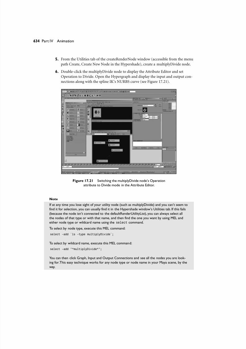
5. From the Utilities tab of the createRenderNode window (accessible from the menupath Create, Create New Node in the Hypershade), create a multiplyDivide node.
6. Double-click the multiplyDivide node to display the Attribute Editor and set
Operation to Divide. Open the Hypergraph and display the input and output con-
nections along with the spline IK’s NURBS curve (see Figure 17.21).
634 Part IV Animation
Figure 17.21 Switching the multiplyDivide node’s Operation
attribute to Divide mode in the Attribute Editor.
Note
If at any time you lose sight of your utility node (such as multiplyDivide) and you can’t seem to
find it for selection, you can usually find it in the Hypershade window’s Utilities tab. If this fails
(because the node isn’t connected to the defaultRenderUtilityList), you can always select all
the nodes of that type or with that name, and then find the one you want by using MEL and
either node type or wildcard name using the select command.
To select by node type, execute this MEL command:
select –add `ls –type multiplyDivide`;
To select by wildcard name, execute this MEL command:select –add “*multiplyDivide*”;
You can then click Graph, Input and Output Connections and see all the nodes you are look-
ing for.This easy technique works for any node type or node name in your Maya scene, by the
way.
8/7/2019 Riggin 4 Character Anmtn
http://slidepdf.com/reader/full/riggin-4-character-anmtn 27/88
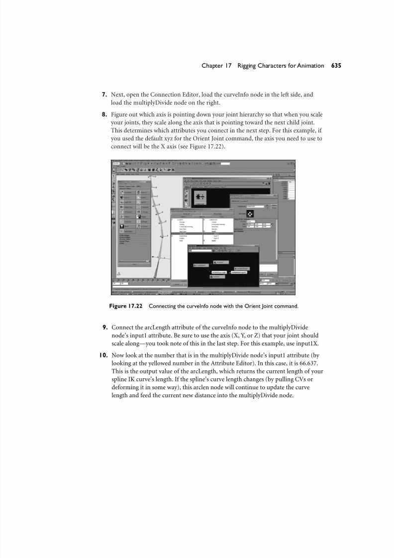
7. Next, open the Connection Editor, load the curveInfo node in the left side, andload the multiplyDivide node on the right.
8. Figure out which axis is pointing down your joint hierarchy so that when you scale
your joints, they scale along the axis that is pointing toward the next child joint.
This determines which attributes you connect in the next step. For this example, if
you used the default xyz for the Orient Joint command, the axis you need to use to
connect will be the X axis (see Figure 17.22).
635Chapter 17 Rigging Characters for Animation
Figure 17.22 Connecting the curveInfo node with the Orient Joint command.
9. Connect the arcLength attribute of the curveInfo node to the multiplyDivide
node’s input1 attribute. Be sure to use the axis (X, Y, or Z) that your joint should
scale along—you took note of this in the last step. For this example, use input1X.
10. Now look at the number that is in the multiplyDivide node’s input1 attribute (by
looking at the yellowed number in the Attribute Editor). In this case, it is 66.637.
This is the output value of the arcLength, which returns the current length of your
spline IK curve’s length. If the spline’s curve length changes (by pulling CVs or
deforming it in some way), this arclen node will continue to update the curve
length and feed the current new distance into the multiplyDivide node.
8/7/2019 Riggin 4 Character Anmtn
http://slidepdf.com/reader/full/riggin-4-character-anmtn 28/88
Now you want to create a normalized ratio that represents the amount that thecurve length is scaling (if a CV of the curve gets moved) to drive the scale attribute
of each joint in the hierarchy. This is easily achieved by dividing the current dis-
tance (the yellow one) by the initial distance before the deforming took place. So,
as common sense would dictate, the output at the default state always equals a
scale of 1. The curve has not yet been deformed, so the current distance just hap-
pens to also be exactly what you need for the initial distance.
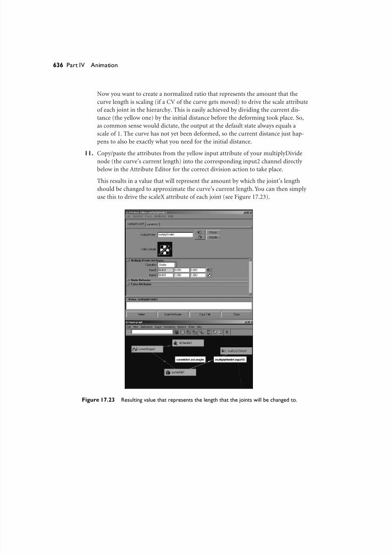
11. Copy/paste the attributes from the yellow input attribute of your multiplyDivide
node (the curve’s current length) into the corresponding input2 channel directly
below in the Attribute Editor for the correct division action to take place.
This results in a value that will represent the amount by which the joint’s length
should be changed to approximate the curve’s current length. You can then simply
use this to drive the scaleX attribute of each joint (see Figure 17.23).
636 Part IV Animation
Figure 17.23 Resulting value that represents the length that the joints will be changed to.
8/7/2019 Riggin 4 Character Anmtn
http://slidepdf.com/reader/full/riggin-4-character-anmtn 29/88
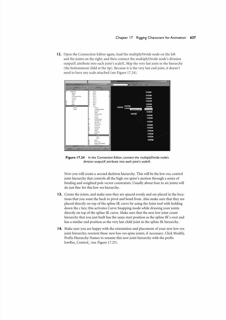
12. Open the Connection Editor again, load the multiplyDivide node on the leftand the joints on the right, and then connect the multiplyDivide node’s division
outputX attribute into each joint’s scaleX. Skip the very last joint in the hierarchy
(the bottommost child at the tip). Because it is the very last end joint, it doesn’t
need to have any scale attached (see Figure 17.24).
637Chapter 17 Rigging Characters for Animation
Figure 17.24 In the Connection Editor, connect the multiplyDivide node’s
division outputX attribute into each joint’s scaleX.
Now you will create a second skeleton hierarchy. This will be the low-res, control
joint hierarchy that controls all the high-res spine’s motion through a series of
binding and weighted pole vector constraints. Usually about four to six joints will
do just fine for this low-res hierarchy.
13. Create the joints, and make sure they are spaced evenly and are placed in the loca-
tions that you want the back to pivot and bend from. Also make sure that they are
placed directly on top of the spline IK curve by using the Joint tool with holding
down the c key; this activates Curve Snapping mode while drawing your joints
directly on top of the spline IK curve. Make sure that the new low joint count
hierarchy that you just built has the same start position as the spline IK’s root and
has a similar end position as the very last child joint in the spline IK hierarchy.
14. Make sure you are happy with the orientation and placement of your new low-res
joint hierarchy; reorient these new low-res spine joints, if necessary. Click Modify,
Prefix Hierarchy Names to rename this new joint hierarchy with the prefix
lowRes_Control_ (see Figure 17.25).

8/7/2019 Riggin 4 Character Anmtn
http://slidepdf.com/reader/full/riggin-4-character-anmtn 30/88
Figure 17.25 Rename the low-res joint hierarchy.
15. Now select the spline curve and Shift+select the lowRes joint hierarchy’s root.
Smooth-bind the curve to the lowRes joint hierarchy.
16. Test how the low-res joint hierarchy bends your spline IK setup so far. If you are
unhappy with the arc or curve of the bend, hit Undo (the z key) a few times until
you are back to the point where you can start rebuilding your low-res joint hierar-chy. Do this test a few times until you get the right placement and number of
joints for your low-res joint hierarchy (see Figure 17.26).
17. Next, even out the weighting of your smooth bound curve by distributing the
curve’s CV weights more evenly across the joints. Do this by selecting the CVs of
the curve and using the Smooth Skins tab under General Editors, Component
Editor. Modify the weights by changing some of the values at 1 to .5, or .75,
depending on how close they are to the neighboring joint (see Figure 17.27).
638 Part IV Animation

8/7/2019 Riggin 4 Character Anmtn
http://slidepdf.com/reader/full/riggin-4-character-anmtn 31/88
Figure 17.26 Testing the low-res joint hierarchy on the spline IK setup.
639Chapter 17 Rigging Characters for Animation
Figure 17.27 Using the Component Editor to modify the weights.

8/7/2019 Riggin 4 Character Anmtn
http://slidepdf.com/reader/full/riggin-4-character-anmtn 32/88
Now the problem you have is that the spline IK hierarchy bends and compressesreally nicely, but it doesn’t twist (due to the nature of the spline IK solver’s pole
vector ). Although the spline IK solver has a rotation plane implemented and is
controllable by using the twist attribute, you don’t want to use this attribute to
drive the twisting of the spine—it will violate the intuitive control that an anima-
tor expects to have when he rotates one of the single joint controls of the low-res
skeleton. At this point you really need a rotate plane at every single joint, which
has a weighted average to control the twisting of the spine based on the twisting of
the low-res control joints. Unfortunately, the spline IK allows only a single rotate
plane that is distributed evenly over the entire hierarchy.
So, in the following steps you will create yet one more hierarchy of joints. This
time it will be an exact duplicate of the spline IK hierarchy—but without the spline
IK and with a weighted pole vector–constrained ikRPsolver IK handle at every sin-gle joint.
18. Select the root joint of the original spine’s spline IK joint hierarchy and duplicate
it using the default duplicate options. Delete the unused effector node in the new
duplicated hierarchy, which got duplicated from the other spline hierarchy. (Make
sure you delete only the effectors of the duplicated hierarchy, not the effector that
the IK spline solver is connected to.)
19. Click Modify, Prefix Hierarchy Names to rename this duplicated hierarchy to have
a new prefix of Ik_Bind_Spine_. This is the spine that the character mesh eventu-
ally will be bound onto (see Figure 17.28).
640 Part IV Animation
Figure 17.28 This is the spine that the character mesh eventually will be bound onto.

8/7/2019 Riggin 4 Character Anmtn
http://slidepdf.com/reader/full/riggin-4-character-anmtn 33/88
Note
This situation will result in the creation of three hierarchies in the end. One of them (the oneyou just duplicated) will have the character’s skin bound to it and will be partially controlled by
the original stretchy spine splineIk hierarchy.These two hierarchies will need to stay unpar-
ented from any group that will transform with the character because these two hierarchies will
be entirely controlled by the lowRes spine that is currently smooth-skinned to the spine’s
spline curve. If you transform the bound IK spline hierarchy as well as the low-res control
spine, you get double transforms. I discuss this later, but hopefully this helps enlighten things a
little bit more for now.
20. Translate this duplicated Ik_Bind_Spine_ hierarchy’s root node away from the
spline IK hierarchy so that this whole situation isn’t completely confusing when
you try to select and rig up your joints in the 3D view window.
You now want to create rotate plane IK handles at each joint of the newIk_Bind_Spine_ hierarchy by starting with the root and then making an IK handle
that is a single joint long using the IK Handle tool.
21. Select the first joint and then the very next joint in the hierarchy going up the
spine. Then start the next IK handle’s base at the end location of the previous IK
handle that was just created; continue this process until the end of the spine hier-
archy is reached (see Figure 17.29). This procedure should exactly result in the
same number of IK handles as there are joints in your hierarchy, minus one—the
only joint that does not have an IK handle stuck directly on top of it should be the
root (which will later be point-constrained).
641Chapter 17 Rigging Characters for Animation
Figure 17.29 Creating rotate plane IK handles at each joint of the new Ik_Bind_Spine_ hierarchy.

8/7/2019 Riggin 4 Character Anmtn
http://slidepdf.com/reader/full/riggin-4-character-anmtn 34/88
Now you will perform a few steps to perfectly line up the rpIk spine with thespline IK spine.
22. First, point-constrain each one of the rpIk handles to the corresponding joint that
is part of the spline IK hierarchy. Then point-constrain the root of the
Ik_Bind_Spine_ rpIk hierarchy directly to the root of the spline IK hierarchy (see
Figures 17.30 and 17.31).
642 Part IV Animation
Figure 17.30 This image shows half of the IK handles as they arebeing point-constrained to the corresponding splineIk spine joints.
23. Next, connect the scale attributes from each original joint in the spline IK hierar-
chy to the scale attributes of the corresponding duplicate joint in the
Ik_Bind_Spine_ rpIk joint hierarchy.
Because these two hierarchies are right on top of each other in the 3D view, the
easiest way to select them is by looking at the two hierarchies side by side in the
Hypergraph’s Graph, Scene Graph mode. Then hit the Toggle Free Form Layout
button and move the hierarchies side by side. By doing this, you can see exactly
which nodes you need to connect to each other because each node in the hierar-
chy is right next to the corresponding one. Because the hierarchies are exactly thesame, you simply need to open the Connection Editor, select a single spine joint
first, and load it into the left side. Select the corresponding duplicate
Ik_Bind_Spine_ joint second, and load it into the right side. Then quickly connect
the scale attribute of the spine to the scale attribute of the corresponding
IK_Bind_Spine.

8/7/2019 Riggin 4 Character Anmtn
http://slidepdf.com/reader/full/riggin-4-character-anmtn 35/88
Figure 17.31 This image shows all of the IK handles after they have been point-constrained
to the corresponding splineIk spine joints.The root of the Ik_Bind_Spine_ has been
point-constrained to the root of the splineIk’s spine joint root.
24. Next, group all the rpIk handles under one node by selecting them all and hitting
Ctrl+g (see Figure 17.32).
643Chapter 17 Rigging Characters for Animation
Figure 17.32 Group all the rpIk handles under one node.

8/7/2019 Riggin 4 Character Anmtn
http://slidepdf.com/reader/full/riggin-4-character-anmtn 36/88
You should now have three joint hierarchies that, for the most part, all movetogether and are controlled by the low-res control hierarchy. They have the capa-
bility of stretching and compressing, as well as rotating using an FK approach and
translating using an IK approach. The only part missing is the FK capability to
actually twist the low-res joint hierarchy and have the joints in the high-res joint
hierarchy get the separate portions driven by the twist.
To achieve the desired twisting capability, you will create locators to serve as
weighed poleVector constraints for each rotate plane IK handle in the rpIk
Ik_Bind_Spine_ hierarchy.
25. Before beginning, hide the lowRes control hierarchy temporarily so that it doesn’t
confuse things in the 3D view. Do this by selecting the root of the lowRes hierar-
chy and hitting Ctrl+h.
26. Start by creating a single locator, and name it poleVector1. Next, activate the
Move tool, and with the middle mouse button on your mouse, and the v key on
your keyboard depressed, drag your mouse to snap the locator directly on top of
the root joint of the high-res hierarchies. When the locator is directly on top of the
root joint, translate it along the Z-axis direction that moves it backward so that it
is directly behind the character’s back. Be sure that it is moving only on a single
axis and that you are moving it behind the character.
27. Next, hit Ctrl+d to duplicate the locator and snap this new duplicated locator to
the next joint, which should also have an IK handle right on top of it. Perform the
exact same step, moving the locator backward about the same distance on the
same axis as the first locator that you just moved behind the character. Repeat this
step for each joint in the hierarchy except for the very last one.
28. When you are finished duplicating, snapping, and moving all the locators behind
the character, check that you have the correct number of locators. You should have
a single locator for each rpIk handle, and each locator should be located directly
behind each one of the character’s spine joints, with a single IK handle for each
joint except the root. Your locators should be situated something like the ones
shown in Figure 17.33.
29. Next, unhide the low-res control joints by setting the root node’s visibility
attribute to on. Parent each one of the poleVector# locators to the nearest low-res
control joint (see Figure 17.34).
644 Part IV Animation

8/7/2019 Riggin 4 Character Anmtn
http://slidepdf.com/reader/full/riggin-4-character-anmtn 37/88
8/7/2019 Riggin 4 Character Anmtn
http://slidepdf.com/reader/full/riggin-4-character-anmtn 38/88
30. Now pole vector–constrain each rpIk handle so that it is constrained to all of thelocators. Do this by first selecting all the locators that you have situated and par-
ented behind your character’s back; then add to the last selection the rpik handle
and perform the command Constrain, Pole Vector.
This creates a single weighted pole vector constraint with weight attributes for
each locator, which constrains the IK handle onto all the locators situated behind
your character.
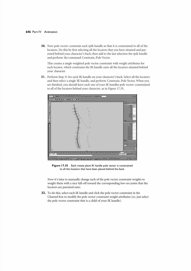
31. Perform Step 31 for each IK handle on your character’s back: Select all the locators
and then select a single IK handle, and perform Constrain, Pole Vector. When you
are finished, you should have each one of your IK handles pole vector–constrained
to all of the locators behind your character, as in Figure 17.35.
646 Part IV Animation
Figure 17.35 Each rotate plane IK handle pole vector is constrained
to all the locators that have been placed behind the back.
Now it’s time to manually change each of the pole vector constraint weights to
weight them with a nice fall-off toward the corresponding low-res joints that the
locators are parented onto.
32. To do this, select each IK handle and click the pole vector constraint in the
Channel box to modify the pole vector constraint weight attributes (or, just select
the pole vector constraint that is a child of your IK handle).
8/7/2019 Riggin 4 Character Anmtn
http://slidepdf.com/reader/full/riggin-4-character-anmtn 39/88
Now look at the weight values that show up in the Channel box. Each weight rep-resents how much the current IK handle’s twisting is controlled by each locator
that it is constrained to (the locators are children of the low-res back).
33. Set each weight value to a number that will distribute the rotation of the pole vec-
tor to be controlled evenly by two to four of the locators.
Rotating a low-res joint causes the pole vector constraint locator that is a child to
orbit around the pivot of the low-res joint you are rotating. This, in turn, causes
any of the IK handles that are constrained to the locator to twist or rotate along
the IK handle’s rotate plane. The idea is to determine which low-res joint’s rota-
tions you want to have affect the twisting of the high-res joints.
Determining which joints should receive weighting is quite simple: If the joint is at
the top of the hierarchy, weight it toward the locators that are children of the toplow-res joint. The best part about all this is that the poleVector constraint has
weights, so it can have weights that are falling off from one locator to the next,
across multiple joints. If one of your rpIk handles is in between the top low-res
joint and one of the middle low-res joints, give it weights that are averaged
between locators that are children of these two hierarchies. For example, if you are
distributing the weights across four locators, choose weights that are falling off
from low values to higher values, such as .1, .35, .75, and 1; the rest of the weights
should be set to 0. The only rule for which constraint weights you should give
higher weights to is this: Set the weights of the pole vector constraints so that
when you twist the low-res hierarchy, the high-res joints rotate with an appealing
and desirable fall-off between them.
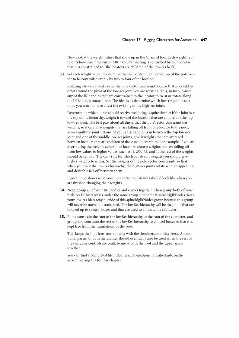
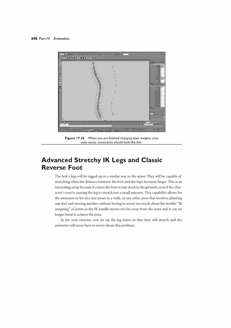
Figure 17.36 shows what your pole vector constraints should look like when youare finished changing their weights.
34. Next, group all of your IK handles and curves together. Then group both of your
high-res IK hierarchies under the same group and name it spineRigIkNodes. Keep
your low-res hierarchy outside of this spineRigIkNodes group because this group
will never be moved or translated. The lowRes hierarchy will be the joints that are
hooked up to control boxes and that are used to animate the character.
35. Point-constrain the root of the lowRes hierarchy to the root of the character, and
group and constrain the rest of the lowRes hierarchy to control boxes so that it is
kept free from the translations of the root.
This keeps the hips free from moving with the shoulders, and vice versa. An addi-
tional parent of both hierarchies should eventually also be used when the rest of
the character controls are built, to move both the root and the upper spine
together.
You can find a completed file, titled Jerk_DivineSpine_Finished.mb, on the
accompanying CD for this chapter.
647Chapter 17 Rigging Characters for Animation
8/7/2019 Riggin 4 Character Anmtn
http://slidepdf.com/reader/full/riggin-4-character-anmtn 40/88
Figure 17.36 When you are finished changing their weights, your
pole vector constraints should look like this.
Advanced Stretchy IK Legs and ClassicReverse Foot
The Jerk’s legs will be rigged up in a similar way to the spine: They will be capable of
stretching when the distance between the foot and the hips becomes larger. This is an
interesting setup because it causes the foot to stay stuck to the ground, even if the char-
acter’s root is causing the leg to stretch just a small amount. This capability allows for
the animator to hit nice key poses in a walk, or any other pose that involves planting
one foot and moving another, without having to worry too much about the terrible “IK
snapping” of joints as the IK handle moves too far away from the joint and it can no
longer bend to achieve the pose.
In the next exercise, you set up the leg joints so that they will stretch and the
animator will never have to worry about this problem.
648 Part IV Animation
8/7/2019 Riggin 4 Character Anmtn
http://slidepdf.com/reader/full/riggin-4-character-anmtn 41/88
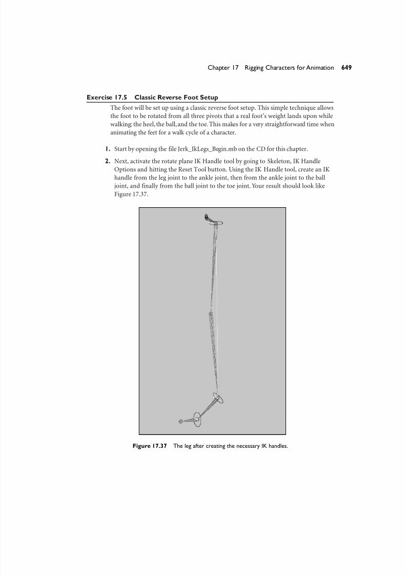
Exercise 17.5 Classic Reverse Foot SetupThe foot will be set up using a classic reverse foot setup. This simple technique allows
the foot to be rotated from all three pivots that a real foot’s weight lands upon while
walking: the heel, the ball,and the toe.This makes for a very straightforward time when
animating the feet for a walk cycle of a character.
1. Start by opening the file Jerk_IkLegs_Begin.mb on the CD for this chapter.
2. Next, activate the rotate plane IK Handle tool by going to Skeleton, IK Handle
Options and hitting the Reset Tool button. Using the IK Handle tool, create an IK
handle from the leg joint to the ankle joint, then from the ankle joint to the ball
joint, and finally from the ball joint to the toe joint. Your result should look like
Figure 17.37.
649Chapter 17 Rigging Characters for Animation
Figure 17.37 The leg after creating the necessary IK handles.
8/7/2019 Riggin 4 Character Anmtn
http://slidepdf.com/reader/full/riggin-4-character-anmtn 42/88
3. Next, rename all your IK handles to match the portions of the leg and foot thatthey correspond to—ankle_ikHandle, ball_ikHandle, and toe_ikHandle.
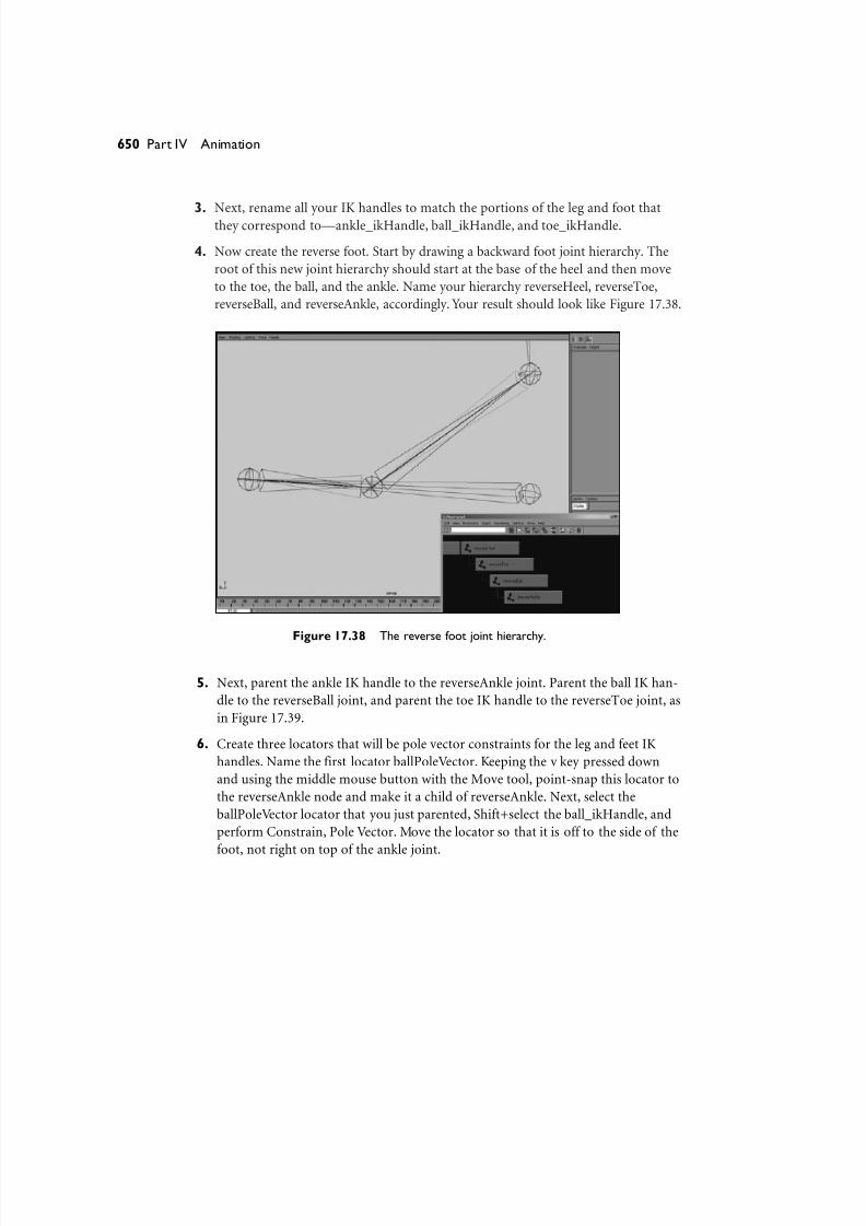
4. Now create the reverse foot. Start by drawing a backward foot joint hierarchy. The
root of this new joint hierarchy should start at the base of the heel and then move
to the toe, the ball, and the ankle. Name your hierarchy reverseHeel, reverseToe,
reverseBall, and reverseAnkle, accordingly. Your result should look like Figure 17.38.
650 Part IV Animation
Figure 17.38 The reverse foot joint hierarchy.
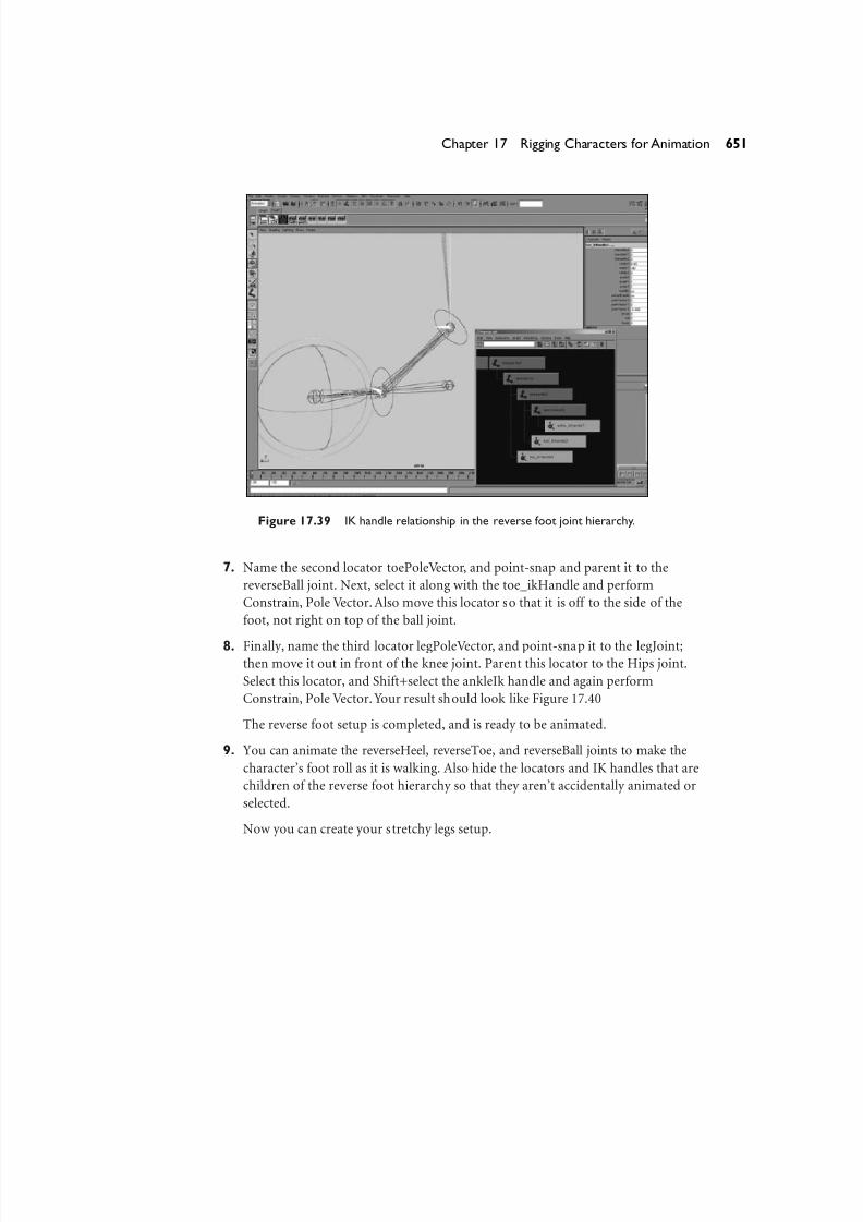
5. Next, parent the ankle IK handle to the reverseAnkle joint. Parent the ball IK han-
dle to the reverseBall joint, and parent the toe IK handle to the reverseToe joint, as
in Figure 17.39.
6. Create three locators that will be pole vector constraints for the leg and feet IK
handles. Name the first locator ballPoleVector. Keeping the v key pressed down
and using the middle mouse button with the Move tool, point-snap this locator to
the reverseAnkle node and make it a child of reverseAnkle. Next, select the
ballPoleVector locator that you just parented, Shift+select the ball_ikHandle, and
perform Constrain, Pole Vector. Move the locator so that it is off to the side of the
foot, not right on top of the ankle joint.
8/7/2019 Riggin 4 Character Anmtn
http://slidepdf.com/reader/full/riggin-4-character-anmtn 43/88
Figure 17.39 IK handle relationship in the reverse foot joint hierarchy.
7. Name the second locator toePoleVector, and point-snap and parent it to the
reverseBall joint. Next, select it along with the toe_ikHandle and perform
Constrain, Pole Vector. Also move this locator so that it is off to the side of the
foot, not right on top of the ball joint.
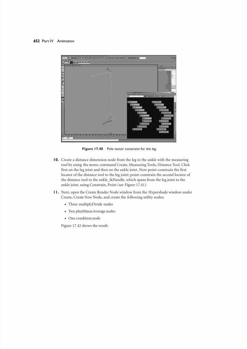
8. Finally, name the third locator legPoleVector, and point-snap it to the legJoint;then move it out in front of the knee joint. Parent this locator to the Hips joint.
Select this locator, and Shift+select the ankleIk handle and again perform
Constrain, Pole Vector. Your result should look like Figure 17.40
The reverse foot setup is completed, and is ready to be animated.
9. You can animate the reverseHeel, reverseToe, and reverseBall joints to make the
character’s foot roll as it is walking. Also hide the locators and IK handles that are
children of the reverse foot hierarchy so that they aren’t accidentally animated or
selected.
Now you can create your stretchy legs setup.
651Chapter 17 Rigging Characters for Animation
8/7/2019 Riggin 4 Character Anmtn
http://slidepdf.com/reader/full/riggin-4-character-anmtn 44/88
Figure 17.40 Pole vector constraint for the leg.
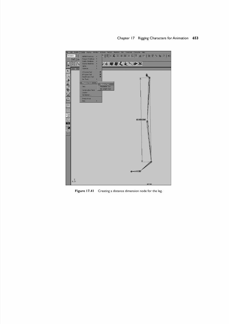
10. Create a distance dimension node from the leg to the ankle with the measuring
tool by using the menu command Create, Measuring Tools, Distance Tool. Click
first on the leg joint and then on the ankle joint. Now point-constrain the first
locator of the distance tool to the leg joint; point-constrain the second locator of
the distance tool to the ankle_ikHandle, which spans from the leg joint to the
ankle joint, using Constrain, Point (see Figure 17.41).
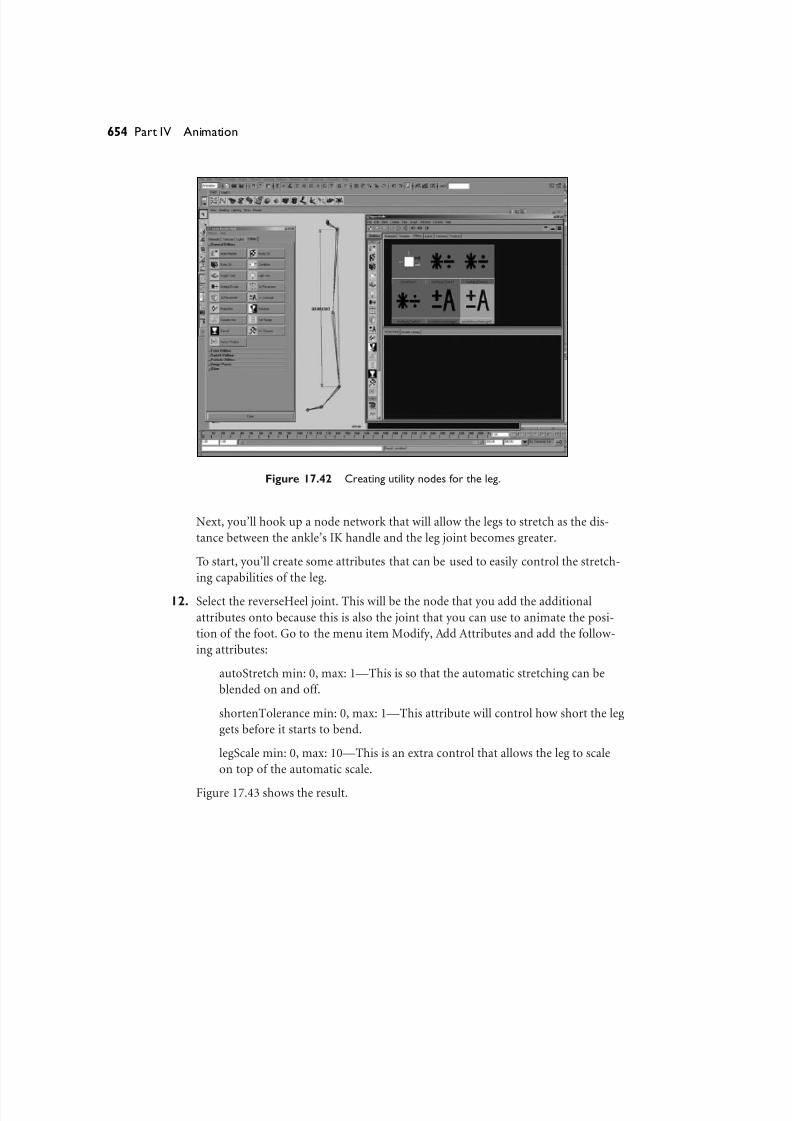
11. Next, open the Create Render Node window from the Hypershade window under
Create, Create New Node, and create the following utility nodes:
● Three multiplyDivide nodes
● Two plusMinusAverage nodes
● One condition node
Figure 17.42 shows the result.
652 Part IV Animation
8/7/2019 Riggin 4 Character Anmtn
http://slidepdf.com/reader/full/riggin-4-character-anmtn 45/88
Figure 17.41 Creating a distance dimension node for the leg.
653Chapter 17 Rigging Characters for Animation
8/7/2019 Riggin 4 Character Anmtn
http://slidepdf.com/reader/full/riggin-4-character-anmtn 46/88
Figure 17.42 Creating utility nodes for the leg.
Next, you’ll hook up a node network that will allow the legs to stretch as the dis-
tance between the ankle’s IK handle and the leg joint becomes greater.
To start, you’ll create some attributes that can be used to easily control the stretch-
ing capabilities of the leg.
12. Select the reverseHeel joint. This will be the node that you add the additional
attributes onto because this is also the joint that you can use to animate the posi-
tion of the foot. Go to the menu item Modify, Add Attributes and add the follow-
ing attributes:
autoStretch min: 0, max: 1—This is so that the automatic stretching can be
blended on and off.
shortenTolerance min: 0, max: 1—This attribute will control how short the leg
gets before it starts to bend.
legScale min: 0, max: 10—This is an extra control that allows the leg to scale
on top of the automatic scale.
Figure 17.43 shows the result.
654 Part IV Animation

8/7/2019 Riggin 4 Character Anmtn
http://slidepdf.com/reader/full/riggin-4-character-anmtn 47/88
Figure 17.43 The new leg attributes are ready to be connected.
Now you’ll connect all the nodes and attributes that you just created to get the
controllable automatic stretchy reaction that you want from the leg.
13. Connect the distanceDimensionShape.distance attribute to the
multiplyDivide1.input1Y attribute. Set the operation mode of multiplyDivide1
node to Divide. Next, copy and paste the number from input1Y (using Ctrl+c and
Ctrl+v) into the input2Y attribute of the multiplyDivide1 node.
14. Next, connect the multiplyDivide1 outputY to the plusMinusAverage1 input1D[0]
attribute. Make sure that the plusMinusAverage1 node’s operation is set to
Subtract. Also make sure that the multipyDivide1 node’s input2Z attribute is set
to 1. Then connect it to the plusMinusAverate input1D[1] attribute (to subtract 1
from the output).
15. Connect the plusMinusAverage1 node’s output1D to the multiplyDivide2 node’s
input2Y. Connect the reverseHeel’s autoStretch attribute into the input1Y attribute
of the multiplyDivide2 node.
16. Connect the multiplyDivide node’s outputY attribute to the plusMinusAverage
node’s input1D[0]. Then set the multiplyDivide2 node’s input2z attribute to 1 and
connect it to the input1D[1] attribute of the plusMinusAverage2 node.
655Chapter 17 Rigging Characters for Animation

8/7/2019 Riggin 4 Character Anmtn
http://slidepdf.com/reader/full/riggin-4-character-anmtn 48/88
17. Set the operation mode of the condition1 node to Less Than, and connect theplusMinusAverage2 node’s output1D attribute to the condition node’s
colorIfFalseG attribute. Then connect the plusMinusAverage2 node’s output1D
attribute to the condition node’s firstTerm attribute. Next, connect reverseHeel’s
shortenTolerance attribute to the condition node’s secondTerm attribute, and also
connect reverseHeel’s shortenTolerance attribute to the condition node’s
colorIfTrueG attribute.
18. Next, connect the condition1 node’s outColorG to the last multiplyDivide3 node’s
input1Y attribute. Connect reverseHeel’s attribute legScale to multiplyDivide3’s
input2Y attribute.
19. Finally, connect the outputY attribute of the multiplyDivide3 node into the scaleX
attributes of the leg and the knee joint nodes.
Your final node network should look similar to Figure 17.44.
656 Part IV Animation
Figure 17.44 The final node network for the stretchy leg.
You can now animate the reverse feet, and the leg will actually stretch to compensate
for the overextension of the foot. The attributes to control this reaction are right on
the reverseHeel, so you can keyframe this behavior on and off and scale the legs
on top of it. The completed scene file appears on the accompanying CD as
Jerk_IkLegs_Finished.mb.

8/7/2019 Riggin 4 Character Anmtn
http://slidepdf.com/reader/full/riggin-4-character-anmtn 49/88
Advanced IK Arms and Clavicular TriangleIn the next exercise, you will see how I chose to rig The Jerk’s shoulders and arms. The
technique used enables the arms to stretch and the shoulder to rotate as if it were an FK
arm. Separate controls exist for posing the arm using IK from the scapula, the clavicle,
and the shoulder, as well as the traditional IK handle at the wrist. Two locators both
have the wrist’s IK handle constrained to them, adding the capability to plant the char-
acter’s hand any place we choose. Two extra joints were inserted as children of the
shoulder and elbow but were not connected (not made parents) with the rest of the hi-
erarchy of the arm. These unparented children joints were used for better deformations
on the twisting of the shoulder and the wrist, to avoid the painful washboard effect.
Exercise 17.6 Advanced Stretchy IK Arms and the Clavicular Triangle
Begin by opening the file Jerk_ArmSetup_Begin.mb, which you’ll find on the accom-
panying CD. Take a look at how the arm joints are laid out to create the hierarchy.
Examine this file closely: It contains the joint placement for the entire skeletal hier-
archy that will create the final arm for The Jerk. The only thing missing is the controls,
which you will add to the rig now. You begin with the shoulder area of the character,
which I refer to as “the clavicular triangle.” Then you tackle the advanced stretchy IK
arm controls that will allow the character’s arms to stretch to any length. You’ll also
transition the hand to be stuck on any object and stay there while the rest of the body is
animated. So, let’s get started with the clavicular triangle.
1. Beginning with the file Jerk_ArmSetup_Begin.mb from the CD,create an IK handlefrom the clavicularTriangle joint node to the scapulaJoint node. Do this by clicking
Skeleton, IK Handle Tool Options; first hit the Reset Tool button and then select the
nodes in order from the 3D view port window. Rename the newly created IK handle
scapulaClavicle_IkControl.
2. Next, select the scapulaJoint and use the Ctrl+h key combination to temporarily
hide it so that you can select the correct node in the view port window. Now, using
the same settings in the IK Handle tool from above, create another IK handle from
the clavicleJoint node to the clavToShoulder joint node. Rename the newly created
IK handle clavicleStretch_IkHandle.
3. Next, use the Ctrl+Shift+h keyboard combination to unhide the last hidden node
(the scapulaJoint node). Then select the clavicleJoint node and use Ctrl+h to
temporarily hide it.
657Chapter 17 Rigging Characters for Animation

8/7/2019 Riggin 4 Character Anmtn
http://slidepdf.com/reader/full/riggin-4-character-anmtn 50/88
4. Using the same settings, create an IK handle from the scapulaJoint node to theshoulderJoint node. Rename this newly created IK handle
clavicleShoulder_IkControl.
5. Create one last IK handle from the shoulderJoint node all the way down to the
bottom of the arm to the wristJoint node. Rename the newly created IK handle
armWrist_IkControl. Now Ctrl+Shift+h to unhide the previously hidden
clavicleJoint.
6. Next, parent the clavicleShoulder_IkControl under the scapulaClavicle_IkControl
node. Then parent the clavicleStretch_IkHandle and the armWrist_IkControl
nodes to the clavicleShoulder_IkControl. Finally, parent the entire group of the
scapulaClavicle_IkControl node to the connectToSpine joint node. Your hierarchy
so far should look like Figure 17.45.
658 Part IV Animation
Figure 17.45 Hierarchy for the clavicle shoulder setup.
7. Now that you’ve parented all your IK appropriately, select all four IK handles and
perform the Modify, Freeze Transformations menu command. Next, with all the
IK still selected, highlight the poleVectorX, poleVectorY, and poleVectorZ
attributes in the Channel box and set them all to 0 (zero).
8/7/2019 Riggin 4 Character Anmtn
http://slidepdf.com/reader/full/riggin-4-character-anmtn 51/88
8. Next, click Create, Measure Tools, Distance Tool. While holding down the v key on your keyboard (Snap mode), snap a distance locator from the clavicleJoint
to the clavToShoulder joint. Rename each locator appropriately: clavicleJointPoint
and clavToShoulderPoint. Also rename the distanceDimension node that was
created to clavToShoulder_distanceDimension.
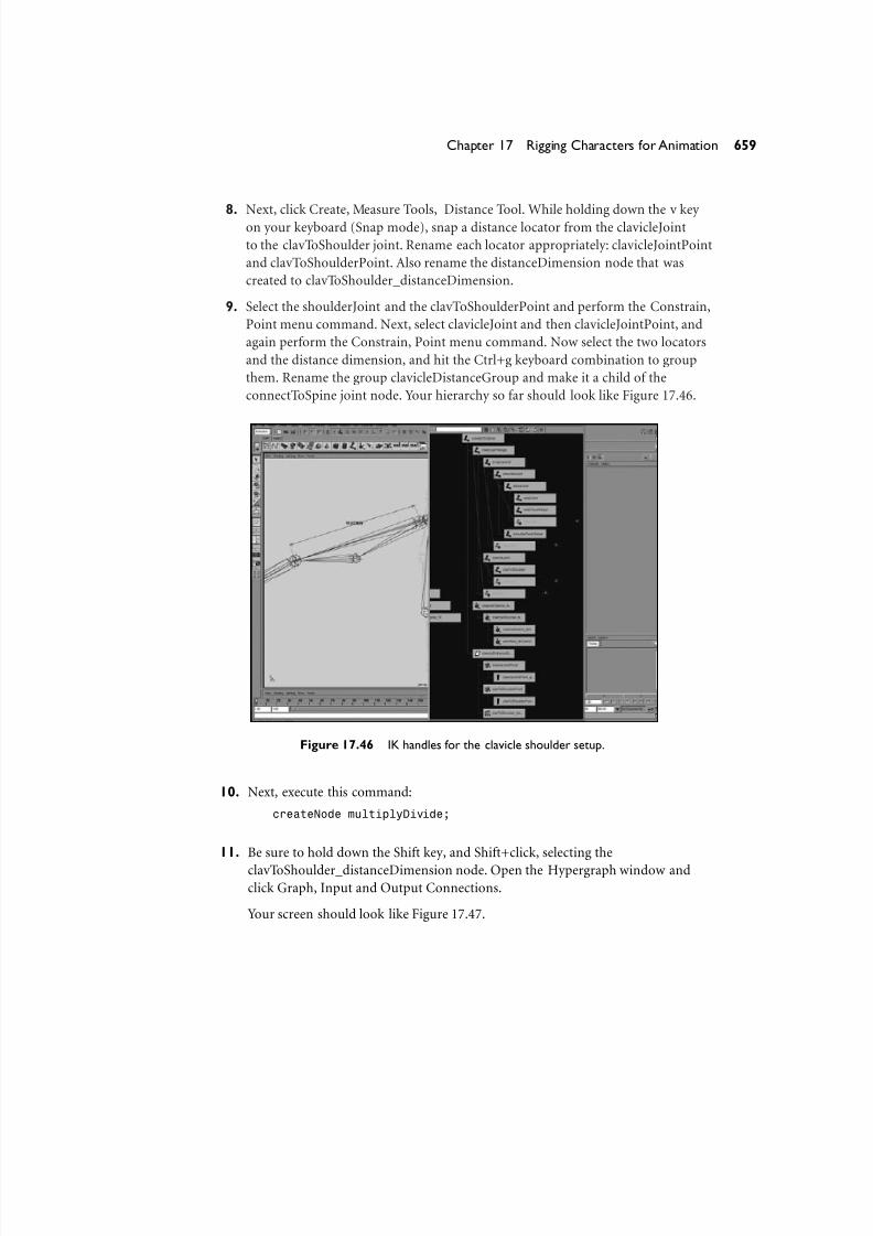
9. Select the shoulderJoint and the clavToShoulderPoint and perform the Constrain,
Point menu command. Next, select clavicleJoint and then clavicleJointPoint, and
again perform the Constrain, Point menu command. Now select the two locators
and the distance dimension, and hit the Ctrl+g keyboard combination to group
them. Rename the group clavicleDistanceGroup and make it a child of the
connectToSpine joint node. Your hierarchy so far should look like Figure 17.46.
659Chapter 17 Rigging Characters for Animation
Figure 17.46 IK handles for the clavicle shoulder setup.
10. Next, execute this command:
createNode multiplyDivide;
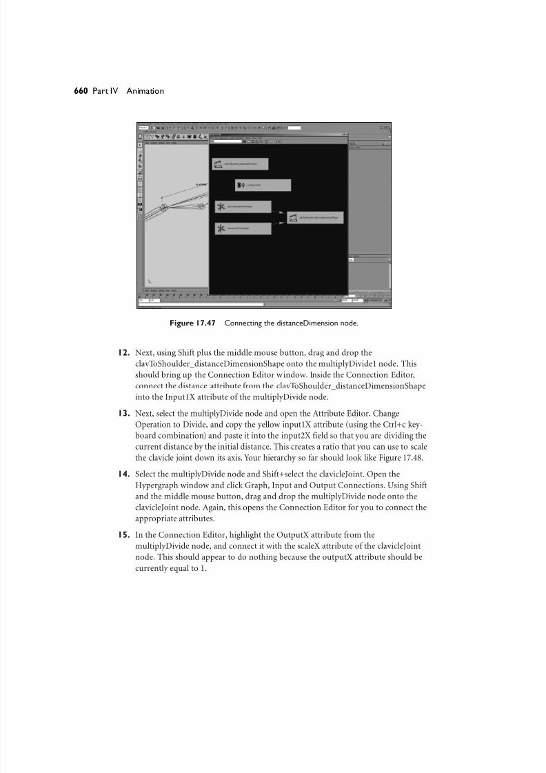
11. Be sure to hold down the Shift key, and Shift+click, selecting the
clavToShoulder_distanceDimension node. Open the Hypergraph window andclick Graph, Input and Output Connections.
Your screen should look like Figure 17.47.
8/7/2019 Riggin 4 Character Anmtn
http://slidepdf.com/reader/full/riggin-4-character-anmtn 52/88
Figure 17.47 Connecting the distanceDimension node.
12. Next, using Shift plus the middle mouse button, drag and drop the
clavToShoulder_distanceDimensionShape onto the multiplyDivide1 node. This
should bring up the Connection Editor window. Inside the Connection Editor,
connect the distance attribute from the clavToShoulder_distanceDimensionShape
into the Input1X attribute of the multiplyDivide node.
13. Next, select the multiplyDivide node and open the Attribute Editor. Change
Operation to Divide, and copy the yellow input1X attribute (using the Ctrl+c key-
board combination) and paste it into the input2X field so that you are dividing the
current distance by the initial distance. This creates a ratio that you can use to scale
the clavicle joint down its axis. Your hierarchy so far should look like Figure 17.48.
14. Select the multiplyDivide node and Shift+select the clavicleJoint. Open the
Hypergraph window and click Graph, Input and Output Connections. Using Shift
and the middle mouse button, drag and drop the multiplyDivide node onto the
clavicleJoint node. Again, this opens the Connection Editor for you to connect the
appropriate attributes.
15. In the Connection Editor, highlight the OutputX attribute from the
multiplyDivide node, and connect it with the scaleX attribute of the clavicleJoint
node. This should appear to do nothing because the outputX attribute should be
currently equal to 1.
660 Part IV Animation
8/7/2019 Riggin 4 Character Anmtn
http://slidepdf.com/reader/full/riggin-4-character-anmtn 53/88
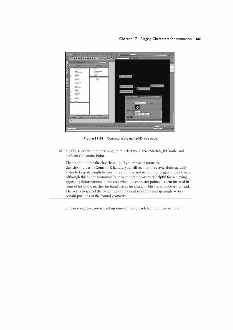
Figure 17.48 Connecting the multiplyDivide node.
16. Finally, select the shoulderJoint, Shift+select the clavicleStretch_IkHandle, and
perform Constrain, Point.
That is about it for the clavicle setup. If you move or rotate the
clavicleShoulder_IkControl IK handle, you will see that the clavicleJoint actually
scales to keep its length between the shoulder and its point of origin at the clavicle.Although this is not anatomically correct, it can prove very helpful for achieving
appealing deformations in this area when the character points his arm forward in
front of his body, reaches his hand across his chest, or lifts his arm above his head.
The key is to spread the weighting of this joint smoothly and sparingly across
certain portions of the frontal geometry.
In the next exercise, you will set up some of the controls for the entire arm itself.
661Chapter 17 Rigging Characters for Animation
8/7/2019 Riggin 4 Character Anmtn
http://slidepdf.com/reader/full/riggin-4-character-anmtn 54/88
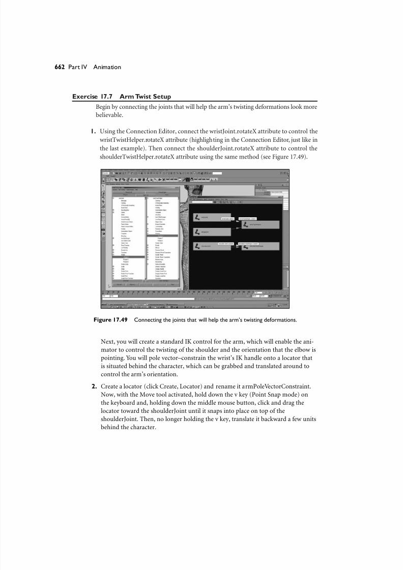
Exercise 17.7 Arm Twist SetupBegin by connecting the joints that will help the arm’s twisting deformations look more
believable.
1. Using the Connection Editor, connect the wristJoint.rotateX attribute to control the
wristTwistHelper.rotateX attribute (highlighting in the Connection Editor, just like in
the last example). Then connect the shoulderJoint.rotateX attribute to control the
shoulderTwistHelper.rotateX attribute using the same method (see Figure 17.49).
662 Part IV Animation
Figure 17.49 Connecting the joints that will help the arm’s twisting deformations.
Next, you will create a standard IK control for the arm, which will enable the ani-
mator to control the twisting of the shoulder and the orientation that the elbow is
pointing. You will pole vector–constrain the wrist’s IK handle onto a locator that
is situated behind the character, which can be grabbed and translated around to
control the arm’s orientation.
2. Create a locator (click Create, Locator) and rename it armPoleVectorConstraint.
Now, with the Move tool activated, hold down the v key (Point Snap mode) on
the keyboard and, holding down the middle mouse button, click and drag the
locator toward the shoulderJoint until it snaps into place on top of the
shoulderJoint. Then, no longer holding the v key, translate it backward a few units
behind the character.
8/7/2019 Riggin 4 Character Anmtn
http://slidepdf.com/reader/full/riggin-4-character-anmtn 55/88
3. Make the armPoleVectorConstraint locator a child of the connectToSpine node by selecting the armPoleVectorConstraint and then the connectToSpine; then hit the
p key on your keyboard.
4. Select the armPoleVectorConstraint locator and Shift-click the
armWrist_IkControl node to add it to the selection. Create a pole vector constraint
by using the menu command Constrain, Pole Vector.
5. Select the armPoleVectorConstraint locator and perform Modify, Freeze
Transformations to zero the locator’s transforms.
Next, you will create the extra controls that will allow the hand to be “planted” or
stuck on any object. For example, if the character needs to lean his hand against
the wall, grab onto a pole and swing around on it, or even just hold on to a steer-
ing wheel, this setup will easily allow for it.
The way you’ll accomplish this is very simple indeed. First, you’ll create two loca-
tors and parent them under the same group as the armWrist_IkControl. Then you
will create weighted point and orient constraints from these two locators onto the
armWrist_IkControl node. Finally, you will add an attribute that will control the
weight of the constraints that were added, to determine which locator the IK han-
dle gets constrained onto. Let’s get started.
6. First, create two locators. Rename one locator plantIkHand. Rename the other
locator freeIkHand.
7. With the Move tool activated, hold down the v key (Point Snap mode) on the key-
board and, holding down the middle mouse button, click and drag both locators
toward the wrist’s armWrist_IkControl in the 3D view port until they snap intoplace directly on top of the armWrist_IkControl.
8. Next, parent both the plantIkHand and freeIkHand locators under the same
parent as the armWrist_IkControl node (the scapulaClavicle_IkControl) by
selecting the two locators and Shift+selecting the scapulaClavicle_IkControl to
add it to the selection last; then hit the p key on your keyboard.
Next, you will create an empty “null” transform node that you’ll use to parent the
IK handle and both locators under so that they are in the same orientation and
position as the wristJoint node. You can then orient-constrain the wrist to the IK
handle without changing the current orientation of the wrist.
9. Create the null transform by first being sure that nothing is selected and then
hitting the Ctrl+g keyboard combination.
663Chapter 17 Rigging Characters for Animation
8/7/2019 Riggin 4 Character Anmtn
http://slidepdf.com/reader/full/riggin-4-character-anmtn 56/88
10. With the new null node created, point-snap it to the wristJoint node using theSnap mode of the Move tool by holding down the v key while clicking and drag-
ging with the middle mouse button held down. Zero the null node’s transforms by
selecting it and performing Modify, Freeze Transformations.
To put this null node into the same orientation as the wristJoint, you will point-
and orient-constrain it and immediately delete these constraints by executing a
single line of MEL code supplied in the next step.
11. A quick and easy way to do this is to execute the following MEL command in the
command line (first select the wristJoint node and Shift+select the null node to
add to the selection). Now execute the following bit of tricky code (which actually
creates constraints for you and then automatically deletes them immediately after-
ward so that they will line up your nodes but not keep them controlled via a con-
straint relationship—all at the same time):
delete 'orientConstraint'; delete 'pointConstraint';
12. Rename the null node to be called wristTransformCompensation. Parent it under
the same node as the armWrist_IkControl IK handle and plantIkHand and
freeIkHand locators by first selecting the wristTransformCompensation,
Shift+selecting the clavicleShoulder_IkControl node, and hitting the p key on the
keyboard.
The null transform is now in the same orientation space as the wristJoint, but it
will travel correctly under the clavicleShoulder_IkControl IK handle node. You will
now make this new wristTransformCompensation null node the parent of the
armWrist_IkControl IK handle and plantIkHand and freeIkHand locators.
13. Select all three of these nodes (armWrist_IkControl, plantIkHand, and
freeIkHand), and Shift+select the wristTransformCompensation null node to add
it to the selection last. Hit the p key to parent the IK and locators to this null node.
Note
If the wrist and elbow seem to pop into a different spot when you parent the
armWrist_IkControl IK handle, you can correct this. Simply select the armPoleVectorConstraint,
highlight all its translate channels in the Channel box, and then hit 0 and the Enter key.This
update problem occurs because of the nature of Maya’s lazy dependency graph evaluations.
664 Part IV Animation
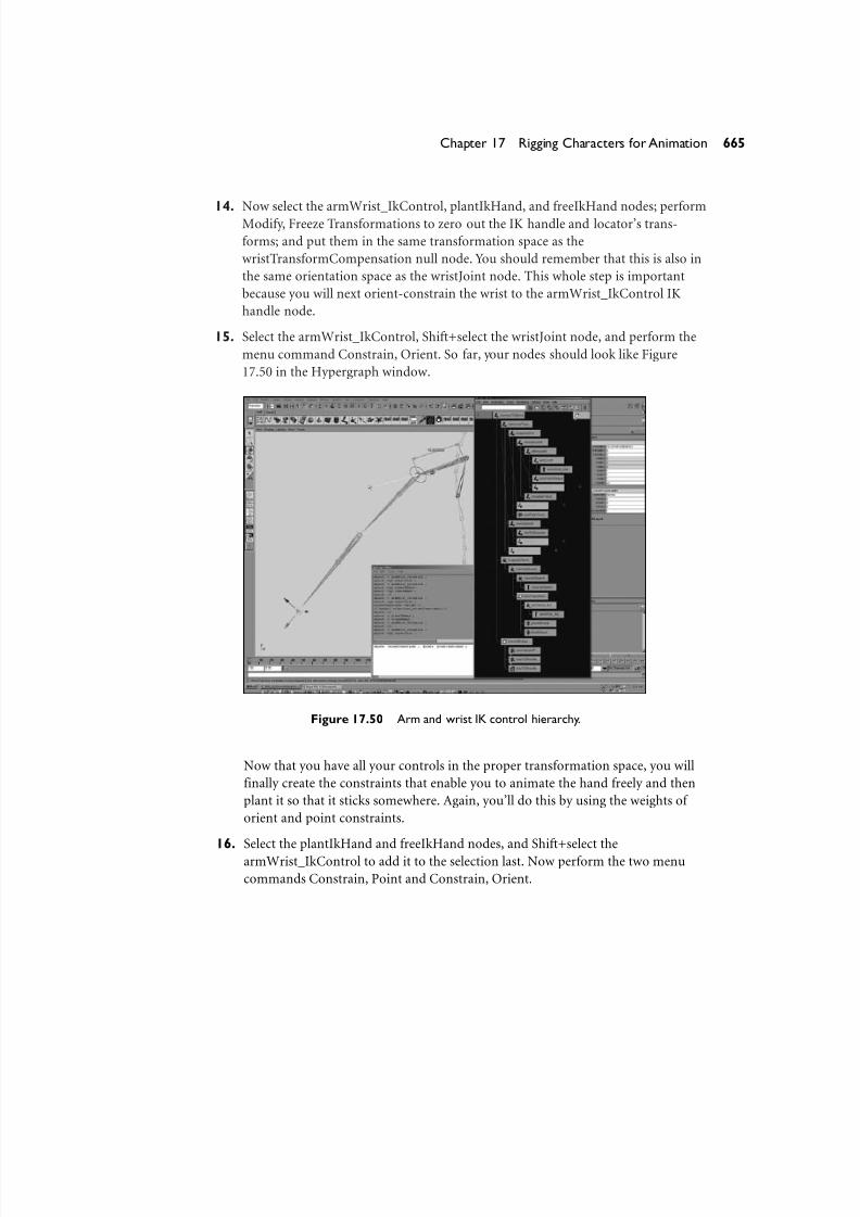
8/7/2019 Riggin 4 Character Anmtn
http://slidepdf.com/reader/full/riggin-4-character-anmtn 57/88
14. Now select the armWrist_IkControl, plantIkHand, and freeIkHand nodes; performModify, Freeze Transformations to zero out the IK handle and locator’s trans-
forms; and put them in the same transformation space as the
wristTransformCompensation null node. You should remember that this is also in
the same orientation space as the wristJoint node. This whole step is important
because you will next orient-constrain the wrist to the armWrist_IkControl IK
handle node.
15. Select the armWrist_IkControl, Shift+select the wristJoint node, and perform the
menu command Constrain, Orient. So far, your nodes should look like Figure
17.50 in the Hypergraph window.
665Chapter 17 Rigging Characters for Animation
Figure 17.50 Arm and wrist IK control hierarchy.
Now that you have all your controls in the proper transformation space, you will
finally create the constraints that enable you to animate the hand freely and then
plant it so that it sticks somewhere. Again, you’ll do this by using the weights of
orient and point constraints.
16. Select the plantIkHand and freeIkHand nodes, and Shift+select the
armWrist_IkControl to add it to the selection last. Now perform the two menu
commands Constrain, Point and Constrain, Orient.
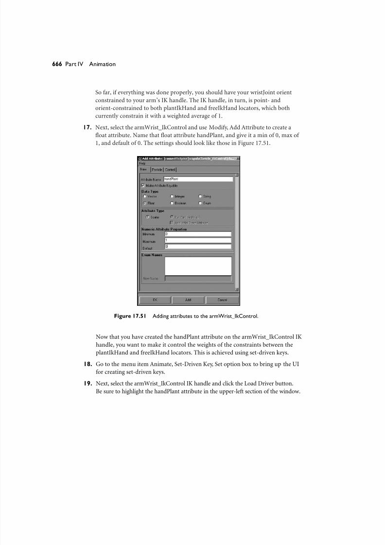
8/7/2019 Riggin 4 Character Anmtn
http://slidepdf.com/reader/full/riggin-4-character-anmtn 58/88
So far, if everything was done properly, you should have your wristJoint orientconstrained to your arm’s IK handle. The IK handle, in turn, is point- and
orient-constrained to both plantIkHand and freeIkHand locators, which both
currently constrain it with a weighted average of 1.
17. Next, select the armWrist_IkControl and use Modify, Add Attribute to create a
float attribute. Name that float attribute handPlant, and give it a min of 0, max of
1, and default of 0. The settings should look like those in Figure 17.51.
666 Part IV Animation
Figure 17.51 Adding attributes to the armWrist_IkControl.
Now that you have created the handPlant attribute on the armWrist_IkControl IK
handle, you want to make it control the weights of the constraints between the
plantIkHand and freeIkHand locators. This is achieved using set-driven keys.
18. Go to the menu item Animate, Set-Driven Key, Set option box to bring up the UI
for creating set-driven keys.
19. Next, select the armWrist_IkControl IK handle and click the Load Driver button.Be sure to highlight the handPlant attribute in the upper-left section of the window.

8/7/2019 Riggin 4 Character Anmtn
http://slidepdf.com/reader/full/riggin-4-character-anmtn 59/88
20. Open the Hypergraph and select the two bottom constraints that are children of thearmWrist_IkControl node (the point and orient constraints that you just finished
creating in Step 16). These should be named armWrist_IkControl_pointConstraint1
and armWrist_IkControl_orientConstraint1. Hold the Shift key and add to the
selection the plantIkHand and freeIkHand nodes. Next, in the Set-Driven Key win-
dow, click Load Driven. Your window should look like Figure 17.52.
667Chapter 17 Rigging Characters for Animation
Figure 17.52 Preparing to use the Set-Driven Key window.
The next few steps are very important for applying the set-driven keys correctly.
21. First, be sure that the armWrist_IkControl IK handle’s handPlant attribute is set
to 0 and is loaded as the driver node/attribute. Also be sure that the node name
armWrist_IkControl is highlighted on the upper left and that the attribute name
handPlant is highlighted on the upper right of the Set-Driven Key window.
22. Now set the attributes on your nodes to the following values:
Driver attribute:
armWrist_IkControl.handPlant: 0
Driven attributes:freeIkHand.visibility: on
plantIkHand.visibility: off
armWrist_IkControl_pointConstraint1.plantIkHandW0: 0
armWrist_IkControl_pointConstraint1.freeIkHandW1: 1

8/7/2019 Riggin 4 Character Anmtn
http://slidepdf.com/reader/full/riggin-4-character-anmtn 60/88
armWrist_IkControl_orientConstraint1.plantIkHandW0: 0armWrist_IkControl_orientConstraint1.freeIkHandW1: 1
23. Now that your attributes are set exactly from the previous list, with your driver
node actively highlighted, go through the driven nodes in the Set-Driven Key win-
dow and, one by one, click each node/attribute in the Driven section. Highlight
each name on the lower left, highlight the attribute that you just set on the lower
right, and hit the Key button. For example, the first node to highlight on the bot-
tom left is the freeIkHand; on the bottom right, it is the attribute visibility. With
both highlighted, hit the Key button. Do this for each node’s attribute that you
previously loaded and set, including each constraint separately (see Figure 17.53).
668 Part IV Animation
Figure 17.53 Using the Set-Driven Key window.
Now that you have hit the Key button for each driven attribute value when
the driver is set to 0, you will set the values for the driven attributes when the
driver is set to 1.
24. Set the following node attribute’s values:
Driver attribute:
armWrist_IkControl.handPlant: 1
Driven attributes:
freeIkHand.visibility: off
plantIkHand.visibility: on
armWrist_IkControl_pointConstraint1.plantIkHandW0: 1
8/7/2019 Riggin 4 Character Anmtn
http://slidepdf.com/reader/full/riggin-4-character-anmtn 61/88
armWrist_IkControl_pointConstraint1.freeIkHandW1: 0armWrist_IkControl_orientConstraint1.plantIkHandW0: 1
armWrist_IkControl_orientConstraint1.freeIkHandW1: 0
25. Finally, repeat the previous step, but using the current values, and set a driven key
on each one of your driven node/attributes. One by one, highlight them in the
Driven section of the Set-Driven Key window; one by one, highlight their attrib-
utes. Then hit the Key button to set the driven node’s attribute key at the current
driver node’s attribute value.
Two locators control the location of the arm’s IK handle as well as the orientation of
the wrist. For the most part, the freeIkHand locator can be used to animate the handwhen it does not need to be planted on something. But now there’s an extra node to
use to plant and orient the hand on a shot-by-shot basis, without ever needing to add
extra controls to the character.When you need the hand to transition from being free
moving to being planted somewhere, simply parent or point-constrain the
plantIkHand onto the object that the hand needs to be stuck to and then animate the
.handPlant attribute over a couple of frames, from 0 to 1. This hides the freeIkHand lo-
cator, which you no longer need to animate, and makes visible the plantIkHand loca-
tor, which you have stuck onto something.
In the next exercise, you will tackle the stretchy arm setup, which includes creating
all the controls, attributes, and node networks involved to make an automatically
stretchy IK arm that will stretch to maintain the distance between the IK handle and
the shoulder. Regardless of whether the location of the shoulder or the location of the
IK handle causes this distance to become greater, the arm will still stretch automatical-
ly. You will also add all the controls needed by an animator to animate this behavior
blended on and off, while still exposing manual controls to scale the length on top of
these controls.
Exercise 17.8 Stretchy Arm Setup
Begin by creating a distance dimension node for the arm. You will do this the same way
you created the distance dimension for the clav to shoulder. This begins the controls
that cause the arm to stretch.
1. Go to Create, Measure Tools, Distance Tool to activate the Distance tool.
669Chapter 17 Rigging Characters for Animation

8/7/2019 Riggin 4 Character Anmtn
http://slidepdf.com/reader/full/riggin-4-character-anmtn 62/88
2. Now click with the mouse once in the general area of the shoulder and again inthe general area of the wrist. You will get two locators, most likely named locator1
and locator2. Rename these locators shoulderPoint for the locator near the shoul-
der, and wristPoint for the locator near the wrist. Also rename the
distanceDimension node armDistance_distanceDimension.
3. Select the shoulderJoint node, Shift+select the shoulderPoint locator, and point-
constrain the locator to the shoulder by using Constrain, Point. Next, point-
constrain the wristPoint locator to the armWrist_IkControl by selecting the
armWrist_IkControl, Shift+selecting the wristPoint locator, and again performing
the menu command Constrain, Point. Finally, select the two locators and the
distanceDimension node, and group them using the Ctrl+g keyboard combina-
tion. Name this new group armDistanceGroup (see Figure 17.54).
670 Part IV Animation
Figure 17.54 Setting up the constraints for the stretchy arm.
4. Parent the armDistanceGroup node under the connectToSpine joint node so that
it is part of the hierarchy that will comprise the arm.
Next, you will create a bunch of math utility nodes to create a node-based expres-
sion network. These nodes were built in Maya traditionally for rendering, but they
are more commonly being used for character rigging as well.

8/7/2019 Riggin 4 Character Anmtn
http://slidepdf.com/reader/full/riggin-4-character-anmtn 63/88
5. Open the Hypershade window by clicking Window, Rendering Editors,Hypershade, and go to the Create, Create New Node menu. This launches the
Create Render Node window. Next, click the tab labeled Utilities and create the fol-
lowing series of nodes (you will create four total utility nodes—see Figure 17.55):
Create three multiplyDivide nodes and rename them armScaleRatio,
autoStretchMultiplier, and armScaleMultiplier.
Create one Condition node and rename it shortenToleranceCondition.
671Chapter 17 Rigging Characters for Animation
Figure 17.55 Setting up the utility nodes for the stretchy arm.
Next, you will create a few attributes that an animator can use to control the
stretchiness of the character’s arms.
6. Select the armWrist_IkControl and load up the Add Attribute window by going to
Modify, Add Attribute.
7. In the Add Attribute window, create three float data type attributes with the fol-
lowing names and settings:
autoStretch (min 0, max 1, default 1)shortenTolerance (min 0, max 1, default 1)
armScale (min 0, max 10, default 1)

8/7/2019 Riggin 4 Character Anmtn
http://slidepdf.com/reader/full/riggin-4-character-anmtn 64/88
Now it is time to get started connecting some attributes to create our stretchy IKarm.
Because you already have the Hypershade window open, you will use it (instead of
the Hypergraph) to make all of your node connections.
8. Choose the Utilities tab from the Hypershade, and select all four of the
new utility nodes that you just created. Shift+add to the selection the
armDistance_distanceDimension node and the armWrist_IkControl node from
either the Hypergraph or the 3D view port. Now, with the current active selection
in the Hypershade, click the menu item Graph, Input and Output Connections.
You get a somewhat disorganized display of nodes. Organize the nodes in your
window so that they are visually lined up similar to the order pictured, to make it
easier to connect the appropriate attributes (see Figure 17.56).
672 Part IV Animation
Figure 17.56 Preparing the utility nodes for the stretchy arm.
9. Holding down the Shift key and the middle mouse button, drag and drop the
distanceDimensionShape node onto the armScaleRatio multiplyDivide node.
Using the Connection Editor, connect the distance attribute to the input1Xattribute of the multiplyDivide node.

8/7/2019 Riggin 4 Character Anmtn
http://slidepdf.com/reader/full/riggin-4-character-anmtn 65/88
10. Now select the armScaleRatio multiplyDivide node that you just connected to, andhit Ctrl+a to launch the Attribute Editor. Change the multiplyDivide node’s opera-
tion mode from Multiply to Divide. Now copy the number from the input1X
channel and paste it into the input2X channel so that you are dividing the current
distance by the original distance.
The node’s output should currently equal 1; as the distance grows, the output will
be a normalized ratio equal to how much the initial distance has scaled (starting
from 1). This output will eventually be the number that you use to drive the scale
of the arm joints, but you will set up a few extra nodes to add a small amount of
logic and control over the stretchiness.
11. Using the Connection Editor window, connect the following attributes to create an
expression-based node network:
The armWrist_IkControl.autoStretch attribute into the
autoStretchMultiplier.input1X attribute
The armScaleRatio.outputX attribute into the autoStretchMultiplier.input2X
attribute (The output of this autoStretchMultiplier node enables you to blend
the stretchy behavior from on to off, and vice versa.)
The autoStretchMultiplier.outputX attribute into the
shortenToleranceCondition.firstTerm attribute
The autoStretchMultiplier.outputX attribute also into the
shortenToleranceCondition.colorIfFalseR attribute
The armWrist_IkControl.shortenTolerance attribute into the
shortenToleranceCondition.secondTerm attribute
The armWrist_IkControl.shortenTolerance also into the
shortenToleranceCondition.colorIfTrueR attribute (The output of the
shortenToleranceCondition node’s outColorR attribute now keeps the arm
from shrinking shorter than the shortenTolerance attribute specifies.)
The shortenToleranceCondition.outColorR attribute into the
armScaleMultiplier.input1X attribute
The armWrist_IkControl.armScale attribute into the
armScaleMultiplier.input2X attribute
12. Next, select the shortenToleranceCondition node and open the Attribute Editor by
hitting Ctrl+a. Change the operation mode of this condition node to Less Than.
673Chapter 17 Rigging Characters for Animation

8/7/2019 Riggin 4 Character Anmtn
http://slidepdf.com/reader/full/riggin-4-character-anmtn 66/88
This condition node keeps the arm from scaling any shorter than what thearmWrist_IkControl.shortenTolerance attribute is set to by making a decision for
you. The logic behind how the condition node works is as follows: If the First
Term is Less Than the Second Term, use Color If True; otherwise, use Color If
False. This output, which goes into the armScaleMultiplier, enables you to manu-
ally stretch the arm longer or shorter by changing this attribute.
All that is left is to connect the output of this scale multiplier to each of the arm
joints (the shoulder and the elbow).
13. Again, using the Connection Editor, connect the armScaleMultiplier.outputX
attribute into both the shoulderJoint.scaleX and elbowJoint.scaleX attributes.
Figure 17.57 shows a Hypershade and Hypergraph Input and Output Connections
view of what your final node network should look like.
674 Part IV Animation
Figure 17.57 A Hypershade and Hypergraph Input and Output
Connections view of what your final node network should look like.
Figure 17.58 shows a Hypergraph Scene Hierarchy view of what your node’s
groupings should look like.

8/7/2019 Riggin 4 Character Anmtn
http://slidepdf.com/reader/full/riggin-4-character-anmtn 67/88
Figure 17.58 A Hypergraph Scene Hierarchy view of what your node’s groupings should look like.
Now spend a few minutes testing the controls and attributes that you just created. Try
moving around the freeIkHand locator while the handPlant attribute on the IK handle
is set to 0. Experiment with your controls to make sure you didn’t miss a step and that
everything is functioning properly. If something seems to be working incorrectly,
go back and retrace your steps to troubleshoot what might have gone wrong. Thiscompleted exercise with all the rigging finished is found in the file
Jerk_ArmSetup_Finished.mb in the CD folder for this chapter.
In the next exercise, you will add the hand to the arm setup and, finally, put in all
the control boxes that the character animator will ultimately use to animate the entire
arm and hand.
Exercise 17.9 Rigging an Advanced Additive Hand and Fingers
Before you start this exercise, take a moment to examine the hierarchy of the hands for
this setup, as in the file Jerk_HandJoints.mb in this chapter’s folder on the CD. Note
that at each knuckle there is an additional joint that is directly on top of the child
knuckle joint. This technique allows for two things. It zeroes out the transforms of the
children knuckles (which will be directly animated), and it also allows for layered ani-
mation on the parent knuckles if this becomes necessary for later shot requirements.
675Chapter 17 Rigging Characters for Animation

8/7/2019 Riggin 4 Character Anmtn
http://slidepdf.com/reader/full/riggin-4-character-anmtn 68/88
Also note that the knuckles have control boxes around them. The technique of using control boxes for the animators to set keys on is a great idea when setting up a
character. Control boxes can be added to a character in many ways; this is covered later
in this chapter. For now,you should know that these control boxes are actually NURBS
curves shape nodes that were made children of the joint’s transform by selecting the
curve shape and then the joint, and using the –shape flag with the parent MEL com-
mand. (See the section in this chapter,“ Hooking Up Control Boxes to Your Character
Rig,” for more information.)
For the hand setup, you want it to be super-easy for an animator to use, as well as
have all the extra controls needed for the animator to hit any hand pose necessary. You
will set up a hand control that will allow the animator to rotate the fingers individually
or together, add a full-finger curl, and add individual controls for each knuckle. You
will use added attributes that are connected to plusMinusAverage nodes, which add to-
gether the attributes that control the rotations of the knuckles.
1. Start by opening the completed previous exercise, which is found in the file
Jerk_ArmSetup_Finished.mb (or, you can start from your own completed file). With
the arm setup file open, import the file Jerk_HandJoints.mb that is on the CD for this
chapter.
2. Select each parent joint node that makes up the fingers and thumb hierarchies.
They are the thumb_1, index_DoubleKnuckle, middle_DoubleKnuckle,
ring_DoubleKnuckle, and pinkyFinger_1 nodes. Parent them directly to the
wristJoint node, and delete the empty handGroup group node that is left.
3. Now select each knuckle control box from the 3D view port, and go to Modify,
Add Attribute. Add the following float data type attributes (just leave the min,max, and default options blank):
fingerFullCurl
fingerMidBend
fingerTipBend
Figure 17.59 shows the result.
You will use the double-jointed knuckle, along with the addition operation of the
plusMinusAverage nodes, to allow the fingerCurl attribute to make the whole fin-
ger bend each joint. This also will cause the finger to flex closed, while still provid-
ing individual control over each joint in each finger so that the animator can pose
the hand very explicitly. For each of the four fingers, you will create two
plusMinusAverage nodes and then connect the same attributes on each finger.
The following steps go through one finger; you should repeat the steps for the rest
of the fingers in the exact same fashion (except for the thumb, which is slightly
different and is covered separately).
676 Part IV Animation
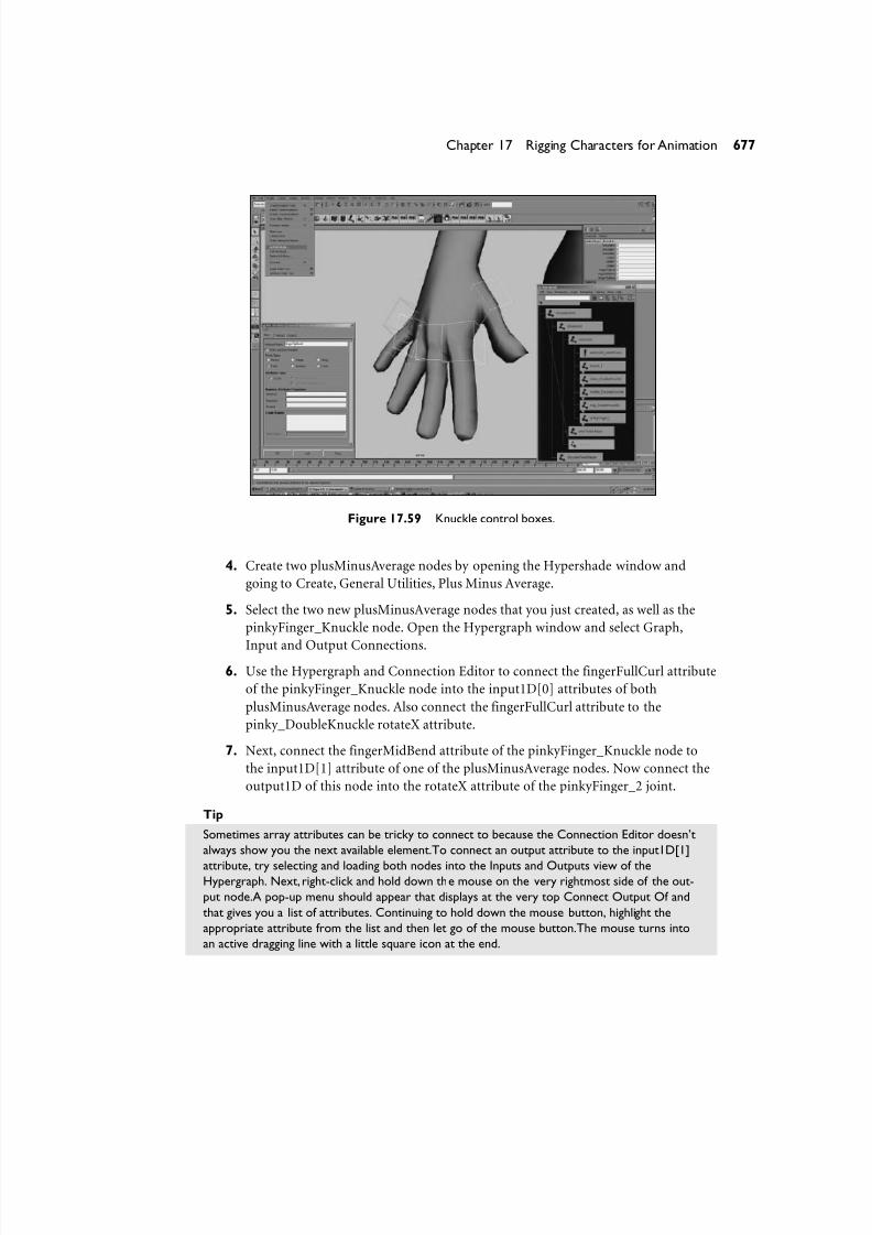
8/7/2019 Riggin 4 Character Anmtn
http://slidepdf.com/reader/full/riggin-4-character-anmtn 69/88
Figure 17.59 Knuckle control boxes.
4. Create two plusMinusAverage nodes by opening the Hypershade window and
going to Create, General Utilities, Plus Minus Average.
5. Select the two new plusMinusAverage nodes that you just created, as well as the
pinkyFinger_Knuckle node. Open the Hypergraph window and select Graph,
Input and Output Connections.6. Use the Hypergraph and Connection Editor to connect the fingerFullCurl attribute
of the pinkyFinger_Knuckle node into the input1D[0] attributes of both
plusMinusAverage nodes. Also connect the fingerFullCurl attribute to the
pinky_DoubleKnuckle rotateX attribute.
7. Next, connect the fingerMidBend attribute of the pinkyFinger_Knuckle node to
the input1D[1] attribute of one of the plusMinusAverage nodes. Now connect the
output1D of this node into the rotateX attribute of the pinkyFinger_2 joint.
Tip
Sometimes array attributes can be tricky to connect to because the Connection Editor doesn’t
always show you the next available element.To connect an output attribute to the input1D[1]
attribute, try selecting and loading both nodes into the Inputs and Outputs view of theHypergraph. Next, right-click and hold down the mouse on the very rightmost side of the out-
put node.A pop-up menu should appear that displays at the very top Connect Output Of and
that gives you a list of attributes. Continuing to hold down the mouse button, highlight the
appropriate attribute from the list and then let go of the mouse button.The mouse turns into
an active dragging line with a little square icon at the end.
677Chapter 17 Rigging Characters for Animation

8/7/2019 Riggin 4 Character Anmtn
http://slidepdf.com/reader/full/riggin-4-character-anmtn 70/88
Now right-click on top of the node that contains the input array attribute, and hold down themouse button.You should see a menu labeled Connect Input Of.While still holding down the
right mouse button on top of your input node, select the appropriate input array attribute.
That’s it—you just made a connection.This technique takes a little practice, but it is really fast
once you get the hang of it.And it takes less effort because you don’t need to load the
Connection Editor just to connect a few attributes.
8. Connect the fingerTipBend attribute of the pinkyFinger_Knuckle node to the
input1D[1] attribute of the other plusMinusAverage node. Now connect the out-
put1D of this node into the rotateX attribute of the pinkyFinger_3 joint.
Figure 17.60 is an example of what the node network looks like for the finger.
678 Part IV Animation
Figure 17.60 This is what the node network looks like for the finger.
Perform steps 2 through 8 for each of the other four fingers.
9. For the thumb, create three plusMinusAverage nodes. Select them along with the
thumb_Knuckle joint, and load them in the Input Output Connections view of
the Hypergraph.
10. Connect (using the Hypergraph and the Connection Editor) the thumb_Knuckle
rotateY and rotateZ attributes directly to control the thumb_1 rotateY and rotateZ
attributes.

8/7/2019 Riggin 4 Character Anmtn
http://slidepdf.com/reader/full/riggin-4-character-anmtn 71/88
11. Connect the fingerFullCurl attribute of the thumb_Knuckle to the input1D[0]attribute of one of the unused plusMinusAverage nodes. Then connect the
fingerMidBend attribute to the input1D[1] attribute of the same
plusMinusAverage node. Now connect the output1D of this plusMinusAverage
into thumb_DoubleKnuckle rotateX.
12. Connect the fingerFullCurl attribute of the thumb_Knuckle to the input1D[0]
attribute of one of the other unused plusMinusAverage nodes. Then connect the
thumb_Knuckle rotateX attribute to the input1D[1] attribute of the same
plusMinusAverage node; connect its output1D into the rotateX of the thumb_1
node.
13. Connect the fingerFullCurl attribute of the thumb_Knuckle to the input1D[0]
attribute of the last unused plusMinusAverage node. Then connect the
fingerTipBend attribute to the input1D[1] attribute of the same plusMinusAverage
node. Now connect the output1D of this plusMinusAverage into the thumb_2
rotateX attribute. Your result should look like Figure 17.61.
679Chapter 17 Rigging Characters for Animation
Figure 17.61 Utility nodes set up for the hand.

8/7/2019 Riggin 4 Character Anmtn
http://slidepdf.com/reader/full/riggin-4-character-anmtn 72/88
This completes the hand setup. For a finished example file of this rig, open the scenefile Jerk_HandSetup_Finished.mb, which is included in this chapter’s folder of the CD.
Hooking Up the Head Skeletal HierarchyFor the head of a character, you can create a separate hierarchy that is point-con-
strained to a locator that is a child of the spine or neck. This leaves the rotational
controls free from the hierarchy and enables the animator to animate them by hand
(see Figure 17.62). You will do this in the next exercise.
680 Part IV Animation
Figure 17.62 IK layout for the head.
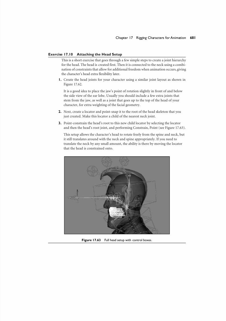
8/7/2019 Riggin 4 Character Anmtn
http://slidepdf.com/reader/full/riggin-4-character-anmtn 73/88
Exercise 17.10 Attaching the Head SetupThis is a short exercise that goes through a few simple steps to create a joint hierarchy
for the head. The head is created first. Then it is connected to the neck using a combi-
nation of constraints that allow for additional freedom when animation occurs, giving
the character’s head extra flexibility later.
1. Create the head joints for your character using a similar joint layout as shown in
Figure 17.62.
It is a good idea to place the jaw’s point of rotation slightly in front of and below
the side view of the ear lobe. Usually you should include a few extra joints that
stem from the jaw, as well as a joint that goes up to the top of the head of your
character, for extra weighting of the facial geometry.
2. Next, create a locator and point-snap it to the root of the head skeleton that youjust created. Make this locator a child of the nearest neck joint.
3. Point-constrain the head’s root to this new child locator by selecting the locator
and then the head’s root joint, and performing Constrain, Point (see Figure 17.63).
This setup allows the character’s head to rotate freely from the spine and neck, but
it still translates around with the neck and spine appropriately. If you need to
translate the neck by any small amount, the ability is there by moving the locator
that the head is constrained onto.
681Chapter 17 Rigging Characters for Animation
Figure 17.63 Full head setup with control boxes.
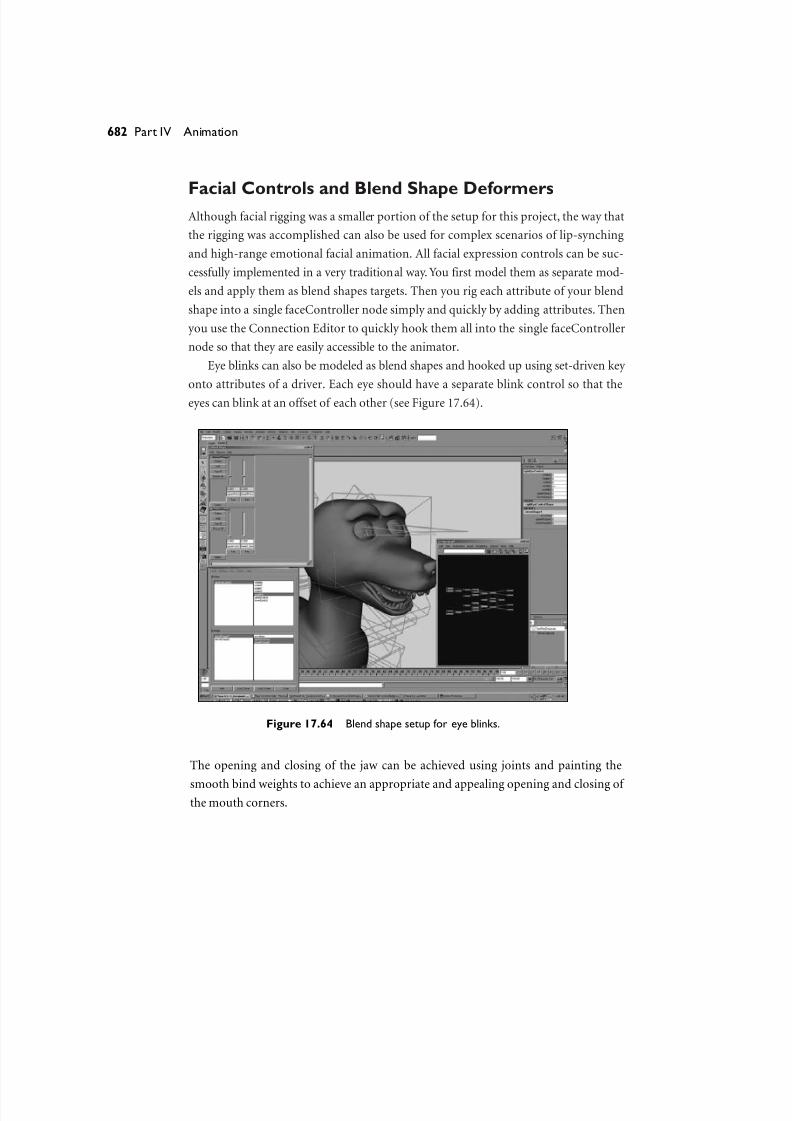
8/7/2019 Riggin 4 Character Anmtn
http://slidepdf.com/reader/full/riggin-4-character-anmtn 74/88
Facial Controls and Blend Shape DeformersAlthough facial rigging was a smaller portion of the setup for this project, the way that
the rigging was accomplished can also be used for complex scenarios of lip-synching
and high-range emotional facial animation. All facial expression controls can be suc-
cessfully implemented in a very traditional way. You first model them as separate mod-
els and apply them as blend shapes targets. Then you rig each attribute of your blend
shape into a single faceController node simply and quickly by adding attributes. Then
you use the Connection Editor to quickly hook them all into the single faceController
node so that they are easily accessible to the animator.
Eye blinks can also be modeled as blend shapes and hooked up using set-driven key
onto attributes of a driver. Each eye should have a separate blink control so that the
eyes can blink at an offset of each other (see Figure 17.64).
682 Part IV Animation
Figure 17.64 Blend shape setup for eye blinks.
The opening and closing of the jaw can be achieved using joints and painting the
smooth bind weights to achieve an appropriate and appealing opening and closing of the mouth corners.

8/7/2019 Riggin 4 Character Anmtn
http://slidepdf.com/reader/full/riggin-4-character-anmtn 75/88
It is important to note that all the blend shapes for the lips must be modeled withthe geometry in the default pose, with the mouth closed, to avoid double transforma-
tions of the jaw being double deformed while opening.
Tip
To create blend shapes for a character that has already been bound to a skeleton, you will
want to be sure of two things:
• Be sure that you are using an exact duplicate of the character’s geometry before it was
bound to the skeleton to begin modeling your blend shapes.
• When you create the blend shape, go into the Advanced tab in the Create Blend Shape
options box and choose the Front of Chain options in the deformation order pull-down
menu. Or, after you create the blend shape, choose Inputs,All Inputs and use the middle
mouse button to drag your blend shape to the bottom of the deformation order list (just
above any tweak nodes there—see Figure 17.65).
683Chapter 17 Rigging Characters for Animation
Figure 17.65 List of history operations window.
Creating Eye Controls
The eye’s “look at” controls were set up simply with two joints for each eye. RPK IK
handles were point- and pole vector–constrained to a locator that is a child of the“look at” control.
The next exercise takes you through this process. Start with a new scene and create
two spheres, evenly placed as your eyeball objects.

8/7/2019 Riggin 4 Character Anmtn
http://slidepdf.com/reader/full/riggin-4-character-anmtn 76/88
Exercise 17.11 Eye SetupBegin by creating the joints for the eyes.
1. Create two joints for each eye.
The crucial aspect of where these joints get placed is that the parent joint (the one
that will control the rotations of the eye) has its location in the exact same loca-
tion of the eye geometry’s pivot. Therefore, it is also extremely important that the
eye be capable of rotating around its own pivot without visibly intersecting any of
the face’s external geometry. In other words, make sure the eyes can look around
correctly by simply rotating around. If the eyes are perfect spheres and are care-
fully placed inside the head, and if the head is modeled correctly around the eyes,
centering the pivot of the eyes should work just fine.
An easy way to make sure your parent joint is in the exact same place as your eye-
ball joint is to turn on handles for the node that should rotate the eyes. You can do
this by selecting the joint and going to Display, Component Display, Selection
Handles. Then use the v key to point-snap the joint directly on top of the location
during creation and layout of the joint.
2. Create two locators, and place each locator directly in front of each eye.
3. Name the joints and the two children locators appropriately according to which
eye they are in front of: leftEyeJoints and leftEyeAim.
4. Next, create an IK handle from the parent joint to the end joint at the end of the
eye.
5. Now select the “look at” locator first and the IK handle second; click Constrain,
Point to point-constrain the IK handle onto the locator.
6. With the same selection active, click Constrain, Pole Vector to pole vector–
constrain the IK handle to the same target.
7. Select the eyeball geometry group. Shift+select the parent eyeball joint, and hit p
to parent the eyeball geometry to the joint (see Figure 17.66).
684 Part IV Animation

8/7/2019 Riggin 4 Character Anmtn
http://slidepdf.com/reader/full/riggin-4-character-anmtn 77/88
Figure 17.66 Parenting the eyeball to the eyeball joint hierarchy.
You can now hook up some parented control boxes to make the eyes look around. You
can add an additional parent to the aim locator that is point-constrained to the loca-
tion of the eyes. An animator can use this to have FK-style rotations and then actually
translate the locator to have the IK style look at control as well.
This technique involves several really cool things.First, you will not get flipping be-
cause you will have control over the IK handle’s rotate plane much better than a mere
aim constrain could provide. Second, you can actually bind those joints that are rotat-
ing the eyes to the face geometry.When you weight the character,you will want to care-
fully distribute the weighting of the eye joints just around the lids of the character,
somewhere between .2 and .4, so that the fleshy area around the eyes actually deforms
subtlety enough when his eyes look around.
The Hair of the JerkFor the hair of The Jerk, the overlapping action rig setup was used (loaded straight
from the finished example file from Chapter 13, “Making Advanced Connections”).
This was simply imported from the completed file from Chapter 13,
chapter13_OverlappingAction_finished.mb, and then was translated, rotated, and
scaled into place using the TRANS_ROTATE_SCALE_MATRIX node. Then the
mainAttachNode was constrained to the end of the head hierarchy to attach it to the
main skeleton. See Chapter 13 for a detailed step-by-step tutorial on how to create this
dynamically driven floppy IK setup.
685Chapter 17 Rigging Characters for Animation
8/7/2019 Riggin 4 Character Anmtn
http://slidepdf.com/reader/full/riggin-4-character-anmtn 78/88
NoteIf you do not want the dynamics mode of this rig during actual animation testing, you can turn
the dynamicFlopOnOff and addMoreFlopiness attributes found on the FloppyChainContoller
locator node to 0 until the actual playblasted animation occurs.Then you can begin testing how
high you want to set these attributes. Note that because this portion of the rig is using soft
body particle dynamics, it is necessary to start the animation at least 10 to 15 frames earlier so
that the dynamics get a chance to calculate their initial position correctly.
Smooth Binding Proxy Geometry
The characters were modeled using subdivision surfaces in Maya, but when it came to
production, we chose to convert our properly modeled sub-d meshes into medium-resolution polygon meshes for the purposes of our rendering pipeline going out to
Mental Ray.We were also fortunate enough to not need to deal with the hassle of bind-
ing Maya’s sub-d surfaces or doing any deformations on sub-d geometry at all because
we had a pure polygon conversion before skinning occurred. I strongly recommend
doing things this way, unless there is a strong reason to not to. The level of simplifica-
tion on a geometric level becomes a real time saver and improves the quality of your
final result.
This might not be the case for some productions using Maya, though. Because sub-
division surfaces are going for a full-blown implementation in Maya, I have included
the workflow that is involved with rigging a character that is actually built from Maya’s
native subdiv mesh node. The following exercise was not necessarily used for our pro-
duction, but it is an important step to take if you are planning to skin a subdivision
mesh in Maya.
The basic premise for the workflow is this: We do not want to bind the Maya subdi-
vision surface itself to the joint’s skinCluster because it will be much too slow to
deform or to paint weights onto. The difficulty of working with the model is truly over-
whelming when compared with simply binding the polygon control mesh shape node.
You will bind only the joints that need to deform the character by implicitly selecting
them and then selecting the polygon control mesh shape node, instead of binding
directly the subdivision surface.
686 Part IV Animation

8/7/2019 Riggin 4 Character Anmtn
http://slidepdf.com/reader/full/riggin-4-character-anmtn 79/88
Exercise 17.12 How to Bind a Subdiv Mesh’s Polygon Proxy Control MeshThis exercise was written to work with any character as a general workflow tutorial.
Therefore, it is not file-specific.You will simply need to start with a scene that contains
any Maya subdivision surface geometry and some joints to bound the geometry onto.
1. Go to your current 3D view panel. Under the Show menu, turn off everything except
joints. This makes it easier to see and select only joints.
2. Carefully select only the joints that are important for the character to deform.
This means that anywhere there are overlapping or point-constrained joints, select
only the single joint that should be causing the deformations. Never select two
joints that are overlapping (double joints). You also usually don’t need to select the
tips of the joint hierarchies. Keep the Hypergraph open to make sure you areselecting only the joints you need. The fewer joints you select, the fewer you will
have to paint weights for later.
3. When you have made sure your selection is correct, save a quick-select set by going
to Create, Sets, Quick Select Set. Call your new set bindJoints. This is just a way of
saving a selection so that you can go back and select it again later.
4. Now select the subdivision character and open the Hypergraph window. To select
the polygon control mesh, you must be in Scene Hierarchy mode of the
Hypergraph. Turn on Options, Display, Shape Nodes by making sure there is a
check box next to it in the menu window.
5. Next, you should see two shape nodes. One is a subdiv shape that is being fed its
data by a polyToSubdiv node (which you can see if you select it and click Graph,Input and Output Connections). Below it is another shape node, which is a poly-
gon mesh shape. The polygon mesh shape node is your poly control cage (as seen
in Figure 17.67).
You can select the polygon proxy control mesh of your native Maya subdivision
geometry by viewing the shape nodes, as previously stated. Or, you can find it in
the tangled node network that shows up in the Input/Output Connections view of
the Hypergraph. Or, you can use a quick MEL command by selecting it in the
View window and executing the following line in the Script Editor window:
select –r 'listRelatives -c -type mesh';
NoteIf your subdiv surface is not in polyProxy mode, you will need to switch it to this mode before
any of this will appear. Select your surface and go to Subdiv Surfaces, Polygon Proxy Mode.
687Chapter 17 Rigging Characters for Animation
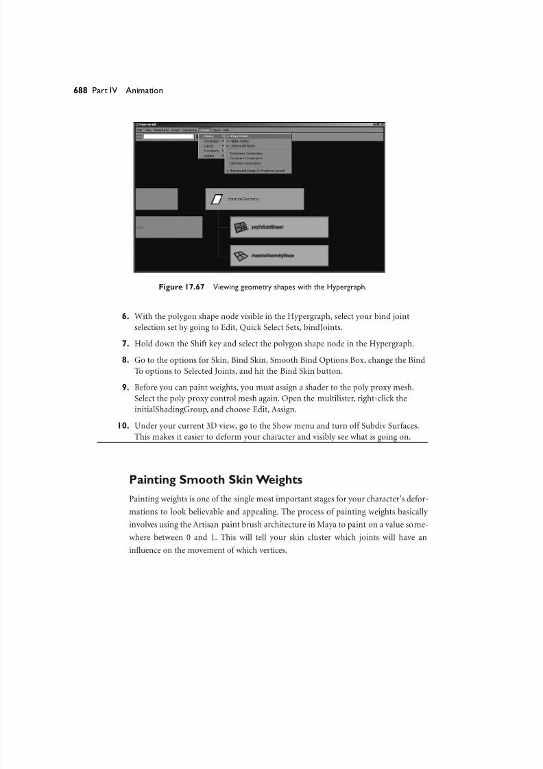
8/7/2019 Riggin 4 Character Anmtn
http://slidepdf.com/reader/full/riggin-4-character-anmtn 80/88
Figure 17.67 Viewing geometry shapes with the Hypergraph.
6. With the polygon shape node visible in the Hypergraph, select your bind joint
selection set by going to Edit, Quick Select Sets, bindJoints.
7. Hold down the Shift key and select the polygon shape node in the Hypergraph.
8. Go to the options for Skin, Bind Skin, Smooth Bind Options Box, change the Bind
To options to Selected Joints, and hit the Bind Skin button.
9. Before you can paint weights, you must assign a shader to the poly proxy mesh.
Select the poly proxy control mesh again. Open the multilister, right-click the
initialShadingGroup, and choose Edit, Assign.
10. Under your current 3D view, go to the Show menu and turn off Subdiv Surfaces.
This makes it easier to deform your character and visibly see what is going on.
Painting Smooth Skin Weights
Painting weights is one of the single most important stages for your character’s defor-
mations to look believable and appealing. The process of painting weights basically
involves using the Artisan paint brush architecture in Maya to paint on a value some-
where between 0 and 1. This will tell your skin cluster which joints will have aninfluence on the movement of which vertices.
688 Part IV Animation
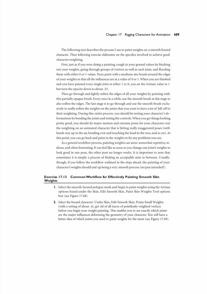
8/7/2019 Riggin 4 Character Anmtn
http://slidepdf.com/reader/full/riggin-4-character-anmtn 81/88
The following text describes the process I use to paint weights on a smooth boundcharacter. Then following exercise elaborates on the specifics involved to achieve good
character weighting.
First, just as if you were doing a painting, rough in your general values by blocking
out your weights, going through groups of vertices as well as each joint, and flooding
them with either 0 or 1 values. Next,paint with a medium-size brush around the edges
of your weights so that all the influences are at a value of 0 or 1. When you are finished
and you have painted every single joint at either 1 or 0, you set the Artisan value to 1
but turn the opacity down to about .33.
Then go through and lightly soften the edges of all your weights by painting with
this partially opaque brush. Every once in a while, use the smooth brush at this stage to
also soften the edges. The last stage is to go through and use the smooth brush exclu-
sively to really soften the weights on the joints that you want to have a lot of fall-off to
their weighting. During this entire process, you should be testing your character’s de-
formations by bending the joints and testing the controls. When you get things looking
pretty good, you should do major motion and extreme poses for your character; test
the weighting on an animated character that is hitting really exaggerated poses (with
hands way up in the air, bending over and touching the head to the toes, and so on). At
this point, you can go back and paint in the weights to fix any problems you see.
As a general workflow process, painting weights can seem somewhat repetitive, te-
dious, and often frustrating. It can feel like as soon as you change one joint’s weights to
look good in one pose, the other pose no longer works. It is important to note that
sometimes it is simply a process of finding an acceptable state in between. Usually,
though, if you follow the workflow outlined in the steps ahead, the painting of your
character’s weights should end up being a very smooth process (no pun intended!).
Exercise 17.13 Common Workflow for Effectively Painting Smooth SkinWeights
1. Select the smooth-bound polygon mesh and begin to paint weights using the Artisan
options found under the Skin, Edit Smooth Skin, Paint Skin Weights Tool options
box (see Figure 17.68).
2. Select the bound character. Under Skin, Edit Smooth Skin, Prune Small Weights
(with a setting of about .4), get rid of all traces of pointlessly weighted verticesbefore you begin your weight painting. This enables you to see exactly which joints
are the major influences deforming the geometry of your character. You will have a
better idea of which joints you need to paint weights for the most (see Figure 17.69).
689Chapter 17 Rigging Characters for Animation
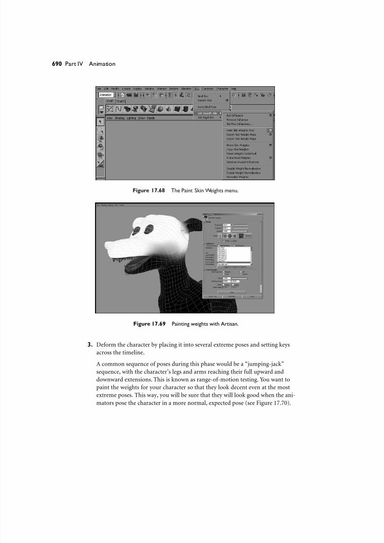
8/7/2019 Riggin 4 Character Anmtn
http://slidepdf.com/reader/full/riggin-4-character-anmtn 82/88
Figure 17.68 The Paint Skin Weights menu.
690 Part IV Animation
Figure 17.69 Painting weights with Artisan.
3. Deform the character by placing it into several extreme poses and setting keys
across the timeline.
A common sequence of poses during this phase would be a “jumping-jack”
sequence, with the character’s legs and arms reaching their full upward and
downward extensions. This is known as range-of-motion testing. You want topaint the weights for your character so that they look decent even at the most
extreme poses. This way, you will be sure that they will look good when the ani-
mators pose the character in a more normal, expected pose (see Figure 17.70).
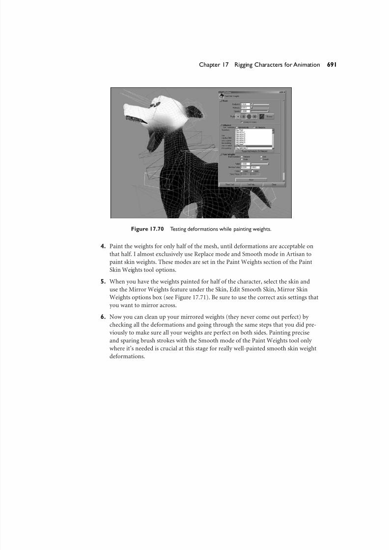
8/7/2019 Riggin 4 Character Anmtn
http://slidepdf.com/reader/full/riggin-4-character-anmtn 83/88
Figure 17.70 Testing deformations while painting weights.
4. Paint the weights for only half of the mesh, until deformations are acceptable on
that half. I almost exclusively use Replace mode and Smooth mode in Artisan to
paint skin weights. These modes are set in the Paint Weights section of the Paint
Skin Weights tool options.
5. When you have the weights painted for half of the character, select the skin and
use the Mirror Weights feature under the Skin, Edit Smooth Skin, Mirror SkinWeights options box (see Figure 17.71). Be sure to use the correct axis settings that
you want to mirror across.
6. Now you can clean up your mirrored weights (they never come out perfect) by
checking all the deformations and going through the same steps that you did pre-
viously to make sure all your weights are perfect on both sides. Painting precise
and sparing brush strokes with the Smooth mode of the Paint Weights tool only
where it’s needed is crucial at this stage for really well-painted smooth skin weight
deformations.
691Chapter 17 Rigging Characters for Animation

8/7/2019 Riggin 4 Character Anmtn
http://slidepdf.com/reader/full/riggin-4-character-anmtn 84/88
Figure 17.71 Use the Mirror Weights feature to create your mirrored weights.
692 Part IV Animation

8/7/2019 Riggin 4 Character Anmtn
http://slidepdf.com/reader/full/riggin-4-character-anmtn 85/88
TipUse the Toggle Hold Weights on Selected button in the Paint Weights window to keep a joint’s
weights from changing after you have painted them (see Figure 17.72).
693Chapter 17 Rigging Characters for Animation
Figure 17.72 Using Toggle Hold Weights.
Paint Weights Using per-Vertex Selections
You can use the Skin, Edit Smooth Skin, Paint Skin Weights tool on a per-vertex level
as well as an entire object level. Many people are not aware that you actually can use
the Paint Weights tool on a per-vertex level by selecting the vertices and loading the
paint weights tool.This is extremely useful when you first start painting the weights on
your character and you are trying to lay out your initial weights, or when you are try-
ing to “point-tweak” certain vertices and leave others alone. Select the vertices whose
weights you want to change, and use the Flood button to flood those vertices in
Replace mode with a value of 1; this is a great first step at very quickly roughing inyour character’s weights. You can then go in and use low opacity in Replace mode with
a value of 1, as well as Smooth mode with flooding, to really disperse the gradual
fall-offs of your joints’ weighting.
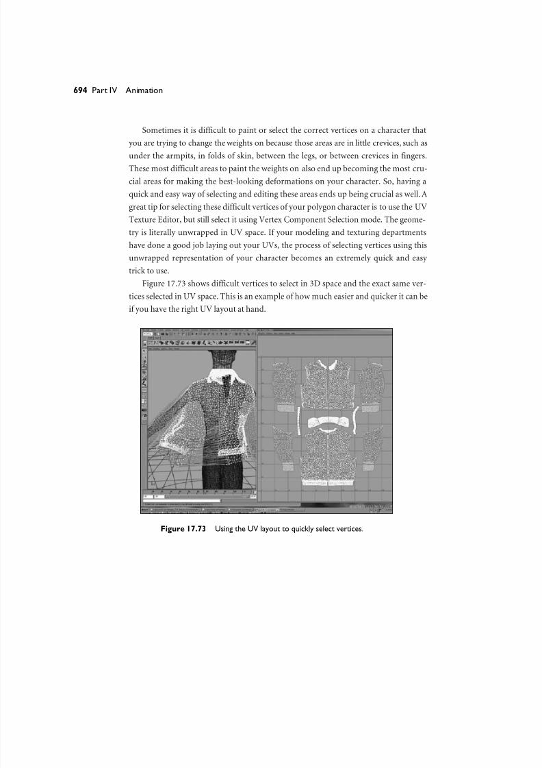
8/7/2019 Riggin 4 Character Anmtn
http://slidepdf.com/reader/full/riggin-4-character-anmtn 86/88
Sometimes it is difficult to paint or select the correct vertices on a character thatyou are trying to change the weights on because those areas are in little crevices, such as
under the armpits, in folds of skin, between the legs, or between crevices in fingers.
These most difficult areas to paint the weights on also end up becoming the most cru-
cial areas for making the best-looking deformations on your character. So, having a
quick and easy way of selecting and editing these areas ends up being crucial as well. A
great tip for selecting these difficult vertices of your polygon character is to use the UV
Texture Editor, but still select it using Vertex Component Selection mode. The geome-
try is literally unwrapped in UV space. If your modeling and texturing departments
have done a good job laying out your UVs, the process of selecting vertices using this
unwrapped representation of your character becomes an extremely quick and easy
trick to use.
Figure 17.73 shows difficult vertices to select in 3D space and the exact same ver-
tices selected in UV space. This is an example of how much easier and quicker it can be
if you have the right UV layout at hand.
694 Part IV Animation
Figure 17.73 Using the UV layout to quickly select vertices.
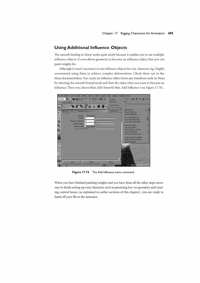
8/7/2019 Riggin 4 Character Anmtn
http://slidepdf.com/reader/full/riggin-4-character-anmtn 87/88
Using Additional Influence ObjectsThe smooth binding in Maya works quite nicely because it enables you to use multiple
influence objects. It even allows geometry to become an influence object that you can
paint weights for.
Although it wasn’t necessary to use influence objects for our character rig, I highly
recommend using them to achieve complex deformations. Check them out in the
Maya documentation. You create an influence object from any transform node in Maya
by selecting the smooth bound mesh and then the object that you want to become an
influence.Then you choose Skin, Edit Smooth Skin, Add Influence (see Figure 17.74).
695Chapter 17 Rigging Characters for Animation
Figure 17.74 The Add Influence menu command.
When you have finished painting weights and you have done all the other steps neces-
sary to finish setting up your character, such as parenting low-res geometry and creat-
ing control boxes (as explained in earlier sections of this chapter), you are ready to
hand off your file to the animator.
8/7/2019 Riggin 4 Character Anmtn
http://slidepdf.com/reader/full/riggin-4-character-anmtn 88/88
SummaryCharacter rigging can be a very fun and interesting process. The one thing to remem-
ber about this entire process, though, is that it will always be a collaboration between
you and other teams. The way that the file is set up, as well as the controls there, will
ultimately be used by the animator; thus, they need to be easily understood and con-
trollable. The deformations of the character will ultimately change the shape and
nature of the character’s model and must therefore stay true to the design and style in
which the character was originally modeled. The character that you set up must even-
tually be textured, lit, and rendered, so it absolutely must not have geometric problems
such as bad normals or bad UVs when you bind it to the skeleton. The difficult part in
setting up a character is being able to systematically take all of this into consideration,
with the final goal being a stable character whose transformation space has been
manipulated to offer full control to the animator.
Character animation is a long and difficult process, and the capability to have the
character react in a desirable and predictable way is the most valuable thing that can be
achieved. To make the character’s controls and deformations predictable, and to give
the character the capability to be textured, lit, and rendered are all vital in their own
ways. The process of character animation will continue to become more simplified—
and, therefore, capable of more sophistication—as time goes by. The same can be said
of the techniques to rig a good character that is capable of achieving more types of
motion. Always remember that, much like a puppet, there is a human behind the
controls of your character breathing the appeal of artificial life into its computer-generated soul.
696 Part IV Animation