rifton tram (k310) product manual
TRANSCRIPT

K310 & K320 Product Manual
K310
, K320
Pro
du
ct Man
ual
R TM

2© 2018 Rifton Equipment
ContentsSafety messages 3-4
Key for users and important information 5
Recommended use and user and item dimensions 6
Check your order and basic components 7
Initial assembly and directions for use 8
Battery box 9-10
Base frame expansion 11
Body support system 12
Accessories
Scale 13-14
Gait tracker 15
Thigh straps, pelvic support, hip positioner and swivel lock 16
Forearm supports 17-18
Arm platforms 19
Switch pole 20
Operation and transfers 20-22
Battery charger 23
Troubleshooting 24
Technical data 25
Maintenance and cleaning 26
Warranty, materials and user modifi cations 27

3
• Thoroughly read and understand the information in this product manual before attempting to use this product. If the procedures and instructions in this product manual are not followed, serious injury or death could occur.
• The TRAM may not be appropriate for all clients. The client’s therapist or physician should assess the appropriateness and safety of the TRAM for each user. For example:
○ The TRAM must only be used for clients who meet the weight and height limits specifi ed in this manual.
○ Clients will experience some pressure to soft tissues when lifted with the TRAM. It may not be appropriate for individuals with fragile skin.
• The TRAM should be operated only by and under the direct supervision of a qualifi ed caregiver who has reviewed and understands this manual.
• To prevent falls and injuries:
○ Do not use the TRAM on rough or uneven terrain, around swimming pools or near stairways.
○ Stop lifting immediately if the body support system slides up under the armpits while lifting. This may be caused by slippery outer clothing, a client with low muscle tone or a body shape and size that is inappropriate for the TRAM.
○ Lift the client no higher than is necessary to perform the intended transfer.
○ Always retract the base legs when maneuvering the TRAM while it is supporting a client in the seated posture; expand the base only when necessary.
○ When using the TRAM for walking support, the base frame should be expanded to increase sideways stability if required by the condition or stature of a particular client; the caregiver must make this judgment on an individual basis.
○ Never leave a client unattended in the TRAM.
○ Ensure the use of straps and supports at all times. Straps and supports are provided for the safety of the user and must be carefully adjusted for comfort and security.
○ The TRAM may be equipped with a non-removable back belt with a single safety buckle, or a removable back belt with two safety buckles. Always ensure that the back belt is in place and that both release tabs on all buckles are fully latched before initiating a lift or transfer.
○ When the TRAM is used in the posterior confi guration, with the client facing rearward in the device, the client can access the back belt safety buckle. The TRAM should not be used in the posterior confi guration with clients of unreliable judgment who may unintentionally release the safety buckle while supported by the device. The caregiver must assess whether posterior use is appropriate for an individual client.
WARNING

4
○ For safe use of the TRAM, prior to initiating a transfer, move the origin and destination of the transfer as close to each other as possible. For example: a client who is to be transferred from a wheelchair to a toilet should be wheeled close to the toilet prior to lifting to minimize time spent in transfer. Never use the TRAM for long distance transport of a lifted client.
• Using straps, trays, or supports to restrict a client’s movement is considered behavioral restraint. Rifton products are not intended for this use.
• This product is intended for indoor use only and must not be used in or around water other than for bathing and shower transfers in accordance with instructions provided.
• To avoid pinching or crushing:
○ Ensure that all hands and feet are clear of the vertical lifting column before activating the up/down switch.
○ Ensure that all hands and feet are clear of the base frame expansion system and the base legs before expanding or retracting the base.
• To prevent head and neck injury, never use the TRAM to lift a client within a vertically confi ned space such as inside a vehicle; always check that adequate head clearance exists before initiating a lift or transfer.
• Never use a broken or damaged TRAM. Regular maintenance in accordance with this manual is necessary for safe use of the TRAM.
WARNING

5
IMPORTANTPlease save this product manual for future reference. Additional copies are available at http://www.rifton.com/customer-service/product-manuals.
Key for usersUse this key to determine which sections of this product manual apply to you.
Technical Users For professionals who order and set up Rifton products.
Home Users For care-givers who use Rifton products on a regular basis.
Maintenance Personnel For anyone who is responsible for service or re-ordering of Rifton products and parts.
6
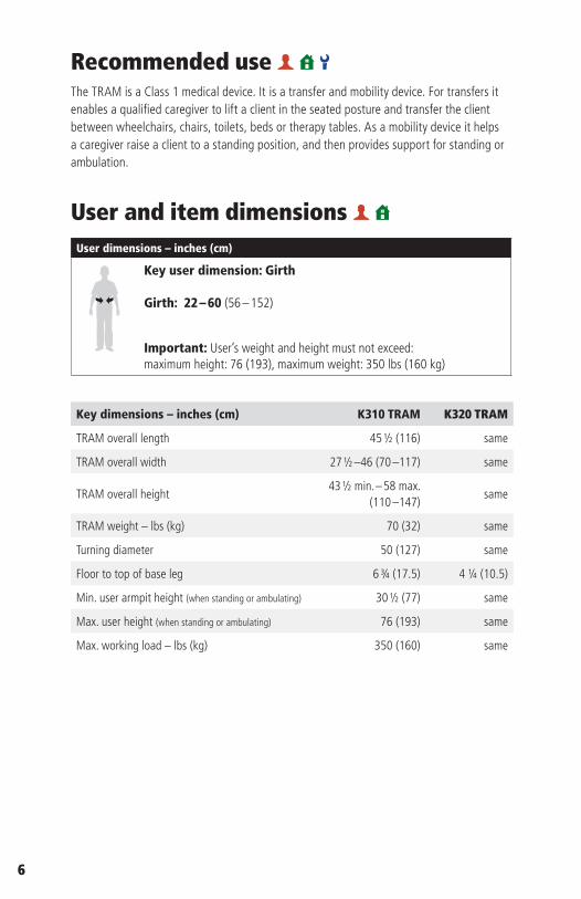
Recommended use The TRAM is a Class 1 medical device. It is a transfer and mobility device. For transfers it enables a qualifi ed caregiver to lift a client in the seated posture and transfer the client between wheelchairs, chairs, toilets, beds or therapy tables. As a mobility device it helps a caregiver raise a client to a standing position, and then provides support for standing or ambulation.
User and item dimensions User dimensions – inches (cm)
Key user dimension: Girth
Girth: 22 – 60 (56 – 152)
Important: User’s weight and height must not exceed:maximum height: 76 (193), maximum weight: 350 lbs (160 kg)
Key dimensions – inches (cm) K310 TRAM K320 TRAM
TRAM overall length 45 ½ (116) same
TRAM overall width 27 ½ – 46 (70 – 117) same
TRAM overall height43 ½ min. – 58 max.
(110 – 147)same
TRAM weight – lbs (kg) 70 (32) same
Turning diameter 50 (127) same
Floor to top of base leg 6 ¾ (17.5) 4 ¼ (10.5)
Min. user armpit height (when standing or ambulating) 30 ½ (77) same
Max. user height (when standing or ambulating) 76 (193) same
Max. working load – lbs (kg) 350 (160) same

7
Check your order Every TRAM comes with a front handle, a battery, a battery charger, a Rifton accessories tote and a scale if ordered. All other accessories are retrofi ttable and can be added later if desired.
Please check that your TRAM has been outfi tted as you ordered it. The TRAM requires some assembly before use. Please follow the instructions included in this manual to ensure that it is assembled and used correctly.
If your shipment is incomplete or in any way damaged on arrival, please call Customer Service, 800.571.8198.
Basic item Inspection
Check daily for damage or wear to the TRAM.
Rear caster
Up/down switch
Scale (optional)
Body support system
Front caster(with brake)
Battery box
Expansion handle
Base legs
Vertical lifting
column
Electronic actuator
Front handle
8
Initial assembly instructions
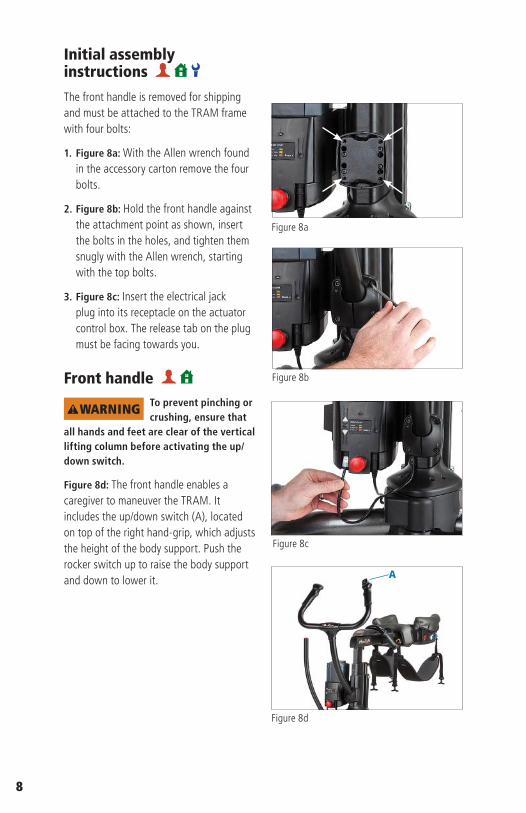
The front handle is removed for shipping and must be attached to the TRAM frame with four bolts:
1. Figure 8a: With the Allen wrench found in the accessory carton remove the four bolts.
2. Figure 8b: Hold the front handle against the attachment point as shown, insert the bolts in the holes, and tighten them snugly with the Allen wrench, starting with the top bolts.
3. Figure 8c: Insert the electrical jack plug into its receptacle on the actuator control box. The release tab on the plug must be facing towards you.
Front handle To prevent pinching or crushing, ensure that
all hands and feet are clear of the vertical lifting column before activating the up/down switch.
Figure 8d: The front handle enables a caregiver to maneuver the TRAM. It includes the up/down switch (A), located on top of the right hand-grip, which adjusts the height of the body support. Push the rocker switch up to raise the body support and down to lower it.
WARNING
Figure 8a
Figure 8b
Figure 8c
Figure 8d
AA

9
WARNING
Battery Box To prevent inadvertent operation of the
up/down switch when the TRAM is not in use, press the E-Stop button (A) to disconnect the battery.
Figure 9a: The battery box houses the microprocessor and rechargeable battery which power and control the TRAM’s electric actuator. Up/down arrows (B) on the battery box control the TRAM’s vertical movement.
Figure 9b: To insert the battery, slide it into the battery box, then push the battery back until it clicks into place. To remove it, squeeze the lever on the back and lift it out.
To prevent long-term battery damage, remove
the battery from the battery box and place it in the charger every night, even if the battery level indicator is still green.
Battery level indicator
To preventinjury:
• Charge or change the battery immediately if the battery level light turns red; do not attempt further lifts or transfers with a red light.
• Prior to every use of the TRAM, activate the up/down button to turn on the battery level light, and verify that the light is green. If it is not, change or charge the battery.
Figure 9c: The battery level light indicates the charge remaining in the battery. A green light means the charge level is adequate for use, yellow indicates that the battery should be charged soon, and red indicates a very low charge. An audible beep indicates that the battery is entirely
NOTICE
Figure 9a
Figure 9b
Figure 9c
CAUTION
AA
BB
10
depleted. A fully charged battery will give approximately 70 complete lift cycles.
To prevent damage to the battery, charge it when the light turns yellow. The indicator light will extinguish 10 minutes after the last activation of the up/down switch. It will turn on again if the up/down switch is used or if a battery is inserted into the battery box.
If the battery level becomes critically low,
indicated by the battery level light turning red, the microprocessor will disable the up/down switch. However, the emergency lowering button will continue to function.
The emergency lowering button will continue to function even if the battery level has dropped below the threshold for operation of the up/down switch. It overrides all other inputs.
To prevent injury, all caregivers should
become familiar with the location and operation of the emergency stop button and the emergency lowering button before using the TRAM.
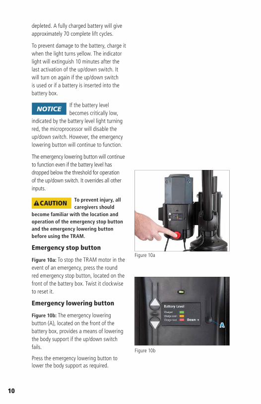
Emergency stop button
Figure 10a: To stop the TRAM motor in the event of an emergency, press the round red emergency stop button, located on the front of the battery box. Twist it clockwise to reset it.
Emergency lowering button
Figure 10b: The emergency lowering button (A), located on the front of the battery box, provides a means of lowering the body support if the up/down switch fails.
Press the emergency lowering button to lower the body support as required.
NOTICE
CAUTION
Figure 10a
Figure 10b
AA

11
Base frame expansion system
To avoid injury, ensure that all hands and feet
are clear of the expansion handle and the base legs before expanding or retracting the base.
Figure 11a: The base frame expansion system adjusts the width of the base frame from 27½”– 40” (70 cm – 102 cm). It expands so that clients can be lifted from wide chairs and wheelchairs, and retracts for maneuverability, and to enable the TRAM to pass through narrow doorways.
Swing the expansion handle to the right to expand the frame, and to the left to close it.
WARNING
Figure 11a
Tip: Disengage swivel locks prior to moving the expansion handle.

12
To avoid injury, never operate the TRAM
without the back belt in place. Always ensure that both release tabs on all buckles are fully latched before initiating
a lift or transfer.
Figure 12a: The TRAM’s body support system includes the body support pads, patient hand grips, ring clips, and the back belt and buckle.
Figure 12b: The back belt has a dual action safety buckle to prevent accidental release. Press the two release tabs simultaneously to release.
Figure 12c: There is also a removable back belt available with a clip at both ends for easy removal and sanitation. To attach it, fi rst clip the non-adjustable end of the back belt into the buckle on the client’s right, with the silver slider facing out. Then clip the adjustable end of the strap on the left to secure client.
The following can also be attached to the body support system, depending on how the TRAM is to be used:
• Thigh straps (see fi gure 16a, and p. 21 for use)
• Pelvic support (see fi gure 16b, and p. 22 for use)
• Forearm supports (see pp. 17 – 18)
• Arm platforms (see p. 19)
Figure 12a
Figure 12b
Body support system
WARNING
Figure 12c
13
Accessories
Scale
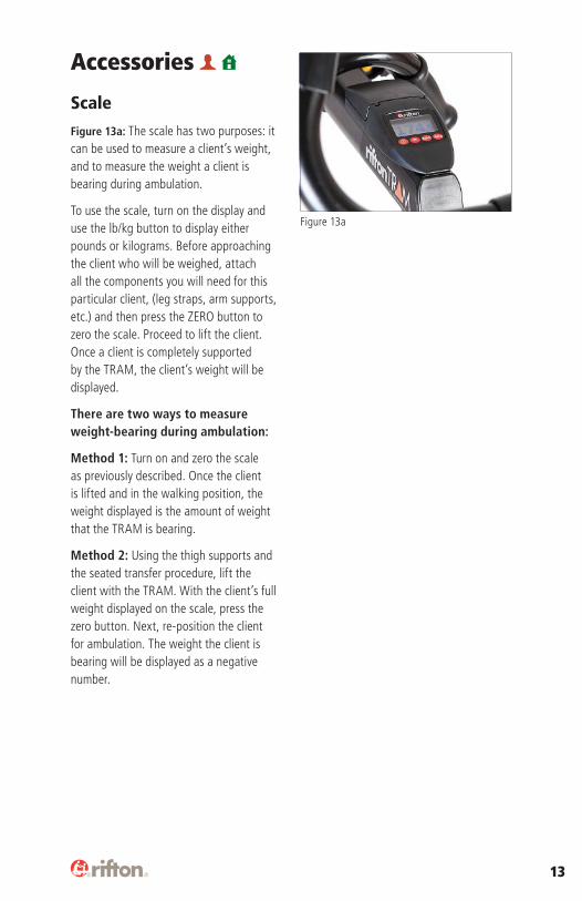
Figure 13a: The scale has two purposes: it can be used to measure a client’s weight, and to measure the weight a client is bearing during ambulation.
To use the scale, turn on the display and use the lb/kg button to display either pounds or kilograms. Before approaching the client who will be weighed, attach all the components you will need for this particular client, (leg straps, arm supports, etc.) and then press the ZERO button to zero the scale. Proceed to lift the client. Once a client is completely supported by the TRAM, the client’s weight will be displayed.
There are two ways to measure weight-bearing during ambulation:
Method 1: Turn on and zero the scale as previously described. Once the client is lifted and in the walking position, the weight displayed is the amount of weight that the TRAM is bearing.
Method 2: Using the thigh supports and the seated transfer procedure, lift the client with the TRAM. With the client’s full weight displayed on the scale, press the zero button. Next, re-position the client for ambulation. The weight the client is bearing will be displayed as a negative number.
Figure 13a

14
Figure 14a: To replace the scale batteries, push outward on the small tab at the rear of the scale housing and lift the battery cover (a small, fl at head screwdriver inserted into the slot at the back of the lid may be used to gently pry it up). Insert fresh AA Alkaline batteries; the cells must be oriented as shown by the inscription in each battery receptacle.
Scale Information
• To obtain an accurate weight measurement, the client must be lifted clear of all weight-bearing surfaces, and the feet or legs must not be in contact with the base frame of the TRAM.
• The scale uses four AA Alkaline batteries. The battery life is approximately 100 hours of continuous use, or approximately 500 weight recordings.
• The scale will automatically turn off if it does not sense a change in weight for more than 10 minutes.
• The scale is accurate to one percent if used correctly.
• Rifton recommends that the scale be calibrated by a qualifi ed technician at three to fi ve year intervals, depending on frequency of use. For instructions on service and calibration, please contact Rifton customer service.
Figure 14a

15
Gait Tracker
Figure 15a: The Gait Tracker app allows data from the TRAM scale to be displayed on mobile phones and tablets via a Bluetooth connection. The app has two primary functions.
1. It displays the weight measured by the scale, averaged over a 10 second interval for smoothness.
2. It calculates the average weight on the TRAM over the course of a gait training session. This value can be used to record and track a client’s weight bearing capability over time.
To use the Gait Tracker app:
Figures 15b and 15c:
1. Install the app on your phone or tablet (currently available only for iOS devices).
2. Activate Bluetooth on the scale by pressing the “BT” button (A).
3. Open the Gait Tracker app on your mobile device. Your device will pair with the scale when you open the app.
4. Press “start” on the app when you are ready to begin the gait training session.
5. Use the “pause” and “resume” commands as needed until the session is over.
6. Before pressing the “reset” button at the end of the session, be sure to make an external record of the session average if needed for tracking purposes. Pressing “reset” will clear all stored data from the app.
Figure 15d: To provide a client with access to the scale data, a phone may also be mounted on the client handlebar using a phone mount for a bicycle handlebar.
Figure 15a
Figure 15b
Figure 15c
AA
Figure 15d

16
Thigh strapsFigure 16a: Thigh straps are used to make seated transfers. Choose either narrow (5”) or wide (7”), depending on the needs of your client. Additional straps can be purchased for individual clients.
Pelvic supportFigure 16b: The pelvic support is used for sit-to-stand transfers and supported ambulation. It is attached by hooking the rings to the color-coded clips of the body support system. Note that the pelvic support may fi t the patient best when the straps are crossed.
Hip positionerFigure 16c: The hip positioner is used to encourage optimum pelvic positioning during gait training. It has an optional pad for comfort. It is attached by hooking the back rings onto the grey clips of the body support system and the front rings onto two of the remaining four clips (including the yellow ones in the front). Adjust the four straps for further positioning.
Caster swivel lockThe swivel lock can prevent one or more of the TRAM’s casters from swiveling. Locking a front caster improves control during seated transfers. Locking a rear caster stabilizes the TRAM when used for ambulation.
Figure 16d: To install, insert the prongs of the swivel lock into the slot found at the ends of each base leg with the red plunger pull handle up. The prongs are fully inserted in the slot when it clicks.
Figure 16e: To engage, align the caster with the base leg, and push the plunger all the way down between the caster’s wheels. Pull the plunger up to disengage the swivel lock.
Figure 16d (Low-base swivel lock)
Figure 16e (Standard-base swivel lock)
Figure 16a
Figure 16b
Figure 16c
17
Figure 17a
Figure 17b
Figure 17c
wing knob
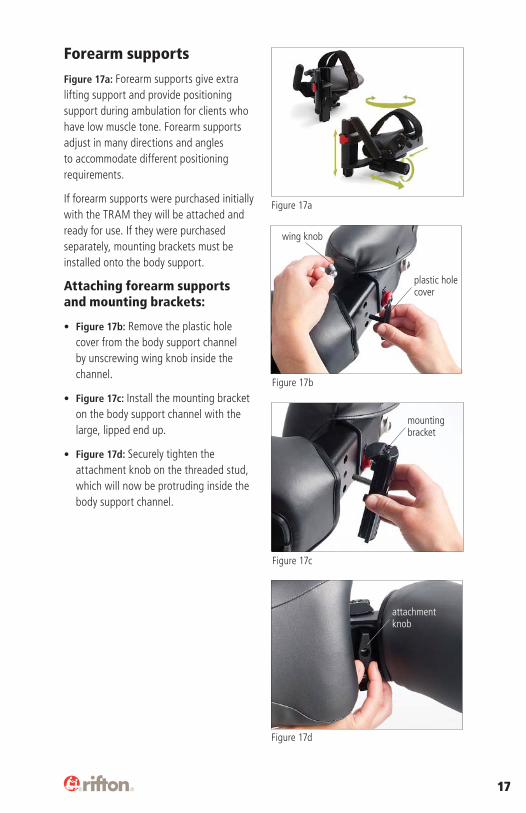
Forearm supports
Figure 17a: Forearm supports give extra lifting support and provide positioning support during ambulation for clients who have low muscle tone. Forearm supports adjust in many directions and angles to accommodate different positioning requirements.
If forearm supports were purchased initially with the TRAM they will be attached and ready for use. If they were purchased separately, mounting brackets must be installed onto the body support.
Attaching forearm supports and mounting brackets:
• Figure 17b: Remove the plastic hole cover from the body support channel by unscrewing wing knob inside the channel.
• Figure 17c: Install the mounting bracket on the body support channel with the large, lipped end up.
• Figure 17d: Securely tighten the attachment knob on the threaded stud, which will now be protruding inside the body support channel.
plastic hole cover
Figure 17d
mounting bracket
attachment knob

18
Adjustments
Figure 18a:
Height adjustment
Press button (A) and slide the post to the desired height.
Loosen knob (B) to:
• Slide the arm pad toward or away from the user.
• Rotate up or down.
• Rotate in or out.
• Move the arm pad backward or forward.
To adjust the handgrip:
1. Loosen knob (C).
2. Slide the handgrip (F) forward or back to match the client’s forearm length.
3. Rotate the handgrip from side to side.
Arm strap (D) and wrist strap (E) are used to secure the client’s arm in the forearm support.
To remove the mounting brackets:
1. Figure 18b: Unscrew the attachment knob located inside the body support channel.
2. Figure 18c: Remove the forearm support mounting bracket.
3. Figure 18d: Install the oval shaped hole cover (found in accessory carton) by inserting the threaded stud through center hole and tightening the wing knob inside the body support channel onto the stud.
Figure 18a
AA
CCEEBB
DD
Figure 18b
Figure 18c
Figure 18d
FF
attachment knob

19
Arm platforms
Attaching/detaching see pp 17 – 18.
Adjustments
Height adjustment:
Figure 19a: Press button (A) and slide the post to the desired height.
Figure 19b:
Loosen knob (B) to:
1. Tilt for forward or backward slant.2. Rotate horizontally. 3. Slide the arm platform toward or away
from the client along the post.
To move the arm platform between backward and forward positions:
• Loosen knob (B). • Remove the arm platform pad from
the post.• Spin the ratchet mechanism 180˚ so that
the sleeve is in the opposite position.• Remount the arm platform pad to
the post.
Figure 19c: The arm straps (C) and wrist strap (D) secure the client’s arm in the arm platform. They can be removed completely, if desired; unfasten the strap and pull it out of the slot beneath the platform.
To adjust the optional handgrip:
1. Loosen knob (E).
2. Slide handgrip forward or back for different forearm lengths, or rotate the it from side to side. The arm straps (C) and wrist strap (D) secure the client’s arm in the arm platform.
Figure 19a
Figure 19b
33
11
22
BB
AA
Figure 19c
CC
EEDD
20
Operation To avoid injury, do the following before and during every transfer:
• Move the origin and the destination of the transfer as close to each other as possible.
• Ensure that the body support system is positioned comfortably, correctly and securely, and that the safety buckle is properly engaged.
• Lift the client only high enough to perform the transfer.
• Check that the straps are snug and the body support system does not slide up or cause discomfort.
Aside from weighing and off-weighting (see page 13), the TRAM offers three essential functions: seated transfers (ideal for toileting), sit-to-stand lift and gait training. The following two pages illustrate these functions.
WARNING
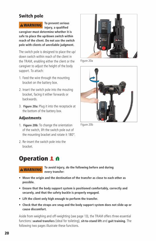
Switch poleTo prevent serious injury, a qualifi ed
caregiver must determine whether it is safe to place the up/down switch within reach of the client. Do not use the switch pole with clients of unreliable judgment.
The switch pole is designed to place the up/down switch within reach of the client in the TRAM, enabling either the client or the caregiver to adjust the height of the body support. To attach:
1. Feed the wire through the mounting bracket on the battery box.
2. Insert the switch pole into the mouting bracket, facing it either forwards or backwards.
3. Figure 20a: Plug it into the receptacle at the bottom of the battery box.
Adjustments
1. Figure 20b: To change the orientation of the switch, lift the switch pole out of the mounting bracket and rotate it 180°.
2. Re-insert the switch pole into the bracket.
WARNING
Figure 20a
Figure 20b

21
Using thigh straps for a seated transfer:
1. Clip one end of each thigh strap onto the yellow clips at the front of the TRAM's body support system.
2. Figure 21a: With the client sitting up, arms raised slightly, position the body support system pads around the client’s rib cage a few inches below the armpits.
3. Figure 21b: Secure snugly with the buckle and adjustment strap.
4. Figure 21c: Attach the thigh straps (gray side up) to one of the colored clips along each side of the body support system. For clients with lower tone, choose a clip further back for greater support. Pull the straps snugly, making sure both thigh pads are positioned under the client’s thigh and adjusted equally.
5. Figure 21d: Raise the client. Watch closely to make sure the client remains comfortable and does not sag. Move the client to the transfer location. The TRAM base legs should be retracted for travel.
6. Figure 21e: Gently lower the client onto the seat. Avoid lowering too far so the body support system doesn’t push down on the client’s hips. (The TRAM will automatically stop and beep if it meets resistance.) Unclip the back ring on the thigh straps and pull the straps out from under the client. Then release the back buckle.
Figure 21a
Figure 21b
Figure 21c
Figure 21d
Figure 21e
22
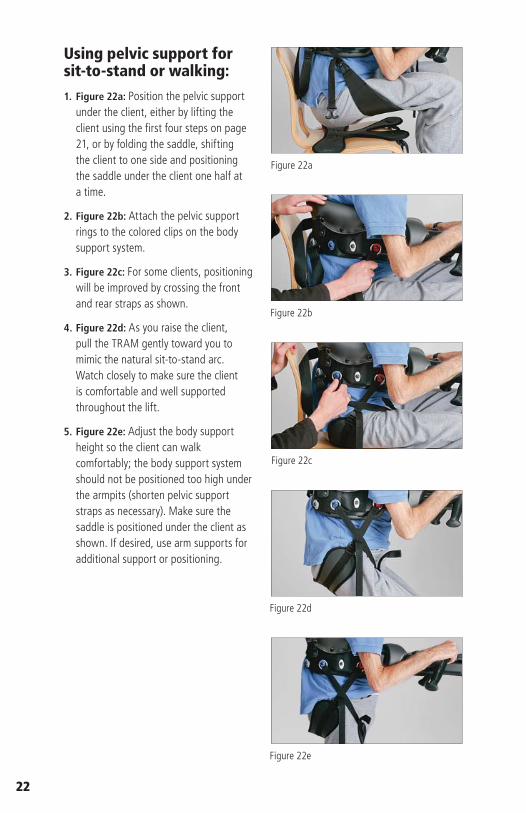
Using pelvic support for sit-to-stand or walking:
1. Figure 22a: Position the pelvic support under the client, either by lifting the client using the fi rst four steps on page 21, or by folding the saddle, shifting the client to one side and positioning the saddle under the client one half at a time.
2. Figure 22b: Attach the pelvic support rings to the colored clips on the body support system.
3. Figure 22c: For some clients, positioning will be improved by crossing the front and rear straps as shown.
4. Figure 22d: As you raise the client, pull the TRAM gently toward you to mimic the natural sit-to-stand arc. Watch closely to make sure the client is comfortable and well supported throughout the lift.
5. Figure 22e: Adjust the body support height so the client can walk comfortably; the body support system should not be positioned too high under the armpits (shorten pelvic support straps as necessary). Make sure the saddle is positioned under the client as shown. If desired, use arm supports for additional support or positioning.
Figure 22a
Figure 22b
Figure 22c
Figure 22d
Figure 22e

23
Old batteries should be disposed of properly at an appropriate recycling facility.
Battery chargerTo prevent shock or electrocution, do not
charge batteries in a wet area.
Installation 1. Remove the battery from the charger to
access the mounting bracket.
2. Figure 23a: Attach the charger to the wall near an outlet, using two screws (A). Two screws are provided with the charger, however, they may not be suitable for every situation.
3. Figure 23b: Place the battery in the charger.
4. Plug the charger cord into a wall outlet.
Charging • Charge the battery for 24 hours before
fi rst use.
• Recharge the battery each night even if the battery box light is still green.
• To charge the battery, remove it from the battery box and place it onto the wall-mounted charger.
• The charger and indicator light will shut off automatically when charging is complete.
• Charging normally takes approximately six hours.
• During long periods of inactivity or storage, batteries will lose charge. Allowing batteries to deep cycle (become nearly or completely dead) will destroy them. To prevent this, store batteries in the charger. If you purchased an extra battery, consider purchasing a second charger.
Figure 23a
Figure 23b
AA
WARNING

24
Scale display is blank.
Make sure four new AA batteries are inserted correctly.
TRAM veers to the side.
If the fl oor is uneven and TRAM veers to one side, we recommend the use of one or more swivel locks.
Lift only goes up or only goes down. Green light on battery box is on.
This problem might be caused by a faulty switch on the caregiver handle/switch pole. If the up and down switches on the battery box work, then replace the caregiver handle or switch pole.
Lift does not go up or down when battery is inserted and green light on battery box is on.
The problem could be either a faulty switch or lift actuator. First ensure that the wires at the bottom of the battery box are plugged in properly. Then check to see if the up and down switches on the battery box work. If they work, replace the caregiver handle or switch pole. If the battery box up and down switches don’t work, replace the actuator.
Lift does nothing when battery is inserted. Green light on battery box does not go on.
The problem may be a faulty or dead battery or a failed battery box. First make sure battery is latched securely into battery box (see page 9). Then charge the battery or fi nd an alternative battery. If the battery is more than three years old, consider replacing it. If the TRAM still does not function, replace the battery box.
Lift does not go up or down. Light on battery box is red.
This indicates a critically low battery level. Recharge the battery. When the light is red, the TRAM can still be lowered using the emergency lowering button on the battery box.
Lift goes up or down without pressing the switch. (The red E-Stop button will always stop all movement.)
Unplug the front handle or switch pole cord. The cord is on the left and has a plug similar to a phone cord or network cable. If this stops the motion, the caregiver handle or switch pole should be replaced. If not, the battery box is faulty.
Light on battery box is green when battery is inserted but goes off when the up button is pressed. Battery doesn’t seem to hold a charge.
When the battery is at the end of its useful life, the voltage may drop so rapidly that the indicator will no longer show orange or even red. Its performance will diminish, and it may no longer hold a charge. Replace the battery.
The TRAM battery has a maximum life of fi ve years. This life span is shortened if the battery discharges too deeply. Charge your battery as often as possible and store it on the charger when not in use.
Lift beeps when down button is pushed.
For safety, the TRAM’s actuator control system continuously monitors the force exerted by the actuator as the body support is lowered. It stops if an excessive rise in force is detected, for example the body support pushing down on the client’s hips. The battery box will beep if this happens, and will continue beeping until the down button is released.
This system is sensitive and may occasionally issue a false alert, especially if the TRAM is cold or has been idle for some time. If a false alert occurs, re-engage the down button.
Troubleshooting

25
Technical data
• Lifting speed: 1.5" (4 cm) / sec with no load.
• Battery: 24V, 2.9 Ah valve-regulated lead-acid gel-type batteries. (Replacement batteries available from Rifton)
• Battery charger: Wall-mounted charger, 100 - 240 V AC, max 650 mA.
• Motor: 24 V, 6A, permanent magnet motor.
27½"(70 cm)
21½"(55 cm)
46"(117 cm)
• Emergency lowering: Electrical
• Wheels: K310: 4" (100mm) dualK320: 3" (75 mm) dual (front wheels have brakes)
• Motor duty cycle: Two minutes continuous use followed by 18 minutes idle.
• Turning diameter: 50" (127 cm)
• Mass of TRAM: 70 lbs (32 kg)
43½"(110 cm)
45½"(116 cm)
31½"(80 cm)
58"(147 cm)
7"(18 cm)

26
CAUTION
Maintenance This product is designed and tested for an expected life of 5 years when used and maintained in accordance with this manual. At all times, users must ensure that the product remains in a safe and useable condition, including regular maintenance and inspections as specifi ed in the manual.
To prevent structural failure, which may result in serious injury or death:
• Inspect this product and accessories regularly for loose or missing screws, metal fatigue, cracks, broken welds, missing attachments, general instability or other signs of excessive wear.
• Immediately remove this product from use when any condition develops that might make operation unsafe.
• Do not use Rifton components or products for any purpose other than their intended use.
• Replace or repair components or products that are damaged or appear to be unstable.
• Use only Rifton authorized replacement parts. Order information for replacement parts is provided on the back of this product manual.
Cleaning To minimize risk of infectious disease transmission, clean and disinfect the TRAM between uses by different patients.
To avoid damaging the product:
• Do not use excessive amounts of water when cleaning the TRAM.
• Do not use high-pressure spray or steam cleaning.
• Do not clean the piston rod of the TRAM’s electric actuator.
The TRAM and its accessories may be cleaned with broad spectrum, multi-purpose disinfectant sprays and wipes or a solution of up to 10% bleach. Do not use solutions containing perfumes or staining ingredients. The leg straps, pelvic support and removable back belt (if installed) may be machine washed in cold water and air dried.
NOTICE

27
WARNING
Warranty Statement If a Rifton product breaks or fails in service during the fi rst year, we will replace it free of charge.
Materials • Steel hardware items (nuts, bolts, screws, etc.) are typically zinc or nickel plated, or
stainless steel.
• Upholstery items (pads, support blocks, padded prompts, etc) are typically polyurethane foam with a fi re-retardant cover made from expanded polyurethane and tough nylon.
• Frames are typically steel or aluminum tubing, welded together and are fi nished with powder coated paint. Some frame components may also be stainless steel.
• Straps are typically made of polypropylene or nylon webbing.
• Plastic components are typically injection molded from a variety of industrial resins.
All components are lead free and not made with natural rubber latex.
User modifi cations To prevent serious injury or death, do not modify or alter Rifton products or components, or use Rifton products or components
in conjunction with products from other manufacturers. Rifton does not accept responsibility for any modifi cations or alterations made to our components or products after they leave our premises. Customers modifying or altering our components or products, or using them in conjunction with products from other manufacturers, do so at their own risk.
28
Rifton Contact Information
MailRifton EquipmentPO Box 260Rifton NY 12471–0260
Fax800.865.4674
Phone800.571.81989–5 EST
Onlinewww.Rifton.com
To order replacement parts1. Locate the ID number of the product on the small white label.
2. Have this number available when you call 800.571.8198 for your customer service representative.
Use only replacement parts supplied by Rifton Equipment.
We are glad to supply replacement parts. Although Rifton makes every effort to supply correct parts and instructions for repairing or refurbishing your equipment, you are responsible to make sure that the repairs or modifi cations are correctly and safely completed.
HL99 ECO
3632 Revision 06
Find letters of medical necessity and informative articles at:www.rifton.com/tram