revisit of synchronized electric charge extraction (sece
TRANSCRIPT

Revisit of synchronized electric chargeextraction (SECE) in piezoelectric energyharvesting by using impedance modeling
Chen Chen, Bao Zhao and Junrui Liang
School of Information Science and Technology, ShanghaiTech University, Shanghai, People’s Republic ofChina
E-mail: [email protected]
Received 26 January 2018, revised 27 June 2019Accepted for publication 6 August 2019Published 23 September 2019
AbstractPiezoelectric energy harvesting (PEH) systems convert ambient vibration energy into usefulelectricity. An interface circuit intervenes the electromechanical energy conversion; it has asignificant effect on the electromechanical joint dynamics and harvested power. Among theexisting interface circuits, the synchronized electric charge extraction (SECE) solution wasknown for its unique feature of load independence. However, the actual harvested power wasusually shown to be lower than the previous theoretical predictions. The reason is that the energydissipation in power conditioning, e.g. the diode dissipation in the rectifier and the switchingdissipation in each energy extraction, have not received sufficient consideration. This paperrevisits the joint dynamics and harvested power of PEH systems with a SECE interface circuit byusing the energy flow analysis and impedance modeling. By qualitatively scrutinizing the energycycle of SECE, the electrically induced dynamic characteristics are broken down into threecomponents: the equivalent capacitance, dissipative resistance, and harvesting resistance, whichhave the same effects but different values, like those in other PEH interface circuits. The threecomponents are equivalent to an additional stiffness, a dissipative damper, and a regenerativedamper in the mechanical domain. The theoretical harvested power, which is estimated based onthe impedance modeling, shows good agreement with the experimental results under differentloading conditions and operating frequencies. Owing to its modular way of thinking, theimpedance modeling technique once again shows its effectiveness and efficiency towards theanalyses of joint dynamics and harvested power in PEH systems using different powerconditioning interface circuits.
Keywords: Piezoelectric energy harvesting, synchronized charge extraction, electromechanicaljoint dynamics, impedance modeling, energy flow
(Some figures may appear in colour only in the online journal)
1. Introduction
Kinetic energy harvesting is one of the most extensivelyinvestigated energy harvesting technologies towards the rea-lization of the energy-self-sufficient distributed Internet ofThings (IoT) devices. The piezoelectric materials, as one ofthe favorite electromechanical transducers, can be used toconstruct compact (in mechanical structure) and efficient (inenergy conversion) energy harvesting systems [1, 2]. Given
these two outstanding features, during the last decade, muchresearch effort has been made by mechanical engineers,electrical engineers, and material scientists towards betterunderstanding and improvement of piezoelectric energy har-vesting (PEH) systems.
The piezoelectric transducers generate AC (alternativecurrent) voltage under vibration, while digital electronics as theload devices require a stable DC (direct current) voltage torun. A power conditioning circuit is necessary for fulfilling the
Smart Materials and Structures
Smart Mater. Struct. 28 (2019) 105053 (12pp) https://doi.org/10.1088/1361-665X/ab38fb
0964-1726/19/105053+12$33.00 © 2019 IOP Publishing Ltd Printed in the UK1

AC-to-DC power conversion. The studies of power con-ditioning interface circuits for PEH systems started from 2002,in which a simple full-wave bridge rectifier was used for theAC-to-DC conversion [3, 4]. Given its passive operation andeasy-to-implement feature, the full-wave bridge rectifier isextensively used hereafter and referred to as the standardenergy harvesting (SEH) interface circuit for PEH [5]. Laterstudies have shown that, besides only making the AC-to-DCconversion, the interface circuits have a significant effect on thePEH enhancement [2]. In particular, the PEH capability can beincreased by several folds by using a family of power elec-tronic circuits, which are called the synchronized switch har-vesting on inductor (SSHI) [6, 7], or the bias-flip rectifier in theintegrated circuit (IC) research community [8]. However, theharvested power by the aforementioned interface circuits variesunder different loading conditions; a second stage maximumpower point tracking (MPPT) module is necessary for main-taining the optimal harvested power for those solutions. Dif-ferent from the SSHI solutions, the synchronous electriccharge extraction (SECE) and its derivatives can also enhancethe harvested power, which is independent of the load [9].The load-independent feature of SECE is unique and alwayshighlighted in the comparisons of different interface circuits[2, 6, 10]; even its maximum harvesting capability is not assignificant as other synchronized switch counterparts. Whenthe harvested power is independent of the loading condition,the second stage MPPT module is no longer necessary fortuning the equivalent load towards better harvesting perfor-mance. Therefore, the SECE solution is more compact andstable for practical PEH implementations.
The load-independence of SECE has attracted muchresearch interest. It was proven that, under the weakly cou-pled condition, the harvested power obtained with SECE isapproximately four times of that with SEH [10]. Wu et alhave developed a self-powered interface circuit called opti-mized SECE (OSECE) [11] for further increasing the har-vested power beyond the four-time limitation under weakcoupling. Lallart et al have introduced a heterogeneousswitching strategy by combining and coordinating the SSHIand SECE actions in different cycles and successfully gotmore harvested power under weak coupling. Considering theunder-performance of SECE beyond mid-range electro-mechanical coupling, Richter et al [12] and Xia et al [13]have proposed the partial charge extraction solution forimproving the harvesting capability of SECE under moder-ately and strongly coupled conditions. Morel et al have rea-lized another solution by heterogeneously skipping the switchactions in N cycles [14]. Such a solution was called N-SECE.The harvesting bandwidth problems with SECE have alsobeen discussed and improved by introducing a phase lead/lagto the synchronized switch instants [15, 16]. Besides the newsolutions towards better harvesting performance under dif-ferent coupling levels and frequency bands, many otherpapers have discussed the implementation issues of SECE,e.g. the integrated circuit (IC) solutions of SECE [17, 18].
The interface circuits play an essential role in PEHenhancement under resonant conditions, in particular for weaklycoupled systems [19, 20]. On the other hand, when putting the
interface circuits into the practical electromechanically coupledscenario, the effect of the electrical manipulations, such as theelectrically induced damping, can be quantified by studying theelectromechanical joint dynamics of the PEH systems. Fol-lowing the analytical formula proposed by Shu et al in theiranalyses of SEH and SSHI [19, 20], Tang and Yang [10] havestudied the joint dynamics and harvested power of SECE underdifferent coupling conditions. As most of the studies aboutstructural dynamics, the methodology used by Shu et al startsfrom the equations of motion, the closed-form expressionssummarizing the constitutive behavior of an entire system. Inpiezoelectric systems, such equations of motion are synthesizedby the actuating equation, sensing equation, and constitutiverelation of the nonlinear power conditioning circuit. The top-down solutions emphasize the system-level expression of thejoint dynamics. The flattened and inclusive equation of motionmight not be reusable when the interface circuit is changed. Forexample, to analyze the dynamics of PEH systems using SEH[19], parallel SSHI (P-SSHI) [20], series SSHI (S-SSHI) [21],or SECE [10], all derivations were redone from the beginningbased on the energy-balance formula. Moreover, when a systemgets more complicated, e.g. when the effect of dielectric lossmust be included in the model [22], the top-down method canhardly lead to an explicit closed-form solution.
Like what a computer programmer encounters when writ-ing a big and comprehensive computer program, the monolithicway of thinking makes it difficult to fulfill complicated orcollaborative tasks. Therefore, a big program is often imple-mented by taking the modular way of thinking. By breakingdown a big task into several independent modules, the final goalcan be realized with better-defined procedures or sub-functions.Liang and Liao have proposed such a bottom-up modularsolution for PEH systems in their impedance modeling andanalysis for SEH, P-, and S-SSHI interface circuits [23]. In theirstudy, by clarifying the energy flow within the PEH systems[5, 24], the dynamic behaviors of different interface circuitswere decomposed into three general components, i.e. the har-vesting resistance, dissipative resistance, and equivalent capa-citance. The relations among those three equivalent componentscan be intuitively shown in the partitioned work cyclescorresponding to different interface circuits. The use of differentinterface circuits does not change the system-level expressionsbut just differs in the values of the three equivalent components.Therefore, the system-level expressions can be reused; theimpedance model can be easily transplanted to other PEHinterface circuits with more comprehensive details [22] andeven other kinetic energy harvesting systems [25].
In the study of a PEH system using the SECE interfacecircuit, Lefeuvre et al have drawn the picture of the work cyclein their initial investigation [9]. The dynamic details have notbeen specified towards the general impedance expressions.Moreover, since the ideal lossless rectifier and lossless switchaction were assumed in the previous studies, the observedexperimental results are always lower than the simple theor-etical prediction [9, 10]. Considering the aforementionedinsufficiencies, this paper revisits the joint dynamics of the PEHsystems using SECE and provides a more accurate theoreticalprediction of the harvested power. A better insight towards the
2
Smart Mater. Struct. 28 (2019) 105053 C Chen et al

joint dynamics can be obtained by using the bottom-up impe-dance modeling with a modular way of thinking.
2. System configuration
A typical PEH system is composed of three parts: thedeforming mechanical substrate, piezoelectric transducer, andpower conditioning circuit, as shown in figure 1. The interfacecircuit is at the front end of a power conditioning circuitconverting the AC power from the piezoelectric transducerinto a stable DC energy, which is stored in the energy storage.Given the bi-directional coupling effect of a piezoelectrictransducer, the AC end of the interface circuit also introducesa backward dynamic effect to the vibrating structure. There-fore, the interface circuit plays a crucial role in PEHenhancement at resonance, and it also provides a possible wayfor broadening the bandwidth of the system [26, 27].
Given the constitutive relations in the piezoelectric elements[28], the electrical part of a PEH transducer can be regarded as acurrent source ieq, whose value is proportional to the vibrationvelocity x, connecting in parallel with the piezoelectric clampedcapacitance Cp and the dielectric leakage resistance Rp. Thepiezoelectric equivalent is shown in figure 2(a). Rp usually has alarge value and is regarded as ignorable when the circuit doesnot operate under a high-power condition [22], e.g. with theSEH circuit or SECE in this paper; therefore, for the two cur-rents shown in the piezoelectric equivalent, we have »i ih eq.When no power conditioning circuit is connected, i.e. the open-circuit condition, the voltage across the piezoelectric transducervp is just proportional to the integral of ih. The magnitude ofnominal open-circuit voltage
( )w w
= »VI
C
I
C, 1oc
h
p
eq
p
where Ih and Ieq are the magnitudes of ih and ieq, respectively.ω is the angular frequency of the vibration.
The SECE circuit operates at the open-circuit condition inmost of a vibration cycle, except the zero-crossing instants of theequivalent current ieq, which are called the synchronized instants.At every synchronized instant, the initial condition of the ieqintegral is reset to zero by removing (extracting) all the chargestored in Cp. The circuit operation and characteristic waveformsof the SECE interface circuit in a vibration cycle are shown in
figure 2. The SECE circuit consists of a full-wave bridge rectifierand a buck-boost converter, which operates in a highly dis-continuous conduction mode (DCM). But different from theconventional pulse width modulation (PWM) controlled buck-boost converter, the switching cycle of SECE strictly follows themechanical vibrations at the synchronized instants, i.e. the zero-crossing points of velocity or, equivalently, the extremes ofdisplacement.
In the positive-current half cycle, when ieq>0, the SECEaction can be divided into three phases: the open-circuit,switching, and freewheeling (charging) phases, as illustratedin figures 2(a)–(i).
Open-circuit phase. Figure 2(a) illustrates the conductingpaths during the open-circuit phase in red. The duration ofthis phase is approximately half of a vibration cycle. Theswitch S and diode D are at the off state; therefore, the SECEcircuit takes no action during this phase. vp is the integral ofieq starting from a zero initial voltage, as highlighted by thered segment in figure 2(d) and (e).
Switching (extraction) phase. When the displacement of thepiezoelectric beam reaches its maximum values, the switch S isturned on for slightly more than one fourth of an L Ci p cycle, inorder to activate the switching phase. The conducting paths inthe switch phase are highlighted in red in figure 2(b). In thisphase, Cp and Li form an LC circuit, through which the energystored in Cp is rapidly transferred to Li. As vp the voltage acrossthe piezoelectric element is proportional to the charge stored inCp, vp drops immediately to zero after one fourth of the L Ci p
cycle, as highlighted in red in figure 2(f) and (g). Strictlyspeaking, vp drops to twice of the diode forward voltage afterone fourth of the L Ci p cycle. The turn-on interval of S isdesigned slightly longer then one fourth of the cycle to ensurethe full discharge of Cp. The charge extraction will be auto-matically stopped by the rectifier when vp reaches zero. Afterthis switch-on period, most of the energy stored in Cp is trans-ferred into Li, while the rest is dissipated at r the equivalentseries resistance (ESR) of the switching branch.
Freewheeling (charging) phase. After the switch phase,the switch S is turned off, the energy accumulated in Li istransferred into the filter capacitor Cr through the free-wheeling diode D. Cr is designed to be much larger comparedto Cp for providing a DC output voltage for the load resist-ance Rl. The conducting paths in this phase are highlighted inred in figure 2(c). As the conducting paths are not connectedto the piezoelectric source, they do not influence the piezo-electric element. In other words, the source and load aredecoupled by the intermediate inductance Li. Such a decou-pling feature is quite similar to the buck-boost DC-to-DCconverter in power electronics, except that SECE here con-verses AC power into DC. Since the piezoelectric element isnot involved in the freewheeling phase, this phase has noeffect on the piezoelectric voltage vp. The correspondingwaveforms are shown in figure 2(h) and (i). The freewheelingdiode D stops conduction until the current iLi drops to zero, asshown in figure 2(i).
In the other half of a vibration cycle, i.e., the negative-current one when ieq<0, the operation can be also divided intothree phases, which are reciprocal to those threes in the
Figure 1. A typical cantilevered PEH system.
3
Smart Mater. Struct. 28 (2019) 105053 C Chen et al

positive-current half cycle. The corresponding conductingcircuit branches and waveforms are shown in figure 2(j)–(r).
From the profile of piezoelectric voltage vp, as shown infigure 2, we can find that it has the same sign as the currentsource ieq throughout a vibration cycle; therefore, the powerextracted from the mechanical source is always positive.Given the decoupling between the source and load, the vpwaveform does not change under different loading conditions,which enables the load-independent feature of SECE.
The analyses of SECE in the previous literature werebased on the assumption of ideal lossless energy transfersfrom Cp to Li and then from Li to Cr. Nevertheless, energydissipation, in fact, exists in the power conditioning process.The energy dissipation is basically caused by:
• the practical bridge rectifier, whose forward voltage dropVF is nonzero;
• the practical series L Ci p circuit, whose quality factor Q isfinite;
• the practical freewheeling diode D, whose forwardvoltage drop VD is nonzero.
Such an energy dissipation mechanism might discount thetotal extracted energy and also affect the joint dynamics of theelectromechanical system. The energy flow and equivalentdynamic details are also of necessity towards the compre-hensive understanding of SECE.
3. Impedance of the Cp and SECE combination
For evaluating the joint dynamics of an entire PEH system, wehave to first formulate both the mechanical and electrical parts ina mathematical uniform. Considering the parameter-distributedfeature of a piezoelectric cantilever and the nonlinear feature of aPEH power conditioning circuit, the most compatible way is tomodel or approximately express the dynamics of both parts interms of equivalent impedance [22, 23].
In the equivalent impedance model, the mechanical partcan be simply modeled as a single-degree-of-freedom (SDOF)lumped mass-spring-damper vibrator, whose vibration velo-city x is proportional to the equivalent current ieq in theelectrical part, as shown in figure 2, i.e.
( ) ˙( ) ( )a=i t x t , 2eq e
where αe is the voltage-to-force or velocity-to-current cou-pling factor. Considering the actual mechanical dynamics, thecurrent source ieq in figure 2(a) represents the composition ofa series resistor-inductor-capacitor (RLC) resonant circuitdriven by an equivalent voltage veq, as shown in figure 3. Theequivalent voltage is proportional to the force applied to thevibrator with the relation as follows
( ) ( ) ( )a
=v tf t
. 3eqe
Figure 2. The circuit topology (a)–(c) & (j)–(l) and characteristic waveforms (d)–(i) & (m)–(r) in the six phases of a vibration cycle. Theconducting circuit paths and the corresponding waveform portions are shown in red. (a), (d), & (e) Open-circuit phase in the positive-currenthalf cycle. (b), (f), & (g) Switching phase at displacement maximum. (c), (h), & (i) Freewheeling charging phase at displacement maximum.(j), (m), & (n) Open-circuit phase in the negative-current half cycle. (k), (o), & (p) Switching phase at displacement minimum. (l), (q), & (r)Freewheeling charging phase at displacement minimum.
4
Smart Mater. Struct. 28 (2019) 105053 C Chen et al

The equivalent resistor R, inductor L, and capacitor C in theresonant circuit represent the damping D, mass M, and stiff-ness K in the mechanical domain with the relations as follows[23]
( )a a
a= = =R
DL
MC
K, , . 4
e e
e2 2
2
The SDOF electromechanical analogy of the mechanicalvibrator was well established. The key problem to formulatethe uniform model is how to express the equivalent impe-dance of the harvesting interface circuits. It was discussed in[22, 23] that the exact expression of the harvesting interfacecircuit cannot be obtained separately without considering thesource impedance, in particular, the piezoelectric clampedcapacitance Cp. Therefore, for the SECE circuit, we need toconsider Cp and the SECE circuit as a whole for quantifyingthe equivalent impedance.
Taking the equivalent impedance of the Cp and SECEcombination as ZC SECEp
, we assume that the current flowingthrough ZC SECEp
as a sinusoidal current, i.e.
( ) ( ) ( ) ( )w w= »i t I t I tsin sin . 5h h eq
The approximation holds for large [ ] R ZRep C SECEp,
which might be violated when a power-boosting interfacecircuit, such as SSHI, is adopted [22]. In the experimentalPEH structure used in this study, the ratio of Rp over
[ ]ZRe C SECEpis about 5.6, as shown in figure 4, which
satisfies the approximation in (5).The SECE circuit operates at the open-circuit condition
most of the time in a cycle, except the synchronized instantswhen ih crosses zero. At the synchronized instants, the SECEcircuit resets the initial value of vp, which is proportional tothe integral of ih, to zero. Given the waveforms shown infigure 2, vp(t) can be expressed with a piecewise equation, i.e.
( )
( ) ( ) ( )( ) ( ) ( )
⎧⎨⎩w p w pw p w p
= ´- + < +- - + < +
6
v t Vt k t kt k t k
cos 1, 2 2 1 ,cos 1, 2 1 2 1 .p oc
Given the vp expression in (6) and its waveforms shown infigures 2(d) and (f), the expression of the fundamental
harmonic of vp(t) can be obtained as follows
( ) ( ) ( ) ( )⎡⎣⎢
⎤⎦⎥p
w w= -v t V t t4
sin cos . 7p f oc,
The waveform of vp f, is illustrated in figures 2(d)–(i) and(m)–(r) by the dashed lines. The dynamics of ZC SECEp
can beobtained as the ratio of the fundamental harmonic voltage vp f,
over the harmonic current ih in the frequency domain, i.e.
( )( )
( )( )⎜ ⎟⎛
⎝⎞⎠ w
ww w p
= = -Z jV j
I j Cj
1 4. 8C
p f
h pSECE
,p
For the three interface circuits discussed in [23], i.e. SEH,P-SSHI, and S-SSHI, the impedances of the Cp and circuitcombinations are tunable along the corresponding curves inthe complex impedance plane, as shown in figure 4. TheSECE is different from the aforementioned interface circuitsin that it had a fixed impedance, as formulated in (8) andshown in figure 4 with the triangular marker. Moreover, theimaginary part of ZC SECEp
is equal to that in the open-circuitcondition, i.e. −j/(ωCp); its real part is 4/π times of themagnitude of the imaginary part. Unlike those circuits whoseequivalent impedance is on specific one-dimensional trajec-tories. The zero-dimensional impedance point of SECEspeaks its fixed dynamics and load independence in a PEHsystem. Also, under the weakly coupled condition, only thereal part of ZC Cirp
decides the maximum extracted power ofdifferent interface circuits. As we can observe from figure 4,the SECE has enlarged the real part of the impedance, com-pared to SEH; yet, its real part cannot catch up with the SSHIinterface circuits. Since the maximum real part of SEH is1/(πωCp) [23], the real part of SECE is just four times of thisnumber in SEH. This four-time extracted power under theweakly coupled condition was proven in the previous litera-ture [9, 10]. We here offer another explanation on this four-time relation from the equivalent impedance point of view.
With the harmonic approximation on the dynamics of theCp and SECE combination, the constitutive equation of theentire PEH system can be formulated with the basic circuitlaws as follows
( )( )
( )( )
ww w
wp
p pw= + + +
-
- +
V j
I jR
j Cj L
j R
j C R
1 4
4. 9
eq
eq
p
p p
It is a deterministic dynamic, which is not electrically tunableand only decided by the passive component values of the
Figure 3. Equivalent impedance network of a PEH device using theSECE interface circuit.
Figure 4. The normalized equivalent impedances of the Cp andcircuit combinations ZC Cirp with four PEH interface circuits (SEH,P-SSHI, S-SSHI, and SECE).
5
Smart Mater. Struct. 28 (2019) 105053 C Chen et al

piezoelectric structure. In other words, when the SECEinterface circuit is used for power conditioning, the vibrationof the PEH system does not change under different electricalloading conditions.
4. Detailed impedance breakdowns
With the impedance modeling, we have explained the well-understood result from another point of view. Besides, moreinsights on the dynamic details can be obtained by furtherbreaking down the total impedance ZC SECEp
into threecompositions according to their different functional con-tributions towards the overall dynamics. The energy flowanalysis is essential for revealing both the qualitative andquantitative relations among the three compositions [5, 24].
The general energy flow of an SECE-based PEH systemis shown in figure 5(a). The mechanical energy enters thePEH system from the ambient vibration source and cyclesbetween kinetic and potential energy in the mechanicalresonance tank, as shown by the gray ring. In the resonant
case, there is no energy return from the resonance tank to thesource, while in the off-resonant cases, some of the energyflowing into the reactive component (equivalent mass orstiffness) returns back to the source. During the vibration,some of the mechanical energy is dissipated (converted intothermal energy) due to the mechanical damping, as shown bythe orange branch in figure 5(a). The piezoelectric transducertransfers some mechanical energy into electricity. In SECE,since there is no energy return from the electrical part to themechanical part, the converted energy is just the extractedenergy from the mechanical part. This amount of extractedenergy has two destinations in general. A part of it is con-verted into storable and useful electrical energy, which iscalled the harvested energy. The harvested energy is denotedwith the green arrow in figure 5(a). The rest of the extractedenergy is dissipated, i.e. converted into heat, during the powerconditioning process. Such dissipation is caused by theaforementioned three reasons: the nonzero VF in the bridgerectifier, whose corresponding energy branch is denoted bythe red arrow in figure 5(a); the parasitic resistance in theL Ci p loop, whose corresponding energy branch is denoted by
Figure 5. Detailed energy compositions in SECE. (a) Energy flow chart. (b) The partitioned energy cycle.
6
Smart Mater. Struct. 28 (2019) 105053 C Chen et al

the blue arrow; and the nonzero VD in the freewheeling pathof the converter, whose corresponding energy branch isdenoted by the purple arrow.
With the clarification on the detailed energy flow, we canhave a more comprehensive insight on such a problem thatthe extracted energy is not equal to the harvested energy. Thetotal extraction usually links with the loss factor, whichevaluates the damping effect [5]. However, increasing theextracted energy does not guarantee better harvesting per-formance. The design should be done by taking the harvestedenergy or power as the target for optimization.
The quantitative analysis of extracted energy in SECEcan be carried out by referring to the partitioned energy cycleas shown in figure 5(b). The energy is only extracted from thepiezoelectric capacitance Cp to the harvesting circuit at themaximum or minimum vp instants. Since vp rapidly changesfrom V2 oc or −2Voc to zero, the extracted energy in eachswitching action, which happens in a half vibration cycle, canbe obtained as follows
( )D =E C V2 . 10p oc2
During the switching process, the charge from Cp flowsthrough the bridge rectifier with nonzero VF and the inductivepath with nonzero parasitic resistance r. Both the practicalcomponents produce energy dissipation in each cycle, whichcan be respectively formulated as follows:
( )= D =E QV C V V2 , 11d F p oc F,rectifier
( ) ( ) ( )g= + -E C V V V2 1 , 12d p oc oc F,switch
where γ is called the inversion factor in the SSHI solutions[5]. It is related to the quality factor Q of switching r-Li-Cp
circuit with the following relation
( )( )g = - p-e . 13Q2
The switching dissipation was well-considered in SSHI. Yet,it has not got sufficient consideration in the previous SECEanalysis, which leads to the overestimation on the actualavailable harvested power [9, 10]. For identifying the differ-ent energy portions in the extracted energy, the areascorresponding to Ed,rectifier and Ed,switch are illustrated in redand blue in figure 5(b).
As shown in figure 6, at the end of the switching action,i.e. the t2 instant, vp arrives at zero and Li the current flowingthrough the inductor attains its maximum value1 IL max,i . Theremaining energy, which is transferred into the inductor Li,can be formulated as follows
∣ ∣ ( ) ( )g= -E C V V V2 . 14Li max p oc oc F,
Different from the SSHI solutions, where the inductor is onlyused for voltage inversion, the inductor in SECE serves as anenergy conveyor, which transports the energy from thepiezoelectric source to the separated DC load.
After the t2 instant, the freewheeling phase takes place.The energy stored in Li is released to the storage capacitor Cr
through the freewheeling diode D. The current iLi decreases to
zero with a constant slope of −(VDC+VD). The amounts ofenergy, which are absorbed by D and Cr, are proportional totheir corresponding DC voltages. The energy absorbed byfreewheeling diode D is dissipated into heat, i.e.
( )=+
EV
V VE . 15d
D
DC DLi max,freewheeling ,
The area, which corresponds to Ed,freewheeling, is illustrated inpurple in figure 5. On the other hand, the energy absorbed bythe DC source is the harvested energy, i.e.
( )=+
EV
V VE . 16h
DC
DC DLi max,
The area corresponding to the harvested energy is colored ingreen in figure 5.
The quantitative relations among Ed,rectifier, Ed,switch,Ed,freewheeling, and Eh areas are shown in figure 5(b), given theratios among (11), (12), (15), and (16). The total dissipatedenergy is obtained by combining the three parts of dissipatedenergy in the considered half vibration cycle, i.e.
( )= + +E E E E . 17d d d d,rectifier ,switch ,freewheeling
With the detailed breakdowns of the extracted energy, thereal part of ZC SECEp
can be quantitatively divided into twocomponents, i.e. the harvesting resistance
[ ]
∣ ∣ ˜˜ ˜ ( ˜ ) ( )
pwg
=D
=+
-
RE
EZ
C
V
V VV
Re
41 , 18
hh
C
p
DC
DC DF
SECEp
and the dissipative resistance
[ ]
˜ ˜˜ ˜ ( ˜ ) ( )
⎡⎣⎢
⎛⎝⎜
⎞⎠⎟
⎤⎦⎥
pwg
=D
= + ++
-
RE
EZ
CV
V
V VV
Re
41 1 , 19
dd
C
pF
DC
DC DF
SECEp
where ˜ =V V VDC DC oc, ˜ =V V VF F oc, ˜ =V V VD D oc corre-spond to the normalized DC loading output voltage, nor-malized forward voltage drop of the rectifier, and normalizedforward voltage drop of the freewheeling diode. Rh and Rd
have the same damping effect on the vibrating system, yettheir corresponding amounts of energy have different desti-nations, which should not be mixed up for PEH design andoptimization.
Figure 6. Enlarged view of vp and iLi at a synchronized instantof SECE.
1 The actual current of Li at t2 instant, when vp=0, is slightly smaller thanthe peak current.
7
Smart Mater. Struct. 28 (2019) 105053 C Chen et al

As the values of all dynamic components in theequivalent impedance network shown in figure 3 are obtained,the harvested power can be calculated according to the basiccircuit laws as follows [22]
( )∣ ∣
=+ +
»+
20
PV R R
Z R Z Z Z R
V R
Z Z
2
2,
heq h p
p C C p
eq h
C
2
RLC RLC SECE SECE
2
2
RLC SECE2
p p
p
and the dissipated power is
∣ ∣( )
=+ +
»+
PV R R
Z R Z Z Z R
V R
Z Z
2
2,
21
deq d p
p C C p
eq d
C
2
RLC RLC SECE SECE
2
2
RLC SECE2
p p
p
where
( )⎜ ⎟⎛⎝
⎞⎠w
w= + -Z R j L
C
122RLC
is the total equivalent impedance of the mechanical part. Allparameters in (20) are constants, except that Rh and Rd arefunctions of the normalized DC output voltage VDC. There-fore, strictly speaking, the harvested power also changes withthe output characteristics in practical SECE systems. On theother hand, as we can observe from (18), the dependency isweakened when the voltage of the DC storage is much larger
than the diode voltage drop (usually 0.5 to 0.7 volt). In otherwords, Ph approaches a constant power as VDC gets larger.The harvested power is only a portion of the constantextracted power, rather than all of it. The impedance-basedstudy provides more comprehensive insight on the perfor-mance of the practical SECE interface circuit.
5. Experimental validation
The harvested power analysis for the SECE interface circuit isvalidated by experiments, which are carried out on a base-excited PEH system. The experimental setup is shown infigure 7. The main structure is a piezoelectric cantileveredbeam, which is composed of a PZT patch bonded on a coppercantilever. The cantilever is installed at a vibrating base, whichis excited by a shaker. A pair of magnets is attached at the freeend of the cantilever. The magnets also act as the proof massfor lowering the vibration frequency and increasing thedeformation of the piezoelectric patches. An accelerometer,which is installed at the base, detects the acceleration inthe vibration direction to provide a reference for controlling thevibration exciter. An electromagnetic coil installed near themagnet senses the relative speed of the cantilever beam.The output voltage is sent to the MSP430 micro-controller(EZ430-RF2500, Texas Instrument Inc.) for the synchroniza-tion purpose. Once the MCU catches a zero-crossing point ofthe sensed voltage, which is proportional to the vibrationvelocity, it immediately sends out a switch command to turn onthe electronic switch in the SECE circuit. A multi-functionaloscilloscope (DS1000Z, Rigol Technologies Inc.) is used as the
Figure 7. Experimental setup.
8
Smart Mater. Struct. 28 (2019) 105053 C Chen et al
signal generator and oscilloscope. The magnitude of the baseacceleration maintains at 8.6 m s−2 during the test by referringto the feedback from the accelerometer.
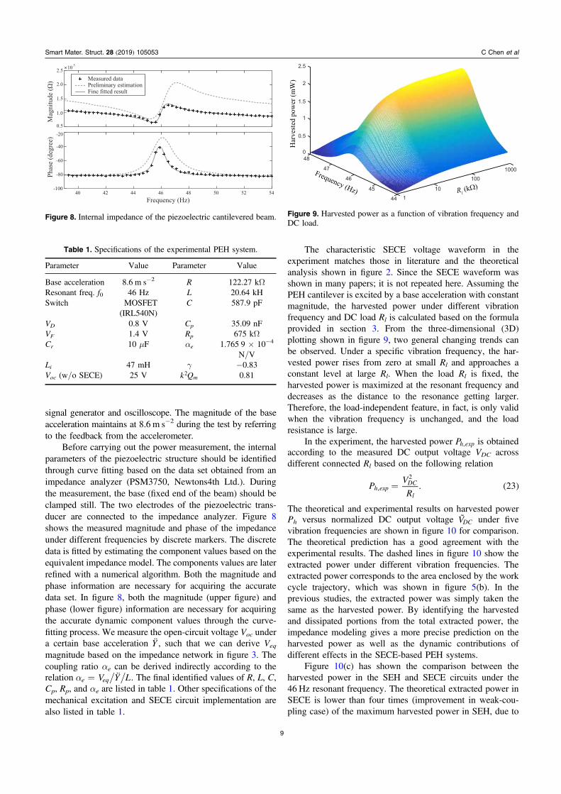
Before carrying out the power measurement, the internalparameters of the piezoelectric structure should be identifiedthrough curve fitting based on the data set obtained from animpedance analyzer (PSM3750, Newtons4th Ltd.). Duringthe measurement, the base (fixed end of the beam) should beclamped still. The two electrodes of the piezoelectric trans-ducer are connected to the impedance analyzer. Figure 8shows the measured magnitude and phase of the impedanceunder different frequencies by discrete markers. The discretedata is fitted by estimating the component values based on theequivalent impedance model. The components values are laterrefined with a numerical algorithm. Both the magnitude andphase information are necessary for acquiring the accuratedata set. In figure 8, both the magnitude (upper figure) andphase (lower figure) information are necessary for acquiringthe accurate dynamic component values through the curve-fitting process. We measure the open-circuit voltage Voc undera certain base acceleration Y , such that we can derive Veq
magnitude based on the impedance network in figure 3. Thecoupling ratio αe can be derived indirectly according to therelation a = V Y L¨e eq . The final identified values of R, L, C,Cp, Rp, and αe are listed in table 1. Other specifications of themechanical excitation and SECE circuit implementation arealso listed in table 1.
The characteristic SECE voltage waveform in theexperiment matches those in literature and the theoreticalanalysis shown in figure 2. Since the SECE waveform wasshown in many papers; it is not repeated here. Assuming thePEH cantilever is excited by a base acceleration with constantmagnitude, the harvested power under different vibrationfrequency and DC load Rl is calculated based on the formulaprovided in section 3. From the three-dimensional (3D)plotting shown in figure 9, two general changing trends canbe observed. Under a specific vibration frequency, the har-vested power rises from zero at small Rl and approaches aconstant level at large Rl. When the load Rl is fixed, theharvested power is maximized at the resonant frequency anddecreases as the distance to the resonance getting larger.Therefore, the load-independent feature, in fact, is only validwhen the vibration frequency is unchanged, and the loadresistance is large.
In the experiment, the harvested power Ph exp, is obtainedaccording to the measured DC output voltage VDC acrossdifferent connected Rl based on the following relation
( )=PV
R. 23h exp
DC
l,
2
The theoretical and experimental results on harvested powerPh versus normalized DC output voltage VDC under fivevibration frequencies are shown in figure 10 for comparison.The theoretical prediction has a good agreement with theexperimental results. The dashed lines in figure 10 show theextracted power under different vibration frequencies. Theextracted power corresponds to the area enclosed by the workcycle trajectory, which was shown in figure 5(b). In theprevious studies, the extracted power was simply taken thesame as the harvested power. By identifying the harvestedand dissipated portions from the total extracted power, theimpedance modeling gives a more precise prediction on theharvested power as well as the dynamic contributions ofdifferent effects in the SECE-based PEH systems.
Figure 10(c) has shown the comparison between theharvested power in the SEH and SECE circuits under the46 Hz resonant frequency. The theoretical extracted power inSECE is lower than four times (improvement in weak-cou-pling case) of the maximum harvested power in SEH, due to
Figure 8. Internal impedance of the piezoelectric cantilevered beam. Figure 9. Harvested power as a function of vibration frequency andDC load.
Table 1. Specifications of the experimental PEH system.
Parameter Value Parameter Value
Base acceleration 8.6 m s−2 R 122.27 kΩResonant freq. f0 46 Hz L 20.64 kHSwitch MOSFET
(IRL540N)C 587.9 pF
VD 0.8 V Cp 35.09 nFVF 1.4 V Rp 675 kΩCr 10 μF αe 1.765 9×10⁻⁴
N/VLi 47 mH γ −0.83Voc (w/o SECE) 25 V k Qm
2 0.81
9
Smart Mater. Struct. 28 (2019) 105053 C Chen et al
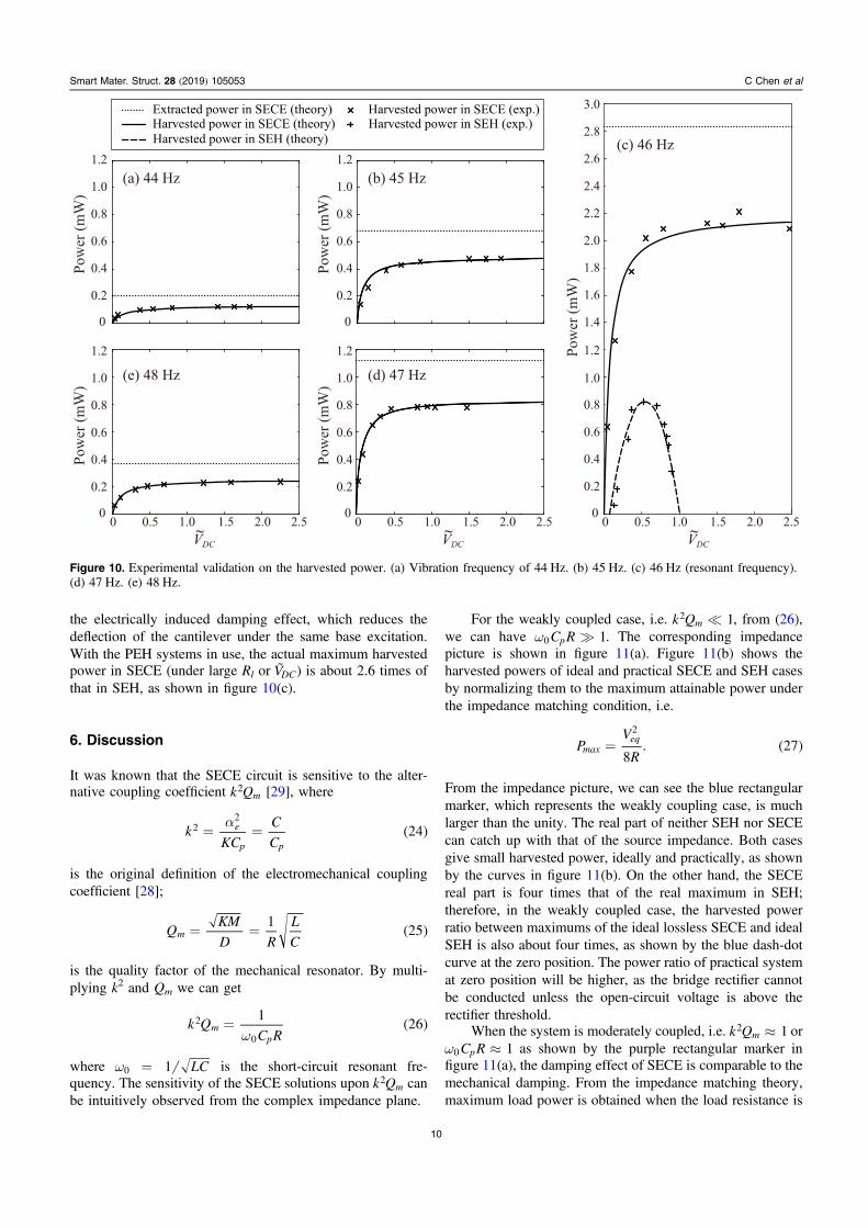
the electrically induced damping effect, which reduces thedeflection of the cantilever under the same base excitation.With the PEH systems in use, the actual maximum harvestedpower in SECE (under large Rl or VDC) is about 2.6 times ofthat in SEH, as shown in figure 10(c).
6. Discussion
It was known that the SECE circuit is sensitive to the alter-native coupling coefficient k Qm
2 [29], where
( )a= =k
KC
C
C24e
p p
22
is the original definition of the electromechanical couplingcoefficient [28];
( )= =QKM
D R
L
C
125m
is the quality factor of the mechanical resonator. By multi-plying k2 and Qm we can get
( )w
=k QC R
126m
p
2
0
where w = LC10 is the short-circuit resonant fre-quency. The sensitivity of the SECE solutions upon k Qm
2 canbe intuitively observed from the complex impedance plane.
For the weakly coupled case, i.e. k Q 1m2 , from (26),
we can have w C R 1p0 . The corresponding impedancepicture is shown in figure 11(a). Figure 11(b) shows theharvested powers of ideal and practical SECE and SEH casesby normalizing them to the maximum attainable power underthe impedance matching condition, i.e.
( )=PV
R8. 27max
eq2
From the impedance picture, we can see the blue rectangularmarker, which represents the weakly coupling case, is muchlarger than the unity. The real part of neither SEH nor SECEcan catch up with that of the source impedance. Both casesgive small harvested power, ideally and practically, as shownby the curves in figure 11(b). On the other hand, the SECEreal part is four times that of the real maximum in SEH;therefore, in the weakly coupled case, the harvested powerratio between maximums of the ideal lossless SECE and idealSEH is also about four times, as shown by the blue dash-dotcurve at the zero position. The power ratio of practical systemat zero position will be higher, as the bridge rectifier cannotbe conducted unless the open-circuit voltage is above therectifier threshold.
When the system is moderately coupled, i.e. »k Q 1m2 or
w »C R 1p0 as shown by the purple rectangular marker infigure 11(a), the damping effect of SECE is comparable to themechanical damping. From the impedance matching theory,maximum load power is obtained when the load resistance is
Figure 10. Experimental validation on the harvested power. (a) Vibration frequency of 44 Hz. (b) 45 Hz. (c) 46 Hz (resonant frequency).(d) 47 Hz. (e) 48 Hz.
10
Smart Mater. Struct. 28 (2019) 105053 C Chen et al

equal to the source resistance. Therefore, SECE attains themaximum harvestable power around unity k Qm
2 , as shown bythe purple dashed line in figure 11(b). More exactly speaking,the harvested power peaks at p=k Q 4m
2 if the circuit dis-sipation is omitted, i.e. ideal SECE. Since the maximum realpart in SEH is /p1 about one third of the unity, in themoderately coupled case, it cannot realize the impedancematching as the SECE does. However, the superior of SECEis weakened compared to that under the weakly coupled case.The ratio of SECE harvested power over the SEH maximumone is reduced and smaller than four. The experimental resultsin section 5 was obtained from a moderately coupled system,as =k Q 0.81m
2 , which is close to the unity, according totable 1. The harvested power in ideal SECE crossover withthat in ideal SEH at a second critical position is p=k Q 2m
2 ,as shown in figure 11(b). Practical systems might have asmaller power crossover critical coupling coefficient as thedissipation in SECE is more significant than that in SEH.
After the crossover, it enters the strongly coupled range,the rectangular marker further moves towards the zero alongthe real axis, as shown in figure 11, which makes k Q 1m
2
or w C R 1p0 . Since the equivalent impedance of the SEHcircuit is tunable along the black dashed line in figure 11(a)[23], after a third critical point p=k Qm
2 , there are twopossible points for the ideal SEH to realize the impedance
matching condition with the small source impedance R. Incontrast, SECE has a fixed equivalent impedance. It has noadaptability; therefore, it cannot realize the impedancematching under the strongly coupled condition. The har-vestable power in SEH approaches the theoretical limit; whilethat in SECE decreases as the coupling gets stronger, asshown by the red dashed line in figure 11(b). In order torealize the impedance matching condition in the stronglycoupled system. Researchers have developed some solutions,such as the partial discharge scheme [12, 13], to reduce theequivalent impedance magnitude by modifying the switchcontrol for the SECE topology.
The aforementioned phenomenon under different cou-pling conditions were analyzed both theoretically andexperimentally [9, 11]. The impedance modeling studied inthis paper reinforces such an understanding in a more intuitiveway by referring to the classical impedance matching theory.
7. Conclusion
The synchronized electric charge extraction (SECE) circuitwas featured as the most investigated load-independent powerconditioning interface circuits for piezoelectric energy har-vesting (PEH) systems. This paper revisits the SECE andprovides an improved analysis by using the impedancemodeling. A more comprehensive understanding and powerevaluation were obtained by dividing the extracted power intothe harvested and dissipated portions, and visually showingtheir differences in the partitioned energy cycle. In particular,the dissipated power, which was not specified in the previousstudies, was investigated in detail. Dissipation takes placebecause of the non-zero voltage drop of the practical rectifier,the finite quality factor of the inductive switching path, andthe non-zero voltage drop of the freewheeling diode. The jointelectromechanical dynamics is appropriately described byusing the impedance modeling. The experimental resultscarried out on a cantilevered piezoelectric structure validatethe theoretical analysis. It was more precisely revealed thatthe load-independent feature is valid when the vibration fre-quency is fixed, and the DC load resistance is large. Even theactual performance is not as ideal as it was assumed; theharvested power is still quite stable over a broad range of loadresistance. Therefore, SECE is still unique and capable forbuilding compact and robust PEH systems.
This case study on the SECE circuit once again showedthe effectiveness and efficiency of the equivalent impedancemodeling. Without changing the system-level framework andexpressions, the joint dynamics and harvested power of aPEH system using an interface circuit can be easily for-mulated by adopting the expressions of the dissipativeresistance, regenerative (harvesting) resistance, and equiva-lent capacitance with respect to the specific circuit. Such amodular way of thinking has brought much convenience tothe analysis, design, and optimization of the holistic PEHsystems.
Figure 11. Sensitivity of the maximum harvestable power over thealternative coupling coefficient k Qm
2 . (a) Impedance picture. (b)Harvestable power versus k Qm
2 .
11
Smart Mater. Struct. 28 (2019) 105053 C Chen et al

Acknowledgments
The work described in this paper was supported by the grantsfrom the National Natural Science Foundation of China(Project No. 61401277) and ShanghaiTech University (Pro-ject No. F-0203-13-003).
ORCID iDs
Junrui Liang https://orcid.org/0000-0003-2685-5587
References
[1] Tang L, Yang Y and Soh C K 2010 J. Intell. Mater. Syst.Struct. 21 1867–97
[2] Szarka G D, Stark B H and Burrow S G 2012 IEEE Trans.Power Electron. 27 803–15
[3] Ottman G K, Hofmann H F, Bhatt A C and Lesieutre G A 2002IEEE Trans. Power Electron. 17 669–76
[4] Ottman G K, Hofmann H F and Lesieutre G A 2003 IEEETrans. Power Electron. 18 696–703
[5] Liang J R and Liao W H 2009 J. Intell. Mater. Syst. Struct. 20515–27
[6] Guyomar D and Lallart M 2011 Micromachines 2 274–94[7] Liang J 2017 J. Intell. Mater. Syst. Struct. 28 339–56[8] Ramadass Y and Chandrakasan A 2010 IEEE J. Solid-State
Circuits 45 189–204[9] Lefeuvre E 2005 J. Intell. Mater. Syst. Struct. 16 865–76[10] Tang L and Yang Y 2011 Smart Mater. Struct. 20 085022[11] Wu Y, Badel A, Formosa F, Liu W and Agbossou A 2014
J. Intell. Mater. Syst. Struct. 25 2165–76[12] Richter A, Strobel A, Joram N, Ellinger F, Göpfert L and
Marg R 2014 Tunable interface for piezoelectric energyharvesting 2014 IEEE 11th International Multi-Conferenceon Systems, Signals Devices (SSD14) 1–5
[13] Xia H, Xia Y, Ye Y, Qian L, Shi G and Chen R 2018 IEEESens. J. 18 6235–44
[14] Morel A, Pillonnet G and Badel A 2017 Regenerativesynchronous electrical charge extraction for highly coupledpiezoelectric generators 2017 IEEE 60th InternationalMidwest Symposium on Circuits and Systems (MWSCAS)pp 237–40
[15] Lefeuvre E, Badel A, Brenes A, Seok S and Yoo C S 2017J. Intell. Mater. Syst. Struct. 28 2988–95
[16] Cai Y and Manoli Y 2017 A piezoelectric energy harvesterinterface circuit with adaptive conjugate impedancematching, self-startup and 71% broader bandwidth ESSCIRC2017-43rd IEEE European Solid State Circuits Conferencepp 119–22
[17] Hehn T, Hagedorn F, Maurath D, Marinkovic D, Kuehne I,Frey A and Manoli Y 2012 IEEE J. Solid-State Circuits 472185–98
[18] Shi G, Xia Y, Wang X, Qian L, Ye Y and Li Q 2017 IEEETrans. Circuits Syst. I 65 804–17
[19] Shu Y C and Lien I C 2006 Smart Mater. Struct. 15 1499–512[20] Shu Y C, Lien I C and Wu W J 2007 Smart Mater. Struct. 16
2253–64[21] Lien I C, Shu Y C, Wu W J, Shiu S M and Lin H C 2010 Smart
Mater. Struct. 19 125009[22] Liang J R, Chung H S H and Liao W H 2014 Smart Mater.
Struct. 23 092001[23] Liang J and Liao W H 2012 IEEE/ASME Trans. Mechatron. 17
1145–57[24] Liang J R and Liao W H 2011 Smart Mater. Struct. 20 015005[25] Liang J, Ge C and Shu Y C 2017 Impedance modeling of
electromagnetic energy harvesting system using full-wavebridge rectifier Proc. SPIE 10164 101642N–10
[26] Hsieh P H, Chen C H and Chen H C 2015 IEEE Trans. PowerElectron. 30 3142–55
[27] Zhao B, Liang J and Zhao K 2018 Phase-Variable control ofparallel synchronized triple Bias-Flips interface circuittowards broadband piezoelectric energy harvesting 2018IEEE International Symposium on Circuits and Systems(ISCAS) pp 1–5
[28] 1988 IEEE standard on piezoelectricity[29] Badel A and Lefeuvre E 2014 J. Phys. Conf. Ser. 557 012115
12
Smart Mater. Struct. 28 (2019) 105053 C Chen et al