revisión 1 primera reunión de implantación del aidc ... aidc1_ne02.pdf · organización de...
TRANSCRIPT

Revisión 1 AIDC/1-NE/02
Organización de Aviación Civil Internacional 29/03/2016 Oficina Regional Sudamericana - Proyecto Regional RLA/06/901 Primera Reunión de Implantación del AIDC (Comunicaciones de datos entre instalaciones ATS) en la región SAM (Lima, Perú, 28 al 30 de marzo de 2016)
Cuestión 1 del Orden del Día: Revisión de los documentos de planificación sobre la implantación del AIDC
en la Región SAM
ACTUALIZACIÓN DE LA GUÍA PARA LA IMPLANTACIÓN DE AIDC A TRAVÉS DE LA INTERCONEXIÓN DE CENTROS AUTOMATIZADOS ADYACENTES
(Nota de Estudio presentada por la Secretaría)
RESUMEN
Esta nota de estudio presenta una actualización de la Guía para la implantación de AIDC a través de la interconexión de centros automatizados adyacentes para su revisión por el Grupo de Implementación AIDC.
REFERENCIAS
Informe Reunión GREPECAS/13 (Santiago, Chile, 14-18 de noviembre de 2005).
Informe de la Sexta Reunión del Comité de Coordinación del Proyecto RLA/06/901 (Lima Perú 21-23 de noviembre de 2012) (RCC/9).
Informe del Undécimo Taller/Reunión del Grupo de Implantación SAM (Lima, Perú, 13-17 de mayo de 2013) (SAM/IG/11).
Objetivos estratégicos de la OACI:
A – Seguridad Operacional B – Capacidad y eficiencia de la navegación aérea
1 Introducción 1.1 La Sexta Reunión del Comité de Coordinación del Proyecto Regional RLA/06/901 aprobó para las actividades de implantación de los sistemas de apoyo a la navegación aérea la elaboración de una guía para apoyar la implantación del AIDC en la Región SAM. 1.2 En este sentido en el mes de abril de 2013 gracias al apoyo de dos expertos de Argentina en el área técnica y operacional en sistemas de automatización en dependencias ATS así como en sistemas AMHS/AFTN y redes IP se elaboró una Guía para la implantación de AIDC a través de la interconexión de centros automatizados adyacentes. 1.3 La guía se presentó en la Reunión SAM/IG/11 y la Reunión al respecto concluyó que la misma era adecuada para su uso en la Región y que se procediera a la circulación a los Estados de la Región SAM para sus comentarios. 1.4 Para la elaboración de la guía los expertos tomaron en cuenta la experiencia en la operación y programación del AIDC del sistema INDRA AIRCON 2100, instalado desde finales de la primera década del siglo XXI en el ACC de Ezeiza y Córdoba. El material de referencia para la

AIDC/1-NE/02 -2-
elaboración de la guía fueron los documentos; CAR/SAM ICD, ASIA/PACIFIC Regional Interface Control Document (ICD) y documentación OACI como el Documento 4444 (PANS ATM), Volumen II Anexo 10, Manual de enlaces de datos para los servicios de navegación aérea (Documento 9694). 1.5 El documento CAR/SAM ICD está basado en el ICD establecido entre Estados Unidos con Canadá y México para el intercambio de datos tierra-tierra entre dependencia ATM que suministran servicios de tránsito aéreo. Del análisis del documento CAR/SAM/ICD que se presenta como Apéndice A de esta nota de estudio, se consideró que no todo el conjunto de mensajes ATS considerados en el mismo se podían aplicar en la Región SAM en vista que los sistemas automatizados instalados en la Región no lo permitían; en este sentido la guía elaborada en la Región SAM consideró los mensajes de datos ATS que se podían implantar en la Región SAM. El resto de la información contenida en el ICD CAR/SAM tal como las consideraciones sobre políticas, unidades de medición y los mecanismos de soporte de las comunicaciones están incluidas en la guía SAM. 1.6 La guía SAM está mayormente alineada con el documento ASIA/PACIFIC Regional Interface Control Document, versión 3 septiembre 2007. 2 Análisis 2.1 La Guía para la implantación de AIDC a través de la interconexión de centros automatizados adyacentes está siendo utilizada como documento de referencia para la implantación de la interconexión AIDC entre dependencias ATS en la Región SAM. 2.2 Como resultado de la pruebas de implantación de interconexión AIDC en la Región y la instalación de la nueva red digital REDDIG II, los expertos que elaboraron la guía y la secretaría procedieron a revisar el contenido de la gua de orientación. La guía revisada con los cambios en track changes se presenta como Apéndice B de esta nota de estudio. 2.3 En la Reunión GREPECAS/17 se informó de la consolidación de un solo ICD del AIDC del Atlántico Norte y de la Región ASIA/PAC por parte del Grupo de Tarea AIDC Inter-regional (IRAIDCTF) de la OACI. El documento consolidado ICD AIDC NAT/APAC v1.0 (septiembre 2014) se presenta como Apéndice C de esta nota de estudio. 2.4 Asimismo la Reunión GREPECAS/17 considerando los actuales trabajos en las regiones CAR y SAM sobre la implementación del AIDC, los cuales se están desarrollando a través del programa D del GREPECAS, respaldó el análisis para la aplicación del PAN AIDC ICD en las Regiones CAR/SAM para las actuales y futuras interfaces que utilicen el protocolo AIDC estableciendo al respecto la Conclusión 17/9 - Actividades para un documento de control de interfaz (ICD) consolidado para la implementación del AIDC en las regiones CAR y SAM. 2.5 En seguimiento a la Conclusión 17/9 del GREPECAS La reunión CRPP/3 consideró que la adopción del ICD más apropiado estará en función de los beneficios operacionales y escenarios operacionales. En este sentido, el documento ICD AIDC NAT/APAC v1.0 (septiembre 2014) se podrá utilizar como documento base para las interconexiones AIDC entre los centros automatizados adyacentes de las Regiones CAR y SAM. Para la Región CAR se utilizaría el ICD NAM y para la Región SAM se utilizará el ICD AIDC NAT/APAC v1.0 con un set mínimo de mensajes AIDC (especificados en la guía para la implantación de AIDC a través de la interconexión de centros automatizados adyacentes). La guía de orientación de la Región SAM actualizada está alineada al ICD AIDC NAT/APAC v1.0.
-3- AIDC/1-NE/02
3 Acciones sugeridas 3.1 Se invita a la Reunión:
a) Tomar nota de la información presentada; b) analizar para su aprobación las enmiendas en la Guía para la implantación de
AIDC a través de la interconexión de centros automatizados adyacentes que se presenta como Apéndice B de esta nota de estudio; y
c) considerar los aspectos contemplados en el párrafo 2.5 a la hora de implantar la
interconexión AIDC entre la Región CAR y SAM.
---------------

AIDC/1-NE/02 APÉNDICE A
INTERNATIONAL CIVIL AVIATION ORGANIZATION
INTERFACE CONTROL DOCUMENT FOR
DATA COMMUNICATIONS BETWEEN ATS UNITS IN THE
CARIBBEAN AND SOUTH AMERICAN REGIONS
(CAR/SAM ICD)
Version Draft 0.2 Date 13 November 2006

(ii)
FOREWORD The Interface Control Document (ICD) for Data Communications between ATS Units in the Caribbean and South American Regions (CAR/SAM ICD) is published by the ATM/CNS Subgroup of the Caribbean/South American Regional Planning and Implementation Group (GREPECAS). It describes a process and protocols for exchanging data between multiple States/Territories/International Organizations within and across regions. Copies of the CAR/SAM ICD can be obtained by contacting:
ICAO NORTH AMERICAN, CARIBBEAN, AND CENTRAL AMERICAN OFFICE MEXICO CITY, MEXICO E-mail : [email protected] Web site : www.icao.int/nacc Fax : +5255 5203-2757 Mail : P. O. Box 5377, México 5 D. F., México Point of contact E-mail : [email protected] [email protected]
ICAO SOUTH AMERICAN OFFICE LIMA, PERU E-mail : [email protected] Web site : www.lima.icao.int Fax : +511 575-0974 / 575-1479 Mail : P. O. Box 4127, Lima 100, Peru Point of contact E-mail : [email protected] [email protected] [email protected]

CAR/SAM ICD - Draft version 0.2
(iii)
AMENDMENTS TO THE DOCUMENT The present edition (Draft Version 0.2) includes all revisions and modifications until November 2006. Subsequent amendments and corrigenda will be indicated in the Record of Amendment and Corrigenda Table. Proposals for amendments to the document may be submitted to either of the ICAO Regional Offices for coordination and processing. The GREPECAS and its contributory bodies will issue revised editions of the Document as required. The publication of amendments and corrigenda is regularly announced through correspondence with States, and the ICAO web site, which holders of this publication should consult. The space below is provided to keep a record of such amendments.
RECORD OF AMENDMENTS AND CORRIGENDA
AMENDMENTS CORRIGENDA
No. Date
applicable Date entered Entered by No.
Date applicable
Date entered Entered by


CAR/SAM ICD - Draft version 0.2
(v)
Table of Contents
INTRODUCTION ................................................................................................................................................. 1 HISTORICAL ..................................................................................................................................................... 1 GLOSSARY ........................................................................................................................................................ 2 LIST OF ACRONYMS ....................................................................................................................................... 5 REFERENCES .................................................................................................................................................... 7
1. PART I – PURPOSE, POLICY, AND UNITS OF MEASUREMENT .................................................... 8 1.1 PURPOSE ............................................................................................................................................... 8 1.2 POLICY .................................................................................................................................................. 8 1.3 UNITS OF MEASUREMENT AND DATA CONVENTIONS............................................................. 9
2. PART II –ATS COORDINATION MESSAGES ..................................................................................... 12 2.1 INTRODUCTION ................................................................................................................................. 12 2.2 MESSAGE FIELDS .............................................................................................................................. 12 2.3 CORE MESSAGE SET ........................................................................................................................ 16
3. PART III – COMMUNICATIONS AND SUPPORT MECHANISMS ................................................. 28 3.1 INTRODUCTION ................................................................................................................................. 28 3.2 TELECOMMUNICATIONS REQUIREMENTS AND CONSTRAINTS .......................................... 28 3.3 ENGINEERING CONSIDERATIONS ................................................................................................ 29 3.4 SECURITY CONSIDERATIONS ........................................................................................................ 30 3.5 TEST CONSIDERATIONS .................................................................................................................. 30 3.6 PERFORMANCE CONSIDERATIONS .............................................................................................. 31
APPENDIX A – ERROR CODES ................................................................................................................... A-1
APPENDIX B – IMPLEMENTATION GUIDANCE MATERIAL ............................................................. B-1 B.1 USE OF THE CORE MESSAGE SET ............................................................................................... B-1 B.2 DEVELOPMENT OF FIELD CONTENT ......................................................................................... B-5 B.3 SUMMARY OF EXPECTED RESPONSES TO MESSAGES ......................................................... B-7
APPENDIX C – MODEL OF COMMON BOUNDARY AGREEMENT ................................................... C-1 C.1 INTRODUCTION .............................................................................................................................. C-1 C.2 MESSAGE IMPLEMENTATION AND USE ................................................................................... C-1 C.3 PHYSICAL INTERFACE .................................................................................................................. C-3
- - - END - - -

CAR/SAM ICD - Draft version 0.2
1
INTRODUCTION
HISTORICAL
Air Traffic Services providers in several regions have identified the requirement to exchange flight plan and radar data information between adjacent ATC facilities utilizing automated methods. This requirement stems from the increasing traffic levels crossing FIR boundaries and the need to improve efficiency and accuracy for the ATC providers. Developing a harmonized process and protocols for exchanging data between multiple States/Territories/International Organizations within and across regions is critical to satisfying this requirement. As ATS providers develop their automation systems, consideration should be given to meeting the capabilities identified within this Interface Control Document (ICD). The CAR/SAM ICD is based on the North American Common Coordination Interface Control Document used by Canada, the United States and Mexico. The NAM region has advanced to the level of initial implementation of flight plan data exchange. Experience gained by the NAM region during their development process is incorporated here. The GREPECAS/12 meeting held in Cuba, 07 – 11 June 2004 concluded that the CAR/SAM States/Territories/International Organizations should define an action plan for the application of a regional strategy for the integration of ATM automated systems. This document provides the basis for interfacing those ATM automation systems in the CAR/SAM regions. The Interface Control Document for Data Communications between ATS Units in the Caribbean and South American Regions (CAR/SAM ICD) content is as follows: Part I- Purpose, Policy, and Units of Measurement This section provides an overall philosophical view of the Interface Control Document (ICD) and general information concerning the measurement units that are used. It also describes the process by which changes to this document are to be managed. Part II- ATS Coordination Messages This section describes in detail all the messages that may be used to exchange ATS data between Air Traffic Services (ATS) Units. In this version of the document, flight plan and radar handover messages have been defined. Part III- Communications and Support Mechanisms This section describes the technical and other requirements needed to support ATS message exchange. Appendices Appendix A includes a list of error messages. Appendix B contains Implementation Guidance Material for the message sets. Appendix C is a model describing a specific Common Boundary Agreement to be followed by ATS providers, noting the level of the interface that is supported and any deviations from the core message definitions.

CAR/SAM ICD - Draft version 0.2
2
GLOSSARY
Active Flight A flight that has departed but has not yet landed. Note: This ICD assumes any
flight with an entered actual departure time in the flight plan is active.
Adapted Route A route whose significant points are defined in an automation system and associated with a name for reference purposes. Adapted routes normally include all ATS routes, plus non-published routes applied to flights by the system or by controllers.
Adapted Route Segment Two significant points and the name of the adapted route connecting them.
Aircraft ID A group of letters, numerics or combination thereof which is either identical to, or the coded equivalent of, aircraft callsign to be used in air-ground communication, and which is used to identify the aircraft in a ground-ground ATS communication.
Air Traffic Services Provider For the purposes of this ICD means the responsible to provide air traffic services in the jurisdiction of State/Territory, such as own State, Agency or International Organization.
Airway A route that is defined and published for purposes of air navigation.
Altitude The vertical distance of a level measured from mean sea level (MSL).
Area Control Center/ Centre An Air Traffic Services unit established to provide air traffic control service to controlled flights in control areas under its jurisdiction.
Assigned SSR Code A SSR code that has been assigned by an ATC facility to a flight. The flight may or may not be squawking this code. See Established SSR Code.
ATS Route A specified route designed for channeling the flow of traffic as necessary for the provision of air traffic services.
Boundary Crossing Point An intersection point between a route of flight and a control boundary.
Boundary Crossing Time The time at which a flight is predicted to reach its Boundary Crossing Point.
Boundary Point An agreed point on or near the control boundary at which time and altitude information is provided for purposes of coordination.
Character A letter from A-Z or number from 0-9.
Control Boundary The boundary of the Area Control Center (ACC) as defined in the local automation system. This is typically close to, but not the same as, the FIR boundary.
Direct Route Segment A route segment defined solely by two significant points. The path between the points is implied, and depends on the navigation system used.

CAR/SAM ICD - Draft version 0.2
3
Element Within a numbered field of an ICAO message there may be several sub-fields, called elements. These are referred to by sequential letters a, b, c, etc. For example Field 03 has elements a, b, and c.
Established SSR Code The SSR code that a flight is now squawking.
Field A numbered logical portion of a message. All references to fields in this document are to message fields defined in ICAO Doc 4444 unless otherwise specified.
Fix-radial-distance A method of specifying a geographic point. It includes the name of a fix, followed by a direction from the fix in degrees and then a distance in nautical miles.
Flight ID The combination of aircraft ID (from Field 07) and most recent message number (from ICAO Field 03(b)) which uniquely identify a flight.
Flight Level A surface of constant atmospheric pressure which is related to a specific pressure datum of 1,013.2 hPa (29.92 inches of mercury), and is separated from other such surfaces by specific pressure intervals (see Annex 11). Each is stated in three digits that represent hundreds of feet. For example, flight level 250 represents a barometric altimeter indication of 25,000 feet with the altimeter set to 29.92.
Letter A letter from A-Z.
Numeric A number from 0-9.
Off-Block Time The time at which an aircraft expects to push back or has pushed back from the gate.
Proposed Flight A flight which has a flight plan but which has not departed.
Reject When this term is used, it means that an incoming message is not to be processed further and should be output to a specified location (either the message source, or a local adapted device or position). The message must be re-entered in total (after correction) in order for it to be processed.
Reported Altitude The latest valid Mode C altitude received from an aircraft, or the latest reported altitude received from a pilot.
Route A defined path consisting of one or more ordered route segments with successive segments sharing a common end/start point. (See also Adapted Route, Direct Route, Flight Plan (or Filed) Route, Route Segment, Direct Route Segment, Adapted Route Segment).
Route Segment Two significant points and the path between them, the order of the points indicating the direction of flight. (See adapted and direct route segments.)
Selective Calling System Techniques, or procedures, applied to radio communications for calling only one of several receiving stations guarding the same frequency (SELCAL).

CAR/SAM ICD - Draft version 0.2
4
Service In the context of this interface, a service refers to type of interface service provided: message transfer, file transfer, data base query, etc.
SSR Code A transponder code consisting of four octal digits.
Standard Arrival Route A published route from a designated significant point to an aerodrome.
Standard Departure Route A published route from an aerodrome to the first significant point on a route.
Significant Point A specified geographical location used in defining an ATS route or the flight path of an aircraft and for other navigation and ATS purposes.
Symbol Any of the symbols used within messages, including space “ ” oblique stroke “/”, single hyphen “-”, plus “+”, open bracket “(” , closed bracket “)”.
Transaction The exchange of a message and a response.

CAR/SAM ICD - Draft version 0.2
5
LIST OF ACRONYMS
ACC Area Control Center/Centre
ACID Aircraft ID - the three to seven character callsign or registration number of an aircraft (e.g. MEX123)
ACP Acceptance Message
ADF Automatic Direction Finder
AFTN Aeronautical Fixed Telecommunications Network
AIFL Air filed - substitutes for departure aerodrome in flight plan Field 13 when IFR clearance is granted to airborne VFR aircraft
ARTCC Air Route Traffic Control Center (see Area Control Center)
ATM Air Traffic Management
ATN Aeronautical Telecommunications Network
ATS Air Traffic Services
Bps Bits Per Second
CAR ICAO Caribbean Region
CHG Modification message for Proposed Flight Plan
CNL Flight Plan Cancellation message
CNS Communications, Navigation and Surveillance
CPL Current Flight Plan message
EST Estimate message
FDP Flight Data Processing
FIR Flight Information Region
FPL Filed Flight Plan message
FSAS Flight Services Automation System
FSS Flight Service Station
ICD Interface Control Document
ICAO International Civil Aviation Organization
ID Identification
IFR Instrument Flight Rules
ILS Instrument Landing System
IRQ Initialization Request message
IRS Initialization Response message
ISO International Standards Organization
Kb Kilobyte (= 1024 bytes)
LAM Logical Acknowledgement message

CAR/SAM ICD - Draft version 0.2
6
LRM Logical Rejection message
MIS Miscellaneous Information message
MOD Modification message for Active Flight Plan
MSN Message Switched Network
NACC ICAO North American, Central American and Caribbean Regional Office
NAM ICAO North American Region (and Mexico)
NAT ICAO North Atlantic Region
PAC ICAO Pacific Region
PANS Procedures for Air Navigation Services
PSN Packet Switched Network (synonymous with PSDN)
PSDN Packet Switched Data Network (synonymous with PSN)
RDP Radar Data Processing
RLA Radar Logical Acknowledgement
RNP Required Navigation Performance
RTF Radio Telephone
RTA Radar Transfer Accept
RTI Radar Transfer Initiate
RTU Radar Track Update
RVSM Reduced Vertical Separation Minimum
SAM ICAO South American Region
SELCAL Selective Calling System
SID Standard Instrument Departure
SSR Secondary Surveillance Radar
STAR Standard Arrival Route
TBD To Be Determined
TRQ Termination Request message
TRS Termination Response message
UTC Universal Time Coordinated
VFR Visual Flight Rules
VHF Very High Frequency
VOR VHF Omnidirectional Range
VSP Variable System Parameter

CAR/SAM ICD - Draft version 0.2
7
REFERENCES
Document ID Document Name Date/ Version
ICAO Doc 4444 Air Traffic Management, Doc 4444 PANS-ATM/501
Always use latest version
ICAO Annex 10, Volume II Aeronautical Telecommunications. Communication, Procedures including those with PANS status.
Always use latest version
ICAO Annex 11 Air Traffic Services Always use latest version
ICAO Doc 8643 Aircraft Type Designators Always use latest version
ICAO Doc 7910 Location Indicators Always use latest version
ICAO Doc 9705 Manual of Technical Provisions for Aeronautical Telecommunications Network
Always use latest version
ICAO Doc 9426 ATS Planning Manual Always use latest version

CAR/SAM ICD - Draft version 0.2
8
1. PART I – PURPOSE, POLICY, AND UNITS OF MEASUREMENT
1.1 PURPOSE
The purpose of this document is to ensure that data interchange between ATS units providing Air Traffic Services in the CAR and SAM Regions conforms to a common standard, and to provide a means to centrally coordinate changes to the standard.
1.2 POLICY
1.2.1 CONFIGURATION MANAGEMENT
The contents of this ICD must be approved by the GREPECAS. Proposed changes to this document will be submitted through the GREPECAS mechanism. The ICAO secretariat will coordinate review through the GREPECAS mechanism. When all parties have agreed to a change, the document will be amended and distributed by the secretariat. This document identifies the standards to be followed when the defined messages are implemented. A separate Common Boundary Agreement between each pair of ATS providers shall define which message sets are currently implemented.
1.2.2 SYSTEM PHILOSOPHY
The automation of flight data exchange between neighboring Air Traffic Services units will follow the standards set by ICAO Documents referenced above. In constructing the interface it is recognized that the ICAO standards address neither all required messages nor all required details of message content, and that existing ATS procedures and automation systems are not always fully compatible with parts of the ICAO standard. Therefore this document supplements ICAO Doc 4444 as needed to meet the requirements of the ATS providers in the CAR/SAM Regions. This document addresses messages exchanged between Area Control Centers (ACCs) and any other applicable facilities (e.g. Terminal or ATFM Units). Note that a message (e.g. FPL) from a user or operator to an ACC may have different requirements than those sent from ACC to ACC or ACC to ATFM Unit. This document defines the ATM messages that are needed for complete flight plan coordination. Each pair of ATS providers planning to implement data communications shall select the applicable message sets from those defined below. By implementing only those message sets necessary to meet the current needs and capabilities of the automation systems, the ATS providers can obtain benefits on an incremental basis.
1.2.2.1 FLIGHT PLAN DATA COORDINATION
The interface automates only the exchange of flight plan data agreed between the specific ATS providers involved. Additional to those messages contained in Doc 4444, the following messages defined in this document may be used:

CAR/SAM ICD - Draft version 0.2
9
Active flight modification (MOD) Miscellaneous Information (MIS) Logical Rejection (LRM) Initialization Request (IRQ) Initialization Response (IRS) Termination Request (TRQ) Termination Response (TRS)
1.2.2.2 ATFM COORDINATION MESSAGES
As the requirement to coordinate ATFM information arises, specific messages may need to be developed and incorporated into this document.
1.2.2.3 RADAR HANDOVER
Transfer of Control includes the capability to perform a radar handover, using the messages defined in this ICD.
Radar Transfer Initiate (RTI) Radar Track Update (RTU) Radar Transfer Accept (RTA) Radar Logical Acknowledgement (RLA)
The format of these messages is consistent with ICAO standards. The RLA message was introduced as a logical acknowledgement to an RTI, instead of LAM, because it needs to transmit information back to the sender.
1.2.2.4 ADS HANDOVER
As ADS surveillance is implemented and the requirement to perform ADS handovers arises, additional messages may need to be developed and incorporated into this document.
1.3 UNITS OF MEASUREMENT AND DATA CONVENTIONS
1.3.1 TIME AND DATE
All times shall normally be expressed in UTC as four digits, with midnight expressed as 0000. The first two digits must not exceed 23, and the last two digits must not exceed 59. If higher precision is needed, then a field specification may designate additional digits representing seconds and then fractions of seconds (using decimal numbers) may be added. For example, 092236 is 9 hours, 22 minutes, and 36 seconds.
11133678 is 11 hours, 13 minutes, and 36.78 seconds. When used, dates shall be expressed in the form YYMMDD where YY are the last two digits of the year (e.g. 01 is 2001), MM is the month (e.g. 05 for May), and DD is the day of the month (e.g. 29).

CAR/SAM ICD - Draft version 0.2
10
1.3.2 GEOGRAPHIC POSITION INFORMATION
Geographic position information shall be expressed in one of the following forms.
Items a) through d) are consistent with ICAO Doc 4444 PANS-ATM/501 Appendix 3, section 1.6.3; and,
item e) was added because the standard ICAO definition of Latitude/Longitude did not provide enough precision for exchange of radar identification.
a) A two to five character significant point designator.
b) Four numerics describing latitude in degrees and minutes, followed by “N” (North) or “S” (South),
followed by five numerics describing longitude in degrees and minutes, followed by “E” (East) or “W” (West). The correct number of numerics is to be made up, where necessary, by the insertion of zeros, e.g. “4620N07805W”.
c) Two numerics describing latitude in degrees, followed by “N” (North) or “S” (South), followed by three
numerics describing longitude in degrees, followed by “E” (East) or “W” (West). Again, the correct number of numerics is to be made up, where necessary, by the insertion of zeros, e.g. “46N078W”.
d) Two to three characters being the coded identification of a navigation aid (normally a VOR), followed by
three decimal numerics giving the bearing from the point in degrees magnetic followed by three decimal numerics giving the distance from the point in nautical miles. The correct number of numerics is to be made up, where necessary, by the insertion of zeros, e.g. a point at 180 magnetic at a distance of 40 nautical miles from VOR “FOJ” would be expressed as “FOJ180040”.
e) When surveillance information with higher precision is necessary, use six numerics describing latitude in
degrees, minutes, and seconds, followed by “N” (North) or “S” (South), followed by seven numerics describing longitude in degrees, minutes, and seconds followed by “E” (East) or “W” (West). The correct number of numerics is to be made up, where necessary, by the insertion of zeros, e.g. “462033N0780556W”.
1.3.3 ROUTE INFORMATION
All published ATS routes shall be expressed as two to seven characters, being the coded designator assigned to the route to be flown.
1.3.4 ALTITUDE/LEVEL INFORMATION
All altitude information shall be specified as flight level(s) or altitude(s) in one of the following formats (per ICAO Doc 4444 PANS-ATM/501, Appendix 3, Section 1.6.2):
F followed by three decimal numerics, indicating a Flight Level number. A followed by three decimal numerics, indicating altitude in hundreds of feet.
Each message description identifies which of these formats may be used. Note: If adjacent FIRs have different transition altitudes, agreement may be reached between the ATS Units on specific use of F versus A with the agreed upon solution documented in their Common Boundary Agreement.

CAR/SAM ICD - Draft version 0.2
11
1.3.5 SPEED INFORMATION
Speed information shall be expressed as true airspeed or as a Mach number, in one of the following formats (ICAO Doc 4444 PANS-ATM/501 Appendix 3):
N followed by four numerics indicating the true airspeed in knots (e.g. N0485). M followed by three numerics giving the Mach Number to the nearest hundredth of unit Mach (e.g.
M082).
1.3.6 HEADING INFORMATION
Heading information shall be expressed as degrees and hundredths of degrees relative to true north using five digits, and inserting zeros as necessary to make up five digits, e.g. “00534” is 5.34 degrees relative to true north.
1.3.7 FUNCTIONAL ADDRESSES
A functional address, which refers to a function or position (e.g. Supervisor position) within an ATS Unit, may be substituted in the MIS message for the aircraft identification found in Field 07. The functional address shall contain between one and six characters and shall be preceded by an oblique stroke (/), for a total length of two through seven characters (e.g. /S1) .
1.3.8 FACILITY DESIGNATORS
Facility designators shall consist of four letters. The ICAO Doc 7910 location identifier for the facility shall be used. Any exceptions shall be incorporated into the Common Boundary Agreement between the two affected ATS Units.

CAR/SAM ICD - Draft version 0.2
12
2. PART II –ATS COORDINATION MESSAGES
2.1 INTRODUCTION
The following sections describe those messages used by ATS systems for exchange of information. Messages and fields conform generally to ICAO Doc 4444, and differences are noted.
2.2 MESSAGE FIELDS
Table 1 provides a summary of all fields used in messages described by this document. The remainder of this section describes the format of each field element. Section 3 describes which elements are to be included in each ATS message type, and Appendix B describes rules for the semantic content of each field. Table 1. Summary of Message Fields Field Element (a) Element (b) Element (c) Element (d) Element (e) 03 Message Type
Designator Message Number
Reference Data
07 Aircraft Identification
SSR Mode SSR Code
08 Flight Rules Type of Flight 09 Number of
Aircraft Type of Aircraft Wake
Turbulence Category
10 Radio, Comm., Nav., and Approach Aid Equipment
Surveillance Equipment
13 Departure Aerodrome
Time
14 Boundary Point Time at Boundary Point
Cleared Level Supplementary Crossing Data
Crossing Condition
15 Cruising Speed or Mach Number
Requested Cruising Level
Route
16 Destination Aerodrome
Total Estimated Elapsed Time
Alternate Aerodrome(s)
18 Other Information
22 Field Indicator Amended Data 31 Facility
Designator Sector Designator
32 Time of Day Position Track Ground Speed
Track Heading Reported Altitude

CAR/SAM ICD - Draft version 0.2
13
2.2.1 FIELD 03, MESSAGE TYPE, NUMBER AND REFERENCE DATA
Field 03(a) format shall be per ICAO Doc 4444 except that:
Only the message identifiers included in Table 2, Core Message Set, shall be permitted in element (a). Field 03(b) and Field 03(c) format shall be per ICAO Doc 4444 except that:
The ATS unit identifier in elements (b) and (c) shall be exactly 4 letters. The ATS unit identifier should correspond to the first four letters of the ICAO Doc 7910 location identifier for the ATS unit, e.g. SKBO for the Bogota ACC.
2.2.2 FIELD 07, AIRCRAFT IDENTIFICATION AND TRANSPONDER CODE
Field 07(a) format shall be per ICAO Doc 4444 except that:
The aircraft ID shall be at least two characters long. Aircraft IDs that begin with “TEST” shall be used only for test flight plans. In an MIS message, a functional address may be substituted for the flight ID.
Field 07(b) and Field 07(c) format shall be per ICAO Doc 4444, with the clarification that each number in Field 07(c) must be an octal digit (i.e. 0-7). Note that elements 07(b) and 07(c) are either both present or both absent.
2.2.3 FIELD 08, FLIGHT RULES AND TYPE OF FLIGHT
Field 08(a) format shall be per ICAO Doc 4444. Field 08(b) format shall be per ICAO Doc 4444.
2.2.4 FIELD 09, NUMBER AND TYPE OF AIRCRAFT AND WAKE TURBULENCE CATEGORY
Field 09(a) format shall be per ICAO Doc 4444. Field 09(b) format shall be per ICAO Doc 4444. Field 09(c) format shall be per ICAO Doc 4444.
2.2.5 FIELD 10, EQUIPMENT
Field 10(a) format shall be per ICAO Doc 4444. Field 10(b) format shall be per ICAO Doc 4444.
2.2.6 FIELD 13, DEPARTURE AERODROME AND TIME
Field 13(a) format shall be per ICAO Doc 4444. Field 13(b) format shall be per ICAO Doc 4444.

CAR/SAM ICD - Draft version 0.2
14
2.2.7 FIELD 14, ESTIMATE DATA
Field 14(a) format shall be per ICAO Doc 4444. Field 14(b) format shall be per ICAO Doc 4444. Field 14(c) format shall be per ICAO Doc 4444. Field 14(d) format shall be per ICAO Doc 4444. Field 14(e) format shall be per ICAO Doc 4444.
2.2.8 FIELD 15, ROUTE
Field 15(a) format shall be per ICAO Doc 4444 except that:
The designator “K” used for kilometers per hour will not be permitted. Field 15(b) format shall be per ICAO Doc 4444 except that:
The designators “S” and “M” used for metric altitude will not be permitted. Field 15(c) format shall be per ICAO Doc 4444.
(Note that even though metric speed and altitude information is not permitted in other fields, it is permissible in elements (c4) and (c6).
2.2.9 FIELD 16, DESTINATION AERODROME AND TOTAL ESTIMATED ELAPSED TIME, ALTERNATE AERODROME(S)
Field 16(a) format shall be per ICAO Doc 4444. Field 16(b) format shall be per ICAO Doc 4444. Field 16(c) format shall be per ICAO Doc 4444.
2.2.10 FIELD 18, OTHER INFORMATION
Field 18(a) format shall be per ICAO Doc 4444, except that:
Indicators other than those shown in ICAO Doc 4444 may be used; however these indicators may not be processed correctly by all ATS units and/or may cause flight plans to reject. This reflects the reality that flight plans are filed with indicators other than those defined by ICAO (e.g. DOF/000112 to identify date of flight is commonly filed) some of which may be mandated by other ICAO regions.

CAR/SAM ICD - Draft version 0.2
15
Multiple instances of the indicator RMK/ may be used. ICAO Doc 4444 does not address the validity/invalidity of this; however instances of filed plans which use the same indicator multiple times have been identified. For example, “RMK/AGCS EQUIPPED RMK/TCAS EQUIPPED RMK/RTE 506”. The same may be true for some other indicators (e.g. STS/, NAV/ or COM/). It must be noted that certain other indicators, for example DEP/, must only be used once to ensure successful processing of the flight plan.
2.2.11 FIELD 22, AMENDMENT
Field 22(a) format shall be per ICAO Doc 4444. Field 22(b) format shall be per ICAO Doc 4444.
2.2.12 FIELD 31—FACILITY AND SECTOR DESIGNATORS
Field 31(a) shall contain a four-letter designator of the destination facility that is to receive the handover.
Note that this facility ID can be for a terminal facility that the parent en route system provides routing for. The four-letter designator should be the location identifier for the facility (from ICAO Doc 7910) if one exists. If a location identifier does not exist, one should be assigned by mutual agreement between the implementing ATS providers and submitted to ICAO for inclusion in ICAO Doc 7910.
Field 31(b) shall contain a two-character designator of the sector that is to receive the handover.
If 00 is designated, or the field element is not included then the receiving system is to determine the appropriate sector. Example: MDCS00
2.2.13 FIELD 32—AIRCRAFT POSITION AND VELOCITY VECTOR
Each element of field 32 is fixed length; there is no separator between elements. Field 32(a) shall contain time of day that the position is valid for, expressed in eight digits: HHMMSSDD where HH is hours from 00 to 23; MM is minutes from 00 to 59; SS is seconds from 00 to 59 and DD is hundredths of seconds from 00 to 99. Field 32(b) shall contain the position of the referent flight expressed in Latitude/Longitude to the nearest second, in ICAO Doc 4444 format extended to include seconds (e.g. 462034N0780521W). Field 32(c) shall contain the ground speed of the flight expressed in knots, per ICAO Doc 4444 format (e.g. N0456). Field 32(d) shall contain the heading of the flight expressed in degrees and hundredths of a degree using five digits, from 00000 to 35999 relative to true north. Field 32(e) shall contain the reported altitude expressed in ICAO Doc 4444 format (e.g. A040, F330).

CAR/SAM ICD - Draft version 0.2
16
2.3 CORE MESSAGE SET
The core message set is summarized in Table 2 below. Table 2. Core Message Set
Category Msg. Message Name Description Pri- ority
Source
Coordination of pre-departure flights
FPL Filed Flight Plan Flight plan as stored by the sending ATS unit at the time of transmission. Used only for proposed flights.
FF ICAO Doc 4444
CHG Modification message for Proposed Flight Plan
Changes previously sent flight data (before estimate data has been sent).
FF
CNL Cancellation Cancels an FPL FF Coordination of active flights
CPL Current Flight Plan Flight plan as stored by the sending ATS unit at the time of transmission, including boundary estimate data. Used only for active flights.
FF ICAO Doc 4444
EST Estimate Identifies expected flight position, time and altitude at boundary.
FF
CNL Cancellation Cancels a CPL. FF MOD Modification message
for Active Flight Plan Changes previously sent flight data (after estimate data has been sent).
FF New message, format per CHG.
General Information
MIS Miscellaneous Free-format text message with addressing options.
FF NAT ICD
Interface Management
IRQ Initialization Request Initiates activation of the interface.
FF Based on existing Canadian protocols. IRS Initialization Response Response to an IRQ.
FF
TRQ Termination Request Initiates termination of the interface.
FF
TRS Termination Response Response to a TRQ.
FF
Radar Handover RTI Radar Transfer Initiate Initiates a radar handover.
FF New messages based on existing U.S. protocols and ICAO Doc 4444 format
RTU Radar Track Update Provides periodic position updates for a track in handover status.
FF
RLA Radar Logical Acknowledgement
Computer acceptance of an RTI message.
FF
RTA Radar Transfer Accept Accepts or retracts a handover.
FF
Acknowledgements (included in each of the above services)
LAM Logical Acknowledgement
Computer acceptance of a message.
FF ICAO Doc 4444
LRM Logical Rejection Computer rejection of an invalid message.
FF NAT ICD

CAR/SAM ICD - Draft version 0.2
17
2.3.1 COORDINATION OF PRE-DEPARTURE FLIGHTS
2.3.1.1 FPL (FILED FLIGHT PLAN)
FPL Purpose An FPL shall be addressed to the appropriate ATS Units according to the requested route as prescribed in ICAO Doc 4444. In the case of near-border departures, an FPL may be sent from ATS unit to ATS unit under agreed conditions (e.g. for departures when the flight time to the boundary is less than the normal advance time for sending a CPL). In this case the FPL sent contains the latest flight plan information as entered by Air Traffic Control, and is not always the same as the original FPL filed by the user. This FPL may be used as advanced notification at the receiving ATS facility for planning purposes. FPL Format FPL Field Required
Elements Optional Elements
Comments
03 a, b 07 a b, c SSR code is only sent if one is (already) assigned and the
aircraft is so equipped. 08 a b Element (b) is included per requirements of the boundary
agreement. 09 b, c a 10 a, b 13 a, b 15 a, b, c 16 a, b c 18 a, other info. Element (a) is included only if no other information is
included. Either element (a) OR other information (but not both) must be included.
FPL Examples
This flight plan was sent from Bogota ACC (SKED) to Maiquetia ACC (SVZM). The flight is from La Mina Airport in Maicao, Colombia to La Chinita International Airport in Maracaibo, Venezuela. Because the departure airport is at the border between Colombia and Venezuela, an FPL needed to be sent before departure. (FPLSKED/SVZM381-HK2Z5-IG-C172/L-S/C-SKLM1235-N0110A080 DCT CJN G445 MAR DCT-SVMC0036-EET/SVZM0007) This flight plan was filed by TACA International Airlines for a flight from Toncontin International Airport in Tegucigalpa, Honduras to Boa Vista International Airport in Boa Vista, Brazil. (FPL-TAI128-IS-B752/M-DGIJLORVW/S-MHTG1735-N0447F290 DCT TNT UA552 NOL UW27 RONER UL304 BVI DCT-SBBV0403-EET/MPZL0039 SKSP0044 MPZL0054 ALPON0122 SKEC0135 SVZM0157 SBMU0344 SEL/CDHQ DAT/S)

CAR/SAM ICD - Draft version 0.2
18
2.3.1.2 CHG (MODIFICATION MESSAGE FOR PROPOSED FLIGHT PLAN)
CHG Purpose A CHG is used to transmit a change to one or more fields of previously sent flight data for a flight that has not had boundary estimate data sent. When boundary estimate data has been sent (via CPL or FPL followed by EST), a MOD message must be used for flight data changes. CHG Format CHG Field Required
Elements Optional Elements
Comments
03 a, b, c Element (c) shall contain the reference number of the first message sent for this flight.
07 a b, c If a SSR code has been assigned and sent in a previous CHG, it should be included. Fields 07, 13, and 16 must contain the values of these fields before the flight data was changed.
13 a 16 a
22 a, b CHG Examples
This amendment changes the equipment in Field 10 adding a DME equipment. (CHGSKED/SVZM395SKED/SVZM381-HK2Z5-SKLM-SVMC-10/SD/C) This amendment changes the ACID of a flight from HK2Z5 to HK2X5. Note that when Field 07(a) is changed, it is the only change allowed in the message. (CHGSKED/SVZM412SKED/SVZM381-HK2Z5-SKLM-SVMC-07/HK2X5)
2.3.1.3 CNL (CANCELLATION)
CNL Purpose A CNL is used to notify the receiving ATS unit that a flight, for which an FPL or CPL was sent earlier, is no longer relevant to that ATS unit. CNL Format CNL Field Required
Elements Optional Elements
Comments
03 a, b, c Element (c) shall contain the reference number of the first message sent for this flight.
07 a Elements (b) and (c) are not used in this context. 13 a 16 a

CAR/SAM ICD - Draft version 0.2
19
CNL Example
This message was sent from Bogota ACC (SKED) to Maiquetia ACC (SVZM) to indicate that flight HK2X5 from La Mina Airport in Maicao, Colombia to La Chinita International Airport in Maracaibo, Venezuela will no longer be entering Maiquetia ACC airspace. (CNL SKED/SVZM452SKED/SVZM381-HK2X5-SKLM-SVMC)
2.3.2 COORDINATION OF ACTIVE FLIGHTS
2.3.2.1 CPL (CURRENT FLIGHT PLAN)
CPL Purpose A CPL is used to inform the receiving center of the cleared flight plan and boundary estimate information for coordination purposes. This message may only be sent as the initial transmission of an active flight plan (i.e. a flight that has departed and for which a boundary estimate based on the actual departure time is available). CPL Format CPL Field Required
Elements Optional Elements
Comments
03 a, b 07 a b, c SSR code is only sent if one is (already) assigned and the
aircraft is so equipped. 08 a a Element (b) is included per requirements of the boundary
agreement. 09 b, c a 10 a, b 13 a 14 a, b, c d, e 15 a, b, c 16 a 18 a, other info. Element (a) is included only if no other information is
included. Either element (a) OR other information (but not both) must be included.
CAR/SAM ICD - Draft version 0.2
20
CPL Example
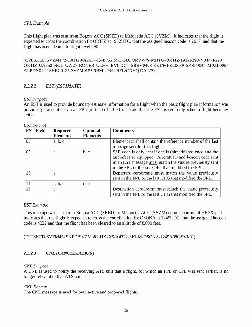
This flight plan was sent from Bogota ACC (SKED) to Maiquetia ACC (SVZM). It indicates that the flight is expected to cross the coordination fix ORTIZ at 1932UTC, that the assigned beacon code is 2617, and that the flight has been cleared to flight level 290.
(CPLSKED/SVZM172-TAI128/A2617-IS-B752/M-DGIJLORVW/S-MHTG-ORTIZ/1932F290-N0447F290 ORTIZ UA552 NOL UW27 RONER UL304 BVI DCT-SBBV0403-EET/MPZL0039 SKSP0044 MPZL0054 ALPON0122 SKEC0135 SVZM0157 SBMU0344 SEL/CDHQ DAT/S)
2.3.2.2 EST (ESTIMATE)
EST Purpose An EST is used to provide boundary estimate information for a flight when the basic flight plan information was previously transmitted via an FPL (instead of a CPL). Note that the EST is sent only when a flight becomes active. EST Format EST Field Required
Elements Optional Elements
Comments
03 a, b, c Element (c) shall contain the reference number of the last message sent for this flight.
07 a b, c SSR code is only sent if one is (already) assigned and the aircraft is so equipped. Aircraft ID and beacon code sent in an EST message must match the values previously sent in the FPL or the last CHG that modified the FPL.
13 a Departure aerodrome must match the value previously sent in the FPL or the last CHG that modified the FPL.
14 a, b, c d, e 16 a Destination aerodrome must match the value previously
sent in the FPL or the last CHG that modified the FPL. EST Example
This message was sent from Bogota ACC (SKED) to Maiquetia ACC (SVZM) upon departure of HK2X5. It indicates that the flight is expected to cross the coordination fix OSOKA at 1245UTC, that the assigned beacon code is 4322 and that the flight has been cleared to an altitude of 8,000 feet.
(ESTSKED/SVZM452SKED/SVZM381-HK2X5/A4322-SKLM-OSOKA/1245A080-SVMC)
2.3.2.3 CNL (CANCELLATION)
CNL Purpose A CNL is used to notify the receiving ATS unit that a flight, for which an FPL or CPL was sent earlier, is no longer relevant to that ATS unit. CNL Format The CNL message is used for both active and proposed flights.

CAR/SAM ICD - Draft version 0.2
21
2.3.2.4 MOD (MODIFY MESSAGE FOR ACTIVE FLIGHT PLAN)
MOD Purpose A MOD is used to transmit a change to one or more fields of previously sent flight data after boundary estimate data has been sent. The MOD is therefore used for any flight data changes after a CPL or an EST has been sent. MOD Format MOD Field Required
Elements Optional Elements
Comments
03 a, b, c Element (c) shall contain the reference number of the first message sent for this flight.
07 a b, c SSR code is only sent if one is (already) assigned or the aircraft is so equipped. Fields 07, 13, and 16 must contain the values of these fields before the flight data was changed.
13 a 16 a
22 a, b MOD Example
This amendment removes the RVSM capability from field 10 and changes the assigned altitude to flight level 240.
(MODSKED/SVZM218SKED/SVZM172-TAI128-MHTG-SBBV-10/DGIJLORV/S-15/N0447F240 UA552 NOL UW27 RONER UL304 BVI DCT)
2.3.3 GENERAL INFORMATION MESSAGES
2.3.3.1 MIS (MISCELLANEOUS)
MIS Purpose A MIS is used to transmit a free text message to a specific functional position, or to the position responsible for a specific flight, at another facility. MIS Format MIS Field Required
Elements Optional Elements
Comments
03 a, b 07 a Note that element (a) in the MIS may contain a flight ID
or a functional address 18 RMK/
followed by free text

CAR/SAM ICD - Draft version 0.2
22
MIS Example
In this example, Bogota ACC (SKED) informs Maiquetia ACC (SVZM) that TACA flight 128 has lost its RVSM capability.
(MISSKED/SVZM221-TAI128-RMK/TACA128 HAS LOST RVSM CAPABILITY)
2.3.4 INTERFACE MANAGEMENT MESSAGES
2.3.4.1 IRQ (INITIALIZATION REQUEST)
IRQ Purpose An IRQ is used to request transition of an interface from a non-operational to an operational state. IRQ Format IRQ Field Required
Elements Optional Elements
Comments
03 a, b IRQ Example
In this example, Bogota ACC (SKED) has sent a request to Maiquetia ACC (SVZM) to initialize the interface.
(IRQSKED/SVZM266)
2.3.4.2 IRS (INITIALIZATION RESPONSE)
IRS Purpose An IRS is used as a response to an IRQ message. IRS Format IRS Field Required
Elements Optional Elements
Comments
03 a, b, c Element (c) should contain the reference number of the previously sent IRQ.
IRS Example
In this example, Maiquetia ACC (SVZM) has responded to Bogota ACC's (SKED) request to initialize the interface.
(IRSSVZM/SKED817SKED/SVZM266)

CAR/SAM ICD - Draft version 0.2
23
2.3.4.3 TRQ (TERMINATION REQUEST)
TRQ Purpose A TRQ is used to request transition of an interface from an operational to a non-operational state. TRQ Format TRQ Field Required
Elements Optional Elements
Comments
03 a, b 18 a, other info. Element (a) is included only if no other information is
included. Either element (a) OR other information (but not both) must be included. Other information, if included, must include RMK/ followed by free text.
TRQ Example
In this example, Bogota ACC (SKED) has sent a request to Maiquetia ACC (SVZM) to terminate the interface.
(TRQSKED/SVZM348)
2.3.4.4 TRS (TERMINATION RESPONSE)
TRS Purpose TRS is used as a response to an TRQ message. TRS Format TRS Field Required
Elements Optional Elements
Comments
03 a, b, c Element (c) should contain the reference number of the previously sent TRQ.
18 a, other info. Element (a) is included only if no other information is included. Either element (a) OR other information (but not both) must be included. Other information, if included, must include RMK/ followed by free text.
TRS Example
In this example, Maiquetia ACC (SVZM) has responded to Bogota ACC's (SKED) request to initialize the interface.
(TRSSVZM/SKED912SKED/SVZM348)

CAR/SAM ICD - Draft version 0.2
24
2.3.5 ACKNOWLEDGEMENTS
2.3.5.1 LAM (LOGICAL ACKNOWLEDGEMENT)
LAM Purpose An LAM is sent from ACC to ACC to indicate that a message has been received and found free of syntactic and semantic errors. It does not indicate operational acceptance by a controller. Element (c) contains the reference number (i.e. element 3(b)) of the message being responded to. LAM Format LAM Field Required
Elements Optional Elements
Comments
03 a, b, c LAM Example
In this example, Maiquetia ACC (SVZM) has accepted message number 739 from Bogota ACC (SKED).
(LAMSVZM/SKED629SKED/SVZM739)
2.3.5.2 LRM (LOGICAL REJECTION)
LRM Purpose An LRM is used to indicate that a message sent from ATS system to ATS system contained an error and has been rejected by the receiving system. LRM Format LRM Field Required
Elements Optional Elements
Comments
03 a, b, c 18 text as shown
in Comments Describes the error code and the error per Appendix A
guidelines: after RMK/, include two digits comprising the error code; (note that error code 57 will be used for any error that is not field specific and that is not identified in Appendix A - Error Codes) two digits comprising the field in error (or 00 if the error is not field-specific); and the erroneous text, i.e. the contents of the message that caused the error when the error is field specific. When the error is non-field specific, a descriptive error message shall be included. Separate the above items by an oblique stroke (/).
LRM Example
In this example, Maiquetia ACC (SVZM) has rejected message number 392 from Bogota ACC (SKED) because the aircraft identification in field 7 of message 392 was too long.
(LRMSVZM/SKED519SKED/SVZM392-RMK/06/07/TACA1745)

CAR/SAM ICD - Draft version 0.2
25
2.3.6 RADAR HANDOVER MESSAGES
2.3.6.1 RTI MESSAGE (RADAR TRANSFER INITIATE)
RTI Purpose An RTI message is sent from one ATS unit to another to initiate the transfer of radar identification for a flight. Logical acknowledgement of an RTI is an RLA or LRM. RTI Format RTI Field Required
Elements Optional Elements
Comments
03 a, b, c 07 a, b, c Must include ACID and established SSR code 13 a 16 a 31 a a If no sector designated or sector 00 is designated, then
receiving system determines 32 a, b, c, d, e
RTI Examples This is an example of a handover initiated by Merida ACC to Cenamer ACC. No sector is designated, so Cenamer will determine who should receive it. (RTIMMMD/MHTG812MMMD/MHTG801-TAC210/A3407-MMMX–MPTO–MHTG -13242934162000N0912401WN043327629F349) This is an example of a handover directed to sector 01 in Cenamer ACC, from Merida ACC. (RTIMMMD/MHTG812MMMD/MHTG801-TAC210/A3407-MMMX–MPTO–MHTG01 -13242934162000N0912401WN043327629F349)
2.3.6.2 RLA MESSAGE (RADAR LOGICAL ACKNOWLEDGEMENT)
RLA Purpose The Radar Logical Acknowledgment message is used to acknowledge computer receipt of an RTI message. The facility sending this message is indicating that the referenced message has been received and has no format or logic errors, and to indicate which sector the handover was routed to. The RLA is an acknowledgement message in response to RTI and therefore is not responded to. RLA Format RLA Field Required
Elements Optional Elements
Comments
03 a, b, c 31 a, b

CAR/SAM ICD - Draft version 0.2
26
RLA Examples In this example Cenamer ACC has indicated to Merida ACC that it has received a handover and routed it to sector 01. (RLAMHTG/MMMD202MHTG/MMMD445-MHTG01) In this example Cenamer ACC has indicated to Merida ACC that it has received a handover and routed it to the Guatemala Radar Approach Control (RLAMHTG/MMMD202MMMD/MHTG445-MGGT)
2.3.6.3 RTU MESSAGE (RADAR TRACK UPDATE)
RTU Purpose An RTU message may be sent from one ATS unit to another to update the radar position of a flight during transfer of radar identification. RTU messages are sent periodically after an RTI, until an RTA is received or the handover is retracted. There is no logical acknowledgement of an RTU. RTU Format RTU Field Required
Elements Optional Elements
Comments
03 a, b, c Element (c) shall refer to the message number of the RTI message that initiated the handover.
07 a ,b ,c Include established SSR code. 13 a 16 a 32 a, b, c, d, e
RTU Examples This is an example of an RTU message initiated by Cenamer ACC to Merida ACC. The message MHTG/MMMD801 was the RTI message that initiated the handover. (RTUMHTG/MMMD000MHTG/MMMD801-TAC211/A3407-MPTO-MMMX -13242934154412N0905100WN043327629F341)
2.3.6.4 RTA MESSAGE (RADAR TRANSFER ACCEPT)
RTA Purpose An RTA message may be sent from one ATS unit to another as an application response to an RTI. This message signifies that a controller has accepted radar identification of a flight. An RTA is also sent by the facility that initiated a handover to retract the handover. Logical (computer) acknowledgement of an RTA is an LAM or LRM.

CAR/SAM ICD - Draft version 0.2
27
RTA Format RTA Field Required
Elements Optional Elements
Comments
03 a, b, c Element (c) refers to the message number of the RTI that is being responded to.
07 a, b, c Include assigned SSR code (i.e. code assigned by the accepting center).
13 a 16 a 31 a, b Note accepting facility may be a Radar Approach Control
serviced by the sending ACC. RTA Examples This is an example of a handover accepted by Merida ACC. Handover was initiated by Cenamer ACC. (RTAMMMD/MHTG438MHTG/MMMD812-TAC211/A4222-MPTO-MMMX-MMMD01) This is an example of a retraction by Cenamer ACC: (RTAMHTG/MMMD222MHTG/MMMD812-TAC211/A4222-MPTO-MMMX-MHTG01)

CAR/SAM ICD - Draft version 0.2
28
3. PART III – COMMUNICATIONS AND SUPPORT MECHANISMS
3.1 INTRODUCTION
The communications protocols and physical path are not dictated by this ICD. This ICD addresses only the application message content.
3.2 TELECOMMUNICATIONS REQUIREMENTS AND CONSTRAINTS
Telecommunication requirements and constraints should be carried out bilaterally or multilaterally and incorporated into applicable bilateral or multilateral agreements.
3.2.1 USE OF AERONAUTICAL FIXED TELECOMMUNICATIONS NETWORK (AFTN)
AFTN may be used as a flight plan data interface, subject to verification of performance. Any interface exchanging radar position data, including radar handovers, shall not use AFTN. When AFTN is used as the communications mechanism: a) The AFTN IA-5 Header as described in ICAO Annex 10, vol. 2 will be used for exchange of
messages. b) ATS messages will be addressed to each ATS unit using an eight-character facility address
where the first four characters are the appropriate location indicator from ICAO Doc 7910, and the last four characters are routing indicators defined by the ATS unit in accordance with ICAO Annex 10, vol. 2.
Each message shall be sent with the priority indicated in Table 2 of Part II.
3.2.2 USE OF A WIDE-AREA NETWORK
Use of existing wide-area networks (e.g. X.25 or Frame Relay packet-switched network) may be used if the speed, capacity, and security characteristics are verified as adequate to support the interface.
3.2.3 USE OF DIRECT LINES
In cases where speed, capacity, and/or security require it, a direct line interface may be used between facilities.
3.2.4 CHARACTER SET
The IA-5 character set shall be used for all application message content. Certain characters have special meaning and must only be used as indicated below: Open parenthesis “(”and close parenthesis “)” shall be used only to begin and terminate the application message. A single hyphen “-” shall be used only as a field separator and shall not be used within any field.
CAR/SAM ICD - Draft version 0.2
29
3.3 ENGINEERING CONSIDERATIONS
3.3.1 ASSOCIATED AUTOMATION FUNCTIONALITY
Each ATS service provider participating in this interface must have a supporting automation system. The supporting automation shall:
Error check all inbound messages for proper format and logical consistency.
Ensure only messages from authorized senders are accepted and processed.
As required, alert the responsible controller(s) of flight data that has been received.
Notify the responsible personnel when any message sent is rejected or not acknowledged within a variable system parameter (VSP) period of time (see 4.5.1 Response time).
3.3.2 FAILURE AND RECOVERY SOLUTIONS
Automation systems may have different failure avoidance and failure recovery mechanisms. Each participating system shall have the following characteristics:
If the recovery process preserves the current message number in the sequence with each facility, no notification is necessary.
If the recovery process requires reset of the sequence number to 000, a means of notifying the receiving
facility that the message numbers have been reset is required. This may be procedural rather than automated.
The recovery process shall not automatically re-send any CPL for which an LAM had been received. This is relevant if the system was able to recover state information about which flight plans have been coordinated, and did not need to reset the message sequence numbers.
3.3.3 DATA REQUIREMENTS
Certain data must be defined and maintained to support all features of the interface. Depending on the data, it should be coordinated on a Regional, National, or Local (facility) basis. Data requirements are identified in Table 3 below.

CAR/SAM ICD - Draft version 0.2
30
Table 3. Summary of Data Definitions Needed to Support the Interface Field Data Purpose Source Coordination 03 Facility Identifiers Identify the sending/receiving
facility. ICAO Doc 7910 (first four characters) and local definition (second four characters)
Local
07 Functional Address Agree on functional addresses to be used in MIS messages.
Local Data Local
10 Equipment Codes Identify ATS-specified equipment qualifiers that are not specified in ICAO Doc 4444.
ICAO Doc 7030 CAR and SAM Supplements
Regional
14 Boundary Point Identify the coordination fixes to be sent for each airway.
Local Data Local
15 Adapted Routes and Fixes
Identify airway and fix information that is adapted by both systems.
Local Data Local
18 Requirements for other data to be included
Identify any requirements for data that must be included in Field 18.
ICAO Doc 7030 CAR and SAM Supplements
Regional
3.4 SECURITY CONSIDERATIONS
3.4.1 PRIVACY
This ICD does not define mechanisms that guarantee privacy. It should be assumed that any data sent over this interface may be seen by unintended third parties either through interception of the message or through disclosure at the receiving facility. Any communications requiring privacy must be identified and appropriate communications and procedures defined.
3.4.2 AUTHENTICATION
Each system shall authenticate that messages received are from the source that is identified in Field 03.
3.4.3 ACCESS CONTROL
Each system participating in the interface shall implement eligibility checks to ensure that the source of the message is eligible to send the message type and is the appropriate authority for the referenced flight.
3.5 TEST CONSIDERATIONS
Before an automated flight data interface becomes operational between any two facilities, the following set of tests shall be completed:
CAR/SAM ICD - Draft version 0.2
31
Test of the telecommunications system and addressing: Off-line tests using development or test (i.e. non-operational) systems. These may include test systems at non-operational facilities, and/or operational systems that are in an off-line mode. Note: If off-line testing is not possible, extreme care should be used when conducting first round testing on operational systems.
Test of non-operational message sets:
Tests using the operational systems in off-line (recommended) or operational mode in which TEST messages are exchanged. (Note: If off-line testing is not possible, extreme care should be used when conducting second round testing on operational systems.)
Test of operational message sets:
Tests using the operational systems in operational mode in which manual coordination verifies each flight data message sent.
Before each test, a document specifying purpose, procedures and data to be collected, must be agreed to by both/all facilities. To ensure success/failure is clearly defined, specific criteria should be included in the document. Data transmitted during test phases should include both correct and incorrect formats/data fields to verify that correct data is processed correctly and incorrect data is rejected. For diagnostic purposes, each side of the interface should be able to isolate the source of interface problems.
3.6 PERFORMANCE CONSIDERATIONS
3.6.1 RESPONSE TIME
For flight planning messages, controllers require indication of an unsuccessful message transmission within 60 seconds of the message being sent. Therefore, the response time from the time a message is sent until an LAM (or LRM) is received shall be under 60 seconds at least 99% of the time under normal operations. A faster response time is desirable, and will result in operations that are more efficient. For messages involving transfer of control and surveillance data (e.g. RTI, RTA, and RTU) the data must be transmitted in time for the receiving system to display the track position with acceptable accuracy. Communication across the interface shall be less than six seconds maximum.
3.6.2 AVAILABILITY / RELIABILITY
The hardware and software resources required for providing service on the CAR/SAM interfaces should be developed such that the inherent reliability will support interface availability which is at least equal to the end systems of that interface (e.g. 99.7% availability for end systems that both operate with 99.7% reliability).

CAR/SAM ICD - Draft version 0.2
32
3.6.3 CAPACITY AND GROWTH
Before implementing this interface between two ACCs, an analysis of the traffic expected between the centers shall be performed and the proposed communications links verified for appropriate capacity. Traffic estimates should consider current and future expected traffic levels. For initial planning purposes the following estimates of message size and messages per flight are provided. Table 4. Expected Message Rates and Sizes
Message Avg. per
Flight Avg. Size
Max Size Comments
Messages per near-border departure flight: FPL 1 275 2,000
CHG 0.5 160 1,000 Assumed 1 of 2 flights amended after coordination, before departure.
EST 1 120 200
MOD 2 120 1,000 Assumed each flight has an average of one change after coordination due to amendment and two time updates.
Messages per non near-border departure flight:CPL 1 275 2,000
MOD 2 120 1,000 Assumed each flight has an average of one change after coordination due to amendment and two time updates.
Messages per every flight: CNL 0.01 100 150 Assumed 1 in 100 flight plans are cancelled. RTI 1 150 200 RTU 5 140 200 Assumed 1 RTU every 6 seconds for 30 seconds. RTA 1 110 160 MIS 0.1 130 625 Responses (not per flight):
LAM/RLA
Sum of all above except RTU
80 130
LRM 100 230
The hardware and software developed for the interfaces shall be capable of asynchronously exchanging the messages defined in Part III, Table 2 simultaneously with all adjacent automated systems.

CAR/SAM ICD - Draft version 0.2
A-1
APPENDIX A – ERROR CODES The error codes for use with LRM messages are defined in Table A-1 below. Table A-1. LRM Error Codes and Explanations
Error Code
Field Number Supporting Text
1 Header INVALID SENDING UNIT (e.g., AFTN address) 2 Header INVALID RECEIVING UNIT (e.g., AFTN address) 3 Header INVALID TIME STAMP 4 Header INVALID MESSAGE ID 5 Header INVALID REFERENCE ID 6 07 INVALID ACID 7 07 DUPLICATE ACID 8 07 UKNOWN FUNCTIONAL ADDRESS 9 07 INVALID SSR MODE 10 07 INVALID SSR CODE 11 08 INVALID FLIGHT RULES 12 08 INVALID FLIGHT TYPE 13 09 INVALID AIRCRAFT MODEL 14 09 INVALID WAKE TURBULENCE CATEGORY 15 10 INVALID CNA EQUIPMENT DESIGNATOR 16 10 INVALID SSR EQUIPMENT DESIGNATOR 17 13, 16 INVALID AERODROME DESIGNATOR 18 13 INVALID DEPARTURE AERODROME 19 16 INVALID DESTINATION AERODROME 20 17 INVALID ARRIVAL AERODROME 21 13, 16 EXPECTED TIME DESIGNATOR NOT FOUND 22 13, 16 TIME DESIGNATOR PRESENT WHEN NOT EXPECTED 23 13, 14, 16 INVALID TIME DESIGNATOR 24 13, 14, 16 MISSING TIME DESIGNATOR 25 14 INVALID BOUNDARY POINT DESIGNATOR 26 14, 15 INVALID ENROUTE POINT 27 14, 15 INVALID LAT/LON DESIGNATOR 28 14, 15 INVALID NAVAID FIX 29 14, 15 INVALID LEVEL DESIGNATOR 30 14, 15 MISSING LEVEL DESIGNATOR 31 14 INVALID SUPPLEMENTARY CROSSING DATA 32 14 INVALID SUPPLEMENTARY CROSSING LEVEL 33 14 MISSING SUPPLEMENTARY CROSSING LEVEL 34 14 INVALID CROSSING CONDITION 35 14 MISSING CROSSING CONDITION 36 15 INVALID SPEED/LEVEL DESIGNATOR 37 15 MISSING SPEED/LEVEL DESIGNATOR 38 15 INVALID SPEED DESIGNATOR 39 15 MISSING SPEED DESIGNATOR 40 15 INVALID ROUTE ELEMENT DESIGNATOR 41 15 INVALID ATS ROUTE/SIGNIFICANT POINT DESIGNATOR 42 15 INVALID ATS ROUTE DESIGNATOR

CAR/SAM ICD - Draft version 0.2
A-2
Error Code
Field Number Supporting Text
43 15 INVALID SIGNFICANT POINT DESIGNATOR 44 15 FLIGHT RULES INDICATOR DOES NOT FOLLOW SIGNIFICANT POINT 45 15 ADDITIONAL DATA FOLLOWS TRUNCATION INDICATOR 46 15 INCORRECT CRUISE CLIMB FORMAT 47 15 CONFLICTING DIRECTION 48 18 INVALID OTHER INFORMATION ELEMENT 49 19 INVALID SUPPLEMENTARY INFORMATION ELEMENT 50 22 INVALID AMENDMENT FIELD DATA 51 MISSING FIELD nn 52 MORE THAN ONE FIELD MISSING 53 MESSAGE LOGICALLY TOO LONG 54 SYNTAX ERROR IN FIELD nn 55 INVALID MESSAGE LENGTH 56 NAT ERRORS 57 INVALID MESSAGE 58 MISSING PARENTHESIS 59 MESSAGE NOT APPLICABLE TO zzzz ACC 60 INVALID MESSAGE MNEMONIC (i.e., 3 LETTER IDENTIFIER) 61 Header INVALID CRC 62 MESSAGE REJECTED, MANUAL COORDINATION REQUIRED 63-255 Reserved for future use.
Error Code 57 shall be used for any error that is not field-specific and is not identified in the table. Each ATS provider may propose additional error codes as needed and submit them through the GREPECAS mechanism for approval and inclusion in this Table.

CAR/SAM ICD - Draft version 0.2
B-1
APPENDIX B – IMPLEMENTATION GUIDANCE MATERIAL
B.1 USE OF THE CORE MESSAGE SET
B.1.1 FILED FLIGHT PLAN (FPL) MESSAGES
A user must file a filed flight plan message (FPL) with the initial ATS unit that will service the flight as well as with the ATS unit for each FIR that the flight will cross. The format and content of this FPL is subject to the rules of the receiving country and is not defined by this ICD. It is expected that an FPL will be filed by an airspace user, and a subsequent CPL will be received from an adjacent ATS unit. It is the responsibility of each country to design their automation to ensure that an FPL or CPL from an adjacent ATS unit always takes precedence over a user-filed FPL for the flight so that second-order flight data messages are applied to the ATS unit-supplied flight plan and not the user-filed flight plan.
B.1.2 COORDINATION OF ACTIVE FLIGHTS (CPL)
Normally, an agreed upon number of minutes before a flight reaches a control boundary the sending ATS unit will send a CPL message to the receiving ATS unit. The normal computer response to a CPL is an LAM sent by the receiving automation system to signify that the plan was found to be free of syntactic or semantic errors. Controller acceptance is implied (i.e. the ACP message defined in ICAO Doc 4444 is not implemented). This is permitted per ICAO Doc 4444, Part IX, section 4.2.3.5.1 and Part VIII, section 3.2.5. If the receiving computer cannot process a CPL then an LRM will be returned if that message has been implemented. Alternatively, no response will be generated. ICAO Doc 4444 states, in Part IX, section 4.2.3.2.5 “A CPL message shall include only information concerning the flight from the point of entry into the next control area or advisory airspace to the destination aerodrome”. However ICAO Doc 4444 provides no guidelines for choosing the exact point at which the CPL should start. The nature of ATC automation systems is that they have differing requirements for the starting point of a route relative to the facility boundary, necessitating some agreement on allowable route tailoring. The relationship between the start of the route in Field 15 and the coordination fix in Field 14 must also be established so that the receiving center can accurately process the route. Agreements on these points are provided in the attached boundary agreements for each ATS provider.
B.1.3 CHANGES AFTER COORDINATION
Any change to a flight plan after initial coordination requires a message that can be mapped to the correct flight plan. Every message sent after an initial CPL should have the same Aircraft ID, departure point, and destination point. The message reference data should point to the previous message in the sequence for this flight. For example, if the CPL is message number KZMP/CZWG035 then the reference data for the first MOD sent after the CPL should be KZMP/CZWG035. The second MOD sent for that flight should refer to the message number of the original CPL.. The messages that represent valid changes to the original flight plan include CHG, EST, MOD, RTI, and RTA (when used for retraction; see Section B.1.8).

CAR/SAM ICD - Draft version 0.2
B-2
If a flight for which a CPL has been sent will no longer enter the recipient’s airspace, a CNL message should be sent. After acceptance of a CNL message, the receiving system should not accept any changes regarding the subject flight. Any change to flight data for a flight that has been coordinated (i.e. a CPL or EST has been sent) must be forwarded via a MOD message. The MOD message is identical to the ICAO CDN message in format and content, but does not require an ACP response (only LAM or LRM). The expected computer response to a CNL, CHG, EST, or MOD is an LAM or LRM (if the latter has been implemented). Each system should implement rules as to whether an amendment on a particular flight should be accepted from a neighboring ACC. For example, an amendment from the sending ACC typically is not accepted once transfer of control has been initiated. It is expected that the content of a field sent in a flight data change message (e.g. CHG or MOD) will completely replace the content of the field currently stored in the receiving center. So, for example, if Field 18 is amended the entire contents of the field should be sent and not only the changed elements. An aircraft placed into a hold should result in a MOD message being sent with new Field 14 Estimate Data (boundary time) based on the Expect Further Clearance (EFC) time. If no EFC time is established by ATC, an agreed upon default EFC time may be used (e.g. 2 hours) to ensure the flight plan data is maintained by the receiving facility. If necessary, a second MOD message should be sent with the revised Estimate Data time once it is known. Upon acceptance of an RTI message the receiving system should accept only an RTA, RTU, or MIS message for the flight. If an RTA signifying retraction is accepted, then the system may once again accept a MOD message. Upon receipt of a logical acknowledgement to an RTA message signifying handover acceptance, the sender of the RTA should not accept any messages regarding the subject flight.
B.1.4 NEAR-BORDER DEPARTURES
ATS units implementing automated coordination for near-border departures may also exchange FPLs to coordinate flights pre-departure when the flight time from the departure point to the boundary point is less than the normal CPL notification time. ATS units will send an FPL message pre-departure followed by an EST message upon departure. Additional coordination procedures may be defined in an inter-facility Letter of Agreement. If an FPL has been sent and changes are subsequently made, then a CHG message should be used to modify the changed fields. Only the ATS unit that sent an FPL message may send a CHG message (i.e. the receiving unit cannot send a CHG back to the sending unit). Once an EST message is sent, a MOD must be used instead of a CHG for transmission of flight data changes. The expected computer response to an FPL is an LAM or LRM. If a previously sent FPL is to be cancelled, a CNL message should be sent.

CAR/SAM ICD - Draft version 0.2
B-3
B.1.5 INTERFACE MANAGEMENT
ATS units implementing a data communications interface will nominally be expected to accept messages at any time when the system is available. Each system is responsible for providing the capability of inhibiting received messages, if needed. Each system is expected to be able to inhibit outgoing messages. Manual coordination between facilities may be needed for one facility to request the other to inhibit messages. ATS units which implement data communication interfaces may exchange messages to request initialization or termination of the interface via automated messages. Only when an initialization request has been sent and responded to affirmatively will each system be expected to accept messages. Any message received when the interface is not initialized shall be ignored (i.e. not processed and not responded to), except for IRQ. To request initialization one system shall send an IRQ message to the other. The IRQ may be repeated a predetermined number of times if no response is received, with each repeated IRQ receiving the same message number. If the receiving system is ready to communicate (i.e. it has already sent an IRQ) when it receives an IRQ, it shall send an IRS in response. There is no LAM or LRM response to an IRQ. The reference number in Field 03 should refer to the message number of the IRQ being responded to. Each system becomes active when it receives an IRS from the other system. There is no response to an IRS. If no response to an IRQ is received and the maximum number of retries exceeded, the interface is considered failed by the initiating system. A system requests orderly termination of the interface by sending a TRQ message. After sending a TRQ, a system shall accept only a TRS or TRQ message. There is no LAM or LRM response to a TRQ. Upon receipt of a TRS the interface shall be deactivated. There is no response to a TRS. Upon receipt of a TRQ the system shall respond with a TRS and deactivate the interface immediately (even if a TRQ is outstanding). When messages are exchanged between two ATS units that cause successful termination of the interface, the two systems shall not send or accept any messages on the interface until a successful initialization transaction has been completed.
B.1.7 ERROR CHECKING, RESPONSES, AND RESENDS
Upon receiving a message, the receiving system shall check that the format and content of each field are in accordance with this ICD. Other logic checks may be performed per the rules defined by the ATS provider. Whenever a message is received and passes all syntactic and semantic checks an LAM (or RLA for handover initiation) shall be returned to the sender for those messages designated for LAM/LRM responses. ATS units implementing only LAM acknowledgement messages will not send any response to the sender when a message fails a syntactic or semantic check. The sending ATS Unit must infer message rejection by failure to receive an LAM. Agreement on one minute as a maximum operationally acceptable time-out value (from the time a message is sent to receipt of an LAM) is recommended. ATS units implementing only LAM acknowledgement messages cannot productively use message resend as a technique, since the lack of an LAM may infer a lost message or message rejection. Therefore use of message resends after timeout of an LAM receipt is not recommended.

CAR/SAM ICD - Draft version 0.2
B-4
ATS units implementing both LAM and LRM acknowledgement messages will send an LRM when a received message fails a syntactic or semantic check, using the error codes in Appendix A. In the case of a radar handover initiation (see B.1.8) an RLA is used instead of an LAM. When no response to a message is received within a VSP period of time a unit may optionally choose to resend the original message—using the same message number—a VSP number of times before declaring failure. The same message number should be used so that the receiving station can easily distinguish exact duplicates should the same message be received more than once.
B.1.8 RADAR HANDOVERS
- RTI Message An RTI shall be used to initiate a transfer of radar identification from a controller in one ACC to a controller in another ACC. An RLA or LRM shall be returned in response to an RTI, based on acceptance checks by the receiving computer. If no logical response (RLA or LRM) to an RTI is received after a specified number of retries, the handover should be marked as failed to the initiating controller. Upon acceptance of an RTI message the receiving system should not accept any flight data messages regarding the subject flight except for an RTA, RTU, or MIS. - RTU Message The transferring center shall begin sending RTU messages once an RLA is received for an RTI. RTU messages shall be sent once every tracking cycle. The expected track update rate must be coordinated between the implementing countries. An RTU message should not be sent when current track data is not available for a flight, e.g. if the flight enters a coast mode. Upon retraction of the transfer or receipt of an RTA from the receiving center the sending of RTUs shall stop. There will be no response to an RTU (i.e. no LAM, RLA, or LRM). - RTA Message An RTA message shall be sent by the receiving center in response to an RTI when the receiving controller has accepted the transfer. An RTA message shall be sent by the sending center when the initiating controller retracts a previously issued RTI. An LAM or LRM shall be returned in response to an RTA, based on acceptance checks by the receiving computer. If no response is received within a VSP period of time (e.g. 6 seconds), the transfer shall be considered failed and the accepting controller notified. If the sending center receives an RTA after retracting a handover, it shall reject the RTA by returning an LRM. If the receiving center receives an RTA after accepting a handover, it shall reject the RTA by returning an LRM.

CAR/SAM ICD - Draft version 0.2
B-5
After an RTA is rejected, the controller that attempted to accept or retract control shall be notified that the handover failed. Note that it is possible for an accept and retract to be entered simultaneously, resulting in both RTA messages being rejected.
B.1.9 MIS MESSAGE
The MIS message can be addressed to either a functional address, or to an aircraft ID. The functional addresses to use will be exchanged between adjacent centers. Each functional address will map to a workstation or set of workstations, and the types of information that should be sent to each address should accompany the exchange of addresses. When an MIS message is addressed to a flight ID, the receiving system shall route the message to the sector that currently controls the flight. If no sector controls the flight the message shall be rejected. The intent is that an MIS message does not modify the flight record for the subject flight (i.e. it is not treated as an amendment to Field 18 for that flight).
B.2 DEVELOPMENT OF FIELD CONTENT
The following sections provide implementation notes on the expected semantic content of each field, how to generate the fields and how to interpret the fields.
B.2.1 FIELD 03
Each message sent to each interface should receive an incrementally higher number. Thus, a system must maintain a separate sequence for each facility with which it interfaces. The message following number 999 will be 000, and then the number sequence repeats. The message number in Field 03 and the Aircraft ID in Field 07 combined, must be unique for any CPL or FPL. A flight plan received that has the same message number and ACID as a previously received plan shall be rejected. Note that it is possible to have duplicate message numbers if the sending computer system fails and is restarted in a cold start mode (i.e. no previous state data is retained). In this case the message numbers would restart and may repeat. Implementers of the data communications interface should consider a check for out-of-sequence messages (i.e. a message received has a message number that is not one greater than the previous message number). Since messages may be resent if a response is not received within a VSP period of time, it may also be possible to receive a message more than once. Therefore implementers should consider a check for duplicate messages based on the message number. Any such checks should also consider the behavior after a system failure/restart.

CAR/SAM ICD - Draft version 0.2
B-6
B.2.2 FIELD 07 If the aircraft does not have Mode A capability, omit elements (b) and (c) and the preceding oblique stroke. Also omit these elements if the aircraft has Mode A capability but the SSR code is unknown (or not assigned). B.2.3 FIELD 09 When the aircraft type is “ZZZZ”, there may be no certificated maximum take-off weight. In this case the pilot and/or controller are expected to determine what the value should be per the ICAO guidelines and the estimated weight of the aircraft. Allowable values for the aircraft type should include any type designator in ICAO Doc 8643. Note that implementers may choose to validate the wake turbulence category based on the aircraft type, since these are published in ICAO Doc 8643. B.2.4 FIELD 10 Agreement on ATS-prescribed indicators is to be specified in the ICAO Doc 7030 CAR and SAM Supplements. B.2.5 FIELD 13 The aerodrome in Field 13 must match a location indicator in ICAO Doc 7910, or must match one that is agreed to per the relevant boundary agreement, or agreed to by the implementing facilities. (Note: Some States permit International flights to depart from other than international aerodromes. These aerodromes may not have location indicators in ICAO Doc 7910.) If ZZZZ or AFIL is used, then additional information should be present in Field 18 per ICAO Doc 4444. This ICD imposes no specific requirements on the content of DEP/. B.2.6 FIELD 14 Field 14(a) contains a Boundary Point, which is an agreed point on or near the control boundary. The boundary agreement between implementing ATS providers identifies any specific requirements governing the choice of boundary point. B.2.7 FIELD 15 A CPL, per ICAO Doc 4444 Part IX, Section 4.2.3.2.5 “shall include only information concerning the flight from the point of entry into the next control area or advisory airspace to the destination aerodrome”. In practical terms, each automation system generally has restrictions on the starting point of the route. Each boundary agreement will define where the route of flight shall begin so as to meet the above requirement. After the initial point, Field 15(c) should contain the remainder of the route of flight.
B.2.8 FIELD 18

CAR/SAM ICD - Draft version 0.2
B-7
In an FPL or CPL, all Field 18 content must be delimited by elements constructed as shown in ICAO Doc 4444, each of which is a three to four-letter identifier followed by an oblique stroke. Field 18 shall not contain the character “-”, which is used to delineate fields in the message. When used in an LRM, only the RMK/ element should be identified; only the text of the rejection message shall be included.
B.3 SUMMARY OF EXPECTED RESPONSES TO MESSAGES
Table B-1 identifies the expected responses to each message. The computer logical responses represent acceptance or rejection based on computer checks for message validity. An application response is a response that is initiated by a person or the application software to provide semantic response to a message. Note that an LRM can be sent in response to a message with no computer response identified if the message ID (e.g. RTU) cannot be determined by the receiving computer. Table B-1. Summary of Expected Message Responses
Msg Computer Logical Response
Application Response
Msg Computer Logical Response
Application Response
Accept Reject Accept Reject
FPL LAM LRM None RTI RLA LRM RTA
CHG LAM LRM None RTU None None None
EST LAM LRM None RLA None None None
CPL LAM LRM None RTA LAM LRM None
CNL LAM LRM None LAM None None None
MOD LAM LRM None LRM None None None
MIS LAM LRM None
IRQ None None IRS
IRS None None None
TRQ None None TRS
TRS None None None

CAR/SAM ICD - Draft version 0.2
C-1
APPENDIX C – MODEL OF COMMON BOUNDARY AGREEMENT
C.1 INTRODUCTION
This section documents the data communications interface planned between (…XXX and XXX...) automation systems. The initial interface may have limited message capability. Future evolutions may include additional messages.
C.2 MESSAGE IMPLEMENTATION AND USE
C.2.1 MESSAGES IMPLEMENTED
The data communications interface between the (…XXX and XXX...) automation systems will include CPL and LAM. A CPL will be sent when a flight departs, or when it is within a VSP flying time from the boundary, whichever occurs later. Each CPL that is received and successfully checked for syntactic and semantic correctness will be responded to with an LAM.
C.2.2 ERROR HANDLING
An LAM will be sent in response to each CPL unless the receiving automation system detects an error. The automation system that sent the CPL will wait a VSP period of time for an LAM, and if none is received within the time parameter, it will notify the appropriate position that a failure occurred. Automatic retransmission of the message will not be attempted.
C.2.3 CHANGES TO A CPL
All changes to a previously sent CPL will be coordinated manually between the sending and receiving sectors.
C.2.4 FIELD 08, FLIGHT RULES AND TYPE OF FLIGHT
Regardless of the value in Field 08(a), all CPLs sent on this interface will be assumed to be IFR at the boundary between (…XXX and XXX...) airspace. Each center is only to send flight plans for flights that are IFR at the boundary.
C.2.5 FIELD 09, NUMBER AND TYPE OF AIRCRAFT AND WAKE TURBULENCE CATEGORY
When a specific aircraft type is used, the wake turbulence indicator sent to (XXX) must match the value stored for the aircraft type in the (XXX) database. When “ZZZZ” is used as the aircraft type, the wake turbulence category may be H, M, or L as appropriate.

CAR/SAM ICD - Draft version 0.2
C-2
C.2.6 FIELD 13, DEPARTURE AERODROME AND TIME
Field 13(b), normally only present in FPLs, will be allowed as an optional element for CPLs on this interface. (XXX) expects to include this element in messages; the (XXX) does not.
C.2.7 FIELD 14, ESTIMATE DATA
If a flight is on an adapted route segment when it crosses the control boundary, Field 14(a) will reference the last significant point in the sending center’s airspace. If a flight is on a direct route segment when it crosses the control boundary Field 14(a) will reference the last significant point in the sending center’s airspace. If there is no significant point between the departure aerodrome and the boundary, the departure aerodrome will appear in Field 14(a). All flights are expected to cross the boundary in level flight, at the altitude in Field 14(c). Elements (d) and (e) will not be used, and manual coordination will be required for any flight not in level flight at the boundary.
For flights from ….. to …..: If a flight is on an adapted route segment when it crosses the control boundary, Field 14(a) will reference the first significant point in the receiving center’s airspace. If a flight is on a non-adapted direct route segment when it crosses the control boundary Field 14(a) will reference the intersection of the route with the control boundary.
C.2.8 FIELD 15, ROUTE
Element type (c6) will not be used on this interface. Element 15(c) will be constructed the same way whether the flight is from ….or from ….: If a flight is on an adapted route segment when it crosses the control boundary then Field 15(c) will begin with the same significant point as is in Field 14(a). If a flight is on a direct route segment when it crosses the control boundary then Field 15(c) will begin with the last significant point in the sending center’s airspace, if one exists. If there is no significant point between the departure aerodrome and the boundary then Field 15(c) will begin with “DCT”. After the initial point, Field 15(c) will contain the remainder of the route of flight.
C.2.9 FIELD 16, DESTINATION AERODROME AND TOTAL ESTIMATED ELAPSED TIME, ALTERNATE AERODROME(S)
Fields 16(b) and (c), normally only present in FPLs, will be allowed as optional elements on this interface.

CAR/SAM ICD - Draft version 0.2
C-3
C.3 PHYSICAL INTERFACE
Messages will be exchanged across this interface between the following facilities: …Center to … …Center to ….
VancouverCZVR
SeattleKZSE
Salt LakeCity
KZLC
WinnipegCZWG
MinneapolisKZMP
TorontoCZYZ
MontrealCZUL
MonctonCZQM
NavCanadaTechnicalSystemsCentre
FAAWJHTC
EdmontonCZEG
AnchoragePAZA
ClevelandKZOB
TrentonMTCU
BostonKZBW
Ottawa TCU
Figure 1. Expected FAA/NAV CANADA Interfaces Governed by this ICD
- END/FIN -

AIDC/1-NE/02 APÉNDICE B
OrganizacióndeAviaciónCivilInternacional
RegiónSAM
GUÍA PARA LA IMPLANTACIÓN
DE AIDC
A TRAVÉS DE LA INTERCONEXIÓN
DE
CENTROS AUTOMATIZADOS ADYACENTES
Lima, Perú – Febrero Abril 20163

ii
Índice
REFERENCIAS .............................................................................................................. - 1 - OBJETO ........................................................................................................................... - 2 - 1. GENERALIDADES ................................................................................................ - 3 - 1.1. Introducción ...................................................................................................... - 3 - 1.2 Capacidad y crecimiento .................................................................................. - 4 - CAPÍTULO II. ................................................................................................................. - 5 - 2. ASPECTOS TÉCNICOS PARA LA IMPLANTACIÓN DEL AIDC ENTRE
SISTEMAS AUTOMATIZADOS ADYACENTES ............................................ - 5 - 2.1. Introducción ............................................................................................................. - 5 - 2.2. Consideraciones de comunicaciones para la interconexión de Centros
Automatizados. ................................................................................................ - 6 - Tipo ............................................................................................................................ - 6 - Datos .......................................................................................................................... - 6 - Formato ...................................................................................................................... - 6 - Identidad del mensaje ................................................................................................ - 6 - Definición del mensaje .............................................................................................. - 6 - Velocidad de los datos ............................................................................................... - 6 - Conexión física .......................................................................................................... - 6 - Características eléctricas ........................................................................................... - 6 - Data bits, parity, stop bits, protocol ........................................................................... - 6 -
2.3. Fases a tener en cuenta para la implementación del AIDC entre Centros Automatizados Adyacentes entre Estados .................................................... - 9 -
2.4. Confeccionar el memorando de entendimiento entre los Estados .............. - 10 - 2.5. Previsión de conectividad entre servidor AMHS ó CCAM AFTN ó canal
dedicado y el sistema automatizado ............................................................ - 10 - 2.6. Establecer la conectividad física y lógica entre los Estados ........................ - 12 - 2.7. Escenarios posibles. ........................................................................................ - 14 - 2.8. Crear las cuentas de usuario (mailbox) AMHS ó AFTN requeridas ......... - 17 - 2.9. Comprobar las cuentas de usuario ................................................................ - 19 - 2.10. Incorporar las cuentas de usuario a los sistemas automatizados que soportan
AIDC .............................................................................................................. - 20 - 2.11. Establecer un protocolo de pruebas .............................................................. - 20 - 2.12. Realizar pruebas pre-operacionales .............................................................. - 20 - 2.13. Realizar pruebas operacionales ..................................................................... - 21 - 2.14. Establecer y definir etapas de operación definitiva ..................................... - 21 - 2.15. Funcionalidad de automatización asociada .................................................. - 21 - 2.16. Soluciones o recomendaciones en caso de fallas o recovery ........................ - 22 - 2.17. Consideraciones de Seguridad ....................................................................... - 22 -
2.17.1. Privacidad ............................................................................................. - 22 - 2.17.3. Autenticación ........................................................................................ - 23 - 2.17.4. Control de Acceso ................................................................................ - 23 -
2.18. Consideraciones de performance .................................................................. - 23 - 2.19. Disponibilidad y fiabilidad ...................................................................... - 25 -
CAPÍTULO III. ............................................................................................................. - 26 -

iii
3. ASPECTOS OPERATIVOS PARA LA IMPLANTACIÓN DEL AIDC ENTRE SISTEMAS AUTOMATIZADOS ADYACENTES .......................................... - 26 -
3.1. Introducción .................................................................................................... - 26 - 3.2. Carta de acuerdo operacional ........................................................................ - 26 - 3.3. Set mínimo de mensajes AIDC ...................................................................... - 27 - 3.4. Procedimientos AIDC ..................................................................................... - 28 -
3.4.1. Etapa de notificación ............................................................................... - 28 - 3.4.2. Etapa de coordinación ............................................................................. - 28 - 3.4.3. Etapa de negociación ............................................................................... - 29 - 3.4.4. Etapa de transferencia ............................................................................ - 30 -
3.5. Diagrama de flujo ........................................................................................... - 31 - 3.6. Fases para las pruebas de implementación .................................................. - 32 -
3.6.1. Primera fase ............................................................................................. - 32 - 3.6.2. Segunda fase ............................................................................................. - 32 - 3.6.3. Tercera fase .............................................................................................. - 33 - 3.6.4. Cuarta fase ............................................................................................... - 33 -
APÉNDICE A ................................................................................................................ - 34 - COMPOSICIÓN DE LOS MENSAJES ATS ............................................................. - 34 - Campos de los mensajes ATS ....................................................................................... - 34 - FPL (plan de vuelo presentado) ................................................................................... - 35 - ABI (mensaje de notificación) ...................................................................................... - 35 - CPL (plan de vuelo actualizado) .................................................................................. - 36 - EST (estimaciones) ........................................................................................................ - 37 - CDN (mensaje de negociación) ..................................................................................... - 37 - ACP (mensaje de aceptación) ....................................................................................... - 38 - RJC (mensaje de rechazo) ............................................................................................ - 38 - TOC (mensaje de trasferencia) .................................................................................... - 38 - AOC (asumida la transferencia) .................................................................................. - 38 - LAM (acuse de recibo lógico) ....................................................................................... - 39 - LRM (rechazo lógico) .................................................................................................... - 39 - LISTA DE ACRONIMOS ............................................................................................ - 40 -

iv
Índice de tablas Tabla 1. Configuración CH AFTN ................................................................................. - 6 - Tabla 2. Direcciones AFTN/AMHS ............................................................................. - 18 - Tabla 3. Requisitos de rendimiento ............................................................................. - 24 - Tabla 4. Set de mensajes ATC ...................................................................................... - 27 - Índice de gráficos Gráfico 1. Muestra un entorno AFTN/AMHS (fuente Skysoft) .................................. - 7 - Gráfico 2. Visualización de los canales de un administrador del Gateway de SAEZ…..- 8 - Gráfico 3. Muestra esquemáticamente la función del gateway ................................... - 9 - Gráfico 4. Escenarios posibles de conectividad de última milla ................................ - 11 - Gráfico 5. Representación del caso en el cual el nodo de telecomunicaciones de acceso y
egreso de mensajes aidc se encuentra alejado al centro automatizado ........... - 12 - Gráfico 6. Integración de los usuarios AIDC de Centros Adyacentes ...................... - 13 - Gráfico 7.Referencia de acuerdo al modelo OSI ........................................................ - 14 - Gráfico 8. Aquí se muestra la comprobación de traslación de direcciones. ............. - 15 - Gráfico 9. Ejemplo topología AIDC con IPv4 REDDIG SAM .................................. - 16 - Gráfico 10. Configuración de la cuenta AIDC en el Sist. AMHS .............................. - 19 - Gráfico 11. Configuración de la cuenta CADI en el Sist. AMHS .............................. - 19 - Gráfico 12. Configuración AIDC ................................................................................. - 26 -

- 1 -
REFERENCIAS
Document ID Nombre documento Doc. 4444 OACI Gestión del Tránsito Aéreo
Annex 10, Volume II OACI
Telecomunicaciones Aeronáuticas
Annex 11 OACI Servicios de Tránsito Aéreo Doc. 9694 OACI Manual de los Servicios de Tránsito Aéreo –
Aaplicaciones de enlace de datos de los servicios de tránsito aéreo
Doc. 9880 OACI Manual de las especificaciones técnicas detalladas para la red de telecomunicaciones aeronáuticas (ATN) utilizando normas y protocolos ISO / OSI PARTE II -– Ground Ground ApplicationsAir Traffic Servies Message Handling Services (ATSMHS) Aplicaciones Tierra-Tierra entre instalaciones ATS de comunicaciones de datos (AIDC)
CAR/SAM/ICD Interface Control Document for Data Communications between ats units in the Caribbean and South American Regions
Doc. NAT/APAC ICD Pan Regional (NAT and APAC) Interface Control
Document for ATS Interfacility Data Communications (PAN AIDC ICD) - Version 1.0 — September 2014

- 2 -
OBJETO El presente documento tiene como objeto ser una guía de orientación práctica para la implantación del AIDC entre dos centros adyacentes automatizados de la Región SAM. La confección del presente documento para la implantación del AIDC y su interconexión, se encuentra previsto en el marco de las actividades del Proyecto Regional RLA/06/901, Asistencia para la implantación de un sistema regional de ATM considerando el concepto operacional de ATM y el soporte de tecnología en comunicaciones, navegación y vigilancia (CNS) correspondiente. El presente documento servirá de apoyo a los Estados de la Región a la hora de implantar AIDC a través de la interconexión de sistemas automatizados entre ACC adyacentes, y su elaboración fue considerada en el Decimo Taller/Reunión del Grupo de Implantación SAM (SAM/IG/10), llevado a cabo en Lima del 1 al 5 de octubre de 2012 y aprobada por la Sexta Reunión de Coordinación del Proyecto RLA/06/901 (Lima, 21 al 23 de noviembre de 2013). ALCANCE Los dos aspectos fundamentales que contiene el presente documento para la implantación del AIDC son: Aspectos técnicos. Aspectos operacionales. Estos aspectos implementados en un entorno de centros automatizados adyacentes.

- 3 -
CAPÍTULO I. 1. GENERALIDADES 1.1. Introducción 1.1.1. Una de las claves del futuro sistema de gestión de tráfico aéreo reside en el
intercambio bidireccional de datos entre la aeronave y el sistema ATC, y entre los sistemas ATC. Las comunicaciones con las aeronaves tiende cada vez más al empleo de enlace de datos digitales. Al mismo tiempo, el intercambio automático de datos entre los sistemas ATC apoyará la difusión oportuna de los datos de vuelo pertinentes, en particular en lo que se refiere a la coordinación y transferencia de vuelos entre dependencias ATS.
1.1.2. La aplicación AIDC deberá proporcionar importantes beneficios que incluyen:
a) Reducción de la carga de trabajo de los controladores;
b) Reducción de errores de colación / re-escucha durante la coordinación;
c) Reducción de errores groseros/crasos de navegación y las grandes desviaciones de altitud que son el resultado de "controlador del controlador" errores de coordinación
d) Reemplazo progresivo del servicio Oral ATS como herramienta principal
de coordinación 1.1.3. La aplicación AIDC permite intercambios de información entre las dependencias
ATS en apoyo de las funciones críticas del ATC. Esto incluye la notificación de los vuelos que se acercan a una región de información de vuelo (FIR) de frontera, a la coordinación de las condiciones de cruce de frontera, y a la transferencia de control.
1.1.4. La aplicación AIDC proporciona interoperabilidad entre los sistemas automatizados
que permiten el intercambio de datos entre ATSUs que están armonizados a una norma común. AIDC apoya la notificación, coordinación y transferencia de las comunicaciones y las funciones de control entre estos ATSUs. La capacidad que brinda el AIDC es compatible con una mayor flexibilidad en la separación mínima que se utilice en el espacio aéreo adyacente. AIDC promueve la transferencia transparente de aeronaves entre ATSUs participantes.
1.1.5. AIDC define los mensajes que están relacionados con las tres fases de coordinación
como las percibe un ATSU. a) fase de notificación, en la que la trayectoria del avión y cualquier cambio puede ser transmitida a un ATSU del ATSU actual antes de la coordinación;

- 4 -
b) fase de coordinación, en el que la trayectoria del avión es coordinada entre dos o más ATSUs cuando el vuelo se aproxima a un límite común; y c) fase de transferencia, en la que las comunicaciones y autoridad de control ejecutiva se transfiere de una ATSU a otro.
1.2 Capacidad y crecimiento 1.2.1 Antes de implementar esta interfaz entre dos centros automatizados, se realizará un
análisis del tráfico esperado entre los centros. Además, se verificarán los enlaces de comunicaciones propuestos a fin de asegurar que estos brinden y cumplan con las exigencias requeridas para tal fin. Las estimaciones de tráfico deben considerar los niveles de tráficos esperados, actuales y futuros.
1.2.2 Además, se deben adoptar las estrategias que la Región SAM elaboró para la
integración de los sistemas automatizados ATM con una visión segura, gradual, evolutiva e interoperable. Esto facilitará el intercambio de información y la colaboración en la toma de decisiones de todos los componentes del sistema ATM. Esto crea una gestión transparente, flexible, óptima y dinámica del espacio aéreo.

- 5 -
CAPÍTULO II. 2. ASPECTOS TÉCNICOS PARA LA IMPLANTACIÓN DEL AIDC ENTRE
SISTEMAS AUTOMATIZADOS ADYACENTES 2.1. Introducción 2.1.1. Para referirnos a las cuestiones de comunicaciones relacionadas con el AIDC,
debemos decir que AIDC es una aplicación ATN. La misma es utilizada para intercambiar información ATS entre dos dependencias que cuentan con centros automatizados que soportan su implementación.
2.1.2. Entonces, AIDC nos permite el intercambio de información ATS sobre vuelos
activos en relación a la notificación de vuelos, la coordinación de vuelos, la transferencia de control, los datos de vigilancia y los datos de texto libre.
2.1.3. Para llevar adelante este intercambio automatizado, básicamente estamos haciendo
referencia a una comunicación de datos entre instalaciones ATS (AIDC), tal como la ha definido la OACI.
2.1.4. Si bien existen disposiciones técnicas definidas en diferentes documentos, a los
cuales se hace alusión en el presente desarrollo, el escenario actual en la Región SAM nos obliga a plantear al AIDC en función de los medios y facilidades de telecomunicaciones con las que cuentan los Estados.
2.1.5. Actualmente la Región SAM cuenta con diferentes sistemas y una plataforma
multiservicios (REDDIG II) que son óptimas y adecuadas. En consecuencia, debemos mencionar que en la Región el panorama muestra tres hechos relevantes sobre los cuales hay que trabajar. La utilización concreta del sistema AMHS, la incorporación de centros automatizados que soportan AIDC, y una plataforma multiservicios como es la REDDIG II (futura REDDIG II) basada en IP MPLS.
2.1.6. Más allá de los diferentes ejemplos que podemos encontrar como es el caso del
ICD AIDC para las Regiones Asia/Pacífico CAR/SAM/ICD y el PAN ICD AIDC para las regiones NAT/APAC, este capítulo se basará en las plataformas y medios con los que cuentan o contarán, en corto plazo, los Estados de la Región SAM. En tal sentido, se hará hincapié, más que nada, sobre el AMHS y la red ATN IP para implementar AIDC.
2.1.7. Si bien este Documento está orientado particularmente a constituirse en una guía
práctica, se deben tener en cuenta las disposiciones técnicas para la aplicación AIDC definidas en el Doc 9880, Part.IIA, Ground-ground applications AIDC (reemplaza al Doc 9705/sub-volume III), de la OACI.
2.1.8. Cabe notar que las disposiciones sobre la aplicación AIDC también están contenidas
en el Doc 4444 de la OACI, Capítulo 11asi como el Documento 9694 Manual de Aplicaciones de de enlaces de datos para los servicios de tránsito aéreo (Parte VI) .

- 6 -
2.1.9. Si bien los protocolos de comunicación y la ruta física no son fijadas para el AIDC, se presentarán diferentes recomendaciones y referencias prácticas que faciliten la implementación.
2.2. Consideraciones de comunicaciones para la interconexión de Centros Automatizados. 2.2.1. En primer lugar debemos mencionar que los ATSU que pueden intervenir en la
coordinación pueden ser entre ACC y ACC, ACC y APP, APP y APP, y APP y TWR. 2.2.2. Se debe tener en cuenta que para establecer el Plan de Interconexión de los Centros
Adyacentes Automatizados de la Región SAM, referido a sistemas AIDC entre Estados, actualmente se puede concretar de tres maneras:
1) AFTN: formato de mensaje en protocolos ITA-2 ó IA-5 con el uso del campo de
encabezamiento de información optativa (VolúmenVolumen II, Anexo 10, 4.4.15.2.2.6). Tiene una longitud de 69 caracteres. Se recomienda implementación por los puertos de los nodos de la REDDIG II. Salvedad, que solo permite formato ASCII A continuación se muestra una configuración típica de un canal AFTN. Interfaz AFTN Parámetros
Tipo Sincrónica - Asincrónica
Datos AIDC
Formato OACI
Identidad del mensaje ABI, CPL, CDN, FPL, EST, ACP, LAM, LRM, RJC, TOC, AOC
Definición del mensaje Ref. Doc. 4444
Velocidad de los datos 1200 bps/ 2400bps/9600bps/2400 bps
Conexión física 25 pin tipo “D”
Características eléctricas RS232c V24/V28
Data bits, parity, stop bits, protocol 8 bits, NP, 1 stp, IA-5 / ITA- 2
Tabla 1. Configuración CH AFTN
2) Canal exclusivo (punto a punto): es el empleo de líneas dedicadas observando los requerimientos de seguridad y de performance necesarios. Se recomienda establecer esta forma a través de la REDDIG y dependiendo los puertos a utilizar.

- 7 -
3) AMHS: haciendo uso de la red WAN de la REDDIG II de la Región, ya sea esta sobre frame relay, sobre una red IP MPLS y las recomendaciones referidas al IP PLAN PLAN IP REDDIG SAM. Es importante resaltar la importancia en este punto de la interconexión de los MTAs entre Estados como cuestión previa.
3) Para el caso del AMHS, el ancho de banda requerido será de 4,8 Kbps y de 14,4 Kbps (teniendo en cuenta ancho de banda adicional) (referirse Doc. ATN SAM - Estudio de implantación de una nueva Red Digital para la Región SAM (REDDIG II)).
2.2.3. En el siguiente gráfico se representa un entorno en donde se observan los diferentes componentes de una arquitectura AMHS y su convivencia con AFTN.
TAU terminals in RAS network
AMSW
MTA/MS
ComGate
UA (TAU)(AIDC) in LAN network
OtrosMTA/MS
X400P7
DS
X400P7
X400P7
X400P1
X400P1
X500
DUPLEX ATN router
IA 5asincrónico
Gráfico 1 -Muestra un entorno AFTN/AMHS (fuente Skysoft)
UA: Agentes de usuario, (los clientes, en este caso será el AIDC). MS: Almacén de mensajes para manejar la entrega y recuperación de mensajes. MTA: Agente encargado de encaminar los mensajes entre MTAs, MSs y UAs. P7: Protocolo para que el UA retire del MS (ITU-T X.413).(tipo “push”) P3: Protocolo de entrega (“fronteras adentro”, tipo “pull”) P1: Protocolo para comunicar y encaminar mensajes entre MTAs (ITU-T X.411) DS: Servidor de directorio que se comunica siguiendo protocolos X.500

- 8 -
2.2.4. Respecto de los ancho de banda que se deben considerar para los tres casos
expuestos anteriormente, del documento ATN SAM - Estudio de implantación de una nueva Red Digital para la Región SAM (REDDIG II)), se extrae lo siguiente:
Para el caso del AFTN y el AMHS, “se trata de mensajes AFTN generados/recibidos por los sistemas automatizados y que viajan por los respectivos sistemas AFTN o AMHS (o mezcla de ambos), por lo que el incremento de información se verá reflejado meramente como un aumento en la cantidad de mensajes AFTN que circularán por la ATN”.
2.2.5. “En virtud que históricamente el tráfico ATS representa solamente el 15% del total del tráfico AFTN, si consideramos una hipotética triplicación (300%) de los mensajes ATS, ello solo se verá reflejado en un aumento del 30% del tráfico AFTN”.
2.2.6. Para el caso de un enlace dedicado, cada centro enviará la información al centro adyacente que corresponda, y el aumento del ancho de banda se dará en función de la cantidad de mensajes de control que generara cada uno de los centros automatizados, los que obviamente serán en función del tráfico aéreo circundante.
2.2.7. El presente ICD hace referencia principalmente a la implementación de AIDC basados en sistemas AMHS y AFTN.
2.2.8. Los mensajes AIDC serán intercambiados a través de la AFTN y el AMHS. No
obstante, se deberán utilizar los puntos de entrada/salida AFTN/AMHS (Gateway) para permitir en un presente y futuro seguir conviviendo con ambos sistemas. De allí que estos puntos de entrada/salida (Gateway) transponen los mensajes AFTN al formato AMHS y viceversa.
Gráfico 2 – Visualización de los canales de un administrador del Gateway de SAEZ

- 9 -
Gráfico 3 – Muestra esquemáticamente la función del gateway
2.2.9. Se debe mencionar que desde el año 2005 a esta parte, los Estados de la región SAM han optado por comenzar a reemplazar sus Sistemas de mensajería aeronáutica AFTN por Sistemas de mensajería AMHS, los cuales han sido implementados sobre redes IP (versión 4), en particular cuando hablamos de interconectar los MTAs entre Estados.
2.3. Fases a tener en cuenta para la implementación del AIDC entre Centros
Automatizados Adyacentes entre Estados 2.3.1. Para establecer una guía práctica de los pasos a seguir para asegurar una
implementación efectiva del AIDC para coordinaciones entre centros automatizados adyacentes de los Estados, a continuación se enumeran los ítems que deben ser considerados.
2.3.2. Como se mencionó anteriormente, se refiere principalmente a la utilización de los
medios actuales o a corto plazo con los que cuentan los Estados. 2.3.3. En conclusión, se deben observar los siguientes ítems:
1) Confeccionar el memorando de entendimiento entre los Estados 2) Previsión de conectividad entre servidor AMHS ó CCAM AFTN ó canal
dedicado y el sistema automatizado 3) Establecer la conexión física y lógica entre los Estados

- 10 -
4) Crear las cuentas de usuario (mailbox) AMHS ó AFTN requeridas 5) Comprobar las cuentas de usuario 6) Incorporar las cuentas de usuario a los sistemas automatizados que soportan
AIDC 7) Establecer un protocolo de pruebas 8) Realizar pruebas pre-operacionales 9) Realizar pruebas operacionales 10) Establecer y definir etapas de operación definitiva (cartas de acuerdo)
2.4. Confeccionar el memorando de entendimiento entre los Estados 2.4.1. En primer lugar, los Estados deben firmar un memorando de entendimiento
(acuerdo bilateral) en el cual quede expresado particularmente el compromiso de las partes para llevar adelante la interconexión de los sistemas automatizados de tránsito aéreo, en particular sobre AIDC.
2.4.2. Este documento debe contener básicamente las referencias sobre las cuales se
trabajará; el propósito; aspectos operacionales, técnicos, administrativos, y financieros; y todo aquello que los Estados intervinientes consideren importante introducir al documento.
2.4.3. Es importante destacar que para llevar adelante la implementación, los Estados
deben definir los puntos focales (Coordinadores) que serán los encargados de coordinar los respectivos equipos de trabajo que se formarán según la instancia. Cuando hablamos de instancia, hacemos referencia a una instancia técnica, una operacional, y una técnico-operacional.
2.4.4. Estos puntos focales (Coordinadores) serán designados por un Comité de Gestión de
la Interconexión, el cual a su vez estará integrado por un Coordinador, un Grupo Técnico y un Grupo Operacional.
2.4.5. En tal sentido véase Anexo ALFA donde se podrá disponer de un modelo de
Memorando de Entendimiento, el cual está basado en el modelo de Memorando de Entendimiento para Sistemas Automatizados.
2.5. Previsión de conectividad entre servidor AMHS ó CCAM AFTN ó canal dedicado y el sistema automatizado
2.5.1. Como primera cuestión que se debe atender, es que cada Estado tenga disponible la
conectividad entre el servidor AMHS, ó el CCAM AFTN, ó el canal dedicado (el cual se supone está integrado a sus usuarios). Ya sea, a través de una plataforma TCP/IP, puerto sincrónico/asincrónico ó puerto de canal dedicado respectivamente. En este marco, se entiende que la conexión entre el nodo de telecomunicaciones (donde está físicamente la conexión que me permite establecer el enlace con el otro Estado) y el sistema automatizado se concretará por medio de la red IP ó Gateway local ó cableado específico según el caso

- 11 -
Gráfico 4 – Escenarios posibles de conectividad de última milla
2.5.2. En tal sentido, lo expuesto parece un dato menor, debido a que en general el nodo de telecomunicaciones o servidor respectivo se encuentra próximo al centro automatizado. Pero este aspecto pasa a tener importancia cuando se tienen en cuenta los casos en los cuales las normas de cableado estructurado y propias de la interfaz física (factor distancia, características del cable, conector, protocolo, etc.) exigen afrontar soluciones técnicas que pueden demandar recursos económicos. Ejemplo: supongamos que el Estado A tiene una red IP local en el mismo lugar donde está el nodo de telecomunicaciones de la REDDIG II, y el sistema automatizado se encuentra en B que está en otra ciudad o distancia superior a 100 metros.
2.5.3. Siguiendo el ejemplo, si este fuera, es un factor importante a tener en cuenta por los
tiempos técnicos-administrativos que esto trae aparejado y además, como factor presupuestario. Este aspecto es importante, puesto que puede tener injerencia en los tiempos de implementación y en consecuencia afectar el acuerdo bilateral establecido.
2.5.4. Sabemos que un Centro Automatizado recibe los planes de vuelo y es de suponer
que lo planteado no representa mayores inconvenientes, dado este escenario. No obstante debe ser tenido en cuenta, y en particular cuando hablamos de conexiones punto a punto.

- 12 -
Gráfico 5 - Representación del caso en el cual el nodo de telecomunicaciones de acceso y egreso de mensajes aidc se encuentra alejado al centro automatizado
2.6. Establecer la conectividad física y lógica entre los Estados 2.6.1. Una vez que se tiene la conectividad local, se debe afrontar el establecimiento de la
conectividad física y lógica entre Estados. 2.6.2. Para poder llevar adelante esta fase, se presentará a continuación cuales son las
herramientas y los medios con los que se cuenta en la Región SAM para lograr la implementación del AIDC entre Estados.
2.6.3. REDDIG II. Plataforma regional multiservicio. 2.6.4. En primer lugar se debe considerar que la REDDIG II es la plataforma
multiservicios sobre la cual se debe establecer la conectividad física y lógica entre Estados para el AIDC. Además, mencionar que esta red permite actualmente tanto el tráfico AFTN como AMHS.

- 13 -
Gráfico 6 – Integración de los usuarios AIDC de Centros Adyacentes
2.6.5. En tal sentido se deben considerar que definición se adoptó para la conectividad en el Memorando de Entendimiento.
2.6.6. Si bien ya se mencionó anteriormente, a continuación se reiteran consideraciones y
elementos a tener en cuenta al establecer el enlace entre Estados. 2.6.7. Para cada caso se deberá tener en consideración que para canales AFTN,
generalmente están configurados a 2400 bps ó 9600bps, 8 bits, NP, 1stp, IA-5, sincrónicos/asincrónicos, RS 232c V24/V28, conexión física: 25 pin tipo ‘D’.
2.6.8. Para un sistema AMHS se tienen en cuenta los siguientes elementos: MTA, MS, DS
(X.500), Gateway para soportar canales AFTN, Direccionamiento CAAS, Protocolos de intercambio de mensajes: MTA-MTA: P1 / UA-MS: P7, Usuarios – máquinas (Flight Data Processor – AU), Usuarios – humanos (Terminales - UA), Mailbox: 2100. El ancho de banda requerido será de 4,8 Kbps y de 14,4 Kbps (teniendo en cuenta ancho de banda adicional). (ver gráfico página 9)
2.6.9. Asimismo, en el caso del AMHS, se trabaja tomando como referencia el modelo
OSI, donde se definen, según la capa en la cual se trabaja las cuestiones a tener en cuenta. Para los enlaces dedicados, si nos basamos en la experiencia de la Región, se utilizan puertos de similares características a las mencionadas para canales AFTN. En tal sentido, se debe considerar lo mencionado en los párrafos 2.2.2, 2.2.3, 2.2.4 y 2.2.5.

- 14 -
Gráfico 7 – Referencia de acuerdo al modelo OSI
2.7. Escenarios posibles. 2.7.1. Actualmente, en la Región SAM, la mayoría de los Estados ha incorporado AMHS.
No obstante, la realidad es que, a su vez, no todos estos Estados tienen interconectados sus MTAs. En consecuencia, aquellos Estados que tienen AMHS, también tienen asociados un Gateway que permite hacer la conversión del “mundo” AMHS al “mundo” AFTN y viceversa. Esta es una cuestión importante que se debe considerar durante la implantación del AIDC.
2.7.2. Conectividad a través de puertos asincrónicos. Este caso puede aplicarse tanto a un
enlace dedicado como a una aplicación sobre AFTN. 2.7.3. Se deben tener en cuenta las consideraciones enunciadas en el párrafo 2.6.6 y lo
descripto en el Doc. 9880. 2.7.4. Conectividad a través de una red IP. Actualmente existe en la Región SAM un Plan
de Direccionamiento IPv4 REDDIG, Anexos B y C, en el cual se establecen 8190 direcciones IP asignadas para cada Estado. Se entiende que esta disponibilidad de direcciones sería suficiente como para satisfacer las necesidades actuales.
2.7.5. Además, el plan de direccionamiento IPv4 REDDIG SAM permite a cada
Estado/Territorio tener flexibilidad en el diseño de sus redes ATN, como así también de las implementaciones locales referidas a aplicaciones aeronáuticas montadas sobre redes IP. Por otro lado, este esquema considera futuras necesidades en función de su disponibilidad de direcciones.

- 15 -
2.7.6. Para poder concretar esta manera de establecer el enlace entre Estados, se deben tener algunas consideraciones tanto a nivel físico como lógico.
a. Respetar el esquema de direccionamiento IPv4 REDDIG fijado para la
Región. b. Determinar el puerto físico que servirá para conectarse contra el equipo de
networking de la red del Estado (router) c. Definir, si fuera el caso, la interfaz V.35 DCE/DTE o protocolo d. Fijar los parámetros de configuración en los equipos de networking: * Tipo de encapsulamiento, * DLCI para frame relay ó prioridad de puertos (QoS) si fuera MPLS, * Tipo de protocolo LMI para el caso de frame relay, * Dirección IP WAN REDDIG (ver plan direccionamiento IPv4
REDDIG SAM), Anexo Cy , gráfico 9. * Dirección IP LAN REDDIG (ver plan direccionamiento IPv4
REDDIG SAM, Anexo B, gráfico 9) e. Para aquellos Estados que cuentan con un direccionamiento local anterior a
la implementación del plan de direccionamiento IPv4 REDDIG SAM, ó que no hayan tenido en cuenta el mismo, deberán emplear NAT (traslación de direcciones) o algún otro mecanismo que permita adaptar la red IP Nacional a la red IP Regional. Ver gráfico 8.
Gráfico 8 – Aquí se muestra la comprobación de traslación de direcciones.
2.7.7. En el gráfico anterior, para comprender como se verifica la traslación de direcciones
entre dos Estados, se observa que la ip 10.0.0.1 se corresponde con el plan IPv4 REDDIG SAM y está asociada a la IP 192.168.48.100 que es un MTA de Argentina (dirección IP local de la ATN del Estado). Mientras que la 10.0.64.2 se corresponde con el plan IPv4 REDDIG SAM que es la IP asignada a un MTA de Brasil.

- 16 -
2.7.8. Para cumplir con lo expuesto anteriormente, básicamente cada Estado debe contar con un equipo de networking (router) el cual se conectará, por un lado a la LAN del Estado, y por otro al equipo de networking (FRAD o router) de la REDDIG a través de puerto serial o ethernet. En tal caso, en el IP plan IPv4 REDDIG SAM define las direcciones WAN REDDIG y LAN REDDIG.
2.7.9. A continuación de muestra un esquema de conexión según lo planteado.
Gráfico 9 – Ejemplo topología AIDC con IPv4 REDDIG SAM
2.7.10. Una vez que se haya concretado la verificación de la conexión entre los equipos de networking de los extremos, y que también se verifique la conectividad contra las respectivas redes locales, se continuará con las fases que se desarrollarán más adelante.
2.7.11. Teniendo en cuenta el plan de direccionamiento IPv4 REDDIG SAM para las redes
LAN REDDIG (ver Anexo B), cada Estado podrá utilizar las direcciones y el esquema de direccionamiento que prefiera, no obstante se plantea en el Anexo D, una redistribución de los segmentos de red.

- 17 -
2.7.12. La finalidad de esta recomendación es que permita especificar cuales serán los segmentos de red asignados para determinados servicios. Básicamente es dividir las redes LAN REDDIG de cada Estado en VLANs. Pero que estas VLANs respeten la misma estructura en todos los Estados.
2.7.13. Esta recomendación no sólo tiene la intención de ser aplicable para el AIDC, sino
también, como es apreciable, para todos los servicios actuales y futuros que se quieran o requieran intercambiar entre los Estados de la Región SAM. Permitiendo, además, un orden preestablecido que ayudará a una implementación de servicios prolija y ordenada. En tal sentido, referirse al Anexo D del presente documento.
2.7.14. Asimismo es recomendable:
1) Que las direcciones de red sean asignadas en bloques continuos. 2) Que la distribución de bloques de direcciones se realice en forma
jerárquica, de forma tal de permitir la escalabilidad de ruteo.
3) Que sea posible poder configurar subredes, para poder aprovechar al máximo cada red asignada (subnetting).
4) Que sea posible poder configurar super-redes, para poder
aprovechar al máximo cada red asignada (supernetting)
5) Que se especifique la calidad de servicio (QoS) en un entorno MPLS (REDDIG II)
2.7.15. Las únicas direcciones asignadas y conocidas por el resto de los Estados serán las de las
interfaces de los equipos de comunicaciones utilizados en las fronteras de interconexión entre las redes internas y externas a cada Estado.
2.7.16. Los Estados acordarán, para la interconexión entre sus equipos de frontera, el
protocolo de ruteo a utilizar, salvo que la implementación de la REDDIG II implique alguna cuestión al respecto.
2.7.17. Cada estado deberá garantizar el ruteo a través de su red hacia la/s dirección/es internas de
los servidores de aplicación que utilice contra otros Estados.
2.7.18. La Oficina Regional, en virtud de los arreglos institucionales correspondientes, coordinara la implantación del ruteo regional seleccionado.
2.8. Crear las cuentas de usuario (mailbox) AMHS ó AFTN requeridas 2.8.1. En este punto debemos definir las cuentas de usuario que trabajarán con AIDC para
la interconexión entre centros automatizados. En este aspecto se debe destacar que será indistinto en cuanto a la designación de las ocho letras, ya sea que se trabaje sobre sistemas AMHS o AFTN.

- 18 -
2.8.2. Para AMHS, la relevancia radica en que la dirección del servidor AMHS es la que debe estar asociada a una dirección IPv4 REDDIG del plan de direcciones SAM. Ejemplo: el usuario AIDC del Estado A, además de su dirección de ocho (8) letras, tendrá asociada una dirección IP de la ATN nacional. Cuando el usuario AIDC del Estado A, envíe un mensaje AIDC a un usuario AIDC del Estado B adyacente; lógicamente, el servidor AMHS interpretará que es un mensaje para el Estado B. En este punto pueden pasar dos cuestiones, sí:
1) Ambos Estados tienen sistema AMHS, y a su vez los MTAs
respectivos están interconectados, deberá enrutarse el tráfico a través de una dirección IP especificada en el plan IPv4 REDDIG SAM y asociada a los servidores de los Estados.
2) Ambos Estados no tienen AMHS, uno tiene y el otro no, o ambos
tienen pero no están interconectados sus MTAs, el tráfico se enrutará al Gateway para mudar al mundo AFTN; o directamente utilizará el puerto AFTN asignado para el Estado destinatario. Para AFTN, la relevancia radica en configurar, en el Gateway o sistema AFTN, el canal con sus particularidades (data rate, tipo de canal, estándar, tipo de interface, modo, etc).
2.8.3. De acuerdo a la experiencia en Argentina, es necesario contar como mínimo con dos
cuentas de usuario. Una será definida para tráfico de mensajes AIDC operativos y la otra cuenta para simulación o pruebas de tráfico AIDC y eventualmente como cuenta de usuario alternativa si fuese necesario.
2.8.4. Para poder estandarizar las cuentas de usuario, el presente documento propone que
las últimas cuatro letras de la dirección asignada sea: AIDC para tráfico operativo, y CADI para simulación o pruebas o alternativa. De esta manera todo el personal de todos los Estados de la Región identificará rápidamente que el mensaje pertenece a AIDC y a qué tipo de tráfico se refiere.
2.8.5. Ejemplo: “Suponiendo la interconexión de los centros automatizados de Uruguay y Argentina, se definirán las siguientes direcciones”:
Dirección AFTN/AMHS para tráfico operativo
Dirección AFTN/AMHS para simulación o pruebas
o alternativa
Uruguay SUMUAIDC SUMUCADI
Argentina SAEZAIDC SAEZCADI Tabla 2. Direcciones AFTN/AMHS

- 19 -
Gráfico 10 – Configuración de la cuenta AIDC en el Sist. AMHS
Gráfico 11 – Configuración de la cuenta CADI en el Sist. AMHS
2.9. Comprobar las cuentas de usuario 2.9.1. Si bien la comprobación del funcionamiento de las cuentas de usurarios es sencilla y
básica, tiene vital importancia como uno de los pasos previos a la implementación. Ello consiste en que personal perteneciente al Grupo Técnico y al Grupo Operacional del Comité de Gestión de la Interconexión, prueben el envío y recepción de mensajes AIDC entre los usuarios con las cuentas AIDC.
2.9.2. Para lograr esto, se debe contar con terminales AFTN ó AMHS de prueba, las
cuales serán configuradas simulando ser los usuarios finales (sistemas automatizados). En tal sentido referirse al Doc. 9880 y al Doc. 4444.

- 20 -
2.9.3. Cuando nos referimos a la transmisión del mensaje, la aplicación AIDC requiere:
a) que los mensajes sean generados y enviados en el tiempo- secuencia ordenada, y b) que los mensajes se entreguen en el orden en que se envían.
2.10. Incorporar las cuentas de usuario a los sistemas automatizados que soportan
AIDC 2.10.1. Una vez que se ha verificado el correcto funcionamiento de las cuentas de usuario,
el paso siguiente es realizar coordinaciones con el personal técnico-operativo, el cual debe integrar el Comité de Gestión de la Interconexión, para incorporar las mismas a los sistemas automatizados.
2.10.2. Se recomienda que esta tarea se realice preferentemente sobre un simulador, de
contar con el mismo. No obstante, en la parte de los aspectos operativos del presente documento, se observarán más detalles sobre este punto en el Capítulo III.
2.11. Establecer un protocolo de pruebas 2.11.1 Una vez incorporadas las cuentas de usuario al sistema automatizado, el Comité de
Gestión de la Interconexión, recordemos que está conformado por personal de ambos Estados, establecerá un protocolo de pruebas que se basa en lo expuesto a posterior en el presente documento.
2.11.2 Este protocolo debe permitir cubrir todos los aspectos relacionados al
funcionamiento del AIDC. En tal sentido, se adjunta en Anexo A un modelo general, el cual deberá ser enriquecido a partir de la experiencia de las diferentes implementaciones entre Estados.
2.11.3 La confección del protocolo de pruebas permitirá realizar las pruebas pre-
operacionales. Estas pruebas deben darse en un marco de seguridad que evite ingresar a estos mensajes AIDC en el sistema operacional que esté funcionando ese momento.
2.12. Realizar pruebas pre-operacionales 2.12.1. La confección del protocolo de pruebas permitirá realizar las pruebas pre-
operacionales. Estas pruebas deben darse en un marco de seguridad que evite ingresar a estos mensajes AIDC en el sistema operacional que esté funcionando ese momento.
2.12.1. Estas pruebas se realizarán sobre los sistemas operacionales y se deberá contar con la participación de todos los controladores.
2.12.3. Durante esta etapa las coordinaciones entre los ATSU se harán en la forma habitual mediante los medios orales y se comprobará el correcto funcionamiento del AIDC

- 21 -
para cada una de estas realizando las operaciones necesarias que garanticen la continuidad de la coordinación automática.
2.12.2. Asimismo se debe contemplar la exigencia de dar a conocer a todos los
componentes que se consideren necesarios sobre la realización de estas pruebas. 2.12.3. Esta parte del documento se complementa en el Capítulo III. 2.13. Realizar pruebas operacionales 2.13.1. Para realizar las pruebas operacionales se deberá contar con la participación directa
de los controladores. En tal sentido se debe considerar que para que estas pruebas sean satisfactorias, el controlador deberá trabajar, como mínimo, con el AIDC, por un lapso de cuatro (4) horas en dos (2) días. Considerar estos parámetros en base a la experiencia y como tiempo mínimo necesario.
2.13.1. Una vez comprobado el correcto funcionamiento del AIDC en la etapa anterior se realizarán las pruebas operacionales. Durante esta etapa la totalidad de las coordinaciones entre los ATSU involucrados se realizará mediante el AIDC y se comprobaran por los medios orales.
2.14. Establecer y definir etapas de operación definitiva 2.14.1. Si bien en el Capítulo III se darán detalles al respecto, no debemos dejar de
mencionar en este momento que hay que definir etapas. Básicamente: a) la primera etapa pre-operacional consiste en que el AIDC sea apoyo de las coordinaciones orales que se realicen entre centros. b) la segunda etapa operacional, que esta situación pase a ser inversa de la primera, siendo en tal sentido las comunicaciones orales, el apoyo al sistema AIDC. 2.15. Funcionalidad de automatización asociada 2.15.1. Se debe requerir a cada proveedor de servicios ATS contar con el soporte necesario
en cada sistema de automatización implementado o a implementar, y de esta manera, que el mismo nos de la facilidad inicial de:
Comprobación de errores: comprobación de todos los mensajes entrantes con
el formato adecuado y la consistencia lógica Asegurar que sólo los mensajes de remitentes autorizados sean los aceptados y
procesados Cuando sea necesario, alertar al controlador responsable (s) respecto de la
recepción de datos de vuelo recibidos. Permitir que el tiempo de respuesta lógico-automático de un mensaje iniciado
en la otra unidad de control sea configurable en cada sistema por el personal responsable.

- 22 -
2.16. Soluciones o recomendaciones en caso de fallas o recovery 2.16.1. Los sistemas de automatización pueden tener diferentes mecanismos para evitar
fallas graves y mecanismos de recuperación de errores. Cada sistema participante deberá tener básicamente las siguientes características:
Si el proceso de recuperación conserva el número de mensaje actual, al
momento del acontecimiento, en la secuencia establecida entre cada sistema interviniente, la notificación no es necesaria.
Si el proceso de recuperación requiere de restablecer el número de secuencia de 000, se debe establecer un medio para notificar a la instalación receptora que los números de los mensajes han sido reiniciados. Esto puede fijarse como un procedimiento consensuado entre las partes en lugar de ser automatizado
2.16.2. Una vez recibido un LAM, si por un acontecimiento, se produce un proceso de
recuperación, el envío del CPL no es automático, por lo cual se deberá volver a enviar cualquier CPL para el que había recibido un LAM. Esto es relevante si el sistema fue capaz de recuperar la información acerca del estado de los planes de vuelo que se han coordinado, y no tenga que restablecer los números de secuencia de mensajes.
2.17. Consideraciones de Seguridad 2.17.1. Privacidad
2.17.1.1. El ICD no define los mecanismos que garantizan la privacidad. Cabe suponer
que los datos enviados a través de esta interfaz pueden ser vistos por terceros no deseados ya sea a través de la interceptación del mensaje o a través de la divulgación en el centro receptor.
2.17.1.2. Todas las comunicaciones que requieren privacidad deben ser identificados y las comunicaciones y procedimientos adecuadamente definidos. En tal sentido, se recomienda el uso de mecanismos que permitan la confidencialidad de la información (ej. firewall, redes privadas, personal técnico capacitado y de las administraciones, etc). De allí la importancia trascendental del uso de la REDDIG II como parte de una red privada.
2.17.1.3. Asimismo, se recomiendan que durante las coordinaciones entre Estados, las
particularidades de las Políticas de Seguridad a implementar sean tenidas en cuenta como un factor determinante. Más aún si la tendencia es el uso de redes IP, indistintamente cual fuera su plataforma.
2.17.1.4. La aplicación de estas políticas de seguridad deben tener como objetivos de la
seguridad, a fin de evitar amenazas y vulnerabilidades, lo siguiente:

- 23 -
Proteger la confidencialidad. Mantener la integridad. Asegurar la disponibilidad
2.17.1.5. Los riesgos en la seguridad no pueden eliminarse o prevenirse completamente;
sin embargo, una administración y una valoración eficaces de los riesgos pueden minimizar significativamente su existencia. Si bien la futura red ATN soportada sobre la REDDIG II es una red cerrada para el mundo no aeronáutico, es una red abierta para el mundo aeronáutico.
2.17.1.6. La finalidad esperada para los usuarios de la red ATN es que las medidas de
seguridad garanticen:
Usuarios que sólo puedan llevar a cabo las tareas autorizadas. Usuarios que sólo puedan obtener la información autorizada. Usuarios que no puedan provocar daños en los datos, aplicaciones o entorno
operativo de un sistema. Un sistema que pueda rastrear las acciones de un usuario y los recursos de
red a los que esas acciones acceden.
2.17.2. Las “Políticas de Seguridad” constituyen un factor fundamental, no sólo en la implantación del AIDC, sino también de todos los servicios de la Región. En consecuencia, se recomienda prestar especial atención a lo especificado en la “Guía de Orientación de Seguridad para la implantación de Redes IP”, Proyecto D1, Arquitectura de la ATN SAM en la Región SAM, abril 2013.
2.17.3. Autenticación 2.17.3.1. Cada sistema debe autenticar que los mensajes recibidos son de la fuente que se
identificó en el Campo 03. el cual identifica el designador del tipo de mensaje, número de mensaje y datos de referencia, ver Doc. 4444 del presente documento.
2.17.4. Control de Acceso 2.17.4.1. Cada sistema que participa en la interfaz, pondrá en práctica controles de
admisibilidad para asegurar de que la fuente del mensaje es elegible para enviar determinado tipo de mensaje y que a su vez es la autoridad apropiada para el vuelo de referencia.
2.18. Consideraciones de performance 2.18.1. Sistemas de comunicaciones. Requerimientos y parámetros.
2.18.2. Además de los requisitos especificados en las partes de la aplicación de este
documento, todas las aplicaciones de enlace de datos requieren:

- 24 -
a) la probabilidad de no recepción de un mensaje será igual o inferior a 10-6; b) la probabilidad de que la no recepción de un mensaje dejará de ser notificado al emisor será igual o inferior a 10-9, y
c) la probabilidad de que un mensaje va a ser mal dirigido será igual o inferior a 10-7.
2.18.3. Las cifras de la Tabla 3 reflejan los diversos niveles de rendimiento que pueden ser seleccionadas con el fin de proporcionar servicios de enlace de datos. Dependiendo del nivel de servicio que debe prestarse, un Estado puede determinar cuáles son las necesidades de rendimiento dado por factores tales como la separación mínima que se aplica, la densidad del tráfico, o el flujo de tráfico.
Aplicación Disponibilidad
(%) Integridad Confiabilidad
(%) Continuidad (%)
DLCI 99.9 10-6 99.9 99.9 ADS 99.996 10-7 99.996 99.996 CPDLC 99.9 10-7 99.99 99.99 FIS 99.9 10-6 99.9 99.9 AIDC 99.996 10-7 99.9 99.9 ADS-B 99.996 10-7 99.996 99.996
Tabla 3. Requisitos de rendimiento 2.18.4. Excepto en situaciones catastróficas, y basados en los parámetros anteriores, se
puede dar un único corte entre extremo y extremo, y no debe exceder los 30 segundos. (La disponibilidad de extremo a extremo se puede lograr a través de la provisión de las rutas de comunicación alternativas siempre que sea posible. En tal sentido, la REDDIG II contempla este escenario).
2.18.5. Para los mensajes de planificación de vuelo, los controladores requieren
indicación de una transmisión de mensaje fallido dentro de los 60 segundos del mensaje que se envía. Por lo tanto, el tiempo de respuesta desde el momento se envía un mensaje hasta que un LAM (o LRM) se recibe, será menos de 60 segundos, por lo menos 99% del tiempo bajo las operaciones normales. Para los mensajes de planificación de vuelo, los controladores requieren indicación de una transmisión de mensaje fallido dentro de los 60 segundos del mensaje que se envía. No obstante esto puede variar según los requerimientos que se consideren necesarios para cada centro. Esto debe modificarse previo análisis que permita asegurar la eficiencia del servicio.
2.18.6. Por lo tanto, el tiempo de respuesta desde el momento en que se envía un
mensaje hasta que un LAM (o LRM) se recibe, será menos de 60 segundos, por lo menos 99% del tiempo bajo las operaciones normales. Un tiempo de

- 25 -
respuesta más rápido es deseable, y dará lugar a operaciones que son más eficientes.
2.19. Disponibilidad y fiabilidad 2.19.1. Los recursos de software y hardware necesarios para proporcionar un servicio
de interfaces para los usuarios de la Región SAM, deben desarrollarse de tal manera que la fiabilidad sea inherente a la disponibilidad de la interfaz, que sea, al menos, igual a la de los sistemas de de cada extremo de dicha interfaz (por ejemplo, disponibilidad 99,7% para los sistemas de cada extremo que tanto operan con 99,7% fiabilidad).
2.20. Las consideraciones técnicas desarrolladas en el presente documento para la
implantación del AIDC entre centros automatizados adyacentes, se complementa con los apéndices anexos, guías y documentos vigentes.

- 26 -
CAPÍTULO III. 3. ASPECTOS OPERATIVOS PARA LA IMPLANTACIÓN DEL AIDC ENTRE
SISTEMAS AUTOMATIZADOS ADYACENTES 3.1. Introducción
3.1.1. Esta aplicación de comunicaciones de datos entre unidades de control de tránsito
aéreo no pretende reemplazar por completo a la comunicación por voz. En principio, servirá como complemento a las comunicaciones tradicionales (voz) y paulatinamente se convertirá en el canal principal de coordinación, complementado por la comunicación oral.
3.1.2. Las etapas de notificación, coordinación y transferencia continuarán siendo las
mismas que describe el Doc. 4444 OACI en el capítulo 10, con la diferencia que cuando se realicen mediante una aplicación AIDC, la intervención del operador se reducirá al mínimo.
3.1.3. Los mensajes AIDC tendrán el mismo formato y contenido que los utilizados normalmente y que figuran en el Capítulo 11 del Doc. 4444 OACI.
3.2. Carta de acuerdo operacional
3.2.1. Antes de la implantación del AIDC, se confeccionará una nueva carta de acuerdo
entre las dependencias ATC, en la que se considerarán los aspectos relativos al tiempo de anticipación con el que se transmitirán los mensajes de una dependencia a la otra.
3.2.2. Este acuerdo entre las partes dará origen a la configuración de cada sistema
automatizado de acuerdo al siguiente ejemplo:
Gráfico 12. Configuración AIDC
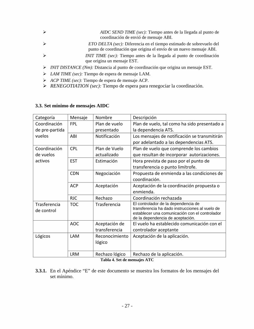
- 27 -
AIDC SEND TIME (sec): Tiempo antes de la llegada al punto de coordinación de envió de mensaje ABI.
ETO DELTA (sec): Diferencia en el tiempo estimado de sobrevuelo del punto de coordinación que origina el envío de un nuevo mensaje ABI.
INIT TIME (sec): Tiempo antes de la llegada al punto de coordinación que origina un mensaje EST.
INIT DISTANCE (Nm): Distancia al punto de coordinación que origina un mensaje EST.
LAM TIME (sec): Tiempo de espera de mensaje LAM.
ACP TIME (sec): Tiempo de espera de mensaje ACP. RENEGOTIATION (sec): Tiempo de espera para renegociar la coordinación.
3.3. Set mínimo de mensajes AIDC
Categoría Mensaje Nombre Descripción
Coordinación de pre‐partida vuelos
FPL Plan de vuelo presentado
Plan de vuelo, tal como ha sido presentado a la dependencia ATS.
ABI Notificación Los mensajes de notificación se transmitirán por adelantado a las dependencias ATS.
Coordinación de vuelos activos
CPL Plan de Vuelo actualizado
Plan de vuelo que comprende los cambios que resultan de incorporar autorizaciones.
EST Estimación Hora prevista de paso por el punto de transferencia o punto limítrofe.
CDN Negociación Propuesta de enmienda a las condiciones de coordinación.
ACP Aceptación Aceptación de la coordinación propuesta o enmienda.
RJC Rechazo Coordinación rechazada
Trasferencia de control
TOC Trasferencia El controlador de la dependencia de transferencia ha dado instrucciones al vuelo de establecer una comunicación con el controlador de la dependencia de aceptación.
AOC Aceptación de transferencia
El vuelo ha establecido comunicación con el controlador aceptante
Lógicos LAM Reconocimiento lógico
Aceptación de la aplicación.
LRM Rechazo lógico Rechazo de la aplicación. Tabla 4. Set de mensajes ATC
3.3.1. En el Apéndice “E” de este documento se muestra los formatos de los mensajes del
set mínimo.

- 28 -
3.4. Procedimientos AIDC
3.4.1. Etapa de notificación 3.4.1.1. El FPL ingresa al sistema y la coordinación está en estado Pre-Notificación (FPL‐SAEZ/SACO‐ARG1502‐IS‐A320/M‐SW/C‐SAEZ1235‐N0450F320 ATOVO3B ATOVO
UW5 CBA‐SACF0055‐EET/SACF0037) Este es un plan de vuelo de un vuelo que se realizará desde el Aeropuerto Internacional de Ezeiza, Buenos Aires, al Aeropuerto Internacional de Córdoba, Córdoba, con su hora propuesta de salida para las 1235 UTC.
3.4.1.2. Un tiempo predeterminado antes de la hora prevista de paso sobre el punto de
coordinación, el sistema envía un ABI. El FPLla coordinación pasa a estado notificado.
(ABI‐ARG1502/A1701‐SAEZ‐UBREL/1330F320‐SACO‐8/IS‐9/A320/M‐10/SW/C)
Este es el mensaje ABI que envía el sistema automatizado de Ezeiza para indicar al sistema automatizado de Córdoba que el ARG1502 estará en la posición UBREL a las 1330.
3.4.1.3. El sistema recibe un LAM confirmando que el sistema del centro contiguo posee
el plan de vuelo. (LAM)
3.4.1.4. Durante la fase de notificación el sistema enviar un mensaje ABI con cada modificación que se realice sobre el FPL, recibiendo un LAM por cada ABI enviado
3.4.2. Etapa de coordinación 3.4.2.1. Un tiempo determinado antes de la hora estimada de paso sobre el punto de
coordinación o a una determinada distancia del mismo, el sistema envía un mensaje de EST y el FPL la coordinación pasa a estado CoordinaciónCoordinando
(EST‐ARG1502/A1701‐SAEZ‐UBREL/1345F320‐SACO)
Este es un mensaje EST que envía el sistema de Ezeiza al sistema de Córdoba informándole que el avión está en vuelo y estima pasar por el punto de coordinación a las 1345.
3.4.2.2. El sistema recibe un LAM confirmando la recepción del mensaje EST. (LAM)
3.4.2.3. El operador del Centro de Control receptor debe aceptar (ACP) o negociar (CDN)
la coordinación y esta pasa a estado Coordinado.

- 29 -
3.4.2.4. Si el operador del Centro de Control receptor acepta la coordinación, el FPL pasa a
estado Coordinado.
(ACP‐ARG1502‐SAEZ‐SACO) 3.4.2.5. El sistema recibe un ACP y envía un LAM. (LAM)
3.4.3. Etapa de negociación 3.4.3.1. Si el operador del Centro de Control receptor renegocia la coordinación (CDN), el
FPL la coordinación pasa a estado Renegociación. (CDN‐ARG1502‐SAEZ‐SACO‐14/UBREL/0450F340)
Este es un mensaje CDN enviado por el operador de Córdoba solicitando que el vuelo ARG1502 sea transferido con FL340.
3.4.3.2. El sistema recibe un CDN y envía un LAM. (LAM)
3.4.3.3. El operador del Centro de Control de origen debe aceptar (ACP) o negociar (CDN)
la coordinación 3.4.3.4. Si el operador del Centro de Control originador acepta la coordinación (ACP), el
FPL la coordinación pasaregresa a estado Coordinado. (ACP‐ARG1502‐SAEZ‐SACO)
3.4.3.5. El sistema envía un ACP y recibe un LAM. (LAM)
3.4.3.6. Si el operador del Centro de Control originador renegocia la coordinación (CDN),
el FPL la coordinación pasa a estado renegociación. (CDN‐ARG1502‐SAEZ‐SACO‐14/UBREL/0450F300)
Este es un mensaje CDN enviado por el operador de Ezeiza solicitando al operador de Córdoba que autorice FL300 para el vuelo ARG1502.
3.4.3.7. El sistema envía un CDN y recibe un LAM.

- 30 -
(LAM)
3.4.4. Etapa de transferencia 3.4.4.1. Cuando la aeronave se encuentre próxima al FIX de coordinación, a una distancia
o en las condiciones establecidas en la carta de acuerdo entre las dependencias, el operador del Centro de Control originador debe enviar un mensaje de Transferencia (TOC). El FPL La coordinación pasa a estado transfiriendo.
(TOC‐ARG1502/A1701‐SAEZ‐SACO)
3.4.4.2. El sistema envía un TOC y recibe un LAM. (LAM)
3.4.4.3. El operador del Centro de Control receptor debe aceptar la trasferencia con un
mensaje de aceptación de transferencia (AOC). El FPLLa coordinación pasa a estado Transferido.
(AOC‐ARG1502/A1701‐SAEZ‐SACO)
3.4.4.4. El sistema recibe un AOC y envía un LAM. (LAM)
3.4.4.5. Pueden realizarse negociaciones después de haber concretado la transferencia de
un vuelo.
3.4.4.6. Nótese que en condiciones normales de coordinación, la tarea del operador del sector donde se origina el vuelo se reduce a observar el estado de coordinación en su tabla de vuelos. Por su parte el operador de la dependencia que recibirá el vuelo solo debe ejercer sobre el sistema la acción de aceptar la coordinación. De esta manera se verá reducida notablemente la carga de trabajo de los operadores/coordinadores como así también los eventuales errores cometidos por mala interpretación, olvidos o descuidos.
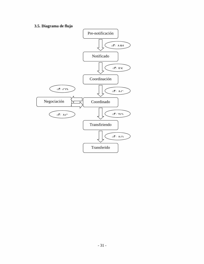
- 31 -
3.5. Diagrama de flujo
Pre-notificación
ABI
Notificado
ES
Coordinación
AC
Coordinado
TO
Transfiriendo
AO
Transferido
Negociación
AC
CD

- 32 -
3.6. Fases para las pruebas de implementación 3.6.1. Primera fase
3.6.1.1. Se debe realizar la configuración de los sistemas automatizados ATC de forma tal
que estos puedan imitar, de la mejor manera posible, los tiempos y distancias que los controladores contemplan para iniciar las coordinaciones con las unidades de control adyacentes.
3.6.1.2. Quién realice las adaptaciones y configuraciones del sistema debe conocer cuáles serán los mailbox destinados a las pruebas (tanto los propios como los de su contraparte).
3.6.1.3. Habrá que tener en cuenta que las pruebas se realizarán de simulador a simulador y debes inhibirse todas las direcciones AFNT/AMHS de las unidades de control que no serán afectadas por las pruebas. Por ejemplo, deben quitarse de las bases de datos las direcciones de los aeródromos a los cuales normalmente se les envían los mensajes de despegue en forma automática.
3.6.2. Segunda fase
3.6.2.1. Se confeccionará un protocolo de pruebas que cubra la más amplia casuística y
ejecutarán las pruebas entre las dos unidades de control con la participación de personal técnico, personal de gestión de base de datos y personal operativo, siguiendo este protocolo.
3.6.2.2. Las pruebas consistirán en generar FPL’s en ambas unidades de control y
comprobar que los sistemas trasmiten en forma automática los mensajes de notificación y coordinación, de acuerdo con los tiempos y distancias establecidas en la configuración.
3.6.2.3. Se recomienda utilizar como ID de la aeronave (casilla 07) el designador AIDC o
TEST, seguido de un número de secuencia en las pruebas. 3.6.2.4. En caso de utilizarse la modalidad CPL para los mensajes de coordinación inicial,
se debe asegurar que este mensaje crea y activa aun FPL en la unidad receptora, si este FPL no existiera antes.
3.6.2.5. También se comprobará el correcto funcionamiento de los mensajes de aceptación,
rechazo y transferencia y se analizarán los motivos por los cuales los sistemas envían y recibes eventuales mensajes LRM.

- 33 -
3.6.3. Tercera fase 3.6.3.1. Cuando haya concluido con éxito la fase anterior y se haya comprobado el
correcto intercambio de mensajería entre los sistemas, se llevarán a cabo las pruebas operativaspre-operacionales, en las que participarán los supervisores, instructores y controladores de cada unidad de control.
3.6.3.2. Para cumplimentar esta etapa, habrá de tenerse en cuenta el adiestramiento del
personal operativo referente a la utilización del AIDC y sus beneficios. 3.6.4. Cuarta fase 3.6.4.1. Una vez que los procedimientos de coordinación AIDC hayan sido probados y
aceptados por el personal operativo, se dará comienzo a las pruebas operacionales y se realizarán las nuevas cartas de acuerdo entre unidades de control, incorporando al AIDC, en primera instancia como medio de coordinación alternativo y posteriormente como medio de coordinación principal.

- 34 -
APÉNDICE A COMPOSICIÓN DE LOS MENSAJES ATS
Campos de los mensajes ATS
Campo
Elemento (a) Elemento (b)
Elemento (c)
Elemento (d) Elemento (e)
03 Designador de tipo de mensaje
Número mensaje
Datos de referencia
07 Identificador de aeronave
Modo SSR Código SSR
09 Número de aeronaves
Tipo de aeronave
Categoría de estela turbulenta
10 Equipo y capacidades de radiocomunicaciones y de ayudas para la navegación y la aproximación
Equipo y capacidades de vigilancia
13 Aeródromo de salida
Hora
14 Punto límite Hora en el punto límite
Nivel autorizado
Datos complementarios
Condiciones
15 Velocidad de crucero
Nivel de crucero
Ruta
16 Aeródromo de destino
Duración total prevista
Aeródromos de alternativa de destino
18 Otros datos
22 Indicador de campo Datos modificados
31 Designador de instalación
Designador de sector
32 Hora Posición Velocidad terrestre de la traza
Rumbo de la traza
Altitud notificada

- 35 -
FPL (plan de vuelo presentado) FPL Campo Elementos
necesarios Elementos opcionales
Comentarios
03 a. b.
07 a. b. c. Código SSR sólo se envía si uno está (ya) asignado y el avión está equipado para ello.
08 a. b. Elemento (b) se incluye según los requisitos del acuerdo de límites.
09 b. c. a.
10 a. b.
13 a. b.
15 a. b. c.
16 a. b. c.
18 a. otra información Elemento (a) se incluye sólo si no se incluye ninguna otra información. Cualquier elemento (a) u otra información (pero no ambos) deben ser incluidos.
ABI (mensaje de notificación) ABI Campo Elementos
necesarios Elementos opcionales
Comentarios
03 a. Elemento (c) deberá contener el número de referencia del primer mensaje enviado para este vuelo.
07 a. b. c. Si un código SSR ha sido asignado debe ser incluido.
13 a.
14 a. b. c. d. e.
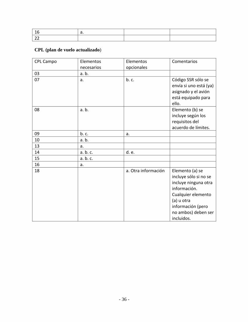
- 36 -
16 a.
22 CPL (plan de vuelo actualizado) CPL Campo Elementos
necesarios Elementos opcionales
Comentarios
03 a. b.
07 a. b. c. Código SSR sólo se envía si uno está (ya) asignado y el avión está equipado para ello.
08 a. b. Elemento (b) se incluye según los requisitos del acuerdo de límites.
09 b. c. a.
10 a. b.
13 a.
14 a. b. c. d. e.
15 a. b. c.
16 a.
18 a. Otra información Elemento (a) se incluye sólo si no se incluye ninguna otra información. Cualquier elemento (a) u otra información (pero no ambos) deben ser incluidos.

- 37 -
EST (estimaciones) EST Campo Elementos
necesarios Elementos opcionales
Comentarios
03 a. b. c. Elemento (c) deberá contener el número de referencia del último mensaje enviado para este vuelo.
07 a. b. c. Código SSR sólo se envía si uno está asignado y el avión está equipado para ello.
13 a. Aeródromo de salida debe coincidir con el valor previamente enviado en el FPL o el último CHG que modificó la FPL.
14 a. b. c. d. e.
16 a. Aeródromo de destino debe coincidir con el valor previamente enviado en el FPL o el último CHG que modificó la FPL.
CDN (mensaje de negociación) CDN Campo Elementos
necesarios Elementos opcionales
Comentarios
03 a. b. c.
07 a. b. c.
13 a. b.
14 a. b. c. d.
16 a.

- 38 -
ACP (mensaje de aceptación) ACP Campo Elementos
necesarios Elementos opcionales
Comentarios
03 a. b. c.
07 a. b. c.
13 a. b.
16 a. RJC (mensaje de rechazo) RJC Campo Elementos
necesarios Elementos opcionales
Comentarios
03 a. b. c.
07 a. b. c.
13 a. b.
16 a. TOC (mensaje de trasferencia) TOC Campo Elementos
necesarios Elementos opcionales
Comentarios
03 a. b. c.
07 a. b. c.
13 a. b.
16 a. AOC (asumida la transferencia) AOC Campo Elementos
necesarios Elementos opcionales
Comentarios
03 a. b. c.
07 a. b. c.
13 a. b.
16 a.

- 39 -
LAM (acuse de recibo lógico) LAM Campo Elementos
necesarios Elementos opcionales
Comentarios
03 a. b. c. LRM (rechazo lógico) LRM Campo Elementos
necesarios Elementos opcionales
Comentarios
03 a. b. c.
18 texto como se muestra en Comentarios
Describe el código de error: después de RMK /, incluye dos dígitos que comprenden el código de error.

- 40 -
LISTA DE ACRONIMOS ABI Advance Boundary Information (AIDC message) ACC Area Control Centre ACP Acceptance (AIDC message) ADS Surveillance ADS-C (AIDC message) ADS-B Automatic Dependent Surveillance - Broadcast ADS-C Automatic Dependent Surveillance - Contract AFTN Aeronautical Fixed Telecommunications Network AFTN Aeronautical Fixed Telecommunications Network AIDC ATS Interfacility Data Communications AMHS Aeronautical Message Handling System AMHS ATS Message Handling System AOC Airline Operational Control; or Assumption of Control (AIDC message) APP Approach Control Office ASCII American Standard Code for Information Interchange ASIA/PAC Asia/Pacific ATC Air Traffic Control ATM Air Traffic Management ATN Aeronautical Telecommunications Network ATN Aeronautical Telecommunication Network ATS Air Traffic Service ATS Air Traffic Services ATSU Air Traffic Service Unit CAAS Common AMHS Addressing Scheme CARSAM Caribe - Sudamérica CCAM Centro de Conmutación Automática de Mensajes CDN Coordination (AIDC message) CH AFTN Channel CHG ICAO Modification Message CNS Communications, Navigation, Surveillance CPDLC Controller Pilot Data Link Communications CPL Current Flight Plan (AIDC message) DS Servidor de directorio que se comunica siguiendo protocolos X.500 DS Directory Service EST Coordination Estimate (AIDC message) FPL Filed Flight Plan IA-5 International Alphabet 5 ICAO International Civil Aviation Organization ICD Interface Control Document IP Internet Protocol IPM Inter Personal Message IPv4 Internet Protocol version 4 IPv4 REDDIG SAM: Refiere al plan de direccionamiento ip, versión 4. Utiliza la REDDIG y
corresponde a la región SAM ITA-2 International Telegraph Alphabet No. 2 LAM Logical Acknowledgement Message (AIDC message) LAN REDDIG: entorno asociado al plan de direcciones ip regional para cada Estado LRM Logical Rejection Message (AIDC message)

- 41 -
MS Almacén de mensajes para manejar la entrega y recuperación de mensajes.
MTA Agente encargado de encaminar los mensajes entre MTAs, MSs y MTA Message Transfer Agent MTCU Message Transfer and Conversion Unit NAT Network Address Translation NAT: protocolo de traslación de direcciones ip. Oral ATS Circuito de Voz para comunicaciones ATS OSI Open System Inter-connection P1 Protocolo para comunicar y encaminar mensajes entre MTAs
(ITU-T X.411) P3 Protocolo de entrega (“fronteras adentro”, tipo “pull”) P7 Protocolo para que el UA retire del MS (ITU-T X.413).(tipo
“push”) REDDIG Red Digital Sudamericana REJ Rejection (AIDC message) TCP Transfer of Control Point TOC Transfer of Control (AIDC message) TWR Torre de Control de Aeródromo UA Agentes de usuario UA User Agent UTC Universal Coordinated Time WAN REDDIG: Entorno asociado al plan de direcciones ip regional para interconexión
entre Estados

Pan Regional (NAT
and APAC) Interface
Control Document for
ATS Interfacility Data
Communications
(PAN AIDC ICD)
This edition has been issued by the Inter-Regional AIDC Task Force for the Asia/Pacific Air Navigation Planning and Implementation Regional Group (APANPIRG) and the North Atlantic Systems Planning Group (NAT SPG).
Version 1.0 — September 2014
International Civil Aviation Organization
APÉNDICE C AIDC/1-NE/02

Version 1.0 – September 2014 ii PAN ICD
This document is available by accessing any of the following ICAO regional websites.
Asia and Pacific (APAC) Office http://www.icao.int/apac
European and North Atlantic (EUR/NAT) Office http://www.paris.icao.int
For more information, contact the ICAO regional office.

PAN ICD iii Version 1.0 – September 2014
Pan Regional (NAT
and APAC) Interface
Control Document for
ATS Interfacility Data
Communications
(PAN AIDC ICD)
This edition has been issued by the Inter-Regional AIDC Task Force for the Asia/Pacific Air Navigation Planning and Implementation Regional Group (APANPIRG) and the North Atlantic Systems Planning Group (NAT SPG).
Version 1.0 — September 2014
International Civil Aviation Organization

Version 1.0 – September 2014 iv PAN ICD
Amendments to the PAN ICD
The following table will be used to track updates to the PAN ICD by the Ad Hoc Working Group. This document contains procedures material from the Asia/Pacific Regional ICD for AIDC and the North Atlantic Common Coordination ICD.
Amendment Source Subject(s) Date
0.1 Not used
0.2 Pre-PAN ICD Annotated outline incorporated into document structure May 2010
0.3 PAN ICD The draft document at this stage is focused on populating the outline with relevant material. Document style, formatting, and presentation of material are still to be considered.
October 2010
0.4 PAN ICD Comments inserted from v0.3 comment forms
Changes inserted from NAT CC ICD new v1.2.9 to reflect editorial changes and corrections
Changes inserted from NAT CC ICD new v1.3.0 to reflect changes specified in Amendment 1, effective 15 Nov 2012, to the ICAO Doc 4444 Procedures for Air Navigation Services-Air Traffic Management, Fifteenth Edition
November 2011
0.5 PAN ICD (IRAIDTF/1) updated Version 0.4 of the PAN Regional ICD for AIDC to include comments from Iceland, Australia, the APAC AIDC Seminar, and the Secretariat.
January 2013
0.6 PAN ICD (IRAIDTF Web/1) added AIDC+LRM response examples, AIDC message table, proposed field 15 wording, sample AIDC message containing field 15, Field 14-Estimate Data added and moved to Chapter 4.
February 2013
0.7 PAN ICD (IRAIDTF Web/2) Chapter 8 will be deleted and included in a new appendix; added LRM examples, new AIDC message table, new Field 15 wording.
April 2013
0.8 PAN ICD IRAIDTF/2 updated Version 0.7 of the Pan Regional ICD for AIDC and removed Chapter 8, Chapter 9 relocated as Attachment A and Chapter 6 relocated as Attachment B to the ICD.
July 2013
0.85 PAN ICD IRAIDTF/3 updated Version 0.83 in Chapters 3, 4, 5 and 6. Renumbering Appendices A,B and C
March 2014

PAN ICD v Version 1.0 – September 2014
0.86 PAN ICD Subsequent to Web/3 held on 11 June 2014, IRAIDTF updated Version 0.85 in Chapters 2, 4 and 6. Additional Implementation Guidance Material appended as Appendix C
June 2014
0.91 PAN ICD Subsequent to Web/4 held on 9 July 2014, IRAIDTF updated Version 0.86 in Chapters 2, 3, 4 and 6.
July 2014
0.92 PAN ICD Subsequent to Web/5 held on 6 August 2014, IRAIDTF updated Version 0.91 in Chapters 2, 3, 4 and 6 mainly related to Restriction Formats and Field 15.
August 2014
1.0 PAN ICD A few editorial corrections to Version 0.92 September 2014

Version 1.0 – September 2014 vi PAN ICD
AMENDMENTS
The issue of amendments is announced by the ICAO Regional Offices concerned, which holders of this publication should consult. The space below is provided to keep a record of such amendments.
RECORD OF AMENDMENTS AND CORRIGENDA
AMENDMENTS CORRIGENDA
No. Date applicable
Date entered
Entered by No. Date applicable
Date entered
Entered by

Version 1.0 – September 2014 vii PAN ICD
Table of Contents
Page
FOREWORD ............................................................................................................................................ ix
1. Historical background .......................................................................................................... ix
2. Scope and Purpose ............................................................................................................... ix
3. Status ...................................................................................................................................... x
4. Implementation ...................................................................................................................... x
5. References .............................................................................................................................. x
6. Changes to the document ....................................................................................................... x
Chapter 1 Abbreviations and AIDC Messages ................................................................................... 1-1
1.1 Abbreviations ........................................................................................................................ 1-1 1.2 AIDC Messages .................................................................................................................... 1-5
Chapter 2 Purpose, Policy and Units of Measurement ....................................................................... 2-1
2.1 Purpose ................................................................................................................................. 2-1 2.2 Policy .................................................................................................................................... 2-1 2.3 Units of measurement and data convention .......................................................................... 2-2 2.4 Restriction Formats ............................................................................................................... 2-4
Chapter 3 Communications and Support Mechanisms ....................................................................... 3-1
3.1 Introduction .......................................................................................................................... 3-1 3.2 Message Headers, Timers and ATSU Indicators .................................................................. 3-1 3.3 Engineering considerations ................................................................................................... 3-4 3.4 Test considerations ............................................................................................................... 3-6 3.5 Scheduled Maintenance and Failures ................................................................................... 3-7
Chapter 4 AIDC Messages ................................................................................................................. 4-1
4.1 Introduction .......................................................................................................................... 4-1 4.2 Message Field Requirements ................................................................................................ 4-1 4.3 AIDC message groups ........................................................................................................ 4-10 4.4 Notification messages ......................................................................................................... 4-11 4.5 Coordination messages ....................................................................................................... 4-12 4.6 Transfer of control messages .............................................................................................. 4-24 4.7 General information messages ............................................................................................ 4-25 4.8 Application management messages .................................................................................... 4-26 4.9 Surveillance Data Transfer Service Messages .................................................................... 4-34
Chapter 5 Error Codes ........................................................................................................................ 5-1
5.1 Introduction .......................................................................................................................... 5-1
Chapter 6 Implementation Guidance Material.................................................................................... 6-1
6.1 Introduction .......................................................................................................................... 6-1 6.2 Preliminaries ......................................................................................................................... 6-1 6.3 AIDC message sequences and AIDC flight states .............................................................. 6-11 6.4 Message Sequencing ........................................................................................................... 6-28

PAN ICD
Version 1.0 – September 2014 viii PAN ICD
6.5 Other AIDC messages ........................................................................................................ 6-32 6.6 Examples ............................................................................................................................ 6-42
Tables
Table 4-1. Contents of Field 14 ........................................................................................................... 4-1
Table 4-2. Contents of Field 15 ........................................................................................................... 4-6
Table 4-3. AIDC Messages ................................................................................................................ 4-10
Table 4-4. CPDLC Connection Status ............................................................................................... 4-33
Table 4-5. Frequency Identifier ......................................................................................................... 4-33
Table 4-6. PAN AIDC Messages and their Field Composition ......................................................... 4-36
Table 5-1. Error Codes ......................................................................................................................... 5-1
Table 6-1. Required Operational Response ......................................................................................... 6-3
Table 6-2. AIDC Flight States ........................................................................................................... 6-11
Table 6-3. Flight State Transition table ............................................................................................. 6-23
Table 6-4. AIDC Message Sequence of commonly used AIDC messages ........................................ 6-28
Table 6-5. Valid Messages by ATSU and flight states ...................................................................... 6-30
Table 6-6. FCN Transmission ............................................................................................................ 6-35
List of Figures
Figure 6-1 Flight State Transition Diagram ....................................................................................... 6-27
Figure 6-2. Routine Data Link Transfer Using FAN and FCN Messaging......................................... 6-36
Figure 6-3 CPDLC Transfer Using FAN and FCN Messaging – Initial Connection Request Failed 6-37
Figure 6-4 CPDLC Transfer Using FAN and FCN Messaging – Unable to Establish CPDLC Connection ........................................................................................................................ 6-38
Figure 6-5 CPDLC Transfer Using FAN and FCN Messaging – Initial NDA not Delivered ........... 6-39
Appendices
Appendix A Templates for Bilateral Letter of Agreement on AIDC
Appendix B Regionally Specific Messages
Appendix C Additional Implementation Guidance Material

PAN ICD ix Version 1.0 – September 2014
FOREWORD
1. Historical background
1.1 The Pan Regional Interface Control Document (PAN ICD) for ATS Interfacility Data Communications (AIDC) is the result of the progressive evolution of the Asia/Pacific Regional ICD for AIDC, issued by the ICAO Asia/Pacific Regional Office on behalf of the Asia Pacific Air Navigation Planning and Implementation Regional Group (APANPIRG), and the North Atlantic Common Coordination ICD, published by the ICAO European and North Atlantic Office, on behalf of the North Atlantic Systems Planning Group (NAT SPG).
1.2 Each of the two founding documents provided guidance on a regional basis. However, in recognition of the need to provide globally harmonized guidance for AIDC, the PAN ICD First Edition, merging the APAC and NAT guidance material, was adopted by the APAC and NAT Regions in 2014.
1.3 The PAN ICD addresses the ground-ground data link provision from a technical and operational point of view taking into account lessons learned, global implications and guidance on recent initiatives.
2. Scope and Purpose
2.1 The PAN-ICD provides guidance and information concerning ground-ground data link operations and is intended to facilitate the uniform application of Standards and Recommended Practices contained in Annex 2 — Rules of the Air, Annex 10 — Aeronautical Telecommunications and Annex 11 — Air Traffic Services, the provisions in the Procedures for Air Navigation Services — Air Traffic Management (PANS-ATM, Doc 4444) and, when necessary, the Regional Supplementary Procedures (Doc 7030).
2.2 This guidance material specifies the facilities and messages to be used for the exchange of notification, coordination, transfer of control, and related data between automated Air Traffic Service (ATS) systems. The material is intended to improve safety and maximize operational benefits by promoting standardized ground-ground data link operations throughout the world.
2.3 The following personnel and organizations should be familiar with relevant aspects of its contents: regulators, airspace planners, air navigation service providers (ANSPs), training organizations, regional/State monitoring agencies, automation specialists at centers and equipment suppliers.
2.4 The guidance will support the following activities:
a) Safety regulatory oversight of air navigation services;
b) The development of letters of agreements between ANSPs;
c) The development of operational procedures;
d) The implementation activities; and,
e) Operational monitoring, analysis, and exchange of operational data among regions and States.
2.5 The messages defined in this document are used during the various stages of the flight. Though outside the scope of the AIDC application, the Emergency-, Flight Planning- and Supplementary Message Categories as defined in PANS-ATM Appendix 3 will continue to be used to perform functions not provided by the AIDC application.
2.6 In particular, the Flight Planning function is required and will be required in the future to support operations. The ICAO messages FPL (Filed Flight Plan), CHG (Modification), DLA (Delay),

PAN ICD
Version 1.0 – September 2014 x PAN ICD
DEP (Departure), ARR (Arrival), CNL (Cancel) and RQP (Request Flight Plan) will be used to support this function.
2.7 There is a great need for a communications and data interchange infrastructure to significantly reduce the need for verbal coordination between ATSUs. AIDC standards, as defined in the PAN ICD, provide a harmonized means for data interchange between ATS units during the notification, coordination, confirmation and transfer of control phases of operations.
2.8 The message sets and procedures described in the PAN ICD have been designed for use with the ATS Message Handling System (AMHS) and/or Aeronautical Fixed Telecommunications Network (AFTN). They can also be exchanged over dedicated private communication lines. In the interest of global standardization, ICAO methods and messages as defined in PANS-ATM Appendix 3 Air Traffic Services Messages were used wherever possible. Where ICAO methods and messages do not meet requirements, new messages were identified using existing ICAO field definitions to the extent possible. Specifically, the PAN ICD defines the following:
a) Basic communications and support required to coordinate implementation of AIDC;
b) Common boundary agreements between all the ATSUs concerned;
c) Implementation guidance material;
3. Status
3.1 This guidance is approved and maintained by the respective participating PIRGs and has a status of an ICAO regional guidance material. It contains material that may eventually become Standards and Recommended Practices (SARPs) or PANS provisions when it has reached the maturity and stability necessary for adoption or approval. It also comprises material prepared as an amplification of the basic principles in the corresponding SARPs, and designed particularly to assist the user in the application of the SARPs and PANS.
4. Implementation
4.1 With a view of facilitating implementation of the provisions herein by States, this guidance material has been prepared using language that permits direct use by all users.
5. References
5.1 The following references are cited in this document:
a) Annex 2 — Rules of the Air,
b) Annex 10 — Aeronautical Telecommunications,
c) Annex 11 — Air Traffic Services,
d) PANS - Air Traffic Management (Doc 4444),
e) PANS - Regional Supplementary Procedures (Doc 7030),
f) PANS – ICAO Abbreviations and Codes (Doc 8400).
6. Changes to the document
6.1 This document is maintained as a regional document in coordination with all ICAO planning and implementation regional groups (PIRGs) providing ground-ground data link services within their

PAN ICD
PAN ICD xi Version 1.0 – September 2014
region. Each participating PIRG establishes a mechanism for submitting and administering change proposals.
6.2 Change proposals (CPs) can be submitted by any stakeholder participating in ground-ground data link operations. The stakeholder should submit a Change Proposal to their ICAO regional office. The ICAO regional office will coordinate the change proposal within its own region, other regions, and ICAO HQ, to determine the acceptability of the change proposal. Once the ICAO regional office has completed coordination and the participating PIRGs accept the change proposal, the document is updated.

PAN ICD
Version 1.0 – September 2014 xii PAN ICD
Amendments to the PAN ICD
Amendment Source(s) Subject(s) Approved applicable
1st Edition ([date])
Asia/Pacific Air Navigation Planning and Implementation Regional Group (APANPIRG/ – [year])
North Atlantic Systems Planning Group (NAT SPG/ – [year])
Pan Regional ICD (PAN ICD) Applicable within participating Regions on [date].

PAN ICD
PAN ICD 1-1 Version 1.0 – September 2014
Chapter 1 Abbreviations and AIDC Messages 1.1 Abbreviations
1.1.1 When the following abbreviations are used in the present document they have the following meanings. Where the abbreviation has “(ICAO)” annotated, the term has already been decoded in ICAO DOC 8400 (PANS-ICAO Abbreviations and Codes, Eighth Edition-2010).
Abbreviations
ACARS Aircraft Communication Addressing and Reporting System (ICAO)
ACI Area of Common Interest
ACID Aircraft Identification
ADF Application Data Field (FAN Message)
ADF ADS-C Data Field (ADS Message)
ADS-B Automatic Dependent Surveillance - Broadcast (ICAO)
ADS-C Automatic Dependent Surveillance – Contract (ICAO)
AFD Standard Message Identifier (SMI) for ATS Facility Notification (ARINC622)
AFN ATS Facilities Notification
AFTN Aeronautical Fixed Telecommunication Network (ICAO)
AIDC ATS Interfacility Data Communications (ICAO)
AMHS ATS Message Handling System
ANSPs Air Navigation Service Providers
APAC Asia and Pacific Office
APANPIRG Asia/Pacific Air Navigation Planning and Implementation Regional Group
ARINC Aeronautical Radio Inc.
ARR Arrival (ICAO)
ATC Air Traffic Control (ICAO)
ATM Air Traffic Management (ICAO)
ATMOC Air Traffic Management Operations Centre
ATS Air Traffic Services (ICAO)
ATSC Air Traffic Service Center (ICAO)
ATSU Air Traffic Service Unit
ATSU-1 Transferring/Upstream ATSU
ATSU-2 Receiving/Downstream ATSU
CFL Cleared Flight Level

PAN ICD
Version 1.0 – September 2014 1-2 PAN ICD
CHG Modification Message (ICAO)
CNL Cancel (ICAO)
COP Change Over Point (ICAO)
CPD CPDLC Connection Status identifier
CPDLC Controller Pilot Data Link Communications (ICAO)
CPs Change proposals
CRC Cyclic Redundancy Check (ICAO)
CSF Communication Status Field
DCT Direct (ICAO)
DEP Departure (ICAO)
DEST Destination (ICAO)
DIA Coordination Dialogue
DLA Delay (ICAO)
DOF Date of Flight
EOBT Estimated Off Block Time (ICAO)
FANS Future Air Navigation System
FI Flight Identifier
FIR Flight Information Region (ICAO)
FM3 Standard Message Identifier (SMI) for the Center (#3) Flight Management Computer (ARINC622)
FMC Flight Management Computer (ICAO)
FMD Flight Management Computer (Selected)
FMH Facilities Notification Message Header
FML Flight Management Computer (Left)
FMR Flight Management Computer (Right)
FN_CAD AFN Contact Advisory
FPL Filed Flight Plan (ICAO)
FPO Facilities Notification Current Position
FREQ Frequency (ICAO)
GOLD Global Operational Data Link Document
HDG Heading (ICAO)
HQ Head Quarter

PAN ICD
PAN ICD 1-3 Version 1.0 – September 2014
IA-5 International Alphabet
ICAO International Civil Aviation Organization
ICD Interface Control Document
IMI Imbedded Message Identifier
IRAIDTF Inter-Regional AIDC Task Force
LOA Letter of Agreement
MAS Message Assurance
MOU Memorandum of Understanding
MTI Message Type Identifier
NAT CC ICD North Atlantic Common Coordination ICD.
NAT SPG North Atlantic Systems Planning Group
NDA Next Data Authority
OAC Oceanic Area Control Centre (ICAO)
OCA Oceanic Control Area (ICAO)
OCS Oceanic Control System
ODF Optional Data Field
OTD Off track deviation
PAN ICD Pan Regional Interface Control Document
PANS Procedures for Air Navigation Services (ICAO)
PANS-ATM Procedures for Air Navigation Services – Air Traffic Management
PIRGs Planning and Implementation Regional Groups
PRL Present Level
RFL Requested Flight Level
RMK Remark (ICAO)
RNP Required Navigational Performance (ICAO)
RQP Request Flight Plan (ICAO)
SARPs Standards and Recommended Practices (ICAO)
SMI Standard Message Identifier
SOH Start of Header
SPD Speed
STX Start of Text
T Truncation indicator

PAN ICD
Version 1.0 – September 2014 1-4 PAN ICD
TDF Track Data Field
UTC Coordinated Universal Time (ICAO)
VSP Variable System Parameter

PAN ICD
PAN ICD 1-5 Version 1.0 – September 2014
1.2 AIDC Messages
1.2.1 Where the AIDC Message has “(ICAO)” annotated, the term has already been decoded in ICAO DOC 8400 (PANS-ICAO Abbreviations and Codes, Eighth Edition-2010). AIDC message abbreviations marked with “*” may have different formats from ICAO ATS Messages.
AIDC Messages with some of its fields and elements
ABI * Advance Boundary Information (ICAO)
ACP * Acceptance (ICAO)
ADS Surveillance ADS-C
AOC Acceptance of Control
ASM Application Status Monitor
CDN * Coordination Negotiation [CDN: Coordination (ICAO)]
CPL * Current Flight Plan (ICAO)
EMG Emergency
EST * Coordination Estimate [EST: Estimate (ICAO)]
FAN FANS Application Message
FCN FANS Completion Notification
FCO Facilities Notification Contact
LAM * Logical Acknowledgement Message (ICAO)
LRM Logical Rejection Message
MAC Cancellation of Notification and/or Coordination
MIS Miscellaneous
NAT NAT Organized Tracks message; or North Atlantic (ICAO)
PAC Preliminary Activate
PCA Profile Confirmation Acceptance
PCM Profile Confirmation Message
REJ Rejection
TDM Track Definition Message
TOC Transfer of Control
TRU Track Update


PAN ICD
PAN ICD 2-1 Version 1.0 – September 2014
Chapter 2 Purpose, Policy and Units of Measurement
2.1 Purpose
2.1.1 The AIDC application supports information exchanges between ATC application processes within automated ATS systems located at different ATSUs, as defined in PANS-ATM, Appendix 6. This application supports the Notification, Coordination, Transfer of Control, and Transfer of Data link Communication functions between these ATSUs
2.1.2 The PAN ICD specifies the facilities and messages to be used for the exchange of notification, coordination, confirmation, transfer of control, and transfer of Data link communication related data between automated ATS systems. The messages defined in this document are used during the active phase of flight.
2.2 Policy
2.2.1 The application of AIDC to replace or supplement traditional voice coordination between ATS Units should be based on a step-by-step data distribution scheme comprising three (3) operational phases: NOTIFICATION, COORDINATION, and TRANSFER OF CONTROL. In support of these operational phases, application management messages are required to support application level dialogues between automated ATS systems.
2.2.2 The Advance Boundary Information (ABI) message should be used for notification, subject to bilateral agreement. The ABI can also be used to update the cleared profile of an aircraft, particularly when using abbreviated coordination and not utilizing the CPL message.
2.2.3 For the coordination phase, the Current Flight Plan (CPL) message should be used to coordinate the initial cleared profile in conjunction with the Coordination (CDN) message to negotiate changes. Coordination dialogues must be terminated using an Acceptance (ACP) or a Rejection (REJ) message. If abbreviated coordination is in use, the EST or PAC message should be used for coordination.
2.2.4 Towards the end of the coordination phase, the Profile Confirmation Message (PCM) should be used to confirm that the coordinated information is correct prior to the aircraft crossing the control area boundary. The ATSU receiving the PCM transmits a Profile Confirmation Acceptance (PCA) message to confirm that information in the PCM is in compliance with the previously coordinated information.
2.2.5 The Transfer of Control (TOC) and Acceptance of Control (AOC) messages should be used for the automatic transfer of control function.
2.2.6 In addition to the above, additional AIDC messages are provided, supporting the transfer of FANS-1/A logon information and confirmation of CPDLC connection status from one ATSU to another.
2.2.7 The capability to revert to verbal coordination, manual transfer of control and manual data link transfers (i.e. Address forwarding) should be retained.
2.2.8 Flight plans and flight plan related messages should continue to be filed in accordance with existing procedures.

PAN ICD
Version 1.0 – September 2014 2-2 PAN ICD
2.3 Units of measurement and data convention
2.3.1 AIDC messages described in the PAN ICD may support different units of measurement to those described below. If this occurs, bilateral agreements should determine the units to be transmitted, as well as their format and any associated limitations (e.g. minimum/maximum value, resolution etc.).
2.3.2 Time and Date.
2.3.2.1 All time information should be expressed in UTC as four digits (HHMM) rounded to the nearest whole minute, with midnight expressed as 0000. Subject to bilateral agreement, time may be expressed as 6 digits (HHMMSS). When date information is used, it should be expressed in YYMMDD format
2.3.3 Geographic Position Information.
2.3.3.1 Geographic position information should be specified in accordance with PANS-ATM, Appendix 3.
2.3.4 Level Information.
2.3.4.1 All level information should be specified as flight level(s) or altitude(s) expressed in hundreds of feet. With the exception of block levels and cruise climb, level information – including supplementary crossing data and crossing conditions – should be specified in accordance with PANS-ATM, Appendix 3.
2.3.5 Block Level Information
2.3.5.1 Where a block level is to be included in an AIDC message, it should be expressed as the lower level followed by the upper level.
Example
Format Explanation
F320F340 The aircraft is operating in a block of levels between F320 and F340 (inclusive)
Block level information may be included in Field 14 of any AIDC message, or in the Track Data field of a TRU message.
2.3.6 Cruise Climb Information
2.3.6.1 Where a cruise climb is to be included in an AIDC message, it should be expressed as the upper level followed by lower level, then the single letter C.
Example
Format Explanation
F340F320C The aircraft is cruise climbing from F320 to F340
Cruise climb information may be included in Field 14 of any AIDC message, or in the Track Data field of a TRU message.

PAN ICD
PAN ICD 2-3 Version 1.0 – September 2014
2.3.7 Speed Information
2.3.7.1 All speed information should be expressed as true airspeed in knots or as a true Mach Number. With the exception of Mach Number in Field 14, speed information should be specified in accordance with PANS-ATM, Appendix 3.
2.3.8 Mach Number Information
2.3.8.1 Where Mach Number information is to be included in Field 14 in an AIDC message it should be expressed as:
A single character describing whether an aircraft will be maintaining the notified Mach Number or less (L), the notified Mach Number or greater (G), or exactly the notified Mach Number (E); and
Four characters defining the specified Mach Number, expressed as the letter M followed by 3 figures specifying the Mach Number to the nearest hundredth of unit Mach.
Examples
Format Explanation
GM085 The aircraft is maintaining M0.85 or greater
EM076 The aircraft is maintaining M0.76
LM083 The aircraft is maintaining M0.83 or less
Mach Number information may be included in Field 14 of any AIDC message
2.3.9 Offset and Weather Deviation Information
2.3.9.1 Where Offset or weather deviation information is to be included in an AIDC message it should be expressed as:
A single character describing whether the information is associated with an offset (O) or a weather deviation (W); and,
One to three characters indicating the lateral distance off route associated with this clearance (leading zeros should not be used); and,
A direction, indicating left (L), right (R) or either side of route (E).
Examples
Format Explanation
O30R The aircraft is offsetting 30NM to the right of route
W25E The aircraft is conducting a weather deviation up to 25NM either side of route
W100L The aircraft is conducting a weather deviation up to 100NM to the left of route

PAN ICD
Version 1.0 – September 2014 2-4 PAN ICD
2.3.9.2 Offset and weather deviation information may be included in Field 14 of any AIDC message, or in the Track Data field of a TRU message.
2.3.9.3 When transmitting an AIDC message containing Offset information, the direction “E” (either side of route) should not be used.
2.3.9.4 Valid "off track" distance values are integers between 1 and 250, with no leading zeros. The distance off route is measured in nautical miles (NM).
Note: Refer to Chapter 4 for more information concerning the use of Fields 14 and 15
2.3.10 Functional Addresses.
2.3.10.1 A functional address, which refers to a function within an ATS unit (e.g. an ATC watch supervisor), may be substituted in the MIS and EMG messages for the aircraft identification found in Field 7. Where such an address is used, it is preceded by an oblique stroke “/” to differentiate it from aircraft identification.
2.4 Restriction Formats
2.4.1 Principles.
2.4.1.1 “Restriction” is the term used to describe a clearance that requires an aircraft to comply with an instruction either at, prior to, or after a specific time or position. This instruction may involve a speed, level or speed/level change, or a required time to cross a position.
2.4.1.2 The use of restrictions is optional. This section describes the conventions and formats used to permit the inclusion of a restriction in Field 15 of an AIDC Message transmitted from one ATSU to another.
2.4.1.3 The use of restrictions should be prescribed by bilateral agreement. ATS Units may agree to use all types of restrictions described below, or only a sub-set of them.
2.4.1.4 Restrictions may only be included in Field 15 of AIDC messages.
2.4.1.5 The Field 15 formats described in this section DO NOT support:
the inclusion of a restriction containing a block level or a cruise climb;
the inclusion of a crossing condition as defined for Field 14 (e.g. F350F330A). Where Field 15 contains a restriction containing a change of level, climb or descent to that level is implied;
a restriction involving only a speed change, where that speed change is to be completed at or before a time or position.
2.4.1.6 The Field 15 formats described in this section DO support the coordination of:
level changes, speed changes or speed/level changes that are commencing at or after a time or position;
level changes or speed/level changes that are to be completed at or before a time or position;
requirements to cross a position AT, AT OR BEFORE, or AT OR AFTER a specified time.

PAN ICD
PAN ICD 2-5 Version 1.0 – September 2014
2.4.1.7 The restriction information provided by ATSU 1 to ATSU 2 should be limited to the flight profile at and beyond the ACI boundary associated with ATSU 2. Restrictions prior to the ACI boundary should not be included in AIDC messages transmitted to ATSU 2.
2.4.1.8 The cleared level, supplementary crossing data and crossing conditions in field 14 should be based on the conditions at the point of coordination in Field 14a.
2.4.1.9 If a position that is not in Field 15 of the original flight plan is used in a restriction associated with a speed/level change, this position must be included in Field 15 of the AIDC message.
2.4.2 Terminology.
2.4.2.1 For the purpose of this section of the document, the following terminology applies.
Terminology Refers to…
level change Refers to a clearance solely relating to the cleared level of the aircraft
speed change Refers to a clearance solely relating to the cleared speed of the aircraft
speed/level change Refers to a clearance relating to the cleared speed and level of the aircraft
speed and/or level change Refers to a clearance relating to either a speed change, a level change, or a speed/level change (as described above)
level or speed/level change Refers to a clearance relating to either a level change, or a speed/level change (as described above). It specifically excludes clearances relating solely to a speed change

PAN ICD
Version 1.0 – September 2014 2-6 PAN ICD
2.4.3 Level and/or Speed Restrictions associated with a position.
2.4.3.1 Route, speed and level information contained in Field 14 and Field 15 represent the current cleared (or proposed) profile of the aircraft. The following section describes the required format of a restriction involving a speed and/or level change associated with a position in an AIDC message.
Where a clearance issued to an aircraft requires a speed and/or level change to be commenced after passing a position, then the format of [position] followed by an oblique stroke “/” and the new speed and/or level will be used;
Where a clearance issued to an aircraft requires a level or speed/level change to be completed prior to passing a position then the format of the new level or speed/level followed by an oblique stroke “/” and the [position] will be used;
Where a clearance issued to an aircraft requires a level and/or speed/level change to be commenced after passing a position and to be completed prior to passing the subsequent position then a combination of the two formats described above shall be used.
Intent/Format
i. After passing the specified position, the aircraft is cleared to maintain the specified speed and/or level:
a. [position]/[level] b. [position]/[speed] c. [position]/[speed][level]
Examples
a. MICKY/F350 b. 10N150W/M084 c. 2030N05045W/M084F350
ii. The aircraft is cleared to maintain the specified level or speed/level and to be maintaining the level or speed/level before the specified position:
a. [level]/[position] b. [speed][level]/[position]
Examples
a. F350/2030S15030E b. M084F350/36S163E
iii. After passing the first specified position, the aircraft is cleared to maintain the specified level or
speed/level and to be maintaining the level or speed/level before the second specified position:
a. [position1]/[level]/[position2] b. [position1]/[speed][level]/[position2]
Examples
a. MICKY/F370/30S160E b. 1020N14040W/M084F350/DAFFY

PAN ICD
PAN ICD 2-7 Version 1.0 – September 2014
2.4.3.2 The intent is that the elements in Field 15 remain in chronological order. If the clearance issued to an aircraft requires a level or speed/level change to be commenced after passing one position and to be completed prior to passing a subsequent position (that is not the next position), then the format shown in the example below shall be used:
Intent/Format
After passing the first specified position, the aircraft is cleared to maintain the specified level or speed/level and to be maintaining the level or speed/level before a subsequent position that is not the next position:
a. [position1]/[level] [position2] [position3] [level]/[position4] b. [position1]/[speed][level] [position2] [position3] [speed][level]/[position4]
Examples
a. MICKY/F390 MINNY 05S080E F390/PLUTO b. 1020N14040W/M084F350 DAISY DONLD M084F350/DAFFY
Note. Other valid Field 15 information (e.g. an ATS route designator or DCT) may be included between the two restrictions:
MICKY/M084F350 A123 DONLD M084F350/DAFFY
2.4.4 Time Restrictions relating to crossing a position
2.4.4.1 A clearance may require an aircraft to cross a position at a specified time. There are three variations to such a clearance, requiring an aircraft to cross the position either AT the specified time, AT OR BEFORE the specified time, or AT OR LATER than the specified time. The following section describes the required format of a clearance involving a time restriction for a position in an AIDC message.
The position with which the restriction is associated; followed by An oblique stroke “/”; and The appropriate 4 digit time; and A single letter suffix qualifying the type of restriction as described below.
Restriction type Suffix
AT A
AT OR BEFORE B
AT OR LATER L
Intent/Format
i. The aircraft has been instructed to cross the specified position at (exactly) the specified time:
[position]/[time]A

PAN ICD
Version 1.0 – September 2014 2-8 PAN ICD
Example
DAFFY/1230A
ii. The aircraft has been instructed to cross the specified position at or before the specified time:
[position]/[time]B
Example
2540N16300E/0005B
iii. The aircraft has been instructed to cross the specified position at or later than the specified time:
[position]/[time]L
Example
10N140W/1845L
2.4.4.2 A time restriction may also be combined with a speed and/or level change restriction. Where a position has a combination of restrictions associated with it, the time restriction always follows immediately after the associated position.
Intent/Format
i. The aircraft has been instructed to cross the specified position at the specified time or later, and after crossing the specified position, the aircraft is cleared to maintain the specified speed and/or level:
a. [position]/[time]L/[speed] b. [position]/[time]L/[level] c. [position]/[time]L/[speed][level]
Examples
a. MICKY/1640L/M084 b. 05N030W/0200L/F350 c. 3030S16300E/1045L/M084F350
Note. Time restriction types “A” or “B” can be used instead of “L” as appropriate
DAFFY/2330A/F390
ii The aircraft has been cleared to maintain the specified level or speed/level and is required to be maintaining the level or speed/level at or before crossing the specified position, and to cross the specified position at the specified time:
a. [level]/[position]/[time]A b. [speed][level]/[position]/[time]A
Examples
a. F350/2030S16300E/0428A b. M084F350/MICKY/0450A
Note. Time restriction types “L” or “B” can be used instead of “A” as appropriate F390/05N030W/2200B

PAN ICD
PAN ICD 2-9 Version 1.0 – September 2014
iii. After crossing [position1] the aircraft is cleared to maintain the specified level or speed/level and is required to be maintaining the level or speed/level at or before [position2]. In addition the aircraft has been instructed to cross [position2] at or before the specified time
a. [position1]/[level]/[position2]/[time]B b. [position1]/[speed][level]/[position2]/[time]B
Examples
a. DAFFY/F350/10N150W/1645B b. 0830N14500W/M084F350/10N150W/1645B
Note. Time restriction types “A” or “L” can be used instead of “B” as appropriate
MICKY/F390/2000S16000E/2245A
iv. The aircraft has been instructed to cross [position1] at the specified time, and after crossing [position1] the aircraft is cleared to maintain the specified level or speed/level and is required to be maintaining the level or speed/level at or before [position2]. In addition the aircraft has been instructed to cross [position2] at or after the specified time
a. [position1]/[time1]A/[level]/[position2]/[time2]L b. [position1]/[time1]A/[speed][level]/[position2]/[time]L
Examples
a. MICKY/1550A/F350/10N150W/1645L b. 06N145W/0200A/M084F350/10N150W/0300L
2.4.5 Level and/or Speed Restrictions associated with a time
2.4.5.1 A clearance may require an aircraft to change speed and/or level at or after a specified time, or for a level or speed/level change to be completed at or before a specified time. The following section describes the required format of a restriction involving a speed and/or level change associated with a time in an AIDC message.
Where a clearance issued to an aircraft requires a speed and/or level change to be commenced at or after a specific time, then the format of [time] followed by an oblique stroke “/” and the new speed and/or level will be used;
Where a clearance issued to an aircraft requires a level or speed/level change to be completed prior to a specific time then the format of the new level or speed/level followed by an oblique stroke “/” and the [time] will be used;
Where a clearance issued to an aircraft requires a level or speed/level change to be commenced after a specific time and to be completed prior to a later time then a combination of the two formats described above shall be used.
Intent/Format
i After the specified time, the aircraft is cleared to maintain the specified speed and/or level:
a. [time]/[speed] b. [time]/[level]
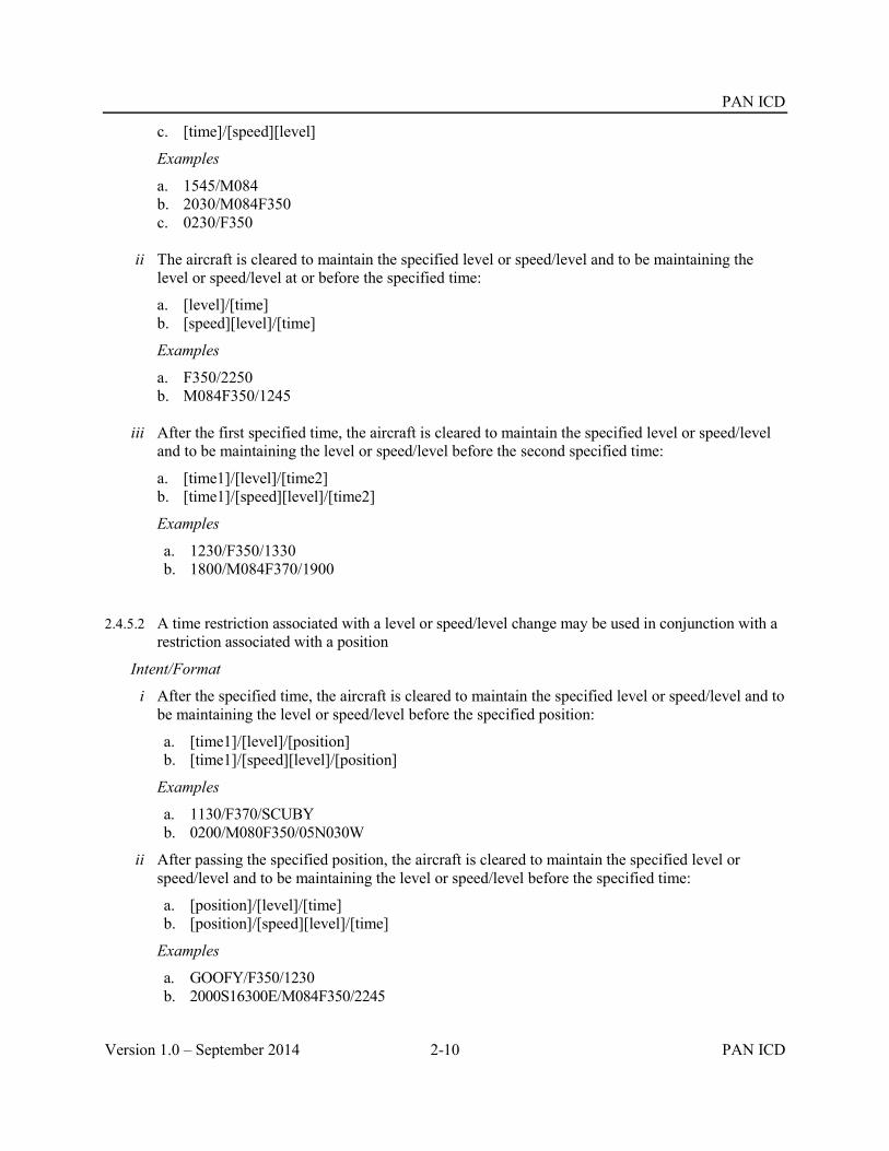
PAN ICD
Version 1.0 – September 2014 2-10 PAN ICD
c. [time]/[speed][level]
Examples
a. 1545/M084 b. 2030/M084F350 c. 0230/F350
ii The aircraft is cleared to maintain the specified level or speed/level and to be maintaining the
level or speed/level at or before the specified time:
a. [level]/[time] b. [speed][level]/[time]
Examples
a. F350/2250 b. M084F350/1245
iii After the first specified time, the aircraft is cleared to maintain the specified level or speed/level
and to be maintaining the level or speed/level before the second specified time:
a. [time1]/[level]/[time2] b. [time1]/[speed][level]/[time2]
Examples
a. 1230/F350/1330 b. 1800/M084F370/1900
2.4.5.2 A time restriction associated with a level or speed/level change may be used in conjunction with a restriction associated with a position
Intent/Format
i After the specified time, the aircraft is cleared to maintain the specified level or speed/level and to be maintaining the level or speed/level before the specified position:
a. [time1]/[level]/[position] b. [time1]/[speed][level]/[position]
Examples
a. 1130/F370/SCUBY b. 0200/M080F350/05N030W
ii After passing the specified position, the aircraft is cleared to maintain the specified level or speed/level and to be maintaining the level or speed/level before the specified time:
a. [position]/[level]/[time] b. [position]/[speed][level]/[time]
Examples
a. GOOFY/F350/1230 b. 2000S16300E/M084F350/2245
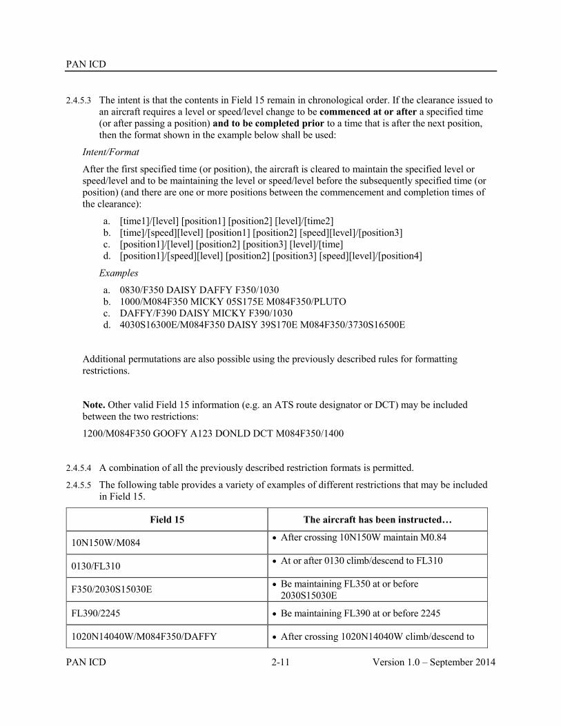
PAN ICD
PAN ICD 2-11 Version 1.0 – September 2014
2.4.5.3 The intent is that the contents in Field 15 remain in chronological order. If the clearance issued to an aircraft requires a level or speed/level change to be commenced at or after a specified time (or after passing a position) and to be completed prior to a time that is after the next position, then the format shown in the example below shall be used:
Intent/Format
After the first specified time (or position), the aircraft is cleared to maintain the specified level or speed/level and to be maintaining the level or speed/level before the subsequently specified time (or position) (and there are one or more positions between the commencement and completion times of the clearance):
a. [time1]/[level] [position1] [position2] [level]/[time2] b. [time]/[speed][level] [position1] [position2] [speed][level]/[position3] c. [position1]/[level] [position2] [position3] [level]/[time] d. [position1]/[speed][level] [position2] [position3] [speed][level]/[position4]
Examples
a. 0830/F350 DAISY DAFFY F350/1030 b. 1000/M084F350 MICKY 05S175E M084F350/PLUTO c. DAFFY/F390 DAISY MICKY F390/1030 d. 4030S16300E/M084F350 DAISY 39S170E M084F350/3730S16500E
Additional permutations are also possible using the previously described rules for formatting restrictions.
Note. Other valid Field 15 information (e.g. an ATS route designator or DCT) may be included between the two restrictions:
1200/M084F350 GOOFY A123 DONLD DCT M084F350/1400
2.4.5.4 A combination of all the previously described restriction formats is permitted.
2.4.5.5 The following table provides a variety of examples of different restrictions that may be included in Field 15.
Field 15 The aircraft has been instructed…
10N150W/M084 After crossing 10N150W maintain M0.84
0130/FL310 At or after 0130 climb/descend to FL310
F350/2030S15030E Be maintaining FL350 at or before 2030S15030E
FL390/2245 Be maintaining FL390 at or before 2245
1020N14040W/M084F350/DAFFY After crossing 1020N14040W climb/descend to

PAN ICD
Version 1.0 – September 2014 2-12 PAN ICD
FL350 and to maintain M0.84
Be maintaining FL350 and M0.84 prior to DAFFY
MICKY/M084F350 A123 DONLD M084F350/DAFFY
After crossing MICKY climb/descend to FL350 and to maintain M0.84
Be maintaining FL350 and M0.84 prior to DAFFY, where DAFFY is not the position after MICKY
2540N16300E/0005B Cross 2540N16300E at or before 0005
05N030W/0200L/F350
Cross 05N030W at 0200 or later After crossing 05N030W, climb/descent to
FL350
DAFFY/2200L/M085F370/DAISY/2300A Cross DAFFY at 2200 or later
After crossing DAFFY climb/descend to FL370 and to maintain M0.85
Be maintaining FL370 and M0.85 prior to DAISY
Cross DAISY at 2300
34S160E/1500B/F390 DCT 3200S16200E/1545A F390/1615 3025S16415E/1700L
Cross 34S160E at or before 1500
After crossing 34S160E climb/descend to FL390
Cross 3200S16200E at 1545
Be maintaining FL390 before 1615
Cross 3025S16415E at or after 1700
2.4.5.6 Under normal circumstances, restrictions in Field 15 would consist of:
A [position] or [time] that a change of speed and/or level is to commence; or
A [position] or [time] that a change of level or speed/level is to commence, as well as a [position] or [time] that a change of level or speed/level is to be completed by
However, when used in conjunction with a crossing condition in Field 14, it is also allowable for Field 15 to contain a restriction consisting only of a [position] or [time] that a change of level is to be completed by.
Field 14 Field 15 The aircraft has been instructed to…
PLUTO/1330F350F330A …F350/SCUBY … Climb to FL350 (and the aircraft will enter the ACI, or cross the FIR

PAN ICD
PAN ICD 2-13 Version 1.0 – September 2014
boundary, at or above FL330)
Be maintaining FL350 at or before SCUBY
1020N14030W/0400F370F350A … F370/0600 … Climb to FL370 (and the aircraft will enter the ACI, or cross the FIR boundary, at or above FL350)
Be maintaining FL370 at or before 0600


PAN ICD
PAN ICD 3-1 Version 1.0 – September 2014
Chapter 3 Communications and Support Mechanisms 3.1 Introduction
3.1.1 Coordination communication requirements are divided between the need for voice communications as well as data communications between ATS Units. It is anticipated that the continuing implementation of automated data communications between ATSUs will result in a reduction in the utilization of voice communications, with a corresponding increase in data communications.
3.1.2 AIDC messages can be exchanged over either AMHS and/or AFTN. The exchange of AIDC messages can also be supported by dedicated private communication lines.
3.2 Message Headers, Timers and ATSU Indicators
3.2.1 Message Headers.
3.2.1.1 The AFTN IA-5 Message Header, including the use of the Optional Data Field (ODF), will be utilized for the exchange of all AIDC messages. The AFTN message header (referred to as the AIDC message header within this document) is defined in ICAO Annex 10, Vol. II. When AMHS or a dedicated line is used, the ODF in AFTN IA-5 Message Header is still required to be included as the first line of the message text. Standard IA-5 Message Header including ODF should be employed at AMHS/AFTN gateway.
3.2.2 AFTN Priority
3.2.2.1 The AFTN priority indicator FF should normally be used for all AIDC messages, except for EMG, which should be assigned a priority indicator SS.
3.2.3 Optional Data Field (ODF)
3.2.3.1 The ODF provides a flexible means to transmit and respond to AIDC messages, without being affected by the communication processes along the network path.
3.2.3.2 ODF 1 has already been allocated for additional addressing uses, and is described in ICAO Annex 10, Vol II. ODF 2 and 3 have been defined for computer applications to convey message identification and message reference information and are adopted in this ICD.
3.2.3.3 The use of ODF is required to ensure the successful exchange of AIDC messages. When AMHS or AFTN/AMHS gateways are used for AIDC message exchanges, the ODFs specified in this ICD must be supported.
3.2.3.4 The proposed encoding has no impact on AFTN switching centers as they ignore this part of the origin line.
3.2.4 Addressing.
3.2.4.1 The Origin and Destination addresses of the AFTN header convey the direction and logical identity of the application processes exchanging AIDC data information. The application process must be aware of the AFTN addresses that are used for this function.
3.2.4.2 The first four characters in the address specify the location as per the ICAO Location Indicators (Doc 7910), while the next three characters specify an office/agency or a processor at the given location as per Doc 8585. The eighth character of the address indicates the end system application and is determined by the ATSU.
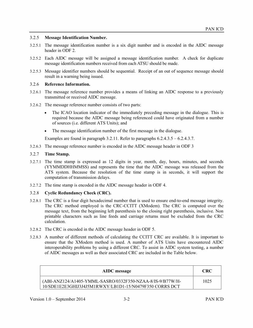
PAN ICD
Version 1.0 – September 2014 3-2 PAN ICD
3.2.5 Message Identification Number.
3.2.5.1 The message identification number is a six digit number and is encoded in the AIDC message header in ODF 2.
3.2.5.2 Each AIDC message will be assigned a message identification number. A check for duplicate message identification numbers received from each ATSU should be made.
3.2.5.3 Message identifier numbers should be sequential. Receipt of an out of sequence message should result in a warning being issued.
3.2.6 Reference Information.
3.2.6.1 The message reference number provides a means of linking an AIDC response to a previously transmitted or received AIDC message.
3.2.6.2 The message reference number consists of two parts:
The ICAO location indicator of the immediately preceding message in the dialogue. This is required because the AIDC message being referenced could have originated from a number of sources (i.e. different ATS Units); and
The message identification number of the first message in the dialogue.
Examples are found in paragraph 3.2.11. Refer to paragraphs 6.2.4.3.5 – 6.2.4.3.7.
3.2.6.3 The message reference number is encoded in the AIDC message header in ODF 3
3.2.7 Time Stamp.
3.2.7.1 The time stamp is expressed as 12 digits in year, month, day, hours, minutes, and seconds (YYMMDDHHMMSS) and represents the time that the AIDC message was released from the ATS system. Because the resolution of the time stamp is in seconds, it will support the computation of transmission delays.
3.2.7.2 The time stamp is encoded in the AIDC message header in ODF 4.
3.2.8 Cyclic Redundancy Check (CRC).
3.2.8.1 The CRC is a four digit hexadecimal number that is used to ensure end-to-end message integrity. The CRC method employed is the CRC-CCITT (XModem). The CRC is computed over the message text, from the beginning left parenthesis to the closing right parenthesis, inclusive. Non printable characters such as line feeds and carriage returns must be excluded from the CRC calculation.
3.2.8.2 The CRC is encoded in the AIDC message header in ODF 5.
3.2.8.3 A number of different methods of calculating the CCITT CRC are available. It is important to ensure that the XModem method is used. A number of ATS Units have encountered AIDC interoperability problems by using a different CRC. To assist in AIDC system testing, a number of AIDC messages as well as their associated CRC are included in the Table below.
AIDC message CRC
(ABI-ANZ124/A1405-YMML-SASRO/0332F350-NZAA-8/IS-9/B77W/H-10/SDE1E2E3GHIJ3J4J5M1RWXY/LB1D1-15/N0479F350 CORRS DCT
1025
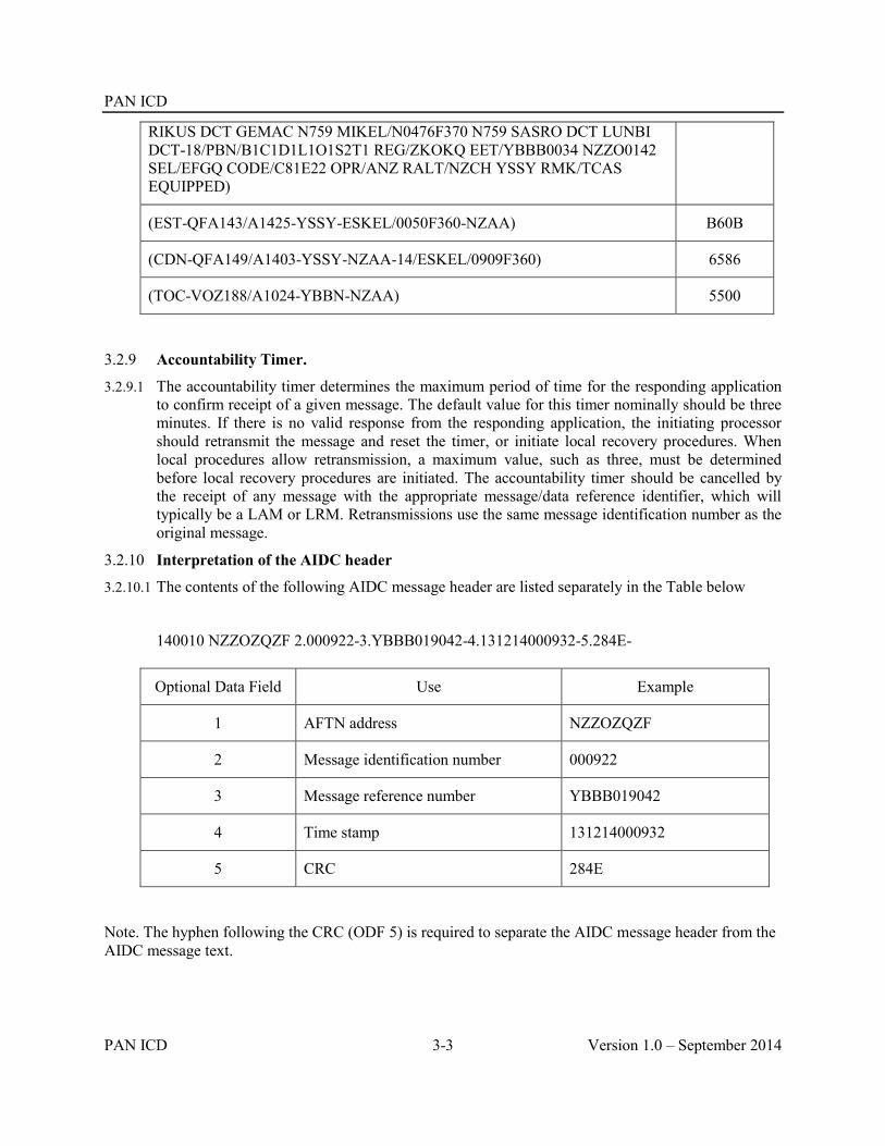
PAN ICD
PAN ICD 3-3 Version 1.0 – September 2014
RIKUS DCT GEMAC N759 MIKEL/N0476F370 N759 SASRO DCT LUNBI DCT-18/PBN/B1C1D1L1O1S2T1 REG/ZKOKQ EET/YBBB0034 NZZO0142 SEL/EFGQ CODE/C81E22 OPR/ANZ RALT/NZCH YSSY RMK/TCAS EQUIPPED)
(EST-QFA143/A1425-YSSY-ESKEL/0050F360-NZAA) B60B
(CDN-QFA149/A1403-YSSY-NZAA-14/ESKEL/0909F360) 6586
(TOC-VOZ188/A1024-YBBN-NZAA) 5500
3.2.9 Accountability Timer.
3.2.9.1 The accountability timer determines the maximum period of time for the responding application to confirm receipt of a given message. The default value for this timer nominally should be three minutes. If there is no valid response from the responding application, the initiating processor should retransmit the message and reset the timer, or initiate local recovery procedures. When local procedures allow retransmission, a maximum value, such as three, must be determined before local recovery procedures are initiated. The accountability timer should be cancelled by the receipt of any message with the appropriate message/data reference identifier, which will typically be a LAM or LRM. Retransmissions use the same message identification number as the original message.
3.2.10 Interpretation of the AIDC header
3.2.10.1 The contents of the following AIDC message header are listed separately in the Table below
140010 NZZOZQZF 2.000922-3.YBBB019042-4.131214000932-5.284E-
Optional Data Field Use Example
1 AFTN address NZZOZQZF
2 Message identification number 000922
3 Message reference number YBBB019042
4 Time stamp 131214000932
5 CRC 284E
Note. The hyphen following the CRC (ODF 5) is required to separate the AIDC message header from the AIDC message text.

PAN ICD
Version 1.0 – September 2014 3-4 PAN ICD
3.2.11 The following examples show two AIDC Messages encoded in accordance with the previous procedures.
The first AIDC message is EST message (message identification number 019042) transmitted by Brisbane Centre (YBBBZQZF) to Auckland Oceanic (NZZOZQZF) at time 131214000930:
FF NZZOZQZF 140009 YBBBZQZF 2.019042-4.131214000930-5.B60B- (EST-QFA143/A1425-YSSY-ESKEL/0050F360-NZAA)
The next AIDC message shows the ACP response from NZZO in reply to the EST message from the previous example.
Auckland Oceanic (NZZOZQZF) accepts the proposed coordination received from Brisbane Centre (YBBBZQZF) by sending an ACP message with message identification number 000922 from NZZOZQZF to YBBBZQZF at 131214000932. The message refers to the message transmitted earlier by YBBBZQZF, with message reference number YBBB019042. This message reference number is a combination of the location indicator (YBBB) and the message identification (019042) of the original message.
FF YBBBZQZF 140010 NZZOZQZF 2.000922-3.YBBB019042-4.131214000932-5.284E- (ACP-QFA143/A1425-YSSY-NZAA)
3.3 Engineering considerations
3.3.1 AIDC messages have traditionally been exchanged via the AFTN. However, the use of AMHS through AMHS/AFTN gateways may also be implemented.
3.3.2 Performance Criteria.
3.3.2.1 In order to effectively use the AIDC application for the interchange of ATC coordination data, ATSUs should monitor the performance of the communication links to ensure the required performance is achieved. This monitoring should measure the latency of the AIDC message traffic between ATS systems in terms of the time measured between message transmission at the originating ATS system and receipt of the message at the receiving ATS system.
3.3.2.2 The performance of the communications links should be such that 95% of all messages should be received within 12 seconds of transmission and 99.9% of all messages should be received within 30 seconds of transmission. In bilateral agreements, ATSUs, may agree on different performance requirements.
3.3.2.3 The communication signal speed between ATS systems using AFTN/AMHS should be greater than 2400 bps.
3.3.3 Measuring AIDC performance
3.3.3.1 Monitoring AIDC performance ensures that AFTN or AMHS delays are detected, as well as identifying AIDC interoperability issues with adjacent ATS Units. As described below, there are a number of different methods that may be used to measure AIDC performance.
3.3.3.2 One way performance for a transmitted AIDC message

PAN ICD
PAN ICD 3-5 Version 1.0 – September 2014
Calculate the difference between the time stamp in the message header of the transmitted message and the time stamp in the message header of the Application response (LAM/LRM):
Example:
ATSU Message Time stamp Transit time
ATSU 1 270646 YBBBZQZF 2.013490-4.140627064655-5.C997-
(EST-QFA147/A1551-YSSY-ESKEL/0727F390-NZAA)
140627064655
ATSU 2 270647 NZZOZQZF 2.024216-3.YBBB013490-4.140627064658-5.CF71-
(LAM)
140627064658 3 sec
3.3.3.3 One way performance for a received AIDC message
Calculate the difference between the time stamp in the message header of the received message and the time stamp in the measure header of the Application response (LAM/LRM):
Example:
ATSU Message Time stamp Transit time
ATSU 2 160503 NZZOZQZF 2.000751-4.140627064655-5.FCE9-
(EST-QFA146/A0277-NZAA-OLREL/0540F390-YSSY)
140627064655
ATSU 1 160502 YBBBZQZF 2.158853-3.NZZO000751-4. 140627064659-5.CF71-
(LAM)
140627064659 4 sec
Note. Instead of using the time stamp in the message header of the Application response, an alternative method is to use the network time stamp for the receipt of the EST message sent by ATSU 2.
3.3.3.4 Round trip performance for an AIDC message dialogue
Round trip performance can be calculated by:
Adding the one way performance for the individual messages in the dialogue; or
Comparing a combination of time stamps in message headers and network time stamps for the first and last messages in the AIDC dialogue.
An alternative method that uses information derived solely from the AIDC message is outlined below.
Calculate the difference between the time stamp in the message header of the first AIDC message in the dialogue and the time stamp in the message header of the Application

PAN ICD
Version 1.0 – September 2014 3-6 PAN ICD
response (LAM/LRM) that is sent when the Operational response to the first message is received :
Example:
ATSU Message Time stamp Transit time
ATSU 1 270646 YBBBZQZF 2.013490-4.140627064655-5.C997-
(EST-QFA147/A1551-YSSY-ESKEL/0727F390-NZAA)
140627064655
ATSU 2 270647 NZZOZQZF 2.000454-3.YBBB013490-4.140627064658-5.6454-
(ACP-QFA147/A1551-YSSY-NZAA)
140627064658 3 sec
ATSU 1 270647 YBBBZQZF 2.013491-3.NZZO000454-4.140627064700-5.CF71-
(LAM)
140627064700 2 sec
5 sec (Round trip)
3.3.3.5 Other parameters to consider monitoring may include the percentage of successful EST/ACP, PAC/ACP and CPL/ACP dialogues, the percentage of successful TOC/AOC exchanges, and the average delay for CPL and CDN negotiations.
3.3.3.6 Ongoing analysis of LRMs received is also recommended to identify any AIDC interoperability issues between adjacent ATS Units.
3.3.4 Recording of AIDC data.
3.3.4.1 The contents and time stamps of all AIDC messages should be recorded in both end systems in accordance with the current requirements for ATS messages.
3.3.4.2 Facilities should be available for the retrieval and display of the recorded data.
3.4 Test considerations
3.4.1 Non-operational test systems should be considered as an alternative to testing on the operational ATS system.
3.4.2 When required to use the operational system to conduct AIDC testing, the AIDC “test” messages should have the same format as operational messages, but be distinguishable from operational

PAN ICD
PAN ICD 3-7 Version 1.0 – September 2014
traffic by the use of non-operational call signs. These call signs should be specified in bilateral agreements.
3.5 Scheduled Maintenance and Failures
3.5.1 ANSPs should be aware that maintenance on AIDC and AFTN systems may have an operational effect on other ANSPs. Such an effect may for example include loss of the AIDC function due to flooding of messages or out of sequence messages following an AIDC server reboot. Any maintenance affecting the AIDC and AFTN systems shuld therefore be prior coordinated with the ANSP counterparts and backup procedures decided.
3.5.2 Failure of the AIDC and/or AFTN systems should be immediately notified to the ANSP counterparts and backup or recovery procedures implemented.


PAN ICD
PAN ICD 4-1 Version 1.0 – September 2014
Chapter 4 AIDC Messages 4.1 Introduction
4.1.1 This chapter describes the permitted fields and formats of AIDC messages. AIDC message fields conform to ICAO definitions contained in PANS-ATM Appendix 3 except as described below for Fields 14 and 15, as well as a “Text” field that is used in some AIDC messages.
4.1.2 ATS data in AIDC messages is enclosed between parentheses. Only one ATS message is permitted to be included in each transmission.
4.1.3 Unless specified otherwise by the ATSU, the optional elements in the AIDC message fields described in this chapter and shown in Table 4-6 should be made available in the system by the manufacturer and be user configurable.
4.2 Message Field Requirements
Fields in AIDC messages do not always require the full contents of the defined ICAO message field. This section specifies the usage of specific elements from message fields defined in the PANS-ATM as well as additional information that may be included in Fields 14 and 15.
4.2.1 Field 3 requirements.
4.2.1.1 All AIDC messages should use Field 3a (Message type) only.
4.2.1.2 Fields 3b (Message number) and 3c (Message reference data) are not used, since in AIDC messages the reference numbers contained in these fields are included in the Optional Data Field (ODF), option 2 and 3. See Chapter 3, Para 3.2.3.2.
4.2.2 Field 7 requirements.
4.2.2.1 Where Field 7 is required in an AIDC message, Field 7a (Aircraft Identification) must be included. Fields 7b (SSR Mode) and 7c (SSR Code) are optional but should be included if the information is available and applicable.
4.2.3 Field 13 requirements.
4.2.3.1 Where Field 13 is required in an AIDC message only Field 13a (Departure aerodrome), is required. Field 13b (Departure time) is not to be transmitted. The use of ZZZZ in Field 13 is supported.
4.2.4 Field 14 requirements
The following section describes the allowed contents of Field 14 (Estimate data), as well as providing examples of how Field 14 data can be incorporated in an AIDC message.
4.2.4.1 Field 14 may contain a number of mandatory and optional items. The following Table 4-1 provides an overview on the type of information that may be included in Field 14.
Table 4-1. Contents of Field 14
Data Example Mandatory/Optional Comment
Position
(14a)
46N150W
1545S16545E
M Normally a waypoint or system calculated position on or near the FIR or ACI boundary as agreed to

PAN ICD
Version 1.0 – September 2014 4-2 PAN ICD
GOOFY by bilateral agreement.
Field 14a is followed by an oblique stroke “/”
Estimated time
(14b)
2200 M The estimate for the position in 14a
Level
(14c)
A090
F330
F330F370
M The coordinated level of the aircraft
While 14c is mandatory, the support for the block level format is optional
Supplementary crossing data
(14d)
A120
F350
Included when applicable
Use in conjunction with 14e to indicate that an aircraft may be on climb or descent at, or within tolerances of, the FIR boundary
Crossing condition
(14e)
A
B
C
Included when applicable
(A) The aircraft may be on climb from the level specified in 14d
(B) The aircraft may be on descent from the level specified in 14d
(C) The aircraft is cruise climbing from the level specified in 14d.
The support for the cruise climb format is optional
Mach Number GM084
EM076
LM083
O Used when a Mach Number speed restriction has been assigned to the aircraft by ATC.
Offset and weather deviation
W25R
W100E
O30L
O When an offset or weather deviation is in effect, the position in 14a should be a position on the flight planned route, rather than the offset route
Note1. Each item of optional information in Field 14 is separated from the previous item by an oblique stroke “/”;
Note2. The order that the item is included in Field 14 is the order in which it is listed in Table 4-1. For example, if an AIDC message were to include an assigned Mach Number as well as a weather deviation, the Mach Number information would precede the weather deviation information in Field 14.
4.2.4.2 Supplementary Crossing Data and Crossing Conditions in Field 14
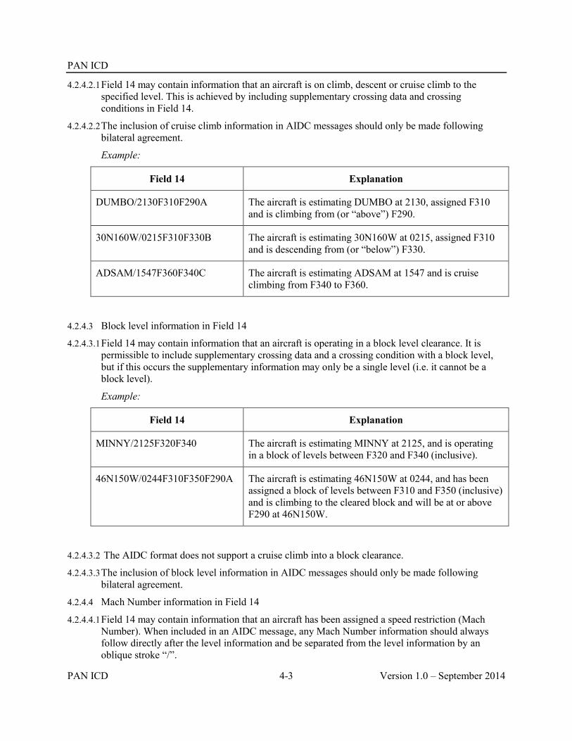
PAN ICD
PAN ICD 4-3 Version 1.0 – September 2014
4.2.4.2.1 Field 14 may contain information that an aircraft is on climb, descent or cruise climb to the specified level. This is achieved by including supplementary crossing data and crossing conditions in Field 14.
4.2.4.2.2 The inclusion of cruise climb information in AIDC messages should only be made following bilateral agreement.
Example:
Field 14 Explanation
DUMBO/2130F310F290A The aircraft is estimating DUMBO at 2130, assigned F310 and is climbing from (or “above”) F290.
30N160W/0215F310F330B The aircraft is estimating 30N160W at 0215, assigned F310 and is descending from (or “below”) F330.
ADSAM/1547F360F340C The aircraft is estimating ADSAM at 1547 and is cruise climbing from F340 to F360.
4.2.4.3 Block level information in Field 14
4.2.4.3.1 Field 14 may contain information that an aircraft is operating in a block level clearance. It is permissible to include supplementary crossing data and a crossing condition with a block level, but if this occurs the supplementary information may only be a single level (i.e. it cannot be a block level).
Example:
Field 14 Explanation
MINNY/2125F320F340 The aircraft is estimating MINNY at 2125, and is operating in a block of levels between F320 and F340 (inclusive).
46N150W/0244F310F350F290A The aircraft is estimating 46N150W at 0244, and has been assigned a block of levels between F310 and F350 (inclusive) and is climbing to the cleared block and will be at or above F290 at 46N150W.
4.2.4.3.2 The AIDC format does not support a cruise climb into a block clearance.
4.2.4.3.3 The inclusion of block level information in AIDC messages should only be made following bilateral agreement.
4.2.4.4 Mach Number information in Field 14
4.2.4.4.1 Field 14 may contain information that an aircraft has been assigned a speed restriction (Mach Number). When included in an AIDC message, any Mach Number information should always follow directly after the level information and be separated from the level information by an oblique stroke “/”.

PAN ICD
Version 1.0 – September 2014 4-4 PAN ICD
Example:
Field 14 Explanation
BUGGS/0349F350/GM085 The aircraft is estimating BUGGS at 0349 at F350 and has been instructed to maintain M0.85 or greater
4305N17510W/0215F310/EM076 The aircraft is estimating 4305N17510W at 0215 at F310 and has been instructed to maintain M0.76
4.2.4.4.2 The absence of speed information in Field 14 of an AIDC message provides advice that any previously notified speed has been cancelled.
Example:
Field 14 Explanation
SPEDY/1237F310F330B/LM083
Subsequently followed by:
SPEDY/1238F310
The aircraft is estimating SPEDY at 1237, assigned F310 and will cross SPEDY at or below F330, maintaining M0.83 or less.
The aircraft is now estimating SPEDY at 1238, is maintaining F310 (i.e. no longer on descent at SPEDY), and the Mach Number restriction has been cancelled.
4.2.4.4.3 The inclusion of Mach Number information in AIDC messages should only be made following bilateral agreement.
4.2.4.5 Offset and Weather Deviation Information in Field 14
4.2.4.5.1 Field 14 may contain information that an aircraft is subject to either a weather deviation or offset clearance. When included in an AIDC message, any offset and weather deviation information should always be the last information in Field 14, and should be separated from preceding information by an oblique stroke “/”.
4.2.4.5.2 It is important that the difference between an offset and a weather deviation is correctly understood. This difference is depicted in the diagram below.

PAN ICD
PAN ICD 4-5 Version 1.0 – September 2014
4.2.4.5.3 An offset is a flight trajectory that is parallel to the original route, offset by a specified distance and direction. Once an aircraft is established on the offset, separation may be applied solely based on the offset path.
4.2.4.5.4 A weather deviation permits an aircraft to operate anywhere between the original route and the specified distance and direction from the original route. Separation must therefore be applied to the entire airspace in which the aircraft has been cleared to operate in.
4.2.4.5.5 The following examples show various combinations of weather deviations and offsets, combined with other optional information allowed in Field 14.
Example:
Field 14 Explanation
2830S16300E/0140F330/W20L The aircraft is estimating 2830S16300E at 0140, maintaining F330, and has been cleared to deviate up to 20NM to the left of route.
GOOFY/2330F310/GM084/O30R The aircraft is estimating GOOFY at 2330, maintaining F310, instructed to maintain M0.84 or greater, and has been cleared to offset 30NM to the right of route.
41N040W/0215F310F330/W25E The aircraft is estimating 41N040W at 0215, is operating in a block of levels between F310 and F330 (inclusive), and has been cleared to deviate up to 25NM either side of route.
DAFFY/0215F310F350F370B/W100L The aircraft is estimating DAFFY at 0215, and has been assigned a block of levels between F310 and F350 (inclusive), will cross DAFFY at or below F370, and has been cleared to deviate up to 100NM to the left of route.
4.2.4.5.6 The absence of offset or weather deviation in Field 14 of an AIDC message provides advice that any previously notified off-track information has been cancelled.
Example:
Field 14 Explanation
34N040W/1519F330/W15R
Subsequently followed by:
34N040W/1520F330
The aircraft is deviating up to 15NM right of track.
The aircraft is back on track (and one minute later than previously coordinated).

PAN ICD
Version 1.0 – September 2014 4-6 PAN ICD
4.2.4.5.7 When an aircraft is offsetting or deviating, the coordination point included in Field 14a should be a position based on the flight planned route rather than the offset route. The estimate included in Field 14b shall be the estimate for the “abeam” position for the position included in Field 14a.
4.2.4.5.8 The inclusion of offsets and weather deviation information in AIDC messages should only be made following bilateral agreement. Depending on their operational requirements, some ATS Units may choose to only implement the weather deviation format. If applicable, this should also be specified in bilateral agreements.
4.2.5 Field 15 requirements
4.2.5.1 The following section describes the allowed contents of Field 15 (Route), as well as providing examples of how Field 15 data can be incorporated in an AIDC message.
4.2.5.2 A number of different AIDC messages (e.g. ABI, PAC, CPL, CDN and PCM) may contain Field 15 (Route) information. Depending on the AIDC message being used, this route information may be either the current cleared route of the aircraft, or a proposed amendment to it.
4.2.5.3 While Field 15 may be optional in an AIDC message (refer Table 4-6), if it is included, all Field 15 sub-fields (15a, b and c) must also be included.
Table 4-2. Contents of Field 15
Data Example Mandatory/Optional
Comment
Speed
(15a)
M084
N0488
M (Included in a flight plan as the initial requested speed for a flight).
In AIDC messaging:
if a speed has been specified in Field 14c, then the speed in Field 15a should be the same value; otherwise,
it should represent the expected speed of the aircraft at the coordination point included in Field 14a.

PAN ICD
PAN ICD 4-7 Version 1.0 – September 2014
Level
(15b)
F310
M (Included in a flight plan as the initial requested flight level for a flight).
In AIDC messaging:
if a block level has been specified in Field 14, then the level in Field 15a should be a single level within the block; otherwise,
it should be the level specified in Field 14c.
Route
(15c)
DAFFY HNL EGLL 3415S16000E 60N050W A123, AB456 BLI235100 M080F350 M084 F370 M084F370 1230
T DCT
M The route (or proposed route) of flight. It may contain any or all of the following elements:
Waypoint Navigation aid Aerodrome Latitude/longitude Latitude/longitude ATS route Place/bearing/distance Speed/level changes (See Note 2) Speed restriction Level restriction Speed/Level restriction (See Note 2) Time associated with a restriction. May
include a suffix of “A”, “B” or “L” Truncation indicator (‘T’) Direct to
Note 1: The contents of Field 15c are defined in PANS-ATM Appendix 3, with the exception of level/time/speed restrictions which are described within this document in paragraph 2.4 Restriction Formats. Planned speed/level changes from the filed FPL are included in some AIDC implementations although they do not reflect the current cleared profile of the aircraft.
Note 2: Flight planned speed/level changes and level/time/speed restrictions as defined in 2.4 Restriction Formats cannot both be included in Field 15 because in some cases they both use the same format. ATS Units should specify in bilateral agreements which group of information (if any) will be supported.
4.2.5.4 At the minimum, Field 15 in an AIDC message should commence at a position prior to the ACI associated with the adjacent FIR. Some ATS Units may include route information commencing at the Departure aerodrome.
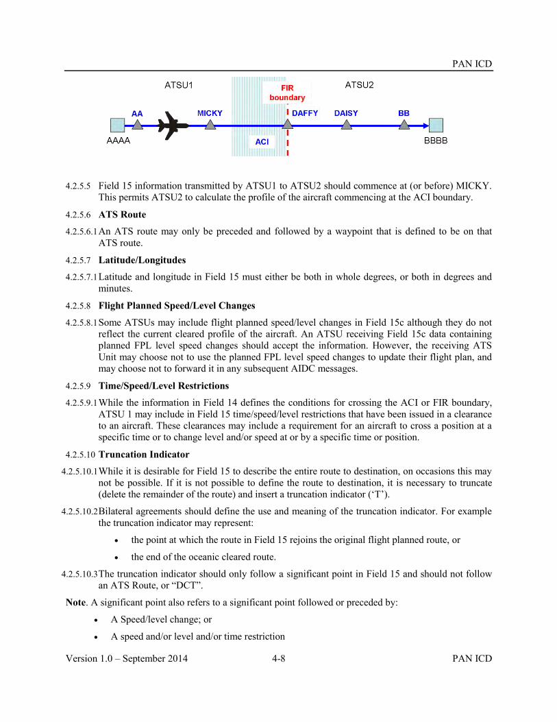
PAN ICD
Version 1.0 – September 2014 4-8 PAN ICD
4.2.5.5 Field 15 information transmitted by ATSU1 to ATSU2 should commence at (or before) MICKY. This permits ATSU2 to calculate the profile of the aircraft commencing at the ACI boundary.
4.2.5.6 ATS Route
4.2.5.6.1 An ATS route may only be preceded and followed by a waypoint that is defined to be on that ATS route.
4.2.5.7 Latitude/Longitudes
4.2.5.7.1 Latitude and longitude in Field 15 must either be both in whole degrees, or both in degrees and minutes.
4.2.5.8 Flight Planned Speed/Level Changes
4.2.5.8.1 Some ATSUs may include flight planned speed/level changes in Field 15c although they do not reflect the current cleared profile of the aircraft. An ATSU receiving Field 15c data containing planned FPL level speed changes should accept the information. However, the receiving ATS Unit may choose not to use the planned FPL level speed changes to update their flight plan, and may choose not to forward it in any subsequent AIDC messages.
4.2.5.9 Time/Speed/Level Restrictions
4.2.5.9.1 While the information in Field 14 defines the conditions for crossing the ACI or FIR boundary, ATSU 1 may include in Field 15 time/speed/level restrictions that have been issued in a clearance to an aircraft. These clearances may include a requirement for an aircraft to cross a position at a specific time or to change level and/or speed at or by a specific time or position.
4.2.5.10 Truncation Indicator
4.2.5.10.1 While it is desirable for Field 15 to describe the entire route to destination, on occasions this may not be possible. If it is not possible to define the route to destination, it is necessary to truncate (delete the remainder of the route) and insert a truncation indicator (‘T’).
4.2.5.10.2 Bilateral agreements should define the use and meaning of the truncation indicator. For example the truncation indicator may represent:
the point at which the route in Field 15 rejoins the original flight planned route, or
the end of the oceanic cleared route.
4.2.5.10.3 The truncation indicator should only follow a significant point in Field 15 and should not follow an ATS Route, or “DCT”.
Note. A significant point also refers to a significant point followed or preceded by:
A Speed/level change; or
A speed and/or level and/or time restriction

PAN ICD
PAN ICD 4-9 Version 1.0 – September 2014
Examples of Field 15c
SY L521 AA Navaid, ATS Route
Note that both “SY” and “AA” are defined on airway L521
SY L521 GEROS 32S160E 3425S16300E LUNBI AA Navaid, ATS Route, waypoint, lat/long (dd), lat/long (ddmm)
SY GEROS GEROS045100 ESKEL L521 AA Place/bearing/distance
SY L521 GEROS/M085F370 L521 AA DCT BB Speed/level change, DCT
SY L521 LUNBI T
SY L521 GEROS 32S160E 3425S16300E T
SY L521 LUNBI/M085F370 T
Truncation indicator
SY L521 GEROS/F370 L521 F370/LUNBI AA
SY GEROS/2245L 32S160E ESKEL/M085F390 AA
SY L521 M084F350/GEROS/1230A ESKEL/M083 L521 AA
Restrictions
4.2.6 Field 16 Requirements
4.2.6.1 Where Field 16 is required in an AIDC message, only Field 16a (Destination aerodrome), is required. Field 16b (Total estimated elapsed time) and Field 16c (Alternate aerodrome(s)) are not to be transmitted. The use of ZZZZ in Field 16 is supported.
4.2.7 Field 18 Requirements
4.2.7.1 Field 18 should contain other information from the current flight plan and is used to update the flight plan at the receiving ATSU.
4.2.7.2 When transmitting Field 18 in an AIDC message, all Field 18 indicators should be included, even if the change only affects data in an individual Field 18 indicator. However, ATS Units may agree by bilateral agreement to omit specific indicators (e.g. EET/) if required. If omitting indicators, ATS Units should have due regard to the potential effect to downstream ATS Units.
4.2.7.3 The contents of Field 18 in AIDC messages should be specified in bilateral agreements between ATS Units.
Note: Some legacy implementations allowed provision for the modification of individual sub fields by communicating only that specific subfield. This is not recommended practice.
4.2.7.4 In some AIDC messages, Field 18 may contain only a RMK/ indicator which is used to convey free text data information. This applies to the MAC, EMG, LRM and MIS messages.

PAN ICD
Version 1.0 – September 2014 4-10 PAN ICD
4.3 AIDC message groups
4.3.1 From a technical and operational perspective it is advantageous to standardize AIDC implementation to the full extent possible. This document identifies a group of messages as a “core” message set in Table 4-3, which is recommended to be supported by all ATSUs. This will aid standardization of system and procedure development.
4.3.2 It is nevertheless acknowledged that even a limited message set implementation, such as only CPL and ACP, can bring significant benefits to ATS units. Some ATSUs may, due to technical, financial, or operational reasons, have a need to gradually implement the AIDC message set or may even determine that not all messages in the core message set are required.
4.3.3 Unless specified otherwise by the ATSU, the non-core messages shown in Table 4-3 should be supported by the manufacturer in ground systems and their availability be configured by the ATS Unit as required.
4.3.4 The specific AIDC messages to be used between ATSUs should be included in bilateral agreements.
Table 4-3. AIDC Messages
Core Non-core Message Class Message
X Notification ABI (Advance Boundary Information)
X Coordination CPL (Current Flight Plan)
X Coordination EST (Coordination Estimate)
X Coordination PAC (Preliminary Activate)
X Coordination MAC (Coordination Cancellation)
X Coordination CDN (Coordination Negotiation)
X Coordination ACP (Acceptance)
X Coordination REJ (Rejection)
X Coordination PCM (Profile Confirmation Message)
X Coordination PCA (Profile Confirmation Acceptance)
X Coordination TRU ( Track Update)
X Transfer of Control TOC (Transfer of Control)
X Transfer of Control AOC (Acceptance of Control)
X General Information EMG (Emergency)

PAN ICD
PAN ICD 4-11 Version 1.0 – September 2014
Core Non-core Message Class Message
X General Information MIS (Miscellaneous)
X Application Management LAM (Logical Acknowledgement Message)
X Application Management LRM (Logical Rejection Message)
X Application Management ASM (Application Status Monitor)
X Application Management FAN ( FANS Application Message)
X Application Management FCN (FANS Completion Notification)
X Surveillance Data Transfer
ADS (Surveillance ADS-C)
4.4 Notification messages
4.4.1 ABI (Advance Boundary Information).
4.4.1.1 Purpose.
4.4.1.2 An ABI message is transmitted to provide information on a flight to the receiving ATSU. The purpose of the ABI is to synchronize the flight plan information held between two ATS Units.
4.4.1.3 The transmission of the initial ABI will normally be triggered at an agreed time or position prior to the common boundary or ACI, or possibly by a change in flight state. Before coordination occurs, amendments to information contained in a previously transmitted ABI should be notified by the transmission of another ABI.
4.4.1.4 Message format.
ATS Field Description
3 Message type
7 Aircraft identification
13 Departure aerodrome
14 Estimate data
16 Destination aerodrome
22 Amendment field
Field 22 should contain as a minimum the following fields:
9 Number, type of aircraft and wake turbulence category
15 Route

PAN ICD
Version 1.0 – September 2014 4-12 PAN ICD
Field 22 may optionally include any or all of the following fields:
8 Flight rules and type of flight
10 Equipment
18 Other information
Example
An ABI message containing the minimum contents of Field 22, with full route details to destination.
(ABI-IBE6175-LEMD-41N040W/0700F330-KMIA
-9/B744/H
-15/M084F350 41N030W 41N040W 41N050W 40N060W 38N065W DANER A699 NUCAR DCT HEATT
An ABI message containing a supplementary crossing condition and Mach Number in Field 14, a truncated Field 15 containing a level restriction, and an agreed subset of Field 18:
(ABI-ICE615-BIKF-62N030W/0700F350F310A/GM080-KJFK
-8/IS
-9/B752/M
-10/SDIJ5RXW/SD1
-15/M080F350 62N030W 60N040W/M080F370 57N050W DCT OYSTR DCT STEAM T
-18/PBN/A1L1)
An ABI containing a weather deviation in Field 14, a speed/level change in Field 15 and the entire Field 18 from the original FPL:
(ABI-ANZ716/A1565-YSSY-ESKEL/0743F370/W20R-NZAA
-8/IS
-9/A320/M
-10/SDE1E3FGHIM2RW/LB1
-15/N0448F370 EVONN L521 ESKEL/N0448F390 L521 LUNBI DCT
-18/PBN/A1C1D1O1S2T1 REG/ZKOJI EET/YBBB0009 NZZO0121 SEL/HLAM CODE/C8178C OPR/ANZ RALT/YSNF RMK/TCAS EQUIPPED)
4.5 Coordination messages
4.5.1 CPL (Current Flight Plan)
4.5.1.1 Purpose.

PAN ICD
PAN ICD 4-13 Version 1.0 – September 2014
4.5.1.1.1 A CPL message is used to initiate coordination for a flight.
4.5.1.1.2 The transmission of the CPL message will normally be triggered at an agreed time or position prior to the common boundary or ACI, or possibly by a change in flight state.
4.5.1.1.3 The ATSU receiving the CPL message should either agree to the proposed coordination by responding with an ACP message, or negotiate the proposed coordination by responding with a CDN message.
4.5.1.1.4 A coordination dialogue initiated by a CPL message may only be closed by an ACP message.
4.5.1.2 Message format.
ATS Field Description
3 Message type
7 Aircraft identification
8 Flight rules and type of flight
9 Number, type of aircraft and wake turbulence category
10 Equipment
13 Departure aerodrome
14 Estimate data
15 Route
16 Destination aerodrome
18 Other information
Example
A CPL message containing a block level with a supplementary crossing condition in Field 14, and an agreed subset of Field 18:
(CPL-UAL815-IS
-B773/H-SDIJ5RXW/SD1
-LFPG-54N030W/1417F350F370F330A
-M080F350 54N020W 54N030W 54N040W 52N050W DCT CRONO DCT DOTTY
-KIAD
-PBN/A1L1 REG/N456UA SEL/KLBF)
A CPL message containing a block level and a weather deviation in Field 14, and a time restriction in Field 15:
(CPL-ICE680/A1437-IS
-B752/M-SWXRGIDFHY/LB1
-KSEA-6852N06414W/0418F370F390/W30E

PAN ICD
Version 1.0 – September 2014 4-14 PAN ICD
-M079F370 6852N06414W BOPUT/0430B 6900N06000W 6900N05000W 6800N04000W
6600N03000W HEKLA
-BIKF
-PBN/A1B2B3B4B5D1L1S1 NAV/RNVD1A1 DOF/131124 REG/TFLLX SEL/DSHK RALT/CYEG BGSF)
4.5.2 EST (Coordination Estimate)
4.5.2.1 Purpose.
4.5.2.1.1 An EST message is used to initiate coordination for a flight.
4.5.2.1.2 The transmission of the EST message is used in conjunction with (and generally following) an ABI message and is triggered at an agreed time or position prior to the common boundary or ACI, or possibly by a change in flight state.
4.5.2.1.3 The only valid response to an EST message is an ACP message, which closes the coordination dialogue.
4.5.2.2 Message Format
ATS Field Description
3 Message type
7 Aircraft identification
13 Departure aerodrome
14 Estimate data
16 Destination aerodrome
Example
(EST-DLH454-EDDF-BOPUT/1248F360/LM083-KSFO)
(EST-QFA811/A2277-WSSS-20N070E/1417F350F370/W20L-YAYT)
4.5.3 PAC (Preliminary Activate)
4.5.3.1 Purpose.
4.5.3.1.1 A PAC message is used to initiate coordination for a flight that has not yet departed to comply with the approval request procedure, specified in PANS-ATM Para 10.1.2.3. This would normally occur if the departure point is close to the FIR or ACI boundary and preflight coordination is required.
4.5.3.1.2 Because the departure point is close to the boundary, the transmission of a PAC message would normally be triggered by a change in flight state.

PAN ICD
PAN ICD 4-15 Version 1.0 – September 2014
4.5.3.1.3 Where a PAC contains enough optional fields to capture any flight plan updates that may have occurred it is not normally preceded by an ABI message. However, this is considered a local implementation issue and should be determined by bi-lateral agreement.
4.5.3.1.4 A coordination dialogue initiated by a PAC message may only be closed by an ACP message.
4.5.3.2 Message Format
ATS Field Description
3 Message type
7 Aircraft identification
13 Departure aerodrome
14 Estimate data
16 Destination aerodrome
22 Amendment field
Field 22 may optionally include any or all of the following fields
8 Flight rules and type of flight
9 Number, type of aircraft and wake turbulence category
10 Equipment
15 Route
18 Other information
Example
An example of an abbreviated PAC message:
(PAC-ANZ763-YSNF-TEKEP/0250F360F001A-YSSY)
An example of a PAC message containing all message fields:
(PAC-ATN460/A4440-FJDG-LATEP/1822F310F001A-WSAP -8/IN -9/B752/M -10/ SDIRXW/S -15/N0473F370 DCT NKW R348 LATEP/M080F350 R348 KADAP/N0489F290 P627 DABAP/N0467F370 N628 PKU R469 TAROS/M080F370 DCT PIMOK W401 KK DCT PU DCT -18/PBN/A1B2C2D2O2 NAV/RNVD1E2A1 DOF/131212 REG/N753CX EET/YMMM0027 SEL/GSQR OPR/ATN ORGN/KLITATNX RMK/TCAS EQUIPPED)
4.5.4 MAC (Cancellation of Notification and/or Coordination)
4.5.4.1 Purpose.

PAN ICD
Version 1.0 – September 2014 4-16 PAN ICD
4.5.4.1.1 A MAC message is transmitted to advise an ATSU that any notification and/or coordination previously received for a flight is no longer relevant to that ATSU.
4.5.4.1.2 A MAC message should only be transmitted to an ATSU that has previously received notification and/or coordination for a flight. While a MAC message might be transmitted after a flight has been cancelled, the MAC message should not to be considered as equivalent to a CNL message as its purpose is not to cancel the flight plan.
4.5.4.2 Message Format
ATS Field Description
3 Message type
7 Aircraft identification
13 Departure aerodrome
16 Destination aerodrome
22 Amendment field
Field 22 may optionally include any or all of the following fields:
14 Estimate Data
18 Other information (limited to RMK/)
Field 14 containing the estimate data previously transmitted may be included in the MAC message. It may be used if required, to correctly identify the flight concerned by the MAC, when appropriate. If a MAC message is transmitted as a result of a diversion to a new destination (i.e. such that the receiving ATSU is no longer affected by the flight), Field 16 – Destination aerodrome – should contain the destination contained in the original Notification and/or coordination messages.
Example
(MAC-BCA789-EGKK-KLAX)
(MAC-THA989-VTBD-YMML-18/RMK/DIVERTED TO YPDN)
(MAC-FJI910/A1452-YSSY-NFFN-14/UBLIN/2330F370)
4.5.5 CDN (Coordination Negotiation)
4.5.5.1 Purpose.
4.5.5.1.1 A CDN message is used to propose amendments to previously agreed coordination conditions or coordination proposed in a CPL message or a CDN message.
4.5.5.1.2 An initial coordination dialogue following a CPL message is always terminated by an ACP message; otherwise an ATSU receiving a CDN message can indicate that the proposed revision is not acceptable (by replying with an REJ message) or propose an amendment to the proposed coordination by replying with a CDN message.
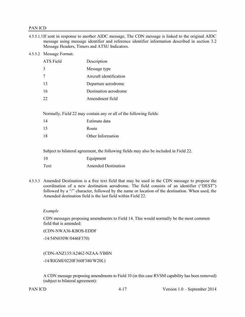
PAN ICD
PAN ICD 4-17 Version 1.0 – September 2014
4.5.5.1.3 If sent in response to another AIDC message, The CDN message is linked to the original AIDC message using message identifier and reference identifier information described in section 3.2 Message Headers, Timers and ATSU Indicators.
4.5.5.2 Message Format.
ATS Field Description
3 Message type
7 Aircraft identification
13 Departure aerodrome
16 Destination aerodrome
22 Amendment field
Normally, Field 22 may contain any or all of the following fields:
14 Estimate data
15 Route
18 Other Information
Subject to bilateral agreement, the following fields may also be included in Field 22.
10 Equipment
Text Amended Destination
4.5.5.3 Amended Destination is a free text field that may be used in the CDN message to propose the coordination of a new destination aerodrome. The field consists of an identifier (“DEST”) followed by a “/” character, followed by the name or location of the destination. When used, the Amended destination field is the last field within Field 22.
Example
CDN messages proposing amendments to Field 14. This would normally be the most common field that is amended:
(CDN-NWA36-KBOS-EDDF
-14/54N030W/0446F370)
(CDN-ANZ135/A2462-NZAA-YBBN
-14/RIGMI/0220F360F380/W20L)
A CDN message proposing amendments to Field 10 (in this case RVSM capability has been removed) (subject to bilateral agreement):

PAN ICD
Version 1.0 – September 2014 4-18 PAN ICD
(CDN-QFA43/A4422-YSSY-NZAA
-10/SDE2E3GHIRYZ/LB1)
A CDN message proposing amendments to Fields 14 and 15:
(CDN-BAW32N-KMIA-EGGL
-14/37N040W/0201F360
-15/M085F360 32N050W 37N040W 42N030W 45N020W OMOKO GUNSO GAPLI UL620 GIBSO)
A CDN message proposing amendments to field 18:
(CDN-BAW242-MMMX-EGLL
-18/PBN/A1 DOF/120412 REG/GBNLI EET/KZHU0054 LPPO0546 CZQX0606 EGGX0643 49N020W0732 BEDRA0757 GUNSO0813 EGTT0833 SEL/BPCE ORGN/EGLLBAWH RALT/CYQX EIDW RMK/TCAS)
CDN messages proposing an amended destination (subject to bilateral agreement):
(CDN-KAL823-RJAA-NZCH
-15/LTO G591 AA-DEST/NZAA)
(CDN-MAPLE1-PKMJ-ZZZZ
-14/MARTI/2200F310-15/MARTI 02N168E
-DEST/0150N16745E)
4.5.5.4 The last two examples demonstrate a CDN message proposing a new route to an amended destination. The first of these examples shows a change in route and destination, with no change in Field 14 (i.e. the proposed re-route occurs after the boundary position). The second example shows a change of route with a corresponding change to Field 14. The “DEST/” included in this example refers to the proposed destination, rather than the original “ZZZZ” destination that may have been included in the flight plan. Refer to Chapter 6, Implementation Guidance Material, for the methodology in proposing a diversion to a new destination.
4.5.6 ACP (Acceptance)
4.5.6.1 Purpose.
4.5.6.1.1 An ACP message is used to confirm that the coordination proposed in a received CPL, CDN, EST or PAC message is acceptable and to close the coordination dialogue. The agreed coordination conditions are updated in accordance with the proposed coordination.

PAN ICD
PAN ICD 4-19 Version 1.0 – September 2014
4.5.6.1.2 An ACP message is linked to the original AIDC message using message identifier and reference identifier information described in section 3.2 Message Headers, Timers and ATSU Indicators.
4.5.6.2 Message Format.
ATS Field Description
3 Message type
7 Aircraft identification
13 Departure aerodrome
16 Destination aerodrome
Example
(ACP-ACA860-NZAA-KSFO)
(ACP-UAL816/A3312-YSSY-KLAX)
4.5.7 REJ (Rejection)
4.5.7.1 Purpose.
4.5.7.1.1 An REJ message is used to reject the coordination proposed in a received CDN message and to close the coordination dialogue. The previously agreed coordination conditions remain unchanged.
4.5.7.1.2 An REJ message may not be used to close an initial coordination dialogue
4.5.7.1.3 An REJ message is linked to the original CDN message using message identifier and reference identifier information described in section 3.2 Message Headers, Timers and ATSU Indicators.
4.5.7.2 Message Format.
ATS Field Description
3 Message type
7 Aircraft Identification
13 Departure Aerodrome
16 Destination Aerodrome
Example
(REJ-AAL780-KJFK-EGLL)
(REJ-BAW32N/A2262-KMIA-EGGL)
4.5.8 PCM (Profile Confirmation Message) 4.5.8.1 Purpose.

PAN ICD
Version 1.0 – September 2014 4-20 PAN ICD
4.5.8.1.1 The PCM is used as a final conformance check between the transferring ATSU and the receiving ATSU to enable detection of coordination errors and to ensure that the receiving ATSU has the most up to date information on the aircraft.
4.5.8.1.2 At the minimum, the PCM is used to confirm boundary estimate information, but may also be used to confirm other flight plan information as well.
4.5.8.1.3 The transmission of the PCM should be automatically triggered at an agreed time or position approaching the common boundary or ACI.
4.5.8.1.4 The only valid response to a PCM is a PCA message.
4.5.8.2 Message Format.
ATS Field Description
3 Message type
7 Aircraft identification
13 Departure aerodrome
14 Estimate data
16 Destination aerodrome
The PCM may optionally include any or all of the following fields:
8 Flight rules and type of flight
9 Number, type of aircraft and wake turbulence category
10 Equipment
15 Route
18 Other information.
Example
A PCM containing mandatory Field 14 information only:
(PCM-QFA43/A2233-YSSY-ESKEL/1417F350-NZAA)
A PCM containing mandatory Field 14 information as well as Field 10:
(PCM-UAL815/A2211-YSSY-2801S16300E/2255F310-KLAX
-10/SDE3FGHIJ3J5M1M3RWXY/LB1D1)
A PCM containing all allowable fields:
(PCM-UAL840/A5124-YSSY-TEKEP/2231F330-KLAX
-8/IS

PAN ICD
PAN ICD 4-21 Version 1.0 – September 2014
-9/B744/H
-10/SDE3FGHIJ3J5M1M3RWXY/LB1D1
-15/N0493F310 3345S15114E 3346S15125E LHI/N0489F330 B450 NF G224 NN B581
BAXIL/N0490F350 B581 WACOS/N0488F370 B581 WINTY/N0488F390 B581 FICKY
C1177 ROSIN/N0360F120
-18/PBN/A1B1C1D1L1O1S2 DOF/131212 REG/N199UA EET/YBBB0013 NZZO0118 SEL/ASEP CODE/A18B5D OPR/UAL PER/D RMK/TCAS)
4.5.9 PCA (Profile Confirmation Acceptance)
4.5.9.1 Purpose.
4.5.9.1.1 A PCA message is used to confirm that the data in a received PCM either corresponds with the data held by the receiving ATSU, or the data held by the receiving ATSU has been updated appropriately.
4.5.9.1.2 A PCA message is linked to the original PCM using message identifier and reference identifier information described in section 3.2 Message Headers, Timers and ATSU Indicators.
4.5.9.2 Message Format.
ATS Field Description
3 Message type
7 Aircraft identification
13 Departure aerodrome
16 Destination aerodrome
Example
(PCA-UAL815-YSSY-KLAX)
(PCA-QFA43/A2233-YSSY-NZAA)
4.5.10 TRU (Track Update)
4.5.10.1 Purpose.
4.5.10.1.1 A TRU message is used to coordinate amendments to previously agreed coordination conditions, or other flight-related information, where prior coordination of the change(s) is not required.
4.5.10.1.2 Unlike the CDN message, there is no operational response to the TRU message, and so use of this message must be in strict accordance with bilateral agreements.
4.5.10.2 Message Format.
ATS Field Description
3 Message type

PAN ICD
Version 1.0 – September 2014 4-22 PAN ICD
7 Aircraft Identification
13 Departure Aerodrome
16 Destination Aerodrome
Text Track Data
4.5.10.2.1 Track data is a free text field used in the TRU message to permit the transfer of updated information from one ATSU to another. This field contains a number of elements which are described below. Each element consists of an “identifier” and a value separated by a “/” character.
4.5.10.2.2 All of the elements within the Track data field are optional, and multiple elements may be included, separated by a single <space> character. Track data will contain at least one element. When multiple elements are to be transmitted in a single TRU message, the order of the elements within the Track data field is the order in which they are listed below. Unused elements are not included in the Track data field.
4.5.10.2.2.1 Requested Flight Level (RFL)
This element is preceded by the identifier ‘RFL’ and contains the aircraft’s most recent requested level. Block levels and cruise climbs are supported as defined in Chapter 2, Purpose, Policy and Units of Measurement.
Example
RFL/F390
RFL/A090
RFL/F310F330
RFL/F330F310C
4.5.10.2.2.2 Present Level (PRL)
This element is preceded by the identifier ‘PRL’ and contains the aircraft’s last reported level.
Example
PRL/F390
PRL/A090
4.5.10.2.2.3 Heading (HDG)
This element is preceded by the identifier ‘HDG’ and contains the magnetic heading that has been assigned to the aircraft, expressed as a three digit number between 001 and 360 (inclusive).
Example
HDG/080
4.5.10.2.2.4 Cleared Flight Level (CFL)
This element is preceded by the identifier ‘CFL’ and contains the amended level that the aircraft has been assigned. Block levels and cruise climbs in accordance with Chapter 2, Purpose, Policy and Units of Measurement are also supported.

PAN ICD
PAN ICD 4-23 Version 1.0 – September 2014
Example
CFL/F330
CFL/F310F330
CFL/F310F330F210A
CFL/F330F310C
4.5.10.2.2.5 Speed (SPD)
This element is preceded by the identifier ‘SPD’ and contains details of the speed (Mach Number or Indicated airspeed) that the aircraft has been assigned.
Mach Numbers are expressed as “M” followed by 3 figures giving the true Mach Number or to the nearest .01 Mach.
Indicated airspeeds are expressed as “I” followed by 4 figures giving the Indicated Airspeed in knots.
To cancel an assigned speed that had been previously coordinated, the SPD identifier is followed by a “/” character, followed by a zero (0).
Example
SPD/M084
SPD/I0250
SPD/0
4.5.10.2.2.6 Direct to (DCT)
This element is preceded by the identifier “DCT” and contains the position that the aircraft has been cleared directly to.
Example
DCT/MICKY
DCT/30S160E
4.5.10.2.2.7 Off track deviation (OTD)
This element is preceded by the identifier ‘OTD’ and contains the details of any off track clearance that has been issued to the aircraft. The format of the off track deviation is as described in Chapter 2, Purpose, Policy and Units of Measurement, Para 2.3.9.1; i.e.
a single character providing advice as to whether the clearance is an offset (O) or a weather deviation (W); and
an off track distance associated with this clearance: a direction, indicating left (L) or right (R) or, in the case of weather deviation, either side
of track (E); and when including Offset information in and AIDC message, the direction “E” (either side
of track) should not be used To cancel a previously coordinated off track deviation, the OTD identifier is followed by an oblique stroke “/”, followed by a zero (0).

PAN ICD
Version 1.0 – September 2014 4-24 PAN ICD
Example
OTD/W20R
OTD/O30L
OTD/0
Examples
TRU message notifying that an aircraft is requesting an amended level (which is not currently available):
(TRU-ICE456-BIKF-EGPF-RFL/F370)
TRU messages notifying of a weather deviation, subsequently followed by the cancellation of the weather deviation:
(TRU-UAL73-NTAA-KLAX-OTD/W20R)
(TRU-UAL73-NTAA-KLAX-OTD/0)
TRU messages notifying that an aircraft is initially on a heading of 115, assigned F270, and at reduced speed (250 knots), subsequently followed by notification that the aircraft has been re-cleared direct to GEROS, assigned F370, and the speed restriction has been removed:
(TRU-QFA43/A2244-YSSY-NZAA-HDG/115 CFL/F270 SPD/I0250)
(TRU-QFA43/A2244-YSSY-NZAA-CFL/370 SPD/0 DCT/GEROS)
4.6 Transfer of control messages
4.6.1 TOC (Transfer of Control)
4.6.1.1 Purpose.
4.6.1.1.1 The TOC message is sent to propose executive control of a flight to the receiving ATSU.
4.6.1.2 Message Format
ATS Field Description
3 Message type
7 Aircraft identification
13 Departure aerodrome
16 Destination aerodrome
Example
(TOC-TAP451-LPPT-KJFK)
(TOC-QFA135/A2217-YMML-NZCH)

PAN ICD
PAN ICD 4-25 Version 1.0 – September 2014
4.6.2 AOC (Acceptance of Control)
4.6.2.1 Purpose.
4.6.2.1.1 The AOC message is transmitted in response to a received TOC message to indicate acceptance of executive control of a flight.
4.6.2.2 Message Format.
ATS Field Description
3 Message type
7 Aircraft identification
13 Departure aerodrome
16 Destination aerodrome
Example
(AOC-TAP451-LPPT-KJFK)
(AOC-QFA135/A2217-YMML-NZCH)
4.7 General information messages
4.7.1 EMG (Emergency)
4.7.1.1 Purpose.
4.7.1.1.1 The EMG message is used when it is considered that the contents require immediate attention by the receiving ATSU.
4.7.1.1.2 When the EMG does not refer to a specific flight, a functional address may be used (where this functionality is supported) to present the information to the appropriate ATS position. Where such an address is used it is preceded by an oblique stroke “/” to differentiate it from aircraft identification.
4.7.1.1.3 The following are examples of circumstances which could justify the use of an EMG message.
a) Reports of emergency calls or emergency locator transmission reports;
b) Messages concerning hijack or bomb warnings;
c) Messages concerning serious illness or disturbance among passengers;
d) Sudden alteration in flight profile due to technical or navigational failure;
e) Communications failure.
4.7.1.2 Message format.
ATS Field Description
3 Message type
7 Aircraft identification (or functional address)
18 Other information (limited to RMK/)

PAN ICD
Version 1.0 – September 2014 4-26 PAN ICD
Example
(EMG-UAL123-RMK/Free Text)
(EMG-/ASUP-RMK/Free Text)
4.7.2 MIS (Miscellaneous)
4.7.2.1 Purpose.
4.7.2.1.1 The MIS message is used to transmit operational information which cannot be formatted to comply with any other message type and for plain language statements.
4.7.2.1.2 When the MIS does not refer to a specific flight, a functional address may be used (where this functionality is supported) to present the information to the appropriate ATS position. Where such an address is used it is preceded by an oblique stroke “/” to differentiate it from an aircraft’s identification.
4.7.2.2 Message format.
ATS Field Description
3 Message type
7 Aircraft identification (or functional address)
18 Other information (limited to RMK/)
Examples
(MIS-NWA456-RMK/Free Text)
(MIS-/ASUP-RMK/Free Text)
4.8 Application management messages
4.8.1 LAM (Logical Acknowledgement Message)
4.8.1.1 Purpose.
4.8.1.1.1 The LAM is transmitted in response to each AIDC message (except for another LAM or LRM) that has been received, and found free of syntax and semantic errors.
4.8.1.1.2 A LAM is linked to the original AIDC message using message identifier and reference identifier information described in Chapter 3, Communications and Support Mechanisms.
4.8.1.1.3 Non-receipt of a LAM may require local action.
4.8.1.2 Message Format.
ATS Field Description
3 Message type

PAN ICD
PAN ICD 4-27 Version 1.0 – September 2014
Example
(LAM)
For examples of the way in which the LAM is linked to the original AIDC message refer to Chapter 6, Implementation Guidance Material.
4.8.2 LRM (Logical Rejection Message)
4.8.2.1 Purpose.
4.8.2.1.1 The LRM is transmitted in response to each AIDC message not eligible for a LAM to be sent.
4.8.2.1.2 An LRM is linked to the original AIDC message using message identifier and reference identifier information described in Chapter 3, Communications and Support Mechanisms.
4.8.2.1.3 The LRM will identify the first message field found that contains invalid information if this field information is available.
4.8.2.1.4 Receipt of an LRM may require local corrective action.
4.8.2.2 Message Format.
ATS Field Description
3 Message type
18 Other information (limited to RMK/)
4.8.2.2.1 Field 18 is used to convey technical information, and will only use the RMK/ sub-field. This text will comprise an error code, supporting text and the message field number in which the error occurred (where applicable).
4.8.2.2.2 The following format is used in the RMK/ sub-field of the LRM to report errors:
<error code>/<field number>/<invalid text>
4.8.2.2.3 The <error code> should contain the appropriate error code number from Chapter 5, Error Codes, Table 5-1. The <error code> is described using up to three numeric characters without leading zeros. When multiple errors are detected in an AIDC message, only a single LRM should be generated in response. This LRM would usually contain the error code of the first error detected.
4.8.2.2.4 The <field number> will contain the field number corresponding to the error code extracted from Table 5-1. Where multiple field numbers are assigned to an error code, only the first field number containing the error will be sent. Where no field number is referenced in Table 5-1, the <field number> sub-field will be empty. The field number can be described using up to six alphanumeric characters.
Note: Some ATSUs may not support a non-numeric <field number> (e.g. “HEADER”), and will leave this sub-field blank. Whilst this is acceptable in order to preserve backwards compatibility with existing systems, the preferred implementation is for any non-numeric field numbers for Table 5-1 to be supported within the LRM.
4.8.2.2.5 The <invalid text> will contain the error text corresponding to the error code extracted from Table 5-1 (not including any of ‘explanatory text’ that may have been included in Table 5-1). If

PAN ICD
Version 1.0 – September 2014 4-28 PAN ICD
the specific error can be identified, it may optionally be appended to the Table 5-1 error text. The invalid text field can contain up to 256 characters, and may contain an oblique stroke “/”.
Note: Some ATSUs may not include the error text from Table 5-1, in the <invalid text> field of transmitted LRMs, and will leave this sub-field blank. Whilst this is acceptable in order to preserve backwards compatibility with existing systems, the preferred option is for the LRM <invalid text> field to at least contain the error text from Table 5-1.
4.8.2.2.6 The following shows a number of LRM examples. Where more than one LRM format is shown, the format of the first one is the preferred option.
Example
(LRM-RMK/1/HEADER/INVALID SENDING UNIT)
OR
(LRM-RMK/1/ /INVALID SENDING UNIT)
(See Note following paragraph 4.8.2.2.4)
(LRM-RMK/17/16/INVALID AERODROME DESIGNATOR)
OR
(LRM-RMK/17/16/)
(See Note following paragraph 4.8.2.2.5)
(LRM-RMK/57//INVALID MESSAGE LENGTH)
(LRM-RMK/27/15/ INVALID LAT/LONG 130S165E)
(The actual error “130S165E” may be optionally appended to the error text from Table 5-1, see Para 4.8.2.2.5).
For examples of the way in which the LRM is linked to the original AIDC message refer to Chapter 6, Implementation Guidance Material)
4.8.3 ASM (Application Status Monitor)
4.8.3.1 Purpose.
4.8.3.1.1 The ASM message is transmitted to an adjacent ATSU to confirm that end-to-end messaging is available with that ATSU.
4.8.3.1.2 The transmission of an ASM message normally occurs when no AIDC messages (including Application messages) have been received from the adjacent ATSU within a specified time as defined in bilateral agreement.
4.8.3.2 Message Format.
ATS Field Description
3 Message type
Example
(ASM)

PAN ICD
PAN ICD 4-29 Version 1.0 – September 2014
4.8.4 FAN (FANS Application Message)
4.8.4.1 Purpose.
4.8.4.1.1 The FAN is transmitted by one ATSU (generally the transferring ATSU) to another ATSU (generally the receiving ATSU) to provide the required information necessary to establish CPDLC and/or ADS-C connections with FANS-1/A equipped aircraft. Use of the FAN message significantly reduces the number of data link messages normally required to achieve a data link transfer using the Address Forwarding process, as well as improving the reliability and performance associated with data link transfers.
4.8.4.2 Message Format.
ATS Field Description
3 Message type
7 Aircraft identification
13 Departure aerodrome
16 Destination aerodrome
Text Application data
4.8.4.2.1 Application data is a free text field used in the FAN message to permit the transfer of FANS-1/A logon information from one ATSU to another. This field contains a number of elements which are described below. Each element consists of an “identifier” and a value which are separated by a “/” character. The abbreviation used for the identifier corresponds to the associated ICAO abbreviation (where one exists), otherwise the three character MTI (Message Type Identifier) contained in the logon is used (refer to ARINC 622 for a listing of various MTIs)
4.8.4.2.2 The order of the elements within the FAN message is the order that they are listed below, with consecutive elements being separated by a single <space> character. Although some elements within the Application data field may be “optional”, they should be included if the corresponding data is available (i.e. if the ATSU transmitting the FAN message has this information available, either from a logon or a FAN message). This is for the benefit of downstream ATSUs that may use the information within these optional elements. If the data is not available for an optional element, that element is not to be included in the FAN message.
4.8.4.2.3 Additional information concerning the elements described below is contained in Chapter 6, Implementation Guidance Material.
4.8.4.2.4 Standard message identifier (SMI)
4.8.4.2.4.1 This mandatory element is preceded by the identifier ‘SMI’, and contains information relating to the address to which uplink messages are routed to in the avionics. The value of the SMI sent in the FAN message is the downlink SMI as it was received in either the most recently received logon or FAN message.
4.8.4.2.4.2 Allowable values for the SMI are listed in ARINC 620. Examples of SMIs include “FML”, “FMR”, “FMD”, FM3” and “AFD”.

PAN ICD
Version 1.0 – September 2014 4-30 PAN ICD
Example
SMI/FMD
4.8.4.2.5 Aircraft identification
4.8.4.2.5.1 This mandatory element is preceded by the identifier ‘FMH’ and contains the aircraft identification as it was received in either the most recently received logon or FAN message.
Example
FMH/MAS123
4.8.4.2.6 Aircraft registration
4.8.4.2.6.1 This mandatory element is preceded by the identifier ‘REG’ and contains the registration details of the aircraft – including the hyphen if applicable – as it was received in either the most recently received logon or FAN message. While a hyphen is not permitted in the registration in other AIDC messages, it is necessary in the FAN message in order to allow data link messages to be correctly addressed to the aircraft. Any “padding” in the registration contained in the AFN logon (e.g. preceding periods “.”) must not be included in the FAN message.
Example
Registration format in logon Registration format in FAN message
.N12345 REG/N12345
.9V-ABC REG/9V-ABC
Note the periods preceding the registration letters are not included in the FAN message
4.8.4.2.7 Aircraft Address (ICAO 24 bit code)
4.8.4.2.7.1 This optional element is preceded by the identifier ‘CODE’ and contains the six character hexadecimal translation of the 24 bit aircraft address as it was received in either the most recently received logon or FAN message.
Example
CODE/ABC123
4.8.4.2.8 Aircraft position information
4.8.4.2.8.1 This optional element is preceded by the identifier ‘FPO’ and contains the position of the aircraft as determined by the ATSU at the time of transmission of the FAN message (if this information is available). The position of the aircraft is expressed as a latitude/longitude in either dd[NS]ddd[EW] or ddmm[NS]dddmm[EW] format. The position that may have been provided by the aircraft in a previous logon should not be included in the FAN message, because it is most likely no longer accurate

PAN ICD
PAN ICD 4-31 Version 1.0 – September 2014
Example
FPO/23S150E
FPO/0823N11025E
4.8.4.2.9 ATS Application and Version Number
4.8.4.2.9.1 There will usually be multiple elements associated with the ATS Application and Version number (i.e. CPDLC and ADS-C). Occurrences of this element are preceded by the identifier ‘FCO’ which describes the ATS data link application(s) available in the avionics, as they were received in a logon or a previously received FAN message. The FAN message must include at least one ATS data link application – a separate identifier is used for each available application. These elements may be transmitted in any order, separated by a single <space>.
4.8.4.2.9.2 The value associated with the FCO identifier consists of three letters to describe the application name immediately followed by (i.e. with no intervening spaces) two figures characters to represent the associated version number. Possible values for the three letters are “ATC” (for CPDLC) or “ADS” (for ADS-C), and the possible range of version numbers is 01 to 99.
Example
FCO/ATC01 FCO/ADS01
FCO/ADS01
4.8.4.2.10 The second example above illustrates a FAN message with the ADS-C application only. This may be either because the aircraft is not CPDLC equipped, or because the FAN is being used with an adjacent ATSU to enable monitoring using ADS-C by that ATSU when the aircraft is only entering the Area of Common Interest (ACI).
Example
(FAN-ACA870-CYUL-LFPG
-SMI/AFD FMH/ACA870 REG/C-GOJA FPO/53N035W FCO/ATC01 FCO/ADS01)
(FAN-UAL951-EBBR-KIAD
-SMI/FML FMH/UAL951 REG/N123UA CODE/A254B3 FCO/ADS01)
(FAN-ANZ123/A2213-NZAA-KLAX
-SMI/FML FMH/ANZ123 REG/ZK-NJP FCO/ADS01)
(FAN-SIA221-WSSS-YSSY
-SMI/FMD FMH/SIA221 REG/9M-MRP CODE/A254B3 FPO/1214S11223E FCO/ATC01 FCO/ADS01)

PAN ICD
Version 1.0 – September 2014 4-32 PAN ICD
4.8.4.2.11 ATSUs should ensure that at least two of the ACID, REG, or CODE elements are used to ensure that the logon information contained in the FAN message is associated with the correct flight plan.
Note 1. If the FAN message is being transmitted to permit the next ATS unit to establish a CPDLC connection, it should not be sent until after an appropriate CPDLC Next Data Authority message (NDA) has been transmitted to the aircraft, either by allowing a reasonable time for delivery of the NDA message or waiting until a successful MAS (MAS/S) message has been received in response to the transmission of the NDA message.
Note 2. Where an aircraft enters an adjacent ATSU’s ACI but does not actually enter the ATSU’s airspace and a FAN message is sent to the adjacent ATSU to enable monitoring using ADS-C then the FCO identifier for the CPDLC application should not be included.
4.8.5 FCN (FANS Completion Notification)
4.8.5.1 Purpose.
4.8.5.1.1 The FCN message is transmitted by the either the transferring or receiving ATSU to provide information concerning the CPDLC Connection status of the aircraft.
4.8.5.1.2 The FCN message is transmitted by the transferring ATSU when their CPDLC Connection with the aircraft is terminated, providing notification to the receiving ATSU that they are now the CPDLC “Current Data Authority”. The FCN message may also be transmitted by the receiving ATSU to provide notification of their establishment of (or failure to establish) a CPDLC Connection.
4.8.5.1.3 An FCN message transmitted by the receiving ATSU may also (optionally) include contact/monitor frequency information to be issued to the aircraft by the transferring ATSU.
4.8.5.2 Message Format.
ATS Field Description
3 Message type
7 Aircraft identification
13 Departure aerodrome
16 Destination aerodrome
Text Communication Status
4.8.5.2.1 Communication Status is a free text field used in the FCN message to permit the transfer of CPDLC connection status and (optionally) frequency information from one ATSU to another. This field may contain a number of elements which are described below. Each element consists of an “identifier” and a value which are separated by a “/” character. Separate elements are separated by a single < space> character.
4.8.5.2.2 CPDLC Connection Status identifier (CPD)
4.8.5.2.2.1 This mandatory element is preceded by the identifier “CPD” and contains a single integer value which is used to provide information concerning an aircraft’s CPDLC Connection
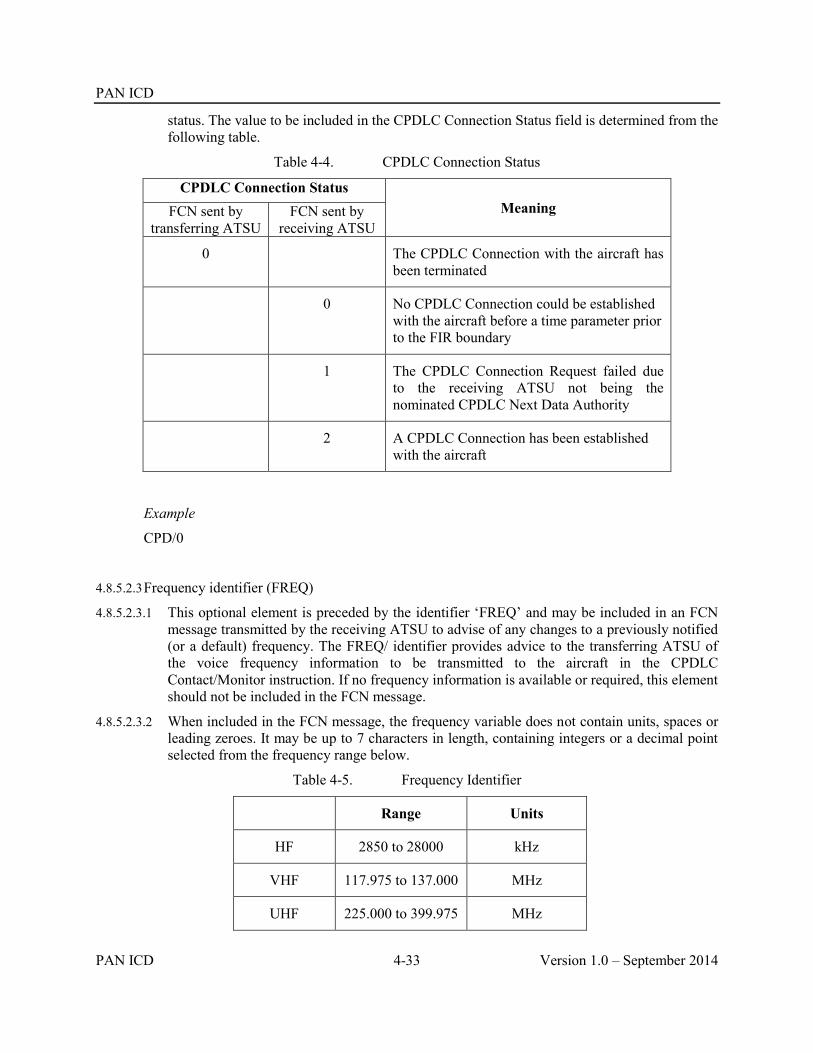
PAN ICD
PAN ICD 4-33 Version 1.0 – September 2014
status. The value to be included in the CPDLC Connection Status field is determined from the following table.
Table 4-4. CPDLC Connection Status
CPDLC Connection Status Meaning FCN sent by
transferring ATSU FCN sent by
receiving ATSU
0 The CPDLC Connection with the aircraft has been terminated
0 No CPDLC Connection could be established with the aircraft before a time parameter prior to the FIR boundary
1 The CPDLC Connection Request failed due to the receiving ATSU not being the nominated CPDLC Next Data Authority
2 A CPDLC Connection has been established with the aircraft
Example
CPD/0
4.8.5.2.3 Frequency identifier (FREQ)
4.8.5.2.3.1 This optional element is preceded by the identifier ‘FREQ’ and may be included in an FCN message transmitted by the receiving ATSU to advise of any changes to a previously notified (or a default) frequency. The FREQ/ identifier provides advice to the transferring ATSU of the voice frequency information to be transmitted to the aircraft in the CPDLC Contact/Monitor instruction. If no frequency information is available or required, this element should not be included in the FCN message.
4.8.5.2.3.2 When included in the FCN message, the frequency variable does not contain units, spaces or leading zeroes. It may be up to 7 characters in length, containing integers or a decimal point selected from the frequency range below.
Table 4-5. Frequency Identifier
Range Units
HF 2850 to 28000 kHz
VHF 117.975 to 137.000 MHz
UHF 225.000 to 399.975 MHz

PAN ICD
Version 1.0 – September 2014 4-34 PAN ICD
Example
FREQ/117.975
Example of FCN message
FCN messages transmitted by the receiving ATSU:
The CPDLC Connection request for SIA221 was unsuccessful
(FCN-SIA221-YSSY-WSSS-CPD/0)
The CPDLC Connection request for QFA44 was unsuccessful because the receiving ATSU was not the nominated next data authority
(FCN-QFA44/A1145-NZAA-YSSY-CPD/1)
The CPDLC Connection request for ANZ15 was successful. The Contact/Monitor voice frequency is 13261
(FCN-ANZ15/A4466-KLAX-NZAA-CPD/2 FREQ/13261)
FCN message transmitted by the transferring ATSU:
The CPDLC Connection with ICE615 has been terminated
(FCN-ICE615-BIKF-KJFK-CPD/0)
4.9 Surveillance Data Transfer Service Messages
4.9.1 ADS (Surveillance ADS-C)
4.9.1.1 Purpose.
4.9.1.1.1 The ADS message is used to transfer information contained in an ADS-C report from one ATSU to another.
4.9.1.2 Message Format.
ATS Field Description
3 Message type
7 Aircraft identification
13 Departure aerodrome
16 Destination aerodrome
Text ADS-C Data

PAN ICD
PAN ICD 4-35 Version 1.0 – September 2014
4.9.1.2.1 ADS-C data is a free text field used in the ADS message to permit the transfer of information contained in an ADS-C report from one ATSU to another. The data field consists of an identifier ’ADS’ followed by an oblique stroke “/”, followed by a text string containing specific text extracted from the encoded ACARS ADS-C report received from the aircraft.
4.9.1.2.2 Any hyphen in the registration of the aircraft in the ACARS ADS-C report is included in the ADS message. Unlike the FAN message, any “padding” in the registration contained in the ACARS ADS-C report (e.g. preceding periods “.”) MUST be included in the ADS message.
4.9.1.2.3 The ADS-C data field may also be used to indicate that no further ADS messages will be sent to the receiving ATSU for the flight. To indicate this state the ADS identifier is followed by an oblique stroke “/”, followed by a “0” (zero). The trigger for this would be by bilateral agreement (e.g. when an ADS-C report has been received that places the aircraft outside the ACI and the ADS-C Predicted Route group indicates that the aircraft will not re-enter the ACI).
4.9.1.2.4 The specific text to be included in the AIDC ADS message is described in Chapter 6, Implementation Guidance Material.
Example
(ADS-ANZ90/A2233-RJAA-NZAA
-ADS/.ZK-OKC030007FF946B6F6DC8FC044B9D0DFC013B80DA88FC0A64F9E4438B4AC8FC000E34D0EDC00010140F3E86)
(ADS-ANZ90/A2233-RJAA-NZAA
-ADS/0)

PAN ICD
PAN ICD 4-36 Version 1.0 – September 2014
Table 4-6. PAN AIDC Messages and their Field Composition
Message 3
a b c
7
a b c
8
a b
9
a b c
10
a b
13
a b
14
a b c d e
15
a b c
16
a b c 18 19 20 21
22
8
a b
9
a b c
10
a b
14
a b c d e
15
a b c 18 Text
ABI M - - MOO M - MMMOO M - - OO MMM OO MMM O
CPL M - - MOO MM MMM MM M - MMMOO MMM M - - M
EST M - - MOO M - MMMOO M - -
PAC M - - MOO M - MMMOO M - - OO OOO OO OOO O
MAC M - - MOO M - M - - OOOOO O
CDN M - - MOO M - M - - OO OOOOO OOO O O
ACP M - - MOO M - M - -
REJ M - - MOO M - M - -
PCM M - - MOO M - MMMOO M - - OO OOO OO OOO O
PCA M - - MOO M - M -
TRU M - - MOO M - M - - M

PAN ICD
PAN ICD 4-37 Version 1.0 – September 2014
Message 3
a b c
7
a b c
8
a b
9
a b c
10
a b
13
a b
14
a b c d e
15
a b c
16
a b c 18 19 20 21
22
8
a b
9
a b c
10
a b
14
a b c d e
15
a b c 18 Text
TOC M - - MOO M - M - -
AOC M - - MOO M - M - -
EMG M - - MOO M
MIS M - - MOO M
LAM M - -
LRM M - - M
ASM M - -
FAN M - - MOO M - M - - M
FCN M - - MOO M - M - - M
ADS M - - MOO M - M - - M


PAN ICD
PAN ICD 5-1 Version 1.0 – September 2014
Chapter 5 Error Codes 5.1 Introduction
5.1.1 A set of error codes has been developed for those messages contained in the AIDC message set. A list of the codes, associated field number and error text is contained in the table below. This information is for inclusion in any Logical Rejection Message transmitted in response to the reception of an AIDC message containing an error.
5.1.2 It is recommended that when a specific error code is available, the receiving ATSU should use the specific error code instead of general error codes, such as Error Code 57.
Table 5-1. Error Codes
Error Code Field Number Error Text
1 HEADER INVALID SENDING UNIT (e.g., AFTN Address)
2 HEADER INVALID RECEIVING UNIT (e.g., AFTN Address)
3 HEADER INVALID TIME STAMP
4 HEADER INVALID MESSAGE ID
5 HEADER INVALID REFERENCE ID
6 7 INVALID ACID
7 7 DUPLICATE ACID
8 7 UNKNOWN FUNCTIONAL ADDRESS
9 7 INVALID SSR MODE
10 7 INVALID SSR CODE
11 8 INVALID FLIGHT RULES
12 8 INVALID FLIGHT TYPE
13 9 INVALID AIRCRAFT MODEL
14 9 INVALID WAKE TURBULENCE CATEGORY
15 10 INVALID EQUIPMENT DESIGNATOR
16 10 INVALID SSR EQUIPMENT DESIGNATOR
17 13, 16 INVALID AERODROME DESIGNATOR
18 13 INVALID DEPARTURE AERODROME
19 16 INVALID DESTINATION AERODROME
20 RESERVED
21 RESERVED
22 13, 16 TIME DESIGNATOR PRESENT WHEN NOT

PAN ICD
Version 1.0 – September 2014 5-2 PAN ICD
EXPECTED
23 14 INVALID TIME DESIGNATOR
24 14 MISSING TIME DESIGNATOR
25 14 INVALID BOUNDARY POINT DESIGNATOR
26 14, 15 INVALID ENROUTE POINT
27 14, 15 INVALID LAT/LONG DESIGNATOR
28 14, 15 INVALID NAVAID FIX
29 14, 15 INVALID LEVEL DESIGNATOR
30 14, 15 MISSING LEVEL DESIGNATOR
31 14 INVALID SUPPLEMENTARY CROSSING DATA
32 14 INVALID SUPPLEMENTARY CROSSING LEVEL
33 14 MISSING SUPPLEMENTARY CROSSING LEVEL
34 14 INVALID CROSSING CONDITION
35 14 MISSING CROSSING CONDITION
36 15 INVALID SPEED/LEVEL DESIGNATOR
37 15 MISSING SPEED/LEVEL DESIGNATOR
38 15 INVALID SPEED DESIGNATOR
39 15 MISSING SPEED DESIGNATOR
40 15 INVALID ROUTE ELEMENT DESIGNATOR
41 15 INVALID ATS ROUTE/SIGNIFICANT POINT DESIGNATOR
42 15 INVALID ATS ROUTE DESIGNATOR
43 15 INVALID SIGNIFICANT POINT DESIGNATOR
44 15 FLIGHT RULES INDICATOR DOES NOT FOLLOW SIGNIFICANT POINT
45 15 ADDITIONAL DATA FOLLOWS TRUNCATION INDICATOR
46 15 INCORRECT CRUISE CLIMB FORMAT
47 15 CONFLICTING DIRECTION
48 18 INVALID OTHER INFORMATION ELEMENT
49 RESERVED
50 22 INVALID AMENDMENT FIELD DATA
51 MISSING FIELD nn (See Note 2)
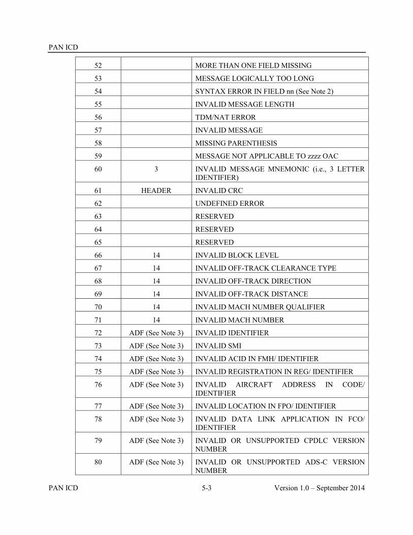
PAN ICD
PAN ICD 5-3 Version 1.0 – September 2014
52 MORE THAN ONE FIELD MISSING
53 MESSAGE LOGICALLY TOO LONG
54 SYNTAX ERROR IN FIELD nn (See Note 2)
55 INVALID MESSAGE LENGTH
56 TDM/NAT ERROR
57 INVALID MESSAGE
58 MISSING PARENTHESIS
59 MESSAGE NOT APPLICABLE TO zzzz OAC
60 3 INVALID MESSAGE MNEMONIC (i.e., 3 LETTER IDENTIFIER)
61 HEADER INVALID CRC
62 UNDEFINED ERROR
63 RESERVED
64 RESERVED
65 RESERVED
66 14 INVALID BLOCK LEVEL
67 14 INVALID OFF-TRACK CLEARANCE TYPE
68 14 INVALID OFF-TRACK DIRECTION
69 14 INVALID OFF-TRACK DISTANCE
70 14 INVALID MACH NUMBER QUALIFIER
71 14 INVALID MACH NUMBER
72 ADF (See Note 3) INVALID IDENTIFIER
73 ADF (See Note 3) INVALID SMI
74 ADF (See Note 3) INVALID ACID IN FMH/ IDENTIFIER
75 ADF (See Note 3) INVALID REGISTRATION IN REG/ IDENTIFIER
76 ADF (See Note 3) INVALID AIRCRAFT ADDRESS IN CODE/ IDENTIFIER
77 ADF (See Note 3) INVALID LOCATION IN FPO/ IDENTIFIER
78 ADF (See Note 3) INVALID DATA LINK APPLICATION IN FCO/ IDENTIFIER
79 ADF (See Note 3) INVALID OR UNSUPPORTED CPDLC VERSION NUMBER
80 ADF (See Note 3) INVALID OR UNSUPPORTED ADS-C VERSION NUMBER
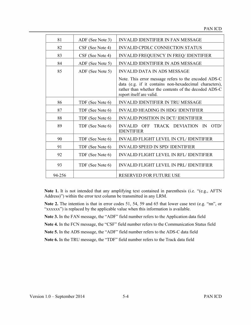
PAN ICD
Version 1.0 – September 2014 5-4 PAN ICD
81 ADF (See Note 3) INVALID IDENTIFIER IN FAN MESSAGE
82 CSF (See Note 4) INVALID CPDLC CONNECTION STATUS
83 CSF (See Note 4) INVALID FREQUENCY IN FREQ/ IDENTIFIER
84 ADF (See Note 5) INVALID IDENTIFIER IN ADS MESSAGE
85 ADF (See Note 5) INVALID DATA IN ADS MESSAGE
Note. This error message refers to the encoded ADS-C data (e.g. if it contains non-hexadecimal characters), rather than whether the contents of the decoded ADS-C report itself are valid.
86 TDF (See Note 6) INVALID IDENTIFIER IN TRU MESSAGE
87 TDF (See Note 6) INVALID HEADING IN HDG/ IDENTIFIER
88 TDF (See Note 6) INVALID POSITION IN DCT/ IDENTIFIER
89 TDF (See Note 6) INVALID OFF TRACK DEVIATION IN OTD/ IDENTIFIER
90 TDF (See Note 6) INVALID FLIGHT LEVEL IN CFL/ IDENTIFIER
91 TDF (See Note 6) INVALID SPEED IN SPD/ IDENTIFIER
92 TDF (See Note 6) INVALID FLIGHT LEVEL IN RFL/ IDENTIFIER
93 TDF (See Note 6) INVALID FLIGHT LEVEL IN PRL/ IDENTIFIER
94-256 RESERVED FOR FUTURE USE
Note 1. It is not intended that any amplifying text contained in parenthesis (i.e. “(e.g., AFTN Address)”) within the error text column be transmitted in any LRM.
Note 2. The intention is that in error codes 51, 54, 59 and 65 that lower case text (e.g. “nn”, or “xxxxxx”) is replaced by the applicable value when this information is available.
Note 3. In the FAN message, the “ADF” field number refers to the Application data field
Note 4. In the FCN message, the “CSF” field number refers to the Communication Status field
Note 5. In the ADS message, the “ADF” field number refers to the ADS-C data field
Note 6. In the TRU message, the “TDF” field number refers to the Track data field

PAN ICD
PAN ICD 6-1 Version 1.0 – September 2014
Chapter 6 Implementation Guidance Material 6.1 Introduction
6.1.1 The AIDC Message set described in Chapter 4, AIDC Messages, supports six ATS-related functions:
a) Notification;
b) Coordination;
c) Transfer of Control;
d) General Information;
e) Application Management; and
f) Surveillance Data Transfer.
6.1.2 This chapter contains information of an explanatory nature, including how the AIDC message set is intended to be used, as well as guidance in dealing with specific issues, The aim is to provide information and guidance that will assist software engineers responsible for developing ATM systems, as well as ATSUs that implement AIDC messaging.
6.2 Preliminaries
6.2.1 Assumptions
6.2.1.1 Within this guidance material, the following assumptions have been made:
The material described below generally applies only to AIDC message exchanges between two automated ATM systems;
It must be possible to revert to manual intervention of the Notification, Coordination, and Transfer of Control processes at any time;
The coordination confirmation process should be automatic and independent of other processes;
Exceptional conditions, such as loss of communications between two ATSUs are not addressed in this document and are subject to local procedures.
6.2.2 Message header
6.2.2.1 Every AIDC message transmitted should contain an AFTN header, as specified in section 3.2 Message Headers, Timers and ATSU Indicators. This header should contain the optional data fields described in Chapter 3.
6.2.2.2 The message identification numbers contained in Optional Data Field 2 (ODF2) should begin at 0, proceed sequentially to 999,999, and then reset to 0. It is acknowledged that following a system restart, the message identification number may reset to 0.

PAN ICD
Version 1.0 – September 2014 6-2 PAN ICD
6.2.2.3 For each AIDC connection, the ATSU should maintain a separate 0 to 999,999 message identification number sequence.
6.2.3 Linking AIDC messages to flight plans
6.2.3.1 When using an AIDC message to update the flight plan held by the ATS Unit, the air traffic system must ensure that the correct flight plan is updated. This requires matching a number of items from the AIDC message and the flight plan:
Field 7 (Aircraft identification);
Field 13 (Departure aerodrome)
Field 16 (Destination aerodrome)
6.2.3.2 In some environments where multiple-leg flight plans with the same Field 7, 13 and 16 may exist, an additional uniqueness check using the EOBT and DOF should be considered.
6.2.3.3 On receipt of an AIDC message, if no corresponding flight plan exists, an ATSU should automatically create a flight plan if the AIDC message contains sufficient information. If a flight plan cannot be created the ATSU should request a FPL by transmitting an RQP message.
6.2.4 Responses to AIDC messages
6.2.4.1 There are two types of possible responses to AIDC messages:
Application response (LAM, LRM); and
Operational response (ACP, REJ, CDN, PCA, AOC)
6.2.4.2 Application response
6.2.4.2.1 With the exception of a LAM or LRM, every AIDC message received by an ATSU should be responded to with a LAM or LRM as appropriate. This response is referred to as an “Application Response”, and is generated automatically by the automation system. Each Application response has a message identification number (ODF 2), as well as a message reference number (ODF 3), which references the message it is in response to.
6.2.4.2.2 An ATSU receiving an AIDC message should transmit a LAM response when the received message is determined to be syntactically and semantically correct and the message is eligible for further processing or presentation. It is necessary to distinguish between “syntactic” and “semantic” error on one hand and logical errors (e.g. a misspelt position name, or not having a flight plan, etc.) on the other hand. Such logical errors should not prevent a LAM from being transmitted.
6.2.4.2.3 If a LAM response is not eligible to be sent because of errors in the AIDC message, an LRM response should be transmitted.
6.2.4.2.4 While no LAM should be generated for a syntactically correct LRM, an ATSU may choose to respond to a syntactically incorrect LRM with an LRM.
6.2.4.2.5 The time out value Talarm associated with an application response should typically be less than 180 seconds, measured from the transmission time of the original message and may be specified by bilateral agreement. Talarm corresponds to the nominal value associated with the accountability timer described in Chapter 3, Communications and Support Mechanisms, Para 3.2.9.

PAN ICD
PAN ICD 6-3 Version 1.0 – September 2014
6.2.4.2.6 Failure to receive an expected application response within Tr seconds (≤ Talarm ) can optionally result in a re-transmission (up to a maximum number Nr) of the original message, using the same information contained in ODF 2 and ODF 3 (if applicable) of the original AIDC message. If so, Tr should be reset upon re-transmission of the message.
6.2.4.2.7 Failure to receive an application response within Talarm seconds from the transmission of the original AIDC message should result in a warning message being displayed to the controller. Receipt of an LRM should also result in a warning message or alert being displayed to the controller. The level of alerting should be appropriate to the importance of the associated message.
6.2.4.2.8 The transmission of an application response should be triggered after the semantic and syntactic checks have been performed on the incoming message. This is because the purpose of an application response is to indicate that a received AIDC message has both been received and is semantically and syntactically correct.
6.2.4.2.9 Receipt of an LRM should cause the ATSU to take a corrective action before re-transmitting the rejected message with a new message identification number. This corrective action may be automatic or manual.
6.2.4.3 Operational response
6.2.4.3.1 A number of AIDC messages require an operational response in addition to the application response. Table 6-1 shows the required operational responses for these messages. AIDC messages that are not included in Table 6-1 have no operational response.
Table 6-1. Required Operational Response
Received Message Required Operational Response
CPL ACP or CDN*
EST ACP
PAC ACP
CDN ACP, CDN, or REJ
PCM PCA
TOC AOC
Note *An REJ is not a valid response to a CDN message within an Initial Coordination Dialogue (refer 6.3.6.3)
6.2.4.3.2 Top refers to the timeout value associated with non-receipt of an operational response to an AIDC message.
6.2.4.3.3 The value of Top may vary depending on the operational environment, and whether manual processing is required to generate the operational response. Because some operational responses should be automated (e.g. PCA message), whilst some would normally be sent manually (e.g.

PAN ICD
Version 1.0 – September 2014 6-4 PAN ICD
response to a CDN message), ground systems should have the ability to set different Top values for different operational responses. As a general rule, the maximum value of Top should be 600 seconds when a manual action is required to trigger the operational response.
6.2.4.3.4 Failure to receive an operational response within timeout period Top should result in a warning message being displayed to the controller.
6.2.4.3.5 Each operational response has a message identification number (ODF 2), as well as a message reference number (ODF 3). The message reference number consists of the ICAO location indicator of the immediately preceding message in the dialogue and the message identification number of the first message in the dialogue.
Note: This method reflects all currently known implementations of CDN-CDN dialogues in operational use in the NAT and Asia-PAC at the time this document was drafted.
6.2.4.3.6 For example, an ATSU may initiate an initial coordination dialogue by transmitting a CPL message to an adjacent ATSU. A sequence of CDN messages may then occur, terminated by an ACP message. The message reference numbers in the CDN and ACP messages would all reference the message identification number of the original CPL message. While the message identification number of the first message in the dialogue is retained as the reference number, the location indicator of the originator of the previous message in the dialogue shall always be used as the prefix. A number of examples are contained in Table below.
6.2.4.3.7 The message reference numbers of operational messages in a coordination dialogue always reference the message identification number of the first message in the dialogue. After completion of the initial coordination dialogue one ATSU may initiate a coordination negotiate dialogue by transmitting a CDN message. A sequence of CDN messages may then occur terminated by an ACP or REJ message. The message reference numbers of all operational messages in this new coordination negotiate dialogue would reference the message identification number of the first CDN message in the new dialogue. While the message identification number of the first message in the dialogue is retained as the reference number, the location indicator of the previous message shall always be used as a prefix.
6.2.4.3.8 The message reference numbers used in a LAM or LRM message always refer to the immediately preceding message that is being referenced.
Examples
Message ATS Unit
sending message
ATS Unit
receiving message
MIN MRN
Example 1: Exchange between NTTT and NZZO with ABI-CPL-ACP sequence
FF NZZOZQZF 061755 NTTTZQZF 2.000069-4.140806175555-5.C4FD- (ABI-THT101/A2605 -NTAA-2149S15700W/1856F380 -NZAA-8/IS-9/A343/H-10/SDE1E2E3FGHIJ3J5J6M1M2ZRWXY/LB1D1-15/N0465F380 TAF 1739S14945W 21S155W 2149S15700W 23S160W 26S165W/M080F400 30S170W
NTTT NZZO 000069

PAN ICD
PAN ICD 6-5 Version 1.0 – September 2014
Message ATS Unit
sending message
ATS Unit
receiving message
MIN MRN
33S175W/N0466F400 DCT OLBEX EXOPI6B-18/PBN/A1B1D1L1 NAV/RNVD1A1 DAT/SV DOF/140806 REG/FOJTN EET/NZZO0114 SEL/MSAD CODE/3A266D PER/C RALT/NCRG NZAA TALT/NCRG) FF NTTTZQZF 061756 NZZOZQZF 2.000672-3.NTTT000069-4.140806175559-5.CF71- (LAM)
NZZO NTTT 000672 NTTT000069
FF NZZOZQZF 061821 NTTTZQZF 2.000070-4.140806182159-5.79A9- (CPL-THT101/A2605-IS -A343/H-SDE1E2E3FGHIJ3J5J6M1M2ZRWXY/LB1D1 -NTAA-2149S15700W/1859F380 -N0465F380 21S155W 2149S15700W 23S160W 26S165W/M080F400 30S170W 33S175W/N0466F400 DCT OLBEX EXOPI6B -NZAA -PBN/A1B1D1L1 NAV/RNVD1A1 DAT/SV DOF/140806 REG/FOJTN EET/NZZO0114 SEL/MSAD CODE/3A266D PER/C RALT/NCRG NZAA TALT/NCRG)
NTTT NZZO 000070
FF NTTTZQZF 061822 NZZOZQZF 2.000673-3.NTTT000070-4.140806182203-5.CF71- (LAM)
NZZO NTTT 000673 NTTT000070
FF NTTTZQZF 061822 NZZOZQZF 2.000674-3.NTTT000070-4.140806182203-5.DFE4- (ACP-THT101/A2605-NTAA-NZAA)
NZZO NTTT 000674 NTTT000070
FF NZZOZQZF 061822 NTTTZQZF 2.000071-3.NZZO000674-4.140806182204-5.CF71- (LAM)
NTTT NZZO 000071 NZZO000674
Example 2: Exchange between YBBB and NZZO with EST-ACP-CDN-ACP sequence
FF NZZOZQZFM 061455 YBBBZQZF 2.105712-4.140806145517-5.B76C- (EST-JST171/A1315-YMML-OMKIN/1535F330-NZCH)
YBBB NZZO 105712
FF YBBBZQZF 061455 NZZOZQZF 2.000356-3.YBBB105712-4.140806145518-5.CF71- (LAM)
NZZO YBBB 000356 YBBB105712
FF YBBBZQZF 061455 NZZOZQZF 2.000357-3.YBBB105712-4.140806145518-5.C0A9- (ACP-JST171/A1315-YMML-NZCH)
NZZO YBBB 000357 YBBB105712

PAN ICD
Version 1.0 – September 2014 6-6 PAN ICD
Message ATS Unit
sending message
ATS Unit
receiving message
MIN MRN
FF NZZOZQZF 061455 YBBBZQZF 2.105713-3.NZZO000357-4.140806145524-5.CF71- (LAM)
YBBB NZZO 105713 NZZO000357
FF NZZOZQZF 061507 YBBBZQZF 2.105734-4.140806150731-5.BD5D- (CDN-JST171/A1315-YMML-NZCH-14/OMKIN/1532F330-15/N0434F330 CORRS Y260 ECKHO/N0437F330 L508 OMKIN L508 CH DCT)
YBBB NZZO 105734
FF YBBBZQZF 061508 NZZOZQZF 2.000360-3.YBBB105734-4.140806150733-5.CF71- (LAM)
NZZO YBBB 000360 YBBB105734
FF YBBBZQZF 061508 NZZOZQZF 2.000361-3.YBBB105734-4.140806150743-5.C0A9- (ACP-JST171/A1315-YMML-NZCH)
NZZO YBBB 000361 YBBB105734
FF NZZOZQZF^M 061507 YBBBZQZF 2.105736-3.NZZO000361-4.140806150744-5.CF71- (LAM)
YBBB NZZO 105736 NZZO000361
Example 3: Exchange between KZCE and NZZO with CPL-CDN-ACP sequence
FF KZCEZQZX 101131 NZZOZQZF 2.000709-4.140710113054-5.0E3A- (CPL-HAL466-IS -B763/H-SDE3FGHIJ7M3RWXYZ/LB1D1 -NSTU-ELLMS/1205F350F370 -M080F350 BUDRA G457 EBEBE DASNE 18N162W CHOKO OPACA4 -PHNL -PBN/A1B2C1D1L1 NAV/RNVD1E2A1 REG/N580HA EET/KZAK0119 EBEBE0219 DASNE0318 18N162W0415 PHZH0417 SEL/FPDH CODE/A77698 OPR/HAWAIIAN AIRLINES PER/D RALT/PHKO)
NZZO KZCE 000709
FF NZZOZQZF 101131 KZCEZQZX 2.000941-3.NZZO000709-4.140710113105-5.CF71- (LAM)
KZCE NZZO 000941 NZZO000709
FF NZZOZQZF 101133 KZCEZQZX 2.000952-3.NZZO000709-4.140710113230-5.7F4A- (CDN-HAL466-NSTU -PHNL -14/ELLMS/1206F360F370 -15/M080F360 BUDRA G457 EBEBE DCT DASNE DCT 18N162W DCT CHOKO OPACA4)
KZCE NZZO 000952 NZZO000709

PAN ICD
PAN ICD 6-7 Version 1.0 – September 2014
Message ATS Unit
sending message
ATS Unit
receiving message
MIN MRN
FF KZCEZQZX 101131 NZZOZQZF 2.000710-3.KZCE000952-4.140710113105-5.CF71- (LAM)
NZZO KZCE 000710 KZCE000952
FF KZCEZQZX 101133 NZZOZQZF 2.000712-3.KZCE000709-4.140710113252-5.2315- (ACP-HAL466-NSTU-PHNL)
NZZO KZCE 000712 KZCE000709
FF NZZOZQZX 101133 KZCEZQZX 2.000954-3.NZZO000712-4.140710113305-5.CF71- (LAM)
KZCE NZZO 000954 NZZO000712
Example 4: Exchange between KZCE and RJJJ with CPL-CDN-CDN-ACP sequence.
FF KZCEZQZX 271302 RJJJZOZA 2.195920-4.130927130200-5.C4B0- (CPL-JAL786-IS-B763/H-SDFLOVE1E2E3GHIJ3J4J5J6M1M2RW/SD1-RJAA-3536N165E/1335F330F350-0464F350 36N160E 3536N165E 35N170E 31N180E/M080F370 26N170W DCT CANON BOOKE8 -PHNL-PBN/A1L1B1C1D1 DOF/130927 REG/JA604J EET/KZAK0233 SEL/GMAL RALT/RJAA PMDY PHLI PHNL)
RJJJ KZCE 195920
FF RJJJZOZA 271302 KZCEZQZX 2.000819-3.RJJJ195920-4.130927130228-5.CF71- (LAM)
KZCE RJJJ 000819 RJJJ 195920
FF RJJJZOZA 271303 KZCEZQZX 2.000820-3.RJJJ195920-4.130927130302-5.4FA1- (CDN-JAL786-RJAA-PHNL-14/3536N16500E/1335F330-15/N0464F330 36N160E 3536N16500E 35N170E 31N180E 26N170W DCT CANON BOOKE8)
KZCE RJJJ 000820 RJJJ 195920
FF KZCEZQZX 271303 RJJJZOZA 2.195921-3.KZCE000820-4.130927130310-5.CF71- (LAM)
RJJJ KZCE 195921 KZCE000820
FF KZCEZQZX 271303 RJJJZOZA 2.195922-3.KZCE195920-4.130927130321-5.BAEE- (CDN-JAL786-RJAA-PHNL-14/3536N16500E/1335F350)
RJJJ KZCE 195922 KZCE195920
FF RJJJZOZA 271302 KZCEZQZX 2.000819-3.RJJJ195920-4.130927130328-5.CF71- (LAM)
KZCE RJJJ 000821 RJJJ 195922
FF RJJJZOZA 271304 KZCEZQZX 2.000822-3.RJJJ195920-4.130927130350-5.6A3E- (ACP-JAL786-RJAA-PHNL)
KZCE RJJJ 000822 RJJJ 195920
FF KZCEZQZX 271304 RJJJZOZA 2.195923-3.KZCE000822-4.130927130359-5.CF71- (LAM)
RJJJ KZCE 195923 KZCE000822

PAN ICD
Version 1.0 – September 2014 6-8 PAN ICD
Message ATS Unit
sending message
ATS Unit
receiving message
MIN MRN
Example 5: YBBB exchange with NFFF for FJI910 with EST-ACP sequence and YBBB exchange with NZZO for QFA149 with CDN-CDN-ACP sequence.
FF NFFFZQZF 170857 YBBBZQZF 2.023120-4.131217085702-5.017F- (EST-FJI910/A1442-YSSY-UBLIN/0937F370-NFFN)
YBBB NFFF 023120
FF YBBBZQZF 170857 NFFFZQZF 2.012363-3.YBBB023120-4.131217085703-5.CF71- (LAM)
NFFF YBBB 012363 YBBB023120
FF NZZOZQZF 170857 YBBBZQZF 2.045770-4.131217085703-5.1E39- (CDN-QFA149/A1330-YSSY-NZAA-14/ESKEL/0937F350-NZAA)
YBBB NZZO 045770
FF YBBBZQZF 170857 NFFFZQZF 2. 012364-3.YBBB023120-4.131217085709-5.686C- (ACP- FJI910/A1442-YSSY-NFFN)
NFFF YBBB 012364 YBBB023120
FF YBBBZQZF 170857 NZZOZQZF 2.035674-3.YBBB045770-4.131217085711-5.CF71- (LAM)
NZZO YBBB 035674 YBBB045770
FF NFFFZQZF 170857 YBBBZQZF 2. 023121-3.NFFF012364-4.131217085712-5.CF71- (LAM)
YBBB NFFF 023121 NFFF012364
FF YBBBZQZF 170857 NZZOZQZF 2. 035675-3.YBBB045770-4.131217085720-5.CD3A- (CDN-QFA149/A1330-YSSY-NZAA-14/ESKEL/0937F360-NZAA)
NZZO YBBB 035675 YBBB045770
FF NZZOZQZF 170857 YBBBZQZF 2. 045771-3.NZZO035675-4.131217085721-5.CF71- (LAM)
YBBB NZZO 045771 NZZO035675
FF NZZOZQZF 170858 YBBBZQZF 2. 045772-3.NZZO045770-4.131217085740-5.12A6- (ACP-QFA149/A1330-YSSY-NZAA)
YBBB NZZO 045772 NZZO045770
FF YBBBZQZF 170858 NZZOZQZF 2.035676-3. YBBB045772-4.131217085742-5.CF71- (LAM)
NZZO YBBB 035676 YBBB045772
6.2.5 The Area of Common Interest.
6.2.5.1 The Area of Common Interest (ACI) refers to a volume of airspace within which the operation of an aircraft may have an impact on an adjacent ATS Unit. The ACI is located outside the area of responsibility of an ATSU.

PAN ICD
PAN ICD 6-9 Version 1.0 – September 2014
6.2.5.2 The size of the ACI is agreed to by the two adjacent ATSUs, and may vary in different operating environments. In a procedural environment the size of the ACI would generally be equivalent to the lateral separation minima being applied between aircraft. The shaded area in the diagram below provides a representation of the ACI of ATSU1.
6.2.5.3 An ATSU may be required to provide notification and/or coordination on a flight if it enters the ACI of another ATSU, even if the flight does not enter that ATS Unit’s airspace.
Example 1
6.2.5.4 In Example 1, ATSU 1 may be required to provide notification and or coordination to ATSU 3, even though this flight does not enter ATSU 3’s airspace. This is to ensure that appropriate separation can still be provided by ATSU 3 between this aircraft and other aircraft that may be operating in proximity to the ATSU 2/ATSU 3 FIR boundary.

PAN ICD
Version 1.0 – September 2014 6-10 PAN ICD
Example 2
6.2.5.5 In Example 2, ATSU 1 may be required to provide notification and/or coordination to ATSU 2, even though this flight does not even cross the FIR boundary. This is to ensure that appropriate separation can still be provided by ATSU 2 between this aircraft and other aircraft that may be operating in proximity to the ATSU 1/ATSU 2 FIR boundary.
Example 3
6.2.5.6 In Example 3, the nominal route of the flight does not enter the airspace or the ACI associated with ATSU 2. However, ATSU 1 may be required to provide notification and/or coordination to ATSU 2 because the weather deviation clearance issued to the aircraft does infringe the ACI associated with ATSU 2. This is to ensure that appropriate separation can still be provided by ATSU 2 between this aircraft and other aircraft that may be operating in proximity to the ATSU 1/ATSU 2 FIR boundary.

PAN ICD
PAN ICD 6-11 Version 1.0 – September 2014
6.3 AIDC message sequences and AIDC flight states
6.3.1 For each ATSU, a flight progresses through a number of different AIDC “flight states”. These flight states are listed in Table 6-2. For a number of reasons, a flight may not necessarily progress through every one of these flight states and not necessarily in the order shown.
Table 6-2. AIDC Flight States
Flight State
Pre-Notified
Notified
Negotiating
Coordinating
Coordinated
Re-Negotiating
Confirming
Transferring
Transferred
Backward Re-Negotiating
6.3.2 Different AIDC messages are associated with each flight state, and an AIDC message (or the response to it) is generally the trigger to transition from one flight state to another. Refer to Table 6-3 and Figure 6-1 for more information.
6.3.3 Bilateral agreements should specify the AIDC messages that will be exchanged between ATSUs, as well as the timing of these messages, and the use of any optional information (e.g. block levels, off track deviations, etc) that may be included in AIDC messages.
6.3.4 The following guidance material makes use of a flight thread involving an aircraft that is initially within airspace controlled by ATSU 1, and will eventually enter the FIR or ACI of ATSU 2.
6.3.5 Flight states associated with Notification
6.3.5.1 The aircraft is several hours flight time from the FIR or ACI boundary of ATSU 2. While ATSU 2 should previously have received a Filed Flight Plan (FPL) for the aircraft, and possibly

PAN ICD
Version 1.0 – September 2014 6-12 PAN ICD
amendments to it (CHG), no AIDC messages have yet been transmitted from ATSU 1 to ATSU 2.
6.3.5.2 The flight is in the “Pre-Notified” flight state.
6.3.5.3 At a system parameter time or position prior to the FIR or ACI boundary, ATSU 1 transmits a Notification message (ABI) to ATSU 2 for the flight. The ABI provides current flight plan information (including Estimate data) to ATSU 2. On receipt of the ABI, ATSU 2 updates their flight plan details with the information contained in the ABI.
6.3.5.4 If no FPL is held for the flight, automation in ATSU 2 should automatically create a flight plan from information contained in the ABI (if sufficient information is available). If a flight plan cannot be created the ATSU should request a FPL by transmitting an RQP message,
6.3.5.5 The timing of the initial Notification message depends on the operational environment. Sufficient time should be allowed for manual processing of the ABI (if automation was unsuccessful) or requesting a FPL (if required).
6.3.5.6 On receipt of a successful application response (LAM) the flight is in the Notified flight state.
6.3.5.7 Prior to coordination occurring, any revision to flight plan information should result in ATSU 1 transmitting an updated Notification message to ATSU 2. These revisions would normally involve Estimate data, but could include amendments to the aircraft’s route, equipment, or other information in the flight plan.

PAN ICD
PAN ICD 6-13 Version 1.0 – September 2014
6.3.5.8 To reduce the number of superfluous Notification messages being transmitted, revised estimates should not result in the transmission of a new Notification message unless the estimate has changed by more than a value specified in bilateral agreements.
6.3.5.9 Re-Route Notification.
6.3.5.9.1 If an aircraft has been re-routed, the revised route will be notified to affected ATSUs as Notification messages are transmitted from one ATSU to another.
6.3.5.10 Complete route to Destination.
6.3.5.10.1 An aircraft’s route information is described in Field 15 (Route) of the FPL. As re-routes occur, ATSU 1 must update Field 15 accordingly, and transmit this information in a Notification message to ATSU 2. To ensure the integrity of the route information being transmitted in AIDC messages, ATSU 1’s flight plan should contain details of the complete route to destination. If it is not possible to hold route details to destination (e.g. due to unknown or duplicate waypoints or a route discontinuity), the route field should be terminated after the last known significant point with the ICAO truncation indicator, which is the letter “T”.
6.3.5.11 Re-route to new destination.
6.3.5.11.1 Notification messages contain current route information. As a consequence, when an aircraft has been re-routed to a new destination, the notification message will contain the new route in Field 15 as well as the new destination in Field 16.
6.3.5.11.2 When ATSU 2 receives the Notification message, it will not be possible to match the ABI to a flight plan since the destination airport in the ABI will be different from the one in the filed FPL. When this occurs, ATSU 2 should automatically create a flight plan from information contained in the ABI (if sufficient information is available). If a flight plan cannot be created the ATSU should request a FPL by transmitting an RQP message.
6.3.5.12 Notification and the ACI.
6.3.5.12.1 ATSU 1may be required to transmit a Notification message to ATSU 2 for an aircraft if it enters the ACI of ATSU 2, but does not enter ATSU 2’s airspace.
6.3.5.13 Notification Cancellation
6.3.5.13.1 If ATSU 1 has already transmitted a notification message to ATSU 2, and a revision (e.g. change in route) occurs such that the aircraft will no longer enter ATSU 2’s airspace or its ACI, ATSU 1 transmits a MAC message to ATSU 2.
6.3.5.13.2 Receipt of a MAC message by ATSU 2 means that any Notification information previously received for the flight is no longer relevant. The original FPL information (including any CHG modifications) should continue to be held, in accordance with local procedures.

PAN ICD
Version 1.0 – September 2014 6-14 PAN ICD
6.3.5.13.3 On receipt of a MAC message the flight is returned to the Pre-Notified flight state.
6.3.6 Flight states associated with Coordination
6.3.6.1 Coordination is required when a flight will enter the airspace or ACI of an adjacent ATS Unit. In AIDC, coordination is referred to as a “dialogue”, involving the proposed coordination and the response(s) to it. Coordination involves a proposal for a flight to enter an adjacent ATS Unit’s airspace or ACI under specified conditions (i.e. position, time and level, although other parameters are available).
6.3.6.2 There are two types of AIDC coordination dialogues available:
Initial coordination dialogue, using a CPL message; or
Abbreviated initial coordination dialogue, using an EST or PAC message;
6.3.6.3 Initial coordination dialogue
6.3.6.3.1 At a system parameter time or position prior to the FIR or ACI boundary, ATSU 1 transmits a CPL message to ATSU 2, opening an initial coordination dialogue. In some circumstances it may be necessary for the CPL message to be initiated manually by the controller.
6.3.6.3.2 The flight is now in the Negotiating flight state.
6.3.6.3.3 ATSU 2 can either:
Accept the proposed coordination conditions by responding with an ACP message to ATSU 1, or
Propose modifications to the proposed coordination conditions by responding with a CDN message. The initial coordination dialogue remains open. A series of negotiations between the two ATSUs may then be conducted using additional CDN messages until mutually agreed coordination conditions are achieved. The acceptance of the coordination conditions is indicated by the transmission of an ACP message.
6.3.6.3.4 Once an ACP response has been transmitted, the initial coordination dialogue is closed, and the flight is in the Coordinated flight state.
6.3.6.3.5 ATSU 2 should update its flight plan with the finally agreed coordination (which may involve updates from both the CPL and the final CDN message). If no FPL is held for the flight, automation in ATSU 2 should allow the creation of a flight plan from information contained in the CPL (if sufficient information is available).

PAN ICD
PAN ICD 6-15 Version 1.0 – September 2014
Note1. An initial coordination dialogue cannot be closed with an REJ response.
Note2. While the AIDC specifications technically support multiple CDN-CDN exchanges within a single negotiation, a procedural limit on the number of such exchanges (e.g. maximum of 2) should be described in bilateral agreements and the coordination in such cases completed manually.
6.3.6.4 Re-route to new destination.
6.3.6.4.1 CPL messages contain current route information. As a consequence, when an aircraft has been re-routed to a new destination, the CPL will contain the new route in Field 15 as well as the new destination in Field 16.
6.3.6.4.2 When ATSU 2 receives the CPL, it will not be possible to match it to a flight plan since the destination airport will be different from the one in the filed FPL. When this occurs, ATSU 2 should automatically create a flight plan from information contained in the CPL. If a flight plan cannot be created the ATSU should request a FPL by transmitting an RQP message.
6.3.6.5 Abbreviated Initial Coordination Dialogue.
6.3.6.5.1 An Abbreviated Initial Coordination dialogue may be used in place of an initial coordination dialogue when it is expected that a flight’s coordination data will be mutually acceptable to both ATS Units, accurate route information is available at the receiving ATS Unit (i.e. from an ABI message), and both ATSUs have agreed to the use of abbreviated initial coordination dialogues in bilateral agreements.
6.3.6.5.2 An Abbreviated Initial Coordination Dialogue consists of:
ATSU 1 transmitting an EST message to ATSU 2 at a system parameter time or position prior to the FIR or ACI boundary; or
ATSU 1 transmitting a PAC message to ATSU 2 prior to the flight departing. This normally only occurs when the departure aerodrome is close to the FIR or ACI boundary. Depending on the departure aerodrome, the PAC might be sent when the aircraft receives its airways clearance, or when the aircraft taxies. Any estimate sent in a PAC message should include a reasonable allowance for taxi time etc.
Note: Where a PAC contains enough optional fields to capture any flight plan updates that may have occurred it is not normally preceded by an ABI message. However, this is considered a local implementation issue and should be detailed in bilateral agreements.

PAN ICD
Version 1.0 – September 2014 6-16 PAN ICD
6.3.6.5.3 After transmission of the EST or PAC message, the flight is in the Coordinating flight state.
6.3.6.5.4 In response ATSU 2 transmits an ACP message, which confirms that the message has been processed, and the proposed coordination conditions contained within the EST or PAC message have been accepted.
6.3.6.5.5 Once an ACP response has been transmitted the abbreviated initial coordination dialogue is closed, and the flight is now in the Coordinated flight state.
6.3.6.5.6 Negotiations via CDN messages are not permitted within the abbreviated initial coordination dialogue. Even If ATSU 2 cannot accept the proposed coordination conditions, an ACP response should still be sent, and an amendment subsequently proposed.
6.3.6.6 Coordination Cancellation.
6.3.6.6.1 If ATSU 1 has already completed coordination with ATSU 2, and a revision (e.g. change in route) occurs such that the aircraft will no longer enter ATSU 2’s airspace or its ACI, ATSU 1 transmits a MAC message to ATSU 2.
6.3.6.6.2 Receipt of a MAC by ATSU 2 means that any coordination data previously received for that flight is no longer relevant. Filed flight plan information (and any modification) should continue to be held in accordance with local ATSU procedures.
6.3.6.6.3 On receipt of a MAC message the flight reverts to the Pre-Notified flight state.
6.3.6.7 Coordination and the ACI.
6.3.6.7.1 ATSU 1may be required to initiate a coordination dialogue with ATSU 2 for an aircraft if it enters the ACI of ATSU 2, but does not enter ATSU 2’s airspace.
6.3.6.8 Coordinating revisions to flight details
6.3.6.8.1 After coordination has been completed, revisions to previously agreed coordination must be negotiated between the affected ATS Units.

PAN ICD
PAN ICD 6-17 Version 1.0 – September 2014
6.3.6.8.2 ATSU 1 might propose a revision, if an aircraft requests a change to its profile (e.g. level, route or off track deviation), or it is necessary to amend an estimate or a change to the aircraft’s equipment or other information.
6.3.6.8.3 ATSU 2 might propose a revision if the originally agreed coordination conditions are no longer suitable (e.g. a change of level or route is required prior to the FIR or ACI boundary).
6.3.6.9 Re-Negotiation Dialogue.
6.3.6.9.1 The re-negotiation dialogue may be used to propose an amendment to previously agreed coordination conditions. Either ATSU 1 or ATSU 2 may initiate a re-negotiation dialogue by transmitting a CDN message containing the proposed changes to the other ATSU.
6.3.6.9.2 On transmission of a CDN message, the flight is in the Re-negotiating flight state.
6.3.6.9.3 The ATSU receiving the CDN message can:
Accept the proposed coordination by responding with an ACP message to the ATSU that transmitted the CDN message; or
Reject the proposed coordination by responding with an REJ message to the ATSU that transmitted the CDN message; or
Propose an amendment to the proposed coordination by responding with a CDN message to the ATSU that transmitted the original CDN message. The re-negotiation dialogue remains open. A series of negotiations between the two ATSUs may then be conducted using additional CDN messages until either an ACP message is transmitted indicating agreement with the most recent proposed coordination, or an REJ message is transmitted indicating the proposed coordination is rejected, and the previously agreed coordination is retained.
6.3.6.9.4 On transmission (or receipt) of an ACP or REJ response the re-negotiation dialogue is closed, and the flight is in the Coordinated flight state.
6.3.6.9.5 While the AIDC specifications technically support multiple CDN-CDN exchanges within a single negotiation, a procedural limit on the number of such exchanges (e.g. maximum of 2) should be described in bilateral agreements and the coordination in such cases completed manually.

PAN ICD
Version 1.0 – September 2014 6-18 PAN ICD
6.3.6.9.6 For a given flight, only one re-negotiation dialogue may be open between any pair of ATSUs. It is possible, however, for more than one re-negotiation dialogue to be open for a flight between different pairs of ATSUs (e.g. between ATSU 1/ATSU 2, and ATSU 1/ATSU 3).
6.3.6.9.7 In the rare case where two ATSUs simultaneously transmit a CDN message to each other, the ATSU controlling the flight should transmit a REJ to the other ATSU, to close the re-negotiation dialogue initiated by the non-controlling ATSU.
6.3.6.9.8 CDN messages are proposals; neither ATSU should make changes to the previously agreed coordination conditions until an ACP response has been transmitted and an application response received.
6.3.6.10 Use of a CDN message to propose an amended destination
6.3.6.10.1 The procedures described below are to ensure interoperability when using a CDN to propose a diversion to an alternative destination by ATSUs that support this functionality.
6.3.6.10.2 To permit the CDN to be associated with a flight plan, the mandatory Field 16 should contain the original (i.e., the “current”) destination aerodrome. The Amended Destination text field should contain the amended destination.
6.3.6.10.3 The format of the Amended destination field should be one of the options described below:
ICAO four-letter location indicator; or
Name of the destination aerodrome, for aerodromes listed in Aeronautical Information Publications; or
Latitude/longitude in the format dd[NS]ddd[EW] or ddmm[NS]dddmm[EW]; or
Bearing and distance from a significant point using the following format:
o The identification of the significant point followed by
o The bearing from the significant point in the form of 3 figures giving degrees magnetic followed by
o The distance from the significant point in the form of 3 figures expressing nautical miles.
6.3.6.10.4 The mandatory Field 16 contained in the operational response (ACP, REJ, CDN) to a CDN that proposes an amended destination should contain the original (i.e. the “current”) destination aerodrome.
6.3.6.10.5 Due to the complexities involved with maintaining multiple profiles for “current destination” and “amended destination” ATSUs should consider prohibiting (via bilateral agreement) an operational response of CDN in any coordination renegotiation dialogues that contain an amended destination.
6.3.6.10.6 The following diagram shows a proposed reroute to a new destination (CCCC), via a new route, MICKY DONLD DEWEY CC.

PAN ICD
PAN ICD 6-19 Version 1.0 – September 2014
Example
6.3.6.11 Because MICKY is located outside the ACI associated with ATSU2, Field 15 information transmitted by ATSU1 to ATSU2 should commence at (or before) MICKY. This permits ATSU2 to calculate the profile of the aircraft commencing at the ACI boundary
(CDN-ABC123-AAAA-BBBB-14/DONLD/2200F370
-15/M083F370 MICKY DONLD DEWEY CC-DEST/CCCC)
(ACP-ABC123-AAAA-BBBB)
Note. In the above CDN, Field 15 containing “M083F370 AA MICKY DONLD DEWEY CC” would also be valid.
6.3.6.11.1 Provided that the proposed amendment is agreed to, all subsequent AIDC messages concerning this aircraft should contain the new destination in Field 16.
Example
(CDN-ABC123-AAAA-CCCC-14/DONLD/2201F390)
6.3.6.12 Cleared Flight Profile Update.
6.3.6.12.1 The cleared flight profile (which is used for control purposes) should only be updated after successful completion of a coordination or negotiation dialogue, i.e., an ACP has been sent and acknowledged. This will require temporarily storing a proposed flight profile undergoing coordination separate from the cleared flight profile. The cleared profile should then be updated using the newly coordinated profile upon successful completion of the coordination dialogue.
6.3.6.13 Automatically updating agreed coordination
6.3.6.13.1 When included in bilateral agreements, amendments to previously agreed coordination conditions may be coordinated using a TRU message. The purpose of this message is to allow amendments

PAN ICD
Version 1.0 – September 2014 6-20 PAN ICD
to certain elements of an aircraft’s clearance, as well as other information, to be coordinated to an adjacent ATSU.
6.3.6.13.2 Unlike the CDN, there is no operational response to a TRU message – this message may only be used when there is agreement to what types of amendments can be made to an aircraft’s clearance by the controlling ATSU after initial coordination has occurred.
6.3.6.13.3 The TRU message makes use of the Track data text field to allow ATSU 1 to provide updated clearance and other information to ATSU 2. The Track data field may be used to update assigned heading, assigned level, off track clearance, assigned speed, or ‘direct to’ information, as well as to notify the last reported or requested level of the aircraft.
6.3.6.13.4 Whilst a number of the elements that may be coordinated by TRU message may be more suited to an environment associated with an ATS Surveillance system (e.g. Heading, Direct to, etc.), other elements may be applicable in any ATS environment (e.g. Cleared Flight Level, Off track deviation, Speed, etc.).
6.3.6.13.5 When using the DCT/[position] element in the TRU message, [position] would normally be located on the flight planned route of the aircraft. Local procedures should specify the actions to be taken in the event that [position] is not on the flight planned route.
6.3.6.13.6 For the purpose of the TRU message, the format of [position] is one of the following:
From 2 to 5 characters being coded designator assigned to an en-route point or aerodrome; or
ddmm[NS]dddmm[EW]; or
dd[NS]ddd[EW]; or
2 or 3 characters being the coded identification of a navigation aid followed by 3 decimal figures giving the bearing from the point in degrees magnetic followed by 3 decimal figures giving the distance from the point in nautical mile.
6.3.6.13.7 The amended coordination can be considered as being completed upon receipt of a successful application message response (LAM).
6.3.6.13.8 The transmission of a TRU message does not change the flight state.
6.3.6.14 Confirmation of coordination
6.3.6.14.1 Most automated air traffic control systems include functionality for the controller to indicate that coordination, or revisions to it, has been completed manually. Such functionality introduces the possibility of human error, resulting in a coordination error.

PAN ICD
PAN ICD 6-21 Version 1.0 – September 2014
6.3.6.14.2 The PCM is intended to detect and allow recovery from such coordination errors. The use of the PCM is optional and should be implemented when it is determined that the use of this message can improve the safety and reliability of ATC coordination.
6.3.6.14.3 While Field 14 (Estimate data) of the PCM is mandatory, there are also a number of optional fields. When implementing the PCM, ATSUs should determine what information is required to be cross-checked, and ensure that this information is included in the PCM.
6.3.6.14.4 At a system parameter time or position prior to the FIR or ACI boundary, but prior to the transfer of control occurring, ATSU 1 automatically transmits a PCM to ATSU 2. If a coordination or re-negotiation dialogue is open, the transmission of the PCM should be delayed until the dialogue is closed. To maximize its effectiveness, the PCM should be transmitted as close as reasonable (e.g. 1 to 2 minutes) prior to the transfer of control occurring.
6.3.6.14.5 After transmitting the PCM, the flight is in the Confirming flight state.
6.3.6.14.6 On receipt of the PCM, ATSU 2 should automatically compare the contents of the PCM with the flight plan held by ATSU 2
6.3.6.14.7 If no discrepancy exists, ATSU 2 should automatically transmit a PCA message in response to ATSU 1 to close the confirmation dialogue.
6.3.6.14.8 If a discrepancy is detected, or no coordination has previously been received, ATSU 2 should:
i) Update the ATS flight plan with the information in the PCM; and ii) Alert the controller about the data discrepancy (which indicates a coordination error has
occurred). Consideration should be given to suppressing this alert if it involves a minor discrepancy such as a 1-2 minute estimate revision;
iii) Transmit a PCA message in response to ATSU 1 to close the confirmation dialogue.
Note. If the PCM cannot be matched with a flight plan, ATSU 2 must create one from information received in the PCM. If it is not possible to create a flight plan, the controller must be alerted immediately as this is a critical situation.
6.3.6.14.9 ATSU 1 should generate a warning if a PCA response is not received within a defined time period.
6.3.6.14.10 On receipt of the PCA, the flight is in the Coordinated flight state.
6.3.6.14.11 The diagram above depicts the flight state transitions associated with a PCM/PCA exchange following routine coordination. However, in the event of an error having occurred that has resulted in coordination not being completed, other transitions may be possible.

PAN ICD
Version 1.0 – September 2014 6-22 PAN ICD
6.3.6.14.12 While the transitions shown above are valid, this should not be interpreted as an acceptable alternative means to complete coordination.
6.3.6.14.13 The confirmation of coordination messages are intended as a final coordination safety net. They should be used in conjunction with, rather than instead of, other safeguards to ensure that coordination is accurately and reliably completed.
6.3.7 Flight states associated with Transfer of Control
6.3.7.1 As the aircraft approaches the FIR boundary, ATSU 1 transmits a TOC message to ATSU 2 to propose the transfer of control of the flight. If a coordination, re-negotiation or confirmation dialogue is open, the transmission of the TOC should be delayed until the dialogue is closed.
6.3.7.2 The timing of the TOC message depends on the operational environment. In a non-ATS surveillance environment, typical values are 2 – 5 minutes, but much less in an ATS surveillance environment.
6.3.7.3 The flight is now in the Transferring flight state.
6.3.7.4 On receipt of the TOC, ATSU 2 responds with an AOC message to accept the transfer of control of the flight.
6.3.7.5 Once a successful application response (LAM) for the AOC has been received, ATSU 2 becomes the controlling ATSU, and the transfer of control dialogue is closed.
6.3.7.6 The flight is now in the Transferred flight state.
6.3.7.7 Transfer of Control and the ACI.

PAN ICD
PAN ICD 6-23 Version 1.0 – September 2014
6.3.7.7.1 If a flight enters ATSU 2’s ACI but does not enter ATSU 2’s airspace, under normal circumstances, no Transfer of Control to ATSU 2 will occur.
6.3.7.8 Amendments after the ACI or FIR boundary
6.3.7.8.1 No changes to the flight profile may be made while the aircraft is in ATSU 2’s ACI without mutual agreement by ATSU 1 and ATSU 2.
6.3.7.8.2 No changes to the flight profile may be made while the aircraft is in ATSU 2’s FIR (but still within ATSU 1’s ACI without mutual agreement by ATSU 1 and ATSU 2.
6.3.7.9 A Re-Negotiating dialogue may be used to coordinate profile amendments after entering the ACI of an adjacent ATSU, or after the transfer of control has been completed. The re-negotiating dialogue is initiated by the transmission of a CDN message, as described below.
6.3.7.10 After the transmission of a CDN message, the flight is in a Backward Re-Negotiating State.
6.3.7.11 After the transmission of an ACP or REJ response, the re-negotiation dialogue is closed and the flight is in the Transferred state.
6.3.8 Flight state transitions
6.3.8.1 The following table shows the various permissible flight state transitions, as well as the AIDC message that triggers the flight state transition.
Table 6-3. Flight State Transition table
Flight State Transition Message Trigger
Description
Before After
Pre-Notified Notified ABI An ABI triggers the Notified state.
Pre-Notified Negotiating CPL A CPL triggers the Negotiating state.

PAN ICD
Version 1.0 – September 2014 6-24 PAN ICD
Flight State Transition Message Trigger
Description
Before After
Pre-Notified Coordinating PAC A PAC is used to initiate an abbreviated coordination dialogue for an aircraft that has not yet departed without being preceded by an ABI if the PAC contains all optional fields necessary to update the flight plan of the adjacent ATSU
Pre-Notified Confirming PCM A PCM triggers the Confirming state. This state transition only occurs if an error has occurred and neither notification nor coordination has taken place.
Notified Notified ABI Following any changes made to a flight, a subsequent ABI is transmitted to update the information held by an adjacent ATSU.
Notified Pre-Notified MAC A flight that was expected to cross the FIR or ACI boundary of an adjacent ATSU will no longer do so.
Notified Confirming PCM A PCM triggers the Confirming state. This state transition only occurs if an error has occurred and coordination has not taken place.
Notified
Negotiating
CPL A CPL is used to initiate a coordination dialogue for an aircraft that will enter the airspace or ACI of an adjacent ATSU.
Notified Coordinating EST An EST is used to initiate an abbreviated coordination dialogue for an aircraft that will enter the airspace or ACI of an adjacent ATSU.
Notified Coordinating PAC A PAC is used to initiate an abbreviated coordination dialogue for an aircraft that has not yet departed that will enter the airspace or ACI of an adjacent ATSU.
Negotiating Negotiating CDN If an adjacent ATSU cannot accept the coordination proposed in a CPL message, the coordination can be negotiated using CDN messages.
Negotiating Coordinated ACP The coordination dialogue is closed when one ATSU accepts the proposed coordination by

PAN ICD
PAN ICD 6-25 Version 1.0 – September 2014
Flight State Transition Message Trigger
Description
Before After
responding with an ACP.
Coordinating Coordinated ACP The abbreviated coordination dialogue is closed when the adjacent ATSU transmits an ACP response
Coordinated Re-Negotiating CDN A coordination negotiation dialogue can be initiated at any time after the initial coordination and before the initiation of the transfer of control procedure.
Re-Negotiating Re-Negotiating CDN A CDN may be used as a counter-proposal to a previously received CDN.
Re-Negotiating Coordinated ACP
An ACP closes a re-negotiation dialogue with new mutually agreed coordination conditions.
REJ An REJ closes a re-negotiation dialogue with the coordination conditions remaining as previously agreed
Coordinated Coordinated TRU A TRU may be sent by the controlling ATSU after the initial coordination dialogue has been completed to update previously agreed coordination conditions.
Coordinated Confirming PCM A PCM may be transmitted to confirm that coordination has been completed and is up to date
Confirming Coordinated PCA A PCA message closes the confirmation dialogue, and confirms that the adjacent ATSU has updated coordination information.
Coordinated Pre-Notified MAC A flight that was expected to enter an adjacent ATSU’s airspace or ACI will no longer do so.
Coordinated Transferring TOC The TOC message proposes a transfer of control to an adjacent ATSU.
Transferring Transferred AOC An adjacent ATSU has accepted control of a flight in response to a TOC message
Transferred Backward-
Re-Negotiating
CDN A Re-negotiation dialogue can be opened at any time after the transfer of control has occurred while the aircraft is still within the ACI of the

PAN ICD
Version 1.0 – September 2014 6-26 PAN ICD
Flight State Transition Message Trigger
Description
Before After
previous ATSU.
Backward-
Re-Negotiating
Backward-
Re-Negotiating
CDN A CDN counter-proposal to a previous CDN.
Backward-
Re-Negotiating
Transferred
ACP
An ACP closes the re-negotiation dialogue with new mutually agreed coordination conditions.
REJ An REJ closes the re-negotiation dialogue with the coordination conditions remaining as previously agreed
6.3.8.2 A complete flight state transition diagram is shown in Figure 6-1. This diagram depicts graphically how the flight transitions from one state to the next. It can be seen that the AIDC messages act as triggers for the transition from one flight state to another.

PAN ICD
PAN ICD 6-27 Version 1.0 – September 2014
Figure 6-1 Flight State Transition Diagram

PAN ICD
PAN ICD 6-28 Version 1.0 – September 2014
6.4 Message Sequencing
6.4.1 The Table 6-4 below shows sequences of commonly used AIDC messages including the next possible AIDC message. Application responses (LAM and LRM) have not been included. The receipt of an LRM may affect the sequence as shown in the Table 6-4. In the event that the transaction cannot be completed by AIDC then verbal communication should be used to complete the coordination.
Table 6-4. AIDC Message Sequence of commonly used AIDC messages
AIDC message initiated by ATSU1
Next possible AIDC message initiated by
ATSU2
Next possible AIDC message by ATSU1
Next possible AIDC message by ATSU2
ATSU1 ATSU2 ATSU2 ATSU1 ATSU1 ATSU2 ATSU2 ATSU1
Notification and Negotiation Sequences
ABI
- ABI -
- MAC -
- CPL CDN
ACP
- EST ACP
PAC ACP
PCM PCA
Coordination Sequences
CPL ACP
TRU -
TOC AOC
CDN
CDN
ACP
REJ
PCM PCA
MAC -

PAN ICD
PAN ICD 6-29 Version 1.0 – September 2014
CDN
ACP -
CDN CDN
ACP
EST or PAC ACP TRU -
TOC AOC
CDN
CDN
ACP
REJ
PCM PCA
MAC -
CDN
[After initial Coordination has been successful)
CDN
CDN
CDN
ACP or REJ
ACP -
REJ -
ACP or REJ
TRU -
TOC AOC
CDN
CDN
ACP
REJ
PCM PCA
MAC -
TRU
[After initial -
TRU -
TOC AOC

PAN ICD
Version 1.0 – September 2014 6-30 PAN ICD
Coordination has been successful)
CDN
CDN
ACP
REJ
PCM PCA
MAC -
PCM PCA
TRU -
TOC AOC
CDN
CDN
ACP
REJ
PCM PCA
MAC -
Transfer of Control Sequence
TOC AOC CDN CDN
ACP
REJ
AOC - CDN
6.4.2 Table 6-5 lists the AIDC messages which are valid for each flight state. The ATSU which can transmit the message is also identified.
Table 6-5. Valid Messages by ATSU and flight states
Flight State Message Sent by
Pre-Notified ABI ATSU 1
Pre-Notified PAC ATSU 1
Pre-Notified CPL ATSU 1
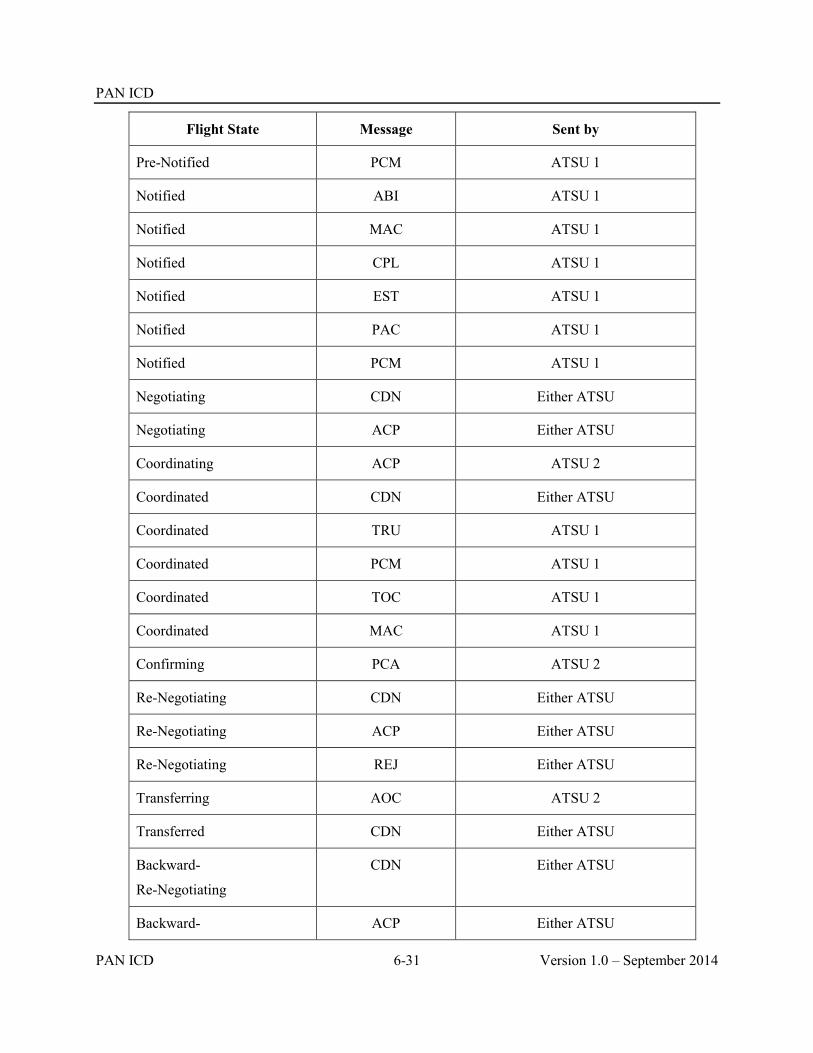
PAN ICD
PAN ICD 6-31 Version 1.0 – September 2014
Flight State Message Sent by
Pre-Notified PCM ATSU 1
Notified ABI ATSU 1
Notified MAC ATSU 1
Notified CPL ATSU 1
Notified EST ATSU 1
Notified PAC ATSU 1
Notified PCM ATSU 1
Negotiating CDN Either ATSU
Negotiating ACP Either ATSU
Coordinating ACP ATSU 2
Coordinated CDN Either ATSU
Coordinated TRU ATSU 1
Coordinated PCM ATSU 1
Coordinated TOC ATSU 1
Coordinated MAC ATSU 1
Confirming PCA ATSU 2
Re-Negotiating CDN Either ATSU
Re-Negotiating ACP Either ATSU
Re-Negotiating REJ Either ATSU
Transferring AOC ATSU 2
Transferred CDN Either ATSU
Backward-
Re-Negotiating
CDN Either ATSU
Backward- ACP Either ATSU

PAN ICD
Version 1.0 – September 2014 6-32 PAN ICD
Flight State Message Sent by
Re-Negotiating
Backward-
Re-Negotiating
REJ Either ATSU
6.5 Other AIDC messages
6.5.1 The previous sections have discussed the use of Notification, Coordination Confirmation and Transfer of Control messages. There are three additional AIDC message groups:
General Information messages;
Application management messages; and
Surveillance Data Transfer messages.
6.5.2 All AIDC messages within these three message groups require only an application response; no operational response is defined. No change to flight state occurs as a result of transmitting or receiving these AIDC messages.
6.5.3 General information messages.
6.5.3.1 EMG and MIS Messages.
6.5.3.2 These messages support the exchange of text information between ATSUs. A communicator (usually a person, but a computer or application process is also permitted) in one ATSU can send a free text message to a functional address at another ATSU. Typical functional addresses could be an area supervisor or an ATC sector. The EMG should have an AFTN emergency priority (SS).
6.5.4 Application Management messages.
6.5.4.1 Application management messages refer to Application responses (LAM and LRM) status monitoring (ASM), and FANS data link connection transfer (FAN and FCN) capabilities.
6.5.4.2 Because of their important role in the AIDC process, the LAM and LRM were described separately, earlier in this document (refer to Para 4.8).
6.5.4.3 Application Status Monitor (ASM)
6.5.4.3.1 The ASM message is used to confirm that the communication link between two ATS Units is on line, as well as confirming that the AIDC application of another ATS Unit is on-line. This message is sent by one ATSU to another if, after a mutually agreed time, no AIDC messages (including Application response messages - LAM or LRM) have been received from the other ATSU. An ATSU receiving an ASM message should respond with an appropriate application response.
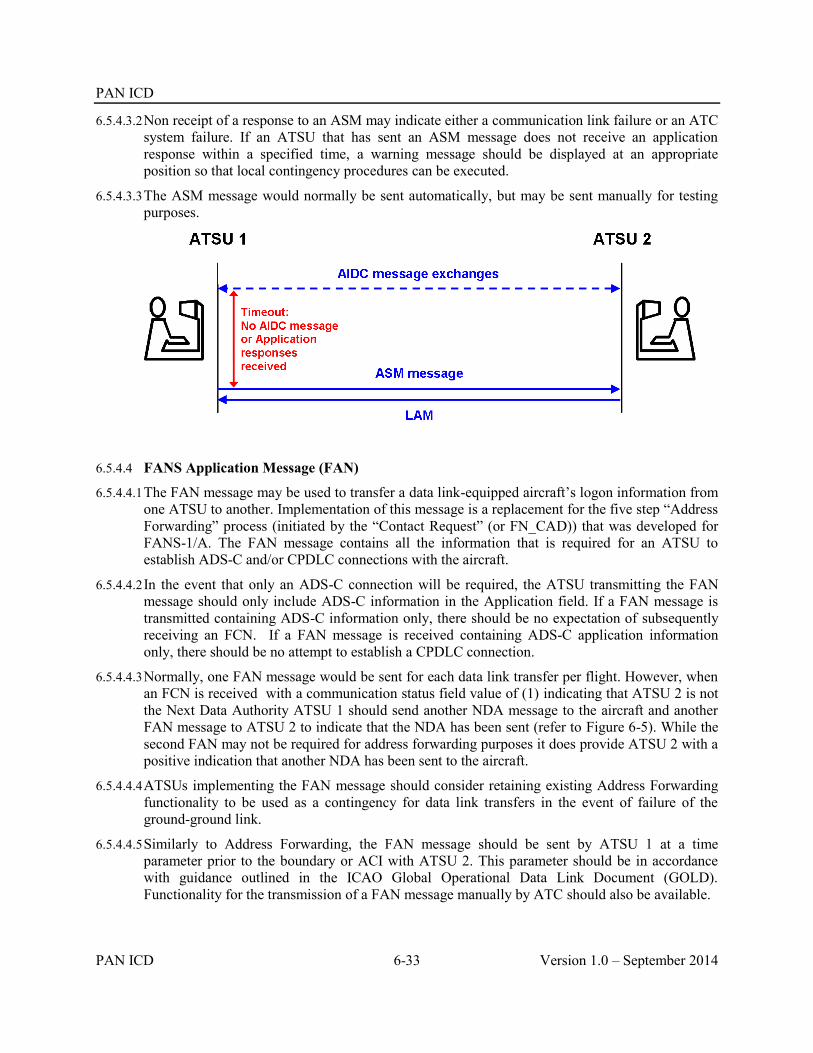
PAN ICD
PAN ICD 6-33 Version 1.0 – September 2014
6.5.4.3.2 Non receipt of a response to an ASM may indicate either a communication link failure or an ATC system failure. If an ATSU that has sent an ASM message does not receive an application response within a specified time, a warning message should be displayed at an appropriate position so that local contingency procedures can be executed.
6.5.4.3.3 The ASM message would normally be sent automatically, but may be sent manually for testing purposes.
6.5.4.4 FANS Application Message (FAN)
6.5.4.4.1 The FAN message may be used to transfer a data link-equipped aircraft’s logon information from one ATSU to another. Implementation of this message is a replacement for the five step “Address Forwarding” process (initiated by the “Contact Request” (or FN_CAD)) that was developed for FANS-1/A. The FAN message contains all the information that is required for an ATSU to establish ADS-C and/or CPDLC connections with the aircraft.
6.5.4.4.2 In the event that only an ADS-C connection will be required, the ATSU transmitting the FAN message should only include ADS-C information in the Application field. If a FAN message is transmitted containing ADS-C information only, there should be no expectation of subsequently receiving an FCN. If a FAN message is received containing ADS-C application information only, there should be no attempt to establish a CPDLC connection.
6.5.4.4.3 Normally, one FAN message would be sent for each data link transfer per flight. However, when an FCN is received with a communication status field value of (1) indicating that ATSU 2 is not the Next Data Authority ATSU 1 should send another NDA message to the aircraft and another FAN message to ATSU 2 to indicate that the NDA has been sent (refer to Figure 6-5). While the second FAN may not be required for address forwarding purposes it does provide ATSU 2 with a positive indication that another NDA has been sent to the aircraft.
6.5.4.4.4 ATSUs implementing the FAN message should consider retaining existing Address Forwarding functionality to be used as a contingency for data link transfers in the event of failure of the ground-ground link.
6.5.4.4.5 Similarly to Address Forwarding, the FAN message should be sent by ATSU 1 at a time parameter prior to the boundary or ACI with ATSU 2. This parameter should be in accordance with guidance outlined in the ICAO Global Operational Data Link Document (GOLD). Functionality for the transmission of a FAN message manually by ATC should also be available.

PAN ICD
Version 1.0 – September 2014 6-34 PAN ICD
6.5.4.4.6 Information concerning the identity of the aircraft (i.e. aircraft identification, aircraft address and registration) contained in the Application data field must not be extracted from the flight plan – it must be information that was contained in either the most recently received logon or FAN message.
Note. This requirement only applies to the aircraft identification within the Application data field of the FAN message. The aircraft identification (i.e. Field 7a) at the beginning of the FAN message is the identification of the aircraft from the ATS flight plan.
6.5.4.4.7 When extracting the aircraft identification from the logon, the information required is the aircraft identification within the CRC protected portion of the logon – not the flight identifier (FI) that is contained in Line 4 of the ACARS logon message. In the example below, the aircraft identification is QFA924 rather than the QF0924 contained in Line 4 of the ACARS message.
QU BNECAYA
.QXSXMXS 010019
AFD
FI QF0924/AN VH-EBA
DT QXT POR1 010019 J59A
- AFN/FMHQFA924,.VH-EBA,001902/FPOS33373E150484,0/FCOADS, 01/FCOATC,01292B
6.5.4.4.8 Under certain circumstances (e.g. FMC failure) it is possible for the SMI of an aircraft to change in flight, which will require a new logon from the aircraft to permit data link services to continue. To ensure that the next ATSU has up to date information, the SMI transmitted in any FAN message should be the SMI from the most recently received logon or FAN message.
6.5.4.4.9 A hyphen within the registration that was contained in either the logon or any previously received FAN message must also be included in the REG element of any transmitted FAN message. Without this hyphen, data link messages transmitted by the ATSU will not be delivered to the aircraft.
6.5.4.4.10 Any “padding” in the registration contained in the AFN logon (e.g. preceding periods “.”) must not be included in the FAN message. In the sample ACARS message above, the registration to be included in the FAN message would be “VH-EBA”, not “.VH-EBA”.
6.5.4.4.11 Some ATSUs may utilize the aircraft position which is an optional field that may be contained in the logon. If the aircraft position information element is to be included in any transmitted FAN message, the calculated position of the aircraft at the time of FAN transmission should be used. The aircraft position from the original logon should not be used for this purpose because this information will be out of date when the FAN message is transmitted.
6.5.4.5 FANS Completion Notification (FCN)
6.5.4.5.1 The FCN message, where used, provides advice to ATSU 1 concerning the CPDLC connection status of ATSU 2. The transmission of an FCN message is triggered by an event such as the termination of a CPDLC Connection by ATSU 1, or the establishment of (or failure to establish) an inactive CPDLC Connection by ATSU 2. FCN messages should only be transmitted when a CPDLC transfer is being effected – i.e. not for transfers involving aircraft that are only ADS-C

PAN ICD
PAN ICD 6-35 Version 1.0 – September 2014
equipped, or where a FAN message has been transmitted solely to permit an adjacent ATS Unit to establish ADS contracts with an aircraft.
6.5.4.6 Multiple FCN messages.
6.5.4.6.1 The general philosophy for use of the FCN is that only a single FCN message is transmitted by each ATSU for each flight. Under normal conditions, changes in CPDLC status after transmission of an FCN should not result in the transmission of another FCN (an exception to this is when a Connection request fails due to ATSU 2 not being the nominated next data authority – see Table 6-6 below).
Table 6-6. FCN Transmission
ATSU transmitting FCN When an FCN should be sent
ATSU 1 On receipt of a Disconnect Request terminating the CPDLC Connection (CPD=0)
ATSU 2 On receipt of a Connection Confirm, establishing a CPDLC Connection (CPD=2)
ATSU 2 On receipt of CPDLC downlink DM64 [ICAO facility designation] (CPD=1),
Note. This provides advice to ATSU 1 to uplink an appropriate Next Data Authority message to the aircraft.
And subsequently:
On establishment of a CPDLC Connection (CPD=2)
ATSU 2 At a time parameter prior to the FIR boundary, if no CPDLC Connection could be established (CPD=0)
6.5.4.6.2 Procedures following a change to CPDLC Connectivity, e.g., loss of the inactive CPDLC connection, following the transmission of an FCN message should be described in local procedures (e.g. voice coordination), rather than by transmission of another FCN message.
6.5.4.6.3 Non-receipt of an FCN (CPD = 0) by ATSU 2 should prompt ATSU 2 to ensure that they are the CPDLC current data authority for the aircraft.
6.5.4.6.4 Procedures for the notification of changes to the voice communication frequency after the transmission of an FCN message should be described in local procedures rather than via the transmission of another FCN message.
6.5.4.7 Sample flight threads involving FAN and FCN messages
6.5.4.7.1 The following diagrams show typical flight threads involving the FAN and FCN messages. Relevant uplink and downlink messages between the aircraft and the ATSU are also shown.

PAN ICD
Version 1.0 – September 2014 6-36 PAN ICD
Figure 6-2. Routine Data Link Transfer Using FAN and FCN Messaging
6.5.4.7.2 Figure 6-2 shows a routine CPDLC transfer from one ATSU to the next. The first step in the transfer process is the uplink of a CPDLC Next Data Authority message to the aircraft advising the avionics of the next centre that will be communicating with the aircraft via CPDLC. A FAN message is then sent to the next ATSU to provide them with the aircraft’s logon information. ATSU 2 then successfully establishes a CPDLC connection with the aircraft and transmits a ‘successful’ FCN (CPD = 2) to ATSU 1. On termination of the CPDLC connection, ATSU 1 transmits an FCN (CPD = 0) to ATSU 2 indicating that it has become the CPDLC current data authority.

PAN ICD
PAN ICD 6-37 Version 1.0 – September 2014
Figure 6-3 CPDLC Transfer Using FAN and FCN Messaging – Initial Connection Request Failed
6.5.4.7.3 Figure 6-3 shows a CPDLC transfer where there is no response by the avionics to the initial Connection Request uplinked by ATSU 2. A subsequent Connection Request is uplinked to the aircraft which is successful. Because the CPDLC connection is finally established before the ‘time out’ VSP prior to the FIR boundary, a successful FCN (CPD=2) is transmitted to ATSU 1. On termination of the CPDLC connection, ATSU 1 transmits an FCN (CPD=0) to ATSU 2.

PAN ICD
Version 1.0 – September 2014 6-38 PAN ICD
Figure 6-4 CPDLC Transfer Using FAN and FCN Messaging – Unable to Establish CPDLC Connection
6.5.4.7.4 Figure 6-4 shows an attempted CPDLC transfer where there is no response by the avionics to multiple CPDLC connection requests uplinked by ATSU 2 before the ‘time out’ VSP prior to the FIR boundary. An unsuccessful FCN (CPD=0) is transmitted to ATSU 1. Letters of Agreement should describe the procedures to be followed in the event that ATSU 2 establishes a CPDLC connection after this FCN has been transmitted. Even though ATSU 2 has advised of their inability to establish a CPDLC connection, ATSU 1 still transmits an FCN (CPD=0) when their CPDLC connection with the aircraft is terminated.

PAN ICD
PAN ICD 6-39 Version 1.0 – September 2014
Figure 6-5 CPDLC Transfer Using FAN and FCN Messaging – Initial NDA not Delivered
6.5.4.7.5 Figure 6-5 shows a CPDLC transfer in which the original Next Data Authority message uplinked by ATSU 1 is not delivered to the aircraft. An FCN (CPD=1) is transmitted by ATSU 2 advising of the failure of their CPDLC Connection request. Another Next Data Authority message is uplinked to the aircraft. ATSU 1 may send another FAN message after which ATSU 2 successfully establishes a CPDLC connection. Because this occurs before the time out VSP prior to the FIR boundary, a successful FCN (CPD=2) is transmitted back to ATSU 1. On termination of the CPDLC connection, ATSU 1 transmits an FCN (CPD=0) to ATSU 2.
6.5.5 Surveillance data transfer messages.
6.5.5.1 The ADS message is used to transfer data contained within an ADS-C report including optional ADS-C groups to an adjacent ATSU.
6.5.5.2 The ADS message contains a text field – the ADS-C data field – which contains information from the ADS-C report in its original hexadecimal format. The ADS-C data field consists of the text that immediately follows the “ADS” IMI (but excluding the 4 character CRC) within the application data portion of the ADS-C report.

PAN ICD
Version 1.0 – September 2014 6-40 PAN ICD
6.5.5.3 The following example shows an encoded ACARS ADS-C report – as it would be received by an ATSU – as well as an example of what information from this report would be transferred into the corresponding ADS-C data field. The ATSU receiving the AIDC ADS message simply decodes the ADS-C data field and extracts the data that is required by the ATSU.
ACARS ADS-C
report
QU BNECAYA
.QXSXMXS 011505
PAR
FI NZ0090/AN ZK-OKC
DT QXT POR1 011505 F59A
- ADS.ZK-OKC030007FF946B6F6DC8FC044B9D0DFC013B80DA88FCOA64F9E4438B4AC8FC000E34D0EDC00010140F3E8660F3
ADS-C data field
ADS/.ZK-OKC030007FF946B6F6DC8FC044B9D0DFC013B80DA88FC0A64F9E4438B4AC8FC000E34D0EDC00010140F3E86
Note. Because it is part of the 7 character registration field the leading “.” in front of the registration in the ACARS message (“.ZK-OKC”) must be retained. The 4 character CRC (“60F3”) at the end of the ACARS ADS-C report is not included in the ADS-C data field.
6.5.5.4 The types of ADS-C reports (i.e. periodic or event) transmitted in the AIDC ADS message should be in accordance with bilateral agreements. When implementing the AIDC ADS message, ATSUs should consider the effect of relaying numerous ADS-C periodic reports via ground-ground links (e.g. AFTN) when a high periodic reporting rate is in effect.
6.5.5.5 The AIDC ADS message is used to transfer ADS-C information only. Other messaging protocols exist for the transfer of ADS-B and other types of surveillance information.
6.5.5.6 While the AIDC ADS message may be used to transfer ADS-C information, this data may also be transferred using the ACARS ground-ground network by re-addressing the received ADS-C message to the other ATSU. States should agree on the method to be used on a bilateral basis.
Example: Brisbane ATSU (BNECAYA) receives an ADS-C downlink via the ACARS network from its Data link Service Provider SITA (QXSXMXS)
QU BNECAYA
QXSXMXS 011505
PAR
FI NZ0090/AN ZK-OKC
DT QXT POR1 011505 F59A
- ADS.ZK-OKC0300FF946B6F6DC8FC044B9D0DFC013B80DA88FC0A64F9E4438B4AC8FC000E34D0EDC00010140F3EE8660F3
Brisbane re-addresses the downlink and forwards to Auckland via the ACARS ground-ground network:

PAN ICD
PAN ICD 6-41 Version 1.0 – September 2014
QU AKLCBYA
.BNECAYA 011505
PAR
FI NZ0090/AN ZK-OKC
DT QXT POR1 011505 F59A
- ADS.ZK-OKC0300FF946B6F6DC8FC044B9D0DFC013B80DA88FC0A64F9E4438B4AC8FC000E34D0EDC00010140F3EE8660F3

PAN ICD
Version 1.0 – September 2014 6-42 PAN ICD
6.6 Examples
6.6.1 The following section contains a number of examples illustrating how the AIDC message set may be used operationally. These examples are illustrative only – they do not necessarily reflect the AIDC messages that might actually be used in the circumstances, nor the actual airspace coordination requirements.
6.6.2 The specific AIDC messages to be used and the timing of the transmission of these messages are defined in bilateral agreements between the relevant ATS Units.
6.6.3 In the following examples, unless otherwise stated, the AIDC messages are transmitted at a specified time or position prior to the FIR or ACI boundary. Depending on the AIDC message received, Operational responses might be transmitted either automatically or manually.
6.6.4 Each of the following examples consists of:
A text description;
A flight thread that graphically illustrates the sequence of messages. For ease of reference, these flight threads are color coded, with message dialogues displayed in the same color. AIDC messages not related to Notification, Coordination or Transfer of Control, are shown as a dashed line;
A table containing the associated AIDC messages.
For simplification, the examples do not include Application Management (LAM/LRM) messages.
6.6.4.1 Example 1 – Coordination using abbreviated initial coordination dialogue
6.6.4.1.1 ATSU 1transmits a notification message (ABI) to ATSU 2. The ABI contains Estimate data of RUNOD at 1209, operating in a block clearance between FL350 and FL370. By agreement, ATSU 1 includes flight planned speed/level changes in Field 15 of AIDC messages. Subsequently the estimate for RUNOD changes to 1213, but ATSU 1 has an agreement with ATSU 2 not to send revised Notification messages for revisions of less than 5 minutes.
6.6.4.1.2 ATSU 1 transmits an abbreviated coordination message (EST) to ATSU 2. The proposed coordination contains Estimate data of RUNOD at 1213 operating in a block clearance between FL350 and FL370. ATSU 2 accepts the proposed coordination conditions by responding with an ACP.
6.6.4.1.3 ATSU 1 proposes a transfer of control responsibility by transmitting a TOC to ATSU 2. ATSU 2 accepts control responsibility by responding with an AOC.

PAN ICD
PAN ICD 6-43 Version 1.0 – September 2014
ATSU 1 (ABI-ANZ804/A1207-YBBN-RUNOD/1209F350F370-NZCH-8/IS-9/A320/M-10/SDE1E3FGHIM2RW/LB1-15/N0448F370 2719S15313E SCOTT Y76 SIFRA/M078F390 L503 CH DCT-18/PBN/A1C1D1O1S2T1 REG/ZKOJK EET/NZZO0132 SEL/HJRS CODE/C81845 OPR/ANZ RALT/NZAA YBCG YSSY RMK/TCAS EQUIPPED)
ATSU 1 (EST-ANZ804/A1207-YBBN-RUNOD/1213F350F370-NZCH)
ATSU 2 (ACP-ANZ804/A1207-YBBN-NZCH)
ATSU 1 (TOC-ANZ804/A1207-YBBN-NZCH)
ATSU 2 (AOC-ANZ804/A1207-YBBN-NZCH)
6.6.4.2 Example 2 – Coordination using initial coordination dialogue
6.6.4.2.1 ATSU 1 transmits a notification message (ABI) to ATSU 2. The ABI contains Estimate data of 6852N06414W at 1503 climbing from F350 to F370, and with a weather deviation clearance up to 20NM to the right of route.
6.6.4.2.2 ATSU 1 transmits a coordination message (CPL) to ATSU 2. The proposed coordination contains Estimate data of 6852N06414W at 1505 climbing from F350 to F370, and with a weather deviation clearance up to 20NM to the right of route. ATSU 2 accepts the proposed coordination without modification by responding with an ACP.
6.6.4.2.3 ATSU 1 proposes a transfer of control responsibility by transmitting a TOC to ATSU 2. ATSU 2 accepts control responsibility by responding with an AOC

PAN ICD
Version 1.0 – September 2014 6-44 PAN ICD
ATSU 1 (ABI-ICE680-KSEA-6852N06414W/1503F370F350A/W20R-BIKF-8/IS-9/B752/M-10/SWXRGIDFHY/LB1-15/M079F370 6852N06414W BOPUT 6900N06000W 6900N05000W 6800N04000W 6600N03000W HEKLA-18/PBN/A1B2B3B4B5D1L1S1 NAV/RNVD1A1 DOF/131124 REG/TFLLX EET/CZVR0019 CZEG0049 BGGL0450 BIRD0621 SEL/DSHK OPR/ICE RALT/CYEG BGSF RMK/ADSB)
ATSU 1 (CPL-ICE680-IS-B752/M-SWXRGIDFHY/LB1-KSEA-6852N06414W/1505F370F350A/W20R-M079F370 6852N06414W BOPUT 6900N06000W 6900N05000W 6800N04000W 6600N03000W HEKLA-BIKF-PBN/A1B2B3B4B5D1L1S1 NAV/RNVD1A1 DOF/131124 REG/TFLLX EET/CZVR0019 CZEG0049 BGGL0450 BIRD0621 SEL/DSHK OPR/ICE RALT/CYEG BGSF RMK/ADSB)
ATSU 2 (ACP-ICE680-KSEA-BIKF)
ATSU 1 (TOC-ICE680-KSEA-BIKF)
ATSU 2 (AOC-ICE680-KSEA-BIKF)
6.6.4.3 Example 3 – Negotiation of proposed coordination, and CPDLC transfer
6.6.4.3.1 ATSU 1 transmits a notification message (ABI) to ATSU 2. The ABI contains Estimate data of 3010S16300E at 2325 at F370.
6.6.4.3.2 ATSU 1 transmits a coordination message (CPL) to ATSU 2. The proposed coordination contains Estimate data of 3010S16300E at 2324 at F370
6.6.4.3.3 ATSU 2 responds by transmitting a negotiation message (CDN) to ATSU 1 proposing (or requesting) an amendment to the proposed coordination to F390. ATSU 2 accepts the revised coordination by responding with ACP. The agreed coordination is now 3010S16300E at 2324 at F390.
6.6.4.3.4 ATSU 1 transmits a FAN message to ATSU 2 providing the logon information that ATSU 2 requires to establish a CPDLC connection as well as ADS contracts.
6.6.4.3.5 When an inactive CPDLC connection is established, ATSU 2 transmits an FCN to ATSU 1, including the appropriate HF frequency for the aircraft to monitor.

PAN ICD
PAN ICD 6-45 Version 1.0 – September 2014
6.6.4.3.6 ATSU 1 proposes a transfer of control responsibility by transmitting a TOC to ATSU 2. ATSU 2 accepts control responsibility by responding with an AOC.
6.6.4.3.7 ATSU 1 terminates the CPDLC connection and transmits an FCN to ATSU 2 notifying them that the CPDLC connection has been terminated.
ATSU 1 (ABI-ANZ764-YSSY-3010S16300E/2325F370-YSNF-8/IS-9/A320/M-10/SDE1E3FGHIJ3J5M2RW/LB1D1-15/M078F370 SY B450 LHI 3010S16300E NF DCT-18/PBN/A1C1D1O1S2T1 REG/ZKOJK EET/NZZO0131 SEL/HJRS CODE/C81845 OPR/ANZ RMK/TCAS EQUIPPED)
ATSU 1 (CPL-ANZ764-IS-A320/M-SDE1E3FGHIJ3J5M2RW/LB1D1-YSSY-3010S16300E/2324F370-M078F370 SY B450 LHI 3010S16300E NF DCT-YSNF-PBN/A1C1D1O1S2T1 REG/ZKOJK EET/NZZO0131 SEL/HJRS CODE/C81845 OPR/ANZ RMK/TCAS EQUIPPED)
ATSU 2 (CDN-ANZ764-YSSY-YSNF-14/3010S16300E/2324F390)
ATSU 1 (ACP-ANZ764-YSSY-YSNF)
ATSU 1 (FAN-ANZ764-YSSY-YSNF-SMI/AFD FMH/ANZ764 REG/ZK-OJK FPO/3108S16013E FCO/ATC01 FCO/ADS01)
ATSU 2 (FCN-ANZ764-YSSY-YSNF-CPD/2 FREQ/13261)
ATSU 1 (TOC-ANZ764-YSSY-YSNF)
ATSU 2 (AOC-ANZ764-YSSY-YSNF)
ATSU 1 (FCN-ANZ764-YSSY-YSNF-CPD/0)

PAN ICD
Version 1.0 – September 2014 6-46 PAN ICD
6.6.4.4 Example 4 – Multiple notifications, automatic coordination updates and coordination confirmation
6.6.4.4.1 ATSU 1 transmits a notification message (ABI) to ATSU 2. The ABI contains Estimate data of 65N040W at 0405 at F350. The route in the ABI (and subsequent AIDC messages) is truncated (“T”) due to a duplicated waypoint in the flight planned route.
6.6.4.4.2 Following the issuing of a cruise climb and weather deviation clearance, ATSU 1 transmits an additional notification message (ABI) to ATSU 2. The ABI now contains Estimate data of 65N040W at 0406 cruise climbing from F350 to F370, and with a weather deviation clearance up to 30NM either side of route.
6.6.4.4.3 ATSU 1 transmits a coordination message (CPL) to ATSU 2. The proposed coordination contains Estimate data of 65N040W at 0407 at F370F350C, and with a weather deviation clearance up to 30NM either side of route. ATSU 2 accepts the proposed coordination without modification by responding with an ACP.
6.6.4.4.4 ATSU 1 transmits a TRU message to ATSU 2, providing a coordination update that the aircraft is now cleared in a weather deviation up to 40NM either side of route.
6.6.4.4.5 ATSU 1 transmits a PCM to ATSU 2 to confirm that the coordination held by ATSU 2 is correct. ATSU 2 confirms that their coordination is up to date by responding with a PCA.
6.6.4.4.6 ATSU 1 proposes a transfer of control responsibility by transmitting a TOC to ATSU 2. ATSU 2 accepts control responsibility by responding with an AOC
ATSU 1 (ABI-MSR995/A3057-HECA-65N040W/0405F350-CYYZ-8/IS-9/B77W/H-10/SDE1E2E3FGHIJ2J3J4J5M1RWXYZ/LB1D1-15/M084F350 65N040W 63N050W 60N060W LAKES T-18/PBN/A1B1C1D1 NAV/RNVD1E2A1 RNP5 DAT/SVH DOF/131124 REG/SUGDM EET/LCCC0029 LTAA0051 LTBB0115 SEL/FSDP OPR/EGYPTAIR RALT/EGPK CYYR RMK/TCAS)
ATSU 1 (ABI-MSR995/A3057-HECA-65N040W/0406F370F350C/W30E-CYYZ-8/IS-9/B77W/H-10/SDE1E2E3FGHIJ2J3J4J5M1RWXYZ/LB1D1-15/M084F350 65N040W

PAN ICD
PAN ICD 6-47 Version 1.0 – September 2014
63N050W 60N060W LAKES T-18/PBN/A1B1C1D1 NAV/RNVD1E2A1 RNP5 DAT/SVH DOF/131124 REG/SUGDM EET/LCCC0029 LTAA0051 LTBB0115 SEL/FSDP OPR/EGYPTAIR RALT/EGPK CYYR RMK/TCAS)
ATSU 1 (CPL-MSR995/A3057-IS-B77W/H-SDE1E2E3FGHIJ2J3J4J5M1RWXYZ/LB1D1-HECA-65N040W/0407F370F350C/W30E-M084F370 65N040W 63N050W 60N060W LAKES T-CYYZ-PBN/A1B1C1D1 NAV/RNVD1E2A1 RNP5 DAT/SVH DOF/131124 REG/SUGDM EET/LCCC0029 LTAA0051 LTBB0115 SEL/FSDP OPR/EGYPTAIR RALT/EGPK CYYR RMK/TCAS)
ATSU 2 (ACP-MSR995/A3057-HECA-CYYZ)
ATSU 1 (TRU-MSR995/A3057-HECA-CYYZ-OTD/W40E)
ATSU 1 (PCM-MSR995/A3057-HECA-65N040W/0407F370F350C/W40E-CYYZ-8/IS-9/B77W/H-10/SDE1E2E3FGHIJ2J3J4J5M1RWXYZ/LB1D1-15/M084F370 65N040W 63N050W 60N060W LAKES T-18/PBN/A1B1C1D1 NAV/RNVD1E2A1 RNP5 DAT/SVH DOF/131124 REG/SUGDM EET/LCCC0029 LTAA0051 LTBB0115 SEL/FSDP OPR/EGYPTAIR RALT/EGPK CYYR RMK/TCAS)
ATSU 2 (PCA-MSR995/A3057-HECA-CYYZ)
ATSU 1 (TOC-MSR995/A3057-HECA-CYYZ)
ATSU 2 (AOC-MSR995/A3057-HECA-CYYZ)
6.6.4.5 Example 5 – Coordination re-negotiation and automatic coordination updates
6.6.4.5.1 ATSU 1 transmits a notification message (ABI) to ATSU 2. The ABI contains Estimate data of ESKEL at 0245 at F350.
6.6.4.5.2 ATSU 1 transmits an abbreviated coordination message (EST) to ATSU 2.The proposed coordination contains Estimate data of ESKEL at 0245 at F350. ATSU 2 accepts the proposed coordination conditions by responding with an ACP.
6.6.4.5.3 After coordination has been completed, but prior to the transfer of control ATSU 2 proposes (or requests) an amendment to the proposed coordination to F390 by transmitting a negotiation message (CDN) to ATSU 1 The proposed amendment is not acceptable to ATSU 1, and the proposal is rejected by the transmitting of an REJ response to ATSU 2.
6.6.4.5.4 ATSU 1 transmits a TRU message to ATSU 2, providing a coordination update that the aircraft has been cleared to deviate up to 20NM left of route. The TRU also provides advice that the aircraft is requesting F370. The requested level was not proposed by a negotiation message (CDN), because the requested level was not available in ATSU 1’s airspace.
6.6.4.5.5 ATSU 1 proposes a transfer of control responsibility by transmitting a TOC to ATSU 2. ATSU 2 accepts control responsibility by responding with an AOC.

PAN ICD
Version 1.0 – September 2014 6-48 PAN ICD
ATSU 1 (ABI-QFA143/A1540-YSSY-ESKEL/0245F350-NZAA-8/IS-9/B738/M-10/SDE2E3FGHIRWYZ/LB1-15/N0448F350 EVONN L521 AA DCT-18/PBN/A1S1T1 NAV/GPSRNAV DOF/140117 REG/ZKZQC EET/YBBB0008 NZZO0121 SEL/ESAP CODE/C81CF8 PER/C)
ATSU 1 (EST-QFA143/A1540-YSSY-ESKEL/0245F350-NZAA)
ATSU 2 (ACP-QFA143/A1540-YSSY-NZAA)
ATSU 2 (CDN-QFA143/A1540-YSSY-NZAA-14/ESKEL/0245F390)
ATSU 1 (REJ-QFA143/A1540-YSSY-NZAA)
ATSU 1 (TRU-QFA143/A1540-YSSY-NZAA-RFL/F370 OTD/W20L)
ATSU 1 (TOC-QFA143/A1540-YSSY-NZAA)
ATSU 2 (AOC-QFA143/A1540-YSSY-NZAA)
6.6.4.6 Example 6 – Coordination re-negotiation, automatic coordination updates and coordination confirmation
6.6.4.6.1 ATSU 1 transmits a notification message (ABI) to ATSU 2. The ABI contains Estimate data of 65N040W at 1145, operating in a block clearance F350 to F370. The route in the ABI (and subsequent AIDC messages) is truncated (“T”) due to a duplicated waypoint in the flight planned route.
6.6.4.6.2 ATSU 1 transmits a coordination message (CPL) to ATSU 2. The proposed coordination contains Estimate data of 65N040W at 1146, operating in a block clearance F350 to F370. ATSU 2 accepts the proposed coordination without modification by responding with an ACP.
6.6.4.6.3 After coordination has been completed, but prior to the transfer of control, ATSU 1 proposes an amendment to the proposed coordination to block clearance F370 to F390 (climbing from
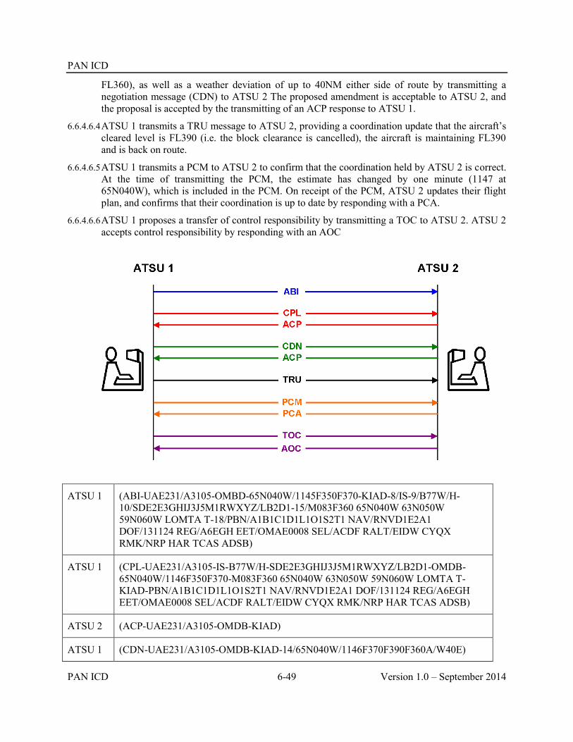
PAN ICD
PAN ICD 6-49 Version 1.0 – September 2014
FL360), as well as a weather deviation of up to 40NM either side of route by transmitting a negotiation message (CDN) to ATSU 2 The proposed amendment is acceptable to ATSU 2, and the proposal is accepted by the transmitting of an ACP response to ATSU 1.
6.6.4.6.4 ATSU 1 transmits a TRU message to ATSU 2, providing a coordination update that the aircraft’s cleared level is FL390 (i.e. the block clearance is cancelled), the aircraft is maintaining FL390 and is back on route.
6.6.4.6.5 ATSU 1 transmits a PCM to ATSU 2 to confirm that the coordination held by ATSU 2 is correct. At the time of transmitting the PCM, the estimate has changed by one minute (1147 at 65N040W), which is included in the PCM. On receipt of the PCM, ATSU 2 updates their flight plan, and confirms that their coordination is up to date by responding with a PCA.
6.6.4.6.6 ATSU 1 proposes a transfer of control responsibility by transmitting a TOC to ATSU 2. ATSU 2 accepts control responsibility by responding with an AOC
ATSU 1 (ABI-UAE231/A3105-OMBD-65N040W/1145F350F370-KIAD-8/IS-9/B77W/H-10/SDE2E3GHIJ3J5M1RWXYZ/LB2D1-15/M083F360 65N040W 63N050W 59N060W LOMTA T-18/PBN/A1B1C1D1L1O1S2T1 NAV/RNVD1E2A1 DOF/131124 REG/A6EGH EET/OMAE0008 SEL/ACDF RALT/EIDW CYQX RMK/NRP HAR TCAS ADSB)
ATSU 1 (CPL-UAE231/A3105-IS-B77W/H-SDE2E3GHIJ3J5M1RWXYZ/LB2D1-OMDB-65N040W/1146F350F370-M083F360 65N040W 63N050W 59N060W LOMTA T-KIAD-PBN/A1B1C1D1L1O1S2T1 NAV/RNVD1E2A1 DOF/131124 REG/A6EGH EET/OMAE0008 SEL/ACDF RALT/EIDW CYQX RMK/NRP HAR TCAS ADSB)
ATSU 2 (ACP-UAE231/A3105-OMDB-KIAD)
ATSU 1 (CDN-UAE231/A3105-OMDB-KIAD-14/65N040W/1146F370F390F360A/W40E)

PAN ICD
Version 1.0 – September 2014 6-50 PAN ICD
ATSU 2 (ACP-UAE231/A3105-OMDB-KIAD)
ATSU 1 (TRU-UAE231/A3105-OMDB-KIAD-PRL/F390 CFL/F390 OTD/0)
ATSU 1 (PCM-UAE231/A3105-OMBD-65N040W/1147F390-KIAD-8/IS-9/B77W/H-10/SDE2E3GHIJ3J5M1RWXYZ/LB2D1-15/M083F390 65N040W 63N050W 59N060W LOMTA T-18/PBN/A1B1C1D1L1O1S2T1 NAV/RNVD1E2A1 DOF/131124 REG/A6EGH EET/OMAE0008 SEL/ACDF RALT/EIDW CYQX RMK/NRP HAR TCAS ADSB)
ATSU 2 (PCA-UAE231/A3105-OMDB-KIAD)
ATSU 1 (TOC-UAE231/A3105-OMDB-KIAD)
ATSU 2 (AOC-UAE231/A3105-OMDB-KIAD)
6.6.4.7 Example 7 – Coordination from nearby aerodrome using abbreviated initial coordination dialogue, coordination re-negotiation and coordination confirmation
6.6.4.7.1 Several minutes before departure time (e.g. at taxi time), ATSU 1 transmits an abbreviated coordination message (PAC) to ATSU 2. The proposed coordination contains Estimate data of EGATU at 1213 at FL290. ATSU 2 accepts the proposed coordination conditions by responding with an ACP. The coordination prior to departure is required due to the proximity of the departure aerodrome to the FIR or ACI boundary.
6.6.4.7.2 On departure, the aircraft’s actual estimate differs from that previously coordinated by more than the value specified in bilateral agreements. ATSU 1 proposes an amendment to the estimate to 1219 by transmitting a negotiation message (CDN) to ATSU 2 The proposed amendment is acceptable to ATSU 2, and the proposal is accepted by the transmitting of an ACP response to ATSU 1
6.6.4.7.3 ATSU 1 transmits a PCM to ATSU 2 to confirm that the coordination held by ATSU 2 is correct. ATSU 2 confirms that their coordination is up to date by responding with a PCA.
6.6.4.7.4 ATSU 1 proposes a transfer of control responsibility by transmitting a TOC to ATSU 2. ATSU 2 accepts control responsibility by responding with an AOC.
6.6.4.7.5 After the transfer of control has occurred, but while the aircraft is still within the ACI associated with ATSU 1, the aircraft requests FL330. ATSU 2 proposes an amendment to the coordination held by ATSU 1 to F330 (climbing from FL290) by transmitting a negotiation message (CDN) to ATSU 1. The Estimate data in the CDN reflects the time that the aircraft actually crossed EGATO (1220). The proposed amendment is acceptable to ATSU 1, and the proposal is accepted by the transmitting of an ACP response to ATSU 2

PAN ICD
PAN ICD 6-51 Version 1.0 – September 2014
ATSU 1 (PAC-GIA726/A1351-WADD-EGATU/1213F290-YPPH-8/IS-9/B738/M-10/SDE2E3FGHIJ2ZRWY/LB1-15/N0464F290 MURAI2B DCT LIPRA/M078F330 G578 EGATU/N0466F330 L514 MUNNI/N0463F320 L514 REVOP Q67 JULIM DCT-18/PBN/A1D1 NAV/AUSEP DOF/140117 REG/PKGFU EET/YBBB0039 YMMM0104 SEL/AKMQ OPR/GARUDA PER/C RMK/TCAS EQUIPPED)
ATSU 2 (ACP-GIA726/A1351-WADD-YPPH)
ATSU 1 (CDN-GIA726/A1351-WADD-YPPH-14/EGATU/1219F290)
ATSU 2 (ACP-GIA726/A1351-WADD-YPPH)
ATSU 1 (PCM-GIA726/A1351-WADD-EGATU/1219F290-YPPH-8/IS-9/B738/M-10/SDE2E3FGHIJ2ZRWY/LB1-15/N0464F310 MURAI2B DCT LIPRA/M078F330 G578 EGATU/N0466F330 L514 MUNNI/N0463F320 L514 REVOP Q67 JULIM DCT-18/PBN/A1D1 NAV/AUSEP DOF/140117 REG/PKGFU EET/YBBB0039 YMMM0104 SEL/AKMQ OPR/GARUDA PER/C RMK/TCAS EQUIPPED)
ATSU 2 (PCA-GIA726/A1351-WADD-YPPH)
ATSU 1 (TOC-GIA726/A1351-WADD-YPPH)
ATSU 2 (AOC-GIA726/A1351-WADD-YPPH)
ATSU 2 (CDN-GIA726/A1351-WADD-YPPH-14/EGATU/1220F330F290A)
ATSU 1 (ACP-GIA726/A1351-WADD-YPPH)

PAN ICD
Version 1.0 – September 2014 6-52 PAN ICD
6.6.4.8 Example 8 – Multiple notification, coordination cancellation, and use of the ASM
6.6.4.8.1 ATSU 1 transmits a notification message (ABI) to ATSU 2. The ABI contains Estimate data of 29S163E at 1105 at FL290
6.6.4.8.2 Prior to coordination, a modification to the cleared flight level is made resulting in the transmission of another notification message to ATSU 2. The ABI contains Estimate data of 29S163E at 1107 at FL310.
6.6.4.8.3 ATSU 1 has not received any AIDC or application management messages from ATSU 3 for a system parameter, and so an ASM is transmitted to ATSU 3.
6.6.4.8.4 ATSU 1 transmits an abbreviated coordination message (EST) to ATSU 2. The proposed coordination contains Estimate data of 29S163E at 1108 at FL310. ATSU 2 accepts the proposed coordination conditions by responding with an ACP.
6.6.4.8.5 Due to weather the aircraft requests and is issued an amended route clearance that will now no longer affect ATSU 2. To cancel any notification and/or coordination, ATSU 1 transmits a MAC message to ATSU 2.
ATSU 1 (ABI-QFA11-YSSY-29S163E/1105F290-NFFN-8/IS-9/B744/H-10/SADE2E3FGHIJ2J4J5M1RWYZ/LB1D1-15/M081F290 DCT NOBAR B450 ABARB 29S163E 26S170E NILAX VIPOB MI-18/PBN/A1B1C1D1L1O1S2 NAV/GPSRNAV RNVD1A1 DOF/140117 REG/VHOQF EET/YBBB0009 NFFF0123 SEL/DLHS CODE/7C4925)
ATSU 1 (ABI-QFA11-YSSY-29S163E/1107F310-NFFN-8/IS-9/B744/H-10/SADE2E3FGHIJ2J4J5M1RWYZ/LB1D1-15/M081F350 DCT NOBAR B450 ABARB 29S163E 26S170E NILAX VIPOB MI-18/PBN/A1B1C1D1L1O1S2 NAV/GPSRNAV RNVD1A1 DOF/140117 REG/VHOQF EET/YBBB0009 NFFF0123 SEL/DLHS CODE/7C4925)
ATSU 1 (ASM)
ATSU 1 (EST-QFA11-YSSY-29S163E/1108F310-NFFN)
ATSU 2 (ACP-QFA11-YSSY-NFFN)
ATSU 1 (MAC-QFA11-YSSY-NFFN)

PAN ICD
PAN ICD 6-53 Version 1.0 – September 2014
6.6.4.9 Example 9 – CPDLC connection failure, multiple coordination re-negotiation, coordination confirmation
6.6.4.9.1 ATSU 1 transmits a notification message (ABI) to ATSU 2. The ABI contains Estimate data of OMKIN at 1209 at FL350, assigned M081 or greater.
6.6.4.9.2 ATSU 1 transmits an abbreviated coordination message (EST) to ATSU 2. The proposed coordination contains Estimate data of OMKIN at 1211 at FL350, assigned M081 or greater. ATSU 2 accepts the proposed coordination conditions by responding with an ACP.
6.6.4.9.3 ATSU 1 transmits a FAN message to ATSU 2 providing the logon information that ATSU 2 requires to establish a CPDLC connection as well as ADS contracts.
6.6.4.9.4 ATSU 2 is unable to establish an inactive CPDLC connection because they are not the nominated CPDLC “next data authority” and transmits an FCN message to ATSU 2 notifying them of this. Note. The non-receipt of an NDA message by the avionics could be because either the NDA message was not sent, or it was not delivered successfully to the aircraft.
6.6.4.9.5 ATSU 1 transmits an appropriate CPDLC Next data Authority message to the aircraft. ATSU 1 then transmits another FAN message to ATSU 2 providing the logon information that ATSU 2 requires to establish a CPDLC connection as well as ADS contracts. While this FAN message is technically not required, it provides information to ATSU 2 that an NDA message has been sent to the aircraft.
6.6.4.9.6 When an inactive CPDLC connection is established, ATSU 2 transmits an FCN to ATSU 1
6.6.4.9.7 After coordination has been completed, but prior to the transfer of control, ATSU 1 proposes an amendment to the proposed coordination to F370 (cancelling the speed restriction) by transmitting a negotiation message (CDN) to ATSU 2. The CDN also contains a revised estimate of 1213 at OMKIN. The proposed amendment is not acceptable to ATSU 2, but an alternative level (FL360, without speed restriction) is available. ATSU 2 therefore proposes an amendment to the original CDN by responding with a negotiation message (CDN) to ATSU 1. The proposed amendment is acceptable to ATSU 1, and the proposal is accepted by the transmitting of an ACP response to ATSU 2.
6.6.4.9.8 ATSU 1 transmits a PCM to ATSU 2 to confirm that the coordination held by ATSU 2 is correct. ATSU 2 confirms that their coordination is up to date by responding with a PCA.
6.6.4.9.9 ATSU 1 proposes a transfer of control responsibility by transmitting a TOC to ATSU 2. ATSU 2 accepts control responsibility by responding with an AOC.
6.6.4.9.10 ATSU 1 terminates the CPDLC connection and transmits an FCN to ATSU 2 notifying them that the CPDLC connection has been terminated.
6.6.4.9.11 ATS Units implementing CDN messaging should be aware that multiple complex negotiation dialogues may be more easily solved using voice communication.

PAN ICD
Version 1.0 – September 2014 6-54 PAN ICD
ATSU 1 (ABI-QFA121/A1475-YSSY-OMKIN/1209F350/GM081-NZQN-8/IS-9/B738/M-10/SADE2E3GHIJ3J5RWYZ/LB1D1-15/M081F350 OPTIC Y84 TONIM P766 ADKOS P753 QN DCT-18/PBN/A1B1C1D1O2S2T1 NAV/RNP2 GPSRNAV DOF/140118 REG/VHXZI EET/YBBB0008 NZZO0139 SEL/LMDP CODE/7C77FC OPR/QANTAS ORGN/YSSYQFAO PER/C)
ATSU 1 (EST-QFA121/A1475-YSSY-OMKIN/1211F350/GM081-NZQN)
ATSU 2 (ACP-QFA121/A1475-YSSY-NZQN)
ATSU 1 (FAN-QFA121/A1475-YSSY-NZQN-SMI/AFD FMH/QFA121 REG/VH-XZI FPO/4053S16042E FCO/ATC01 FCO/ADS01)
ATSU 2 (FCN-QFA121/A1475-YSSY-NZQN-CPD/1)
ATSU 1 (FAN-QFA121/A1475-YSSY-NZQN-SMI/AFD FMH/QFA121 REG/VH-XZI FPO/4102S16054E FCO/ATC01 FCO/ADS01)
ATSU 2 (FCN-QFA121/A1475-YSSY-NZQN-CPD/2)
ATSU 1 (CDN-QFA121/A1475-YSSY-NZQN-14/OMKIN/1213F370)
ATSU 2 (CDN-QFA121/A1475-YSSY-NZQN-14/OMKIN/1213F360)

PAN ICD
PAN ICD 6-55 Version 1.0 – September 2014
ATSU 1 (ACP-QFA121/A1475-YSSY-NZQN)
ATSU 1 (PCM-QFA121/A1475-YSSY-OMKIN/1213F360-NZQN-8/IS-9/B738/M-10/SADE2E3GHIJ3J5RWYZ/LB1D1-15/N0442F360 OPTIC Y84 TONIM P766 ADKOS P753 QN DCT-18/PBN/A1B1C1D1O2S2T1 NAV/RNP2 GPSRNAV DOF/140118 REG/VHXZI EET/YBBB0008 NZZO0139 SEL/LMDP CODE/7C77FC OPR/QANTAS ORGN/YSSYQFAO PER/C))
ATSU 2 (PCA-QFA121/A1475-YSSY-NZQN)
ATSU 1 (TOC-QFA121/A1475-YSSY-NZQN)
ATSU 2 (AOC-QFA121/A1475-YSSY-NZQN)
ATSU 1 (FCN-QFA121/A1475-YSSY-NZQN-CPD/0)
6.6.4.10 Example 10 – Coordination re-negotiation of a revised destination, CPDLC transfer, infringing an adjacent ACI and use of the ADS message
6.6.4.10.1 ATSU 1 transmits a notification message (ABI) to ATSU 2. The ABI contains Estimate data of RUNOD at 0006 at F370.
6.6.4.10.2 ATSU 1 transmits an abbreviated coordination message (EST) to ATSU 2. The proposed coordination contains Estimate data of RUNOD at 0007 at FL370. ATSU 2 accepts the proposed coordination conditions by responding with an ACP.
6.6.4.10.3 After the coordination has been completed, but prior to the transfer of control, the aircraft requests a diversion to a new destination aerodrome (NZAA), which also involves an amended route and estimate data. ATSU 1 proposes an amendment to the proposed coordination by transmitting a negotiation message (CDN) to ATSU 2. The CDN contains new Estimate data of VEPAS at 2357 at FL370. ATSU 2 accepts the revised coordination by responding with ACP (which contains the original destination – NZCH). All subsequent AIDC messages for this aircraft contain “NZAA” as the destination aerodrome.
6.6.4.10.4 ATSU 1 transmits a FAN message to ATSU 2 providing the logon information that ATSU 2 requires to establish a CPDLC connection as well as ADS contracts.
6.6.4.10.5 When an inactive CPDLC connection is established, ATSU 2 transmits an FCN to ATSU 1.
6.6.4.10.6 The amended route now infringes the ACI associated with ATSU 3. ATSU 1 transmits a notification message (ABI) to ATSU 3. The ABI contains Estimate data of VEPAS at 2357 at F370. ATSU 3 previously would have had no flight plan for the aircraft but creates a flight plan from information in the ABI.
6.6.4.10.7 ATSU 1 transmits a coordination message (CPL) to ATSU 3. The proposed coordination contains Estimate data of VEPAS at 2358, at F370. ATSU 3 accepts the proposed coordination without modification by responding with an ACP. Note that the estimates coordinated to ATSU 2 and ATSU 3 differ by 1 minute. There is no requirement for ATSU 1 to re-coordinate the 1 minute revision to ATSU 2, because the discrepancy is less than that prescribed in bilateral agreements.

PAN ICD
Version 1.0 – September 2014 6-56 PAN ICD
6.6.4.10.8 ATSU 3 does not support FANS-1/A, but does support the receipt of ADS-C reports via an ADS message. The contents of an ADS-C report received within a system time or position prior to the FIR or ACI boundary are transmitted to ATSU 3 in an ADS message.
6.6.4.10.9 Following receipt of another ADS-C report, the contents are transmitted to ATSU 3 in an ADS message.
6.6.4.10.10ATSU 1 proposes a transfer of control responsibility by transmitting a TOC to ATSU 2. ATSU 2 accepts control responsibility by responding with an AOC.
6.6.4.10.11ATSU 1 terminates the CPDLC connection and transmits an FCN to ATSU 2 notifying them that the CPDLC connection has been terminated.
6.6.4.10.12As the aircraft leaves the ACI associated with ATSU 1, an ADS message is sent to ATSU 3 to notify them that no further ADS messages will be transmitted to them.
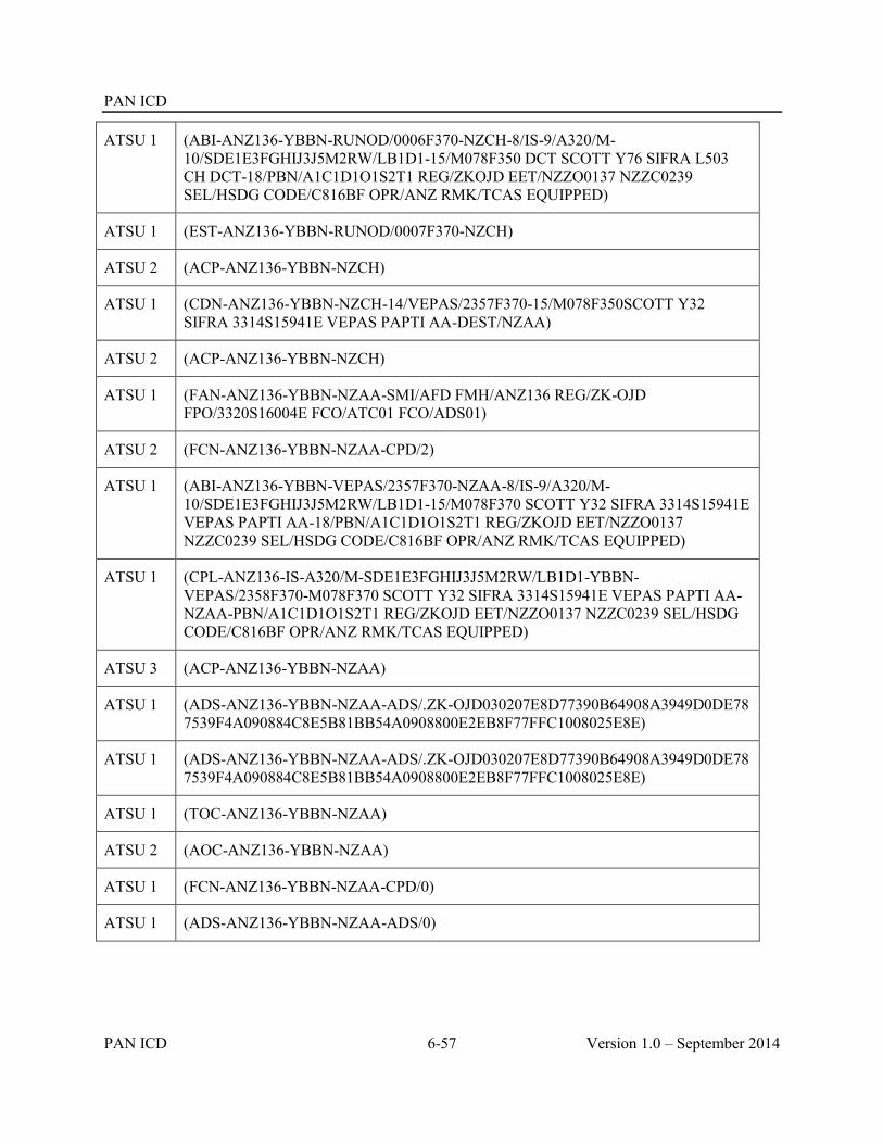
PAN ICD
PAN ICD 6-57 Version 1.0 – September 2014
ATSU 1 (ABI-ANZ136-YBBN-RUNOD/0006F370-NZCH-8/IS-9/A320/M-10/SDE1E3FGHIJ3J5M2RW/LB1D1-15/M078F350 DCT SCOTT Y76 SIFRA L503 CH DCT-18/PBN/A1C1D1O1S2T1 REG/ZKOJD EET/NZZO0137 NZZC0239 SEL/HSDG CODE/C816BF OPR/ANZ RMK/TCAS EQUIPPED)
ATSU 1 (EST-ANZ136-YBBN-RUNOD/0007F370-NZCH)
ATSU 2 (ACP-ANZ136-YBBN-NZCH)
ATSU 1 (CDN-ANZ136-YBBN-NZCH-14/VEPAS/2357F370-15/M078F350SCOTT Y32 SIFRA 3314S15941E VEPAS PAPTI AA-DEST/NZAA)
ATSU 2 (ACP-ANZ136-YBBN-NZCH)
ATSU 1 (FAN-ANZ136-YBBN-NZAA-SMI/AFD FMH/ANZ136 REG/ZK-OJD FPO/3320S16004E FCO/ATC01 FCO/ADS01)
ATSU 2 (FCN-ANZ136-YBBN-NZAA-CPD/2)
ATSU 1 (ABI-ANZ136-YBBN-VEPAS/2357F370-NZAA-8/IS-9/A320/M-10/SDE1E3FGHIJ3J5M2RW/LB1D1-15/M078F370 SCOTT Y32 SIFRA 3314S15941E VEPAS PAPTI AA-18/PBN/A1C1D1O1S2T1 REG/ZKOJD EET/NZZO0137 NZZC0239 SEL/HSDG CODE/C816BF OPR/ANZ RMK/TCAS EQUIPPED)
ATSU 1 (CPL-ANZ136-IS-A320/M-SDE1E3FGHIJ3J5M2RW/LB1D1-YBBN-VEPAS/2358F370-M078F370 SCOTT Y32 SIFRA 3314S15941E VEPAS PAPTI AA-NZAA-PBN/A1C1D1O1S2T1 REG/ZKOJD EET/NZZO0137 NZZC0239 SEL/HSDG CODE/C816BF OPR/ANZ RMK/TCAS EQUIPPED)
ATSU 3 (ACP-ANZ136-YBBN-NZAA)
ATSU 1 (ADS-ANZ136-YBBN-NZAA-ADS/.ZK-OJD030207E8D77390B64908A3949D0DE787539F4A090884C8E5B81BB54A0908800E2EB8F77FFC1008025E8E)
ATSU 1 (ADS-ANZ136-YBBN-NZAA-ADS/.ZK-OJD030207E8D77390B64908A3949D0DE787539F4A090884C8E5B81BB54A0908800E2EB8F77FFC1008025E8E)
ATSU 1 (TOC-ANZ136-YBBN-NZAA)
ATSU 2 (AOC-ANZ136-YBBN-NZAA)
ATSU 1 (FCN-ANZ136-YBBN-NZAA-CPD/0)
ATSU 1 (ADS-ANZ136-YBBN-NZAA-ADS/0)

PAN ICD
Version 1.0 – September 2014 6-58 PAN ICD
6.6.4.11 Example 11 – Abbreviated coordination with TRU update
6.6.4.11.1 ATSU 1 transmits a notification message (ABI) to ATSU 2. The ABI contains Estimate data of EVONN at 0130 at F330.
6.6.4.11.2 ATSU 1 transmits an abbreviated coordination message (EST) to ATSU 2. The proposed coordination contains Estimate data of EVONN at 0130 at FL330. ATSU 2 accepts the proposed coordination conditions by responding with an ACP.
6.6.4.11.3 ATSU 1 transmits a TRU message to ATSU 2, providing a coordination update that the aircraft has been instructed to maintain FL200 and assigned a heading of 100 degrees magnetic.
6.6.4.11.4 ATSU 1 has not received any AIDC or application management messages from ATSU 3 for a system parameter, and so an ASM is transmitted to ATSU 3.
6.6.4.11.5 ATSU 1 proposes a transfer of control responsibility by transmitting a TOC to ATSU 2. ATSU 2 accepts control responsibility by responding with an AOC.
ATSU 1 (ABI-UAE412/A1415-YSSY-EVONN/0130F330-NZAA-8/IS-9/A388/H-10/SADE3GHIJ2J3J4J5M1RWXY/LB2D1-15/N0482F390 3357S15131E EVONN L521 WALTZ/N0482F330 L521 ESKEL/N0482F410 L521 LUNBI AA-18/PBN/A1B1C1D1L1O1S2T2 DOF/140116 REG/A6EEF EET/YBBB0014 NZZO0124 SEL/BPDR CODE/896185 RMK/TCAS ADSB)
ATSU 1 (EST-UAE412/A1415-YSSY-EVONN/0130F330-NZAA)
ATSU 2 (ACP-UAE412/A1415-YSSY-NZAA)
ATSU 1 (TRU-UAE412/A1415-YSSY-NZAA-HDG/100 CFL/F200)
ATSU 1 (ASM)
ATSU 1 (TOC-UAE412/A1415-YSSY-NZAA)
ATSU 2 (AOC-UAE412/A1415-YSSY-NZAA)

PAN ICD
PAN ICD 6-59 Version 1.0 – September 2014
6.6.4.12 Example 12 – ACI coordination and use of ADS message
6.6.4.12.1 The route of the aircraft is such that it will enter the airspace of ATSU 2, as well as the ACI associated with ATSU 3.
6.6.4.12.2 ATSU 1 transmits a notification message (ABI) to ATSU 2. The ABI contains Estimate data of 2925S16300E at 0529 descending from F320 to F300. In addition, the aircraft has been cleared to descend to FL290 after passing 26S170E, and to be maintaining FL290 by NILAX. This level restriction is included in Field 15 of the ABI.
6.6.4.12.3 ATSU 1 also transmits a notification message (ABI) to ATSU 3. The ABI contains Estimate data of 2925S16300E at 0529 descending from F320 to F300. This ABI also contains the level restriction described in the previous paragraph.
6.6.4.12.4 ATSU 1 transmits a coordination message (CPL) to ATSU 2. The proposed coordination contains Estimate data of 2925S16300E at 0529 descending from F320 to F300, as well as the level restriction to descend to FL290. ATSU 2 accepts the proposed coordination without modification by responding with an ACP.
6.6.4.12.5 ATSU 1 transmits a coordination message (CPL) to ATSU 3. The proposed coordination contains Estimate data of 2925S16300E at 0529 descending from F320 to F300, as well as the level restriction to descend to FL290. ATSU 3 accepts the proposed coordination without modification by responding with an ACP.
6.6.4.12.6 ATSU 1 transmits a FAN message to ATSU 2 providing the logon information that ATSU 2 requires to establish a CPDLC connection as well as ADS contracts.
6.6.4.12.7 When an inactive CPDLC connection is established, ATSU 2 transmits a FCN to ATSU 1, including the appropriate HF frequency for the aircraft to monitor.
6.6.4.12.8 ATSU 3 does not support FANS-1/A, but does support the receipt of ADS-C reports via an ADS message. The contents of an ADS-C report received within a system time or position prior to the FIR or ACI boundary are transmitted to ATSU 3 in an ADS message.
6.6.4.12.9 ATSU 1 proposes a transfer of control responsibility by transmitting a TOC to ATSU 2. ATSU 2 accepts control responsibility by responding with an AOC.
6.6.4.12.10Following receipt of another ADS-C report, the contents are transmitted to ATSU 3 in an ADS message.
6.6.4.12.11ATSU 1 terminates the CPDLC connection and transmits an FCN to ATSU 2 notifying them that the CPDLC connection has been terminated.
6.6.4.12.12As the aircraft leaves the ACI associated with ATSU 1, an ADS message is sent to ATSU 3 to notify them that no further ADS messages will be transmitted to them.
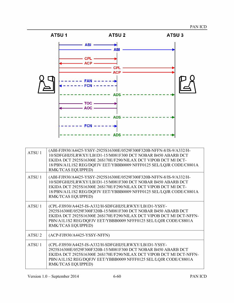
PAN ICD
Version 1.0 – September 2014 6-60 PAN ICD
ATSU 1 (ABI-FJI930/A4425-YSSY-2925S16300E/0529F300F320B-NFFN-8/IS-9/A332/H-10/SDFGHIJ5LRWXY/LB1D1-15/M081F300 DCT NOBAR B450 ABARB DCT EKIDA DCT 2925S16300E 26S170E/F290/NILAX DCT VIPOB DCT MI DCT-18/PBN/A1L1S2 REG/DQFJV EET/YBBB0009 NFFF0125 SEL/LQJR CODE/C8801A RMK/TCAS EQUIPPED)
ATSU 1 (ABI-FJI930/A4425-YSSY-2925S16300E/0529F300F320B-NFFN-8/IS-9/A332/H-10/SDFGHIJ5LRWXY/LB1D1-15/M081F300 DCT NOBAR B450 ABARB DCT EKIDA DCT 2925S16300E 26S170E/F290/NILAX DCT VIPOB DCT MI DCT-18/PBN/A1L1S2 REG/DQFJV EET/YBBB0009 NFFF0125 SEL/LQJR CODE/C8801A RMK/TCAS EQUIPPED)
ATSU 1 (CPL-FJI930/A4425-IS-A332/H-SDFGHIJ5LRWXY/LB1D1-YSSY-2925S16300E/0529F300F320B-15/M081F300 DCT NOBAR B450 ABARB DCT EKIDA DCT 2925S16300E 26S170E/F290/NILAX DCT VIPOB DCT MI DCT-NFFN-PBN/A1L1S2 REG/DQFJV EET/YBBB0009 NFFF0125 SEL/LQJR CODE/C8801A RMK/TCAS EQUIPPED)
ATSU 2 (ACP-FJI930/A4425-YSSY-NFFN)
ATSU 1 (CPL-FJI930/A4425-IS-A332/H-SDFGHIJ5LRWXY/LB1D1-YSSY-2925S16300E/0529F300F320B-15/M081F300 DCT NOBAR B450 ABARB DCT EKIDA DCT 2925S16300E 26S170E/F290/NILAX DCT VIPOB DCT MI DCT-NFFN-PBN/A1L1S2 REG/DQFJV EET/YBBB0009 NFFF0125 SEL/LQJR CODE/C8801A RMK/TCAS EQUIPPED)

PAN ICD
PAN ICD 6-61 Version 1.0 – September 2014
ATSU 3 (ACP-FJI930/A4425-YSSY-NFFN)
ATSU 1 (FAN-FJI930/A4425-YSSY-NFFN-SMI/AFD FMH/FJI930 REG/DQ-FJV FPO/3038S16014E FCO/ATC01 FCO/ADS01)
ATSU 2 (FCN-FJI930/A4425-YSSY-NFFN-CPD/2 FREQ/5565)
ATSU 1 (ADS-FJI930/A4425-YSSY-NFFN-ADS/.DQ-FJV07E9762B84080753363D9D0DEB15CB9F4A0753075BEC6A33BECE4753000E1631100000103EA91E76)
ATSU 1 (TOC-FJI930/A4425-YSSY-NFFN)
ATSU 2 (AOC-FJI930/A4425-YSSY-NFFN)
ATSU 1 (ADS-FJI930/A4425-YSSY-NFFN-ADS/.DQ-FJV07E9762B84080753363D9D0DEB15CB9F4A0753075BEC6A33BECE4753000E1631100000103EA91E76)
ATSU 1 (FCN-FJI930/A4425-YSSY-NFFN-CPD/0)
ATSU 1 (ADS-FJI930/A4425-YSSY-NFFN-ADS/0)
6.6.4.13 Example 13 – Profile confirmation as a safety net
6.6.4.13.1 Due to an error, notification and coordination to ATSU 2 has not occurred, and the controllers in ATSU 1 and ATSU 2 are unaware of this failure.
6.6.4.13.2 ATSU 1 transmits a PCM to ATSU 2 to confirm that the coordination held by ATSU 2 is correct. ATSU 2 updates their flight plan (if one exists, otherwise a flight plan is created from information in the PCM), and confirms that their coordination is up to date by responding with a PCA. Because coordination had not previously been received, the controller in ATSU 2 is alerted, to prompt them to confirm the coordination with ATSU 1 by other means (e.g. voice).
6.6.4.13.3 ATSU 1 proposes a transfer of control responsibility by transmitting a TOC to ATSU 2. ATSU 2 accepts control responsibility by responding with an AOC

PAN ICD
Version 1.0 – September 2014 6-62 PAN ICD
ATSU 1 (PCM-UAE230/A3152-KSEA-7306N07157W/0602F310-OMDB-8/IS-9/B77W/H-10/SWXRGIDE2E3FHJ3J5M1YZ/LB2D1-15/M083F310 7306N07157W 7330N07000W 7500N06000W 7800N04000W 7800N02000W EXITA P190 INSEP P65 VANOS A74 PELOR G476 UREPI B958 BD BD3T FV R11 GUSLI M54 ADILA N82 ADANO N77 MAGRI UR654 SAV UP574 SYZ G666 ORSAR B416 DESDI-18/PBN/A1B1C1D1L1O1S2T1 NAV/RNVD1A1E2 DOF/131125 REG/A6ECH EET/KZSE0010 CZVR0019 CZEG0049 ENOB0618 ENOR0712 ULMM0730 ULLL0754 ULWW0833 UUWV0855 URRV1010 UGGG1103 UDDD1117 OIIX1136 OMAE1324 SEL/GLBJ RALT/CYXE BIKF RMK/ADSB TCAS)
ATSU 2 (PCA-UAE230/A3152-KSEA-OMDB)
ATSU 1 (TOC-UAE230/A3152-KSEA-OMDB)
ATSU 2 (AOC-UAE230/A3152-KSEA-OMDB)
6.6.4.14 Example 14 – Coordination with a restriction in field 15
6.6.4.14.1 ATSU 1 transmits a notification message (ABI) to ATSU 2. The ABI contains Estimate data of 63N030W at 1732 at F340.
6.6.4.14.2 ATSU 1 transmits a coordination message (CPL) to ATSU 2. The proposed coordination contains Estimate data of 63N030W at 1733 at F340
6.6.4.14.3 ATSU 2 responds by transmitting a negotiation message (CDN) to ATSU 1 proposing (or requesting) an amendment to the proposed coordination to F350 with a restriction that the aircraft must cross 62N040W at F350. ATSU 2 accepts the revised coordination by responding with ACP. The restriction is formatted as “F350/62N040W” in Field 15.
6.6.4.14.4 ATSU 1 transmits a FAN message to ATSU 2 providing the logon information that ATSU 2 requires to establish a CPDLC connection as well as ADS contracts.
6.6.4.14.5 When an inactive CPDLC connection is established, ATSU 2 transmits an FCN to ATSU 1, including the appropriate VHF frequency for the aircraft to monitor.
6.6.4.14.6 ATSU 1 proposes a transfer of control responsibility by transmitting a TOC to ATSU 2. ATSU 2 accepts control responsibility by responding with an AOC.
6.6.4.14.7 ATSU 1 terminates the CPDLC connection and transmits an FCN to ATSU 2 notifying them that the CPDLC connection has been terminated.

PAN ICD
PAN ICD 6-63 Version 1.0 – September 2014
ATSU 1 (ABI-ICE631/A3577-BIKF-63N030W/1732F340-KBOS-8/IS-9/B752/M-10/SDFHIRWXYG/LB1-15/M078F340 63N030W 62N040W 60N050W PORGY HO T-18/PBN/A1L1B2B3B4B5D1S1 DOF/131124 REG/TFFIO EET/FLOSI0021 64N030W0032 CZQX0058 62N040W0115 BGGL0117 60N050W0158 CZQX0203 CZQX0242 CZUL0331 CZQM0400 KZBW0414 SEL/EQFL OPR/ICE RALT/BIKF CYYR)
ATSU 1 (CPL-ICE631/A3577-IS-B752/M-SDFHIRWXYG/LB1-BIKF-63N030W/1733F340-M078F340 63N030W 62N040W 60N050W PORGY HO T-KBOS-PBN/A1L1B2B3B4B5D1S1 DOF/131124 REG/TFFIO EET/FLOSI0021 64N030W0032 CZQX0058 62N040W0115 BGGL0117 60N050W0158 CZQX0203 CZQX0242 CZUL0331 CZQM0400 KZBW0414 SEL/EQFL OPR/ICE RALT/BIKF CYYR)
ATSU 2 (CDN-ICE631/A3577-BIKF-KBOS-15/M078F340 63N030W F350/62N040W 60N050W PORGY HO T)
ATSU 1 (ACP-ICE631/A3577-BIKF-KBOS)
ATSU 1 (FAN-ICE631/A3577-BIKF-KBOS-SMI/AFD FMH/ICE631 REG/TF-FIO FPO/6331N02537W FCO/ATC01 FCO/ADS01)
ATSU 2 (FCN-ICE631/A3577-BIKF-KBOS-CPD/2 FREQ/127.900)
ATSU 1 (TOC-ICE631/A3577-BIKF-KBOS)
ATSU 2 (AOC-ICE631/A3577-BIKF-KBOS)
ATSU 1 (FCN-ICE631/A3577-BIKF-KBOS-CPD/0)


PAN ICD
PAN ICD A-1 Version 1.0 – September 2014
Appendix A Templates for Bilateral Letter of Agreement on AIDC
At an organizational level, the implementation of AIDC to enable data transfers between automated ATS systems is accomplished under the authority and strict operational terms of a bilateral letter of agreement or memorandum of understanding on AIDC arrangements that must be established between the two ATSUs involved. Depending on the particular circumstances, the legally less sophisticated Memorandum of Understanding (MOU) format could be used for the initial implementation of AIDC until the more formalized Letter of Agreement (LOA) is put in place. The choice of legal instrument will be a decision made by the two ATSUs as they prepare the formal agreement to enable AIDC data transfer between States.
In order to provide guidance in the structure and content of bilateral arrangements, templates have been included in this appendix to assist States in preparing suitable memorandums of understandings/letters of agreement on AIDC arrangements. The templates are based upon documentation developed by Airways New Zealand in implementation evolving AIDC arrangements between Auckland Oceanic and all neighboring States over a period of approximately 10 years commencing from the mid 1990’s. Three templates are included:
Template 1 provides a generic example of a basic Letter of Agreement
Template 2 is an example of an actual Letter of Agreement between Auckland Oceanic (New Zealand) and Brisbane ATS Centre (Australia); and
Template 3 is an example of an actual Memorandum of Understanding between Auckland Oceanic (New Zealand) and Nadi ATM Operations Centre (Fiji).
The templates are intended as guidance material only. It is important to note that although changes in the AIDC arrangements applicable to Auckland Oceanic will occur over time, Templates 2 and 3 will NOT be routinely updated. Accordingly, as the circumstances for each bilateral implementation will differ, appropriate adjustments should be made to the content of the templates to ensure that the resulting MOU or LOA is fit for the purpose intended.

PAN ICD
Version 1.0 – September 2014 A-2 PAN ICD
Template 1
Generic Letter of Agreement
AIDC Procedures
1. The format of AIDC messages (List messages used e.g. ABI, PAC, CDN, CPL, ACP, REJ, MAC, LAM and LRM) are as defined by the Pan Regional (NAT and APAC) AIDC Interface Control Document (ICD) as amended from time to time, unless described otherwise in this LOA.
2. List messages not supported (e.g. “EST, TOC, AOC messages are not supported”).
3. Acceptance of CPL or CDN message is approval of the flight’s profile and requires no further voice communication (i.e. Non-Standard Altitudes, Block Altitudes, and Deviations).
4. (Describe other procedures applicable to the use of AIDC for this LOA. Some examples are listed below)
a. Example only. If there is any doubt with regard to the final coordination data, voice coordination should be used for confirmation.
b. Example only. Receipt of a MAC message must not be interpreted as meaning that the flight plan has been cancelled. Voice coordination must be conducted by the transferring controller to confirm the status of the flight.
c. Example only. Each facility should advise the other facility of any known equipment outage that affects AIDC. In the event of AIDC outage, voice communication procedures will apply.
d. Example only. Truncation. Where route amendment outside the FIR is unavoidable.
i. Terminate the route details at the farthest possible flight plan significant point of the flight and enter “T” immediately following this.
ii. Without amending the originally received details, every effort is to be made to truncate the route at a minimum of one significant point beyond the adjacent FIR to provide an entry track in that FIR.
AIDC Messages
(For each message used describe when it will be sent by each ATSU under the parameter column and use the Notes column to describe other applicable information for the message use by each ATSU. The data below provides an example of the type of information that could be incorporated.)
Messages Parameter Notes ABI ATSU1: Sends ABI approx. 80 minutes
prior to boundary (73 minutes prior to the 50 nm expanded sector boundary). ATSU2: Sends ABI approx. 87 minutes prior to boundary (80 minutes prior to the 50 nm expanded sector boundary). (Note: An updated ABI will not be sent once a CPL has been sent.)
ATSU1 : ATSU2
Updated ABI’s will be sent automatically if there is any change to profile. ABI is sent automatically and is transparent to the controller. ABI automatically updates the receiving unit’s flight data record.

PAN ICD
PAN ICD A-3 Version 1.0 – September 2014
CPL ATSU1 : ATSU2
Send CPL messages approx. 37 minutes prior to the boundary (30 minutes prior to the 50 nm expanded sector boundary).
ATSU1 : ATSU2
CPL messages should be sent by the transferring controller in sufficient time to allow the completion of coordination at least 30 minutes prior to the boundary or 30 minutes prior to the aircraft passing within 50nmof the FIR boundary for information transfers.
CDN ATSU1 : ATSU2
CDN messages are sent by either the transferring or receiving facility to propose a change once the coordination process has been completed, i.e., CPL sent and ACP received. CDN’s must contain all applicable profile restrictions (e.g. weather deviations, speed assignment, block altitude). If the use of a CDN does not support this requirement, then verbal coordination is required.
ATSU1 : ATSU2
The APS will display a flashing “DIA” until receipt of ACP. If ACPJ not received within ten (10) minutes, controller is alerted with a message to the queue. CDN messages are not normally used for coordination of reroutes; however, with the receiving facilities approval a CDN may be used to coordinate a reroute on a critical status aircraft such as in an emergency.
PAC ATSU1 : ATSU2
PAC messages will normally be sent when the time criteria from the departure point to the boundary is less than that stipulated in the CPL.
ATSU1 : ATSU2
Will respond to a PAC message with an ACP. PAC messages should be verbally verified with receiving facility.
ACP ATSU1 : ATSU2
ATSU1 : ATSU2
The APS will display a flashing “DIA” until receipt of ACP. If ACP not received within ten (10) minutes, controller is alerted with a message to the queue.
TOC ATSU1 : ATSU2
Not supported. Implicit hand in/off.
AOC ATSU1 : ATSU2
Not supported. Implicit hand in/off.
MAC ATSU1 : ATSU2
MAC messages are sent when a change to the route makes the other facility no longer the “next” responsible unit.
ATSU1 : ATSU2
Receipt of a MAC message must not be interpreted as meaning that the flight plan has been cancelled. Voice coordination must be conducted by the transferring controller to confirm the status of the flight.
REJ ATSU1 : ATSU2
REJ messages are sent in reply to a CDN message when the request change is unacceptable
ATSU1 : ATSU2
REJ messages are sent only as a response to a CDN message.

PAN ICD
Version 1.0 – September 2014 A-4 PAN ICD
Template 2
Example: Auckland Oceanic – Brisbane ATS Centre
Letter of Agreement
Coordination – General
Transfer of Control Point
The Transfer of Control Point (TCP) should be either on receipt of an Acceptance of Control (AOC) to a Transfer of Control (TOC) or the common FIR boundary, whichever occurs first. The TCP should also be the point of acceptance of primary guard.
All ATS units should coordinate an estimate for the FIR boundary at least thirty (30) minutes prior to the boundary. Such coordination constitutes an offer of transfer of responsibility.
After the estimate for the FIR boundary has been sent, units should coordinate any revised estimate that varies by 3 minutes or more.
Communication Systems
Use of communications systems coordination between adjacent units should be in the following order of priority:
a. ATS Interfacility Data Communication (AIDC)
b. AIDC messages and procedures are specified in the following sections;
c. ATS direct speech circuits;
d. International telephone system;
e. Any other means of communication available.
AIDC Messages AIDC message format will be in accordance with the Pan Regional Interface Control Document (PAN ICD) for AIDC, as amended from time to time, unless described otherwise in the LOA.
Successful coordination via AIDC occurs on receipt of an ACP message in response to an EST message.
Each centre should advise the other of any known equipment outage that affects AIDC.
Continued to next page

PAN ICD
PAN ICD A-5 Version 1.0 – September 2014
Coordination – General, Continued
AIDC Message Parameters
The following table details the AIDC parameters and message to be used.
Message Parameter Notes
ABI EUROCAT: 5-60 minutes prior to COP (Note: An updated ABI will not be sent once an EST has been sent)
OCS: 40 minutes prior 50nm expanded boundary
ABI is sent automatically and is transparent to controller. ABI automatically updates flight plan.
EST EUROCAT: 40 minutes prior to COP
OCS: 40 minutes prior 50mn expanded boundary
Any changes to EST level or estimate conditions as detailed in LOA to be notified by voice after initial coordination completed. See notes below on voice procedures. EST is required to track generation in EUROCAT.
ACP EUROCAT: Sends automatic ACP on receipt of EST
OCS: Sends automatic ACP on receipt of EST
EUROCAT: If ACP not received within 4 minutes the sending controller is alerted. Sending controller will initiate voice coordination if ACP is not received within 4 minutes of sending EST.
Receiving controller will initiate voice coordination if proposed EST conditions are not acceptable.
OCS: If ACP is not received within 5 minutes the sending controller is alerted. Sending controller will not initiate voice coordination if ACP is not received within 5 minutes of sending EST. Receiving controller will initiate voice coordination if proposed EST conditions are not acceptable.
TOC EUROCAT: Sent automatically 5 minutes prior to boundary
OCS: Sent automatically 2 minutes prior to boundary
AOC EUROCAT: Sent automatically on controller acceptance of a TOC
OCS: Sent automatically on receipt of a TOC
Continued to next page

PAN ICD
Version 1.0 – September 2014 A-6 PAN ICD
Coordination – General, Continued
AIDC Message (continued)
Message Parameter Notes
CDN EUROCAT: Manually by the controller when required
Responses to the CDN should be ACP or REJ only – there will be no CDN negotiations.
CDN messages will be sent by Brisbane only to revise coordination on eastbound flights.
CDN messages may be used to coordinate changes to estimate or assigned altitude only.
Only on CDN dialogue may be open per aircraft at any time.
Not to be used if the aircraft will not be maintaining the assigned altitude 10 minutes prior to the TCP.
MAC As per ICD
LRM As per ICD. Controller alerted on receipt
LAM As per ICD. Controller alerted on non-receipt
Amendment to Flight Data Record
Route amendment – routes/waypoints may be added/deleted as long as they do not change the original intent or integrity of the flight plan information.
Truncation – where route amendment outside the FIR unavoidable:
a. Terminate the route details at the farthest possible ‘flight planned’ point of the flight outside the FIR and enter “T” immediately following this.
b. If insufficient ‘flight planned’ point exist outside the FIR for truncation, insert the first ‘defined’ point in the adjoining FIR and enter “T” immediately following this.
c. The minimum acceptable truncation point must be at least the first point in the adjoining FIR.
d. Every effort is to be made to truncate the route at a minimum of one point beyond the adjacent international FIR to provide an entry track in to that FIR.
Continued on next page

PAN ICD
PAN ICD A-7 Version 1.0 – September 2014
Coordination – General, Continued
Address Forwarding and Next Data Authority
Brisbane ATSC and Auckland OAC should send automatic Next Data Authority (NDA) and Address Forwarding (CAD) for data link aircraft as per the following table:
Brisbane ATSC Auto NDA sent 22 minutes prior to the FIR boundary Auto CAD sent 20 minutes prior to the FIR boundary
Auckland OAC Auto NDA sent 40 minutes prior to the FIR boundary Auto CAD sent 35 minutes prior to the FIR boundary
Voice Coordination
Voice coordination is not required when AIDC messaging has been successful to offer and accepts transfer of control.
However, the receiving controller will initiate voice coordination if the proposed AIDC EST conditions are not acceptable.
If AIDC messaging is not to be sent following voice coordination, it should be stated as part of the voice coordination by use of the phrase “AIDC messaging will not be sent”. A read back is required.
Voice Coordination is required for aircraft operating under any of the following conditions:
block level clearance;
weather deviations;
offset track; or
Mach Number technique.
Read backs should comprise all elements of the voice coordination passed by the transferring controller. Read back by the receiving unit confirms acceptance of the offer of transfer of control subject to any other conditions negotiated.
Hemstitch Flights
A hemstitch flight is any flight that will remain within the New Zealand FIR for less time than the NDA VSP (40 minutes) prior to the flight entering the Brisbane FIR.
Auckland AOC should voice coordinate any hemstitch flight.
Continued on next page
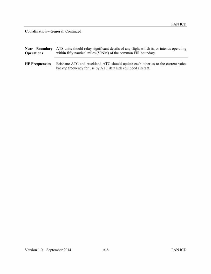
PAN ICD
Version 1.0 – September 2014 A-8 PAN ICD
Coordination – General, Continued
Near Boundary Operations
ATS units should relay significant details of any flight which is, or intends operating within fifty nautical miles (50NM) of the common FIR boundary.
HF Frequencies Brisbane ATC and Auckland ATC should update each other as to the current voice backup frequency for use by ATC data link equipped aircraft.

PAN ICD
PAN ICD A-9 Version 1.0 – September 2014
Template 3
Example: Auckland Oceanic – Nadi ATM Operations Centre
Memorandum of Understanding Between
Airways New Zealand Limited And
Nadi ATM Operations Centre
Subject Air Traffic Services Inter-facility Data Communications (AIDC) Coordination Procedures
Validity Period This Memorandum of Understanding should be effective from 0506300300 UTC and may be cancelled by either party with written notice.
Signatories The following signatories have ratified this Agreement:
Authority Signature Date
(Name of Officer) Oceanic Business Unit Manager Airways New Zealand
(Name of Officer) Manager, Operations Strategic Air Services Limited Fiji
(Name of Officer) Chairman, ATM Projects Committee, Airports Fiji Limited Fiji
Continued on next page

PAN ICD
Version 1.0 – September 2014 A-10 PAN ICD
Memorandum of Understanding, Continued
Purpose To establish procedures to permit AIDC messages for coordination purposes to be transmitted by Auckland Oceanic and received by Nadi Air Traffic Management Operations Centre (ATMOC).
Scope This MOU between Auckland and Nadi is supplementary to the procedures contained in the Airways Corporation of New Zealand Limited and Airport Fiji Limited LOA, dated 25 November 2004. Revision to this MOU should be made only with the concurrence of all parties.
Procedures 1. The format of AIDC messages (ABI, EST, PAC, CDN, CPL, ACP, REJ, TOC, AOC, MAC, LAM and LRM) is defined by the Asia/Pacific/North Atlantic Regional AIDC Interface Control Document (ICD) version 2.0. The optional formats for the coordination of block levels, weather deviations and Mach Number Technique have not been implemented.
2. Each facility should advise the other facility of any known equipment outage that will affect AIDC. In the event of AIDC outage, voice coordination procedures will apply.
3. The following table details the messaging parameters and additional information for each message.
Message Parameter Notes ABI Non Hem-stitching flights
Auckland: Sends ABI 48 minutes prior to boundary (Note: An updated ABI will not be sent once an EST has been sent)
Updated ABIs will be sent automatically if there is any change to profile. ABI is sent automatically and is transparent to the controller. ABI automatically updates the receiving units flight data record
EST (general) Non Hem-stitching flights
Auckland: Sends EST 38 minutes prior to boundary
EST is sent automatically and automatically coordinates the receiving unit’s flight data record. Any change to the EST (level or estimate) conditions as detailed in LOA are to be notified by voice after the initial coordination completed. See section below on voice procedures
Continued on next page

PAN ICD
PAN ICD A-11 Version 1.0 – September 2014
Memorandum of Understanding, Continued
Message Parameter Notes ABI & EST Hem-stitch flights
Auckland: Sends ABI & EST messages for flights that re-enter the Nadi FIR as soon as the aircraft enters NZZO FIR
In these cases the ABI and EST are sent automatically
PAC Auckland: Voice coordination will take place in those situations when a PAC is sent
ACP Auckland: Sent automatically on receipt of EST Nadi: Sent automatically on receipt of EST or PAC
Auckland: The APS will display a flashing “DIA” until receipt of ACP. If ACP not received within ten (10) minutes, controller is alerted with a message to the queue
TOC Auckland: Sent automatically 2 minutes prior to boundary
This proposes a hand-off to the receiving unit
AOC Auckland: Sent automatically on receipt of TOC Nadi: Sent by the controller on acceptance of TOC
This completes the hand-off proposal
MAC Auckland: Sent manually when a change to the route makes Nadi no longer the “next” responsible unit
Receipt of a MAC message should not be interpreted as meaning that the flight plan has been cancelled. Voice coordination should be conducted by the receiving controller to confirm the status of the flight
Continued on next page

PAN ICD
Version 1.0 – September 2014 A-12 PAN ICD
Memorandum of Understanding, Continued
Procedures, Continued
4. Block levels, offsets, and weather deviations, or Mach Number Techniques are not included in the current version of AIDC messaging. Voice coordination should be conducted for aircraft operating under these circumstances.
5. If there is any doubt with regard to the final coordination conditions, voice coordination should be used for confirmation.
6. Truncation – Where route amendment outside the FIR is unavoidable:
Terminate the route details at the farthest possible ‘flight planned’ point of the flight and enter “T” immediately following this.
Without amending the originally received details, every effort is to be made to truncate the route a minimum of one point beyond the adjacent FIR to provide an entry track in to that FIR
7. For any reason where changes to this MOU are advisable the requesting unit should propose the pertinent revision. The revision should be emailed of faxed to the appropriate Manager for action. The Manager or the designated deputies should agree by email or telephone, followed by a confirming fax message signed by all parties. Formal exchange of signed copies of the amended MOW should take place as soon as practicable thereafter.
Hemstitch Flights
A Hemstitch flight is any flight that vacates FIR 1 and transits FIR 2 before re-entering FIR 1.
When a hemstitching flight vacates FIR 1 and then re-enter FIR 2 30 minutes or less later, the re-entry coordination is considered to have been completed when coordination for the initial entry is completed and further coordination is only required if the aircraft requests:
A weather deviation, or A level change, or Any change to the EST time is received, or If there is any doubt that the receiving FIR has the correct boundary
information AIDC messages (ABI and EST) will still be sent by Auckland, but only when the aircraft flight state becomes active control. For hem stitching flights this will usually be when the aircraft enters the NZZO FIR, therefore these messages will normally be sent at less than 30 minutes prior to the TCP.
Continued on next page
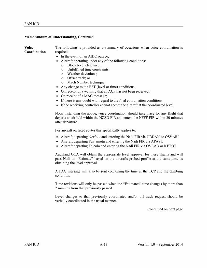
PAN ICD
PAN ICD A-13 Version 1.0 – September 2014
Memorandum of Understanding, Continued
Voice Coordination
The following is provided as a summary of occasions when voice coordination is required: In the event of an AIDC outage; Aircraft operating under any of the following conditions:
o Block level clearance; o Unfulfilled time constraints; o Weather deviations; o Offset track; or o Mach Number technique
Any change to the EST (level or time) conditions; On receipt of a warning that an ACP has not been received; On receipt of a MAC message; If there is any doubt with regard to the final coordination conditions If the receiving controller cannot accept the aircraft at the coordinated level;
Notwithstanding the above, voice coordination should take place for any flight that departs an airfield within the NZZO FIR and enters the NFFF FIR within 30 minutes after departure.
For aircraft on fixed routes this specifically applies to:
Aircraft departing Norfolk and entering the Nadi FIR via UBDAK or OSVAR/ Aircraft departing Fua’amotu and entering the Nadi FIR via APASI; Aircraft departing Faleolo and entering the Nadi FIR via OVLAD or KETOT
Auckland OCA will obtain the appropriate level approval for these flights and will pass Nadi an “Estimate” based on the aircrafts probed profile at the same time as obtaining the level approval.
A PAC message will also be sent containing the time at the TCP and the climbing condition.
Time revisions will only be passed when the “Estimated” time changes by more than 2 minutes from that previously passed.
Level changes to that previously coordinated and/or off track request should be verbally coordinated in the usual manner.
Continued on next page

PAN ICD
Version 1.0 – September 2014 A-14 PAN ICD
Memorandum of Understanding, Continued
Notification of Descent Restrictions by Nadi
Auckland OCS controllers may issue descent to aircraft entering the NZZO FIR from the NFFF FIR and landing at Norfolk, Tonga or Samoa without requesting descent restrictions from Nadi provided descent is commenced after the aircraft has passed the following positions. Should Nadi have any restrictions for descent, they will advise Auckland at least 10 minutes prior to these positions:
For aircraft entering NZZO FIR via:
UPDAK descent to commence after NOGOL
OSVAR descent to commence after OSVAR minus 10 minutes
APASI descent to commence after ASAPI
All other occasions, descent to commence after the aircraft has crossed the FIR boundary.

PAN ICD
PAN ICD B-1 Version 1.0 – September 2014
Appendix B Regionally Specific Messages
B.1 TDM (TRACK DEFINITION MESSAGE)
B.1.1 Purpose.
B.1.1.1 Used to distribute Pacific track information to affected ATSUs and Aeronautical Operational Control (AOCs) for flight planning. The message contains track definition and activity time periods.
B.1.2 Message Format.
B.1.2.1 Track Name. The track name consists of two fields. The first field is always ‘TRK’. The second field is the track identifier. The track identifier consists of 1 to 4 alphanumeric characters.
B.1.2.2 General Information. General information contains:
a. Date and time the track was generated and message number tor that particular track in YYMMDDHHMMNN format where NN represents the message number. The initial TDM date/time message number group will look like: 941006134501. Message numbers 02 to 99 indicate TDM amendments or revisions. Note that an additional preceding zero may be required to provide the correct number of digits. b. Track status. Blank field for initial message or “AMDT” for amendment.
B.1.2.3 Activity Time Interval. This field consists of two date/time pairs, separated by a blank character, in the following format: YYMMDDHHMM YYMMDDHHMM.
The first date/time pair represents the track activation, while the second is the track termination date/time.
Example: 9410070300 9410071500.
This example represents an activation date/time of October 7, 1994, at 0300 UTC and a termination date/time of October 7, 1994 at 1500 UTC.
B.1.2.4 Track Waypoint. This field contains the set of waypoints defining the track from the ingress fix to the egress fix. Waypoints are represented as latitude/longitude or named en route points. Waypoints are separated from each other by a blank space. Note that an additional preceding zero may be required to provide the correct number of digits For example:
60N150W 60N160W, or NORMU NUMMI, or FINGS 5405N13430W, etc.
B.1.2.5 Optional Fields
a. Level: This optional field will not be used in the Pacific operations since levels are published in separate documents, e.g. Pacific SUPPS (Doc 7030). A rack level list may be specified for the east and westbound directions of flight and a track level list would contain the complete list of levels available on the track for the specified direction of flight. The levels would apply to all waypoints in the track waypoint list. b. Connecting routes (RTS): The RTS field is an optional field not normally used by automated ATS systems. When used, it is located after the waypoint list (before the remarks

PAN ICD
Version 1.0 – September 2014 B-2 PAN ICD
field) and begins with the keyword ’RTS/’ at the beginning of a line. Each line of the RTS field contains a single connecting route (to the ingress fix or from the egress fix).
B.1.2.6 Remarks: The Remarks subfield is a free text field that can contain additional comments. If there are no remarks a zero (0) is inserted as the only text. The remarks subfield begins with ’RMK/’.
Examples
The following TDM describes a route connecting Honolulu and Japan:
(TDM TRK A 940413124001
9404131900 9404140800
LILIA 27N170W 29N180E 31N170E 32N160E MASON
RTS/PHNL KEOLA2 LILIA
MASON OTR 15 MOLT OTR 16 SUNNS OTR20 LIBRA RJAA RMK/0)
The following TDM Revision describes a revision to the TDM shown above.
(TDM TRK A 940413131502 AMDT 9404131900 9404140800 LILIA 27N170W 29N180E 30N170E 32N160E MASON RTS/PHNL KEOLA2 LILIA MASON OTR15 SMOLT OTR16 SUNNS OTR20 LIBRA RJAA RMK/0)
In the example given above, the message number (as delineated by the last two digits of the message generation date/time group) indicates it as the second (“2”) message for the track. This is followed by ‘AMDT’ to signify the previous message has been amended.
B.2 NAT (ORGANIZED TRACK STRUCTURE)
B.2.1 Purpose.
B.2.1.1 Used to publish the NAT organized track structure and the levels available. The message may be divided into several parts to enable it to be transmitted.
B.2.2 Message Format.
ATS Field Description
3 Message type
Text Structured text

PAN ICD
PAN ICD B-3 Version 1.0 – September 2014
B.2.3 Structured Text Format.
B.2.3.1 It is required to adhere strictly to the syntax described hereafter in order to facilitate automated processing of NAT messages.
B.2.3.2 In the examples below, text between angle brackets should be understood to represent characters by their ASCII name. E.g. <sp> stands for ‘space character’, <cr> for ‘carriage return>, <lf> for ‘line feed’, and any combination <crlf> is the same as <cr><lf>. No control character should be inserted in the message text unless specified as in the examples below. This restriction of course applies to <cr> and <lf> as well as any other control character.
B.2.3.3 It should be noted that NAT Track messages should otherwise follow current AFTN syntax requirements as expressed in ICAO Annex 10, e.g. that the alignment function with the message text, header and trailer is composed of a single <cr> followed by a single <lf>. However modern systems should also be able to process the older alignment function composed of a double <cr> followed by a single <lf> as if it were a single <cr> followed by a single <lf> for backward compatibility reasons and to facilitate transition.
B.2.3.4 Characters in bold underlined in Message Text (syntax) column are to be replaced or dealt with as explained in the Description column.
B.2.3.5 The structured text is first composed of a NAT message header, as follows:
Id Message Text (syntax) Description (semantics)
1 (NAT-a/b<sp>
TRACKS<sp>
a designates the part number in the b parts of the NAT message (a and b are one decimal digit)
2 FLS<sp>nnn/mmm
<sp>INCLUSIVE
nnn and mmm designating the minimum and maximum concerned flight levels in hundreds of feet (three decimal digits)
3 <crlf>
4 month<sp>d1/h1m1Z
<sp>TO<sp> month<sp>d2/h2m2Z
Validity time with:
month: for the month of validity full month name in letters
d1/h1m1: beginning time of validity
d2/h2m2: ending time of validity(day/hour minute, 2 digits each, no space, leading zero required if number is less than 10)
5 <crlf>
6 PART<sp>a
<sp>OF<SP>
b<sp> PARTS-
a and b textual numbers (ONE, TWO, THREE, FOUR) or one decimal digit. Both numbers should represent the same digits as referred to in item Id 1 above.

PAN ICD
Version 1.0 – September 2014 B-4 PAN ICD
Id Message Text (syntax) Description (semantics)
Terminal character S may be omitted if b is ONE.
7 <crlf><crlf>
B.2.3.6 Following the NAT message header is a repeat of the following structure for each North Atlantic Track part of the message. If the resulting NAT message text is longer than 1800 characters, it must be separated into as many parts as necessary. Separation must happen between individual North Atlantic Track descriptions, not within an individual description.
Id Message Text (syntax) Description (semantics)
8 L letter designating the name of the NAT track.
One of:
ABCDEFGHIJKLM for Westbound tracks. The most northerly Track of the day is designated as NAT Track Alpha, the adjacent Track to the south as NAT Track Bravo, etc.
NPQRSTUVWXYZ for Eastbound tracks The most southerly Track of the day is designated as NAT Track Zulu, the adjacent Track to the north as NAT Track Yankee, etc.
Tracks must be defined in sequence starting at any letter in the appropriate set, each following track using the immediately following letter in that set, e.g. UVWXYZ or ABCDE etc.
The first track in the message should be the most northerly one and each subsequent track should be the next one towards the south.
9 <sp>
10 list of points Each point, separated by a space, is either significant points (named points from the published ICAO list of fixes) or a LAT/LONG given in degrees or degrees and minutes. At present only whole degrees are used. Acceptable LAT/LONG syntaxes are:
xx/yy
xxmm/yy
xx/yymm
xxmm/yymm

PAN ICD
PAN ICD B-5 Version 1.0 – September 2014
Id Message Text (syntax) Description (semantics)
Where xx is the north latitude, yy the west longitude, and mm the minutes part of the latitude or longitude.
11 <crlf>
12 EAST LVLS<sp>List of allowed levels
list the allowed flight levels for eastbound flights. This list can contain NIL if there is no allowed level or a list of numbers (3 decimal digits) for each allowed level separated by a space.
13 <crlf>
14 WEST LVLS<sp>List of allowed levels
list the allowed flight levels for westbound flight. This list can contain NIL if there is no allowed level or a list of numbers (3 decimal digits) for each allowed level separated by a space.
15 <crlf>
16 EUR<sp>RTS<sp> WEST<sp>XXX<sp> VIA<sp>RP
Or
EUR<sp>RTS<sp> WEST<sp> NIL
(optional field)
Note that the indentation does not indicate the presence of space characters, it is a presentation mechanism to highlight two variant syntaxes for this field.
Description of European links to the tracks, this description will be given separately for Eastbound and/or Westbound flights.
XXX designating the Irish/UK route structure linked to the NAT track.
RP designating the point recommended to be over flown by westbound flights for joining the NAT track.
The text “VIA<sp>RP” is optional.
Or
There is no European link.
17 <crlf>
18 NAR<sp>list
Or
NAR<sp>NIL
(optional)
Description of North American links to the tracks list:
list of North American airways recommended to be overflown by flights for joining or leaving the NAT

PAN ICD
Version 1.0 – September 2014 B-6 PAN ICD
Id Message Text (syntax) Description (semantics)
track
Or
There are no recommended North American airways
19 -
20 <crlf><crlf>
B.2.3.7 And to terminate the NAT message is composed of a trailer
Id Message Text (syntax) Description (semantics)
21 <crlf>
22 REMARKS<crlf>text
<crlf>
This field is optional and can only be present in the last part of a multipart NAT message, or in the unique part in case of a mono-part NAT message.
The remark text must contain the Track Message Identifier (TMI).
It is recommended to consistently place the TMI in the first remark.
The syntax for the TMI is as follows:
Any text may precede the keywords that identify the TMI.
The TMI is recognized as the first occurrence of the string (without the quotes) “TMI<sp>IS<sp>xxx” is the TMI and “a” the optional track message revision letter.
To facilitate automated processing, this string should be followed by a space character before any subsequent remark text is inserted in the track message.
The TMI should be the Julian calendar day in the year – i.e. starting at one (001) on the first of January or each year, 002 for second of January etc.
23 END<sp>OF<sp>PART<sp>a<sp>OF<sp>b
a and b textual numbers (ONE, TWO, THREE, FOUR) or one decimal digit.

PAN ICD
PAN ICD B-7 Version 1.0 – September 2014
Id Message Text (syntax) Description (semantics)
<sp>PARTS) Both numbers must be the same as in field 6 above.
Terminal character S may be omitted if b is ONE.
B.2.3.8 Example of westbound message set.
(NAT-1/3 TRACKS FLS 310/390 INCLUSIVE JULY 01/1130Z TO JULY 01/1800Z PART ON OF THREE PARTS- A 57/10 59/20 61/30 62/40 62/50 61/60 RODBO EAST LVLS NIL WEST LVLS 320 340 360 380 EUR RTS WEST NIL NAR N498C N4996C N484C- B 56/10 58/20 60/30 61/40 60/50 59/60 LAKES EAST LVLS NIL WEST LVLS 310 330 350 370 390 EUR RTS WEST 2 NAR N434C N428C N424E N416C C 55/10 57/20 59/30 60/40 59/50 PRAWN YDP EAST LVLS NIL WEST LVLS 310 32 330 340 350 360 370 380 390 EUR RTS WEST NIL NAR N322B N326B N328C N336H N346A N348C N352C N356C N362B- D MASIT 56/20 58/30 59/40 58/50 PORGY HO EAST LVL NIL WEST LVLS 310 320 330 340 350 360 370 380 390 EUR RTS WEST DEVOL NAR N284B N292C N294C N298H N302C N304E N306C N308E N312A- E 54/15 55/20 57/30 57/40 56/50 SCROD VALIE EAST LVLS NIL WEST LVLS 310 320 330 340 350 360 370 380 390 EUR RTS WEST BURAK NAR N240C N248C N250E N252E N254A N256A N258A N260A- END OF PART ONE OF THREE PARTS (NAT-2/3 TRACKS FLS 310.390 INCLUSIVE JULY 01/1130Z TO JULY 01/1800Z PART TWO OF THREE PARTS F 53/15 54/20 56/30 56/40 55/50 OYSTR STEAM EAST LVLS NIL

PAN ICD
Version 1.0 – September 2014 B-8 PAN ICD
WEST LVLS 310 320 330 340 350 360 370 380 390 EUR RTS WEST GUNSO NAR NIL- END OF PART TWO OF THREE PARTS) (NAT-3/3 TRACKS FLS 310/390 INCLUSIVE JULY 01/1130Z TO JULY 01/1800Z PART THREE OF THREE PARTS- H BANAL 43/20 44/30 44/40 43/50 JEBBY CARAC EAST LVLS NIL WEST LVLS 310 350 370 EUR RTS WEST DIRMA NAR N36E N44B-
REMARKS:
1. TMI IS 182 AND OPERATORS ARE REMINDED TO INCLUDE THE TMI NUMBER AS PART OF THE OCEANIC CLEARANCE READ BACK.
2. OPERATORS ATTENTION IS DRAWN TO CZUL NOTAM A2152/01
3. OPERATORS ATTENTION IS DRAWN TO UK NOTAMS A1098/01 AND G0120/01
4. MNPS AIRSPACE EXTENDS FROM FL285 TO FL420. OPERATORS ARE REMINDED THAT SPECIFIC MNPS APPROVAL IS REQUIRED TO FLY IN THIS AIRSPACE. IN ADDITION, RVSM APPROVAL IS REQUIRED TO FLY BETWEEN FL310 AND FL390 INCLUSIVE.
5. EIGHTY PERCENT OR GROSS NAVIGATION ERRORS RESULT FROM POOR COCKPIT PROCEDURES. ALWAYS CARRY OUT PROPER WAY POINT CHECKS.-
END OF PART THREE OR THREE PARTS)
B.2.3.9 Example of eastbound message set.
(NAT-1/1 TRACKS FLS 310/390 INCLUSIVE JULY 01/0100Z TO JULY 01/0800Z PART ONE OF ONE PART- V YAY 53/50 54/40 55/30 56/20 56/10 MAC EAST LVLS 310 320 330 340 350 360 370 380 390 WEST LVLS NIL NAR N125A N129B- W DOTTY 52/50 53/40 54/30 55/20 55/10 TADEX
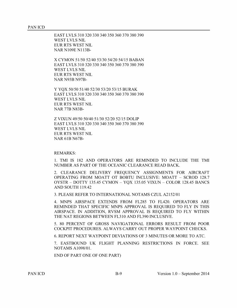
PAN ICD
PAN ICD B-9 Version 1.0 – September 2014
EAST LVLS 310 320 330 340 350 360 370 380 390 WEST LVLS NIL EUR RTS WEST NIL NAR N109E N113B- X CYMON 51/50 52/40 53/30 54/20 54/15 BABAN EAST LVLS 310 320 330 340 350 360 370 380 390 WEST LVLS NIL EUR RTS WEST NIL NAR N93B N97B- Y YQX 50/50 51/40 52/30 53/20 53/15 BURAK EAST LVLS 310 320 330 340 350 360 370 380 390 WEST LVLS NIL EUR RTS WEST NIL NAR 77B N83B- Z VIXUN 49/50 50/40 51/30 52/20 52/15 DOLIP EAST LVLS 310 320 330 340 350 360 370 380 390 WEST LVLS NIL EUR RTS WEST NIL NAR 61B N67B-
REMARKS:
1. TMI IS 182 AND OPERATORS ARE REMINDED TO INCLUDE THE TMI NUMBER AS PART OF THE OCEANIC CLEARANCE READ BACK.
2. CLEARANCE DELIVERY FREQUENCY ASSIGNMENTS FOR AIRCRAFT OPERATING FROM MOATT OT BOBTU INCLUSIVE: MOATT – SCROD 128.7 OYSTR – DOTTY 135.45 CYMON – YQX 135.05 VIXUN – COLOR 128.45 BANCS AND SOUTH 119.42
3. PLEASE REFER TO INTERNATIONAL NOTAMS CZUL A2152/01
4. MNPS AIRSPACE EXTENDS FROM FL285 TO FL420. OPERATORS ARE REMINDED THAT SPECIFIC MNPS APPROVAL IS REQUIRED TO FLY IN THIS AIRSPACE. IN ADDITION, RVSM APPROVAL IS REQUIRED TO FLY WITHIN THE NAT REGIONS BETWEEN FL310 AND FL390 INCLUSIVE.
5. 80 PERCENT OF GROSS NAVIGATIONAL ERRORS RESULT FROM POOR COCKPIT PROCEDURES. ALWAYS CARRY OUT PROPER WAYPOINT CHECKS.
6. REPORT NEXT WAYPOINT DEVIATIONS OF 3 MINUTES OR MORE TO ATC.
7. EASTBOUND UK FLIGHT PLANNING RESTRICTIONS IN FORCE. SEE NOTAMS A1098/01.
END OF PART ONE OF ONE PART)


PAN ICD
PAN ICD C-1 Version 1.0 – September 2014
Appendix C Additional Implementation Guidance Material
C.1 Introduction
.
C.1.1 The AIDC Message set described in Chapter 4, AIDC Messages, supports six ATS-related functions
1. Notification;
2. Coordination;
3. Transfer of Control;
4. General (Text) Information Interchange;
5. Surveillance Data Transfer; and
6. Application Management (Data and Communications Integrity Monitoring)
C.1.2 The use of AIDC is recognized by Air Navigation Service Providers as providing measurable
operational and safety benefits. Because an initial AIDC implementation impacts many stakeholders it should be conducted with appropriate care
C.1.3 While the following guidance will assist commissioning an initial AIDC Message set, it may also be useful when implementing any extension of the message set or any change to the technical infrastructure supporting AIDC exchanges. Section C.2 provides guidance to ANSP when commissioning an initial AIDC Message set or an extension thereof. Section C.3 provides a generic implementation checklist to assist in operational implementation.

PAN ICD
Version 1.0 – September 2014 C-2 PAN ICD
C.2 Process of Implementation
C.2.1 Structured Approach One suitable approach to master the scope of the change required for an AIDC implementation is to manage the implementation as a project. Table C-1 below illustrates a generic project that is broken down into 7 stages and 30 actions.
Stage Number Action A Action B Action C Action D Action E Action F
1. PROJECT PLANNING
Identify the problem or improvement required
Assess applicability to operating environment and State regulations
Gather and review data related to the desired change
Assess economic feasibility and cost/benefit
Start the project, determine project budget and milestones
Plan tendering and maintenance contract process
2. DESIGN Determine initial design of the desired change, including alternatives.
Determine Key Performance Indicators and/or success criteria
Design backup and transition procedures/ steps, including reversion
Determine maintenance considerations
Refine and agree on final design
Define system validation and verification (FAT, SAT)
3. SAFETY Form safety teams or engage relevant safety experts
Assess operational strengths and weaknesses opportunities and threats (SWOT)
Develop the safety case
Prepare and apply for regulatory approval or certification
4. COMMUNICATION Consult with key stakeholders
Coordinate Regionally and Bi-laterally
Conduct formal promulgation/ notification
Advertise and brief about the change
5. TRAINING Develop simulations and procedures
Source relevant training experts
Conduct simulation and relevant training
Assess competency and authorize
6. IMPLEMENTATION Conduct operational trials and testing
Assess stability and performance
Make a Go/ No-Go decision
Implement and monitor
7. POST-IMPLEMENTATION
Develop review
- Lesson learnt
- Report - KPI
achievement
Monitor medium and long term performance and safety
Table C-1 Implementation project broken down into stages and actions

PAN ICD
PAN ICD C-3 Version 1.0 – September 2014
C.2.2 Structured approach for AIDC implementation For an AIDC implementation, each one of the seven stages detailed in 2.1 can be detailed as follows.
Stage Number Action A Action B Action C Action D Action E Action F
1. PROJECT PLANNING
Identify the SCOPE: - Initial implementation of AIDC message set, an extension of messages currently in use, or a technical infrastructure change;
- The sectors and teams impacted; and
- Systems/subsystems impacted: Is this a system upgrade or involve the procurement of integrated system/COTS.
Collect ICAO mandatory provisions and relevant national regulations as to coordination/ negotiation/ transfer of control and assess impact on the project with Regulator
Define: - Adjacent impacted FIR and OPS/technical points of contacts
- Agreements, formal or not, currently in force
- Current methods of coordination
Get first rough estimates of the system upgrade (or COTS integration) costs and maintenance costs
Assess the costs
of training(i) Assess gains on
sector capacity and telecommunications expenses
Plan your project and budget (Note that some of the actions described here should be conducted concurrently.)
Procurement:
Derive the user requirements from the operational requirements.(ii)
Maintenance contract: Define a process for software upgrades for future operational needs, or evolution of standards, and for software corrections, and hardware changes
(i) Typically 1 day/ATCO and 1/2 day/ATSEP, refreshing 1/2 day per year as part of continuous training (ii) See action 2A. For a COTS procurement, a subpart of the requirements should specify the AIDC exchanges, with a linkage to the flight plan requirements, and
data link requirements

PAN ICD
Version 1.0 – September 2014 C-4 PAN ICD
2. DESIGN Determine - Operational
requirements (including HMI),
- In the case of a COTS, take the actual design as an input
- The AIDC message set that will be supported for each adjacent FIR
- The linkage between AIDC exchanges and flight plan states and on data link function (transfer of communications).(iii)
Determine Key Performance indicators: - Efficiency: gains of
capacity on sectors equipped with AIDC, or measured reduction of voice communications,
- Safety: e.g. measured reduction of LHD due to erroneous coordinations
- Other
The operator may develop a transition plan with a phased introduction of operational changes (e.g.: boundary by boundary).
Test and commissioning stages should be coordinated with the peer ANSP.
Plan - preventive
scheduled maintenance procedures (internal and bilateral)
- corrective maintenance procedures in case of failure
Detailed system/ components requirements and procedures for normal and degraded cases (revert to voice communications)
in case of COTS: validation of the system/components requirements, and of the needed changes
drafting of working methods
Define FAT tests based on the refined requirements
Define SAT tests with peer FIRs (all neighboring ATSUs if possible) and plan to conduct them with test platforms embarking the same software as the one intended for operational use.
(iii) A good approach consists of capturing operational requirements through use cases for the implementation of planned AIDC phases using PAN ICD guidance as
a starting point: Consider - how is it working now? How will it work with AIDC? - does future automation bring new opportunities? (e.g.: frequent position update in case of areas of common interest coming from the other ATSU’s system, etc.) This should associate the neighboring ATSUs, at least for final review. The use cases may state the actions by the operators and by the system. When system actions are expected to be automatic, conditions for its triggering, including timing, should be specified. In coordination with the safety case, this initial phase may determine what could go wrong, and design the need for alerts or alarms notification and acknowledgment. Note also a new responsibility to handle queued AIDC messages which should be assigned to an operator. Associated HMI should be designed/reviewed as well. In the initial design, the operator may also review the provisions for performance/safety monitoring: end-to-end transit times measurement, number of messages transmitted/rejected/discarded and associated errors, alerts/alarms raised and acknowledged.

PAN ICD
PAN ICD C-5 Version 1.0 – September 2014
3. SAFETY Integrate a skilled safety engineer in the procurement/design team
Network performance, handling of congestion
Human performance: addressing of messages (AFTN), handling of queued AIDC messages by FDO, ATCO
Ground systems:
addressing of messages, processing time
Study and mitigate hazards including: - HMI design - Loss of AIDC
messages - Out of sequence
messages - Too early or too
late delivery of AIDC messages
- Corruption of AIDC messages
- Misdirection of AIDC messages
- Flooding by AIDC messages
Safety case, evidence that regulatory requirements are met
4. COMMUNICATION
Common writing and cross checking of LOAs
Test phase with AIDC test platforms (SAT and live trials)
Cut-over date Post transition
operations (typically: date at which voice coordination will cease for nominal cases)
5. TRAINING Scenarios developed for design can be used to build the simulations.
AIDC should be introduced in the simulator, identical to the OPS.
Source relevant experts. Benchmarking from other ANSP may be useful.
Train ATCOs, and other affected staff
Training may be associated with the global transition to a new system, or be a delivered as a dedicated session.
Conduct the evaluation of normal and degraded situations

PAN ICD
Version 1.0 – September 2014 C-6 PAN ICD
6. IMPLEMENTATION
Conduct technical trials between test platforms and then operational trials, including reverting to voice
Assess the stability and performance of your AIDC communications, against voice communications
Based on results of training, tests, trials, and LOA cross-check, make a coordinated GO/NO GO decision with neighboring FIRs (refer to Chapter 3 checklist)
Implement and monitor
7. POST -IMPLEMENTATION
Build a project Report with Lessons learnt and KPI achievement.
Keep monitoring the handling of message queues, and messages discarded and take relevant actions

PAN ICD
PAN ICD C-7 Version 1.0 – September 2014
C.3 Checklist
C.3.1 The following template is provided to give guidance as to specific agreements needed when implementing an AIDC implementation with an adjacent ATSU.
Stakeholders: (ATSU1) …………. and (ATSU2)…………. Date: …………….
No Item Yes/No Remarks 1 System Readiness 1.1 Liaison established with adjacent ATSU 1.2 AIDC Addressing Information agreed 1.3 AIDC version agreed 1.4 AIDC message format agreed 2 LOA 2.1 COPs agreed 2.2 AIDC Messages agreed 2.3 Procedures agreed 2.4 Time parameters agreed 2.5 Contingency Fall back measures agreed 3 Quality & Safety Management System 3.1 Hazard/risk identification completed 3.2 Safety Assessment completed 3.3 Transition plan completed 4 Training 4.1 ATCO training/briefing completed 4.2 Other staff training/briefing completed 5 Transition Activities 5.1 Limited time parallel operations agreed From………. To…………. 6 Implementation 6.1 Operational cut-over agreed Date/Time………………….. 7 Post Implementation 7.1 Post-implementation monitoring and
performance parameters agreed
Signatures
Name: Name:

PAN ICD
Version 1.0 – September 2014 C-2 PAN ICD
© ICAO PAN AIDC ICD Version 1.0 — September 2014