revised guidelines for food and beverage sales in bc schools
TRANSCRIPT

The exergy fields in transport processes: Their calculation and use
Noam Lior*, Wladimir Sarmiento-Darkin, Hassan S. Al-Sharqawi1
Department of Mechanical Engineering and Applied Mechanics, University of Pennsylvania,
297 Towne Building, 220 South 33rd, Street, 19104-6315, Philadelphia, PA, USA
Abstract
This paper is a brief review of the method for analyzing the space and time dependent exergy and irreversibility
fields in processes. It presents the basic equations, the method for their use, major literature sources, and three
examples from the authors’ work: flow desiccation, combustion of oil droplets, and combustion of pulverized coal.
Conclusions from this Second Law analysis are used to attempt process improvement suggestions.
q 2005 Elsevier Ltd. All rights reserved.
Keywords: Exergy; Combustion; Heat transfer; Mass transfer
1. Exergy as an evaluation criterion
Historically, Second Law analysis in its diferent forms, always focusing on entropy generation and
irreversibility, was at first almost entirely oriented to power generation from heat, starting with the
fundamental definitions by Gouy [1] and Stodola [2] and, based on Gibbs’ work [3] expanded strongly
by Keenan’s ‘availability’ concept [4,5].
Bosnjakovic [6] was one of the early leaders in applying the analysis to chemical processes in his
‘fight agains irreversibility’, followed by many others including Rant, who also coined the word exergy
[7], Denbigh [8], Szargut, Brodyanski, Leites, Fratzscher, Le Goff, Ishida, Rivero, Kjelstrup, and their
co-workers. To illustrate some of the progress in the understanding and utility of Second Law analysis of
chemical processes, the rudimentary paper by Denbigh [8] had three recommendations for keeping
entropy production low, while the one by Leites et al. [9] had twelve “commandments”...
Energy 31 (2006) 553–578
www.elsevier.com/locate/energy0360-5442/$ - see front matter q 2005 Elsevier Ltd. All rights reserved.
doi:10.1016/j.energy.2005.05.009
* Corresponding author. Tel.: C1 215 898 4803; fax: C1 215 573 6334.
E-mail address: [email protected] (N. Lior).1 Present address: Medina College of Technology, P.O. Box 1593, Medina, Saudi Arabia.

Nomenclature
A exergy, kJ; Pre-exponential factor
a specific exergy, kJ/kg
b thickness of silica gel bed, m
c specific heat, kJ/(kg K)
C water vapor concentration, (kg water)/(kg mixture) ~CZCMa=Mv
CV Control volume
d droplet diameter, m
D mass diffusion coefficient, m2/s
e specific exergy, kJ/kg
Ea activation energy, kJ/mol
E 000f total (average) flow exergy, kJ
Ef local flow exergy, kJ
f nonconservative specific body force, kN/kg
g volumetric rate of irreversible entropy production, kJ/m3 K; Gibbs fuction, kJ/kg
h specific enthalpy, kJ/kg
Hl Sorption heat, kJ/kg
j mass diffusion flux with respect to mass-average velocity, kg/m2 s
K kinetic energy, kJ
L length of silica gel bed, m
m 000 water absorption rate into silica gel, kg/(s m3)
n mass diffusion flux with respect to stationary coordinates, kg/m2 s; number of species in a
gas mixture
P pressure, kPa
q heat flux excluding radiative heat, kW/m2
qR radiative heat flux, kW/m2
Q heat of combustion, kJ/kg
ri chemical species production rate, kg/s
R,r radial coordinate
R reaction rate
ReL Reynolds numberZuNL/nf
Ru universal gas constant (8.314 kJ/kmol K)
R(t) regressing droplet radius, m
RN infinity domain radius, m
sk specific entropy of species k in the gas mixture at temperature T and partial pk of component
k in the mixture, J/mol
S entropy, kJ/K
s specific entropy, kJ/kg
t time, s
T temperature, K
U x component of velocity, m/s
v velocity, m/s; specific volume, m3
N. Lior et al. / Energy 31 (2006) 553–578554

w water content, kg/kg
X flow direction coordinate, m
xa mole fraction of the dry air in the gas mixture
xk the mole fraction of species k in the gas mixture
xv mole fraction of the water vapor in the gas mixture
y coordinate perpendicular to x, m
Y mass fraction
Z the axial (flow) coordinate of the RCSC
b stoichiometric coefficient
d unit tensor
3 overall heat flux excluding that by species diffusion; exergy efficiency
f specific potential on a species due to any present conservative forces, kJ/kg
FZP
i cifi overall potential for all species
l chemical affinity, kJ/kg
m chemical potential, kJ/kg
u reaction rate, kg/(m3 s)
s porosity
c mass fraction
p stress tensor, kPa
pn the normal pressure tensorZPdCtn, kPa
r density, kg/m3
s reversible entropy flux, kJ/Km2 s
t stress tensor, ZtnCts, kPa
Ui concentration of species i
subscripts
o pertaining to the dead state
a air
ch chemical component of the exergy or entropy production
d destruction
f fluid
F fuel
g gas
i species i index
j reaction index
k control volume input/output stream index
n normal to surface
s shear
th thermo-mechanical component of the exergy
n vapor
w wall, i.e. the silica gel bed
N free stream conditions
N. Lior et al. / Energy 31 (2006) 553–578 555
N. Lior et al. / Energy 31 (2006) 553–578556
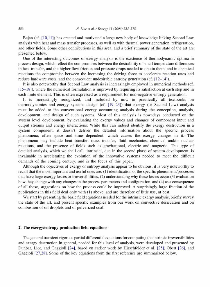
Bejan (cf. [10,11]) has created and motivated a large new body of knowledge linking Second Law
analysis with heat and mass transfer processes, as well as with thermal power generation, refrigeration,
and other fields. Some other contributions in this area, and a brief summary of the state of the art are
presented below.
One of the interesting outcomes of exergy analysis is the existence of thermodynamic optima in
process design, which reflect the compromises between the desirability of small temperature differences
in heat transfer, and the higher flow friction and pressure drops needed to obtain them, and in chemical
reactions the compromise between the increasing the driving force to accelerate reaction rates and
reduce hardware costs, and the consequent undesirable entropy generation (cf. [12–14]).
It is also noteworthy that Second Law analysis is increasingly employed in numerical methods (cf.
[15–18]), where the numerical formulation is improved by requiring its satisfaction at each step and in
each finite element. This is often expressed as a requirement for non-negative entropy generation.
It is increasingly recognized, and included by now in practically all textbooks on
thermodynamics and energy systems design (cf. [19–23]) that exergy (or Second Law) analysis
must be added to the conventional energy accounting analysis during the conception, analysis,
development, and design of such systems. Most of this analysis is nowadays conducted on the
system level development, by evaluating the exergy values and changes of component input and
output streams and energy interactions. While this can indeed identify the exergy destruction in a
system component, it doesn’t deliver the detailed information about the specific process
phenomena, often space and time dependent, which causes the exergy changes in it. The
phenomena may include heat transfer, mass transfer, fluid mechanics, chemical and/or nuclear
reactions, and the presence of fields such as gravitational, electric and magnetic. This type of
detailed analysis, which we shall call ‘intrinsic’, due in the second phase of system development, is
invaluable in accelerating the evolution of the innovative systems needed to meet the difficult
demands of the coming century, and is the focus of this paper.
Although the objectives of exergy or entropy analysis appear to be obvious, it is very noteworthy to
recall that the most important and useful ones are: (1) identification of the specific phenomena/processes
that have large exergy losses or irreversibilities, (2) understanding why these losses occur (3) evaluation
how they change with any changes in the process parameters and configuration, and (4) as a consequence
of all these, suggestions on how the process could be improved. A surprisingly large fraction of the
publications in this field deal only with (1) above, and are therefore of little use, at best.
We start by presenting the basic field equations needed for the intrinsic exergy analysis, briefly survey
the state of the art, and present specific examples from our work on convective desiccation and on
combustion of oil droplets and of pulverized coal.
2. The exergy/entropy production field equations
The general transient rigorous partial differential equations for computing the intrinsic irreversibilities
and exergy destruction in general, needed for this level of analysis, were developed and presented by
Dunbar, Lior, and Gaggioli [24], based on earlier work by Hirschfelder et al. [25], Obert [26], and
Gaggioli [27,28]. Some of the key equations from the first reference are summarized below.

N. Lior et al. / Energy 31 (2006) 553–578 557
The reversible entropy flux is
s Z3
TC
Xi
jiSi (1)
where
3 Z q CqR KX
i
jihi (2)
The exergy is defined as
a Z K CF C ðT KT0ÞS K ðP KP0Þv CX
i
ðmi Kmi0ÞUi (3)
where the terms on the right hand side of the equation are the kinetic, potential, thermal, strain, and
chemical exergy components, respectively. The transient rate of change of exergy of a fluid element
moving through the domain of interest is obtained by the substantial derivative, so Eq. (3) becomes
Da
DtZ
DK
DtC
DF
DtC
D½ðT KT0ÞS�
DtK
D½ðP KP0Þv�
DtC
DP
iðmi Kmi0ÞUi
� �Dt
(4)
To allow detailed calculation of the individual causes for exergy change, the terms in Eq. (4) were
decomposed into their basic components:
The transport of the kinetic exergy
ð5Þ
has seven components, due to: (i) shear stresses, (ii) work done by nonconservative body forces on the
species flux, (iii) reversible interconversion between kinetic and potential exergy, (iv) reversible
interconversion between kinetic and strain exergy, (v) irreversible conversion of kinetic exergy due to
friction (this part is converted to heat), (vi) irreversible conversion of nonconservative body force action
on the species flux, (vii) the irreversible portion of the potential to kinetic exergy conversion.
The transport of potential exergy,
ð6Þ
has three components, due to (viii) diffusion, (ix) reversible interconversion between kinetic and
potential exergy, (x) potential exergy change associated with reactions.
The transport of thermal exergy,
ð7Þ
has ten terms, due to (xi) heat diffusion, (xii) temperature changes, (xiii) heat conduction, the
reversible interconversions between (xiv) shear strain, (xv) normal strain, (xvi) nonconservative potential

N. Lior et al. / Energy 31 (2006) 553–578558
gradients, (xvii) body forces, (xviii) chemical reactions, (xix) chemical potential gradients, and (xx)
changes in the reference (dead state) temperature.
The transport of strain exergy
ð8Þ
has five terms, due to (xxi) net transport of strain exergy via normal stresses, (xxii) and (xxiii) are
reversible interconversions between normal strain and kinetic exergy, (xxiv) irreversible conversion of
strain exergy, and (xxv) changes in the reference (dead state) pressure.
The transport of chemical exergy:
ð9Þ
has 5 components due to (xxvi) chemical exergy diffusion, (xxvii) reversible interconversions with
thermal and/or strain exergy as can be understood from the Gibbs–Duhem Eq. (10)Xi
cidmi Z vdP KsdT ; (10)
(xxviii) and (xxix) irreversible conversion of chemical to thermal exergy by diffusion and chemical
reactions, respectively, and (xxx) changes in the reference (dead state) chemical potential.
The breakdown of exergy into such detailed components allows a most careful and detailed
examination of the source of irreversibility and exergy destruction. Many of the components may in
specific applications be negligible, but we can not know that before they are calculated. For example,
strain exergy may be negligible compared to thermal exergy in many cases, but will dominate in cases
where the velocity and velocity gradients are high while the thermal exergy is low.
While exergy is a very useful property, ultimate decisions on process improvement are most often
made based on economic considerations. In fact, lower exergy efficiencies are then acceptable if the
overall product cost is reduced thereby. The link between exergy analysis and economics, sometimes
named exergo-economics, is under continuous development (cf. [21]), but is based on component level
analysis. Proposals were made lately to assign an economic cost to local exergy values and to thus
evaluate the exergy cost fields as a continuum [29,30]. It is not difficult to add a cost multiplier to exergy
fields computed by the equations above, and it even may be of some use in evaluating some specific
problems, but, as opposed to thermodynamic and transport phenomena and properties, costs do not have
universal and commonly defined values. Furthermore, the assumption made that all components of the
local exergy have the same specific cost are too simplistic and usually incorrect. Consequently, the
proposed ‘Local Exergy Cost Theory’ should at best be regarded as local to the user and the specific
application, and not to spatial position.
3. The information needed for rigorous intrinsic exergy analysis
Observation of these equations shows that knowledge of the field parameters v (and hence t), P (and
hence also tn), T (and hence 3 and s), U (and hence also ji, m), of the state equations for the materials

N. Lior et al. / Energy 31 (2006) 553–578 559
used, to determine the thermophysical properties (r,m, S), and of the chemical reactions involved (to
determine l,Ri,ri) allows the computation of the exergy, exergy destruction, entropy, and entropy
generation fields. All of these field parameters are obtained from the solution of the full field and state
equations, consisting of the Navier-Stokes, energy, species conservation, entropy generation, and
thermodynamic properties equations, combined in a combustion process with the reaction kinetics
equations, all tightly coupled.
Naturally, at least an order of magnitude evaluation of the different components of exergy should be
performed as a first step, to determine whether they can be ignored or need to be calculated more
precisely.
4. Exergy analysis in heat transfer
Forced convection. Bejan [31] was perhaps the first to examine entropy generation in convective heat
transfer, noting that this leads to an optimization opportunity between the reduction of entropy
generation by using small temperature differences, and the pumping power needed. He developed
expressions for the optimal diameters of cylinders in internal and external convection, which minimize
entropy production. Several other studies followed along these lines, such as for external flows: across
cylinders with mixed forced an natural convection [32,33], and shear flows [34]; for internal flows
including examination of duct cross section shape [35,36] and swirling flows [37], and general
convection as well as convection-radiation interaction in porous media [38,39].
An appropriate application of the exergy analysis results is that by Ibanez et al. [40]. who analyzed
some simple cases to find that asymmetric cooling (more from one side than the other) leads to entropy
minimization.
Natural convection. Several authors have examined entropy generation in natural convection (cf.
[32,33,41,42]) and at the onset of natural convection [43].
5. Heat exchange
Intrinsic exergy (or entropy generation) analysis is very useful in determining the conditions at which
heat or mass exchange between bodies or streams can be performed with minimal entropy production. It
was found [44,45], that this minimum is attained in exchangers that allow constant entropy production in
all of their parts (equi-partition of entropy production), a condition approximated well by imposing equi-
partition of driving forces along the exchanger.
6. Exergy analysis in combined flow, heat and mass transfer
Notable are the papers [46,47].
An example: convective desiccation. An exergy analysis of the water vapor adsorption process in a
desiccant-air stream system, for laminar humid air flow over a desiccant flat bed, as well as in a
desiccant-lined channel, and for turbulent humid air flow in such a channel, for different turbulence

N. Lior et al. / Energy 31 (2006) 553–578560
intensities was conducted [48], and a brief summary of the major steps of the approach and of the major
results is given below.
The physical system considered (Fig. 1) is a flat silica-gel-packed desiccant bed of length L with a
uniform air stream passing over it in parallel.
6.1. Derivation of the flow exergy of the humid air stream
Using the system of Eqs. (1)–(4) Eq. (5)–(10) for this case produces the following equation expressing
the specific flow exergy on mass basis, (in kJ/kg)
ef ðx; yÞ Z To
cpa C ~Cðx; yÞcpv
1 C ~Cðx; yÞ
Tðx; yÞ
To
� �K1 K ln
Tðx; yÞ
To
� �� �CR ln
pðx; yÞ
po
� �
CRTo
1
1 C ~Cðx; yÞð1 C ~Cðx; yÞÞln
1 C ~Co
1 C ~Cðx; yÞ
� �C ~Cðx; yÞln
~Cðx; yÞ
~Co
� �� �(11)
Then, the total volume-average flow exergy (in kJ) is
E 000f Z
mf
Lðh KbÞ
ððhKbÞ
0
ðL
0ef ðx; yÞdxdy (12)
where mf is the mass of the moist air in the flow region and it is calculated by
mf Z rf ðh KbÞL (13)
where rf is the fluid (air-water vapor) density, h is the practical height, b is the desiccant bed thickness,
and L the bed length.
The local flow exergy Eq. (11) in kJ in the flow region is
Ef ðx; yÞ Z ef ðx; yÞmf ðx; yÞ (14)
Fig. 1. The physical model configuration for the flat desiccant bed.

N. Lior et al. / Energy 31 (2006) 553–578 561
From Eqs. (11)–(13), the volume-average thermo-mechanical and chemical components of the
exergy, E 000f ; th and E 000
f ; ch respectively, are
E 000f ;th Z
mf
Lðh KbÞ
!
ððhKbÞ
0
ðL
0To
cpa C ~Cðx; yÞcpv
1 C ~Cðx; yÞ
Tðx; yÞ
To
� �K1 K ln
Tðx; yÞ
To
� �� �CR ln
pðx; yÞ
po
� � dxdy
(15)
E 000f ; ch Z
mf
Lðh KbÞ
ððhKbÞ
0
ðL
0RTo
1
1 C ~C
!ðx; yÞ ð1 C ~Cðx; yÞÞln1 C ~C
1 C ~Cðx; yÞ
� �C ~Cðx; yÞln
~Cðx; yÞ
~Co
� �� �dxdy (16)
6.2. Derivation of the flow exergy of the water vapor in the desiccant bed
The amount of air that is adsorbed by desiccant is small compared to the amount of water vapor,
therefore the corresponding term in Eq. (9) can be assumed to be zero. Also, a term is added to represent
the heat of adsorption added to the system due to absorption rate m 000. Applying these conditions, the
specific flow exergy is
ef ;sðx; yÞ Z To cpv
~Cðx; yÞ
ð1 C ~Cðx; yÞÞ!
Tðx; yÞ
To
� �K1 K ln
T K ðx; yÞ
To
� �� �CR ln
pðx; yÞ
po
� �
CRTo
~Cðx; yÞ
ð1 C ~Cðx; yÞÞln
1 C ~Co
1 C ~Cðx; yÞ
� �C ln
~Cðx; yÞ
~Co
� �� �
KHlm
000ðx; yÞ
rf
� �$ 1 K
To
Tðx; yÞ
� �Dt (17)
where Hl is the adsorption heat, m 000 is the water adsorption rate, rf is the fluid density, and Dt is the time
step. Then, the total volume-average humid air exergy (in kJ) in the solid desiccant is
E 000f ;s Z
mf ;s
Lb
ðb
0
ðL
0ef ;sðx; yÞdxdy (18)
where mf,s is the mass of the fluid in the solid desiccant bed calculated by
mf ;s Z srf bL (19)
where s is the bed porosity.
The local flow exergy is also computed in kJ at any location in the solid desiccant bed from Eq. (17)
by
Ef ;sðx; yÞ Z ef ;sðx; yÞmf ;sðx; yÞ (20)

N. Lior et al. / Energy 31 (2006) 553–578562
From Eqs. (18)–(20), the volume-average thermo-mechanical, chemical, and adsorption heat in the
desiccant components of the exergy, respectively, are
E 000f ; th Z
mf ;s
Lb
!
ðb
0
ðL
0To cpv
~Cðx; yÞ
1 C ~Cðx; yÞ
Tðx; yÞ
To
� �K1 K ln
Tðx; yÞ
To
� �� �CR ln
pðx; yÞ
po
� � dxdy
(21)
E 000f ; ch Z
mf ;s
Lb
ðb
0
ðL
0RTo
~Cðx; yÞ
1 C ~Cðx; yÞln
1 C ~Co
1 C ~Cðx; yÞ
� �C ln
~Cðx; yÞ
~Co
� �� � dxdy (22)
E 0f ; ad Z
mf ;s
Lb
ðb
0
ðL
0
Hlm000ðx; yÞ
rf
1 KTo
Tðx; yÞ
� �Dt
dxdy (23)
It is noteworthy that the solid desiccant (without its vapor and air content) also has exergy, but it was
not considered in this study because it depends on the temperature primarily and its variation over the
small temperature range considered here is very small.
6.3. Computation and some results
The exergy was calculated from Eqs. (11), (15)–(17), and (21)–(23), using the velocity, temperature
and concentration field results in the humid air flow and the desiccant, described briefly above and in
more detail in [49].
The total exergy in the desiccant bed is about 25-fold lower than that in the humid air stream, and the
overall average exergy in the combined desiccant-air stream system is dominated by the average
chemical exergy in the air stream, so the values are nearly equal to those of the air stream. Typical results
are shown in Fig. 2: most of the water absorption takes place in the first cm or so, where the
corresponding release of heat of adsorption composes most of the exergy, and the chemical exergy
component dominates downstream, where the adsorption diminished significantly.
One of the exergy analysis results shown above indicates that the release of heat during the adsorption
process expends exergy without any benefit. As a matter of fact, the resulting heating of the air stream
being dehumidified is most often detrimental to the ultimate use of this air, such as in airconditioning
applications. Desiccant dehumidification analyzed here is generally an exergy efficient process, only !7% is destroyed due to unused heating.
Fig. 3 shows that the exergy for the laminar flow at tZ4 s is about 9% larger than that for turbulent
flow, due to the reduction in the water vapor concentration in the laminar flow model since the dominant
component in the desiccant-air system is the chemical component in the air stream (Eq. (16)). Therefore,
the overall average exergy decreases as the water vapor concentration increases with the time. The
exergy reduction for laminar flow is about 19.3%, and it is 26.5% for turbulent flow, as the time goes
from 0 to 1 s. While turbulence increases exergy reduction due to its dissipative nature, the main reason
for the observed exergy reduction here is the increased mass transport rates due to the turbulent flow.

Exergy components distribution along the bed inhumid air stream, y = 0.0035 m, t = 20 s
E, k
J
0.0000
0.0002
0.0004
0.0006
0.0008
0.0010
0.0012
Local chemical exergy componentLocal thermal exergy component
x, m0.10 0.11 0.12 0.13 0.14 0.15
(a)
Water vapor concentration in the air stream at y = 0.0035 m
C, k
g / k
g
0.006
0.008
0.010
0.012
0.014
0.016
0.018
0.020
0.022
x, m0.10 0.11 0.12 0.13 0.14 0.15
t = 2 st = 10 st = 20 s
(b)
Water adsorption rate in the desiccant bed, y = 0.003 m
x, m0.10 0.11 0.12 0.13 0.14 0.15
m ,
kg/m
3 .s
'''
– 4
– 2
0
2
4
6
8
10
12
14
16
t = 2 st = 10 st = 20 s
(c)
Fig. 2. (a) Exergy components, (b) water concentration, and (c) water adsorption rate distributions along the bed in the humid air
stream and the desiccant bed. uNZ0.1 m/s, ReLZ333, TNZ30 8C, CN Z0.0276 kg/kg, CbZ0.0075 kg/kg, ToZ25 8C, CoZ0.00992 kg/kg, mf,sZ1.9!10K5 kg, mf Z0.0028 kg, bZ0.00321 m, LZ0.05 m, hZ0.05 m, sZ0.1.
N. Lior et al. / Energy 31 (2006) 553–578 563
t, s
0 5 10 15 20
LaminarTurbulent
0.0016
0.0018
0.0020
0.0022
0.0024
0.0026
E ,
kj'''
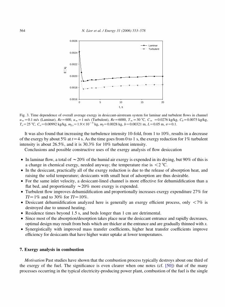
Fig. 3. Time dependence of overall average exergy in desiccant-airstream system for laminar and turbulent flows in channel
uNZ0.1 m/s (Laminar), ReZ600, uNZ1 m/s (Turbulent), ReZ6000, TNZ30 8C, CN Z0.0276 kg/kg, CbZ0.0075 kg/kg,
ToZ25 8C, CoZ0.00992 kg/kg, mf,sZ1.9!10K5 kg, mfZ0.0028 kg, bZ0.00321 m, LZ0.05 m, sZ0.1.
N. Lior et al. / Energy 31 (2006) 553–578564
It was also found that increasing the turbulence intensity 10-fold, from 1 to 10%, results in a decrease
of the exergy by about 5% at tZ4 s. As the time goes from 0 to 1 s, the exergy reduction for 1% turbulent
intensity is about 26.5%, and it is 30.3% for 10% turbulent intensity.
Conclusions and possible constructive uses of the exergy analysis of flow desiccation
† In laminar flow, a total of w20% of the humid air exergy is expended in its drying, but 90% of this is
a change in chemical exergy, needed anyway; the temperature rise is !2 8C.
† In the desiccant, practically all of the exergy reduction is due to the release of absorption heat, and
raising the solid temperature; desiccants with small heat of adsorption are thus desirable.
† For the same inlet velocity, a desiccant-lined channel is more effective for dehumidification than a
flat bed, and proportionally w20% more exergy is expended.
† Turbulent flow improves dehumidification and proportionally increases exergy expenditure 27% for
TIZ1% and to 30% for TIZ10%.
† Desiccant dehumidification analyzed here is generally an exergy efficient process, only !7% is
destroyed due to unused heating.
† Residence times beyond 1.5 s, and beds longer than 1 cm are detrimental.
† Since most of the absorption/desorption takes place near the desiccant entrance and rapidly decreases,
optimal design may result from beds which are thicker at the entrance and are gradually thinned with x.
† Synergistically with improved mass transfer coefficients, higher heat transfer coefficients improve
efficiency for desiccants that have higher water uptake at lower temperatures.
7. Exergy analysis in combustion
Motivation Past studies have shown that the combustion process typically destroys about one third of
the exergy of the fuel. The significance is even clearer when one notes (cf. [50]) that of the many
processes occurring in the typical electricity-producing power plant, combustion of the fuel is the single

N. Lior et al. / Energy 31 (2006) 553–578 565
largest contributor of exergy losses in power production. It is thus of great interest to determine the
magnitudes and causes of irreversibility in this process.
Past work summary The rigorous intrinsic exergy or entropy analysis, its analysis and some of the key
past papers, are those considering premixed flames stabilized above a flat-flame burner [51], diffusion
flames [52], droplet/spray combustion (cf. [53]), as well as couple of papers that dealt only with the
derivation of the equations [54,55]. Almost no practical conclusions about the use of the analysis for
process improvement were drawn.
Dunbar and Lior [56,57], have probably been the first to evaluate the primary causes for
irreversibility, using a somewhat heuristic finite increment exergy analysis method for a simple hydrogen
or methane combustor. With application to internal combustion engines in mind, Caton [58] investigated
the effects of temperature, pressure, and equivalence ratio for the combustion of octane-air mixtures in
adiabatic, constant volume combustion systems on the exergy destruction. He performed a simple global
control volume exergy analysis on the entire cylinder system, similar to the first step of the above-
described analysis by Dunbar and Lior [56,57]. He concluded that exergy losses decrease as the
combustion temperature increases (made possible by increasing the temperature of the inflowing
reactants), and as the equivalence ratio increases, and that they are fairly insensitive to the process
pressure.
8. Droplet and spray combustion
8.1. Background
Based on the solution of the field equations in spherico-symmetrical coordinates, Hiwase, Datta and
Som [59] and Datta and Som [60] have examined entropy generation and exergy destruction in droplet
(the former paper) and sprays (the latter) combustion. The velocity and species concentration fields for
the gas phase, and the temperature field for both the gas and for the droplet phases have been computed
from the numerical solution of the equations of conservation of mass, momentum and heat, and the rate
of entropy generation due to transport processes and chemical reaction in the gas phase has been
determined from the generalized entropy transport equation similar to those shown by Eqs (5)–(9). They
show time-integrated values of the exergy addition, irreversibility, and exergy efficiency, and found that,
in a typical diffusion-controlled droplet combustion process, in which the rate of chemical reaction is
much faster than the rates of diffusion of heat, mass and momentum, the entropy production rate due to
the chemical reaction is lower than that due to diffusion processes. Consistent with the findings of the
above-described simpler analyses, a low initial Damkohler number (as close as possible to its limiting
value for initiation of ignition) and a high free stream temperature were found to cause less destruction of
exergy. The field distribution of exergy destruction or entropy generation are not shown.
8.2. An example: exergy analysis of oil droplet combustion.
The droplet combustion process. Once the droplet is introduced in the hot atmosphere, its temperature
starts to rise and consequently some of it begins to vaporize at its surface. The initial vaporization rate is
slower because the droplet is cold, and it increases as the droplet heats up. Fuel vapor diffuses through
the hot gas until the criterion for the combustion reaction is met. At this point the reaction starts

N. Lior et al. / Energy 31 (2006) 553–578566
and the fuel is oxidized to form carbon dioxide and water. The combustion heat released raises the
temperature of the gas and of the droplet. Fig. 4 illustrates the problem. As the droplet continues
vaporizing, its radius decreases, thus originating a moving interface between the liquid droplet surface
and the outer, gaseous, domain. The process will continue until all the fuel is consumed.
A single spherical droplet of heptane was considered, and a model was developed and solved for the
transient mass, temperature, and velocity fields in the gas and droplet (with the temperature and
concentration dependence of the properties taken into account), which are then used for the Second Law
analysis of the problem. With that objective in mind, it was enough to use global kinetics for the
chemical reactions, assuming full completion of the reaction. The reaction rate is given by the commonly
used Arrhenius form equation
_u Z ArgYF
MWF
� �a rgYO2
MWO2
� �b
exp½KAe=ðRTgÞ� (24)
where YF and YO2 are the mass fraction of the fuel and oxygen, respectively.
Radiative transfer was ignored, as it complicates the analysis significantly, and the literature has
shown that the results are within 8% without it if no significant sooting occurs.
The finite element program FEMLAB was used for the solution, and a special computational scheme
was developed to account for the diminution of the droplet size as it evaporated. Convergence and grid-
independence of the numerical solution were proven, and the results were validated by comparison with
those available in the literature. The computed distribution of temperature with space and time is shown
in Fig. 5.
It shows clearly the ignition point (defined where TgO2000 K) and the flame location (denoted by the
gas temperature surface maxima), as well as the temperature distribution through the domain as a
function of time. It also shows that the high temperature zone is confined in a small region of r,
Fig. 4. A simplified sketch of the burning droplet. (Colour figure available online).

Fig. 5. The computed gas temperature as a function of distance and time for an n-heptane droplet of diZ(1)10K4 m, TliZ293 K
burning in air at TgiZ1073 K.
N. Lior et al. / Energy 31 (2006) 553–578 567
specifically for tO0.432 s and 0.002!r!0.09 m, indicating the high temperature-gradients affecting
the entropy generation.
Fig. 6, showing the gas temperature as a potential plot, complements Fig. 5 for easier visualization of
the evolution of flame position and of the droplet moving surface.
8.3. Exergy analysis
A primary objective of this analysis is to calculate the exergy efficiency 3 defined by
3 Z 1 KEd
Ein
(25)
Fig. 6. The computed gas temperatures distribution as a function of time for an n-heptane droplet of diZ(1)10K4 m, TliZ293 K
burning in air at TgiZ1073 K. (colour figure available online).

N. Lior et al. / Energy 31 (2006) 553–578568
where Ed is the exergy destruction in the defined control mass, and Ein is the exergy inflow into it. The
exergy analysis model control mass is shown in Fig. 7, and we first proceed to derive the equations
needed for computing Ein. The exergy balance for the control mass (CM) over this time interval dt is then
given by the equation
ECMðt CdtÞKECMðtÞ Z 1 KTo
Tg
� �dQCM K ðdWCM KpodVCMÞKdEd (26)
where ECM(tCdt)-ECM(t) is the overall exergy change in CM in the time interval [t, tCdt], The terms on
the r.h.s. of the equation represent the different contributions to this overall exergy change: (1-(To/Tg))
dQ is due to heat transfer between CM and the surroundings, (dWKpodV) is due to the work interactions
of CM with the surroundings, in which dW is the work done or received by the system and (podV) the
work necessary associated with changing the volume of CM, and dEd is the exergy destruction in CM.
The exergy change in the gas phase, CV, is obtained after some steps for this essentially isobaric
Fig. 7. Sketch of the control mass (CM) used for exergy analysis for tZt and tZtCdt, where R(t) is the droplet radius at tZt,
R(tCdt) is the droplet radius at tZtCdt, RN is the radius of the domain extent, h1: the surface between shaded region that
contains dmF and the CV, h2: the surface between CV and the external environment, dmF is the fuel mass contained in the
internal shaded region which length is dRF, dmO2 is the oxygen contained in the external shaded region which length is dRO2, dQ
is the amount of heat exchange with the surroundings, and dW is the amount of work interaction with the surroundings. (colour
figure available online).

N. Lior et al. / Energy 31 (2006) 553–578 569
systems, as
dEcv Z ðeh1dmF Ceh2
dmO2ÞKdEd (27)
where the first term on the r.h.s. is the exergy input to the above-defined CV that can be expressed in
integral form by the equation
_Ein Z _nF½eFchCeFth
CbO2ðeðO2Þch
CeðO2ÞthÞ� (28)
where _nF is the molar mass evaporation rate, eFchand eFth
are the fuel specific chemical and thermal
exergy and eðO2Þchand eðO2Þth
are the oxygen specific chemical and thermal exergy, respectively.
To use Eq. (25), it now remains necessary to compute the exergy destruction rate _Ed ZTo_S, where the
specific entropy generation rate due to the heat and mass transfer and the chemical reactions, based on
Eqs. (7)–(9) is,
_sp ZXng
jZ1
rgDg
vYj
vr
� �R
Yj
vYj
vr
� �C
1
T2g
kg
vTg
vr
� �2
C1
Tg
Xng
jZ1
sj rgDg
vYj
vr
� �vTg
vr
C1
Tg
Xng
jZ1
½hjðTgÞKTgsjðTg;PvjÞ�uj
( )(29)
In Eq. (29) the first term accounts for mass transfer ð_smÞ, the second is due to heat transfer ð_shÞ, the
third is the product of the coupling between heat and mass transfer ð_scÞ and the fourth takes into account
the production due to the chemical reaction ð_schÞ.
Integrating Eq. (29) over the gas phase control volume (R(t)!r!RN), gives the total entropy
generation rate at any instant in the CV as
_Sp Z 4p
ðRN
RðtÞ_spr2dr (30)
The total amount of exergy addition (Ein) and irreversibility or exergy destruction (Ed) from the start
(tZ0) till any later time t are then calculated by integrating, over that period of time, Eq. (28) for _Ein and
Eq. (30) (multiplied by To) for _Ed.
Fig. 8. Computed history of (a) (x) _Sch, (B) _Sm, (&) _Sh, and (^) _Sc and (b) _Sratio for an n-heptane droplet of diZ(1)10K4 m, TliZ293 K burning in air at TgiZ1073 K. (colour figure available online).

N. Lior et al. / Energy 31 (2006) 553–578570
To compare the magnitudes of the chemical reaction entropy generation relative to the other entropy
generation terms we define and calculate the ratio
_Sratio Z_Sch
ð _Sm C _Sh C _ScÞ(31)
Fig. 8a shows the contributions of each of the entropy terms composing Eq. (29), and Fig. 8b shows_Sratio, as a function of time. All the individual terms in the equations used to describe the entropy
generation are presented in detail further below.
As the droplet evaporation proceeds, the total entropy generation increases due to the increase in the
concentration gradients and the increasing rate of the chemical reaction in the gas phase caused by the
higher fuel concentration that has been diffused from the droplet, as shown in Fig. 8a. Only _Sh decreases
during the pre-combustion stage of the process [(&) curve in Fig. 8a] due to the diminution of the heat
gradient in this period resulting from the progressive rise of the droplet temperature while the gas phase
temperature does not vary significantly (Figs. 5 and 6). Once combustion is attained (at tZ0.432 s), the
chemical reaction entropy component becomes the main contributor to the total entropy generation. The
Fig. 9. The computed (a) _sch as a function of position and time, (b) _sch evolution in time, and (c) Contour plot for _sch; for an
n-heptane droplet of diZ(1)10K4 m, TliZ293 K burning in air at TgiZ1073 K. (colour figure available online).

N. Lior et al. / Energy 31 (2006) 553–578 571
significance of the dominant role of the chemical component is better seen in Fig. 8b. It shows variation
of _Sratio with respect to time. Fig. 9 shows the computed chemical entropy generation during the droplet
life. As shown in Fig. 8, the chemical entropy generation dominates the irreversibility production once
combustion is attained and therefore Fig. 9 gives a good indication of the evolution of the local
irreversibility generation during the combustion process. The rapid increase that the chemical entropy
generation ð_schÞ exhibits when and where the combustion is triggered is clearly seen, and explained in
more detail below. Another observation is that the peak value of the chemical entropy generation follows
the flame evolution shown in Figs. 5 and 6.
As described by Eq. (29), the chemical entropy generation term is a function of the gas temperature
(Tg) and the reaction rate ð _uÞ. The maximum of ð_schÞ is obtained at tZ0.4356 s, which is about 3.4 ms
after the criterion to achieve ignition (TgO2000 K) is met. The maximum of _sch occurred at the same
time that the maximum of _u is reached, but about 5.4 ms before the maximum Tg is reached. This
indicates that the maximum of _sch is more influenced by the reaction rate than by the gas temperature
profile. The second most important contributor to irreversibility generation is _Sh. From Eq. (29) we see
that _sh depends on (Tg)K1, kg, and (PTg)2, and further analysis of these terms has shown that kgPTg has
the dominant influence, interestingly in important part because of the variation of kg with temperature.
In an attempt to reduce the irreversibility due to the temperature gradients, the initial environment
temperature was increased by 100 K, from 1073 to 1173 K, resulting in an increase of 3.7% in 3.
_sm defined in Eq. (29) has the terms _sm1ZPng
jZ1 rgDgVYj that represents the entropy generation due to
species diffusion, and
_sm2 ZXng
jZ1
R
Yj
VYj
that represents entropy generation due to concentration gradients, where the summations are for all the
species present in the gas phase. The latter term was found to be 108-fold larger than the former, in
determining the value of _sm.
8.4. Exergy Input
It is of interest to now examine the exergy input ð _EinÞ behavior and influence on 3. It is calculated
using Eq. (28).
Examining Eq. (28) and realizing that the term ðeFthCbO2
eðO2ÞchÞ is nearly constant during the process,
it is obvious that ð _EinÞ depends primarily on the fuel evaporation rate _nF . First, there is a moderate
increase correspondent to initial fuel evaporation prior to combustion, then a rapid increases due to
strong heating resulting from the ignition, and finally a period of almost constant decrease due to the
droplet shrinkage with a slope change at the end of the droplet life that is an indication of the beginning
of the extinction process.
One way to consider affecting the 3 is by slowing down the reaction. This was attempted in the
analysis by reducing the pre-exponential factor A in the kinetics Eq. (24) to 1/3 of that in the base case
value. It was found that the duration of the high entropy production during the combustion reaction is
then shorter for the case where the reaction rate is slower, while the magnitude of the entropy production
rate remains basically the same, but, importantly, the droplet life is much longer for this case, tZ1.6605 s, as compared to the other cases evaluated (tZ1.233 s for the base-case and tZ0.9315 s for

Fig. 10. Exegy inflow ð _EinÞ as a function of time for an n-heptane droplet of diZ(1)10K4 m, TliZ293 K burning in air at TgiZ1073 K.
N. Lior et al. / Energy 31 (2006) 553–578572
TgiZ1173 K). Consequently the cumulative effect of _Ed is bigger, counteracting in this way the lower
instantaneous entropy values and resulting in a lower 3 value.
Since the total magnitude of _SP is similar for the evaluated cases for their pre- and post- combustion
periods, and taking into consideration that Ein will always be the same at the end of the droplet life
(because the fuel volume is the same), it is concluded that the duration of the droplet combustion is a key
factor in the value of 3, and its reduction may increase 3. To reduce the duration of the droplet
combustion, the reaction rate was accelerated by increasing the oxygen mole fraction in the air from 0.23
to 0.70, and this case was called ‘fast combustion’.
Fig. 10 shows _SP for all cases evaluated. The time-evolution of the instantaneous value of the second
law efficiency _is similar for all the cases, but the period for the ‘fast combustion’ case is much shorter:
the combustion of the droplet lasts only 0.459 s as compared with 1.233 s in the base case. The pre-
combustion evaporation period for this case is only 18.3% of the droplet life. The total 2 was 73.2%, a
7% improvement of over the base case. The improvement in the efficiency is obtained despite the higher
instantaneous entropy generation values during combustion in this case.
Table 1 summarizes the main results for the cases evaluated in this work.
Table 1
Summary of results obtained in the sensitivity analysis
Case name Conditions Ignition delay
time (s)
Exergy dest-
ructionEd (J)
2d Law Effi-
ciency 3 (%)Tgi (K) YO2i (in air) A in _u Eq. (22)
Base-case 1073 0.23 A 0.432 5.140 68.4
High-temp-
erature
1173 0.23 A 0.092 4.749 70.9
Reduced _u 1073 0.23 A/3 1.195 5.165 68.2
Fast- combust. 1073 0.70 A 0.084 4.409 73.2

Fig. 11. Computed _SP as a function of time for an n-heptane droplet of diZ(1)10K4 m, TliZ293 K burning in air at TgiZ1073 K
(%); TgiZ1173 K (B); 1/3 of pre-exponential factor (A) in Arrhenius Eq. (2.2) (,); fast-combustion case (x). (colour figure
available online).
N. Lior et al. / Energy 31 (2006) 553–578 573
9. An example: exergy analysis in a pulverized coal combustion process
In the course of research of a novel low NOx pulverized coal combustor concept where the flame
is stabilized by radiation and conduction from and through the combustor walls, respectively
Fig. 12. The computed temperature distribution in the RCSC. The flow is downward. Coal feed rateZ0.2 g/s, equilibrium
air/fuel ratioZ1.10, inlet air/fuel temperatureZ573 K. (colour figure available online).

Fig. 13. The thermomechanical exergy distribution in the RCSC. Same conditions as in Fig. 12. (colour figure available online).
N. Lior et al. / Energy 31 (2006) 553–578574
(the Radiatively/Conductively-Stabilized Pulverized Coal Combustor (RCSC), Kim and Lior [61,62]), a
rigorous intrinsic exergy analysis was also performed, and details can be found in [63]. The solution
gives the 3-dimensional distribution of gas, particle and wall temperature, and radiation intensity, gas
and particle velocity, and species concentrations. As stated earlier, this allows the determination of the
spatial distribution of all of the components of exergy, using Eqs. (5)–(9).
At first, an order of magnitude analysis determined that the potential, strain, amd kinetic exergy
components can be ignored, leaving only the thermal and chemical components.
Fig. 14. The chemical exergy distribution in the RCSC. Same conditions as in Fig. 12. (colour figure available online).

Fig. 15. The total exergy distribution in the RCSC. Same conditions as in Fig. 12. (colour figure available online).
N. Lior et al. / Energy 31 (2006) 553–578 575
The gas species here are CO2, CO, NO, NH, H2O, H2, O2, H, OH, N2, HNO, O, N, HCN, NH3.
Among these species, the mole concentration of NH, H, O, OH, N is less than 0.1% of the total gases, and
thus their effect on the thermomechanical and chemical exergy can be ignored.
The computed temperature field in the combustor, for the gas and the coal particles (separately) is
shown in Fig. 11. The primary flame region is the meniscus-shaped area about 1/3 down from the top.
Among other things, one can observe the gradual heating of the gas and the coal particles, by convection
and radiation from the combustor walls, the narrowness of the flame zone (which is an objective of this
combustor) and the radial temperature drop due to wall heat losses. Since the thermal exergy is one of the
major exergy components, the temperature field is an important indicator of the magnitude of this exergy
component Fig. 12.
The thermomechanical, chemical, and total exergy distribution fields are shown in Figs. 13, 14, and
15, respectively (in these figures the direction perpendicular to the axial flow direction of the combustor,
Z/R is the radial one, r/R; the numbers 1 along these axis represent r/RZ0 and Z/RZ0). Some of the
conclusions from observing these distributions are (i) the thermal exergy follows rather closely the
temperature field, (ii) the chemical exergy starts decreasing when the volatiles start burning, and then
decreases precipitously when the char starts burning, and (iii) the total exergy rises to a peak at the
upstream face of the flame front where the temperature is high due to thermal feedback yet the chemical
exergy has not been completely used up yet.
For the conditions of this study, about 30% of the original fuel exergy is destroyed in the combustion.
Over 90% of exergy destruction takes place in the thin flame zone, and less than 10% destroyed
downstream of the flame zone, the latter due to the temperature drop and heat loss due to the radiative
and convective transport to the surrounding wall and exit. So far, only the effects of inlet air temperature,
in the range of 573–973 K, were investigated; increasing it tended to slightly decrease the exergy
efficiency, in part because of the increased heat losses.
N. Lior et al. / Energy 31 (2006) 553–578576
While one may draw many conclusions from this analysis about possible ways to improve the
exergetic efficiency in this combustor, a couple are already evident. One is the effectiveness of thermal
feedback: the thermal exergy is raised by this feedback upstream of the flame front to about 1/3 of its
maximal value. Another is the possibility of the existence of an optimal combustor exit location for the
mixture, where the exergy is higher than the one shown here and yet the reactions were completed to
satisfactory extent.
Acknowledgements
The work on the exergy analysis in the coal combustor was performed with the assistance of F. Xiong,
and partially supported by a grant from the University Coal Research Program of the US Department of
Energy, National Energy Technology Laboratory.
References
[1] Gouy G. About available energy (in French). J Physique II 1998;8:501–18.
[2] Stodola A. The cyclic process of the gas engine (in German). Z. VDI 1898;32(38):1086–91.
[3] Gibbs JW. Collected Works, 1. New Haven: Yale University Press; 1948.
[4] Keenan JH. A steam chart for second law analysis. Mech Eng 1932;54:195–204.
[5] Keenan JH. Thermodynamics. New York: Wiley; 1941.
[6] Bosnjakovic F. Fight against irreversibilities (in German). Arch Warmewirt 1938;19(1):1–2.
[7] Rant Z. Exergy, a new word for technical available work (in German). Forsch Ing Wes 1956;22(1):36–7.
[8] Denbigh KG. The second-law efficiency of chemical processes. Chem Eng Sci 1956;6(1):1–9.
[9] Leites, I.L., Sama, D.A., Lior, N., The theory and practice of energy saving in the chemical industry: some methods for
reducing thermodynamic irreversibility in chemical technology processes. Energy 2003; 28(1): 55-97, with Corrigendum,
Energy 2004; 29(2) 301-304.
[10] Bejan A. The thermodynamic design of heat and mass transfer processes and devices. Heat and Fluid Flow 1987;8:
258–76.
[11] Bejan A. Entropy generation minimization: the method of thermodynamic optimization of finite-size systems and finite-
time processes. Boca Raton, FL: CRC Press; 1996.
[12] Kjelstrup Ratkje S, De Swaan Arons J. Denbigh revisited: reducing lost work in chemical processes. Chem Eng Sci 1995;
50:1551–60.
[13] Kjelstrup S, Sauar E, Bedeaux D, van der Kooi H. Driving force distribution for minimum lost work in chemical reactors
close to and far from equilibrium. 1. Theory Ind Eng Chem Res 1999;38:3046–50.
[14] Kjelstrup S, Island TV. Driving force distribution for minimum lost work in chemical reactors close to and far from
equilibrium 2. Oxidation of SO2 Ind Eng Chem Res 1999;38:3051–5.
[15] Oleinik OA. Discontinuous solutions of nonlinear differential equations. AMS Translation Series 2 1957;26:95–172
(Providence, R.I.: American Mathematical Society).
[16] Harten A, Hyman JM, Lax PD. On finite difference approximation and entropy conditions for shocks. Communications on
Pure and Appl Math 1976;29:297–322.
[17] Camberos JA. Nonlinear time-step constraints based on the second law of thermodynamics. J Thermophys Heat Transfer
2000;14(3):435–49.
[18] Naterer GF, Camberos JA. Entropy and the second law fluid flow and heat transfer simulation. J Thermophysics 2003;
17(3):360–71.
[19] Szargut J, Morris DR, Steward FR. Exergy analysis of thermal, chemical and metallurgical processes. New York:
Hemisphere; 1988.

N. Lior et al. / Energy 31 (2006) 553–578 577
[20] Moran, M.J., Availability analysis—a guide to efficient energy use (corrected edition). New York: ASME, 1989.
[21] Bejan A, Tsatsaronis G, Moran M. Thermal design and optimization. New York: Wiley; 1996.
[22] Bejan. Advanced engineering thermodynamics. 2nd ed. New York: Wiley; 1997.
[23] Moran MJ, Shapiro NH. Fundamentals of engineering thermodynamics. 5th ed. Hoboken, NJ: Wiley; 2004.
[24] Dunbar WR, Lior N, Gaggioli RA. The component equations of energy and exergy. ASME J Energy Resour Technol
1992;114:75–83.
[25] Hirschfelder JO, Curtiss F, Bird RB. Molecular theory of gases and liquids. New York: Wiley; 1954.
[26] Obert EF. Concepts of Thermodynamics. New York: McGraw-Hill; 1960.
[27] Gaggioli RA. The concept of available energy. Chem Eng Sci 1961;16:87–96.
[28] Gaggioli RA. The concepts of thermodynamic friction, thermal available energy, chemical available energy, and thermal
energy. Chem Eng Sci 1962;17(7):523–30.
[29] Chen Q, Wang S, Yin Q, Hua B. Theoretical reserach on the transfer equation of exergy cost. In: Tsatsaronis G, Moran M,
editors. ECOS ’02 Conference, Berlin, Germany. Institute for Energy Engineering, vol. 1. Berlin: Technische Universitat;
2002. p. 207–14.
[30] Rangel, V.H., Uson, S., Valero, A., Cortes, C., Local exergy cost theory. Paper IMECE2004-61192 in Proc. IMECE04,
2004 ASME Int. Mech. Engng Congress and Exposition, Anaheim, CA, USA. ASME NY: 2004.
[31] Bejan A. A study of entropy generation in fundamental convective heat transfer. J Heat Transfer 1979;101:718–25.
[32] Abu-Hijleh B. Entropy generation in laminar convection from an isothermal cylinder in cross flow. Energy 1998;23:
851–7.
[33] Abu-Hijleh BAK, Heilen WN. Entropy generation due to laminar natural convection over heated rotating cylinder. Int
J Heat Mass Transfer 1999;42:4225–33.
[34] Kock F, Herwig H. Local entropy production in turbulent shear flows: a high-Reynolds number model with wall functions.
Int J Heat Mass Transfer 2004;47:2205–15.
[35] Ratts EB, Raut AG. Entropy generation minimization of fully developed internal flow with constant heat flux. J Heat
Transfer 2004;126:656–9.
[36] Oztop HK, Sahin AZ, Dagtekin I. Entropy generation through hexagonal cross-sectional duct for constant wall
temperature in laminar flow. Int J Energy Res 2004;28:725–37.
[37] Mukherjee F, Biswas G, Nag PK. Second law analysis of heat transfer in swirling flow through a cylindrical duct. J. Heat
Transfer 1987;109:308–13.
[38] Mahmud S, Fraser RA. The second law analysis in fundamental convective heat transfer problems. Int J Thermal Sci 2003;
42:177–86.
[39] Mahmud S, Fraser RA. Mixed convection-radiation interaction in a vertical porous channel: entropy generation. Energy
2003;28:1557–77.
[40] Ibanez G, Cuevas S, Lopez de Haro M. Minimization of entropy generation by asymmetric convective cooling. Int J Heat
Mass Transfer 2003;46:1321–8.
[41] Abu-Hijleh B, Abu-Qudais M, Abu Nada A. Numerical prediction of entropy generation due to natural convection from a
horizontal cylinder. Energy 1999;24:327–33.
[42] Abu-Hijleh B. Natural convection heat transfer and entropy generation from a horizontal cylinder with baffles. J Heat
Transfer 2000;122:679–92.
[43] Magherbi M, Abassi H, Ben Brahim A. Entropy generation at the onset of natural convection. Int. J. Heat Mass Transfer
2003;46:3441–50.
[44] Tondeur D, Kvaalen E. Equipartition of entropy production. An optimal criterion for transfer and separation processes. Ind
Eng Chem Res 1987;26:50–6.
[45] Johanessen E, Nummedal L, Kjelstrup S. Minimizing the entropy production in heat exchange. Int J Heat Mass Trasnfer
2002;45:2649–54.
[46] San JY, Worek WM, Lavan Z. Entropy generation in combined heat and mass transfer. Int J Heat Mass Transfer 1987;30:
1359–68.
[47] Poulikakos DM, Johnson JM. Second law analysis of combined heat and mass transfer phenomena in external flow.
Energy 1989;14:67–73.
[48] Lior N, Al-Sharqawi HS. Exergy analysis of flow dehumidification by solid desiccants. Energy 2005;30(6):915–31.

N. Lior et al. / Energy 31 (2006) 553–578578
[49] Al-Sharqawi HS, Lior N. Conjugate computation of transient flow and heat and mass transfer between humid air and
desiccant plates and channels, paper IMECE2003-41890, Proceedings of IMECE’03, 2003 ASME International
Mechanical Engineering Congress and Exposition, Washington, DC, Nov. 16–21, 2003; New York: ASME.
[50] Gaggioli RA, Yoon,JJ, Patulski SA, Latus, AJ, Obert EF. (1975). Pinpointing the real inefficiencies in power plants and
energy systems. In: Gaggioli RA, editors. Proc Amer Power Conf Washington, DC; p. 671–9.
[51] Arpaci V, Selamet A. Entropy production in flames. Combust Flame 1988;73:251–9.
[52] Stanciu D, Isvoranu D, Marinescu M, Gogus Y. Second law analysis of diffusion flames. Int J Appl Thermodyn 2001;4(1):
1–18.
[53] Puri IK. Second law analysis of convective droplet burning. Int J Heat Mass Transfer 1992;35:2571–8.
[54] Beretta GP, Keck JC. Energy and entropy balances in a combustion chamber: analytical solution. Comb Sci Technol 1983;
30:19–29.
[55] Teng H, Kinoshita CM, Masutani SM, Zhou J. Entropy generation in multicomponent reacting flows. ASME J Energy
Resour Technol 1998;120:226–32.
[56] Dunbar WR, Lior N. A Breakdown of the exergy losses in combustion, Proc. World Energy Conf., Florence, Italy. Oxford:
Pergamon Press; 1990 p. 347–58.
[57] Dunbar WR, Lior N. Sources of combustion irreversibility. Combust Sci Technol 1994;103:41–61.
[58] Caton JA. On the destruction of availability (exergy) due to combustion processes-with specific application to internal-
combustion engines. Energy 2000;25:1097–117.
[59] Hiwase SD, Datta A, Som SK. Entropy balance and exergy analysis of the process of droplet combustion. J Phys D: Appl
Phys 1998;31(13):1601–10.
[60] Datta A, Som SK. Thermodynamic irreversibilities and second law analysis in a spray combustion process. Comb Sci
Technol 1999;142:29–54.
[61] Kim, C., Lior, N. Combined-mode conjugate heat transfer in a radiatively/conductively-stabilized pulverized coal
combustor, ASME Paper 93-WA/HT-37, ASME Winter Annual Meeting, 1993, New Orleans, LA.
[62] Kim C, Lior N. A numerical analysis of NOx formation and control in radiatively/conductively-stabilized pulverized coal
combustors. J Chem Eng 1998;71:221–31.
[63] Lior, N., Irreversibility in combustion, invited keynote paper, Proc. ECOS ’01: Efficiency, Costs, Optimization,
Simulation and Environmental Aspects of Energy Systems, Istanbul, Turkey. 1, (2001) 39-48.