review on scada system in pakistan
TRANSCRIPT

1
Supervisory Control & Data Acquisition System (SCADA)
And
Energy Management System (EMS)
Supervised By:
Prof.Dr. Tahir Nadeem Malik
Submitted By:
SALMAN ZAFAR
12F-MS-EE-37
Energy & Electrical power System Group: Power System Laboratory
Electrical Engineering Department
University of Engineering & Technology, Taxila.
2
Table of Contents
CHAPTER NO. 1: SCADA SYSTEM ________ ERROR! BOOKMARK NOT DEFINED.
1.0 Introduction ________________________________________________________3
1.1 Basic Architecture of SCADA System ___________________________________4
1.2 The Evolution of EMS/SCADA ________________________________________4
1.3 Difference Between SCADA and DCS ___________________________________5
CHAPTER NO. 2: STATUS OF SCADA SYSTEM IN PAKISTAN ___________________7
2.0 Introduction ________________________________________________________7
2.1 Power System Automation ____________________________________________7
2.2 SCADA System for National Power Control Centre ________________________8
2.3 Miscellaneous information about SCADA (NPCC) ________________________13
2.4 Suggestions for improvement in the status of P re se n t S C AD A S ys t e m ____14
CHAPTER NO. 3: RECENT RESEARCH PAPERS ON SCADA SYSTEM____________16
CHAPTER NO. 4: SCADA SYSTEM IN FUTURE _______________________________18
4.0 Interoperability ____________________________________________________18
4.1 The Promise of Wireless Sensor Networking _____________________________18
4.2 Extensibility ______________________________________________________18
4.3 What needs to be done? ______________________________________________19
3
CHAPTER NO.01 SCADA SYSTEM
1.0 INTRODUCTION
The acronym SCADA stands for Supervisory Control and Data Acquisition. In
reality, the primary purpose of SCADA is to monitor, control and alarm plant or regional
operating systems from a central location. As the name indicates, it is not a full control
system, but rather focuses on the supervisory level. As such, it is a purely software package
that is positioned on top of hardware to which it is interfaced, in general via Programmable
Logic Controllers (PLCs), or other commercial hardware modules. SCADA systems are
combination of computers, controllers, instruments; actuators, networks and interfaces that
manage the control of automated and allow analysis of those system by data collection and
processing.
What Makes up SCADA System? There are three main elements to a SCADA
system, various RTU's (Remote Telemetry Units), communications and an HMI (Human
Machine Interface).
Each RTU effectively collects information at a site, while communications bring that
information from the various plant or regional RTU sites to a central location, and
occasionally returns instructions to the RTU.
The HMI displays this information in an easily understood graphics form, archives the
data received, transmits alarms and permits operator control as required.
Communication within a plant will be by data cable, wire or fiber-optic, while regional
systems most commonly utilize radio. The HMI is essentially a PC system running powerful
graphic and alarm software programs.
Why is SCADA so Popular? The major attraction of SCADA to a municipality is the
ability to significantly reduce operating labor costs, while at the same time actually improve
plant or regional system performance and reliability. Information gathering within a plant no
longer requires personnel to spend time wandering all over the site, and correspondingly the
frequency of field site inspections required in a regional system can be minimized.
Costly after-hours alarm call-outs can often be avoided since a SCADA system will
indicate the nature and degree of a problem, while the ability to remotely control site
equipment may permit an operator at home to postpone a site visit till working hours.
SCADA based alarming is also very reliable since it is in-house and tied directly to process
control.
A significant feature of a SCADA system, often not fully appreciated, is the trending
of data and nothing comes close for speed and ease of operation. When graphically displayed,
accumulated operating data often will indicate a developing problem, or an area for process
improvement. Reports can easily be generated from this data utilizing other common
software programs. It should be appreciated that while a SCADA system is often complex to
configure - it is extremely easy to operate!
4
1.1 Basic Architecture of SCADA System
There are five phases to creating a functional SCADA system:
Phase 1
This is the design of the system architecture. This includes the all-important
communication system, and with a regional system utilizing radio communication often
involves a radio path survey. Also involved will be any site instrumentation that is not
presently in existence, but will be required to monitor desired parameters.
Phase 2
The SUPPLY of RTU, communication and HMI equipment, the latter consisting of a
PC system and the necessary powerful graphic and alarm software programs.
Phase 3
This includes the programming of the communication equipment and the powerful
HMI graphic and alarm software programs.
Phase 4
This includes the INSTALLATION of the communication equipment and the PC
system. The former task is typically much more involved.
Phase 5
This includes the COMMISSIONING of the system, during which communication
and HMI programming problems are solved, the system is proven to the client, operator
training and system documentation is provided.
1.2 SCADA and EMS
An Energy management system (EMS) is a system of computer-aided tools used by
operators of electric utility grids to monitor, control, and optimize the performance of the
generation and/or transmission system. The monitor and control functions are known as
SCADA; the optimization packages are often referred to as "advanced applications".
The computer technology is also referred to as SCADA/EMS or EMS/SCADA. In
these respects, the terminology EMS then excludes the monitoring and control functions, but
more specifically refers to the collective suite of power network applications and to the
generation control and scheduling applications.
SCADA/EMS/GMS (supervisory control and data acquisition/Energy Management
System/Generation Management System) supervise controls, optimize and manage
generation and transmission systems. SCADA/DMS (Distribution Management System)
performs the same functions for power distribution networks.
Both systems enable utilities to collect, store and analyze data from hundreds of
thousands of data points in national or regional networks, perform network modeling,
5
simulate power operation, pinpoint faults, preempt outages, and participate in energy trading
markets.
Manufacturers of EMS also commonly supply a corresponding dispatcher training
simulator (DTS). This related technology makes use of components of SCADA and EMS as a
training tool for control centre operators. It is also possible to acquire an independent DTS
from a non-EMS source such as EPRI.
Energy management systems are also often commonly used by individual commercial
entities to monitor, measure, and control their electrical building loads. Energy management
systems can be used to centrally control devices like HVAC units and lighting systems across
multiple locations, such as retail, grocery and restaurant sites. Energy management systems
can also provide metering, submetering, and monitoring functions that allow facility and
building managers to gather data and insight that allows them to make more informed
decisions about energy activities across their sites.
1.3 Difference between SCADA and DCS
The goals of DCS and SCADA are quite different. It is possible for a single system to
be capable of performing both DCS and SCADA functions, but few have been designed with
this in mind, and therefore they usually fall short somewhere. It has become common for
DCS vendors to think they can do SCADA because the system specifications seem so similar,
but a few requirements paragraphs about data availability and update processing separates a
viable SCADA system from one that would work OK if it weren't for the real world getting in
the way.
DCS is process oriented: it looks at the controlled process (the chemical plant or
whatever) as the centre of the universe, and it presents data to operators as part of its job.
SCADA is data-gathering oriented: the control centre and operators is the centre of its
universe. The remote equipment is merely there to collect the data--though it may also do
some very complex process control!
A DCS operator station is normally intimately connected with its I/O (through local
wiring, Field Bus, networks, etc.). When the DCS operator wants to see information he
usually makes a request directly to the field I/O and gets a response. Field events can directly
interrupt the system and advise the operator.
SCADA must operate reasonably when field communications have failed. The
'quality' of the data shown to the operator is an important facet of SCADA system operation.
SCADA systems often provide special 'event' processing mechanisms to handle conditions
that occur between data acquisition periods.
There are many other differences, but they tend to involve a lot of detail. The
underlying points are:
SCADA needs to get secure data and control over a potentially slow, unreliable
communications medium, and needs to maintain a database of 'last known good values' for
6
prompt operator display. It frequently needs to do event processing and data quality
validation. Redundancy is usually handled in a distributed manner.
DCS is always connected to its data source, so it does not need to maintain a database
of 'current values'. Redundancy is usually handled by parallel equipment, not by diffusion of
information around a distributed database.
These underlying differences prompt a series of design decisions that require a great
deal more complexity in a SCADA system database and data-gathering system than is usually
found in DCS. DCS systems typically have correspondingly more complexity in their
process-control functionality.
7
CHAPTER NO.02 Status of SCADA System in Pakistan
2.0 Introduction
The ability to perform operations at an unattended location from an attended station or
operating center and to have a definite indication that the operations have been successfully
carried out can provide significant cost saving in the operation of a power system. This is
exactly what we try to achieve through the SCADA (an acronym for Supervisory
Control and Data Acquisition) system. A formal definition of SCADA system, as
recommended by IEEE, is “A collection of equipment that will provide an operator at a
remote location with sufficient information to determine the status of p a r t i c u l a r
e q u i p m en t o r a p roc es s a nd c a u se a c t i on s to t ak e p la c e r e ga rd i n g th a t
equipment or process without being physically present”. Power system vendors
are following a trend to make devices smarter so they can create and
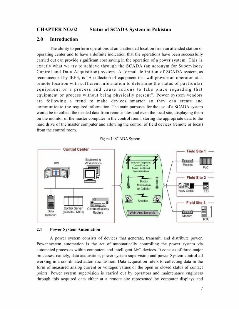
communicate the required information. The main purposes for the use of a SCADA system
would be to collect the needed data from remote sites and even the local site, displaying them
on the monitor of the master computer in the control room, storing the appropriate data to the
hard drive of the master computer and allowing the control of field devices (remote or local)
from the control room.
Figure-1: SCADA System
2.1 Power System Automation
A power system consists of devices that generate, transmit, and distribute power.
Power system automation is the act of automatically controlling the power system via
automated processes within computers and intelligent I&C devices. It consists of three major
processes, namely, data acquisition, power system supervision and power System control all
working in a coordinated automatic fashion. Data acquisition refers to collecting data in the
form of measured analog current or voltages values or the open or closed status of contact
points .Power system supervision is carried out by operators and maintenance engineers
through this acquired data either at a remote site represented by computer displays and
8
graphically wall displays or locally, at the device site, in the form of front-panel displays and
laptop computers. Control refers to sending command messages to a device to operate I&C
(A collection of devices that monitor, control and protect the system is referred
as instrumentation and control (I&C) system) and power system devices.
2.1.1 National Power Control Centre
The National Power Control Centre located in Islamabad was inaugurated by Mr.
Ghulam Ishaq Khan, President of Pakistan on 20th January, 1990.It envisages
implementation of the modern computerized load dispatch facilities for operating WAPDA's
power system, by setting up of one National Power Control Centre (NPCC) at Islamabad and
two Regional Control Center at Islamabad and Jamshoro for northern and southern parts of
the network respectively. The main functions of this Power Control Centre are given below:
1. Real time control of the load generation, power exchanges, voltage regulation,
generation reserves and the transmission network.
2. Follow up of efficiency, fault analysis, compilation of statistics, reporting and
accounting.
3. Short and long term planning, including load prediction, and generators,
schedules, power balance planning, coordination of unit out-ages for maintenance
and planning for reserves.
4. Arranging of routine and emergent short down son generators, transmission
lines, power transformers and other components of the power system.
Above functions are to be performed by the Power Control System with the help of
hi-tech computers and other modern facilities for power supervisory control, data
acquisition and energy management. Under this project all 500 KV, 220 KV and some of the
important 132 KV grid stations have been connected to the SCADA (Supervisory Control
and Data Acquisition) system.
2.2 SCADA System for National Power Control Centre
Present status of SCADA system at NPCC, its components, and its working etc. is
given below:
2.2.1 Data acquisition system
Data acquisition in SCADA used to access and control information or data from the
equipment being controlled and monitored. The data accessed are then forwarded onto at
elementary system ready for transfer to the different sites. They can be analog and digital
information gathered by sensors, such as flow meter, ammeter, etc. It can also be data to
control equipment such as actuators, relays, valves, motors, etc. SCADA computers at
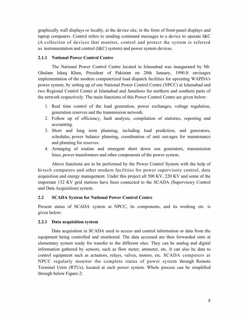
NPCC regularly monitor the complete status of power system through Remote
Terminal Units (RTUs), located at each power system. Whole process can be simplified
through below Figure-2:
9
Figure-2: Data Acquisition System
2.2.2 SCADA (NPCC) Communication Medias
Communication is of primary importance for a SCADA system at NPCC.
Poor communication results in errors or lost messages. A system cannot function properly
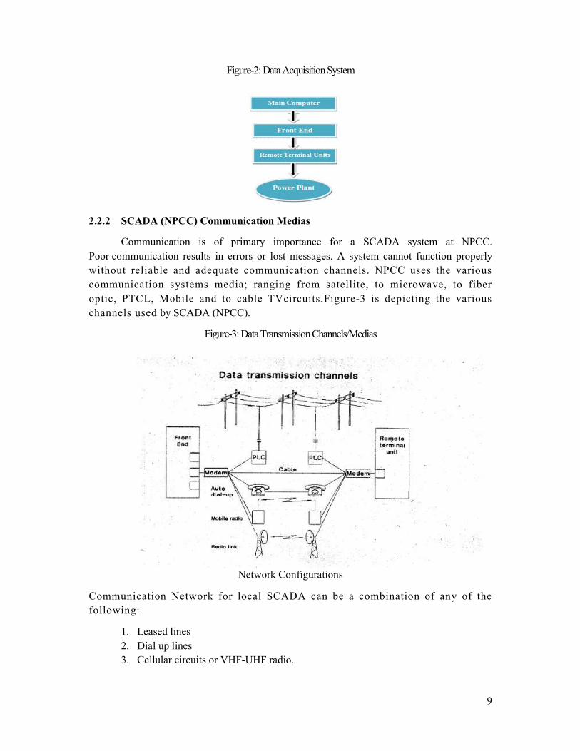
without reliable and adequate communication channels. NPCC uses the various
communication systems media; ranging from satellite, to microwave, to fiber
optic, PTCL, Mobile and to cable TVcircuits.Figure-3 is depicting the various
channels used by SCADA (NPCC).
Figure-3: Data Transmission Channels/Medias
Network Configurations
Communication Network for local SCADA can be a combination of any of the
following:
1. Leased lines
2. Dial up lines
3. Cellular circuits or VHF-UHF radio.
10
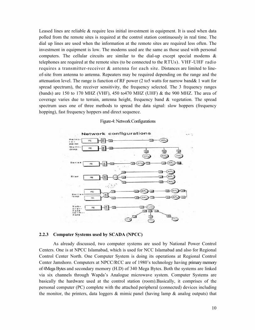
Leased lines are reliable & require less initial investment in equipment. It is used when data
polled from the remote sites is required at the control station continuously in real time. The
dial up lines are used when the information at the remote sites are required less often. The
investment in equipment is low. The modems used are the same as those used with personal
computers. The cellular circuits are similar to the dial-up except special modems &
telephones are required at the remote sites (to be connected to the RTUs). VHF-UHF radio
requires a transmitter-receiver & antenna for each site. Distances are limited to line-
of-site from antenna to antenna. Repeaters may be required depending on the range and the
attenuation level. The range is function of RF power (2 to5 watts for narrow band& 1 watt for
spread spectrum), the receiver sensitivity, the frequency selected. The 3 frequency ranges
(bands) are 150 to 170 MHZ (VHF), 450 to470 MHZ (UHF) & the 900 MHZ. The area of
coverage varies due to terrain, antenna height, frequency band & vegetation. The spread
spectrum uses one of three methods to spread the data signal: slow hoppers (frequency
hopping), fast frequency hoppers and direct sequence.
Figure-4: Network Configurations
2.2.3 Computer Systems used by SCADA (NPCC)
As already discussed, two computer systems are used by National Power Control
Centers. One is at NPCC Islamabad, which is used for NCC Islamabad and also for Regional
Control Center North. One Computer System is doing its operations at Regional Control
Center Jamshoro. Computers at NPCC/RCC are of 1980’s technology having primary memory
of 4Mega Bytes and secondary memory (H.D) of 340 Mega Bytes. Both the systems are linked
via six channels through Wapda’s Analogue microwave system. Computer Systems are
basically the hardware used at the control station (room).Basically, it comprises of the
personal computer (PC) complete with the attached peripheral (connected) devices including
the monitor, the printers, data loggers & mimic panel (having lamp & analog outputs) that
11
allows the operator to monitor & control the field data & distributed devices/equipment over
the plant or city. The PC serial port is connected to a suitable modem (system box) for
communication with the field RTUs. The PC will have the appropriate operating system (the
platform which the SCADA software is going to run under), the microprocessor, the hard
disk, the floppy disk drive, the CD-ROM drive, the memory (RAM), the graphical adapter,
support for multi-screen adapter boards and logical input/output for pen recorders, mimic
panel, etc.
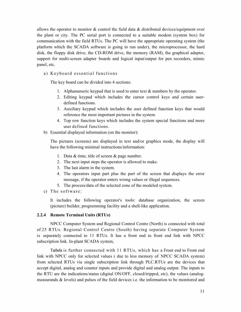
a ) Ke yb o a rd e s sen t i a l f u nc t i o n s
The key board can be divided into 4 sections:
1. Alphanumeric keypad that is used to enter text & numbers by the operator.
2. Editing keypad which includes the cursor control keys and certain user-
defined functions.
3. Auxiliary keypad which includes the user defined function keys that would
reference the most important pictures in the system.
4. Top row function keys which includes the system special functions and more
user defined functions.
b) Essential displayed information (on the monitor):
The pictures (screens) are displayed in text and/or graphics mode, the display will
have the following minimal instructions/information:
1. Data & time, title of screen & page number.
2. The next input steps the operator is allowed to make.
3. The last alarm in the system.
4. The operators input part plus the part of the screen that displays the error
message, if the operator enters wrong values or illegal sequences.
5. The process/data of the selected zone of the modeled system.
c) T he s o f t wa re :
It includes the following operator's tools: database organization, the screen
(picture) builder, programming facility and a shell-like application.
2.2.4 Remote Terminal Units (RTUs)
NPCC Computer System and Regional Control Centre (North) is connected with total
of 25 RTUs. Regional Control Centre (South) having separate Computer System
is separately connected to 11 RTUs. It has a front end to front end link with NPCC
subscription link. In-plant SCADA system,
Tarbela is further connected with 11 RTUs, which has a Front end to Front end
link with NPCC only for selected values ( due to less memory of NPCC SCADA system)
from selected RTUs via single subscription link through PLC.RTUs are the devices that
accept digital, analog and counter inputs and provide digital and analog output. The inputs to
the RTU are the indications/status (digital ON/OFF, closed/tripped, etc), the values (analog-
measurands & levels) and pulses of the field devices i.e. the information to be monitored and

12
reported to the master computer. To affect control on the remote devices, the analog
& discrete output of the RTU is connected to the pertinent devices/equipment. Discrete
output is used to drive an external relay, to operate a circuit breaker (closing it or tripping it),
dropping a section of the feeder by opening a pole mounted switch or a a pad-mounted
switchgear switch, to disconnect a service, to switch off a motor and other similar
applications. Analog output are used to remotely control devices that requires an increment
adjustment or a variable set point for example opening/closing a valve, controlling a tap
changer, etc. Some of the RTUs used in SCADA, are intelligent. They are
programmed to make certain decisions instead of sending the information to the master
computer and wait for the instruction to come back. Such devices could be considered as
upgraded to the controller level. The RTU requires a power supply, has several interfaces &
multiple ports with the protocol selectable on a per-port basis. Some of the RTUs also have a
microprocessor, RAM, real time clock, watchdog timer, LED indicators, internal diagnostics
routines, fiber optic interface and an internal (built-in) modem. Major elements of RTU used
by SCADA in Pakistan are shown in Figure-5.
Figure-5: RTU Major Elements
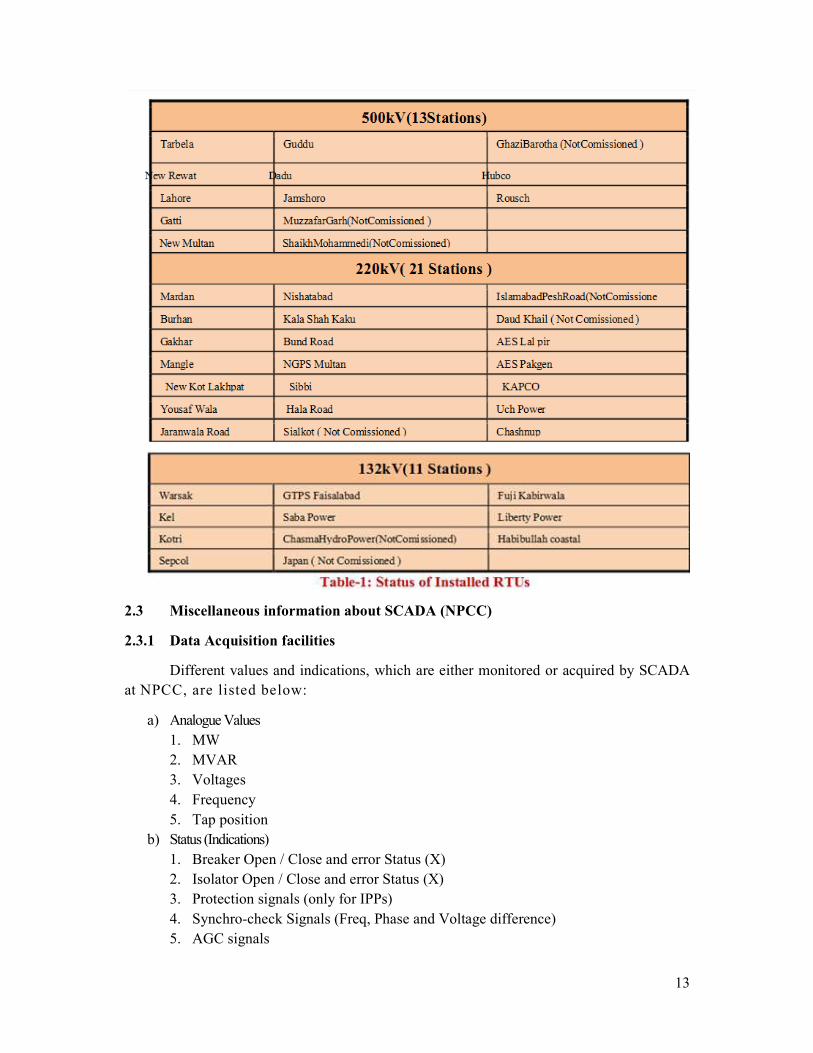
Complete status of installed RTUs used by SCADA in Pakistan is given in the Table-1.
500kV (13Stations), 220KV (21 Stations), 132 KV (11 Stations)
13
2.3 Miscellaneous information about SCADA (NPCC)
2.3.1 Data Acquisition facilities
Different values and indications, which are either monitored or acquired by SCADA
at NPCC, are listed below:
a) Analogue Values
1. MW
2. MVAR
3. Voltages
4. Frequency
5. Tap position
b) Status (Indications)
1. Breaker Open / Close and error Status (X)
2. Isolator Open / Close and error Status (X)
3. Protection signals (only for IPPs)
4. Synchro-check Signals (Freq, Phase and Voltage difference)
5. AGC signals
14
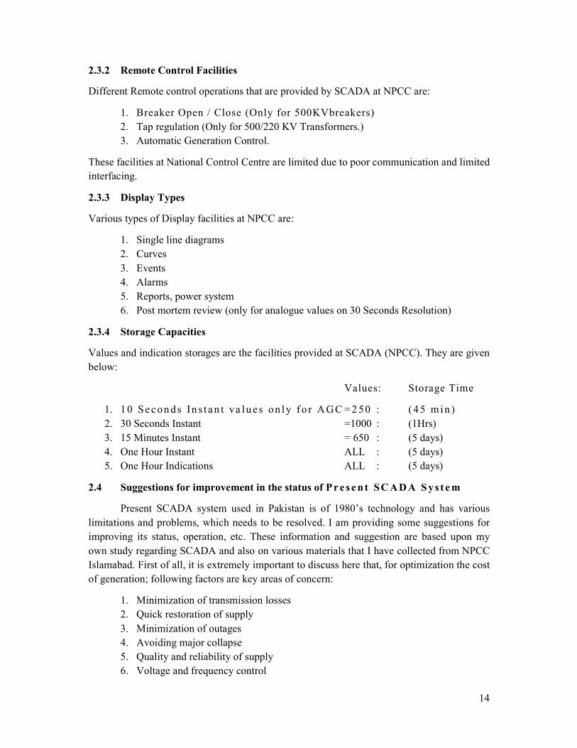
2.3.2 Remote Control Facilities
Different Remote control operations that are provided by SCADA at NPCC are:
1. Breaker Open / Close (Only for 500KVbreakers)
2. Tap regulation (Only for 500/220 KV Transformers.)
3. Automatic Generation Control.
These facilities at National Control Centre are limited due to poor communication and limited
interfacing.
2.3.3 Display Types
Various types of Display facilities at NPCC are:
1. Single line diagrams
2. Curves
3. Events
4. Alarms
5. Reports, power system
6. Post mortem review (only for analogue values on 30 Seconds Resolution)
2.3.4 Storage Capacities
Values and indication storages are the facilities provided at SCADA (NPCC). They are given
below:
Values: Storage Time
1. 1 0 Se c on ds In s t a n t va lu es on l y f o r A GC = 2 50 : ( 4 5 m i n )
2. 30 Seconds Instant =1000 : (1Hrs)
3. 15 Minutes Instant = 650 : (5 days)
4. One Hour Instant ALL : (5 days)
5. One Hour Indications ALL : (5 days)
2.4 Suggestions for improvement in the status of Pre sen t SCADA Sys tem
Present SCADA system used in Pakistan is of 1980’s technology and has various
limitations and problems, which needs to be resolved. I am providing some suggestions for
improving its status, operation, etc. These information and suggestion are based upon my
own study regarding SCADA and also on various materials that I have collected from NPCC
Islamabad. First of all, it is extremely important to discuss here that, for optimization the cost
of generation; following factors are key areas of concern:
1. Minimization of transmission losses
2. Quick restoration of supply
3. Minimization of outages
4. Avoiding major collapse
5. Quality and reliability of supply
6. Voltage and frequency control
15
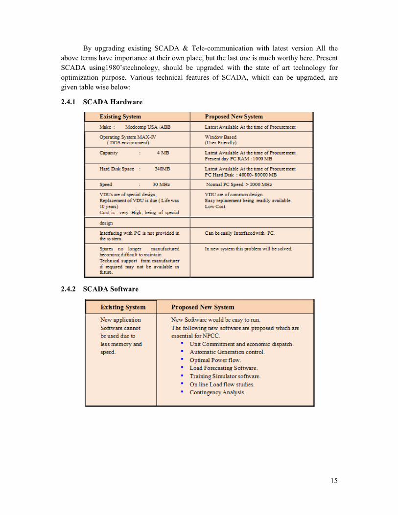
By upgrading existing SCADA & Tele-communication with latest version All the
above terms have importance at their own place, but the last one is much worthy here. Present
SCADA using1980’stechnology, should be upgraded with the state of art technology for
optimization purpose. Various technical features of SCADA, which can be upgraded, are
given table wise below:
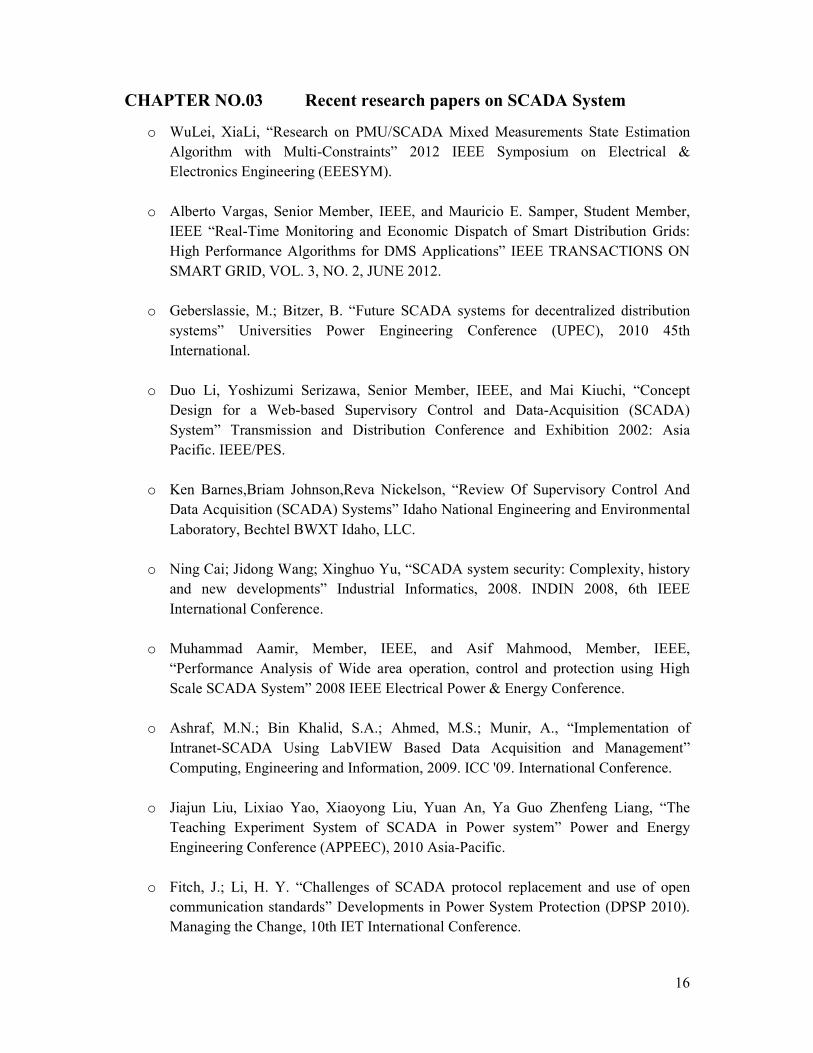
2.4.1 SCADA Hardware
2.4.2 SCADA Software
16
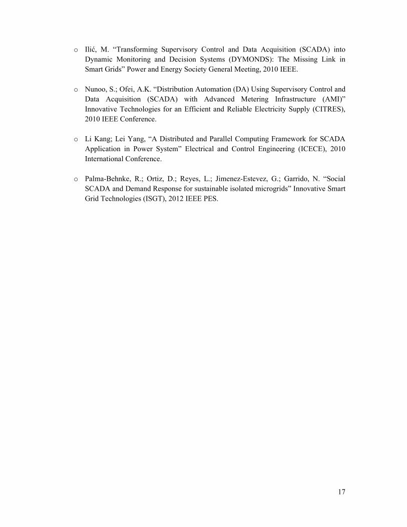
CHAPTER NO.03 Recent research papers on SCADA System
o WuLei, XiaLi, “Research on PMU/SCADA Mixed Measurements State Estimation
Algorithm with Multi-Constraints” 2012 IEEE Symposium on Electrical &
Electronics Engineering (EEESYM).
o Alberto Vargas, Senior Member, IEEE, and Mauricio E. Samper, Student Member,
IEEE “Real-Time Monitoring and Economic Dispatch of Smart Distribution Grids:
High Performance Algorithms for DMS Applications” IEEE TRANSACTIONS ON
SMART GRID, VOL. 3, NO. 2, JUNE 2012.
o Geberslassie, M.; Bitzer, B. “Future SCADA systems for decentralized distribution
systems” Universities Power Engineering Conference (UPEC), 2010 45th
International.
o Duo Li, Yoshizumi Serizawa, Senior Member, IEEE, and Mai Kiuchi, “Concept
Design for a Web-based Supervisory Control and Data-Acquisition (SCADA)
System” Transmission and Distribution Conference and Exhibition 2002: Asia
Pacific. IEEE/PES.
o Ken Barnes,Briam Johnson,Reva Nickelson, “Review Of Supervisory Control And
Data Acquisition (SCADA) Systems” Idaho National Engineering and Environmental
Laboratory, Bechtel BWXT Idaho, LLC.
o Ning Cai; Jidong Wang; Xinghuo Yu, “SCADA system security: Complexity, history
and new developments” Industrial Informatics, 2008. INDIN 2008, 6th IEEE
International Conference.
o Muhammad Aamir, Member, IEEE, and Asif Mahmood, Member, IEEE,
“Performance Analysis of Wide area operation, control and protection using High
Scale SCADA System” 2008 IEEE Electrical Power & Energy Conference.
o Ashraf, M.N.; Bin Khalid, S.A.; Ahmed, M.S.; Munir, A., “Implementation of
Intranet-SCADA Using LabVIEW Based Data Acquisition and Management”
Computing, Engineering and Information, 2009. ICC '09. International Conference.
o Jiajun Liu, Lixiao Yao, Xiaoyong Liu, Yuan An, Ya Guo Zhenfeng Liang, “The
Teaching Experiment System of SCADA in Power system” Power and Energy
Engineering Conference (APPEEC), 2010 Asia-Pacific.
o Fitch, J.; Li, H. Y. “Challenges of SCADA protocol replacement and use of open
communication standards” Developments in Power System Protection (DPSP 2010).
Managing the Change, 10th IET International Conference.
17
o Ilić, M. “Transforming Supervisory Control and Data Acquisition (SCADA) into
Dynamic Monitoring and Decision Systems (DYMONDS): The Missing Link in
Smart Grids” Power and Energy Society General Meeting, 2010 IEEE.
o Nunoo, S.; Ofei, A.K. “Distribution Automation (DA) Using Supervisory Control and
Data Acquisition (SCADA) with Advanced Metering Infrastructure (AMI)”
Innovative Technologies for an Efficient and Reliable Electricity Supply (CITRES),
2010 IEEE Conference.
o Li Kang; Lei Yang, “A Distributed and Parallel Computing Framework for SCADA
Application in Power System” Electrical and Control Engineering (ICECE), 2010
International Conference.
o Palma-Behnke, R.; Ortiz, D.; Reyes, L.; Jimenez-Estevez, G.; Garrido, N. “Social
SCADA and Demand Response for sustainable isolated microgrids” Innovative Smart
Grid Technologies (ISGT), 2012 IEEE PES.
18
CHAPTER 04 SCADA Systems in Future
As above we saw the fundamentals of SCADA and how it has emerged. In this
chapter we will examine some of the challenges and applications that need to be met in order
for SCADA to remain relevant to the new needs.
4.0 Interoperability
When SCADA was developed a few decades back, it was a relatively simple system
and the various components were all developed and put together by the manufacturer of the
hardware or the vendor who supplied it to clients. However the variety and complexity of
requirements in the recent times have given rise to the need for specialist developers.
Companies often buy the different components according to their requirements and put them
together, in a mix and match manner.
Therefore the specialist developers have to ensure interoperability of the component they take
care of. In other words, the components have to be developed in such a way that they can be
used with a variety of applications developed by different vendors.
The challenge here is that most SCADA systems are very application specific and each
component is tailor made to its specific application. Therefore, the components have to also
work across a number of application-specific platforms.
4.1 The Promise of Wireless Sensor Networking
The static, inflexible and centralized architecture of the system further limits the
interoperability of a SCADA system with other systems as well as their coverage of data.
Wireless Sensor Networking is an emerging area that can tackle this problem. With this
technology, sensors can be deployed with more ease and flexibility. For example, in a
SCADA system developed for gas/oil fields, sensors are typically placed at production wells
and injection walls. With wireless sensor networking technology, sensors can be placed at
other crucial places like pipelines and tanks at relatively lower costs. This greatly enhances
the efficiency of the SCADA system by making more information available.
The current SCADA systems are not enabled to be integrated with wireless
networking systems and new systems and software with this capability may have to be
developed to exploit this possibility.
4.2 Extensibility
Another area where the current SCADA systems are found lacking is extensibility. In
other words they are not equipped to be connected to new applications like safety alarm
systems, real-time communication networks based on new technology etc. This in turn limits
the ability of the RTUs to take proactive measures to prevent accidents.
19
4.3 What needs to be done?
We may broadly divide the requirements into three categories.
1. First of all, the communication architecture has to move on from being rigidly
centralized- they have to develop a flexible structure that allow communication
between different RTUs and other systems like embedded sensor networks and
mobile users on field. This can be achieved by adopting internet technologies for
networking, rather than the hitherto followed proprietary or link-level
connections. The use of IP empowers the physical network with software and
logical networks.
2. Further, open and interoperable protocols for communication and data
management have to be developed. The protocols have to address the issue of
what types of data is sent and to whom. For instance, raw data can be sent only to
the data server for archival. The supervisors, engineers or managers have to be
sent only status summaries and so on.
3. Finally, the RTUs and other components have to be designed in such a way that
unauthorized accessing and altering is not possible. In other words, data security
has to be maintained. Use of IP and open protocols especially can cause more
vulnerability security threats. The need for specialized industrial firewalls and
VPN solutions is thus another high priority area.