review of maxillary molar distalising appliances …...review of maxillary molar distalising...
TRANSCRIPT

FORUM ORTHODONTIC ORTODONTYCZNE FORUM296
Forum Ortod 2018; 14: 296-308
Review of maxillary molar distalising appliances with palatal anchorage on mini-implants
1, 2, 3, 4 Prywatna praktykaPrivate practice
1 Lek. dent. / DDS2 DDS, PhD, specialist in orthtodontics3 DDS, PhD, specialist in orthtodontics4 DDS, specialist in orthtodontics
Correspondence address:
trzonowych, miniimplanty ortodontyczne, szkieletowe
1996– 2018.
Maxillary molar distalisation is one of treatment methods for patients with Angle class II. Intraoral appliances supported
Mini-implants are additionally used to reduce this side effect. The area of the hard palate is the best anatomical place to
complications. To present issues associated with appliances used for maxillary molar distalisation that are based on bone anchorage in the hard palate region. Material
database and the Polish Medical Bibliography with the
implants, skeletal anchorage. 37 positions from the years 1996–2018 were selected and analysed. As a result
A B C Analiza statystyczna D E Redagowanie pracy F
A Study design B C Statistical Analysis D E Manuscript Preparation F Literature Search
Katarzyna Becker2 3
4 FE
DBA E F
DBA E F
DBA E F

FORUM ORTHODONTIC ORTODONTYCZNE FORUM297
Review of maxillary molar distalising appliances with palatal anchorage on mini-implants
MCPP.
miniimplanty ortodontyczne, zakotwienie szkieletowe
twarzy (2).
Wskazaniem do leczenia ortodontycznego z zastosowaniem
by palatal mini-implants do not lead to loss of anchorage in the anterior segment. At the stage of anterior teeth retraction they can be used for stabilisation of the distalised segment.
those placed on the external side of the dental arch. They
typical of the prototypes they originate from, i.e. rotation
of teeth is made possible by appliances whose force acts at the height of the CR (centre of resistance) of teeth being
molar distalisation, orthodontic mini-implants, skeletal anchorage
IntroductionMalocclusions are the result of skeletal disorders,
factors, with simultaneous interdependencies in the sagittal,
It may cause dysfunctions and affect facial aesthetics (2). The choice of a method of orthodontic treatment for
patients with Angle class II depends on the facial type,
a patient. The indications for orthodontic treatment with the use of maxillary molar distalisation techniques include
of growth, as well as when class II occlusal relations are a consequence of mesial displacement of lateral teeth in the maxilla and accompany secondary crowdings. In
of premolars. Mesocephalic or brachycephalic facial types are the most suitable for this method of treatment. With
therefore in such cases typical distalisation is not recommended (3).
The headgear extraoral appliance used since the beginning

FORUM ORTHODONTIC ORTODONTYCZNE FORUM298
M. Sanecka et al.
Pierwszym aparatem wykorzystywanym m.in. w celu
trzonowych (3, 8, 9, 10, 11).
of maxillary molars, and as a consequence, posterior rotation
leads to loss of anchorage (7). One way to further strengthen
Only the introduction of skeletal anchorage in the form of
loss of anchorage in the anterior section of the dentition. Miniscrews (Miniscrew Implants, MSI) may be part of appliances used for molar distalisation (3, 8, 9, 10, 11).
Nazwa Name
Opis aparatu Description of the appliance
Rysunek schematyczny
Schematic diagram
BAPA-Bone Anchored Pendulum Appliance
(Kircelli 2006)
1 MSI lub 2 MSI w przedniej okolicy podniebienia, bocznie od szwu podniebiennegoPłytka Nance’a połączona z MSI za pomocą żywicy akrylowej utwardzanej na zimno w jamie ustnej pacientaSprężyny TMA zamocowane w pierścieniach zębów trzono-wych wywierają siłę dystalizującą
Cechy charakterystyczne Utrudniona higiena pod płytką Nance’a- ryzyko stanu zapal-nego wokół miniimplanu Brak możliwości przekształcenia w aparat retencyjny (9,21,26).
1 MSI or 2 MSIs in the anterior palatal region, laterally from the midpalatal sutureNance button bonded to MSI with cold cure acrylic resin in the patient's oral cavityTMA springs embedded in molar bands apply a distalising force
Typical features Problems with hygiene under the Nance button – risk of inflam-mation around a mini-implant It is not possible to transform it into a retention appliance (9,21,26).
Ryc. 1.Fig. 1.
FORUM ORTHODONTIC ORTODONTYCZNE FORUM299
Review of maxillary molar distalising appliances with palatal anchorage on mini-implants
Nazwa Name
Opis aparatu Description of the appliance
Rysunek schematyczny
Schematic diagram
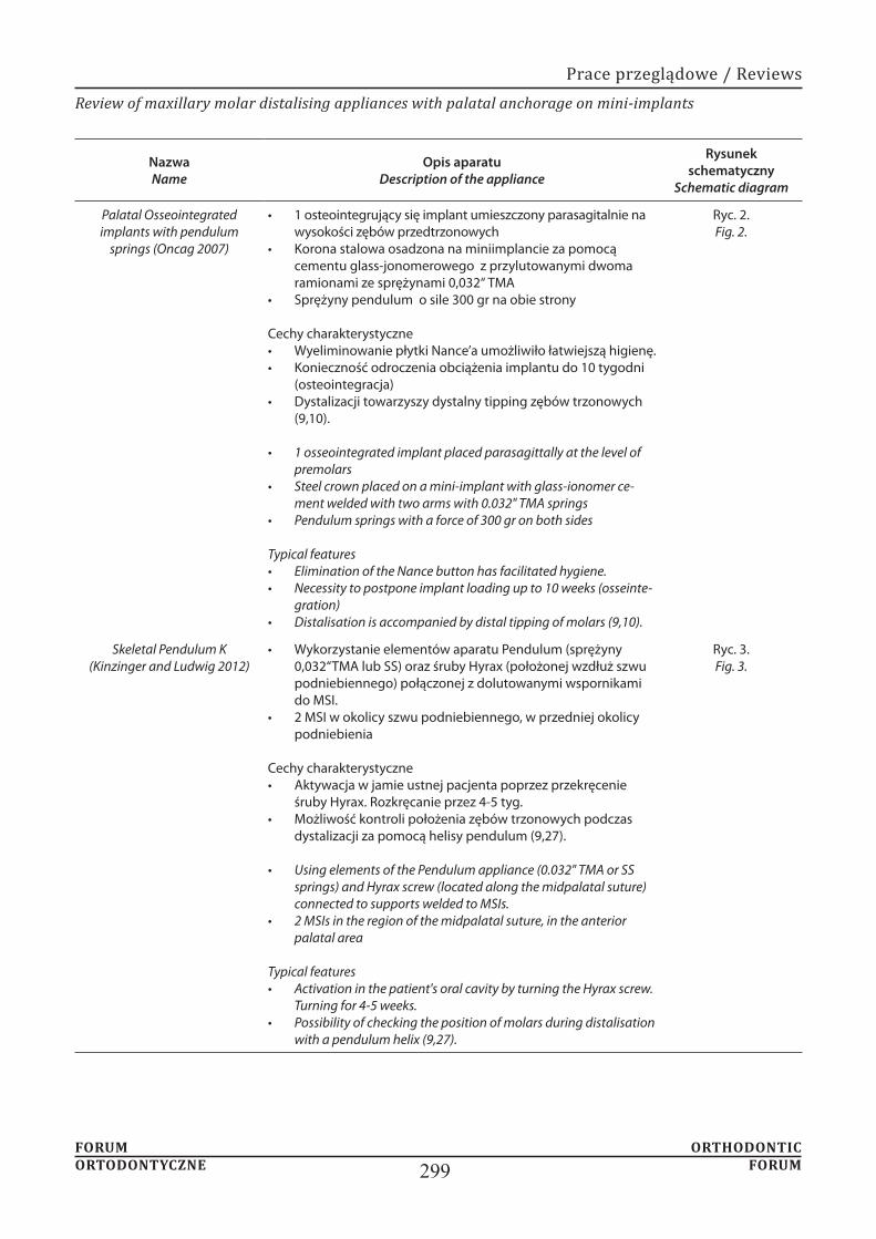
Palatal Osseointegrated implants with pendulum
springs (Oncag 2007)
1 osteointegrujący się implant umieszczony parasagitalnie na wysokości zębów przedtrzonowychKorona stalowa osadzona na miniimplancie za pomocą cementu glass-jonomerowego z przylutowanymi dwoma ramionami ze sprężynami 0,032“ TMASprężyny pendulum o sile 300 gr na obie strony
Cechy charakterystyczne Wyeliminowanie płytki Nance’a umożliwiło łatwiejszą higienę.Konieczność odroczenia obciążenia implantu do 10 tygodni (osteointegracja)Dystalizacji towarzyszy dystalny tipping zębów trzonowych (9,10).
1 osseointegrated implant placed parasagittally at the level of premolarsSteel crown placed on a mini-implant with glass-ionomer ce-ment welded with two arms with 0.032" TMA springsPendulum springs with a force of 300 gr on both sides
Typical features Elimination of the Nance button has facilitated hygiene.Necessity to postpone implant loading up to 10 weeks (osseinte-gration)Distalisation is accompanied by distal tipping of molars (9,10).
Ryc. 2.Fig. 2.
Skeletal Pendulum K (Kinzinger and Ludwig 2012)
Wykorzystanie elementów aparatu Pendulum (sprężyny 0,032“TMA lub SS) oraz śruby Hyrax (położonej wzdłuż szwu podniebiennego) połączonej z dolutowanymi wspornikami do MSI.2 MSI w okolicy szwu podniebiennego, w przedniej okolicy podniebienia
Cechy charakterystyczne Aktywacja w jamie ustnej pacjenta poprzez przekręcenie śruby Hyrax. Rozkręcanie przez 4-5 tyg.Możliwość kontroli położenia zębów trzonowych podczas dystalizacji za pomocą helisy pendulum (9,27).
Using elements of the Pendulum appliance (0.032" TMA or SS springs) and Hyrax screw (located along the midpalatal suture) connected to supports welded to MSIs.2 MSIs in the region of the midpalatal suture, in the anterior palatal area
Typical features Activation in the patient's oral cavity by turning the Hyrax screw. Turning for 4-5 weeks.Possibility of checking the position of molars during distalisation with a pendulum helix (9,27).
Ryc. 3.Fig. 3.

FORUM ORTHODONTIC ORTODONTYCZNE FORUM300
M. Sanecka et al.
Nazwa Name
Opis aparatu Description of the appliance
Rysunek schematyczny
Schematic diagram
Skeletonized Distal Jet
(Kinzinger 2006)
2 MSI umieszczone w przedniej okolicy podniebienia, parasagitalnie połączone łukiem SS z zębami przedtrzonowymi (kompozytem typu flow)Sprężyny teleskopowe na łuku biegnącym do pierścieni na zębach trzonowych dostarczając siłę 200gr na stronęŁatwość przekształcenia w łuk utrzymujący efekt dystalizacjiMożliwość kontroli rotacji poprzez aktywację zagięć bagnetowych (9,28,29,30).
2 MSIs placed in the anterior part of the palate, parasagittally connected via an SS arch with premolars (flow composite)Telescopic springs on the arch running to the molar bands apply a force of 200 grams per sideEasy transformation into an arch to maintain the effects of distalisationPossibility to control rotation by activating bayonet bends (9,28,29,30).
Ryc. 4.Fig. 4.
TopJet (Winsauer 2011)
Zastosowano 2 MSI bocznie od szwu pośrodkowegoAparat prefabrykowany: posiada: podwójne prowadnice: jedna aktywna- dystalizująca ( power module) z otwar-tą sprężyną NiTi , druga do regulacji (adjustment module) umieszczone osiowo w podwójnej teleskopowej rurce , łuk TPA(dostępny w 7 rozmiarach)element w kształcie litery C do połączenia z MSI (C- clip)Dostępne 2 zakresy sił: TopJet 250 (siła 250 gr) oraz TopJet 360 (Siła 360 gr)
Cechy charakterystyczne Możliwość dystalizacji jednostronnej (wtedy zastosowanie 1 MSI)Uniknięcie etapów laboratoryjnych i umieszczenie aparatu na jednej wizycieMaksymalna dystalizacja zębów trzonowych wynosi 14 mm (9,31).
2 MSIs applied laterally from the midpalatal suturePrefabricated appliance: with the following elements: double guides: one active – distalising (power module) with an open NiTi spring, the other for adjustment (adjustment module) placed axially in a double telescopic tube, TPA arc (available in 7 sizes)C-shaped element to be connected to MSI (C-clip)2 force ranges available: TopJet 250 (force of 250 gr) and TopJet 360 (force of 360 gr)
Typical features Possibility of one-side distalisation (1 MSI is used then)Avoiding laboratory stages and appliance placement on one visitMaximum molar distalisation is 14 mm (9,31).
Ryc. 5.Fig. 5.

FORUM ORTHODONTIC ORTODONTYCZNE FORUM301
Review of maxillary molar distalising appliances with palatal anchorage on mini-implants
Nazwa Name
Opis aparatu Description of the appliance
Rysunek schematyczny
Schematic diagram
Horseshoe jet (Bowman 2006)
2 MSI umieszczone podniebiennie w okolicy przedtrzonowców, dowiązane ligaturą metalową do łukuŁuk w kształcie podkowy połączony 2 dodatkowymi elementami z pierścienia-mi na pierwszych zębach trzonowych Sprężyny NiTi działają z siłą 240 gr na stronę, aktywacja następuje poprzez napięcie sprężyn od strony mezjalnejAktywacja 3-4 razy przez okres leczenia ok. 6-7 miesięcy do osiągnięcia nadko-rekty klasy I na zębach trzonowych
Cechy charakterystyczne Łatwość przekształcania w aparat retencyjnyMożliwości jednoczesnej retrakcji zębów przednichMożliwość reimplantacji bez konieczności zmiany aparatu (9,27,28).
2 MSIs placed palatally near premolars, tied with a metal ligature to the archHorseshoe arch connected with 2 additional elements to first molar bands NiTi springs act with a force of 240 gr per side, activation takes place through spring tension from the mesial sideActivation 3–4 times during the treatment period approx. 6–7 months to achieve overcorrection of Class I on molars
Typical features Easy to convert into a retention appliance Possibility of simultaneous retraction of anterior teethPossibility of reimplantation without the need to change the appliance (9,27,28).
Ryc. 6.Fig. 6.
MISDS Mini-screw Implant
Supported Distalization System (Pa-
padoupoulos 2008)
Część oporowa: 2 MSI umieszczone w przedniej okolicy podniebienia między kłami a pierwszymi zębami przedtrzonowymi parasagitalnieCzęść aktywna: łuk stalowy podkowiasty 0,040”z 2 pętlami w miejscu MSI prze-chodzi przez położone wysoko rurki do wyciągu zewnątrzustnego dolutowane do pierścieni na zębach trzonowych od strony podniebiennej, otwarte spręży-ny NiTi oraz śruby stopujące.Sprężyny NiTi dostarczają siły ok. 200 gr na stronę
Cechy charakterystyczne Siła dystalizująca na poziomie CR zębów bocznych powodując czysty ruch równoległy eliminując dystalne nachylenie zębów trzonowychSamoistne przesunięcie zębów przedtrzonowych i kłów do tyłuŁatwe przekształcenie w aparat retencyjny umożliwiający retrakcję zębów przednich (2,9,12,16,32).
Resistance part: 2 MSIs placed in the anterior part of the palate between the cani-nes and first premolars parasagittallyActive part: 0.040" horseshoe steel arch with 2 loops in place of MSI passes through highly located tubes to the extraoral traction, welded to molar bands from the palatal side, open NiTi springs and stopping screws.NiTi springs apply a force of approx. 200 grams per side
Typical features Distalising force at the level of CR of lateral teeth causing a clean parallel motion eliminating distal inclination of molars Spontaneous movement of premolars and canines backwardsEasy conversion into a retention appliance allowing for retraction of anterior teeth (2,9,12,16,32).
Ryc. 7.Fig. 7.

FORUM ORTHODONTIC ORTODONTYCZNE FORUM302
M. Sanecka et al.
Nazwa Name
Opis aparatu Description of the appliance
Rysunek schematyczny
Schematic diagram
Beneslider (Wilmes and
Drescher 2008)
2 MSI (Benefit) umieszczone w przedniej okolicy podniebienia parasagitalnie Prefabrykowany system Beneslider: płytka Beneplate, rurka wsuwane do szlufki pierścienia na trzonowcu- Benetube sliding hook, stopery- Benetube locks, łuk stalowy w kszatłcie podkowySprężyny działają z siłą 240 g na stronę
Cechy charakterystyczne Równoległy ruch dystalny trzonowcówDuże i zmienne tarcie powoduje relatywnie długi czas leczenia około 8-10 mie-sięcy aby uzyskać przesunięcie 4-5 mmBrak etapu laboratoryjnego Umieszczenie apartu na jednej wizycie (9,33,34,35,36).
2 MSIs (Benefit) placed in the anterior part of the palate, parasagittally Prefabricated Beneslider system: Beneplate, tube inserted into the band loop on a molar – Benetube sliding hook, stoppers – Benetube locks, steel horseshoe arch The springs apply a force of 240 g per sideTypical features Parallel distal movement of molarsLarge and variable friction causes relatively long treatment time of about 8–10 months to obtain a shift of 4–5 mmNo laboratory stage Appliance placement on one visit (9,33,34,35,36).
Ryc. 8.Fig. 8.
Dual force distalizer
(Oberti 2009)
2 MSI umieszczone wzdłuż szwu podniebiennegoPłyta akrylowa z dwoma otworami,przez które wprowadza sie miniimplanty oraz czterema łukami z drutu 0,028 SS na wysokości koron zębów (2 policzko-we, 2 podniebienne),Ramiona umieszczone w rurce o średnicy 0,045 cala przylutowanej po stronie policzkowej i podniebiennej pierśnieni zębów trzonowych4 sprężyny NiTi o sile 250-300 g, 4 stopery mezjalne służące do aktywacji oraz 4 stopery dystalne w celu ograniczenia przesuwania zębów
Cechy charakterystyczne Po dystalizacji usuwane są łuki policzkowe, a pozostała aparatu służy zakotwie-niu podczas retrakcji.Siła działa poniżej CR dystalizowanych zębów, co powoduje ich dystoinklinację (9,37).
2 MSIs placed along the palatal sutureAcrylic plate with two holes through which mini-implants are inserted, and four 0.028 SS wire arches at the height of teeth crowns (2 buccal, 2 palatal),Arms are placed in a 0.045 inch diameter tube welded on the buccal and palatal side of molar bands4 NiTi springs with a force of 250–300 g, 4 mesial stoppers for activation and 4 distal stoppers to limit tooth movement
Typical features After distalisation, buccal archwires are removed and the rest of the appliance is used for anchorage during retraction.The force acts below the CR of the teeth undergoing distalisation, resulting in their distal inclination (9,37).
Ryc. 9.Fig. 9.

FORUM ORTHODONTIC ORTODONTYCZNE FORUM303
Review of maxillary molar distalising appliances with palatal anchorage on mini-implants
Rycina 10. MCPP
Cel AimThe aim of this paper is to present issues associated with appliances used for maxillary molar distalisation that are based on bone anchorage in the hard palate region, on the
FORUM ORTHODONTIC ORTODONTYCZNE FORUM304
M. Sanecka et al.
miniimplanty ortodontyczne, szkieletowe zakotwienie.
Prace oparte na badaniach na ludziach, publikowane
Oryginalne badania prospektywne i retrospektywne
Nance (aparat pendulum) (2, 4, 7, 12, 13).W celu zminimalizowania lub niedopuszczenia do utraty
czasu leczenia ortodontycznego (2).
database and the Polish Medical Bibliography with the
implants, skeletal anchorage. Papers published until 2018 were selected. 37 papers presenting the issues corresponding
analysed.
Papers based on human studies, published in Polish and English.Articles presenting a detailed description of the construction of appliances used for distalisation.
descriptions of case studies.
nine distalising appliances modelled on three basic
a typical drawback, namely the loss of anchorage, which is manifested as mesial migration of premolars, incisal protrusion, increase in the anterior-posterior space, distal inclination, extrusion and distal rotation of molars. These
plates (pendulum appliance) are used in addition to the
the anterior region of the dental arch, bone anchorage elements are used, and they are connected to a molar distalising appliance in different ways (3, 8, 9, 10, 11).
by an orthodontist. Shortening of time of orthodontic
bone layer, thickness and quality of the mucous membrane
screw. A thicker layer of the keratinised compact bone, attached mucosa, as well as a safe distance (min. 0.5 mm)
of treatment (14, 15).Mini-implants used for distalisation can be placed both

FORUM ORTHODONTIC ORTODONTYCZNE FORUM305
Review of maxillary molar distalising appliances with palatal anchorage on mini-implants
Keles Slider.
Bone Anchored Pendulum Appliance – BAPA (Kircelli 2006), Palatal Osseointegrated Implants with Pendulum Springs (Oncag 2007) oraz Skeletal Pendulum K (Kinzinger i Ludwig 2012) przedstawia tabela nr 1.
areas” such as the hard palate, the maxillary tuberosity, or
with a thicker layer of the cortical bone and the presence of attached mucosa. The risk of loss for mini-implants placed in this area is lowest (17). In this area, there is also no risk of contact with the roots of teeth undergoing
greater, compared to the use of mini-implants on the
a distance of 5 mm from the midpalatal suture is optimal for the placement of mini-implants, and there is no risk
20).Current miniscrew-supported distalising appliances are
modelled mainly on intraoral distalising appliances such
the Nance button on one side and to the tubes on the palatal
a distalisation force of 230 grams per side of the dental
Pendulum appliance, i.e. Bone Anchored Pendulum Appliance – BAPA (Kircelli 2006), Palatal Osseointegrated Implants with Pendulum Springs (Oncag 2007) and Skeletal Pendulum K (Kinzinger and Ludwig 2012).
appliance (American Orthodontics, Sheboygan, Wis) that has been used by clinicians widely, and has many
steel springs embedded into the 0.036" telescopic tubes, connected by means of a bayonet bent steel arch with palatal tubes of first molars bands. Telescopic tubes run at the height of the centre of resistance of the molars.
Compression of a spring applies an orthodontic force that
In 2001, Keles designed the appliance, which was named Keles Slider after him. It consists of a larger Nance button (with an anterior bite plane) located in the anterior part

FORUM ORTHODONTIC ORTODONTYCZNE FORUM306
M. Sanecka et al.
tubes on first molar bands. These tubes are placed parallel to the occlusion plane and welded at 5 mm to the top to
Nance button there are stopping screws and NiTi springs applying a force of 200 grams. At the tip of the archwire,
that splits the occlusion is not only to support anchorage
the dentition (22, 23). Table 3 presents MSI-supported
(Bowman 2006), Miniscrew Implant Supported
In order to eliminate anchorage loss, construction of
has been combined with mini-implants in different ways.
(indirect anchorage) or by completely anchoring the appliance on miniscrews (direct anchorage) (9). In the case of direct anchorage, spontaneous displacement of premolars
This type of anchoring can also be used for en-masse distalisation of the upper dental arch.
Modified C – palatal plate MCPP that has been introduced by Park is the appliance of a completely different design, although also based on bone anchorage on the palate, and it uses direct anchorage on mini-implants (18). The use of an appliance is recommended for distalisation of upper
construction and method of applying a distalising force
supported by palatal mini-implants. The MCPP consists of a smaller metal plate with three holes located in the midpalatal suture area between the second premolar and
and two arms, which are directed towards the dental arch.
a chosen direction of a force and to increase the range of action of elastic elements or springs (18). By using the
for distalisation of the whole arch is 300 g/side. Elastic elements (closed springs) are placed between selected notches on the arch of the MCPP appliance and hooks placed on the palatal arch, and are welded to the palatal surface of first molar bands (18, 25).

FORUM ORTHODONTIC ORTODONTYCZNE FORUM307
Review of maxillary molar distalising appliances with palatal anchorage on mini-implants
1.
2.
3. bez utraty zakotwienia segmentu przedniego.
4.
5.
Summary
distalisation based on bone anchorage (mini-screws)
1. Mini-implants, which are placed palatally, enable to
they are not free of the side effects typical of the prototypes they originate from, i.e. rotation and
teeth is made possible by appliances whose force acts at the height of the CR (centre of resistance) of
2.
as preparation for subsequent therapy.3.
the loss of anchorage of the anterior segment. Palatal
4. It is possible to transform a distalising appliance
been distalised at the stage of retraction of anterior teeth.
5. Appliances with mini-screws used as direct anchorage allow for distal drift of premolars.
1.
476-84.
2. ortodontycznym. Elamed 2014.
3.
4.
5.
6. mandibular dentition after maxillary molar distalization using
7.
8.
9. of orthodontic miniscrew implants for the treatment of Class II

FORUM ORTHODONTIC ORTODONTYCZNE FORUM308
M. Sanecka et al.
10. osteointegrated implant combined with pendulum springs for
277- 84.
11.
12. Papadopoulos MA. Orthodontic treatment for the Class II non-
2006.
13.
14.
15. thickness in adults with cone beam computerised tomography.
16.
17.
18. Comparison of treatment effects of total arch distalization using
19. measurements and cone-beam computed tomography-based
20. and cortical bone thickness for mini-implant placement in adults.
21. consequent to maxillary molar distalization with the bone-
22.
23. 23. Keles A. Maxillary unilateral molar distalization with sliding
501-15.
24. of palatal plate for nonextracion treatment in an adolescent boy
859-69.
25.
26.
27.
28.
anchorage for noncompliance maxillary molar distalization. Am
29.
672-8.
30.
31.
32. Papadopoulos M. Orthodontic treatment of Class II malocclusion
33.
34.
494-501.
35.
36.
37. distalization with the dual-force distalizer supported by mini-