review of acceptable flash rusting for ship coatings...introduction . currently, several shipyards...
TRANSCRIPT

Review of Acceptable Flash Rusting for Ship Coatings
Final Report
Prepared for: Advanced Technology Institute
Submitted by: Atlantic Marine Florida, LLC Elzly Technology Corporation
Project Participants: The Advisory Council
SSPC International
November, 2007

Executive Summary Steel surface preservation is critical to Navy ship maintenance. A key part of the process is surface preparation. Currently, several shipyards utilize ultra high pressure waterjetting (UHPWJ) to prepare steel for painting. This report investigates a key concern with UHPWJ: the impact of “flash rusting” on coating life. Flash rusting can occur under certain environmental conditions when the steel is left sufficiently wet following UHPWJ. Flash rust’s impact on coating life is debated. Reducing or eliminating flash rusting can increase the cost of surface preparation. The U.S. Navy standard item 009-32 only allows painting over “Light” flash rust as defined by SSPC SP-12 WJ2L. Light flash rust can be obtained by properly operated closed-loop UHPWJ systems. However, areas with complex shapes do not accommodate the closed-loop equipment. Hand lance UHPWJ equipment is commonly used to clean these areas. Because hand lances do not incorporate water removal devices, surfaces tend to remain wet longer and can develop flash rust beyond the “Light” condition (i.e., Moderate or Heavy flash rust). In such cases secondary surface preparation is required to return the flash rust to a “Light” condition. This added process can increase the cost of UHPWJ surface preparation of an entire underwater hull by 20%. To better understand the impact of flash rusting on coating life, this project compared the performance of coatings applied to four (4) Navy hulls prepared with closed-loop UHPWJ systems on broad areas and hand lance UHPWJ with minimal secondary surface preparation in complex hull areas. Personnel present during the preservation work and during these inspections agreed that the complex areas exhibited areas of Moderate flash rusting (the contractor would not have been allowed to paint over Heavy flash rust). Coating performance in the two areas was compared. The data suggest that there was no difference in the two areas on four ships after exposure lives of five to six years. This lends support to the argument that there is no need for secondary surface preparation after preparing the surfaces with hand lance equipment, at least as performed by this shipyard. It also encourages additional inspections on ship hulls and / or tanks with well documented surface conditions before painting for confirmation. The report also investigated the ability of industry personnel to discern different levels of flash rust in accordance with the SSPC SP-12 standards. The analysis of common panels suggested that industry personnel could clearly establish a break point between the Moderate and Heavy grades of flash rusting as defined by the three-tier SSPC SP-12 standard. Personnel were less able to agree on distinctions between Light and Moderate. This issue would be of less importance if the Navy / industry agreed that coatings performed similarly acceptable over both Light and Moderate flash rust.
2

Table of Contents
Executive Summary .............................................................................................................................2 Table of Contents .................................................................................................................................3 Introduction ..........................................................................................................................................4
Conclusions ..................................................................................................................................5 Recommendations ................................................................................................................................6 Background ..........................................................................................................................................7
Coating Performance over Flash Rusted Surfaces ...........................................................................7 Industry Standards for Quantifying Flash Rust..............................................................................11
Field Condition Evaluation ................................................................................................................12 Visual Inspections ..........................................................................................................................13
USS Klakring (FFG-42) .............................................................................................................13 USS Hue City (CG-66) ..............................................................................................................13
Physical Inspections .......................................................................................................................14 USS Boone (FFG-28).................................................................................................................14 USS Samuel B. Roberts (FFG-58) .............................................................................................16
Round Robin Evaluation of Flash Rust Standards .............................................................................21 Procedures ......................................................................................................................................21 Results ............................................................................................................................................22
Appendix A – Guidelines for Evaluating Flash Rust .........................................................................24 Appendix B – Data Sheets from Physical Testing .............................................................................27 Appendix C – Detailed Round Robin Results....................................................................................61
3

Introduction Currently, several shipyards utilize ultra high pressure waterjetting (UHPWJ) to prepare steel for painting. One drawback of UHPWJ is the occurrence of “flash rust” on the surface after cleaning. Because coatings have historically been applied over clean “white metal” it is somewhat of a paradigm shift for the industry to begin painting over flash rust. There are two key questions surrounding the issue of painting over flash rust:
• What levels of flash rust can be painted over? • How do we quantify the level of flash rust?
Some commercial owners allow coatings to be applied over “Moderate” levels of flash rust. The U.S. Navy only allows painting over “Light” levels of flash rust due to their lower level of risk tolerance and longer expected service life. Closed-loop UHPWJ systems routinely provide surfaces which are better than the Light flash rust standard. However, areas on ships which have complex shapes do not accommodate the closed loop equipment. Hand lance equipment is commonly used to clean these areas. Because hand lances do not incorporate water removal devices, surfaces tend to remain wet longer and develop Moderate or Heavy levels of flash rust. Costly secondary surface preparation processes are required to reduce the flash rust to the “Light” condition. It has been estimated that this added process increases the cost of surface preparation up to 20% on an underwater hull. The report documents the results of a project is to improve the process of UHPWJ surface preparation in shipyards by reducing the impact of flash rust concerns. Specific project objectives are to:
• Investigate and document the performance of coatings over WJ2-M (Moderate levels of flash rust) to create a body of data on field performance
• Investigate the reliability of flash rusting standards and develop guidance and
recommendations for the industry on their use
4

Conclusions
1. None of the visual or physical inspections revealed differences in performance after five or six years which could be attributed to the different waterjetting surface preparation processes (closed-loop UHP vs hand-lance). This suggests that secondary surface preparation is probably unnecessary after hand-lance waterjetting with the procedures used by the shipyard. Elimination of the secondary surface preparation may reduce the cost of surface preparation for an underwater hull by 20%.
2. Industry experience and recollection of personnel from the original painting project suggests
that these surfaces would have “Light” and “Moderate” flash rust, respectively. We could not confirm the initial condition of the areas based on testing of the aged, coated surface. Ideally, future comparisons could be made where the level of flash rust was photographically documented.
3. There are ambiguities which exist between the written descriptions used for “Light” and
“Moderate” flash rust in the SSPC SP-12 standard. The differences between the descriptors for “Moderate” and “Heavy” flash rust are less ambiguous.
4. The round robin test results suggested that industry personnel could clearly establish a break
point between the Moderate and Heavy grades of flash rusting as defined by the three-tier SSPC SP-12 standard. Personnel were less able to agree on distinctions between Light and Moderate. This issue would be of less importance if the Navy / industry agreed that coatings performed similarly acceptable over both Light and Moderate flash rust.
• The showed between 50% and 88% (average 74%) agreement between participants
on the level of flash rust for panels rated “Light” or “Moderate.” • The round robin test results showed 94% agreement on the condition of a single
panel rated “Heavy.” 5. The laboratory data are inconsistent in predicting the effect of painting over flash rusting in
the absence of detectable surface salts. The most significant concern appears to be a combination of cathodic protection and painting over heavy flash rust which leads to increased cutback. Such cutback would exceed normal Navy paint qualification standards. There does not appear to be increased cutback when painting over Light or Moderate flash rusting as compared to controls and the Navy paint qualification standards of MIL-PRF-23236 or MIL-PRF-24647.
5

Recommendations
1. Continue to build the database of performance data for coating applied over “Moderate” flash rusted surfaces where they can be documented on Navy ships. This data will complement commercial data and laboratory test data. If flash rust levels higher than “Light” can be shown to be provide acceptable performance, the US Navy can recognize substantial cost savings.
2. Conduct mechanistic studies into the interaction of various flash rust levels with the epoxy
primers used by the US Navy. Improved understanding of the mechanisms which dominate the interaction between the flash rust and the coating (e.g., adhesion) would improve our ability to interpret the performance observations.
3. Clarify some of the wording in the SSPC WJ-12 standard as it pertains to Light and
Moderate levels. The test data shows that the standard is certainly acceptable for differentiating among the three levels of flash rust, but there is room for improvement.
4. Develop an instrument which electronically provides objective evidence of the level of flash
rust. Such an instrument would improve the speed and efficiency of the inspection process.
6

Background Cleaning steel with high pressure water was introduced in the United States in the 1970’s. However, it was not until the early 1990’s that ultrahigh pressure waterjet cleaning (UHPWJ) became a generally accepted practice to prepare steel for coatings. Much research and work was done to develop UHPWJ for surface preparation.1 This section discusses some of the work in the literature regarding coating performance over flash rusted surfaces and industry standards for quantifying flash rust.
Coating Performance over Flash Rusted Surfaces In conjunction with the development of standards to assess flash rusting, researchers have investigated the performance of coatings over flash rusting under laboratory test conditions. A report for the US Navy2 documents a study of several tank and underwater hull coating systems applied over various degrees of flash rusting followed by subsequent exposure to a marine environment or seawater immersion. The study included four levels of flash rusting – less than light (LTL), light (LFR), medium (MFR), and heavy (HFR). Panels were exposed in various immersion tests for eight months. Figure 1 plots the percent failed at the end of testing assuming an ASTM D 610 failure criteria of “8” (corresponding to 0.1% of the surface with corrosion) and a rating of “7” (0.3% surface corrosion). First, observe that the percentage of the test panels which failed varies depending on how failure is defined (i.e., as “7” or “8”). Consider the data associated with a failure criterion of “8” in Figure 1. The data show that flash rust per se, tends to increase rust-through vs. a clean surface. Increased levels of flash rusting correlate with incremental coating failure over conditions ranging from clean steel to medium flash rust. In follow-on testing3, this same behavior was not observed over a period of nine months. In this study, three levels of flash rusting were created, including “light,” “medium,” and “heavy.” Control tests consisting of a SSPC SP-10 abrasive blasted substrate were included. In this study all flash rusting surfaces were created via a similar water jetting and variable time-of-wetness process. The averages of replicate panels all exhibited between a 9.5 and 10 ASTM D 610 rating. In the previous tests, residual salt levels prior to painting were not confirmed; in the subsequent tests (with less breakdown) they were confirmed to be below the chloride detection limits.
1 L. Frenzel, What Effect Does Waterjet Cleaning Have on the Surface and Surface Preparation?, 2007 American WJTA Conference and Expo, August 19-21, 2007, Houston, Texas. 2 Effect Of Flash Rusting Over Waterjetted Surfaces On Coating Performance, Report to NAVSEA, 2000. 3 Berry, Fred, et al., “Flash Rusting: Characterization and Effect of Coating Performance,” Presented at SSPC.
7

Rusting over Flash Rusting
0%10%20%30%40%50%60%70%
7 8
ASTM D 610 Criterion
% o
f Pop
ulat
ion
Faile
dSP-10LTLLFRMFR
Figure 1 - Percent of Population Failing for Different ASTM D 610 Criterion
Figure 2 shows a plot of the magnitude of cutback from an intentional scribe following 9 months of seawater exposure. The data do not show a gross effect of surface condition on the extent of cutback – all of the observed levels are low within the context of other, similar controlled tests. This data implies that flash rust may not decrease coating performance if the flash rust is free of invisible contaminants (e.g., salts).
Cutback in Seawater Immersion
00.5
11.5
22.5
33.5
44.5
5
MIL-P-24441 NovaPlate EuroNavy
Cut
back
(mm
)
SP-10LFRMFRHFR
Figure 2 - Cutback on Flash-Rusted Panel (Freely Corroding)
The Navy strives to employ some form of cathodic protection on all immersed surfaces. Thus, cathodic disbondment may be of more concern in an immersion environment as compared to the underfilm cutback for freely corroding steel. Figure 3 shows a compilation of cathodic disbondment data for immersion coatings applied over clean steel and flash rusted steel in three studies. The first two studies were previously described. The third study4 included panels that were water-jetted in a simulated seawater ballast tank; all of the panels were considered to be either SP-10 or medium/heavy flash rust (the data are plotted as heavy flash rust). In studies one and three,
4 UHP Waterjetting, Coating Application And Performance Testing Inside Mock-Up Shipboard Tanks, Report to NAVSEA, October 2005.
8

heavy flash rusting seemed to cause significantly more coating disbondment vs. the SP-10 control surface. Study two showed negligible effect of flash rust on cathodic disbondment.
Cathodic Disbondment over Flash Rusting
0
10
20
30
40
50
SP-10 LFR MFR HFR
Degree of Rusting
Dis
bond
men
t (m
m)
Study 1Study 2 Study 3
Figure 3 - Cathodic Disbondment over Flash Rusting
0
5
10
15
20
25
30
35
40
45
50
0% 10% 20% 30% 40% 50% 60% 70% 80% 90% 100%
Cum. Probability
Dis
bond
men
t (m
m)
SP-7/SP-10LFRMFRHFR
24647 Rqt.
23236 Rqt.
Figure 4 - Distribution of Cathodic Disbondment Cutback Data from Various Sources
Figure 4 is a probability distribution function for cathodic disbondment data from various studies in the literature. The plot shows that cathodic disbondment over “heavy” rusting is more significant than over SP-10, light, or medium conditions. This finding suggests that painting over heavy levels of flash rusting may be a concern. To place the finding into perspective, the two lines on the plot are requirements from MIL-PRF-23236 (4% of total panel surface area) and MIL-PRF-24647 (0.5 inch or 12.7 mm of cutback).5 Note that the mathematical mode (probability of 0.5) of the heavy
5 The MIL-PRF-23236 requirement is converted to a corresponding disbondment length by assuming a six-inch by twelve-inch test panel with uniform disbondment from a circular intentional holiday.
9

data is higher than the requirements for MIL-PRF-23236 and MIL-PRF-24647. The data for Light and Moderate flash rust has a similar trend to the data for the abrasive blasted surfaces. The performance in this test does not necessarily correlate to a given service life, but it does suggest that coatings could meet the specification requirements when applied over Light and Moderate levels of flash rust. The similarity of the data suggests a similar level of risk for performance over these two levels of flash rust and abrasive blasting. Another study investigated the performance of four coating systems exposed to 1,440 hours salt fog testing.6 The four, 2-coat coating systems studied were epoxy vinyl/silicone alkyd, epoxy/ polyurethane, solvent-based acrylic (2cts), and water-borne epoxy/water-borne acrylic. Each of the systems was nominally 240 µm thick. Subsequent to the salt fog testing, scribe cutback and pull off adhesion tests were performed to characterize the coating performance. The authors concluded that surfaces with flash rusting after UHPWJ did not perform as well in the salt fog tests as those prepare by abrasive blasting. Furthermore, a reduction in performance was observed as flash rusting increased. The authors noted that the initial level of the surface before UHP waterjetting largely determines coating performance – that is a surface which was heavily rusted prior to UHPWJ cleaning did not perform as well as a surface which was clean prior to UHPWJ cleaning. However, it is worth noting that their “flash rusting” occurred during outdoor exposure from “April 2001 to June 2001.” Assuming this means the panels were exposure for several weeks, the “flash rust” may not be representative of that which would occur over a shorter duration (i.e., hours). Allen7 describes comparison testing of ballast tank coatings applied over hydroblasted, abrasive blasted and mechanically cleaned surfaces. In describing the results, Allen says “No wholesale detachment occurred on any of the schemes after almost two years of cyclic testing. However, some of the mechanically prepared schemes showed blistering and rust rashing after two years of testing and also poor adhesion when scratched with a penknife.” Furthermore, adhesion data reported in the paper does not show any failure at the flash rusted substrate. In 2000, Morris published the follow-up to Allen’s one-year test results.8 The paper presented the results of three years of cyclic testing. He concludes “In all cases, regardless of the generic coating system used, paint adhesion was found to be far superior on steel prepared by UHP waterjetting and dry abrasive blasting than on surfaces prepared with a hand wire brush or needlegun. There was no significant difference in performance between substrates prepared by abrasive blasting and UHP waterjetting (regardless of whether flash rusting occurred).” Generally, the literature contains conflicting data on the performance of coatings over flash rusted surfaces. The data which exists is fairly limited and does not address several key issues:
• What are the specific characteristics of “flash rust” used in various test programs? • Why is “flash rust” different from other rust? • Fundamentally, why would flash rust not interfere with coating performance? • What are the critical characteristics of this “benign” level of flash rust?
6 Philippe Le Calve, DCN, Lorient, France; Phillipe Meunier, SNCF, Paris, France; Jean Marc Lacam, DGA, Paris France, “Evaluation of the Behavior of Reference Paint Systems after UHP Waterjetting”, JPCL, January 2003. 7 Bill Allen, “Evaluating UHP Waterjetting for Ballast Tank Coating Systems,” PCE, October 1997 8 Malcolm Morris, “Update: Evaluating UHP Waterjetting as Preparation for Ballast Tank Coatings,” PCE Sept, 2000, p 54
10

Industry Standards for Quantifying Flash Rust The history of flash rust characterization has included various standards.9, , , , , ,10 11 12 13 14 15 Most of the standards for flash rusting rely on qualitative or at best semi-quantitative determinations of the level of flash rusting. Visual (photographic comparators) and physical (wiping and tape tests) criteria are employed to differentiate among levels of flash rusting. Current industry standards predominately use written descriptions of visual observations and relatively simple physical tests to determine whether flash rust is acceptable for coating application. Different interpretations arise because the visual standards represent discrete levels of flash rusting while the field conditions will likely be some intermediate level. At least four initiatives are presently underway to develop more quantitative test procedures to reduce disputes.16, , ,17 18 19 These techniques include electrochemical measurements, colorimetric measurements, digital image analysis, and measurement of the corrosion product weight. As a group, these quantitative test techniques require analysis of a specific “spot” rather than the entire surface and they will be more complicated than the present procedures. Furthermore, they are several years from becoming industry standards. However, if such quantitative tests can be developed they will have several benefits to the industry. Quality tests which provide quantitative evidence in an electronic format have been shown to be more cost-effective for the industry.
9 ISO 8501-4, Preparation of steel substrates before application of paints and related products -- Visual assessment of surface cleanliness -- Part 4: Initial surface conditions, preparation grades and flash rust grades in connection with high-pressure water jetting 10 SSPC-SP 12/NACE 5: Surface Preparation and Cleaning of Steel and Other Hard Materials by High- and Ultrahigh-Pressure Water Jetting Prior to Recoating 11 SSPC-VIS 4/NACE VIS 7: Guide and Reference Photographs for Steel Surfaces Prepared by Waterjetting 12 International Paints Hydroblasting Standards (http://www.international-pc.com/pc/technical/tech_papers/hydrophot.asp) 13 Degrees of Flash Rusting - Guidelines for Visual Assessment of Flash Rusting. Jotun Marine Coatings, Sandefjord, 1996 14 STG (Schiffbautechnische Gessellschaft) Guide No. 2222, Definition of Preparation Grades for High-Pressure Waterjetting, 1995 15 Photo Reference of Steel Surfaces Cleaned by Water Jetting., Hempel Marine 16 M. Islam, W. McGaulley, J. Tagert, J. Ellor, and M. Evans, “Experimentation to Develop a Quantitative Method for Characterizing the Level of Flash Rusting Formed on Carbon Steel after Ultra High Pressure Waterjetting,” presented at PACE 2006, January, 2006. 17 “Digital Image Processing for Rust Assessment,” presentation by Muehlhan Equipment Services at the NSRP Ship Production Panel Meeting, Tampa FL, January 2006. 18 C.S. Tricou, “Quantifying the Impact of Flash Rust on Coating Performance,” Final Report submitted to Naval Sea Systems Command under contract #N00039-97-D-0042/0377, January 2005. 19 Philippe Le Calve, DCN, Lorient, France; Phillipe Meunier, SNCF, Paris, France; Jean Marc Lacam, DGA, Paris France, “Quantification of the Products of Corrosion after UHP Waterjetting”, JPCL, November 2002.
11

Field Condition Evaluation As part of this project, we identified a series of ships including Oliver Hazard Perry class frigates and Ticonderoga class Aegis guided missile cruisers which had hull preservation work performed in the 2001-2002 timeframe. The work was performed at a shipyard in the southeast United States. During this preservation work, the contractor requested approval to deviate from “H-B 2½ L to H-B 2½ M”20 on the hand lance hydroblasted areas. Approval of these requests was granted with the following constraints:
• The hand lance cleaned areas were kept to the minimum feasible • The amount of time between hand-lance blasting and blow-down with dry air was
minimized • The amount of time between blow-down with dry air and application of the primer coat was
minimized • Evidence of coating manufacturer concurrence was provided
Coincident with the present project, three frigates and one cruiser which were preserved with the above described deviation were to be dry-docked. During each of the dockings, we collected as much evidence as possible to determine if there were any differences in the performance of the coating over the close-loop cleaned areas versus the hand lance cleaned areas. The inspection team consisted of:
• Consulting engineer form Elzly Technology who performed the testing • A SERMC representative who was also the SBS performing the G-point inspections when
the surface preparation and coating was originally accomplished • Shipyard personnel who were present when the surface preparation and coating was
originally accomplished For the first two ships, we performed a visual observation of the hull. If significant performance differences existed where the hand lance cleaned surfaces were allowed to be painted over, coating blistering and/or adhesion loss may be more prevalent in the hand lance cleaned areas versus the broad areas cleaned with the closed-loop UHPWJ equipment. As this section shows, there were no visually detectable performance differences. Based on the results of the visual inspections, a strategy was developed to collect physical data on the coating performance in the hand-lance versus closed-loop cleaned areas. On the next two ships, physical data which included adhesion tests and complete removal of the coating were performed. Significant differences in the pull-off adhesion or observation of a corroded surface under the coating would be evidence of decreased coating performance in the hand lance cleaned areas. No such differences were observed. This section of the report provides additional details on the hull inspections. The results suggest that no measurable performance difference between the hand-lance prepared surfaces and the closed-loop UHPWJ cleaned surfaces.
20 An H-B 2½ M is nominally equivalent to WJ-2M. Similarly, an H-B 2½ L is nominally equivalent to WJ-2L.
12

Visual Inspections Visual inspections were performed by the project team for the first two ships. Visual inspections were made from the drydock floor after the ship was hauled and cleaned with low pressure water. Areas which could not be cleaned with the closed-loop system were inspected for signs of coating failure such as peeling paint, rusting, blistering, and undercutting at defects. The inspections were documented with written comments and photographs.
USS Klakring (FFG-42) The USS Klakring (FFG-42) had underwater hull coating removed and reapplied in November, 2002. A deviation request was made to allow an H-B 2½M condition on the jet lance hydro-blasted areas in lieu of the required H-B 2½L. The deviation request was accompanied by a letter from International Paint indicating that the primer, Intertuf 262 was suitable for use over an H-B 2½M prepared surface. An Inspection Deficiency Report approving the deviation was issued on October 29, 2002 provided that the jet lanced area of the underwater hull did not exceed 10%. On January 30, 2007 the USS Klakring was inspected in drydock. There were no visual differences evident between areas that were machine cleaned and hand-lance cleaned. The underwater hull was in good shape with negligible blistering. The paint appeared intact and well adhered. The freeboard coating was also in good condition with the exception of localized rusting at locations of mechanical damage and near overboard discharges.
USS Hue City (CG-66) The USS Hue City (CG-66) had underwater hull coating removed and reapplied in December, 2002. A deviation request was made to allow an H-B 2½M condition on the jet lance hydro-blasted areas in lieu of the required H-B 2½L. It was also requested that the area of allowable deviation be expanded to 40%. The deviation request was accompanied by a letter from International Paint indicating that the primer, Intertuf 262 was suitable for use over an H-B 2½M prepared surface. An Inspection Deficiency Report approving the deviation was issued on November 18, 2002 provided that the jet lanced area of the underwater hull was held to the minimum feasible, time between hand lance cleaning and blow down was minimized, and time between blow-down and fist coat was minimized. On February 20, 2007 the USS Hue City was inspected in drydock. There were no visual differences evident between areas that were machine cleaned and hand-lance cleaned. The underwater hull was in good shape with negligible blistering. The paint appeared intact and well adhered. The freeboard coating was also in good condition with the exception of localized rusting at locations of mechanical damage and near overboard discharges. The rudders had 100% failure of the antifouling to the EC2216 system. The top layer of ablative antifouling coating was lost as the marine growth dried. In-tact ablative antifouling coating remained on the hull.
13
Physical Inspections The visual inspections did not differentiate performance over the hand lance versus closed-loop machine cleaned areas. It was decided that a physical evaluation could potentially be more informative than the visual inspections. A test procedure was developed which included:
• Document the condition of the test area prior to testing (DFT, photographic, descriptive). • Selectively remove the topcoat (AF or Alkyd) to expose the anticorrosive coating. • Perform various tests on the anticorrosive to ascertain the integrity of the coating (pull-off
adhesion, coating capacitance, film thickness). • Remove a small area of the epoxy (nominally 3-inch by 3-inch), allowing a visual
examination of the steel substrate and an assessment of the primer/steel bond. • All areas where steel is exposed will have an epoxy coating brush applied for temporary
protection. • Test areas are repaired as required by the ship owner.
The physical test procedures were designed to better characterize the condition between the primer and the steel surface. This is the interface which one would expect to be affected if the flash rust associated with the hand lance cleaning impacted the coating performance. Specifically, the pull-off adhesion should fail at a location other than the primer/substrate (indicating that the weakest point in the system is cohesive). Where failure to the substrate is observed, values in excess of 800psi are indicative of good adhesion. Where the coating is chemically removed to expose the substrate, it is expected that the substrate will not contain any active corrosion. Appendix B contains detailed data sheets for the physical inspections. The following sections discuss the results of the physical inspections.
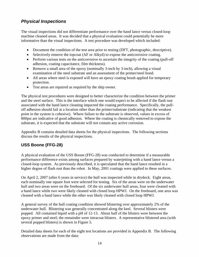
USS Boone (FFG-28) A physical evaluation of the USS Boone (FFG-28) was conducted to determine if a measurable performance difference exists among surfaces prepared by waterjetting with a hand lance versus a closed-loop system. As previously described, it is speculated that the hand lance resulted in a higher degree of flash rust than the robot. In May, 2001 coatings were applied to these surfaces. On April 2, 2007 (after 6 years in service) the hull was inspected while in drydock. Eight areas, each nominally one square foot were selected for testing. Six of the areas were on the underwater hull and two areas were on the freeboard. Of the six underwater hull areas, four were cleaned with a hand lance while two were likely cleaned with closed loop HPWJ. On the freeboard, one area was cleaned with a hand lance while the other was likely cleaned with closed loop HPWJ. A general survey of the hull coating condition showed blistering over approximately 2% of the underwater hull. Blistering was generally concentrated along the keel. Several blisters were popped. All contained liquid with a pH of 12-13. About half of the blisters were between the epoxy primer and steel; the remainder were intracoat blisters. A representative blistered area (with several popped blisters) is shown in Figure 5. Detailed data sheets for each of the eight test locations are provided in Appendix B. The following observations are made from the data:
14

• The anticorrosive coating consisted of two coats of epoxy – a red primer and grey
intermediate coat. In the underwater hull locations the anticorrosive was 10-15 mils thick with 2-15 mils of antifouling coating. In the freeboard area, the anticorrosive was 20-30 mils with an additional 30 mils of alkyd topcoat.
• Nearly all of the adhesion tests failed either within the primer or at the adhesive. One adhesion pull which was performed over a blister failed at the substrate under low load (240 psi). Adhesion values as high as 1700 psi were observed.
• Physical removal of the coating showed further evidence that the primer was well adhered in all locations. Red primer was difficult to remove from the profile depths. Unburnished peaks had a brownish coloration, but there was no evidence of “loose” corrosion.
• Only two areas showed indications of compromised adhesion. Figure 6 shows a close-up of one pull-off test was placed over a latent blister (test 1-7). This test failed to the substrate at 240 psi. Figure 7 shows two small areas comprising 2% of the coating removed from patch 8 (0.25 in²) was easily removed to the substrate with mechanical force. Remaining tests on both of these areas demonstrated excellent adhesion.
In summary, the physical inspection revealed no evidence of coating failure which would logically be traced to a systematic or process problem associated with hand lance cleaning. Of the surfaces inspected, all had tightly adherent epoxy primer. Blistering of the underwater hull coating was observed along the keel.
Figure 5. Representative blistering along the keel in the vicinity of the stern air masker.
15

Figure 6. Pull-off adhesion test 1-7, situated near blistering on keel.
Figure 7. Small areas of substrate revealed when excavating at test location 8.
USS Samuel B. Roberts (FFG-58) A physical evaluation of the hull coating on the USS Samuel B. Roberts (FFG-58) was performed to determine if a measurable performance difference exists among surfaces prepared by waterjetting with a hand lance versus closed loop UHPWJ. The closed loop UHPWJ system was reported to achieve a surface condition better than WJ-2L. The hand lance cleaned areas were reported to have a WJ-2M condition which was allowed to be coated by a local variance in 2002.
16

In August-October, 2002 coatings were applied over surfaces reported to have both moderate and light flash rust. The anti-corrosive system applied to FFG-58 included International Paint (IP) Intertuf KHA 303 red and IP Intertuf KHA 303 gray. The underwater hull AF system included IP Interspeed BRA 640 red, IP Interspeed BRA 642 black. On July 15-16, 2007 (after approximately 5 years of service) the hull was inspected while in drydock. Eight areas, nominally one square foot were selected for testing. All eight areas were on the underwater hull. Of the eight areas, four were cleaned with a hand lance while four were likely cleaned with a closed loop UHP robot. No significant coating anomalies were observed during a visual survey of the exterior hull. There was minor blistering at various locations (including along the keel and below overboard discharges). Areas which did not receive a complete antifouling coating due to the locations of docking blocks were also noted. Detailed inspections were conducted at eight locations, somewhat randomly selected by the project team. The locations were in matched pairs where one patch was several feet below the boot stripe and its companion patch was near an appendage which would have precluded cleaning with closed-loop HPWJ equipment. Data sheets for each of the eight test locations are provided in Appendix B. The following observations are made from the data:
• The anticorrosive coating consisted of two coats of epoxy – a red primer and grey intermediate coat. In the underwater hull locations the anticorrosive was 10-15 mils thick with 2-15 mils of antifouling coating.
• Adhesion tests failed at various locations through the coating system including within the primer and between the primer and substrate. Adhesion values between 1,119 and 2,453 psi were observed.
Subsequent to the physical testing, the coating was removed from a 10 by 10 inch area of patches 3 and 4. Coating removal was accomplished with repeated application of a paint stripper and scrubbing with a brass brush. Figure 8 and Figure 9 show the substrate of patch 3 and 4, respectively after coating removal.
17

Figure 8. Test Patch 3 with nominally 100 square inches of coating removed.
Figure 9. Test patch 4 with nominally 100 square inches of coating removed.
Physical removal of the coating showed further evidence that the primer was well adhered to a sound substrate. In both cases, the primer was difficult to clean from the depths of the profile. The exposed steel had a definite anchor profile which visually appeared to exceed 1 mil. Figure 10 shows a close-up of the steel surface at patch 4.
18

Figure 10. Close-up of the substrate revealed at patch 4.
The lower patch (patch 3) had a stripe of stain through the center. Adhesion test 3-1 was situated such that part of the dollie was on the stained area and part was on the clean area. While the adhesion test failed to the substrate on the stained area, the pull test failed at 1968 psi – far in excess of most manufacturers’ requirements for a new coating. Figure 11 shows a close-up of the stain in the area of adhesion test as well as the adhesion test after failure.
Figure 11. Close-up of adhesion test 3-1 and the test location after coating removal.
After further review of the stain, it was observed that the stain lined up with a streak of blisters that continued up to an overboard discharge. The type of discharge was not determined, but it is probable that the dark staining is associated with the discharge rather than an anomaly related to flash rust associated with hand-lance surface preparation. Figure 12 shows the relationship between the test patch, observed blistering, and the overboard discharge. In summary, the physical inspection revealed no evidence of coating failure which would logically be traced to a systematic or process problem associated with hand lance cleaning. Of the surfaces inspected, all had tightly adherent epoxy primer.
19

Figure 12. Location of test patch relative to overboard discharge. Note line of blistering highlighted
by arrows in the photo.
20

Round Robin Evaluation of Flash Rust Standards One of the concerns with painting over flash rust is that the standards are subject to interpretation. To quantify this concern, the project included a “round-robin” evaluation of the flash rust descriptions in SSPC SP-12, Surface Preparation and Cleaning of Steel and Other Hard Materials by High- and Ultrahigh-Pressure Water Jetting Prior to Recoating. The round robin test is discussed in the first part of this section. The second part of this section contains a review of the SSPC standard as well as other standards in light of the results of the round robin.
Procedures The round robin evaluation was intended to quantify the variability in the interpretation of the wording in SSPC SP-12 and VIS-4, the dominate US Industry Standards for rating flash rust. To perform the round-robin test, eight steel test panels were prepared with ultrahigh pressure waterjetting and allowed to flash rust. Table 1 shows the detailed processing of each panel.
Table 1. Round Robin Test Panel Preparation Initial Condition Flash Rust
Development Remediation
1 Sheltered storage for approx 24 hours
1000 psi wash, 24 hours sheltered storage
2 Sheltered storage for approx 24 hours
1000 psi wash, 24 hours sheltered storage
3 Sheltered storage for approx 48 hours
None
4 Sheltered storage for approx 48 hours
None
5 Unsheltered storage for approx 72 hours
None
6 Unsheltered storage for approx 48 hours
1000 psi wash, 24 hours sheltered storage, solvent wipe
7
New steel, 2 mil profile, 1 mil PCP, abrasive blasted and allowed to rust in yard for a week prior to 40,000 psi hydroblast with a hand lance
Unsheltered storage for approx 24 hours
Solvent wipe
8 New steel, 2 mil profile, 1 mil PCP, weathered prior to 40,000 psi hydroblast with a hand lance
Unsheltered storage for approx 12 hours
None
All of the panels were prepared by Atlantic Marine personnel at their Jacksonville, FL facility. The panels were each nominally 2-foot square. All of the test panels originally contained preconstruction primer. The pre-construction primer was removed from seven of the panels with abrasive blasting. The panels were allowed to weather outdoors for approximately a week. The test panels were then high pressure waterjet cleaned using a hand lance and allowed to flash either outside or in a covered area. The level of flash rust was varied by adjusting the location of exposure, time of exposure and in some cases adding a remediation step (water wash or solvent wipe).
21

The test panels were available on-site at the Sea Turtle Inn in Atlantic Beach, FL for evaluation. Volunteers were solicited from the 2007 attendees at the Hull Preservation Subcommittee of the NAVSEA Standard Specification for Ship Repair and Alteration Committee (SSRAC). Eighteen of the attendees participated in the round-robin evaluation. Figure 13 shows the demographics of the participants. The participants equally represented the owner (Navy in this case) and contractor perspectives. Of the participants responding to the question, all had some level of NACE training.
Owner RepConsultantContractorNo Response
NACE Level 1NACE Level 2NACE Level 3NACE CIPNo Response
Figure 13. Round Robin Participant Demographics.
Results Appendix C contains photographs and detailed results for each of the test panels in the study. Figure 14 shows a summary of the percentage of people rating each panel “light,” “moderate,” or “heavy.” In Appendix C and in Figure 14, the panels are sorted in order from lightest to heaviest based on the average rating received.
0%
20%
40%
60%
80%
100%
8 6 3 4 7 1 2 5
Test Panel Number
Perc
enta
ge o
f Res
pond
ents
HeavyModerateLightNone
Figure 14. Distribution of Panel Ratings.
The data suggest strong consensus on the panel judged to have “heavy” flash rust. All but one of the participants determined that this panel had heavy flash rust (94% agreement). The panels rated “light” or “moderate” had between 88% and 75% consensus with the exception of panel 7. There was significant disagreement over whether panel 7 had moderate (50%) or light (39%) flash rust.
22
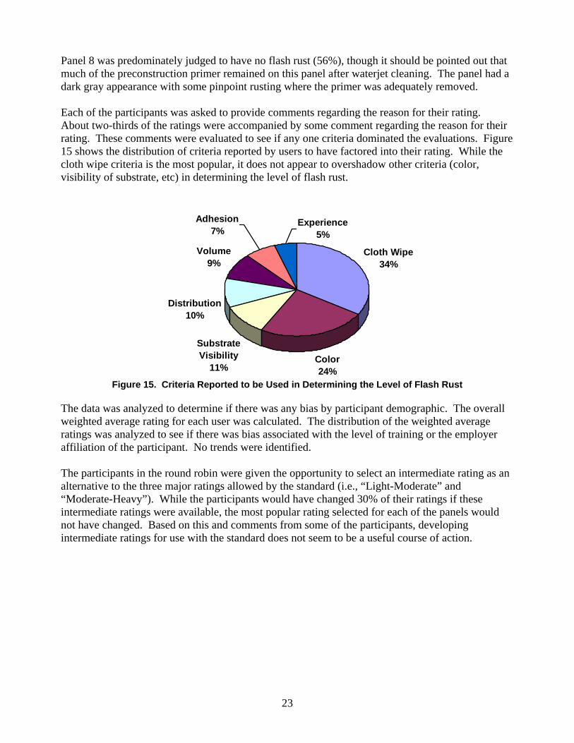
Panel 8 was predominately judged to have no flash rust (56%), though it should be pointed out that much of the preconstruction primer remained on this panel after waterjet cleaning. The panel had a dark gray appearance with some pinpoint rusting where the primer was adequately removed. Each of the participants was asked to provide comments regarding the reason for their rating. About two-thirds of the ratings were accompanied by some comment regarding the reason for their rating. These comments were evaluated to see if any one criteria dominated the evaluations. Figure 15 shows the distribution of criteria reported by users to have factored into their rating. While the cloth wipe criteria is the most popular, it does not appear to overshadow other criteria (color, visibility of substrate, etc) in determining the level of flash rust.
Cloth Wipe34%
Color24%
Substrate Visibility
11%
Distribution10%
Volume9%
Adhesion7%
Experience5%
Figure 15. Criteria Reported to be Used in Determining the Level of Flash Rust
The data was analyzed to determine if there was any bias by participant demographic. The overall weighted average rating for each user was calculated. The distribution of the weighted average ratings was analyzed to see if there was bias associated with the level of training or the employer affiliation of the participant. No trends were identified. The participants in the round robin were given the opportunity to select an intermediate rating as an alternative to the three major ratings allowed by the standard (i.e., “Light-Moderate” and “Moderate-Heavy”). While the participants would have changed 30% of their ratings if these intermediate ratings were available, the most popular rating selected for each of the panels would not have changed. Based on this and comments from some of the participants, developing intermediate ratings for use with the standard does not seem to be a useful course of action.
23

Appendix A – Guidelines for Evaluating Flash Rust When ultrahigh pressure waterjet cleaning is used for steel surface preparation, some degree of flash rust is inevitable. Flash rusting can be greatly minimized using closed-loop systems which incorporate vacuum removal of the water and debris. As a practical matter, areas will usually exist where the steel surface has a higher time-of-wetness due to running water or mist. When waterjetting is performed with an open-loop system (e.g., hand lance) some degree of flash rust will almost always occur. Flash rust is commonly characterized using subjective evaluation criteria. Some common criteria used to describe flash rust include:
Description of flash rust color • Light tan, tan-brown, yellow, yellow-brown, red-yellow, red-brown, etc. Description of flash rust dispersion on surface • “Patchy”, “uniform”, “present in patches”, “scattered,” etc. Description of flash rust adhesion • “Tightly adherent,” Loosely adherent,” etc. Ease of removal of flash rust • Material used for test – “object,” “hand,” “tape,” “cloth,” etc. • Amount of motion/pressure used – “brushed,” “lightly wiped,” “applied,” etc. • Amount of resulting marking – “light,” “significant,” etc. • Relative ease of marking – “easily,” “not easily,” etc. Description of degree to which the cleaned surface is visible beneath the flash rust (opacity of the layer) • “Obscures,” “obscures completely,” “completely hides original surface,” etc.
Time of development of flash rust
• Minutes, hours, days Table 2 shows descriptions of various levels of flash rusting from four different standards. Note the subtle but perhaps important differences among the descriptions. For example, in the moderate levels of flash rust the color is described as “red-brown,” “yellow/brown,” “clearly perceptible change in colour,” or “light tan-brown.” Similarly, there are subtle differences in adhesion determination (object used, extent of marking, etc.). The user should be familiar with all of the standards which exist and recognize that the level specified and standard to be used are both required to properly define a requirement.
24

Table 2. Descriptions of Flash Rust Conditions from Various Sources
Hempel Marine Photo Reference of Steel Surfaces Cleaned by Water Jetting
SSPC-SP 12/NACE 5, Surface Preparation and Cleaning of Steel and Other Hard Materials by High- and Ultrahigh-Pressure Water Jetting Prior to Recoating
Jotun Paints standard (Note: JG-1 refers to no flash rusting)
International Hydroblasting standard (issued in 1995)
FR-1: A surface that, after surface preparation, has rusted to form a yellow-brown layer, but in such a small amount that the initial condition can just faintly be seen. The rust may be evenly distributed or it may appear scattered over the surface. Furthermore, the rust layer is well adhering and does not readily come off to leave marks on a dry hand that is swept over the surface with a gentle pressure.
Light (L): A surface which, when viewed without magnification, exhibits small quantities of a yellow/brown rust layer through which the steel substrate can be observed. The rust or discoloration may be evenly distributed or present in patches, but it is tightly adherent and not easily removed by lightly wiping with a cloth.
JG-2 Slight flash rusting: The steel surface shows a clearly perceptible change in colour, but the original metal surface is still visible without magnification. The surface exhibits moderate metal shine when viewed at different angles.
Light Flash Rusting: When viewed without magnification, small quantities of light tan-brown rust will partially discolor the original metallic surface. This discoloration may be evenly distributed or in patches, but it will be tightly adherent and will not be heavy enough to easily mark objects brushed against it.
FR-2: A surface that has rusted to form a red-brown layer in an amount that hides the initial surface condition. The rust may be evenly distributed or it may appear scattered over the surface. Furthermore, the rust is reasonably well adhering and only minor amounts come off to leave marks on a dry hand that is swept over the surface with a gentle pressure.
Moderate (M): A surface which, when viewed without magnification, exhibits a layer of yellow/brown rust that obscures the original steel surface. The rust layer may be evenly distributed or present in patches, but it is reasonably well adherent and leaves light marks on a cloth that is lightly wiped over the surface.
JG-3 Moderate Flash Rusting: The steel surface shows a very clearly perceptible change in colour, but the original metal surface is still visible under normal vision. The surface exhibits moderate metal shine when viewed at different angles.
Moderate Flash Rusting: When viewed without magnification, a layer of light tan-brown rust will obscure the original metallic surface. This layer may be evenly distributed or patchy in appearance, but it will be heavy enough to mark objects brushed against it.
FR-3: A surface that has rusted to a heavy red brown layer that hides the initial surface condition completely. The rust may be evenly distributed or it may appear scattered over the surface. Furthermore, the rust is loosely adhering and easily comes off and leaves significant marks on a dry hand that is swept over the surface with a gentle pressure.
Heavy (H): A surface which, when viewed without magnification, exhibits a layer of heavy red/brown rust that hides the initial surface condition completely. The rust may be evenly distributed or present in patches, but, the rust is loosely adherent, easily comes off, and leaves significant marks on a cloth that is lightly wiped over the surface.
JG-4 Considerable Flash Rusting: The steel surface shows pronounced change in colour and the original metal surface is completely covered by the flash rust and not visible under normal vision. The surface is characterized by a matte finish.
Heavy Flash Rusting: When viewed without magnification, a heavy layer of dark tan-brown rust will completely obscure the original metallic surface. This layer of rust will be loosely adherent and will easily mark objects brushed against it.
25
Table 3 lists each of the characteristics that are described in NACE No 5/SSPC SP-12 and excerpts from the description that are relevant to the three levels of flash rust. In reviewing the table entries, note the relatively minor nuances between the descriptions, especially the differences between “Light” and “Moderate” levels of flash rust. Furthermore, the standard is silent as to classification when some of the criteria place the flash rust into different categories. What classification would tightly adherent red-brown flash rust fall under?
Table 3. Analysis of Various Descriptors in NACE 5/SSPC SP-12 Light Moderate Heavy Color yellow-brown yellow-brown red-brown
Dispersion small quantities of a…rust layer; evenly distributed or present in patches
Layer of…rust; evenly distributed or present in patches
layer of heavy…rust; evenly distributed or present in patches
Adhesion tightly adherent reasonably well adherent loosely adherent, easily comes off
Ease of Marking not easily removed leaves light marks on
cloth leaves significant marks on cloth
Amount of Pressure lightly wiping with cloth lightly wiped over the
surface lightly wiped over the surface
Opacity of the rust
through which the steel substrate may be observed
obscures original steel surface
hides the initial surface condition completely
The criteria in NACE No 5/SSPC SP-12 sufficiently specify levels of flash rust for field use in classifying surfaces. However, experience shows that disagreements can occur in the field. To minimize differences in interpretation, it is recommended that the project personnel (foremen, inspectors, supervisors, manufacturer representative, etc) ensure a common understanding of these definitions prior to the start of surface preparation. Pre-job conferences or preparation of sample work products are logical times to discuss the practical interpretation of the standard. Specifically, the following issues should be discussed:
• Will one of the descriptors in the standard be the dominate criteria? If so, which one? • Will flash rust exhibiting characteristics of more than one category be classified in the
higher or lower category? • How specifically will the “wiping” procedure be carried out? • What cloth type or other object will be used for the “wiping” procedure? • Will photographic record of the surfaces and tests be made? • Will coating supplier concurrence be required? • Will a job site reference that all parties agree upon be prepared before the job starts?
Before preparing a surface with waterjetting where flash rust will be allowed, project personnel should be familiar with the various ways which flash rust is evaluated. Because the standards are subjective, differences of opinion when interpreting the standards are possible. Resolving the issues highlighted above will improve the chances of a successful UHPWJ project.
26

Appendix B – Data Sheets from Physical Testing
The following pages contain the detailed data from the physical testing performed on the USS Boone (FFG-28) and the USS Samuel B. Roberts (FFG-58). There are eight data sheets for each ship; one data sheet for each test area. Each data sheet contains the following information: Location Description – Describes the general area where the test was performed. In particular, the section notes whether the area was part of the underwater hull or freeboard and whether it was cleaned with a hand lance or closed-loop UHP robot. Coating Thickness Summary – Summarizes coating thickness measurements made with a non-destructive device on the total system and the anticorrosive coating after removal of the topcoat (antifouling or alkyd). The thickness of the topcoat is calculated as the difference between the two measured values. All measurements were made with an Elcometer 246 gage (S/N FE0084) which was field calibrated before use. Observations of Exposed Substrate – If the coating was physically removed in the test area, this section contains a description of what was observed. Specifically, observations regarding any substrate discoloration or corrosion are made. It is expected that there will be no loose corrosion product which interferes with the coating adhesion. Adhesion Test Data – This section reports the results of pull-off adhesion measurements mad in accordance with ASTM D4541, “Standard Test Method for Pull-Off Strength of Coatings Using Portable Adhesion Testers.” Testing was performed using a Positest AT instrument (S/N AT02562) calibrated on October 20, 2006. For each test location, the load at failure is reported in psi and the location of failure (e.g., within the coating, at the substrate, between the glue and coating) is reported. The pull-off adhesion should fail at a location other than the primer/substrate (indicating that the weakest point in the system is cohesive). Where failure to the substrate is observed, values in excess of 800psi are indicative of good adhesion. Electrical/Electrochemical Test Data – This section contains data taken to characterize the exposed steel surface and the anticorrosive coating. The corrosion potential of exposed steel is measured relative to a silver/silver chloride electrode using a EKG tab. The capacitance of the anticorrosive coating is determined between a EKG tab and the steel substrate. Both data sets are for characterizing the system and do not have accept/reject criteria. Photographs – Each data sheet contains two or more photographs of the test area. Photographs are selected which reinforce the observations made.
27

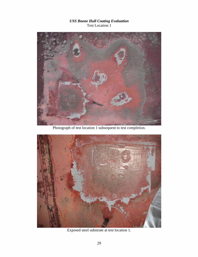
USS Boone Hull Coating Evaluation Test Location 1
Location Description Location 1 is on the keel, just starboard of the centerline, 2 feet forward of the stern air masker. It is located between blocks 15 and 16. The location is part of the underwater hull which would have been prepared with a hand lance. Blistering of the anticorrosive (epoxy) coating was observed in the area surrounding the test location. The blistering was liquid filled (pH ~12-13). Coating Thickness Summary
1 2 3 4 5 6 7 8 9 Total DFT 17.6 15.7 17.4 19.3 18.3 17.1 24.6 22.4 19.8 AC DFT 13.7 -- -- -- 11.7 -- 11.4 -- 10.7 AF DFT (Calculated) 3.9 -- -- -- 6.6 -- 13.2 -- 9.1
Instrument: Elcometer 246 S/N FE0084 (Field calibrated before use) Observations of Exposed Substrate Physical removal of the coating showed evidence that the coating was well adhered. Red primer was difficult to remove from the profile depths. Unburnished peaks had a brownish coloration, but there was no evidence of “loose” corrosion. Adhesion Test Data
Test Failure (psi) Failure Location 1-1 1270 70% primer cohesive, 15% primer/substrate, 15% glue 1-3 1335 70% primer cohesive, 25% primer/substrate, 5% glue 1-5 1708 55% primer cohesive, 20% primer/substrate, 25% glue 1-9 240 80% primer/substrate, 20% glue (note: adjacent to blisters)
Test Method: ASTM D4541 Instrument: Positest AT S/N AT02562 (Date of Calibration October 20, 2006) Electrical/Electrochemical Test Data Corrosion potential of exposed steel: 370 mV Capacitance measurements:
Location DFT Capacitance 1-1 13.7 mils 0.153 nF 1-3 11.7 mils 0.139 nF
Instrument: Metex Multimeter S/N 911395
28
USS Boone Hull Coating Evaluation Test Location 1
Photograph of test location 1 subsequent to test completion.
Exposed steel substrate at test location 1.
29
USS Boone Hull Coating Evaluation Test Location 2
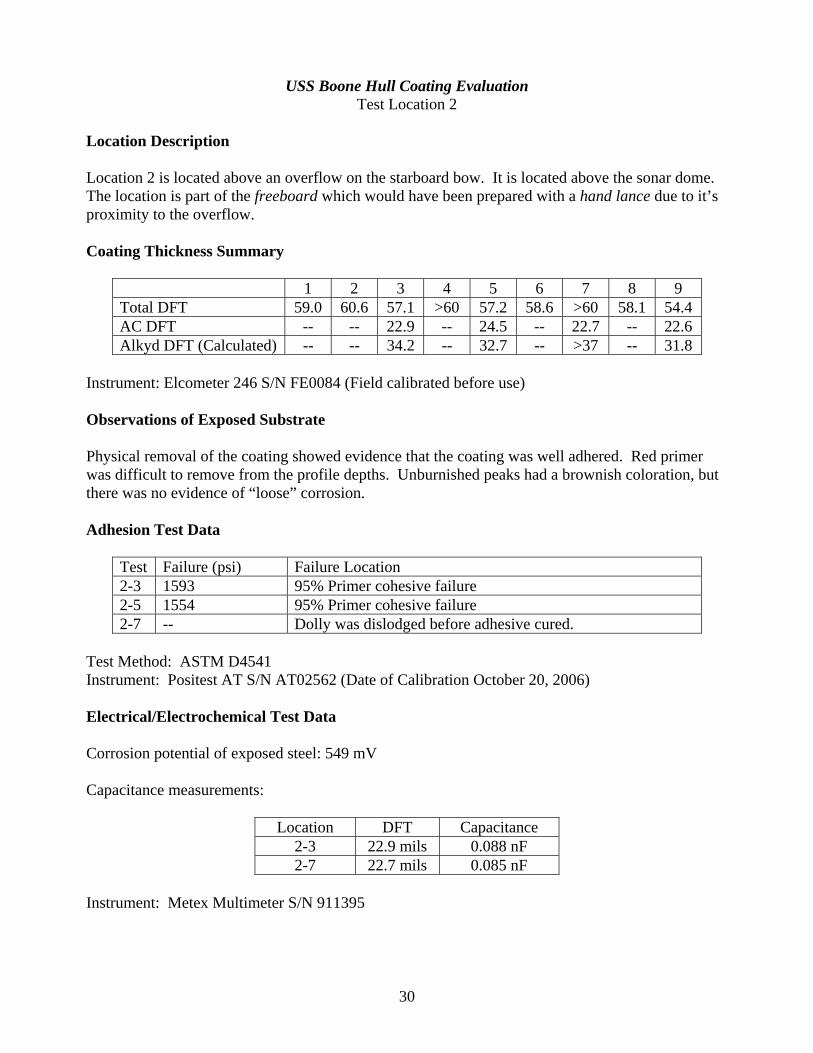
Location Description Location 2 is located above an overflow on the starboard bow. It is located above the sonar dome. The location is part of the freeboard which would have been prepared with a hand lance due to it’s proximity to the overflow. Coating Thickness Summary
1 2 3 4 5 6 7 8 9 Total DFT 59.0 60.6 57.1 >60 57.2 58.6 >60 58.1 54.4 AC DFT -- -- 22.9 -- 24.5 -- 22.7 -- 22.6 Alkyd DFT (Calculated) -- -- 34.2 -- 32.7 -- >37 -- 31.8
Instrument: Elcometer 246 S/N FE0084 (Field calibrated before use) Observations of Exposed Substrate Physical removal of the coating showed evidence that the coating was well adhered. Red primer was difficult to remove from the profile depths. Unburnished peaks had a brownish coloration, but there was no evidence of “loose” corrosion. Adhesion Test Data
Test Failure (psi) Failure Location 2-3 1593 95% Primer cohesive failure 2-5 1554 95% Primer cohesive failure 2-7 -- Dolly was dislodged before adhesive cured.
Test Method: ASTM D4541 Instrument: Positest AT S/N AT02562 (Date of Calibration October 20, 2006) Electrical/Electrochemical Test Data Corrosion potential of exposed steel: 549 mV Capacitance measurements:
Location DFT Capacitance 2-3 22.9 mils 0.088 nF 2-7 22.7 mils 0.085 nF
Instrument: Metex Multimeter S/N 911395
30

USS Boone Hull Coating Evaluation Test Location 2
Photograph of test location 2 subsequent to test completion.
Exposed steel substrate at test location 2.
31

USS Boone Hull Coating Evaluation Test Location 3
Location Description Location 3 is located slightly higher and aft of location 2. It is located above the sonar dome. The location is part of the freeboard which would have been prepared with a closed loop UHP robot. Coating Thickness Summary
1 2 3 4 5 6 7 8 9 Total DFT 59.0 56.5 55.5 >60 >60 59.4 >60 >60 >60 AC DFT -- -- 24.4 -- 30.0 -- 29.1 -- 22.6 AF DFT (Calculated) -- -- 31.1 -- >30 -- >31 -- >37
Instrument: Elcometer 246 S/N FE0084 (Field calibrated before use) Observations of Exposed Substrate Physical removal of the coating showed evidence that the coating was well adhered. Red primer was difficult to remove from the profile depths. Unburnished peaks had a brownish coloration, but there was no evidence of “loose” corrosion. Adhesion Test Data
Test Failure (psi) Failure Location 3-3 1711 75% Primer cohesive failure, remainder glue & gray epoxy 3-5 1539 85% Primer cohesive failure, remainder glue & gray epoxy 3-7 1585 40% Primer cohesive failure, remainder glue & gray epoxy
Test Method: ASTM D4541 Instrument: Positest AT S/N AT02562 (Date of Calibration October 20, 2006) Electrical/Electrochemical Test Data Corrosion potential of exposed steel: 540 mV Capacitance measurements:
Location DFT Capacitance 3-3 24.4 mils 0.082 nF 3-7 29.1 mils 0.074 nF
Instrument: Metex Multimeter S/N 911395
32
USS Boone Hull Coating Evaluation Test Location 3
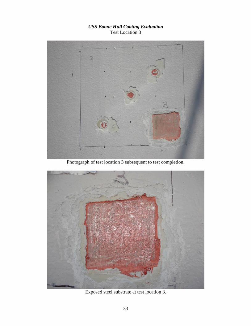
Photograph of test location 3 subsequent to test completion.
Exposed steel substrate at test location 3.
33
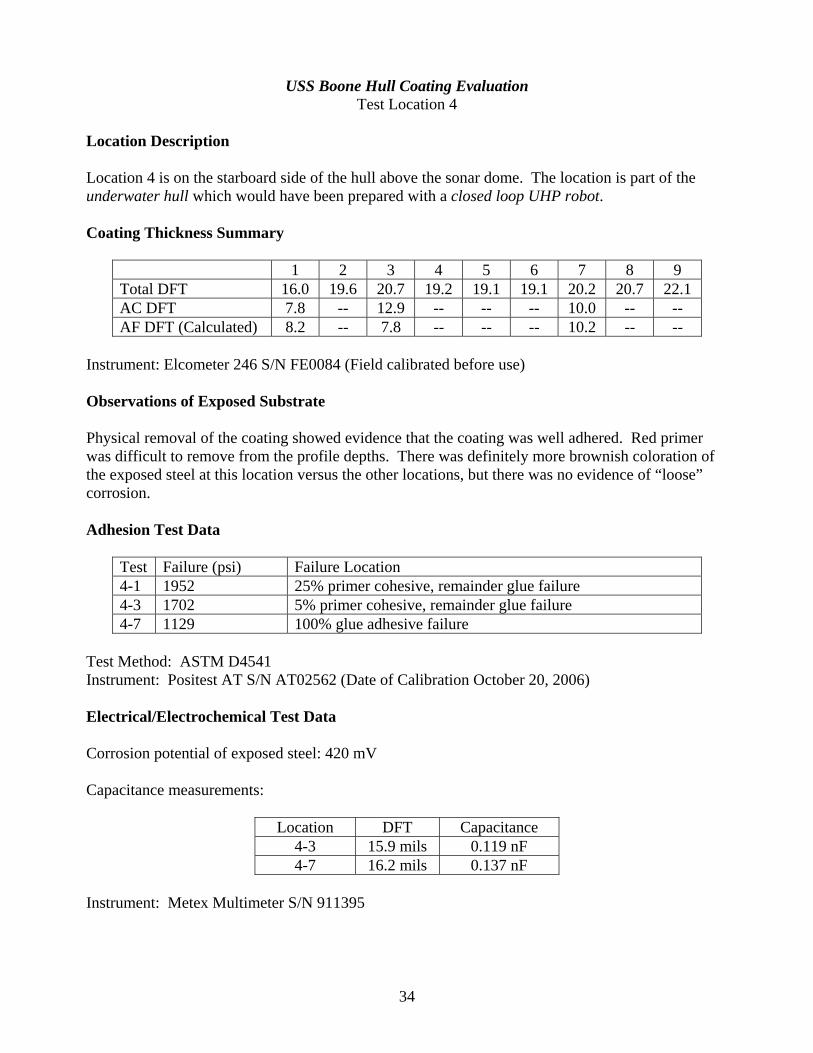
USS Boone Hull Coating Evaluation Test Location 4
Location Description Location 4 is on the starboard side of the hull above the sonar dome. The location is part of the underwater hull which would have been prepared with a closed loop UHP robot. Coating Thickness Summary
1 2 3 4 5 6 7 8 9 Total DFT 16.0 19.6 20.7 19.2 19.1 19.1 20.2 20.7 22.1 AC DFT 7.8 -- 12.9 -- -- -- 10.0 -- -- AF DFT (Calculated) 8.2 -- 7.8 -- -- -- 10.2 -- --
Instrument: Elcometer 246 S/N FE0084 (Field calibrated before use) Observations of Exposed Substrate Physical removal of the coating showed evidence that the coating was well adhered. Red primer was difficult to remove from the profile depths. There was definitely more brownish coloration of the exposed steel at this location versus the other locations, but there was no evidence of “loose” corrosion. Adhesion Test Data
Test Failure (psi) Failure Location 4-1 1952 25% primer cohesive, remainder glue failure 4-3 1702 5% primer cohesive, remainder glue failure 4-7 1129 100% glue adhesive failure
Test Method: ASTM D4541 Instrument: Positest AT S/N AT02562 (Date of Calibration October 20, 2006) Electrical/Electrochemical Test Data Corrosion potential of exposed steel: 420 mV Capacitance measurements:
Location DFT Capacitance 4-3 15.9 mils 0.119 nF 4-7 16.2 mils 0.137 nF
Instrument: Metex Multimeter S/N 911395
34

USS Boone Hull Coating Evaluation Test Location 4
Photograph of test location 4 subsequent to test completion.
Exposed steel substrate at test location 4.
35

USS Boone Hull Coating Evaluation Test Location 5
Location Description Location 5 is located on the starboard side of the sonar dome. The location is part of the underwater hull which would have been prepared with a hand lance. Coating Thickness Summary
1 2 3 4 5 6 7 8 9 Total DFT 22.4 20.9 19.1 22.9 20.7 18.9 21.6 17.8 19.0 AC DFT 19.8 -- 13.2 -- -- -- 18.4 -- -- AF DFT (Calculated) 2.6 -- 5.9 -- -- -- 3.2 -- --
Instrument: Elcometer 246 S/N FE0084 (Field calibrated before use) Observations of Exposed Substrate Physical removal of the coating showed evidence that the coating was well adhered. This location was the easiest to remove red primer from the profile depths. There was no evidence of “loose” corrosion. Adhesion Test Data
Test Failure (psi) Failure Location 5-1 1033 100% adhesive failure of the glue 5-3 605 100% adhesive failure of the glue 5-7 836 100% adhesive failure of the glue
Test Method: ASTM D4541 Instrument: Positest AT S/N AT02562 (Date of Calibration October 20, 2006) Electrical/Electrochemical Test Data Corrosion potential of exposed steel: 421 mV Capacitance measurements:
Location DFT Capacitance 5-3 13.4 mils 0.142 nF 5-7 20.7 mils 0.107 nF
Instrument: Metex Multimeter S/N 911395
36

USS Boone Hull Coating Evaluation Test Location 5
Photograph of test location 5 subsequent to test completion.
Exposed steel substrate at test location 5.
37

USS Boone Hull Coating Evaluation Test Location 6
Location Description Location 6 is located above the starboard bilge keel. It is located above block 33. The location is part of the underwater hull which would have been prepared with a closed loop UHP robot. Coating Thickness Summary
1 2 3 4 5 6 7 8 9 Total DFT 11.5 13.4 17.3 14.0 15.2 14.5 13.7 15.2 13.5 AC DFT 8.5 -- 15.1 -- -- -- 8.7 -- -- AF DFT (Calculated) 3.0 -- 2.2 -- -- -- 5.0 -- --
Instrument: Elcometer 246 S/N FE0084 (Field calibrated before use) Observations of Exposed Substrate Physical removal of the coating showed evidence that the coating was well adhered. Red primer was difficult to remove from the profile depths. Unburnished peaks had a brownish coloration, but there was no evidence of “loose” corrosion. Note that the extensive shiny areas in the photo are due to mechanical coating removal. Adhesion Test Data
Test Failure (psi) Failure Location 6-1 1376 5% primer cohesive, remainder adhesive glue failure 6-3 1608 40% primer cohesive, remainder adhesive glue failure 6-7 1179 100% adhesive glue failure
Test Method: ASTM D4541 Instrument: Positest AT S/N AT02562 (Date of Calibration October 20, 2006) Electrical/Electrochemical Test Data Corrosion potential of exposed steel: 425 mV Capacitance measurements:
Location DFT Capacitance 6-1 8.7 mils 0.161 nF 6-3 12.9 mils 0.144 nF
Instrument: Metex Multimeter S/N 911395
38

USS Boone Hull Coating Evaluation Test Location 6
Photograph of test location 6 subsequent to test completion.
Exposed steel substrate at test location 6.
39

USS Boone Hull Coating Evaluation Test Location 7
Location Description Location 7 is on the starboard bilge keel. It is located above block 33. The location is part of the underwater hull which would have been prepared with a hand lance. Coating Thickness Summary
1 2 3 4 5 6 7 8 9 Total DFT 15.6 16.7 16.0 17.9 17.1 17.4 18.4 17.5 17.8 AC DFT 6.1 -- 8.2 -- -- -- 8.2 -- -- AF DFT (Calculated) 9.5 -- 7.8 -- -- -- 10.2 -- --
Instrument: Elcometer 246 S/N FE0084 (Field calibrated before use) Observations of Exposed Substrate Physical removal of the coating showed evidence that the coating was well adhered. Red primer was difficult to remove from the profile depths. Unburnished peaks had a brownish coloration, but there was no evidence of “loose” corrosion. Adhesion Test Data
Test Failure (psi) Failure Location 7-1 1337 <5% primer cohesive, remainder adhesive glue failure 7-3 1344 75% primer cohesive, remainder adhesive glue failure 7-7 979 10% primer cohesive, remainder adhesive glue failure
Test Method: ASTM D4541 Instrument: Positest AT S/N AT02562 (Date of Calibration October 20, 2006) Electrical/Electrochemical Test Data Corrosion potential of exposed steel: 471 mV Capacitance measurements:
Location DFT Capacitance 7-5 13.2 mils 0.225 nF 7-7 13.3 mils 0.216 nF
Instrument: Metex Multimeter S/N 911395
40

USS Boone Hull Coating Evaluation Test Location 7
Photograph of test location 7 subsequent to test completion.
Exposed steel substrate at test location 7.
41

USS Boone Hull Coating Evaluation Test Location 8
Location Description Location 8 is on the starboard side of the skeg. It is located above block 5. The location is part of the underwater hull which would have been prepared with a hand lance. Coating Thickness Summary
1 2 3 4 5 6 7 8 9 Total DFT 19.2 21.8 25.0 16.6 21.2 24.7 17.2 23.3 26.2 AC DFT 12.9 -- 18.1 -- -- -- 11.9 -- -- AF DFT (Calculated) 6.3 -- 6.9 -- -- -- 5.3 -- --
Instrument: Elcometer 246 S/N FE0084 (Field calibrated before use) Observations of Exposed Substrate Physical removal of the coating showed evidence that the coating was well adhered in all but two small areas comprising 0.25 in² (2% of the surface). Over the majority of the surface, red primer was difficult to remove from the profile depths. Unburnished peaks had a brownish coloration, but there was no evidence of “loose” corrosion. Attached photographs show the locations where the coating was mechanically removed and a close-up of the surface after cleaning. Adhesion Test Data
Test Failure (psi) Failure Location 8-1 1364 40% primer cohesive, remainder adhesive glue failure 8-3 1028 100% adhesive glue failure 8-7 1331 100% adhesive glue failure
Test Method: ASTM D4541 Instrument: Positest AT S/N AT02562 (Date of Calibration October 20, 2006) Electrical/Electrochemical Test Data Corrosion potential of exposed steel: 401 mV Capacitance measurements:
Location DFT Capacitance 8-3 16.7 mils 0.102 nF 8-7 24.5 mils 0.135 nF
Instrument: Metex Multimeter S/N 911395
42

USS Boone Hull Coating Evaluation Test Location 8
Photograph of test location 8 subsequent to test completion.
Mechanically exposed steel substrate at test location 8 – note
two locations where corrosion is exposed.
43

USS Boone Hull Coating Evaluation Test Location 8
Exposed steel substrate at test location 8.
Close-up view of corrosion under the film at test location 8.
44

USS Samuel B. Roberts Hull Coating Evaluation Test Location 1
Location Description Location 1 is located on the port side of the sonar dome, approximately in the center. The location is part of the underwater hull which would have been prepared with a hand lance. Coating Thickness Summary
1 2 3 4 5 6 Avg Std DevAC DFT 11.8 14.6 14.5 13.4 15.1 15.8 14.2 1.42 Total DFT 26.0 26.7 20.7 23.4 25.6 28.4 25.1 2.71
Estimated AF DFT – 10.9 mils Instrument: Elcometer 246 S/N FE0084 (Field calibrated before use) Observations of Exposed Substrate Testing of this area did not include exposing the steel substrate using chemical stripper. However, the substrate was exposed as a result of the pull-off adhesion tests. At the test locations, brown rust was evident under the primer. The primer was well bonded to the substrate, exhibiting adhesion values in excess of 1100 psi. Adhesion Test Data
Test Failure Failure Location 1-1 1127 psi 85% primer/substrate, 15% within gray AC 1-2 1251 psi 100% primer/substrate 1-3 1355 psi 100% primer/substrate
Test Method: ASTM D4541 Instrument: Positest AT S/N AT02562 (Date of Calibration October 20, 2006) Electrical/Electrochemical Test Data Corrosion potential of exposed steel: 380.2 mV at pull-off adhesion location 1-2 (center). Capacitance measurement: 0.129 nF, DFT 14.6 mils Instrument: Metex Multimeter S/N 911395
45

USS Samuel B. Roberts Hull Coating Evaluation Test Location 1
Photograph of test location 1 subsequent to test completion.
Close-up of adhesion tests at test location 1.
46

USS Samuel B. Roberts Hull Coating Evaluation
Test Location 2 Location Description Location 2 is located on the port side above the sonar dome. The location is part of the underwater hull which would have been prepared with a closed loop UHP robot. Coating Thickness Summary
1 2 3 4 5 6 Avg Std DevAC DFT 9.7 12.1 11.7 12.6 11.2 13.6 11.8 1.32 Total DFT 24.5 26.7 24.3 25.8 26.8 26.6 25.8 1.13
Estimated AF DFT – 14.0 mils Instrument: Elcometer 246 S/N FE0084 (Field calibrated before use) Observations of Exposed Substrate Testing of this area did not include exposing the steel substrate. Adhesion Test Data
Test Failure Failure Location 2-1 1300 psi 100% within gray epoxy 2-2 1547 psi 100% within gray epoxy 2-3 1445 psi 100% within gray epoxy
Test Method: ASTM D4541 Instrument: Positest AT S/N AT02562 (Date of Calibration October 20, 2006) Electrical/Electrochemical Test Data Corrosion potential of exposed steel: Not measured/no exposed substrate Capacitance measurement: 0.135 nF, DFT 12.1 mils Instrument: Metex Multimeter S/N 911395
47

USS Samuel B. Roberts Hull Coating Evaluation Test Location 2
Photograph of test location 2 subsequent to test completion.
Close-up of adhesion tests at test location 2.
48

USS Samuel B. Roberts Hull Coating Evaluation
Test Location 3 Location Description Location 3 is located on the port side, just aft of block 41, a few feet outboard of the keel. The location is part of the underwater hull which would have been prepared with a hand lance. Coating Thickness Summary
1 2 3 4 5 6 Avg Std DevAC DFT 6.2 11.2 6.2 10.9 7.2 10.9 8.8 2.48 Total DFT 23.3 28.3 22.0 25.7 25.0 22.8 24.5 2.31
Estimated AF DFT – 15.8 mils Instrument: Elcometer 246 S/N FE0084 (Field calibrated before use) Observations of Exposed Substrate Physical removal of the coating showed further evidence that the primer was well adhered to a sound substrate. The primer was difficult to clean from the depths of the profile. A stripe of stain was observed through the center of the exposed steel. After further review of the stain, it was observed that the stain lined up with a streak of blisters that continued up to an overboard discharge. The type of discharge was not determined, but it is probable that the dark staining is associated with the discharge rather than an anomaly related to flash rust associated with hand-lance surface preparation. Adhesion Test Data
Test Failure Failure Location 3-1 1968 psi 55% substrate, 20% gray epoxy, 25% red primer 3-2 2244 psi 95% gray epoxy, 5% red primer 3-3 1809 psi 65% substrate, 25% gray epoxy, 10% red primer
Test Method: ASTM D4541 Instrument: Positest AT S/N AT02562 (Date of Calibration October 20, 2006) Electrical/Electrochemical Test Data Corrosion potential of exposed steel: 362 mV at pull-off adhesion location 3-1 Capacitance measurement: 0.152 nF, DFT 11.2 mils Instrument: Metex Multimeter S/N 911395
49

USS Samuel B. Roberts Hull Coating Evaluation Test Location 3
Photograph of test location 3 subsequent to test completion.
Close-up of adhesion tests at test location 3.
50

USS Samuel B. Roberts Hull Coating Evaluation
Test Location 4 Location Description Location 4 is located on the port side, just aft of block 41, a few feet below the bootstripe. The location is part of the underwater hull which would have been prepared with a closed loop UHP robot. Coating Thickness Summary
1 2 3 4 5 6 Avg Std DevAC DFT 13.3 12.9 11.5 10.3 10.9 11.1 11.7 1.18 Total DFT 27.5 28.1 23.2 22.7 23.9 25.1 25.1 2.26
Estimated AF DFT – 13.4 mils Instrument: Elcometer 246 S/N FE0084 (Field calibrated before use) Observations of Exposed Substrate Physical removal of the coating showed further evidence that the primer was well adhered to a sound substrate. The primer was difficult to clean from the depths of the profile. The exposed steel had a definite anchor profile which visually appeared to exceed 1 mil. Adhesion Test Data
Test Failure Failure Location 4-1 1383 psi 100% gray epoxy 4-2 2453 psi 50% substrate, 35% red primer, 15% gray epoxy 4-3 2099 psi 90% gray epoxy, 5% substrate, 5% red primer
Test Method: ASTM D4541 Instrument: Positest AT S/N AT02562 (Date of Calibration October 20, 2006) Electrical/Electrochemical Test Data Corrosion potential of exposed steel: 398.1 mV at pull-off adhesion location 4-2 Capacitance measurement: 0.120 nF, DFT 12.9 mils Instrument: Metex Multimeter S/N 911395
51
USS Samuel B. Roberts Hull Coating Evaluation Test Location 4
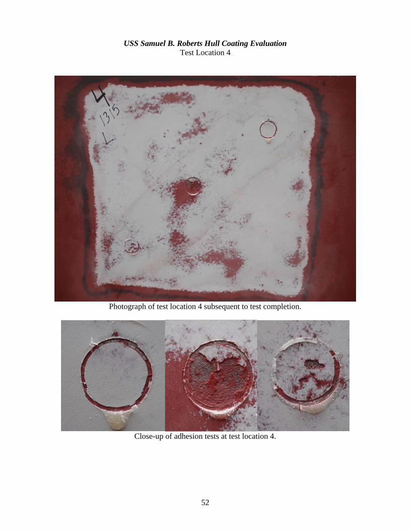
Photograph of test location 4 subsequent to test completion.
Close-up of adhesion tests at test location 4.
52

USS Samuel B. Roberts Hull Coating Evaluation
Test Location 5 Location Description Location 5 is located on the port bilge keel, approximately in the center. The location is part of the underwater hull which would have been prepared with a hand lance. Coating Thickness Summary
1 2 3 4 5 6 Avg Std DevAC DFT 8.1 8.4 9.5 9.7 9.7 10.6 9.3 0.93 Total DFT 24.8 22.3 23.4 22.4 25.4 24.9 23.9 1.40
Estimated AF DFT – 14.5 mils Instrument: Elcometer 246 S/N FE0084 (Field calibrated before use), no BMR correction Observations of Exposed Substrate Testing of this area did not include exposing the steel substrate. Adhesion Test Data
Test Failure Failure Location 5-1 1140 psi 100% gray epoxy 5-2 1593 psi 100% gray epoxy 5-3 1682 psi 100% gray epoxy
Test Method: ASTM D4541 Instrument: Positest AT S/N AT02562 (Date of Calibration October 20, 2006) Electrical/Electrochemical Test Data Corrosion potential of exposed steel: not measured (no exposed substrate) Capacitance measurement: 0.166 nF, DFT 8.4 mils Instrument: Metex Multimeter S/N 911395
53

USS Samuel B. Roberts Hull Coating Evaluation Test Location 5
Photograph of test location 5 subsequent to test completion.
Close-up of adhesion tests at test location 5.
54

USS Samuel B. Roberts Hull Coating Evaluation
Test Location 6 Location Description Location 6 is located on the port side, above the bilge keel (around block 30), a few feet below the bootstripe. The location is part of the underwater hull which would have been prepared with a closed loop UHP robot. Coating Thickness Summary
1 2 3 4 5 6 Avg Std DevAC DFT 14.4 12.8 11.0 11.7 11.5 10.9 12.1 1.34 Total DFT 20.7 19.0 22.8 20.0 21.4 19.4 20.6 1.40
Estimated AF DFT – 8.5 mils Instrument: Elcometer 246 S/N FE0084 (Field calibrated before use) Observations of Exposed Substrate Testing of this area did not include exposing the steel substrate. Adhesion Test Data
Test Failure Failure Location 6-1 1984 psi 100% in gray epoxy 6-2 1572 psi 100% in gray epoxy 6-3 1904 psi 100% in gray epoxy
Test Method: ASTM D4541 Instrument: Positest AT S/N AT02562 (Date of Calibration October 20, 2006) Electrical/Electrochemical Test Data Corrosion potential of exposed steel: not measured (no exposed steel) Capacitance measurement: 0.131 nF, DFT 14.4 mils Instrument: Metex Multimeter S/N 911395
55

USS Samuel B. Roberts Hull Coating Evaluation Test Location 6
Photograph of test location 6 subsequent to test completion.
Close-up of adhesion tests at test location 6.
56

USS Samuel B. Roberts Hull Coating Evaluation
Test Location 7 Location Description Location 7 is located on the port side, aft of the stabilizer fin, a few feet below the boottop. The location is part of the underwater hull which would have been prepared with a closed loop UHP robot. Coating Thickness Summary
1 2 3 4 5 6 Avg Std DevAC DFT 12.0 11.5 9.3 8.7 9.3 9.7 10.1 1.34 Total DFT 32.1 26.1 19.2 22.4 25.3 23.0 24.7 4.37
Estimated AF DFT – 14.6 mils Instrument: Elcometer 246 S/N FE0084 (Field calibrated before use) Observations of Exposed Substrate Testing of this area did not include exposing the steel substrate using chemical stripper. However, the substrate was exposed as a result of the pull-off adhesion tests. At the test locations, clean steel was observed where the primer had disbonded. Primer was adhered to small, scattered locations of the exposed steel.. The primer was well bonded to the substrate, exhibiting adhesion values in excess of 1100 psi. Adhesion Test Data
Test Failure Failure Location 7-1 1945 psi 90% substrate, 10% gray epoxy 7-2 1119 psi 60% substrate, 40% gray epoxy 7-3 2183 psi 90% substrate, 10% gray epoxy
Test Method: ASTM D4541 Instrument: Positest AT S/N AT02562 (Date of Calibration October 20, 2006) Electrical/Electrochemical Test Data Corrosion potential of exposed steel: 397 mV at pull-off adhesion location 7-1 Capacitance measurement: 0.149 nF, DFT 11.5 mils Instrument: Metex Multimeter S/N 911395
57

USS Samuel B. Roberts Hull Coating Evaluation Test Location 7
Photograph of test location 7 subsequent to test completion.
Close-up of adhesion tests at test location 7.
58

USS Samuel B. Roberts Hull Coating Evaluation
Test Location 8 Location Description Location 8 is located on the port side, aft and inboard of the stabilizer. The location is part of the underwater hull which would have been prepared with a hand lance. Coating Thickness Summary
1 2 3 4 5 6 Avg Std DevAC DFT 10.3 13.4 7.4 12.9 6.3 10.7 10.2 2.86 Total DFT 30.0 36.0 26.8 26.6 25.9 26.8 28.7 3.86
Estimated AF DFT – 18.5 mils Instrument: Elcometer 246 S/N FE0084 (Field calibrated before use) Observations of Exposed Substrate Testing of this area did not include exposing the steel substrate using chemical stripper. However, the substrate was exposed as a result of the pull-off adhesion tests. At the test locations, brown rust was evident at points where the primer had disbonded. Red primer still adhered to the surface around the points of rust. The primer was well bonded to the substrate, exhibiting adhesion values in excess of 2000 psi. Adhesion Test Data
Test Failure Failure Location 8-1 2032 psi 33% substrate, 67% primer 8-2 2071 psi 50% substrate, 40% primer, 10% gray epoxy 8-3 2389 psi 95% gray epoxy, 5% substrate
Test Method: ASTM D4541 Instrument: Positest AT S/N AT02562 (Date of Calibration October 20, 2006) Electrical/Electrochemical Test Data Corrosion potential of exposed steel: 371.8 mV at pull-off adhesion location 8-2 Capacitance measurement: 0.133 nF, DFT 13.4 mils Instrument: Metex Multimeter S/N 911395
59

USS Samuel B. Roberts Hull Coating Evaluation Test Location 8
Photograph of test location 8 subsequent to test completion.
Close-up of adhesion tests at test location 8.
60

Appendix C – Detailed Round Robin Results The following figures summarize the results of each panel in the round robin test. The figures are sorted in order from the panel with the lowest average rating to the highest average rating. The title contains the panel number and the average rating for the panel (1 = no flash rust, 2 = Light, 3 = Moderate, and 4 = Heavy). The graph in the upper right of each figure shows the percentage of participants providing each rating. The photograph in the upper left is an overall view of the test panel which includes the visual standard (Initial Condition C) for reference. The photograph in the lower right was taken using a digital camera with consistent lighting (ring flash) and magnification (note the ruler in the bottom of each photograph). The language in the lower left describes how the test panel was prepared.
61

62

63

64

65