rev 1.3installation and operation propac propac 10...
TRANSCRIPT

IDS-120 96 IDS-120 80 IDS-120 64 IDS-80 64 IDS-80 52 IDS-80 40 IDS-65 32 IDS-50 26,32
This Manual Contains:
Installation Instructions Operating Instructions
Maintenance Procedures Safety Precautions
PLEASE READ THIS ENTIRE MANUAL BEFORE BEGINNING INSTALLATION OR
ATTEMPTING TO OPERATE THIS SYSTEM
PROPAC™
10 D
REV 1.3
All Safety Precautions are posted as WARNINGS or CAUTIONS in text boxes.
IDS 10 240 PP 120
Installation and Operation Manual for PROPAC™ 10 D
Integrated Drainback System Numbers:
FIGURE 1
Cold Supply “In”
Hot Water “Out” to Dwelling Controller
To Collector(s)
From Collector(s) Collectors
Isolation Ball Valves
Cold Water “Shut Off “Valve Controller
Mixing Valve
Back up Heating Element
ProPac Solar Control
Sight Glass
Temperature & Pressure Relief Valve
To Storage Tank
From Storage Tank
Water Heater Storage Tank
Catch or Drip Pan
Drain Valve
Drain Valve
Return line ball valve
REV 1.3 2
FIGURE 2
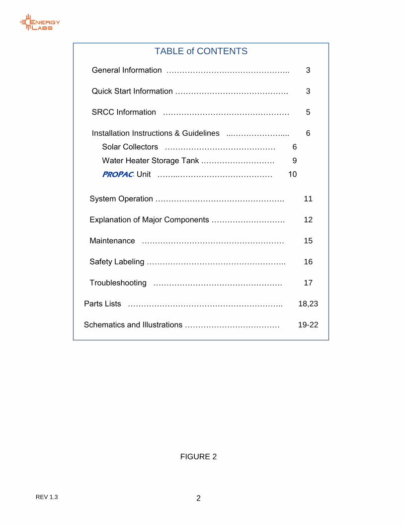
TABLE of CONTENTS
General Information ……………………………………….. 3
Quick Start Information ……………………………………. 3
SRCC Information ………………………………………… 5
Installation Instructions & Guidelines ...……………….... 6
Solar Collectors …………………………………… 6
Water Heater Storage Tank .……………………… 9
PROPAC™ Unit ……..……………………………… 10
System Operation …………………………………………. 11
Explanation of Major Components ………………………. 12
Maintenance ……………………………………………… 15
Safety Labeling …………………………………………….. 16
Troubleshooting …………………………………………. 17
Parts Lists ………………………………………………….. 18,23
Schematics and Illustrations ……………………………… 19-22
CONGRATULATIONS!
Yo
REV 1.3 3
E
ne
rgy fo
r a c
ha
ng
ing
wo
rld
General Information
The installation of solar water heating systems should only be undertaken by qualified individuals. Solar water heating systems involve components and operating principles not found in standard plumbing installations. High operating temperatures, alternate fluids and unusual plumbing techniques are an integral part of solar systems. Failure to understand good installation practices can affect the health and safety of the end user. Poor practices will also reduce system performance. In many areas a certified licensed installation contractor’s license is required for installation of solar water heating systems. Take time to research and get to know the installing contractor before allowing anyone to begin installation of the system components. It is highly recommended the contracting company be insured and bonded to work in private residences.
The PROPAC™ unit must be installed indoors, or
in an area that does not experience direct contact with the outside weather. This area must never experience temperatures at or below 32OF. The Warranty on the PROPAC™ unit is only in
effect when the system has been installed and operating in accordance with all Local Codes and the associated component manuals. The provider of this system will not be liable for any damage resulting from the improper installation and operation of the system. In the absence of Local Codes install the system in accordance with N.E.C. and IAPMO codes, latest editions.
Your solar system main components are made by different manufacturers. A separate Manufacturers Installation and Operations Manual is provided with the major components. This Manual is the main guide for installation for the complete system. The Water Heater Storage Tank and Solar Collectors have separate Manuals that must be used during the installation.
The PROPAC™10 D is sized to a particular heat
demand and collector surface area. It can move heat up to the rated BTU/Hr output listed. Make sure your system is sized properly for the PROPAC™ unit.
Quick Start Information
This Section gives a brief overview of the recommended steps that should be taken to install the PROPAC™ solar water heating system.
These are not detailed procedures and are only provided to establish initial steps that can be undertaken quickly to get the installation started.
LOCATION
Before all else, make sure the location for the major components has been established. This will eliminate unnecessary re-work later on. There are three major components to the system:
1. The Collector(s) 2. The Water Heater Storage Tank (WHST) 3. The PROPAC™ unit, sometimes referred to
as the Heat Transfer Unit or HTU
Most often, the location of the Water Heater Storage tank has been predetermined by the location of the existing storage tank. In some cases the existing storage tank may be used but, in general the old water heater will be replaced with a new WHST. Once this is determined, proceed to selecting the location for the collectors.
Select the best location for the collectors based on a clear unobstructed southern exposure trying to place the collectors as close to the Water Heater Storage Tank as possible.
The last step is to set the PROPAC™ unit. Once it
is set and plumbed, it can then be filled with distilled water per the instructions in this manual.
REV 1.3 4
LITERATURE Each system comes with a bag containing all information available on the various parts and components that make up the system. DO NOT attempt installation without this information. Contact your Energy Labs dealer or sales person immediately if it missing. INSTALLATION OVERVIEW The following steps are then ready to be taken. The final location for all three major components must be determined before beginning. 1. Install the Collectors in accordance with the
manufacturer’s written instructions. At this point you will be:
a. Mounting the collectors and ensuring proper draining
b. Installing flashings for the pipes and wire
c. Running pipes sloped down to the location above the PROPAC™ system.
d. Insulating and UV protecting all external piping and wiring
2. Set the WHST and install it according to
written instructions provided by the manufacturer.
a. Make plumbing connections to and from dwelling.
b. Make electrical connections c. Check all connections
3. Set and then install the PROPAC™ unit in
order with these general steps: a. Make the interconnections to the
PROPAC™ unit. This will include
isolation valves b. Connect the piping to and from the
collector(s) c. Check all connections d. Fill the WHST and check for leaks. e. Fill the PROPAC™ tank with
DISTILLED WATER per instructions in this manual
f. Apply power to the WHST or connected boiler.
g. Turn on power to the PROPAC™ unit.
h. Manually start the PROPAC™ system
and check to see the system is operating properly.

REV 1.3 5
E
ne
rgy fo
r a c
ha
ng
ing
wo
rld
Systems described in this manual have been Rated and Certified by the Solar Rating and Certification Corporation, SRCC. If the system being installed requires an SRCC Rating and Certification for any reason, the system must be in the list below and installed with all criteria in this manual being met. Only those systems listed in the Label below are Rated and Certified by SRCC. All Collector Models installed for these systems must have the SRCC OG100 Certification and Rating.
THIS SPACE FOR SRCC OG300 LABEL INSERTION

REV 1.3 6
Installation Instructions Installation of solar water heating systems should only be undertaken by qualified individuals. Solar water heating systems involve components and operating principles not found in standard household plumbing installations. High operating temperatures, alternate fluids and unusual plumbing techniques are an integral part of solar systems. Failure to understand good installation practices can affect the health and safety of the end user. Poor practices may also reduce system performance.
Solar Collector Location and Installation Guidelines
General rule of thumb on placement: if you're in the northern hemisphere, then the collectors should face south. If you're in the southern hemisphere, the collectors should face north.
PROPAC™ systems by Energy Labs are approved
for use with only SRCC OG100 certified collector brands. The list below contains the brands that may be installed with these systems:
AET
APRICUS
CHROMAGEN
HELIODYNE
SILICON SOLAR
SOLAR HOT
SUN EARTH
SYNERGY SOLAR
Consult the collector manufacturers’ Installation & Operating instructions before attempting to install the collectors. Following are general guidelines for the installation of flat plate solar collectors.
Collector Orientation
The performance of solar water heating systems in the Northern Hemisphere is optimized when the collector is mounted facing True South. Performance output suffers when collectors are oriented more than 30° East or West of True South. The collector should be un-shaded by any permanent obstacle between 9:00 a.m. and 3:00 p.m. on any day of the year.
Collector Tilt Optimal annual efficiency is achieved by tilting the solar collector at an angle that equals your latitude plus an additional 10°. This tilt angle favors the lower winter sun when collector performance is at its lowest and minimizes overheating during the hottest summer months. The solar collectors in a staggered mount installation must be spaced far enough apart to prevent winter shading. The correct spacing between collectors should be sufficient to prevent shading on December 21
st, when the sun is at its lowest angle. See (figure
3). A general winter sun angle formula for northern hemisphere locations follows:
Winter sun angle (angle from horizon to sun)
Angle = (90 - Latitude) - 23.5
Basic Mounting Procedures
The solar collectors for your PROPAC™ Drainback
system should only be mounted in a vertical orientation on the roof (Figures 4&5). Because the freeze protection method is Drainback the collector must always be mounted in vertical orientation to prevent trapped pockets of water. Horizontal orientation may also void collector warranties. (See figure 4). It is important to slope the collectors just slightly toward the inlet to allow for complete drainage during off mode. This is required in freezing environments to prevent trapped water from freezing inside the collectors. The required slope is at least 1/4" vertical rise per foot of horizontal run.
CAUTION: Mounting collectors with the parallel flow tubes in the horizontal position is not allowed. See figure 4.
!DO NOT SKIP ANY INSTRUCTIONS! Read the entire Manual before
proceeding
Figure 3

REV 1.3 7
E
ne
rgy fo
r a c
ha
ng
ing
wo
rld
The solar collector should be mounted on the roof in accordance with the following general principles: The most important structural consideration is to securely anchor the solar collector and the associated mounting hardware to the structural members of the roof with stainless steel hanger or lag bolts. The solar collector must be attached to the mounting hardware as detailed in Collector Manufacturers’ I&O Manuals. Collectors must be raised from the roof surface to allow for rainwater and debris to pass under the collectors and for proper ventilation of the roofing material. There should be at least 1 1/2" of clearance between the roof surface and the bottom of the solar collectors.
In selecting mounting hardware and fasteners it is extremely important to avoid galvanic corrosion resulting from the direct contact of incompatible metals. Use of powder coated or anodized aluminum mounting hardware and stainless steel lag or hanger bolts, lock washers and round washers are recommended. In climates subject to severe winters, salt spray, or high humidity, the use of galvanized fasteners is prohibited. Preserving the integrity of the roof membrane is the most important roofing consideration. Ensure that all roof penetrations required to plumb and mount the solar collector are properly flashed and sealed in accordance with standard roofing practices. Tremco "POLYROOF" is the recommended elastomer for sealing roof penetrations. Henry Co. 204, 208 or 209 roof mastic or Dow Corning Glazing Sealant and Sikaflex are also are acceptable sealants. If the region is subject to hurricane conditions, additional steps may be required to secure the collector and mounting hardware to the structural members. In certain areas of the country, local building codes may require collector wind load testing or prescribe specific mounting procedures.
Collector Plumbing
Energy Labs PROPAC™ systems require the use of
all copper and/or brass fittings in the collector array plumbing. Couplings rather than unions should be used to join the collectors to avoid leaks and fluid loss. Use only lead-free solder. Use of 95/05 or 50/50 lead solder is expressly prohibited. Use of galvanized steel, CPVC, PVC, or plastic pipe other than PEX is prohibited. PEX tube is SRCC approved for all non-pressurized drainback systems. If PEX is used, a 60” copper transition pipe from the return side of the collectors and a 24” copper transition pipe on the feed side of the collector are required before connecting PEX. The minimum size for the “To” and “From” collector piping is 3/4”.
NOTE: PEX tube is not rigid. When using PEX, the tubing should be supported sufficiently to insure there are no low areas along the length of the run. A low area may allow water to collect and present a freezing or a dangerous over-temp condition.
Figure 4
Figure 5

REV 1.3 8
Interconnect Plumbing Piping “To” and “From” the solar collector array and the hot water storage tank is called the solar array interconnect plumbing. Because this solar system is a drainback Type it requires minimal fittings. An important rule in drainback systems is that the interconnect plumbing to the collectors must slope from the collectors back to the drainback reservoir with no change in the slope that would cause water to stay in the lines when the pump is not running. All vertical piping between the storage tank and the collector shall be supported at each story or at maximum intervals of ten (10) feet. Copper plumbers tape or tube strap is required. The pipe insulation may not be compressed or crimped by the strapping material.
Soft copper or PEX tubing can be run in the attic or plenum to the point where the piping will transition through the roof. The entire length of the piping should be insulated. Remember: Collectors and all solar array interconnect piping must slope downward from the collectors to the DBX unit with at least ¼” per foot of length.
DO NOT INSTALL THE “TO” and “FROM”
COLLECTOR LINES INTO THE PROPAC™ UNIT AT
THIS TIME.
Collector Loop Pipe Insulation The collector loop cold supply and hot return lines must be well insulated with high quality flexible closed cell insulation to minimize heat loss. The wall thickness of the pipe insulation should not be less than 3/4". A 1" wall thickness is required in all areas prone to annual hard freeze conditions. When it comes to pipe insulation the rule is simple: thicker is better. The specified insulation material is Rubatex Insul-Tube 180, Armaflex, K-Flex or equal brands. To the extent possible, slide the insulation material over the pipe without cutting or gluing. All butt joints must be sealed with contact adhesive. The use of rigid polyethylene pipe insulation is prohibited. The temperatures generated by your collector in the summer months or under stagnation conditions can melt this type of material. Any above ground exterior pipe insulation is subject to ultra-violet (UV) degradation. It must all be wrapped with foil tape or painted with two coats of UV protective water-based acrylic resin coating as supplied by the insulation manufacturer.
The installation of all horizontal and vertical piping may not reduce the performance or rating of any structural member or fire rated assembly. Adhere to all applicable local codes and ordinances.
Sensors The sensors for the Propac system are all internally prewired. Both sensors are attached to the heat exchanger and read the temperatures from the collector return and water storage while the water is circulating. Do not install any collector sensors with this system. The Steca contains 3 sensor ports, 2 of which are already used by this system. The third port (T3) can be used for an optional reading at the top of the tank. This sensor should be attached with a hose clamp to the hot water supply piping coming from the top of the tank and insulated adequately.
WARNING: THIS IS A DRAINBACK SYSTEM. ALL PLUMBING “TO” AND “FROM” COLLECTORS AND COLLECTORS THEMSELVES MUST BE SET SO THEY WILL DRAIN COMPLETELY WHEN THE SOLAR PUMP IS OFF. A MINIMUM OF ¼” OF DROP PER HORIZONTAL FOOT OF RUN IS MANDATORY.
REV 1.3 9
E
ne
rgy fo
r a c
ha
ng
ing
wo
rld
Sensor wire The low voltage wiring used to connect any optional sensor to the controller should be a minimum 18 AWG. The wiring should be copper or tinned copper, two-conductor, SHEIELDED TWISTED PAIR, PVC insulated, with a PVC UV rated jacket suitable for exterior use.
Water Heater Storage Tank Install the Water Heater Storage Tank (WHST) according to its installation instructions.
If the PROPAC™ unit is to be connected to a boiler
system there will be certain precautions that will need to be considered. One important rule when connecting to a Boiler tank or water heater is to make sure the water that is pulled from the storage tank is from the base of the tank and returned to a spot near the bottom of the tank or below the tanks temperature sensor in the boiler or water heater. This will eliminate “short cycling” of the boiler or water heater and allow for its normal operating cycle. It is important to be aware of the sensor’s location for the temperature control of the water heater, especially if it is a gas fired water heater. These sensors will feel a small pocket of cold water when the solar system first starts and will “short cycle” the water heater.
Water Heater or Boiler Storage Tank Sensors PROPAC™ system has the option for a sensor on the
WHST. An optional Top or Bottom of Tank sensor may be installed to read the temperature of the water in the tank. The sensors must be installed so they contact the bare metal tank which is underneath the insulation. Most water heaters use expanded foam for insulation. Wedging the sensor between the foam and tank is an acceptable procedure. Solar water heaters normally have two sensor lead wires that are hidden in the shroud and run from the top of the tank to a location behind the lower access panel. These should be used for the lower sensor to keep the installation aesthetically clean.
Some tanks have a stub bolt at the bottom of the tank for the sensor.
The top of tank sensor can be attached to the Hot Water out Line on top of the tank if it can be well insulated.
There is a Hot Water SCALD Potential if the thermostat is set too high and no tempering or mixing valve is installed.
Combination Thermostat-High Limit Control Some electric water heaters are equipped with a combination "Thermostat-High Limit Control" which is located just above the heating element. If for any reason the water temperature becomes excessively high, the "High Limit Control" breaks the circuit to the heating element. Once this switch opens, it must be manually reset. However, THE CAUSE OF THE OVER TEMPERATURE CONDITION MUST BE CORRECTED FIRST.
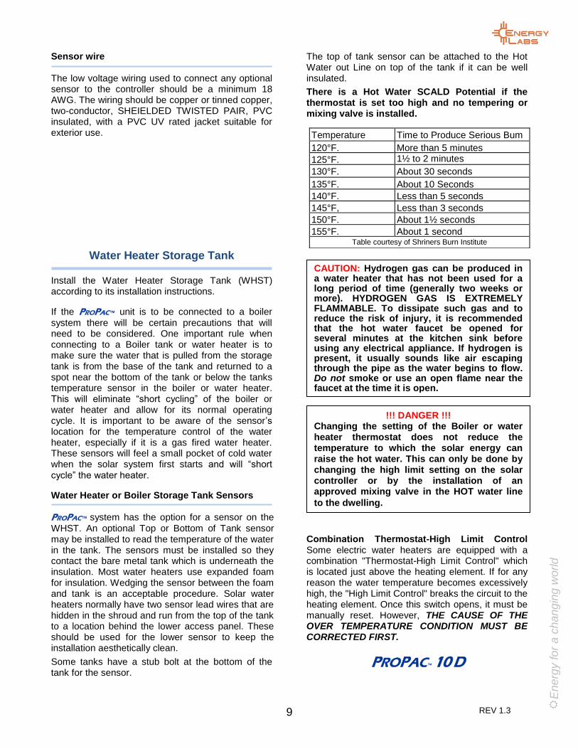
PROPAC™ 10 D
Temperature
Time to Produce Serious Bum
120°F.
More than 5 minutes
125°F.
1½ to 2 minutes
130°F.
About 30 seconds
135°F.
About 10 Seconds
140°F.
Less than 5 seconds
145°F,
Less than 3 seconds
150°F.
About 1½ seconds
155°F.
About 1 second
Table courtesy of Shriners Burn Institute
!!! DANGER !!! Changing the setting of the Boiler or water heater thermostat does not reduce the temperature to which the solar energy can raise the hot water. This can only be done by changing the high limit setting on the solar controller or by the installation of an approved mixing valve in the HOT water line
to the dwelling.
CAUTION: Hydrogen gas can be produced in a water heater that has not been used for a long period of time (generally two weeks or more). HYDROGEN GAS IS EXTREMELY FLAMMABLE. To dissipate such gas and to reduce the risk of injury, it is recommended that the hot water faucet be opened for several minutes at the kitchen sink before using any electrical appliance. If hydrogen is present, it usually sounds like air escaping through the pipe as the water begins to flow. Do not smoke or use an open flame near the faucet at the time it is open.
REV 1.3 10
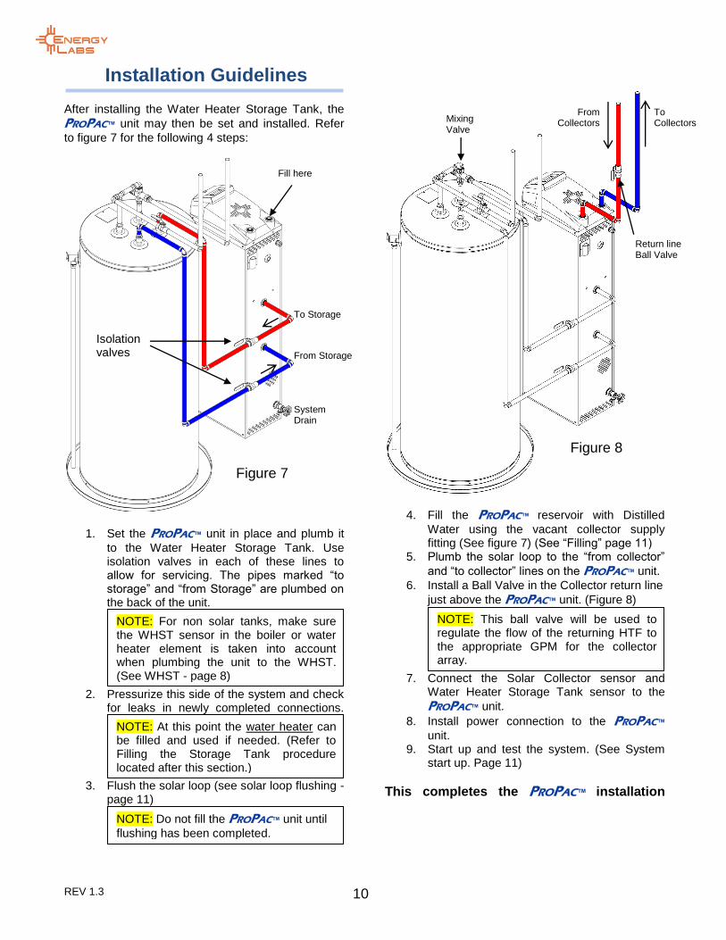
Installation Guidelines
After installing the Water Heater Storage Tank, the
PROPAC™ unit may then be set and installed. Refer
to figure 7 for the following 4 steps:
1. Set the PROPAC™ unit in place and plumb it
to the Water Heater Storage Tank. Use isolation valves in each of these lines to allow for servicing. The pipes marked “to storage” and “from Storage” are plumbed on the back of the unit.
2. Pressurize this side of the system and check
for leaks in newly completed connections.
3. Flush the solar loop (see solar loop flushing -
page 11)
4. Fill the PROPAC™ reservoir with Distilled
Water using the vacant collector supply fitting (See figure 7) (See “Filling” page 11)
5. Plumb the solar loop to the “from collector”
and “to collector” lines on the PROPAC™ unit.
6. Install a Ball Valve in the Collector return line
just above the PROPAC™ unit. (Figure 8)
7. Connect the Solar Collector sensor and
Water Heater Storage Tank sensor to the
PROPAC™ unit.
8. Install power connection to the PROPAC™
unit. 9. Start up and test the system. (See System
start up. Page 11)
This completes the PROPAC™ installation
NOTE: This ball valve will be used to regulate the flow of the returning HTF to the appropriate GPM for the collector array.
NOTE: Do not fill the PROPAC™ unit until
flushing has been completed.
NOTE: At this point the water heater can be filled and used if needed. (Refer to Filling the Storage Tank procedure located after this section.)
NOTE: For non solar tanks, make sure the WHST sensor in the boiler or water heater element is taken into account when plumbing the unit to the WHST. (See WHST - page 8)
Isolation valves
To Storage
From Storage
System Drain
Figure 7
Fill here
From Collectors
To Collectors Mixing
Valve
Figure 8
Return line Ball Valve

REV 1.3 11
E
ne
rgy fo
r a c
ha
ng
ing
wo
rld
FILLING the STORAGE TANK After making sure the Water Heater Drain Valve is closed, open the Shut-Off Valve in the cold water line. Open a hot water faucet in the highest location in the dwelling and keep it open until water flows from it in a steady stream without air sputtering for at least 2 minutes. Close the faucet.
FILLING the PROPAC™ SYSTEM
Solar Loop Flushing: Before the system is filled, the collector loop must be flushed. This insures all solder-flux, dirt, and any other potential contaminants are not present when the final distilled water is put in. A flush of regular tap water can be run through the collector loop for several minutes before the final operating water is installed. A hose can be attached to the collector loop and run for several minutes to rinse the pipes thoroughly. After flushing and completely draining the solar loop, the system is ready for connection and or Filling.
If there is evidence of severe contamination in the piping, borax cleaner can be added to the tap water charge for a strong flush. If a strong flush is determined to be needed, a 115 volt pump, bucket, and connecting hoses or tubes will be required. Borax can be added at 1 TBSP per 2.5 gallons. Fill a bucket with hot tap water and add the borax. Stir the bucket to insure the borax is dissolved. Attach a tube from the bucket to the pump and from the pump to the “To” collector line. Attach another line from the “From” collector tube and place opposite end into the bucket. When ready, plug in the pump. The pump should be turned on and off several times at 5 minute intervals to flush the system piping. When this is completed allow the solar loop to drain completely. Fill the bucket with fresh water and repeat the pumping sequence to rinse the piping. Repeat the pipe rinsing step a second time if desired. Filling: Use of inhibited propylene glycol, ethylene glycol, plain water or a combination of these fluids as the Heat Transfer Fluid (HTF) in this system is strictly PROHIBITED and will VOID all Warranties.
Fill the system with DISTILLED WATER using the
“To Collector” fitting on the top of the PROPAC™ tank.
1. Locate the supplied funnel and insert it into
the vacant “To Collector” fitting on top left of
the PROPAC™ unit. Hold the funnel steady
and pour DISTILLED WATER into the tank. 2. Continue adding DISTILLED WATER until
the water fills the sight gauge on the side of
the PROPAC™ tank.
This completes the system installation
OPERATING INSTRUCTIONS
(Refer to the system schematics at the end of this manual for references in operating this system.) Initial System Start Up Drainback type systems are the simplest of the active type systems to start up and operate. At this point all that remains is for the power to be supplied to the control and the Collector Return Ball Valve adjusted. The display on the controller will light up. If not, check to see that power is present at the outlet. If sufficient solar energy is present the system will begin to operate automatically. When the collector is hotter than the tank by 16
OF or more the control will
indicate “pump on”. Sensors T1, T2 and (optional) T3 will display current temperatures. The controller supplies power to the pumps. Water is lifted by the solar pump to the collector where it picks up heat and is returned to the heat exchanger and then the drainback tank. The drainback tank water then continues to supply water to the pump. When it passes through the heat exchanger, the solar heated water gives up heat energy to water from the water heater storage tank flowing on the opposite side of the heat exchanger. The storage tank pump moves the potable water. This cycle continues as long as the collector is hotter than the tank by 4
O F.
With the pump running, check all lines, fittings and joints for leaks. If leaks are present, unplug the controller, wait for the HTF to drain back and then make repairs. To start up again, plug in the controller. Turn the control to manual ON and with the solar loop pump running, adjust the Collector Return Ball Valve to slow the flow down to the desired GPM in
WARNING: Do not use the ProPac unit to flush the solar loop. This can result in contaminates lodged in the internal heat exchanger.

REV 1.3 12
the collector loop. This will also eliminate any excess noise and/or “short cycling” of the ProPac unit.
Explanation of Major Components and Their Function
COLLECTORS: The collectors installed with your solar system are flat plate or evacuated tube type. They are designed to maximize the capture of solar energy in the temperature ranges required for domestic hot water. These collectors accomplish this by employing the green house effect. The glass covering permits up to 90% of the visible sunlight to enter the collector. When the light passes through the glass it loses a small amount of energy. When the light strikes the absorbing surface of the flat plate inside, it is absorbed as heat. The combination of the energy loss and the solar absorbing surface of the plate capture the maximum amount of energy. As the absorber plate heats up it begins to radiate energy as infrared (IR) or heat radiation. Glass is opaque to IR wavelengths so the heat is trapped increasing the temperature. WATER HEATER STORAGE TANK OR SOLAR STORAGE TANK: This is normally a standard glass lined steel tank or stainless steel tank that is constructed just like any other household water heater. In complete systems where a solar storage tank is included as part of the system, the storage tank has extra ports to make
connections to the PROPAC™ unit. These tanks,
called Solar Storage Tanks, have additional side ports or extra top ports used for connection to the heat exchanger. With either tank style the heat exchanger is used to transfer solar heat energy to the potable water.
PROPAC™ SYSTEM ASSEMBLY:
The heat exchanger, pump controller, pumps,
PROPAC™ drainback tank, tank sensor, drain valve,
system drain valve, wiring and piping to make all connections, make up the complete system assembly.
The PROPAC™ unit, also called a Heat Transfer Unit
or “HTU” is comprised of the following system components.
Pumps: The system is equipped with two pumps. A circulator pump is used for the solar collector loop. A circulator pump is also used for the potable water loop. They both run on AC power which is supplied from the controller. When heat is available in the collector the pumps are energized. The solar loop pump lifts the heat transfer fluid (distilled water) through the interconnect piping to the collectors where it gains heat and returns to the heat exchanger and completes the solar circulation loop. The smaller circulator pump moves the potable water to and from the heat exchanger where the potable water is heated. The cycle continues until:
o The collector can no longer contribute heat energy to the storage tank
o The default 140OF storage tank high limit
temperature is achieved o Or the collector temperature reaches a pre-
set high limit level
Controller: The controller is powered by 120V AC and is the device that determines if solar energy is available. Through the sensors, the controller, constantly measures the temperature of the water heater tank and the collector, comparing them to see if the collector is hotter than the tank. When the collector reaches a 16
OF higher
temperature than the water heater tank the controller energizes the pumps. As stated above the pump will continue to run until the differential temperature (the difference between the collector and the tank) drops to 4
OF. When this
happens, the pumps are turned off. (See Controller Operation Section for details.)
Sensors: The system contains internal sensors which are prewired and mounted on the inlets of the heat exchanger:
o One for the collector outlet temperature. o One for the water heater storage tank
temperature
The controller uses these sensors to measure tank and collector differential. Do not install any collector sensors with this system. The Steca contains 3 sensor ports, 2 of which are already used by this system. The third port (T3) can be used for an optional reading at the top of the tank. (see installation details) They are thermistor (thermal resistors) type sensors that have an inverse reaction to temperature. As the temperature goes, up the resistance goes down. The controller is calibrated to read this as changes in temperature occur. When the
NOTE: “Short Cycling” occurs when the there is not a large enough collector array or enough sun to maintain a constant differential temp of 4
O F or
more through the collector loop.

REV 1.3 13
E
ne
rgy fo
r a c
ha
ng
ing
wo
rld
collector heats up the resistance goes down, the controller turns on the pumps at the right point. The reverse happens when the collector cools off. (See Controller Operation Manual for details.)
Heat Exchanger: PROPAC™ Solar Water Heating
Systems employ a Stainless Steel Brazed Plate Heat Exchanger (HX) as the means to transfer heat from solar collectors to potable water. This
HX is located inside the PROPAC™ frame and is
plumbed to both of the pumps.
Temperature and/or Pressure Relief Valves: There is one of these devices inserted in the top
of the PROPAC™ tank. The (pressure only) relief
valve in the PROPAC™ tank is set at 50 psi. The
T&P relief valve in the Hot Water Storage Tank is preset to open and discharge if either a high pressure or high temperature situation occurs. All water heaters regardless of whether they are solar powered or not, must have this safety device, required by national building codes. These are inserted into the tanks for safety. They are both located at or near the top of the tanks.
Main Isolation Valve: Also called the “Shut off Valve”, this valve is installed in the cold water service line to the water heater. It is used to isolate the system for maintenance, repairs and service. THIS VALVE MUST ALWAYS BE OPEN IF ELECTRIC POWER IS “ON” TO THE ELEMENT IN THE STORAGE TANK. Other types of solar water heating systems have collector isolation valves. Since this system employs Drainback freeze protection, the system does not have collector loop isolation valves.
Drainback Tank (Reservoir): Inside the unit is a 8” diameter stainless steel Drainback Reservoir.
It is mounted in the frame of the PROPAC™. ¾”
ports located in the shell of the tank provide inlet and outlet water paths for the solar side of the system. When the pump is turned on, water is drawn from this tank, pumped throughout the collector loop, then to the heat exchanger and then back to this tank where the cycle continues until the pump is turned off. After the pump is de-energized all the HTF drains back into this tank. This system uses distilled water for the HTF. The drainback tank volume is calculated at 1 gallon per 40 square foot of collector area plus, 2.3 gallons per 100’ of ¾” pipe or 4.2 gallons per 100’ of 1” pipe plus, a base volume of 3 gallons to prevent cavitation of the pump. The Drainback Reservoir is rated at 250°F max temperature and 50 psi maximum pressure.
Freeze Prevention: The system uses the principle of draining water from the collectors to prevent freezing. No other valves, control functions or devices are required to prevent freezing of the collectors. When the pump is de-energized the water in the collector loop drains back to the Drainback Tank thereby preventing collector freeze damage. Proper installation is key to insuring this type freeze protection works reliably.
The system has a freeze tolerance limit of 20° (F) below zero, ambient air temperature. When these conditions are reached, during daylight hours, power to the controller should be disconnected by either unplugging the power cord or turning off the circuit breaker at the power panel. “Freeze tolerance limits are based upon an assumed set of environmental conditions. Extended periods of cold weather, including ambient air temperatures above the specified limit, may cause freezing in exposed parts of the system. It is the owner’s responsibility to protect the system in accordance with the Supplier’s instructions if the air temperature is anticipated to approach the specified freeze tolerance limit.”
Heat Transfer Fluid (HTF): This is the liquid added to and stored in the Drainback Tank. Distilled water is the recommended fluid. Use of potable tap water is prohibited. Uninhibited propylene glycol can be added at a ratio of 8:1, (8 parts water to one part propylene glycol). This is not required and is at the option of the system owner/contractor.
Operating Indicators: Temperature readings on the controller display, an optional flow meter or thermometer are means by which an observer can determine the system is operating properly. The display shows the temperature of the HTF returning from the collector. The temperature should read approximately 7° or more above the outside ambient air temperature while the pump is operating. If installed, the flow meter indicates the pump is running by showing HTF flow rate through the collector loop.

REV 1.3 14
SERVICE SHUT DOWN PROCEDURE: Depending on the requirement, not every step needs to be followed. 1. Unplug the controller. 2. If required, attach a hose to the System Drain
Valve. 3. Open the System Drain Valve and drain HTF to
a container if it has a propylene glycol additive. If not, discharge the HTF to a drain or ground. !!!CAUTION: SYSTEM HTF CAN BE HOT!!!
4. Close the System Drain Valve.
This is the end of the SOLAR SYSTEM shut down procedure If the water heater storage tank is to be shut down, follow these steps only after the Shut Down Procedure above for the solar system has been completed. 1. Disconnect electric power to the water heater.
(Throw the breaker.) 2. Close the Cold Water Supply Valve. 3. If the water heater tank needs to be drained:
Attach a hose to the Drain Valve on the bottom of the water heater.
4. Open the drain valve. 5. Open the T&P relief valve to allow the tank to
vent. The T&P valve can be opened by lifting the lever on top to the vertical position.
To recharge the water heater tank follow the instructions contained in the Installation section. START UP PROCEDURE: At this point the water heater tank should already be filled and on line for hot water. This includes the electric element connections. Follow these steps: 1. Insure the Drainback Tank is filled to the top of
the sight glass.
2. Insure all connections, both plumbing and electrical are secure. Plumbing connections include the “To” and “From” piping to the collector. The electrical connection is the sensor wire from the collector sensor to the controller.
3. Plug in the power cord.
If sufficient solar energy is available the pumps should come on right away. OPERATIONAL CHECK: If hot water is being supplied the system is obviously producing it. It may not be clear whether the heat is being supplied by the electric element, or by the solar collectors. Follow this procedure to check for solar system operation. 1. During bright sunlight check the display in the
controller. The collector pump light should show operation. If it is, the pump should be running and the drainback reservoir should be warm to the touch. This step only shows the controller and pump is working.
2. Check to see the pump is not running at night. If it is consult the troubleshooting guide. When finished locating problem and repairs have been made, repeat this step.
3. In the morning, disconnect power to the water
heater electric backup element or Boiler system. (DO THIS BY THROWING THE BREAKER).
4. At the end of the day check to see if quantities of
hot water are available.
During summer months it may be possible to completely turn off power to the backup element. This is done by turning the power off to the water heater. This is recommended only after it is determined the solar systems is supplying adequate hot water. SYSTEM FLUID CHECK: A periodic inspection of the system to check the HTF level is recommended. Every month the level should be checked to see that the sight gauge is full when the system is off. If the level drops use the filling procedure guidelines and add distilled water to bring it back up to full. If uninhibited propylene glycol has been added to the HTF, a monthly check of the PH of the HTF is required. Using PH strips such as those used for swimming pools, or by using a digital PH meter are acceptable methods for performing the PH check. If the PH drops below “7”, follow the Shut Down Procedure and drain the HTF. Then, repeat the Start Up Procedure. (See also filling procedure.)
REV 1.3 15
E
ne
rgy fo
r a c
ha
ng
ing
wo
rld
MAINTENANCE SOLAR SYSTEM MAINTENANCE: Drainback type systems are the most trouble free systems available. The only maintenance required is to check and insure the level and PH of the heat transfer fluid in the Drainback Tank are kept within proper limits. See “SYSTEM FLUID CHECK” under SERVICE. COLLECTOR MAINTENANCE: Collectors operate best when the glass is clean. If they become dirty wash them with mild soapy water and rinse. Remove any branches or leaves that do not naturally fall off or are blown away by wind. Collectors installed at the proper angle anywhere in the continental United States should not have either of these problems. Dust and dirt build can be a problem in dry desert climates where there is little rain to wash the glass. VACATION PROCEDURES: If the system is not to be used for an extended period of time (1 week or more), such as during vacations, simply turn the solar control off. This will prevent the system from running when there is no hot water demand.
PROPAC™ Heat Exchanger Service Instructions
Because of the materials used and the unique design of the HX, the need for servicing is not anticipated. Only in a case where potable water has extremely high mineral contents (hard water) is a need for servicing expected. If isolation valves were not installed in between the water heater and
PROPAC™ unit, it will be necessary to drain the Water
Heater Storage Tank for service.
To service the PROPAC™ heat exchanger you will
need the following materials:
Two NON METAL SHEATHED washing machine service hoses
Two MIP to male hose thread adapters
A submersible chemical pump with male hose thread outlet
A five gallon bucket
One to two gallons of white vinegar
Servicing (Cleaning or Flushing) the heat exchanger
PROPAC™ unit is achieved by the following steps:
1. Disconnect the power to the Water Heater
storage tank and close the cold inlet shut off valve to the hot water heater or, Close the heat exchanger isolation valves to the
PROPAC™.
2. Relieve any back pressure on the hot water side by opening a hot water fixture.
3. Remove the fittings that are in the potable water loop HX fittings.
4. Insert a hose thread adapter fitting into each of these fittings and attach the washing machine hoses to them.
5. Attach one end of the hoses to the submersible chemical pump and place it in the five gallon bucket.
6. Pour the white vinegar into the bucket with the pump in it.
7. Run the pump until there is a noticeable amount of material that has been dissolved.
8. UNPLUG THE POWER TO THE PUMP BEFORE REINSPECTING THE HX or touching the pump or fluid in the bucket.
9. Dispose the contents of the bucket and flush the HX with cold water.
10. Reinstall all of the fittings and restore water pressure to the water heater before turning on power to the water heater.

REV 1.3 16
SAFETY LABELING
NOTE: Safety Labeling is MANDATORY for these systems. Removal or failure to install these labels is not permitted. All labels are located on the SAFETY LABELS page at the end of this manual.
Valve #1 - this label is affixed to the cold water supply, “Shut-off” valve. This valve is normally open and should only be closed when maintenance is performed on the system. Power should be disconnected, at the circuit breaker, prior to service. Valve #2 – this label is affixed to the temperature and pressure relief valve on top of the water storage tank. The valve is preset to open and discharge if either a high pressure or high temperature situation occur in the water storage tank. Valve #3 – this label is affixed to the tank drain valve at the base of the water storage tank. This valve is to be used only as directed in the water storage tank owner’s manual or as directed in this manual. Power should be disconnected, at the circuit breaker, prior to service. Valve #’s 4 & 5 - these labels are affixed to the valves going to and from the Storage Tank to the PROPAC™ unit. These valves are normally
open and should only be closed when maintenance is performed on the pump and/or heat exchanger. Valve #6 – this label is affixed to the system drain valve at the base of the PROPAC™ unit.
This valve is used to drain the solar system when maintenance is performed or for freeze protection as described in this manual. Temperature Gauge – A label is affixed to a gauge in the collector return line at the top of the unit. This optional temperature gauge will display the temperature of the HTF returning from the collector. The gauge should read
approximately 7° or more above the outside ambient air temperature.
Water Level Indicator – this label is affixed to unit next to the round site gauge at the front, top, center of the unit.
Freeze Protection – this label is affixed to the unit near the top. Manual intervention is required as a secondary precaution to protect components from freeze damage, when outside air temperatures fall below -20° F (-28.9°C). WARNING / HOT – labels are affixed to the collector supply and return lines, the hot water supply line from the water storage tank and on all system components that could present a safety hazard due to high temperatures.
WARNING: Flat plate collectors can reach temperatures over 300
0F. Always be cautious
when working around flat plates that are exposed to sun light. Water passing through tubes incorporated in the plate picks up heat to transfer to the water heater. Steam may be present in the collectors when exposed to sunlight with no fluid flowing in them.
WARNING: DO NOT TEST THE RETURN LINE FOR HEAT BY TOUCHING IT WITH YOUR
BARE HAND.
WARNING: The Tank System Assembly must not be installed in a location that will experience temperatures at or below 32O F.

REV 1.3 17
E
ne
rgy fo
r a c
ha
ng
ing
wo
rld
TROUBLESHOOTING
Follow the chart (below) for problem identification and resolution. Additional Troubleshooting procedures for solar systems can be found at the Florida Solar Energy Center web site: http://www.fsec.ucf.edu
SYMPTOM CHECK REPAIR
No hot water Check to see power is on to backup element
Re-engage power. If power is on replace element.
Perform solar system operational checks
If pump does not function, replace it. If controller is not working, Check sensors and replace if necessary. If controller does not work, replace it.
If election is made to operate on “Solar Only”
Check to insure sufficient sunlight has been available.
Check HTF level in drainback tank If low, add distilled water.
Pump “On” light is lit, pump does not run.
Unplug pump power line from controller and plug into 115V extension cord
If pump runs, replace controller, if not replace pump cartridge or capacitor.
Pump and controller work but no hot water.
Check for sufficient sun light. If no sun light is available, re-apply power to electric backup element.
Check to insure proper flow in solar loop.
If HTF water is not flowing call solar contractor who installed the system for service
If solar loop is working properly but sunlight is not available then check electric backup element.
Replace electric element.
Water is too HOT. Check high limit setting on solar controller.
Reduce setting if too high.
If solar supplied water is at preferred temperature
Adjust the setting on the mixing valve between cold and hot lines at water heater.
Check for thermostat failure on electric element.
If bad replace it.
NO lights on, on controller
Check to insure unit is plugged in. If plugged in replace unit or call technician
Call system installer.

REV 1.3 18
SYSTEMS PARTS LIST
System Part Number Definition
Each PROPAC™ system is identified by a system part number (i.e., IDS 10 240 PP 120).
EXAMPLE: The first 3 letters (IDS) indicate the system type (Integrated Drainback System). The next numbers (15, 20, 30, or 40) indicate the Drainback tank size. The next 3 numbers (240) indicate the square footage that the unit is capable of handling (240 Ft²). The next two numbers indicate the family type (PP=ProPac). The last numbers indicate the system voltage which is normally 120 VAC and will only be specified if different from the default. The table below indicates generic flat plate collector dimensions based on the square footage number.
Designator Collector
dimensions # of collectors Sq. Ft.
32 4’ x 8’ 1 32
40 4’ x 10’ 2 40
64 4’ x 8’ 2 32
96 4’ x 8’ 3 32
120 4’ x 10’ 3 40
Parts list and manufacturers Collectors: Consult collector manufacturers manual Water Heater Tank: Consult water heater manufacturers manual Drainback Tank: PP 10D tank - Energy Laboratories Inc. ProPac Frame & Shell: PP Body - Energy Laboratories Inc. Solar loop pump: TACO Inc. Heat exchanger circulator pump: TACO Inc. Controller: IMC EAGLE 2web - IMC instruments Other parts have multiple options for replacement. When installed and maintained as detailed in this manual, this system is designed to provide many years of trouble-free service. Please note the estimated service life of the major components below; Collectors: 20-30 years Tank (all models): 15-20 years Pump / Controller / Sensors: 10-15 years Valves: 10-15 years
IDS 10 240 PP - 120
System voltage
Family type (ProPac)
Collector Ft² capacity
Gallon size of drainback tank
System type designator

REV 1.3 19
E
ne
rgy fo
r a c
ha
ng
ing
wo
rld

REV 1.3 20

REV 1.3 21
E
ne
rgy fo
r a c
ha
ng
ing
wo
rld
Typical system Drainback System installation for most areas of the United States

REV 1.3 22
Collector(s) - One to three in parallel
Water Heater Storage tank
Main Isolation Valve
Mixing Valve
Solar System Drain in rear of unit
PROPAC Drainback System require no valves in the solar loop piping. Operation is simple and reliable.
Flow Regulation Valve
Isolation Valves
REV 1.3 23
E
ne
rgy fo
r a c
ha
ng
ing
wo
rld
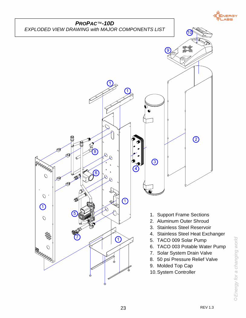
PROPAC™-10D EXPLODED VIEW DRAWING with MAJOR COMPONENTS LIST
1. Support Frame Sections
2. Aluminum Outer Shroud
3. Stainless Steel Reservoir
4. Stainless Steel Heat Exchanger
5. TACO 009 Solar Pump
6. TACO 003 Potable Water Pump
7. Solar System Drain Valve
8. 50 psi Pressure Relief Valve
9. Molded Top Cap
10. System Controller

REV 1.3 24
This system has been installed and will be serviced by:
Call this Company for repairs.
The systems and components in this manual are manufactured and supplied by:
ENERGY LABORATORIES, INC. 5191 Shawland Road Jacksonville, FL 32254
6935 15th St E Ste 120 • Sarasota, FL 34243Phone 941 360 9276 • Fax 941 359 [email protected] • [email protected] solardirect.com