results from the pmt test bench in bcn (10-oct-03)
DESCRIPTION
Results from the PMT test bench in BCN (10-Oct-03). J.Garra, R.Graciani, E.Graugés, X.Xirgu. 8 stage PMT. CFD base: The output of 1 channel studied to perform a premilinary analysis on: Signal Shape Gain Number of photo-electrons. CFD active base. Signal Shape. - PowerPoint PPT PresentationTRANSCRIPT

Results from the PMT test bench in BCN (10-Oct-03)
J.Garra, R.Graciani, E.Graugés, X.Xirgu

8 stage PMT
CFD base: The output of 1 channel studied to
perform a premilinary analysis on: Signal Shape Gain Number of photo-electrons

CFD active base

Signal Shape
4600 4800 5000 5200 5400 5600 5800 6000 6200 6400
-0.040
-0.035
-0.030
-0.025
-0.020
-0.015
-0.010
-0.005
0.000
0.005
Sig
na
l
Units of time (aprox. 0.1 ns)
Signal taken with a recycled setup
Some oscillations in the signal shape are supposed to be caused by some connection(?) problem.

Gain vs Photo-Statistics
0 20 40 60 80 100 120 140460000
480000
500000
520000
540000
560000
580000
600000
620000
Ga
in
Number of photoelectrons
Dependence gain-number of photoelectrons
• Possible saturation effects might be observed starting around 50 phe and above

Gain
650 700 750 800 850 900
100000
1000000
2 = 500090665.89604
R2 = 0.99727 A = 1.3094E-15 ± 1.4236E-15B = 7.11223 ± 0.16104
Ga
in
-HV (V)
Dependence gain-source voltage
Our desired HV working point should be ~ 600 Volts obtaining an approximate gain of 30k to 50k

8 stage PMT BCN base:
A preliminary study has been performed with a LED source (no fibre)
Gain and Photo-statistics have been looked at from the output of a 1 channel (#64)
Now the setup is ready to get measurements for all the channels at once.
Fatal accident ended up with the 8-stage PMT becoming unusable anymore
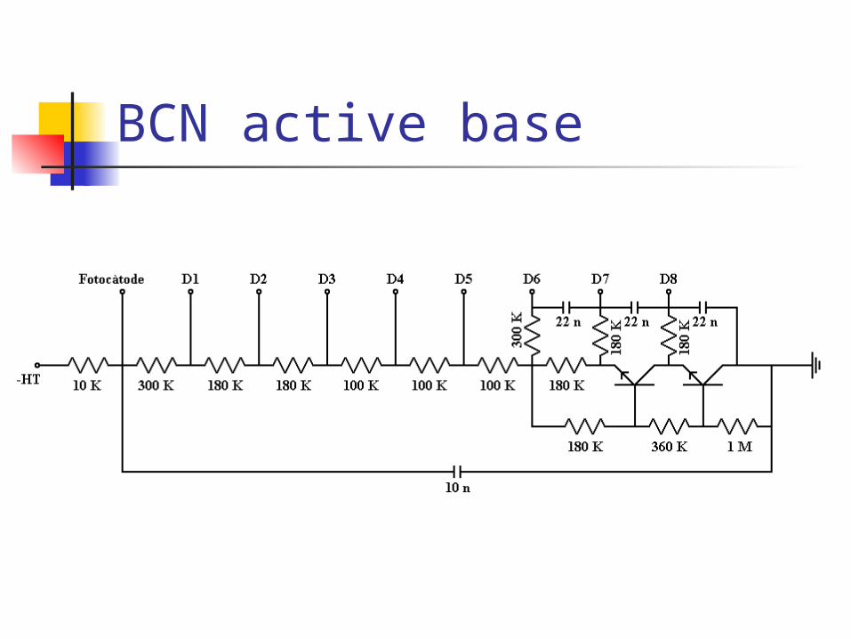
BCN active base
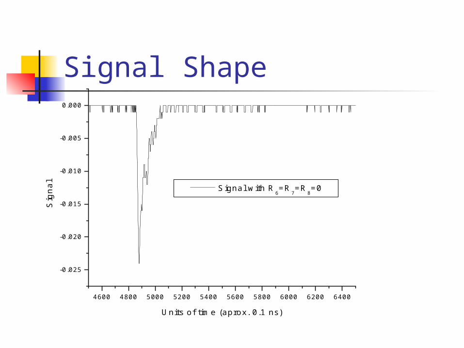
Signal Shape
4600 4800 5000 5200 5400 5600 5800 6000 6200 6400
-0.025
-0.020
-0.015
-0.010
-0.005
0.000
Sig
na
l
Units of time (aprox. 0.1 ns)
Signal with R6=R
7=R
8=0

4600 4800 5000 5200 5400 5600 5800 6000 6200 6400-0.05
-0.04
-0.03
-0.02
-0.01
0.00
Sig
nal
Units of time (aprox. 0.1 ns)
Signal with R6=310 K, R
7=R
8=180 K
Signal Shape

The oscillations present in the first attempt (CFD) could be partially removed (with the BCN base) by when the setup has been re-done very carefully and assuring a common grounding for the (ADC/Black Box/Active Base) system.
Still to be tried if that also cured the oscillation observed using the CFD base

12 stage PMT This PMT has already incorporated the
active base by Hamamatsu together with the (PMT/Base) system encapsulation
Scans of 50x50 measurements each have been performed for different angles to ensure the geometrical consistency of the setup (PMT plane parallel to the fiber scaning plane): 0,90,180 and 360 deg. scans
Also scans with different light intensities have been taken to test the uniformity in the linear response of each channel.

2D Scans
Different angles
Different light I
Documento Acrobat
Documento Acrobat

To do list
Let the new team get more experienced
Complete a final version of the fine scans (Motor lost steps, etc…).
Understand any the level of saturation of the signal
Single photo-electron measurement using a 2-stage amplifier board (work in progress)