resistors - learn.sparkfun - resistors - sparkfun electronics · pdf filedifferent variations...
TRANSCRIPT
Resistors a learn.sparkfun.com tutorial
Available online at: http://sfe.io/t64
Contents
Take a Stance, The Resist StanceResistor BasicsTypes of ResistorsDecoding Resistor MarkingsPower RatingSeries and Parallel ResistorsExample ApplicationsPurchasing ResistorsResources and Going Further
Take a Stance, The Resist Stance
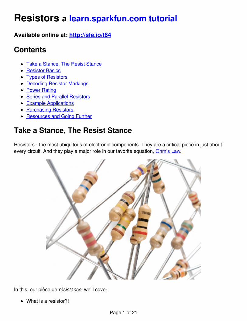
Resistors - the most ubiquitous of electronic components. They are a critical piece in just aboutevery circuit. And they play a major role in our favorite equation, Ohm’s Law.
In this, our pièce de résistance, we’ll cover:
What is a resistor?!
Page 1 of 21
Resistor unitsResistor circuit symbol(s)Resistors in series and parallelDifferent variations of resistorsColor coding decodingSurface mount resistor decodingExample resistor applications
Consider reading…
Some of the concepts in this tutorial build on previous electronics knowledge. Before jumping intothis tutorial, consider reading (at least skimming) these first:
What is Electricity?Voltage, Current, Resistance, and Ohm’s LawWhat is a CircuitSeries vs. Parallel CircuitsHow to Use A Multimeter - Specifically check out the measuring resistance section.Metric Prefixes
Resistor Basics
Resistors are electronic components which have a specific, never-changing electrical resistance.The resistor’s resistance limits the flow of electrons through a circuit.
They are passive components, meaning they only consume power (and can’t generate it).Resistors are usually added to circuits where they complement active components like op-amps,microcontrollers, and other integrated circuits. Commonly resistors are used to limit current, dividevoltages, and pull-up I/O lines.
Resistor units
The electrical resistance of a resistor is measured in ohms. The symbol for an ohm is the greekcapital-omega: Ω. The (somewhat roundabout) definition of 1Ω is the resistance between two pointswhere 1 volt (1V) of applied potential energy will push 1 ampere (1A) of current.
As SI units go, larger or smaller values of ohms can be matched with a prefix like kilo-, mega-, orgiga-, to make large values easier to read. It’s very common to see resistors in the kilohm (kΩ) andmegaohm (MΩ) range (much less common to see miliohm (mΩ) resistors). For example, a 4,700Ωresistor is equivalent to a 4.7kΩ resistor, and a 5,600,000Ω resistor can be written as 5,600kΩ or(more commonly as) 5.6MΩ.
Schematic symbol
Page 2 of 21

All resistors have two terminals, one connection on each end of the resistor. When modeled on aschematic, a resistor will show up as one of these two symbols:
Two common resistor schematic symbols. R1 is an American-style 1kΩ resistor, and R2 is aninternational-style 47kΩ resistor.
The terminals of the resistor are each of the lines extending from the squiggle (or rectangle). Thoseare what connect to the rest of the circuit.
The resistor circuit symbols are usually enhanced with both a resistance value and a name. Thevalue, displayed in ohms, is obviously critical for both evaluating and actually constructing thecircuit. The name of the resistor is usually an R preceding a number. Each resistor in a circuitshould have a unique name/number. For example, here’s a few resistors in action on a 555 timercircuit:
In this circuit, resistors play a key role in setting the frequency of the 555 timer’s output. Anotherresistor (R3) limits the current through an LED.
Page 3 of 21

Types of Resistors
Resistors come in a variety of shapes and sizes. They might be through-hole or surface-mount.They might be a standard, static resistor, a pack of resistors, or a special variable resistor.
Termination and mounting
Resistors will come in one of two termination-types: through-hole or surface-mount. These types ofresistors are usually abbreviated as either PTH (plated through-hole) or SMD/SMT (surface-mounttechnology or device).
Through-hole resistors come with long, pliable leads which can be stuck into a breadboard orhand-soldered into a prototyping board or printed circuit board (PCB). These resistors are usuallymore useful in breadboarding, prototyping, or in any case where you’d rather not solder tiny, little0.6mm-long SMD resistors. The long leads usually require trimming, and these resistors are boundto take up much more space than their surface-mount counterparts.
The most common through-hole resistors come in an axial package. The size of an axial resistor isrelative to its power rating. A common ½W resistor measures about 9.2mm across, while a smaller¼W resistor is about 6.3mm long.
A half-watt (½W) resistor (above) sized up to a quarter-watt (¼W).
Surface-mount resistors are usually tiny black rectangles, terminated on either side with evensmaller, shiny, silver, conductive edges. These resistors are intended to sit on top of PCBs, wherethey’re soldered onto mating landing pads. Because these resistors are so small, they’re usually setinto place by a robot, and sent through an oven where solder melts and holds them in place.
Page 4 of 21

A tiny 0603 330Ω resistor hovering over shiny George Washington’s nose on top of a U.S. quarter.
SMD resistors come in standardized sizes; usually either 0805 (0.8mm long by 0.5mm wide), 0603,or 0402. They’re great for mass circuit-board-production, or in designs where space is a preciouscommodity. They take a steady, precise hand to manually solder, though!
Resistor composition
Resistors can be constructed out of a variety of materials. Most common, modern resistors aremade out of either a carbon, metal, or metal-oxide film. In these resistors, a thin film ofconductive (though still resistive) material is wrapped in a helix around and covered by an insulatingmaterial. Most of the standard, no-frills, through-hole resistors will come in a carbon-film or metal-film composition.
Peek inside the guts of a few carbon-film resistors. Resistance values from top to bottom: 27Ω,330Ω and a 3.3MΩ. Inside the resistor, a carbon film is wrapped around an insulator. More wraps
Page 5 of 21

means a higher resistance. Pretty neat!
Other through-hole resistors might be wirewound or made of super-thin metallic foil. These resistorsare usually more expensive, higher-end components specifically chosen for their uniquecharacteristics like a higher power-rating, or maximum temperature range.
Surface-mount resistors are usually either thick or thin-film variety. Thick-film is usually cheaperbut less precise than thin. In both resistor types, a small film of resistive metal alloy is sandwichedbetween a ceramic base and glass/epoxy coating, and then connected to the terminating conductiveedges.
Special resistor packages
There are a variety of other, special-purpose resistors out there. Resistors may come in pre-wiredpacks of five-or-so resistor arrays. Resistors in these arrays may share a common pin, or be set upas voltage dividers.
An array of five 330Ω resistors, all tied together at one end.
Resistors don’t have to be static either. Variable resistors, known as rheostats, are resistors whichcan be adjusted between a specific range of values. Similar to the rheostat is the potentiometer.Pots connect two resistors internally, in series, and adjust a center tap between them creating anadjustable voltage divider. These variable resistors are often used for inputs, like volume knobs,which need to be adjustable.
Page 6 of 21
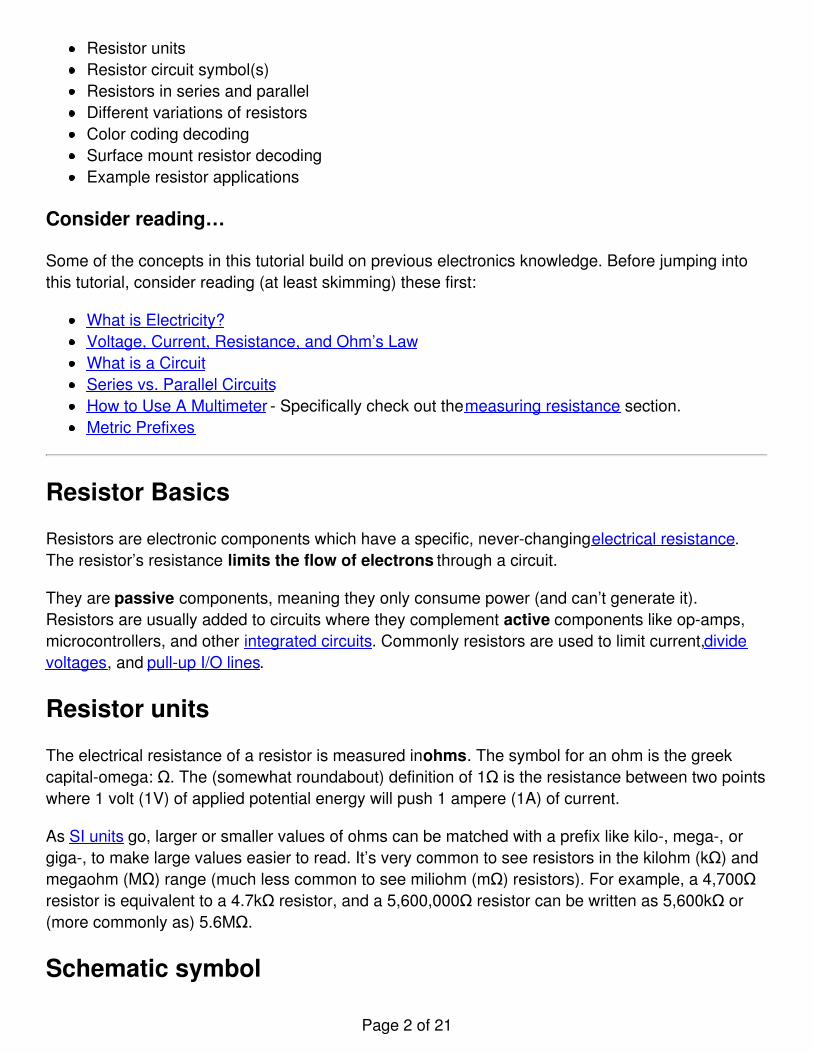
A smattering of potentiometers. From top-left, clockwise: a standard 10k trimpot, 2-axis joystick,softpot, slide pot, classic right-angle, and a breadboard friendly 10k trimpot.
Decoding Resistor Markings
Though they may not display their value outright, most resistors are marked to show what theirresistance is. PTH resistors use a color-coding system (which really adds some flair to circuits), andSMD resistors have their own value-marking system.
Decoding the color bands
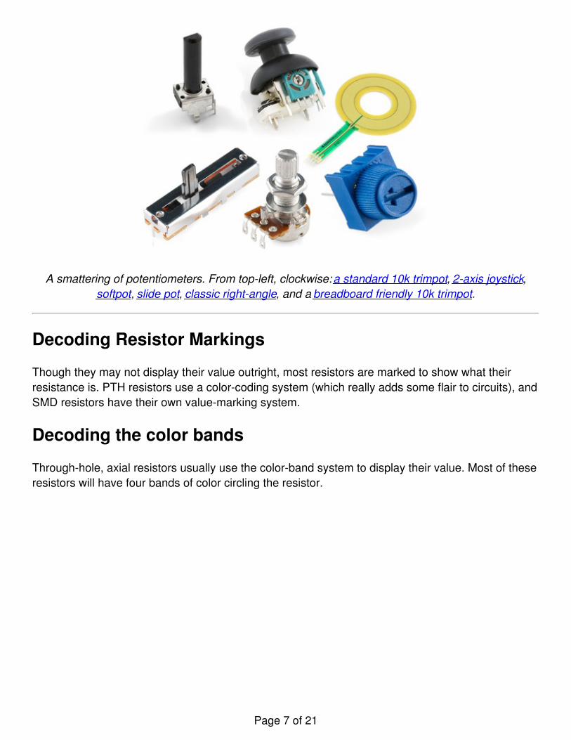
Through-hole, axial resistors usually use the color-band system to display their value. Most of theseresistors will have four bands of color circling the resistor.
Page 7 of 21

The first two bands indicate the two most-significant digits of the resistor’s value. The third bandis a weight value, which multiplies the two significant digits by a power of ten.
The final band indicates the tolerance of the resistor. The tolerance explains how much more orless the actual resistance of the resistor can be compared to what its nominal value is. No resistor ismade to perfection, and different manufacturing processes will result in better or worse tolerances.For example, a 1kΩ resistor with 5% tolerance could actually be anywhere between 0.95kΩ and1.05kΩ.
How do you tell which band is first and last? The last, tolerance band is often clearly separated fromthe value bands, and usually it’ll either be silver or gold.
Here’s a table of each of the colors and which value, multiplier or tolerance they represent:
ColorDigitvalue
Multiplier Multiplied Out Tolerance
Black 0 100 1
Brown 1 101 10
Red 2 102 100
Page 8 of 21

Orange 3 103 1,000
Yellow 4 104 10000
Green 5 105 100,000
Blue 6 106 1,000,000
Violet 7 107 10,000,000
Gray 8 108 100,000,000
White 9 109 1,000,000,000
Gold ±5%
Silver ±10%
Here’s an example of a 4.7kΩ resistor with four color bands:
When decoding the resistor color bands, consult a resistor color code table like the one above. Forthe first two bands, find that color’s corresponding digit value. The 4.7kΩ resistor has color bands ofyellow and violet to begin - which have digit values of 4 and 7 (47). The third band of the 4.7kΩ isred, which indicates that the 47 should be multiplied by 102 (or 100). 47 times 100 is 4,700!
If you’re trying to commit the color band code to memory, a mnemonic device might help. There area handful of (sometimes unsavory) mnemonics out there, to help remember the resistor color code.A good one, which spells out the difference between black and brown is:
"Big brown rabbits often yield great big vocal groans when gingerly snapped."
Or, if you remember “ROY G. BIV”, subtract the indigo (poor indigo, no one remembers indigo), andadd black and brown to the front and gray and white to the back of the classic rainbow color-order.
Page 9 of 21
Color Code Calculator
If you’d rather skip the math (we won’t judge :), and just use a handy calculator, give this a try!
Band 1 Band 2 Band 3 Band 4
Value 1 (MSV) Value 2 Weight Tolerance
Brown (1) Black (0) Red (100) Gold (± 5%)
Resistance: 1,000 Ω ±5%
Decoding surface-mount markings
SMD resistors, like those in 0603 or 0805 packages, have their own way of displaying their value.There are a few common marking methods you’ll see on these resistors. They’ll usually have threeto four characters – numbers or letters – printed on top of the case.
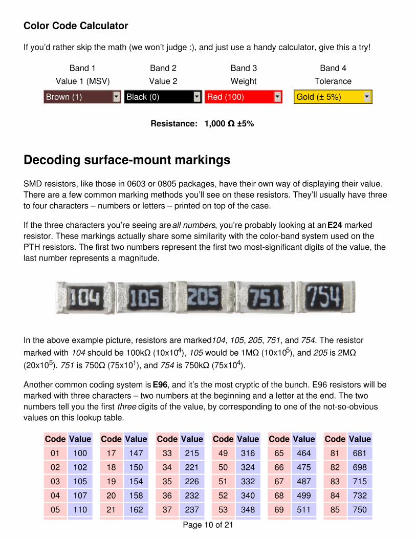
If the three characters you’re seeing are all numbers, you’re probably looking at an E24 markedresistor. These markings actually share some similarity with the color-band system used on thePTH resistors. The first two numbers represent the first two most-significant digits of the value, thelast number represents a magnitude.
In the above example picture, resistors are marked 104, 105, 205, 751, and 754. The resistormarked with 104 should be 100kΩ (10x104), 105 would be 1MΩ (10x105), and 205 is 2MΩ(20x105). 751 is 750Ω (75x101), and 754 is 750kΩ (75x104).
Another common coding system is E96, and it’s the most cryptic of the bunch. E96 resistors will bemarked with three characters – two numbers at the beginning and a letter at the end. The twonumbers tell you the first three digits of the value, by corresponding to one of the not-so-obviousvalues on this lookup table.
Code Value Code Value Code Value Code Value Code Value Code Value
01 100 17 147 33 215 49 316 65 464 81 681
02 102 18 150 34 221 50 324 66 475 82 698
03 105 19 154 35 226 51 332 67 487 83 715
04 107 20 158 36 232 52 340 68 499 84 732
05 110 21 162 37 237 53 348 69 511 85 750
Page 10 of 21
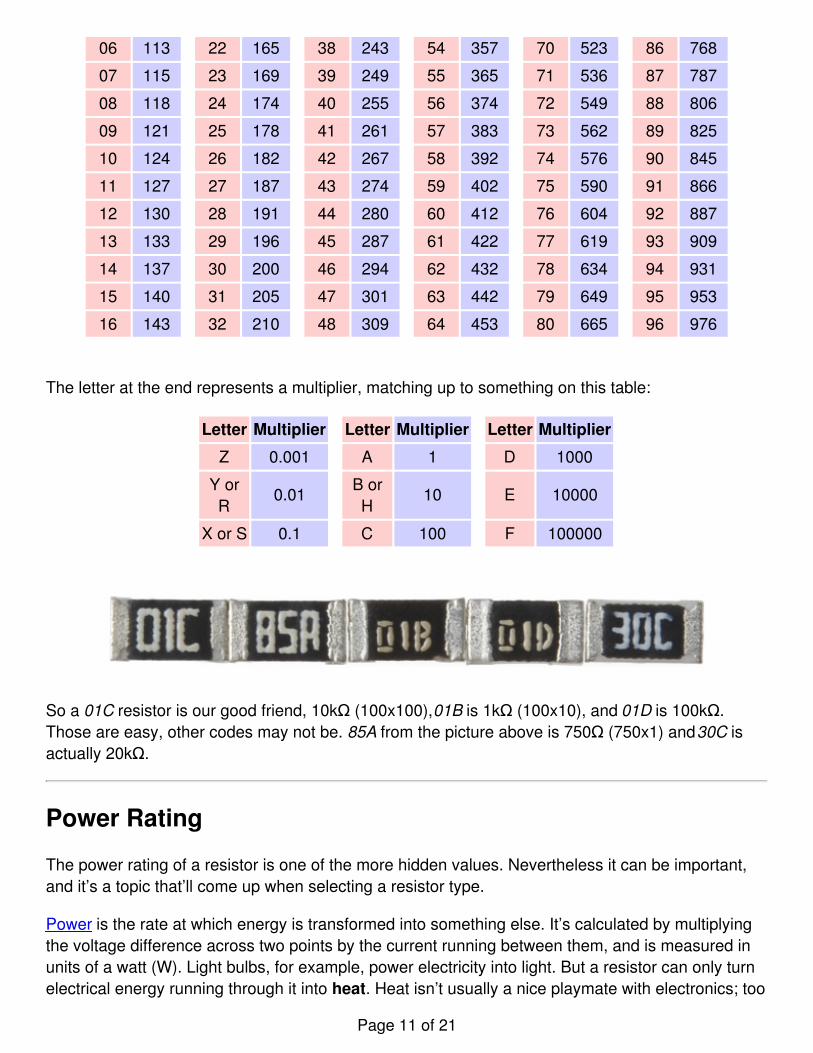
06 113 22 165 38 243 54 357 70 523 86 768
07 115 23 169 39 249 55 365 71 536 87 787
08 118 24 174 40 255 56 374 72 549 88 806
09 121 25 178 41 261 57 383 73 562 89 825
10 124 26 182 42 267 58 392 74 576 90 845
11 127 27 187 43 274 59 402 75 590 91 866
12 130 28 191 44 280 60 412 76 604 92 887
13 133 29 196 45 287 61 422 77 619 93 909
14 137 30 200 46 294 62 432 78 634 94 931
15 140 31 205 47 301 63 442 79 649 95 953
16 143 32 210 48 309 64 453 80 665 96 976
The letter at the end represents a multiplier, matching up to something on this table:
Letter Multiplier Letter Multiplier Letter Multiplier
Z 0.001 A 1 D 1000
Y orR
0.01B orH
10 E 10000
X or S 0.1 C 100 F 100000
So a 01C resistor is our good friend, 10kΩ (100x100), 01B is 1kΩ (100x10), and 01D is 100kΩ.Those are easy, other codes may not be. 85A from the picture above is 750Ω (750x1) and 30C isactually 20kΩ.
Power Rating
The power rating of a resistor is one of the more hidden values. Nevertheless it can be important,and it’s a topic that’ll come up when selecting a resistor type.
Power is the rate at which energy is transformed into something else. It’s calculated by multiplyingthe voltage difference across two points by the current running between them, and is measured inunits of a watt (W). Light bulbs, for example, power electricity into light. But a resistor can only turnelectrical energy running through it into heat. Heat isn’t usually a nice playmate with electronics; too
Page 11 of 21
much heat leads to smoke, sparks, and fire!
Every resistor has a specific maximum power rating. In order to keep the resistor from heating uptoo much, it’s important to make sure the power across a resistor is kept under it’s maximum rating.The power rating of a resistor is measured in watts, and it’s usually somewhere between ⅛W(0.125W) and 1W. Resistors with power ratings of more than 1W are usually referred to as powerresistors, and are used specifically for their power dissipating abilities.
Finding a resistor’s power rating
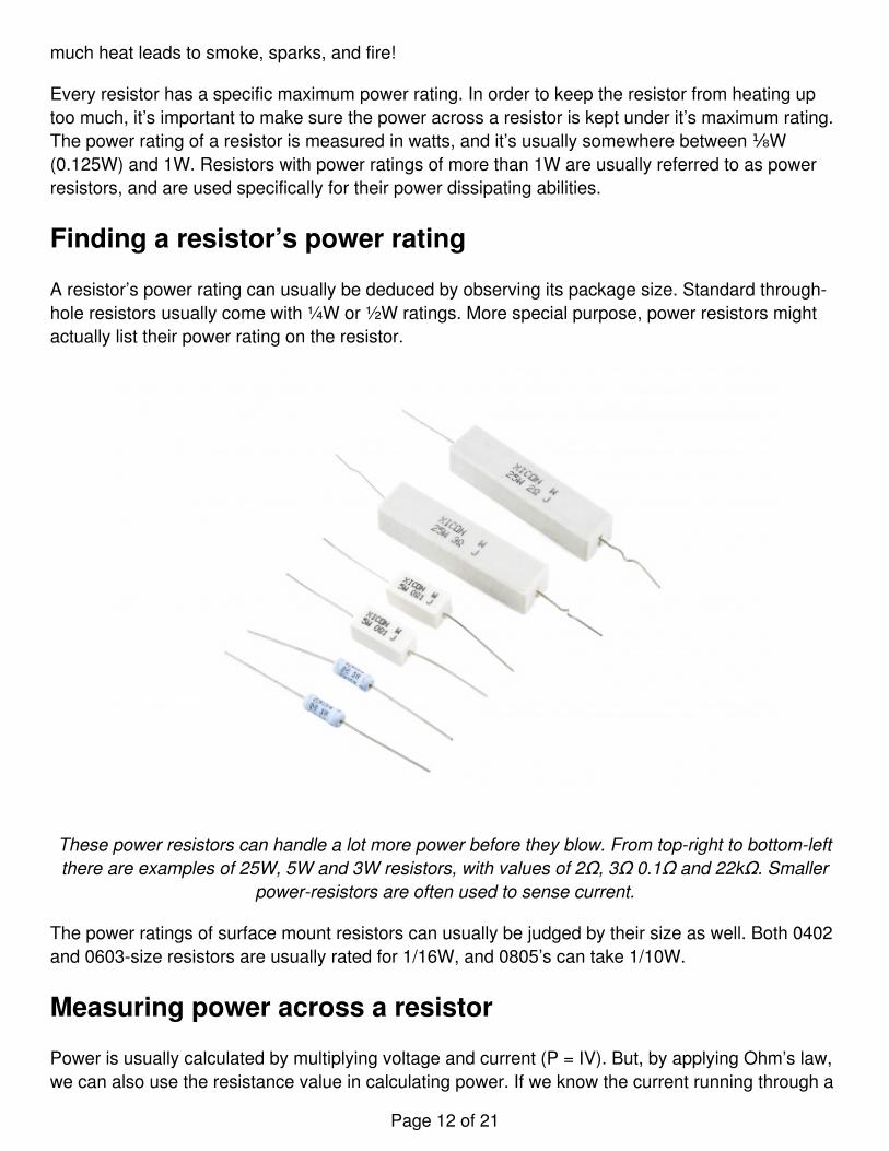
A resistor’s power rating can usually be deduced by observing its package size. Standard through-hole resistors usually come with ¼W or ½W ratings. More special purpose, power resistors mightactually list their power rating on the resistor.
These power resistors can handle a lot more power before they blow. From top-right to bottom-leftthere are examples of 25W, 5W and 3W resistors, with values of 2Ω, 3Ω 0.1Ω and 22kΩ. Smaller
power-resistors are often used to sense current.
The power ratings of surface mount resistors can usually be judged by their size as well. Both 0402and 0603-size resistors are usually rated for 1/16W, and 0805’s can take 1/10W.
Measuring power across a resistor
Power is usually calculated by multiplying voltage and current (P = IV). But, by applying Ohm’s law,we can also use the resistance value in calculating power. If we know the current running through a
Page 12 of 21

resistor, we can calculate the power as:
Or, if we know the voltage across a resistor, the power can be calculated as:
Series and Parallel Resistors
Resistors are paired together all the time in electronics, usually in either a series or parallel circuit.When resistors are combined in series or parallel, they create a total resistance, which can becalculated using one of two equations. Knowing how resistor values combine comes in handy if youneed to create a specific resistor value.
Series resistors
When connected in series resistor values simply add up.
N resistors in series. The total resistance is the sum of all series resistors.
So, for example, if you just have to have a 12.33kΩ resistor, seek out some of the more commonresistor values of 12kΩ and 330Ω, and butt them up together in series.
Parallel resistors
Finding the resistance of resistors in parallel isn’t quite so easy. The total resistance of N resistorsin parallel is the inverse of the sum of all inverse resistances. This equation might make moresense than that last sentence:
Page 13 of 21
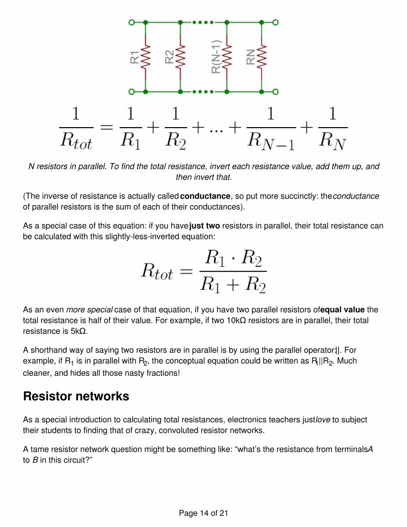
N resistors in parallel. To find the total resistance, invert each resistance value, add them up, andthen invert that.
(The inverse of resistance is actually called conductance, so put more succinctly: the conductanceof parallel resistors is the sum of each of their conductances).
As a special case of this equation: if you have just two resistors in parallel, their total resistance canbe calculated with this slightly-less-inverted equation:
As an even more special case of that equation, if you have two parallel resistors of equal value thetotal resistance is half of their value. For example, if two 10kΩ resistors are in parallel, their totalresistance is 5kΩ.
A shorthand way of saying two resistors are in parallel is by using the parallel operator: ||. Forexample, if R1 is in parallel with R2, the conceptual equation could be written as R1||R2. Muchcleaner, and hides all those nasty fractions!
Resistor networks
As a special introduction to calculating total resistances, electronics teachers just love to subjecttheir students to finding that of crazy, convoluted resistor networks.
A tame resistor network question might be something like: “what’s the resistance from terminals Ato B in this circuit?”
Page 14 of 21

To solve such a problem, start at the back-end of the circuit and simplify towards the two terminals.In this case R7, R8 and R9 are all in series and can be added together. Those three resistors are inparallel with R6, so those four resistors could be turned into one with a resistance of R6||(R7+R8+R9). Making our circuit:
Now the four right-most resistors can be simplified even further. R4, R5 and our conglomeration ofR6 - R9 are all in series and can be added. Then those series resistors are all in parallel with R3.
And that’s just three series resistors between the A and B terminals. Add ‘em on up! So the total
Page 15 of 21

resistance of that circuit is: R1+R2+R3||(R4+R5+R6||(R7+R8+R9)).
Example Applications
Resistors exist in just about every electronic circuit ever. Here are a few examples of circuits, whichheavily depend on our resistor friends.
LED Current Limiting
Resistors are key in making sure LEDs don’t blow up when power is applied. By connecting aresistor in series with an LED, current flowing through the two components can be limited to a safevalue.
When sizing out a current-limiting resistor, look for two characteristic values of the LED: the typicalforward voltage, and the maximum forward current. The typical forward voltage is the voltagewhich is required to make an LED light up, and it varies (usually somewhere between 1.7V and3.4V) depending upon the color of the LED. The maximum forward current is usually around 20mAfor basic LEDs; continuous current through the LED should always be equal to or less than thatcurrent rating.
Once you’ve gotten ahold of those two values, you can size up a current-limiting resistor with thisequation:
Page 16 of 21

VS is the source voltage – usually a battery or power supply voltage. VF and IF are the LED’sforward voltage and the desired current that runs through it.
For example, assume you have a 9V battery to power an LED. If your LED is red, it might have aforward voltage around 1.8V. If you want to limit the current to 10mA, use a series resistor of about720Ω.
Voltage Dividers
A voltage divider is a resistor circuit which turns a large voltage into a smaller one. Using just tworesistors in series, an output voltage can be created that’s a fraction of the input voltage.
Here’s the voltage divider circuit:
Two resistors, R1 and R2, are connected in series and a voltage source (Vin) is connected across
Page 17 of 21

them. The voltage from Vout to GND can be calculated as:
For example, if R1 was 1.7kΩ and R2 was 3.3kΩ, a 5V input voltage could be turned into 3.3V at theVout terminal.
Voltage dividers are very handy for reading resistive sensors, like photocells, flex sensors, andforce-sensitive resistors. One half of the voltage divider is the sensor, and the part is a staticresistor. The output voltage between the two components is connected to an analog-to-digitalconverter on a microcontroller (MCU) to read the sensor’s value.
Here a resistor R1 and a photocell create a voltage divider to create a variable voltage output.
Pull-up Resistors
A pull-up resistor is used when you need to bias a microcontroller’s input pin to a known state. Oneend of the resistor is connected to the MCU’s pin, and the other end is connected to a high voltage(usually 5V or 3.3V).
Without a pull-up resistor, inputs on the MCU could be left floating. There’s no guarantee that afloating pin is either high (5V) or low (0V).
Page 18 of 21

Pull-up resistors are often used when interfacing with a button or switch input. The pull-up resistorcan bias the input-pin when the switch is open. And it will protect the circuit from a short when theswitch is closed.
In the circuit above, when the switch is open the MCU’s input pin is connected through the resistorto 5V. When the switch closes, the input pin is connected directly to GND.
The value of a pull-up resistor doesn’t usually need to be anything specific. But it should be highenough that not too much power is lost if 5V or so is applied across it. Usually values around 10kΩwork well.
Purchasing Resistors
Don’t limit your flow of resistors. We’ve got kits, packs, and single pieces that you just can’t resist.
Our recommendations:
Resistor Kit - 1/4W (500 total)
COM-10969$7.95142
Page 19 of 21

Favorited Favorite 113Wish List
Resistor 10K Ohm 1/6th Watt PTH - 20 pack
COM-11508$0.95Favorited Favorite 4Wish List
Resistor 330 Ohm 1/6 Watt PTH - 20 pack
COM-11507$0.952Favorited Favorite 11Wish List
Power Resistor Kit - 10W (25 pack)
KIT-13053$5.95
Page 20 of 21

2Favorited Favorite 9Wish List
Resources and Going Further
Now that you’re a budding expert on all things resistor, how ‘bout exploring some more fundamentalelectronics concepts! Resistors certainly aren’t the only basic component we use in electronics,there’s also:
CapacitorsDiodesTransistorsIntegrated Circuits (ICs)
Or maybe you’d like to further explore resistor applications?
Voltage DividersPull-up Resistors
learn.sparkfun.com | CC BY-SA 3.0 | SparkFun Electronics | Niwot, Colorado
Page 21 of 21