residentialstructuraldesignguide: : 2000 edition - … · ·...
TRANSCRIPT

U.S. Department of Housing and Urban Development Office of Policy Development and Research
RReessiiddeennttiiaall SSttrruuccttuurraall DDeessiiggnn GGuuiiddee:: 2000 Edition
AA SSttaattee--ooff--tthhee--AArrtt RReevviieeww aanndd AApppplliiccaattiioonn ooff EEnnggiinneeeerriinngg IInnffoorrmmaattiioonn ffoorr LLiigghhtt--FFrraammee HHoommeess,,
AAppaarrttmmeennttss,, aanndd TToowwnnhhoouusseess

PATH (Partnership for Advanced Technology in Housing) is a new private/public effort to develop, demonstrate,and gain widespread market acceptance for the “Next Generation” of American housing. Through the use of new orinnovative technologies the goal of PATH is to improve the quality, durability, environmental efficiency, andaffordability of tomorrow’s homes.
Initiated at the request of the White House, PATH is managed and supported by the Department of Housing andUrban Development (HUD). In addition, all Federal Agencies that engage in housing research and technologydevelopment are PATH Partners, including the Departments of Energy and Commerce, as well as the EnvironmentalProtection Agency (EPA) and the Federal Emergency Management Agency (FEMA). State and local governmentsand other participants from the public sector are also partners in PATH. Product manufacturers, home builders,insurance companies, and lenders represent private industry in the PATH Partnership.
To learn more about PATH, please contact:
Suite B133451 7th Street, SWWashington, DC 20410202-708-4250 (fax)e-mail: [email protected]: www.pathnet.org

Residential Structural Design Guide:
A State-of-the-Art Review and Appllication ofEngineering Information for Light-Frame Homes,
Apartments, and Townhouses
Residential Structural Design Guide:2000 Edition
A State-of-the-Art Review and App ication of Engineering Information for Light-Frame Homes,
Apartments, and Townhouses
Prepared for
U.S. Department of Housing and Urban Development Office of Policy Development and Research
Washington, DC
Contract H-21065CA
and
National Association of Home Builders Housing Affordability Through Design Efficiency Program
Washington, DC
byNAHB Research Center, Inc.Upper Marlboro, Maryland
February 2000

AcknowledgmentsThis document was prepared by the NAHB Research Center, Inc. The work was
sponsored by the U.S. Department of Housing and Urban Development (HUD) and cofunded by the National Association of Home Builders (NAHB). The principal authors of the guide are Jay Crandell, P.E., and Andrea Vrankar, P.E., R.A., with contributions from Donald F. Luebs. Graphics were produced by Barbara Vrankar Karim, Lisa Zimmerman, and Mary Ellen Howard. Special appreciation is extended to William Freeborne and Riley Chung of HUD for their review and guidance throughout the project. Appreciation is also extended to the following individuals whose comments made this work more complete: Patrick Bridges, Bridges and Associates; Dr. Eric F.P. Burnett, Pennsylvania Housing Research Center; Kirk Grundahl, Wood Truss Council of America; David Mason, Southern Forest Products Association; and Mark Nowak, NAHB Research Center, Inc. A special thank you is extended to David Gromala, Brad Douglas, David Rosowsky, Thomas Williamson, and Michael Baker for their instructive criticism and technical suggestions that significantly improved the soundness of this work. The significant editorial contributions of Carol Soble are certainly recognized for the improved quality of this writing. Finally, for the hours of hard work and rework in pulling this document together, the authors extend many thanks to Lynda Marchman.
ABOUT THE NAHB RESEARCH CENTER, INC.
The NAHB Research Center is a not-for-profit subsidiary of the National Association of Home Builders (NAHB). The NAHB has 190,000 members, including 50,000 builders who build more than 80 percent of new American homes. NAHB Research Center conducts research, analysis, and demonstration programs in all areas relating to home building and carries out extensive programs of information dissemination and interchange among members of the industry and between the industry and the public.
NOTICE
The contents of this report are the views of the contractor and do not necessarily reflect the views or policies of the U.S. Department of Housing and Urban Development or the U.S. government.
While the information in this document is believed to be accurate, neither the authors, nor reviewers, nor the U.S. Department of Housing and Urban Development, nor the NAHB Research Center, Inc., nor any of their employees or representatives makes any warranty, guarantee, or representation, expressed or implied, with respect to the accuracy, effectiveness, or usefulness of any information, method, or material in this document, nor assumes any liability for the use of any information, methods, or materials disclosed herein, or for damages arising from such use. This publication is intended for the use of professional personnel who are competent to evaluate the significance and limitations of the reported information and who will accept responsibility for the application of the material it contains. All responsibility as to the appropriate use of information in this document is the responsibility of the reader or user.
The U.S. government does not endorse products or manufacturers. Trade or manufacturer’s names that appear herein are used solely because they are considered essential to the objective of this report.
ii Residential Structural Design Guide
Foreword
The increasing complexity of homes, the use of innovative materials and technologies, and the increased population in high-hazard areas of the United States have introduced many challenges to the building industry and design profession as a whole. These challenges call for the development and continual improvement of efficient engineering methods for housing applications as well as for the education of designers in the uniqueness of housing as a structural design problem.
This text is an initial effort to document and improve the unique structural engineering knowledge related to housing design and performance. It compliments current design practices and building code requirements with value-added technical information and guidance. In doing so, it supplements fundamental engineering principles with various technical resources and insights that focus on improving the understanding of conventional and engineered housing construction. Thus, it attempts to address deficiencies and inefficiencies in past housing construction practices and structural engineering concepts through a comprehensive design approach that draws on existing and innovative engineering technologies in a practical manner. The guide may be viewed as a “living document” subject to further improvement as the art and science of housing design evolves.
We hope that this guide will facilitate and advance efficient design of future housing whether built in conformance with prescriptive (i.e., “conventional”) practices or specially engineered in part or whole. The desired effect is to continue to improve the value of American housing in terms of economy and structural performance.
Susan M. Wachter Assistant Secretary for Policy
Development and Research

Preface
This document is a unique and comprehensive tool for design professionals, particularly structural engineers, seeking to provide value-added services to the producers and consumers of American housing. As such, the guide is organized around the following major objectives:
• to present a sound perspective on American housing relative to its history, construction characteristics, regulation, and performance experience;
• to provide the latest technical knowledge and engineering approaches for the design of homes to complement current code-prescribed design methods;
• to assemble relevant design data and methods in a single, comprehensive format that is instructional and simple to apply for the complete design of a home; and
• to reveal areas where gaps in existing research, design specifications, and analytic tools necessitate alternative methods of design and sound engineering judgment to produce efficient designs.
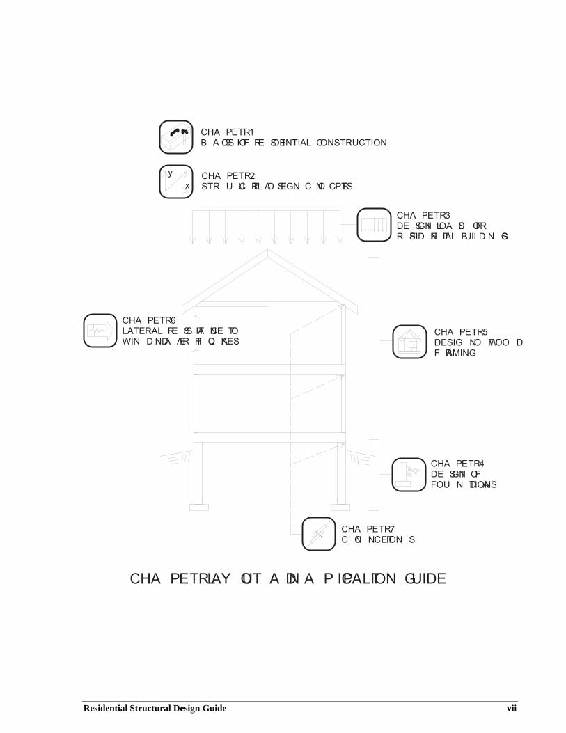
This guide consists of seven chapters. The layout and application of the various chapters are illustrated in the figure on page vii. Chapter 1 describes the basic substance of American housing, including conventional construction practices, alternative materials, building codes and standards, the role of design professionals, and actual experience with respect to performance problems and successes, particularly as related to natural hazards such as hurricanes and earthquakes. Chapter 2 introduces basic engineering concepts regarding safety, load path, and the structural system response of residential buildings, subassemblies, and components to various types of loads. Chapter 3 addresses design loads applicable to residential construction. Chapters 4 and 5 provide step-by-step design procedures for the various components and assemblies comprising the structure of a home—from the foundation to the roof. Chapter 6 is devoted to the design of light-frame homes to resist lateral loads from wind and earthquakes. Chapter 7 addresses the design of various types of connections in a wood-framed home that are important to the overall function of the numerous component parts. As appropriate, the guide offers additional resources and references on the topics addressed.
Given that most homes in the United States are built with wood structural materials, the guide focuses on appropriate methods of design associated with wood for the above-grade portion of the structure. Concrete or masonry are generally assumed to be used for the below-grade portion of the structure, although preservative-treated wood may also be used. Other materials and systems using various innovative approaches are considered in abbreviated form as appropriate. In some cases, innovative materials or systems can be used to address specific issues in the design and performance of homes. For example, steel framing is popular in Hawaii partly because of wood’s special
Residential Structural Design Guide v
problems with decay and termite damage. Likewise, partially reinforced masonry construction is used extensively in Florida because of its demonstrated ability to perform in high winds.
For typical wood-framed homes, the primary markets for engineering services lie in special load conditions, such as girder design for a custom house; corrective measures, such as repair of a damaged roof truss or floor joist; and high-hazard conditions such as on the West Coast (earthquakes) and the Gulf and Atlantic coasts (hurricanes). The design recommendations in the guide are based on the best information available to the authors for the safe and efficient design of homes. Much of the technical information and guidance is supplemental to building codes, standards, and design specifications that define current engineering practice. In fact, current building codes may not explicitly recognize some of the technical information or design methods described or recommended in the guide. Therefore, a competent professional designer should first compare and understand any differences between the content of this guide and local building code requirements. Any actual use of this guide by a competent professional may require appropriate substantiation as an "alternative method of analysis." The guide and references provided herein should help furnish the necessary documentation.
The use of alternative means and methods of design should not be taken lightly or without first carefully considering the wide range of implications related to the applicable building code’s minimum requirements for structural design, the local process of accepting alternative designs, the acceptability of the proposed alternative design method or data, and exposure to liability when attempting something new or innovative, even when carried out correctly. It is not the intent of this guide to steer a designer unwittingly into non-compliance with current regulatory requirements for the practice of design as governed by local building codes. Instead, the intent is to provide technical insights into and approaches to home design that have not been compiled elsewhere but deserve recognition and consideration. The guide is also intended to be instructional in a manner relevant to the current state of the art of home design.
Finally, it is hoped that this guide will foster a better understanding among engineers, architects, building code officials, and home builders by clarifying the perception of homes as structural systems. As such, the guide should help structural designers perform their services more effectively and assist in integrating their skills with others who contribute to the production of safe and affordable homes in the United States.
vi Residential Structural Design Guide
y
x
C H A P T E R 1 B A S I C S O F R E S I D E N T I A L C O N S T R U C T I O N
C H A P T E R 2 S T R U C T U R A L D E S I G N C O N C E P T S
C H A P T E R 3 D E S I G N L O A D S F O RR E S I D E N T I A L B U I L D I N G S
C H A P T E R 5W
C H A P T E R 7 C O N N E C T I O N S
C H A P T E R 6 L A T E R A L R E S I S T A N C E T O I N D A N D E A R T H Q U A K E S D E S I G N O F W O O D
F R A M I N G
C H A P T E R 4 D E S I G N O F F O U N D A T I O N S
C H A P T E R L A Y O U T A N D A P P L I C A T I O N G U I D E
Residential Structural Design Guide vii

ContentsPage
Chapter 1 - Basics of Residential Construction
1.1 Conventional Residential Construction......................................................................1-11.2 Industrialized Housing ...............................................................................................1-61.3 Alternative Materials and Methods ............................................................................1-71.4 Building Codes and Standards .................................................................................1-111.5 Role of the Design Professional ...............................................................................1-141.6 Housing Structural Performance ..............................................................................1-151.7 Summary ..................................................................................................................1-241.8 References ................................................................................................................1-25
Chapter 2 - Structural Design Concepts
2.1 General .......................................................................................................................2-12.2 What is Structural Design?.........................................................................................2-12.3 Load Conditions and Structural System Response ....................................................2-22.4 Load Path....................................................................................................................2-62.5 Structural Safety.......................................................................................................2-142.6 References ................................................................................................................2-23
Chapter 3 - Design Loads for Residential Buildings
3.1 General .......................................................................................................................3-13.2 Load Combinations ....................................................................................................3-23.3 Dead Loads.................................................................................................................3-43.4 Live Loads..................................................................................................................3-63.5 Soil Lateral Loads ......................................................................................................3-83.6 Wind Loads ..............................................................................................................3-113.7 Snow Loads ..............................................................................................................3-203.8 Earthquake Loads.....................................................................................................3-223.9 Other Load Conditions .............................................................................................3-303.10 Design Examples......................................................................................................3-313.11 References ................................................................................................................3-38
y
x
Chapter 4 - Design of Foundations
4.1 General .......................................................................................................................4-1
Residential Structural Design Guide ix
4.2 Material Properties .....................................................................................................4-44.3 Soil Bearing Capacity and Footing Size ....................................................................4-84.4 Footings....................................................................................................................4-104.5 Foundation Walls .....................................................................................................4-194.6 Slabs on Grade .........................................................................................................4-494.7 Pile Foundations.......................................................................................................4-504.8 Frost Protection ........................................................................................................4-534.9 Design Examples......................................................................................................4-584.10 References ................................................................................................................4-88
Chapter 5 - Design of Wood Framing
5.1 General .......................................................................................................................5-15.2 Material Properties .....................................................................................................5-35.3 Structural Evaluation................................................................................................5-155.4 Floor Framing...........................................................................................................5-245.5 Wall Framing............................................................................................................5-325.6 Roofs ........................................................................................................................5-395.7 Design Examples......................................................................................................5-485.8 References ................................................................................................................5-81
Chapter 6 - Lateral Resistance to Wind and Earthquakes
6.1 General .......................................................................................................................6-16.2 Overview of Whole-Building Tests ...........................................................................6-36.3 LFRS Design Steps and Terminology........................................................................6-56.4 The Current LFRS Design Practice..........................................................................6-116.5 Design Guidelines ....................................................................................................6-196.6 Design Examples......................................................................................................6-416.7 References ................................................................................................................6-74
Chapter 7 - Connections
7.1 General .......................................................................................................................7-17.2 Types of Mechanical Fasteners ..................................................................................7-37.3 Wood Connection Design ........................................................................................7-117.4 Design of Concrete and Masonry Connections........................................................7-237.5 Design Examples......................................................................................................7-287.6 References ................................................................................................................7-50
Appendix A - Shear and Moment Diagrams and Beam Equations
Appendix B - Unit Conversions
x Residential Structural Design Guide
List of Figures Page
Chapter 1 - Basics of Residential Construction
Figure 1.1a: Post-and-Beam Construction (Historical) 1-2Figure 1.1b: Balloon-Frame Construction (Historical) 1-3Figure 1.1c: Modern Platform-Frame Construction 1-4Figure 1.2: Modern Platform-Framed House under Construction 1-5Figure 1.3: House Construction Using Engineered Wood Components 1-8Figure 1.4: House Construction Using Cold-Formed Steel Framing 1-9Figure 1.5: House Construction Using Insulating Concrete Forms 1-10Figure 1.6: House Construction Using Concrete Masonry 1-11Figure 1.7: Use of Model Building Codes in the United States 1-12Figure 1.8: Maximum Gust Wind Speeds Experienced in Hurricane Andrew 1-19
y
x Chapter 2 - Structural Design Concepts
Figure 2.1: Illustration of the Vertical Load Path for Gravity Loads 2-7Figure 2.2: Illustration of the Vertical Load Path for Wind Uplift 2-8Figure 2.3: Illustration of the Lateral Load Path 2-12Figure 2.4: Illustration of Building Deformation under Lateral Load 2-13Figure 2.5: Basic Concept of Safety in LRFD and ASD Considering
the Variability of Loads and Resistance 2-21
Chapter 3 - Design Loads for Residential Buildings
Figure 3.1: Triangular Pressure Distribution on a Basement Foundation WallFigure 3.2: Basic Design Wind Speed Map from ASCE 7-98 3-13Figure 3.3: Ground Snow Loads (ASCE 7-98) 3-21Figure 3.4: Seismic Map of Design Short-Period Spectral Response Acceleration (g)
(2 percent chance of exceedance in 50 years or 2,475-year return period) 3-23
Chapter 4 - Design of Foundations
Figure 4.1: Types of Foundations 4-3Figure 4.2: Critical Failure Planes in Continuous or Square Concrete Spread Footings 4-13Figure 4.3: Variables Defined for Shear Calculations in Plain Concrete Walls 4-22Figure 4.4: Variables Defined for Shear Calculations in Reinforced Concrete Walls 4-25Figure 4.5: Typical Interaction Diagrams for Plain and Reinforced Concrete Walls 4-29
Residential Structural Design Guide xi
3-9
Figure 4.6: Design Variables Defined for Lintel Bending and Shear 4-31Figure 4.7: Variables Defined for Shear Calculations in Reinforced Concrete
Masonry WallsFigure 4.8: Concrete Masonry Wall Lintel TypesFigure 4.9: Preservative-Treated Wood Foundation WallsFigure 4.10: Insulating Concrete Form Foundation WallsFigure 4.11: Basic Coastal Foundation ConstructionFigure 4.12: Air-Freezing Index Map (100-Year Return Period)Figure 4.13: Frost-Protected Shallow Foundation Applications
Chapter 5 - Design of Wood Framing
4-41 4-44 4-46 4-48 4-51 4-55 4-56
Figure 5.1: Components and Assemblies of a Conventional Wood-Framed Home 5-2Figure 5.2: Structural Elements of the Floor System 5-25Figure 5.3: Conventional and Alternative Floor Framing Members 5-27Figure 5.4: Examples of Beams and Girders 5-29Figure 5.5: Structural Elements of the Wall System 5-33Figure 5.6: Wood Column Types 5-39Figure 5.7: Structural Elements of a Conventional Roof System 5-40Figure 5.8: Design Methods and Assumptions for a Sloped Roof Rafter 5-43Figure 5.9: Typical Roof Overhang Construction 5-47
Chapter 6 - Lateral Resistance to Wind and Earthquakes
Figure 6.1: Chords in Shear Walls and Horizontal Diaphragms Using the “Deep Beam” Analogy 6-7
Figure 6.2: Shear Wall Collector and the Composite Failure Plane (Failure planealso applies to diaphragm chords) 6-8
Figure 6.3: Two Types of Hold-Down Restraint and Basic Analytic Concepts 6-10Figure 6.4: Lateral Force Distribution by a “Flexible” Diaphragm
(tributary area approach) 6-12Figure 6.5: Illustration of a Basic Perforated Shear Wall 6-17Figure 6.6: Evaluation of Overturning Forces on a Restrained Shear Wall Segment 6-33
Chapter 7 - Connections
Figure 7.1: Elements of a Nail and Nail Types 7-4Figure 7.2: Bolt and Connection Types 7-8Figure 7.3: Specialty Connector Hardware 7-10Figure 7.4: Types of Connections and Loading Conditions 7-13Figure 7.5: Concrete or Masonry Wall-to-Footing Connections 7-24Figure 7.6: Key in Concrete Footings 7-25Figure 7.7: Dowel Placement in Concrete Footings 7-26
xii Residential Structural Design Guide
Appendix A: Shear and Moment Diagrams and Beam Equations
Figure A.1: Simple Beam (Foundation Wall) - Partial Triangular Load A-1Figure A.2: Simple Beam (Wall or Column) – Eccentric Point Load A-2Figure A.3: Simple Beam – Uniformly Distributed Load A-2Figure A.4: Simple Beam – Load Increasing Uniformly to One End A-3Figure A.5: Simple Beam – Concentrated Load at Any Point A-3Figure A.6: Simple Beam – Two Unequal Concentrated Loads
Unsymmetrically Placed A-4Figure A.7: Cantilever Beam – Uniformly Distributed Load A-4Figure A.8: Cantilever Beam – Concentrated Load at Any Point A-5Figure A.9: Beam Fixed at One End, Supported at Other –
Uniformly Distributed Load A-5Figure A.10: Beam Fixed at One End, Supported at Other –
Concentrated Load at Any Point A-6Figure A.11: Beam Fixed at Both Ends – Uniformly Distributed Loads A-6Figure A.12: Beam Fixed at Both Ends – Concentrated Load at Any Point A-7Figure A.13: Beam Overhanging One Support – Uniformly Distributed Load A-7Figure A.14: Beam Overhanging One Support – Concentrated Load at
End of Overhang A-8Figure A.15: Continuous Beam – Two Equal Spans and Uniformly Distributed Load A-8Figure A.16: Continuous Beam – Two Equal Spans with Uniform Load on One Span A-9Figure A.17: Continuous Beam – Two Unequal Spans and Uniformly Distributed Load A-9
Residential Structural Design Guide xiii

xiv Residential Structural Design Guide
List of Tables Page
Chapter 1 - Basics of Residential Construction
Table 1.1: Top Five House Defects Based on Homeowner Warranty Claims 1-17Table 1.2: Construction Characteristics of Sampled Single-Family Detached
Homes in Hurricane Andrew 1-18Table 1.3: Components of Sampled Single-Family Detached Homes with
“Moderate” or “High” Damage Ratings in Hurricane Andrew 1-19Table 1.4: Construction Characteristics of Sampled Single-Family
Detached Dwellings 1-22Table 1.5: Damage to Sampled Single-Family Detached Homes in the Northridge
Earthquake (percent of sampled homes) 1-22
y
x Chapter 2 - Structural Design Concepts
Table 2.1: Building Loads Categorized by OrientationTable 2.2: Effect of Safety Factor on Level of Safety in ASD for a Typical
Hurricane-Prone Wind Climate 2-19Table 2.3: Commonplace Risks and Mortality Rates 2-22Table 2.4: Annual Economic Losses of Insured Buildings Associated
with Wind Damage 2-23
Chapter 3 - Design Loads for Residential Buildings
Table 3.1: Typical Load Combinations Used for the Design of Components and Systems 3-4
Table 3.2: Dead Loads for Common Residential Construction 3-5Table 3.3: Densities for Common Residential Construction Materials 3-6Table 3.4: Live Loads for Residential Construction 3-7Table 3.5: Values of Ka, Soil Unit Weight, and Equivalent Fluid Density
by Soil Type 3-10Table 3.6: Wind Speed Conversions 3-12Table 3.7: Basic Wind Velocity Pressures (psf) for Suburban Terrain 3-14Table 3.8: Lateral Pressure Coefficients for Application to Vertical Projected Areas 3-16Table 3.9: Wind Pressure Coefficients for Systems and Components
(enclosed building) 3-17Table 3.10: Missile Types for Wind-Borne Debris Impact Tests 3-18Table 3.11: Site Soil Amplification Factor Relative to Acceleration
(short period, firm soil) 3-25Table 3.12: Seismic Response Modifiers for Residential Construction 3-26
Residential Structural Design Guide xv
2-2
Chapter 4 - Design of Foundations
Table 4.1: Rebar Size, Diameter, and Cross-Sectional Areas 4-6Table 4.2: Presumptive Soil Bearing Values by Soil Description 4-8Table 4.3: Presumptive Soil Bearing Values (psf) Based on Standard
Penetrometer Blow Count 4-9Table 4.4: Simplified Moment Magnification Factors, δns 4-27Table 4.5: Nominal Wall Thickness for 8-Foot-High Masonry Foundation Walls 4-35Table 4.6: Allowable Flexural Tension Stresses Fa for Allowable Stress Design
of Unreinforced Masonry 4-36Table 4.7: Preservative-Treated Wood Foundation Framing 4-47Table 4.8: Minimum Frost Depths for Residential Footings 4-54
Chapter 5 - Design of Wood Framing
Table 5.1: Design Properties and Associated Reduction Factors for ASD 5-10Table 5.2: Adjustment Factor Applicability to Design Values for Wood 5-10Table 5.3: Recommended Load Duration Factors for ASD 5-12Table 5.4: Recommended Repetitive Member Factors for Dimension
Lumber Used in Framing Systems 5-13Table 5.5: Recommended Allowable Deflection Limits 5-21Table 5.6: System Deflection Adjustment Factors 5-22Table 5.7: Fastening Floor Sheathing to Structural Members 5-31Table 5.8: Recommended System Adjustment Factors for Header Design 5-37
Chapter 6 - Lateral Resistance to Wind and Earthquakes
Table 6.1: Unfactored (Ultimate) Shear Resistance (plf) for Wood StructuralPanel Shear Walls with Framing of Douglas-Fir, Larch, or Southern Pine 6-22
Table 6.2: Unfactored (Ultimate) Unit Shear Resistance (plf) for Walls withCold-Formed Steel Framing and Wood Structural Panels 6-23
Table 6.3: Unfactored (Ultimate) Unit Shear Values (plf) for 1/2-Inch-ThickGypsum Wall Board Sheathing 6-24
Table 6.4: Unfactored (Ultimate) Shear Resistance (lbs) for 1x4 Wood Let-insand Metal T-Braces 6-25
Table 6.5: Minimum Recommended Safety and Resistance Factors forResidential Shear Wall Design 6-29
Table 6.6: Specific Gravity Values (Average) for Common Speciesof Framing Lumber 6-29
Table 6.7: Values of Cns for Various Nail Sizes and Types 6-30Table 6.8: Horizontal Diaphragm ASD Shear Values (plf) for unblocked Roof
and Floor Construction Using Douglas Fir or Southern Pine Framing 6-38
xvi Residential Structural Design Guide
Chapter 7 - Connections
Table 7.1: Recommended Nailing Schedule for a Wood-Framed HomeTable 7.2: Nail Types, Sizes, and DimensionsTable 7.3: Common Framing Lumber Species and Specific Gravity Values 7-12
7-2 7-6
Residential Structural Design Guide xvii

xviii Residential Structural Design Guide
CHAPTER 1
Basics of ResidentialConstruction
1.1 Conventional Residential Construction
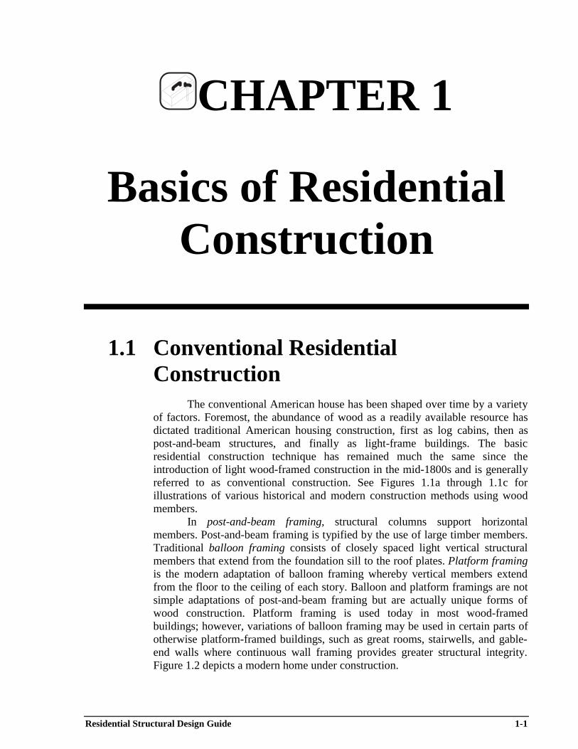
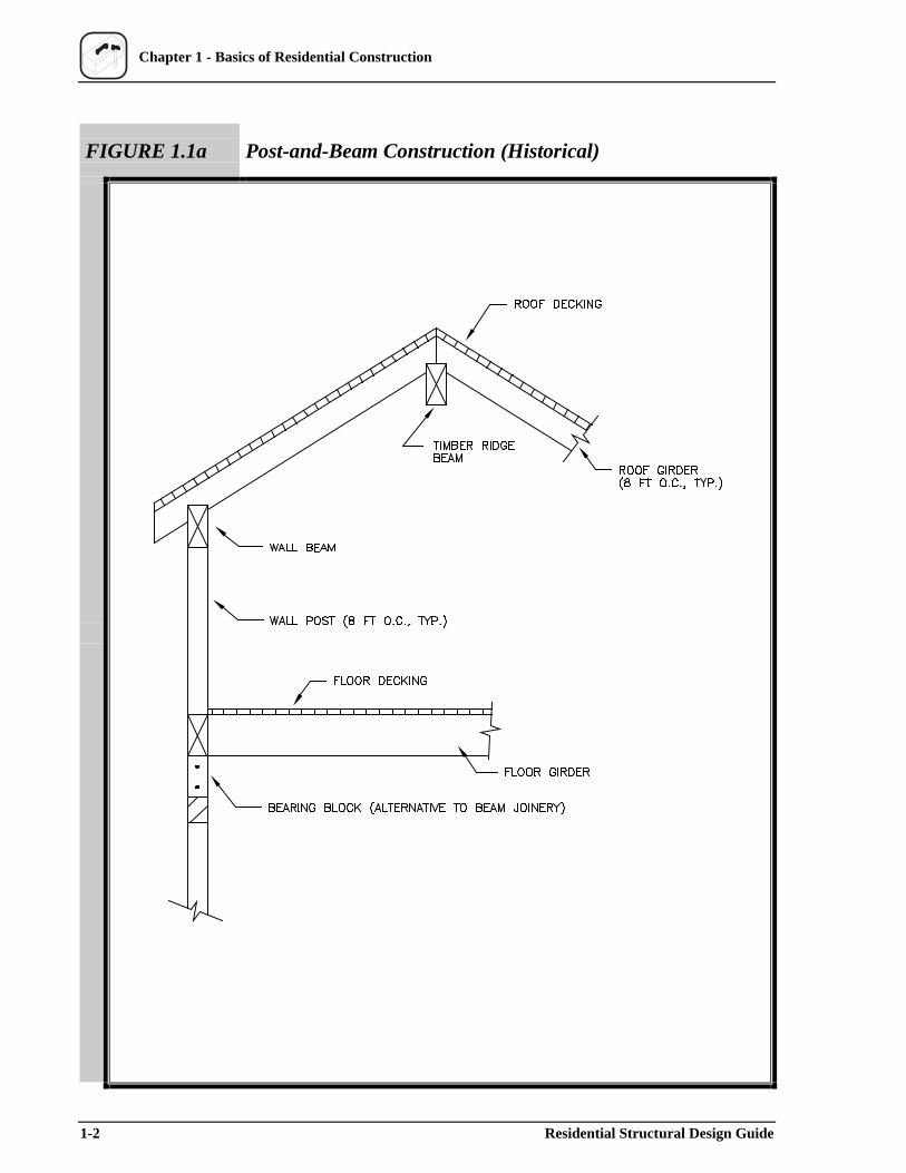
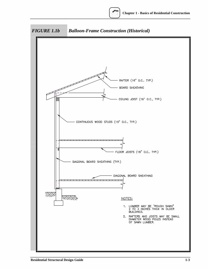
The conventional American house has been shaped over time by a variety of factors. Foremost, the abundance of wood as a readily available resource has dictated traditional American housing construction, first as log cabins, then as post-and-beam structures, and finally as light-frame buildings. The basic residential construction technique has remained much the same since the introduction of light wood-framed construction in the mid-1800s and is generally referred to as conventional construction. See Figures 1.1a through 1.1c for illustrations of various historical and modern construction methods using wood members.
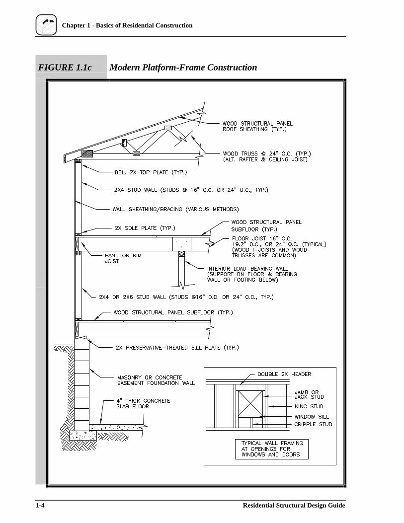
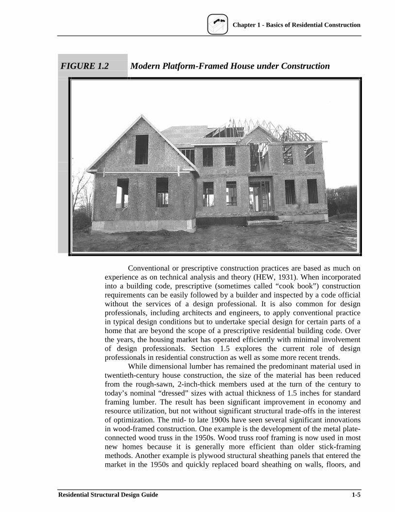
In post-and-beam framing, structural columns support horizontal members. Post-and-beam framing is typified by the use of large timber members. Traditional balloon framing consists of closely spaced light vertical structural members that extend from the foundation sill to the roof plates. Platform framing is the modern adaptation of balloon framing whereby vertical members extend from the floor to the ceiling of each story. Balloon and platform framings are not simple adaptations of post-and-beam framing but are actually unique forms of wood construction. Platform framing is used today in most wood-framed buildings; however, variations of balloon framing may be used in certain parts of otherwise platform-framed buildings, such as great rooms, stairwells, and gable-end walls where continuous wall framing provides greater structural integrity. Figure 1.2 depicts a modern home under construction.
Residential Structural Design Guide 1-1
Chapter 1 - Basics of Residential Construction
FIGURE 1.1a Post-and-Beam Construction (Historical)
1-2 Residential Structural Design Guide
Chapter 1 - Basics of Residential Construction
FIGURE 1.1b Balloon-Frame Construction (Historical)
Residential Structural Design Guide 1-3
Chapter 1 - Basics of Residential Construction
FIGURE 1.1c Modern Platform-Frame Construction
1-4 Residential Structural Design Guide
Chapter 1 - Basics of Residential Construction
FIGURE 1.2 Modern Platform-Framed House under Construction
Conventional or prescriptive construction practices are based as much on experience as on technical analysis and theory (HEW, 1931). When incorporated into a building code, prescriptive (sometimes called “cook book”) construction requirements can be easily followed by a builder and inspected by a code official without the services of a design professional. It is also common for design professionals, including architects and engineers, to apply conventional practice in typical design conditions but to undertake special design for certain parts of a home that are beyond the scope of a prescriptive residential building code. Over the years, the housing market has operated efficiently with minimal involvement of design professionals. Section 1.5 explores the current role of design professionals in residential construction as well as some more recent trends.
While dimensional lumber has remained the predominant material used in twentieth-century house construction, the size of the material has been reduced from the rough-sawn, 2-inch-thick members used at the turn of the century to today’s nominal “dressed” sizes with actual thickness of 1.5 inches for standard framing lumber. The result has been significant improvement in economy and resource utilization, but not without significant structural trade-offs in the interest of optimization. The mid- to late 1900s have seen several significant innovations in wood-framed construction. One example is the development of the metal plate-connected wood truss in the 1950s. Wood truss roof framing is now used in most new homes because it is generally more efficient than older stick-framing methods. Another example is plywood structural sheathing panels that entered the market in the 1950s and quickly replaced board sheathing on walls, floors, and
Residential Structural Design Guide 1-5
Chapter 1 - Basics of Residential Construction
roofs. Another engineered wood product known as oriented strand board (OSB) is now substantially replacing plywood.
In addition, it is important to recognize that while the above changes in materials and methods were occurring, significant changes in house design have continued to creep into the residential market in the way of larger homes with more complicated architectural features, long-span floors and roofs, large open interior spaces, and more amenities. Certainly, the collective effect of the above changes on the structural qualities of most homes is notable.
The references below are recommended for a more in-depth understanding of conventional housing design, detailing, and construction. Section 1.8– References–provides detailed citations.
• Wood Frame House Construction, Second Edition (NAHB, 1992) • Cost-Effective Home Building: A Design and Construction
Handbook (NAHB, 1994) • Modern Carpentry–Building Construction Details in Easy-to-
Understand Form, Seventh Edition (Wagner, 1992) • International One- and Two-Family Dwelling Code (ICC, 1998)
The following structural design references are also recommended for use with Chapters 3 through 7 of this guide:
• NDS–National Design Specification for Wood Construction and Supplement (AF&PA, 1997);
• ACI-318–Building Code Requirements for Structural Concrete (ACI, 1999);
• ACI-530–Building Code Requirements for Masonry Structures (ACI, 1999);
• ASCE 7-98–Minimum Design Loads for Buildings and Other Structures (ASCE, 1999); and
• local building code.
1.2 Industrialized Housing Most homes in the United States are still site-built; that is, they follow a
“stick framing” approach. With this method, wood members are assembled on site in the order of construction from the foundation up. The primary advantage of on-site building is flexibility in meeting variations in housing styles, design details, and changes specified by the owner or builder. However, an increasing number of today’s site-built homes use components that are fabricated in an off-site plant. Prime examples include wall panels and metal plate-connected wood roof trusses. The blend of stick-framing and plant-built components is referred to as "component building."
A step beyond component building is modular housing. Modular housing is constructed in essentially the same manner as site-built housing except that houses are plant-built in finished modules (typically two or more modules) and shipped to the jobsite for placement on conventional foundations. Modular
1-6 Residential Structural Design Guide
Chapter 1 - Basics of Residential Construction
housing is built to comply with the same building codes that govern site-built housing. Generally, modular housing accounts for less than 10 percent of total production of single-family housing units.
Manufactured housing (also called mobile homes) is also constructed by using wood-framed methods; however, the methods comply with federal preemptive standards specified in the Code of Federal Regulations (HUD Code). This popular form of industrialized housing is completely factory-assembled and then delivered to a site by using an integral chassis for road travel and foundation support. In recent years, factory-built housing has captured more than 20 percent of new housing starts in the United States.
1.3 Alternative Materials and Methods More recently, several innovations in structural materials have been
introduced to residential construction. In fact, alternatives to conventional wood-framed construction are gaining recognition in modern building codes. It is important for designers to become familiar with these alternatives since their effective integration into conventional home building may require the services of a design professional. In addition, a standard practice in one region of the country may be viewed as an alternative in another and provides opportunities for innovation across regional norms.
Many options in the realm of materials are already available. The following pages describe several significant examples. In addition, the following contacts are useful for obtaining design and construction information on the alternative materials and methods for house construction discussed next:
General ContactsHUD User (800-245-2691, www.huduser.org)ToolBase (800-898-2842, www.nahbrc.org)
Engineered Wood Products American Wood Council (800-292-2372, www.awc.org) APA–The Engineered Wood Association (206-565-6600, www.apawood.org)Wood Truss Council of America (608-274-4849, www.woodtruss.com)Wood I-Joist Manufacturer’s Association (www.i-joist.com)
Cold-Formed SteelNorth American Steel Framing Alliance (202-785-2022, www.steelframingalliance.com)American Iron and Steel Institute (1-800-898-2842, www.steel.org)Light-Gauge Steel Engineer’s Association (615-386-7139, www.lgsea.com)Steel Truss & Component Association (608-268-1031, www.steeltruss.org)
Insulating Concrete FormsPortland Cement Association (847-966-6200, www.portcement.org)Insulating Concrete Form Association (847-657-9730, www.forms.org)
MasonryNational Concrete Masonry Association (703-713-1900, www.ncma.org)
Residential Structural Design Guide 1-7
Chapter 1 - Basics of Residential Construction
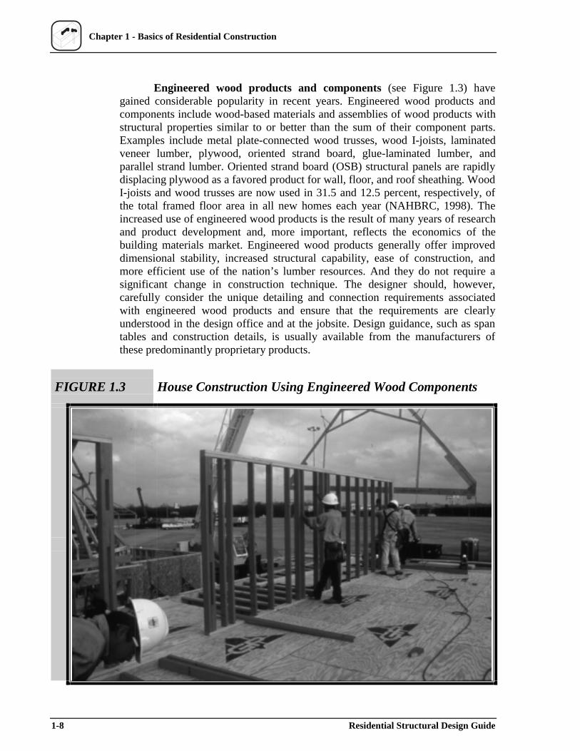
Engineered wood products and components (see Figure 1.3) have gained considerable popularity in recent years. Engineered wood products and components include wood-based materials and assemblies of wood products with structural properties similar to or better than the sum of their component parts. Examples include metal plate-connected wood trusses, wood I-joists, laminated veneer lumber, plywood, oriented strand board, glue-laminated lumber, and parallel strand lumber. Oriented strand board (OSB) structural panels are rapidly displacing plywood as a favored product for wall, floor, and roof sheathing. Wood I-joists and wood trusses are now used in 31.5 and 12.5 percent, respectively, of the total framed floor area in all new homes each year (NAHBRC, 1998). The increased use of engineered wood products is the result of many years of research and product development and, more important, reflects the economics of the building materials market. Engineered wood products generally offer improved dimensional stability, increased structural capability, ease of construction, and more efficient use of the nation’s lumber resources. And they do not require a significant change in construction technique. The designer should, however, carefully consider the unique detailing and connection requirements associated with engineered wood products and ensure that the requirements are clearly understood in the design office and at the jobsite. Design guidance, such as span tables and construction details, is usually available from the manufacturers of these predominantly proprietary products.
FIGURE 1.3 House Construction Using Engineered Wood Components
1-8 Residential Structural Design Guide
Chapter 1 - Basics of Residential Construction
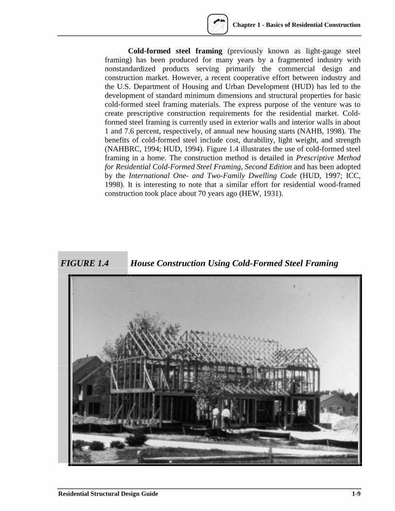
Cold-formed steel framing (previously known as light-gauge steel framing) has been produced for many years by a fragmented industry with nonstandardized products serving primarily the commercial design and construction market. However, a recent cooperative effort between industry and the U.S. Department of Housing and Urban Development (HUD) has led to the development of standard minimum dimensions and structural properties for basic cold-formed steel framing materials. The express purpose of the venture was to create prescriptive construction requirements for the residential market. Cold-formed steel framing is currently used in exterior walls and interior walls in about 1 and 7.6 percent, respectively, of annual new housing starts (NAHB, 1998). The benefits of cold-formed steel include cost, durability, light weight, and strength (NAHBRC, 1994; HUD, 1994). Figure 1.4 illustrates the use of cold-formed steel framing in a home. The construction method is detailed in Prescriptive Method for Residential Cold-Formed Steel Framing, Second Edition and has been adopted by the International One- and Two-Family Dwelling Code (HUD, 1997; ICC, 1998). It is interesting to note that a similar effort for residential wood-framed construction took place about 70 years ago (HEW, 1931).
FIGURE 1.4 House Construction Using Cold-Formed Steel Framing
Residential Structural Design Guide 1-9
Chapter 1 - Basics of Residential Construction
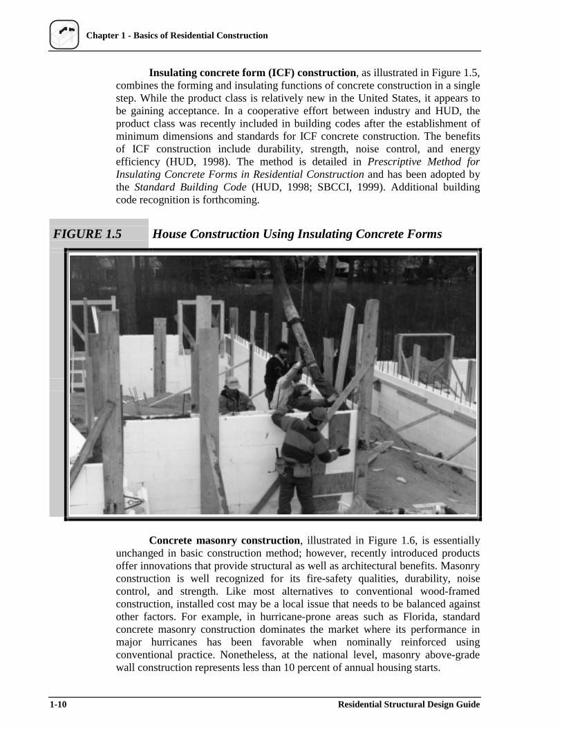
Insulating concrete form (ICF) construction, as illustrated in Figure 1.5, combines the forming and insulating functions of concrete construction in a single step. While the product class is relatively new in the United States, it appears to be gaining acceptance. In a cooperative effort between industry and HUD, the product class was recently included in building codes after the establishment of minimum dimensions and standards for ICF concrete construction. The benefits of ICF construction include durability, strength, noise control, and energy efficiency (HUD, 1998). The method is detailed in Prescriptive Method for Insulating Concrete Forms in Residential Construction and has been adopted by the Standard Building Code (HUD, 1998; SBCCI, 1999). Additional building code recognition is forthcoming.
FIGURE 1.5 House Construction Using Insulating Concrete Forms
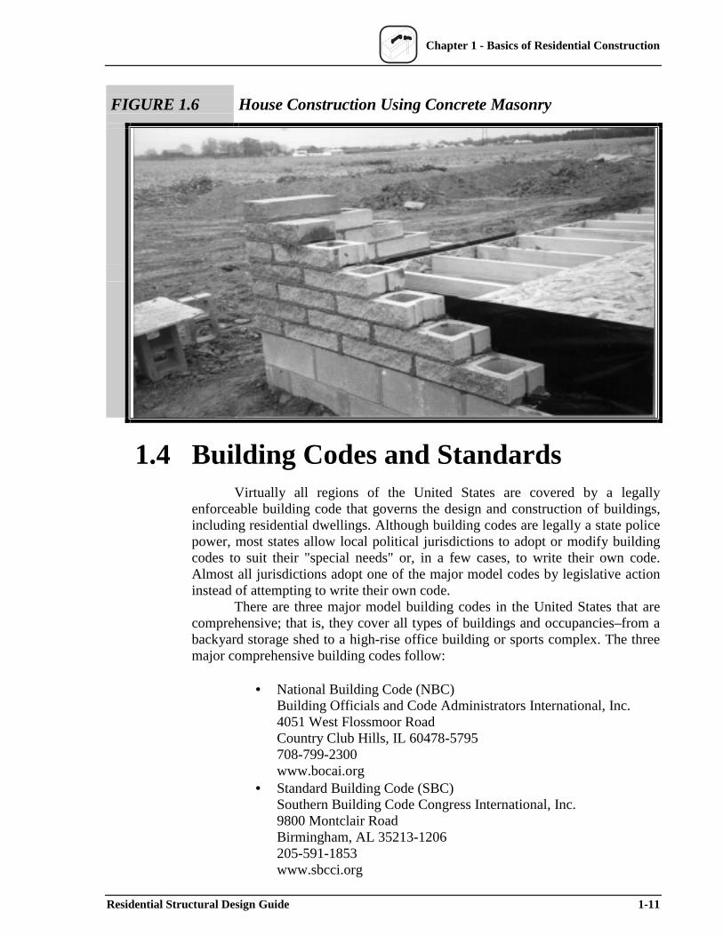
Concrete masonry construction, illustrated in Figure 1.6, is essentially unchanged in basic construction method; however, recently introduced products offer innovations that provide structural as well as architectural benefits. Masonry construction is well recognized for its fire-safety qualities, durability, noise control, and strength. Like most alternatives to conventional wood-framed construction, installed cost may be a local issue that needs to be balanced against other factors. For example, in hurricane-prone areas such as Florida, standard concrete masonry construction dominates the market where its performance in major hurricanes has been favorable when nominally reinforced using conventional practice. Nonetheless, at the national level, masonry above-grade wall construction represents less than 10 percent of annual housing starts.
1-10 Residential Structural Design Guide
Chapter 1 - Basics of Residential Construction
FIGURE 1.6 House Construction Using Concrete Masonry
1.4 Building Codes and Standards Virtually all regions of the United States are covered by a legally
enforceable building code that governs the design and construction of buildings, including residential dwellings. Although building codes are legally a state police power, most states allow local political jurisdictions to adopt or modify building codes to suit their "special needs" or, in a few cases, to write their own code. Almost all jurisdictions adopt one of the major model codes by legislative action instead of attempting to write their own code.
There are three major model building codes in the United States that are comprehensive; that is, they cover all types of buildings and occupancies–from a backyard storage shed to a high-rise office building or sports complex. The three major comprehensive building codes follow:
• National Building Code (NBC) Building Officials and Code Administrators International, Inc. 4051 West Flossmoor Road Country Club Hills, IL 60478-5795 708-799-2300 www.bocai.org
• Standard Building Code (SBC) Southern Building Code Congress International, Inc. 9800 Montclair Road Birmingham, AL 35213-1206 205-591-1853 www.sbcci.org
Residential Structural Design Guide 1-11
Chapter 1 - Basics of Residential Construction
• Uniform Building Code (UBC) International Conference of Building Officials 5360 Workman Mill Road Whittier, CA 90601-2298 562-699-0541 www.icbo.com
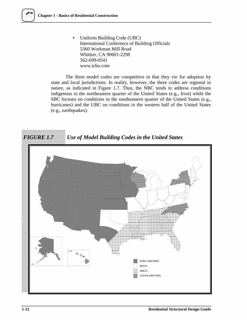
The three model codes are competitive in that they vie for adoption by state and local jurisdictions. In reality, however, the three codes are regional in nature, as indicated in Figure 1.7. Thus, the NBC tends to address conditions indigenous to the northeastern quarter of the United States (e.g., frost) while the SBC focuses on conditions in the southeastern quarter of the United States (e.g., hurricanes) and the UBC on conditions in the western half of the United States (e.g., earthquakes).
FIGURE 1.7 Use of Model Building Codes in the United States
ICBO UNIFORM
BOCA
SBCCI
STATE-WRITTEN
1-12 Residential Structural Design Guide
Chapter 1 - Basics of Residential Construction
To help resolve the problem of disunity among the three major building codes, the model building code organizations have recently entered into a joint effort (under the auspices of the International Code Council or ICC) to develop a single comprehensive building code called the International Building Code (IBC). The IBC is under development at the time of this writing. It draws heavily from the previous codes but adds new requirements for seismic design, wind design, stair geometry, energy conservation, and other vital subject areas. The new code is scheduled to be available in 2000, although several years may pass before change is realized on a national scale. In addition, another code-writing body, the National Fire Protection Association (NFPA), is developing a competitive model building code.
While the major model codes include some "deemed-to-comply" prescriptive requirements for conventional house construction, they focus primarily on performance (i.e., engineering) requirements for more complex buildings across the whole range of occupancy and construction types. To provide a comprehensive, easier-to-use code for residential construction, the three major code organizations participated in developing the International One- and Two-Family Dwelling Code (ICC, 1998), first published in 1971 as the One- and Two-Family Dwelling Code (OTFDC) by the Council of American Building Officials (CABO). Presented in logical construction sequence, the OTFDC is devoted entirely to simple prescriptive requirements for single-family detached and attached (townhouse) homes. Many state and local jurisdictions have adopted the OTFDC as an alternative to a major residential building code. Thus, designers and builders enjoy a choice as to which set of requirements best suits their purpose.
The major code organizations are also developing a replacement for the OTFDC in conjunction with the proposed IBC. Tentatively called the International Residential Code for One- and Two-Family Dwellings (IRC), it draws on earlier editions of the OTFDC and is slated for publication in 2000.
Model building codes do not provide detailed specifications for all building materials and products but rather refer to established industry standards, primarily those promulgated by the American Society for Testing and Materials (ASTM). Several ASTM standards are devoted to the measurement, classification, and grading of wood properties for structural applications as well as virtually all other building materials, including steel, concrete, and masonry. Design standards and guidelines for wood, steel, concrete materials, and other materials or applications are also maintained as reference standards in building codes. Currently, over 600 materials and testing standards are referenced in the building codes used in the United States.
For products and processes not explicitly recognized in the body of any of the model codes or standards, the model building code organizations provide a special code evaluation service with published reports. These evaluation reports are usually provided for a fee at the request of manufacturers. While the National Evaluation Service, Inc. (NES) provides a comprehensive evaluation relative to the three model codes mentioned above, each model code organization also performs evaluations independently for its specific code.
Seasoned designers spend countless hours in careful study and application of building codes and selected standards that relate to their area of practice. More important, these designers develop a sound understanding of the technical
Residential Structural Design Guide 1-13
Chapter 1 - Basics of Residential Construction
rationale and intent behind various provisions in applicable building codes and design standards. This experience and knowledge, however, can become even more profitable when coupled with practical experiences from “the field.” One of the most valuable sources of practical experience is the successes and failures of past designs and construction practices as presented in Section 1.6.
1.5 Role of the Design Professional Since the primary user of this guide is assumed to be a design
professional, it is important to understand the role that design professionals can play in the residential construction process, particularly with respect to recent trends. Design professionals offer a wide range of services to a builder or developer in the areas of land development, environmental impact assessments, geotechnical and foundation engineering, architectural design, structural engineering, and construction monitoring. This guide, however, focuses on two approaches to structural design as follows:
• Conventional design. Sometimes referred to as "nonengineered" construction, conventional design relies on standard practice as governed by prescriptive building code requirements for conventional residential buildings (see Section 1.4); some parts of the structure may be specially designed by an engineer or architect.
• Engineered design. Engineered design generally involves the application of conventions for engineering practice as represented in existing building codes and design standards.
Some of the conditions that typically cause concern in the planning and preconstruction phases of home building and thus sometimes create the need for professional design services are
• structural configurations, such as unusually long floor spans, unsupported wall heights, large openings, or long-span cathedral ceilings;
• loading conditions, such as high winds, high seismic risk, heavy snows, or abnormal equipment loads;
• nonconventional building systems or materials, such as composite materials, structural steel, or unusual connections and fasteners;
• geotechnical or site conditions, such as expansive soil, variable soil or rock foundation bearing, flood-prone areas, high water table, or steeply sloped sites; and
• owner requirements, such as special materials, appliance or fixture loads, atriums, and other special features.
The involvement of architects and structural engineers in the current residential market was recently studied. In a survey of 978 designers (594 architects and 384 structural engineers) in North America, at least 56 percent believed they were qualified to design buildings of four stories or less (Kozak and Cohen, 1999). Of this share, 80 percent noted that their workload was devoted to
1-14 Residential Structural Design Guide
Chapter 1 - Basics of Residential Construction
buildings of four stories or less, with about 33 percent of that workload encompassing residential construction, including single-family dwellings, duplexes, multifamily units, and commercial/residential combinations.
While some larger production builders produce sufficient volume to justify an on-staff design professional, most builders use consultants on an as-needed basis. However, as more and more homes are built along the earthquake-prone West Coast and along the hurricane-prone Gulf and Atlantic seaboards, the involvement of structural design professionals seems to be increasing. Further, the added complexities of larger custom-built homes and special site conditions will spur demand for design specialists. Moreover, if nonconventional materials and methods of construction are to be used effectively, the services of a design professional are often required. In some instances, builders in high-hazard areas are using design professionals for on-site compliance inspections in addition to designing buildings.
The following organization may serve as a valuable on-demand resource for residential designers while creating better linkages with the residential building community and its needs:
REACH Residential Engineer’s and Architect’s Council for HousingNAHB Research Center, Inc.800-898-2842www.nahbrc.org
1.6 Housing Structural Performance
1.6.1 General
There are well over 100 million housing units in the United States, and approximately half are single-family dwellings. Each year, at least 1 million new single-family homes and townhomes are constructed, along with thousands of multifamily structures, most of which are low-rise apartments. Therefore, a small percent of all new residences may be expected to experience performance problems, most of which amount to minor defects that are easily detected and repaired. Other performance problems are unforeseen or undetected and may not be realized for several years, such as foundation problems related to subsurface soil conditions.
On a national scale, several homes are subjected to extreme climatic or geologic events in any given year. Some will be damaged due to a rare event that exceeds the performance expectations of the building code (i.e., a direct tornado strike or a large-magnitude hurricane, thunderstorm, or earthquake). Some problems may be associated with defective workmanship, premature product failure, design flaws, or durability problems (i.e., rot, termites, or corrosion). Often, it is a combination of factors that leads to the most dramatic forms of damage. Because the cause and effect of these problems do not usually fit simple generalizations, it is important to consider cause and effect objectively in terms of the overall housing inventory.
Residential Structural Design Guide 1-15
Chapter 1 - Basics of Residential Construction
To limit the threat of life-threatening performance problems to reasonable levels, the role of building codes is to ensure that an acceptable level of safety is maintained over the life of a house. Since the public cannot benefit from an excessive degree of safety that it cannot afford, code requirements must also maintain a reasonable balance between affordability and safety. As implied by any rational interpretation of a building code or design objective, safety implies the existence of an acceptable level of risk. In this sense, economy or affordability may be broadly considered as a competing performance requirement. For a designer, the challenge is to consider optimum value and to use cost-effective design methods that result in acceptable performance in keeping with the intent or minimum requirements of the building code. In some cases, designers may be able to offer cost-effective options to builders and owners that improve performance well beyond the accepted norm.
1.6.2 Common Performance Issues
Objective information from a representative sample of the housing stock is not available to determine the magnitude and frequency of common performance problems. Instead, information must be gleaned and interpreted from indirect sources.
The following data are drawn from a published study of homeowner warranty insurance records in Canada (ONHWP/CMHC, 1994); similar studies are not easily found in the United States. The data do not represent the frequency of problems in the housing population at large but rather the frequency of various types of problems experienced by those homes that are the subject of an insurance claim. The data do, however, provide valuable insights into the performance problems of greatest concern–at least from the perspective of a homeowner warranty business.
Table 1.1 shows the top five performance problems typically found in Canadian warranty claims based on the frequency and cost of a claim. It may be presumed that claims would be similar in the United States since housing construction is similar, forgoing the difference that may be attributed to climate.
Considering the frequency of claim, the most common claim was for defects in drywall installation and finishing. The second most frequent claim was related to foundation walls; 90 percent of such claims were associated with cracks and water leakage. The other claims were primarily related to installation defects such as missing trim, poor finish, or sticking windows or doors.
In terms of cost to correct, foundation wall problems (usually associated with moisture intrusion) were by far the most costly. The second most costly defect involved the garage slab, which typically cracked in response to frost heaving or settlement. Ceramic floor tile claims (the third most costly claim) were generally associated with poor installation that resulted in uneven surfaces, inconsistent alignment, or cracking. Claims related to septic drain fields were associated with improper grading and undersized leaching fields. Though not shown in Table 1.1, problems in the above-grade structure (i.e., framing defects) resulted in about 6 percent of the total claims reported. While the frequency of structural related defects is comparatively small, the number is still significant in view of the total number of homes built each year. Even if many of the defects
1-16 Residential Structural Design Guide
Chapter 1 - Basics of Residential Construction
may be considered nonconsequential in nature, others may not be and some may go undetected for the life of the structure. Ultimately, the significance of these types of defects must be viewed from the perspective of known consequences relative to housing performance and risk; refer to Sections 1.6.3 and 2.5.4.
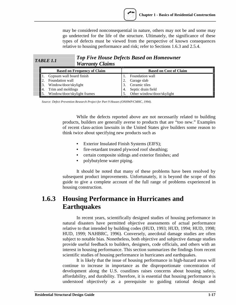
TABLE 1.1 Top Five House Defects Based on Homeowner Warranty Claims
Based on Frequency of Claim Based on Cost of Claim 1. Gypsum wall board finish 1. Foundation wall 2. Foundation wall 2. Garage slab 3. Window/door/skylight 3. Ceramic tiles 4. Trim and moldings 4. Septic drain field 5. Window/door/skylight frames 5. Other window/door/skylight
Source: Defect Prevention Research Project for Part 9 Houses (ONHWP/CMHC, 1994).
While the defects reported above are not necessarily related to building products, builders are generally averse to products that are “too new.” Examples of recent class-action lawsuits in the United States give builders some reason to think twice about specifying new products such as
• Exterior Insulated Finish Systems (EIFS); • fire-retardant treated plywood roof sheathing; • certain composite sidings and exterior finishes; and • polybutylene water piping.
It should be noted that many of these problems have been resolved by subsequent product improvements. Unfortunately, it is beyond the scope of this guide to give a complete account of the full range of problems experienced in housing construction.
1.6.3 Housing Performance in Hurricanes and Earthquakes
In recent years, scientifically designed studies of housing performance in natural disasters have permitted objective assessments of actual performance relative to that intended by building codes (HUD, 1993; HUD, 1994; HUD, 1998; HUD, 1999; NAHBRC, 1996). Conversely, anecdotal damage studies are often subject to notable bias. Nonetheless, both objective and subjective damage studies provide useful feedback to builders, designers, code officials, and others with an interest in housing performance. This section summarizes the findings from recent scientific studies of housing performance in hurricanes and earthquakes.
It is likely that the issue of housing performance in high-hazard areas will continue to increase in importance as the disproportionate concentration of development along the U.S. coastlines raises concerns about housing safety, affordability, and durability. Therefore, it is essential that housing performance is understood objectively as a prerequisite to guiding rational design and
Residential Structural Design Guide 1-17
Chapter 1 - Basics of Residential Construction
construction decisions. Proper design that takes into account the wind and earthquake loads in Chapter 3 and the structural analysis procedures in Chapters 4, 5, 6, and 7 should result in efficient designs that address the performance issues discussed below. Regardless of the efforts made in design, however, the intended performance can be realized only with an adequate emphasis on installed quality. For this reason, some builders in high-hazard areas have retained the services of a design professional for on-site compliance inspections as well as for their design services. This practice offers additional quality assurance to the builder, designer, and owner in high-hazard areas of the country.
Hurricane Andrew
Without doubt, housing performance in major hurricanes provides ample evidence of problems that may be resolved through better design and construction practices. At the same time, misinformation and reaction following major hurricanes often produce a distorted picture of the extent, cause, and meaning of the damage relative to the population of affected structures. This section discusses the actual performance of the housing stock based on a damage survey and engineering analysis of a representative sample of homes subjected to the most extreme winds of Hurricane Andrew (HUD, 1998; HUD, 1993).
Hurricane Andrew struck a densely populated area of south Florida on August 24, 1992, with the peak recorded wind speed exceeding 175 mph (Reinhold, Vickery, and Powell, 1993). At speeds of 160 to 165 mph over a relatively large populated area, Hurricane Andrew was estimated to be about a 300-year return period event (Vickery and Twisdale, 1995; Vickery et al., 1998) (see Figure 1.8). Given the distance between the shoreline and the housing stock, most damage resulted from wind, rain, and wind-borne debris, not from the storm surge. Table 1.2 summarizes the key construction characteristics of the homes that experienced Hurricane Andrew’s highest winds (as shown in Figure 1.8). Most homes were one-story structures with nominally reinforced masonry walls, wood-framed gable roofs, and composition shingle roofing.
Table 1.3 summarizes the key damage statistics for the sampled homes. As expected, the most frequent form of damage was related to windows and roofing, with 77 percent of the sampled homes suffering significant damage to roofing materials. Breakage of windows and destruction of roofing materials led to widespread and costly water damage to interiors and contents.
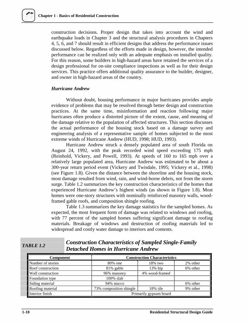
TABLE 1.2Construction Characteristics of Sampled Single-Family Detached Homes in Hurricane Andrew
Component Number of stories Roof construction Wall construction Foundation type Siding material Roofing material Interior finish
Construction Characteristics 80% one 18% two 2% other
81% gable 13% hip 6% other 96% masonry 4% wood-framed
100% slab 94% stucco 6% other
73% composition shingle 18% tile 9% other Primarily gypsum board
1-18 Residential Structural Design Guide
Chapter 1 - Basics of Residential Construction
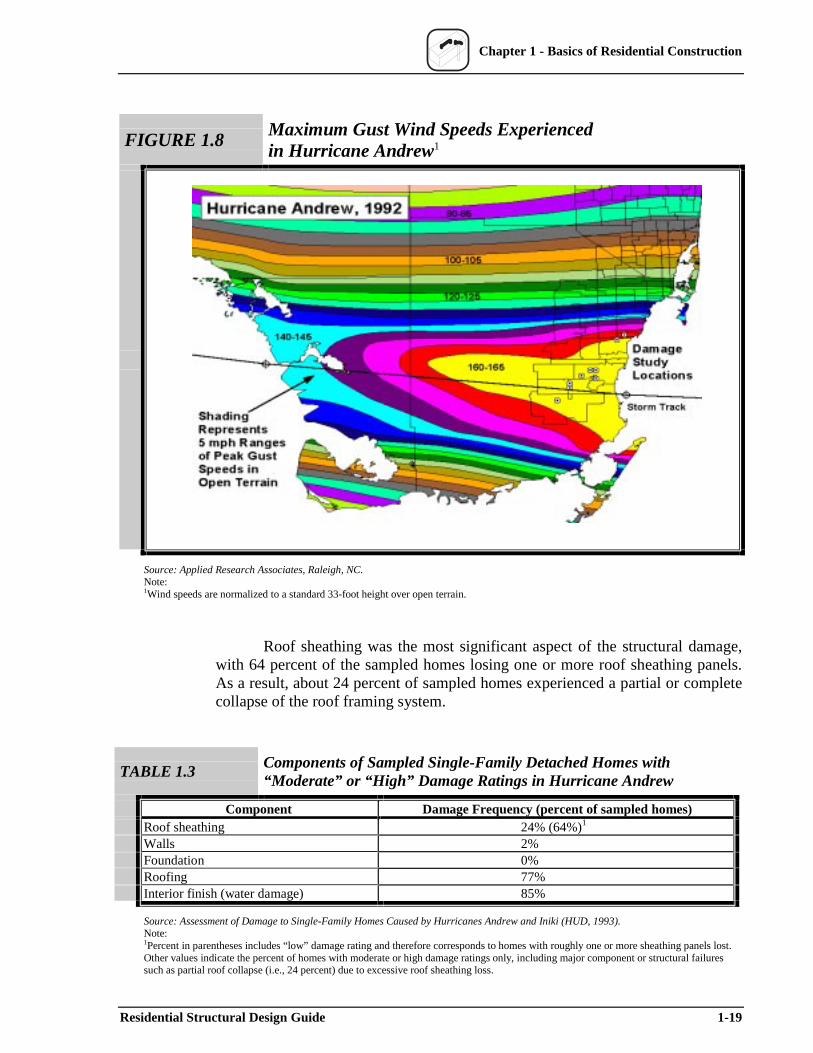
FIGURE 1.8Maximum Gust Wind Speeds Experienced in Hurricane Andrew1
Source: Applied Research Associates, Raleigh, NC. Note:1Wind speeds are normalized to a standard 33-foot height over open terrain.
Roof sheathing was the most significant aspect of the structural damage, with 64 percent of the sampled homes losing one or more roof sheathing panels. As a result, about 24 percent of sampled homes experienced a partial or complete collapse of the roof framing system.
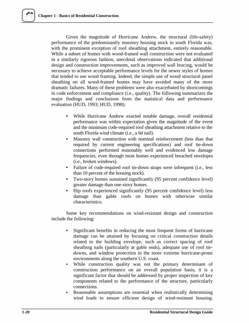
TABLE 1.3 Components of Sampled Single-Family Detached Homes with “Moderate” or “High” Dam age Ratings in Hurricane Andrew
Component Damage Frequency (percent of sampled homes) Roof sheathing 24% (64%)1
Walls 2% Foundation 0% Roofing 77% Interior finish (water damage) 85%
Source: Assessment of Damage to Single-Family Homes Caused by Hurricanes Andrew and Iniki (HUD, 1993). Note:1Percent in parentheses includes “low” damage rating and therefore corresponds to homes with roughly one or more sheathing panels lost.Other values indicate the percent of homes with moderate or high damage ratings only, including major component or structural failuressuch as partial roof collapse (i.e., 24 percent) due to excessive roof sheathing loss.
Residential Structural Design Guide 1-19
Chapter 1 - Basics of Residential Construction
Given the magnitude of Hurricane Andrew, the structural (life-safety) performance of the predominantly masonry housing stock in south Florida was, with the prominent exception of roof sheathing attachment, entirely reasonable. While a subset of homes with wood-framed wall construction were not evaluated in a similarly rigorous fashion, anecdotal observations indicated that additional design and construction improvements, such as improved wall bracing, would be necessary to achieve acceptable performance levels for the newer styles of homes that tended to use wood framing. Indeed, the simple use of wood structural panel sheathing on all wood-framed homes may have avoided many of the more dramatic failures. Many of these problems were also exacerbated by shortcomings in code enforcement and compliance (i.e., quality). The following summarizes the major findings and conclusions from the statistical data and performance evaluation (HUD, 1993; HUD, 1998):
• While Hurricane Andrew exacted notable damage, overall residential performance was within expectation given the magnitude of the event and the minimum code-required roof sheathing attachment relative to the south Florida wind climate (i.e., a 6d nail).
• Masonry wall construction with nominal reinforcement (less than that required by current engineering specifications) and roof tie-down connections performed reasonably well and evidenced low damage frequencies, even through most homes experienced breached envelopes (i.e., broken windows).
• Failure of code-required roof tie-down straps were infrequent (i.e., less than 10 percent of the housing stock).
• Two-story homes sustained significantly (95 percent confidence level) greater damage than one-story homes.
• Hip roofs experienced significantly (95 percent confidence level) less damage than gable roofs on homes with otherwise similar characteristics.
Some key recommendations on wind-resistant design and construction include the following:
• Significant benefits in reducing the most frequent forms of hurricane damage can be attained by focusing on critical construction details related to the building envelope, such as correct spacing of roof sheathing nails (particularly at gable ends), adequate use of roof tie-downs, and window protection in the more extreme hurricane-prone environments along the southern U.S. coast.
• While construction quality was not the primary determinant of construction performance on an overall population basis, it is a significant factor that should be addressed by proper inspection of key components related to the performance of the structure, particularly connections.
• Reasonable assumptions are essential when realistically determining wind loads to ensure efficient design of wind-resistant housing.
1-20 Residential Structural Design Guide
Chapter 1 - Basics of Residential Construction
Assumptions pertain to wind exposure condition, the internal pressure condition, and other factors as addressed later in Chapter 3.
Chapters 3 through 7 present design methods and guidance that address many of the above concerns.
Hurricane Opal
Hurricane Opal struck the Florida panhandle near Pensacola on October 4, 1995, with wind speeds between 100 and 115 mph at peak gust (normalized to an open exposure and elevation of 33 feet) over the sample region of the housing stock (Powell and Houston, 1995). Again, roofing (i.e., shingles) was the most common source of damage, occurring in 4 percent of the sampled housing stock (NAHBRC, 1996). Roof sheathing damage occurred in less than 2 percent of the affected housing stock.
The analysis of Hurricane Opal contrasts sharply with the Hurricane Andrew study. Aside from Hurricane Opal’s much lower wind speeds, most homes were shielded by trees, whereas homes in south Florida were subjected to typical suburban residential exposure with relatively few trees (wind exposure B). Hurricane Andrew denuded any trees in the path of strongest wind. Clearly, housing performance in protected, noncoastal exposures is improved because of the generally less severe wind exposure and the shielding provided when trees are present. However, trees become less reliable sources of protection in more extreme hurricane-prone areas.
Northridge Earthquake
While the performance of houses in earthquakes provides objective data for measuring the acceptability of past and present seismic design and building construction practices, typical damage assessments have been based on “worst-case” observations of the most catastrophic forms of damage, leading to a skewed view of the performance of the overall population of structures. The information presented in this section is, however, based on two related studies that, like the hurricane studies, rely on objective methods to document and evaluate the overall performance of single-family attached and detached dwellings (HUD, 1994; HUD, 1999).
The Northridge Earthquake occurred at 4:31 a.m. on January 17, 1994. Estimates of the severity of the event place it at a magnitude of 6.4 on the Richter scale (Hall, 1994). Although considered a moderately strong tremor, the Northridge Earthquake produced some of the worst ground motions in recorded history for the United States, with estimated return periods of more than 10,000 years. For the most part, these extreme ground motions were highly localized and not necessarily representative of the general near-field conditions that produced ground motions representative of a 200- to 500-year return period event (HUD, 1999).
Table 1.4 summarizes the single-family detached housing characteristics documented in the survey. About 90 percent of the homes in the sample were built before the 1971 San Fernando Valley Earthquake, at which time simple prescriptive requirements were normal for single-family detached home construction. About 60 percent of the homes were built during the 1950s and 1960s, with the rest
Residential Structural Design Guide 1-21
Chapter 1 - Basics of Residential Construction
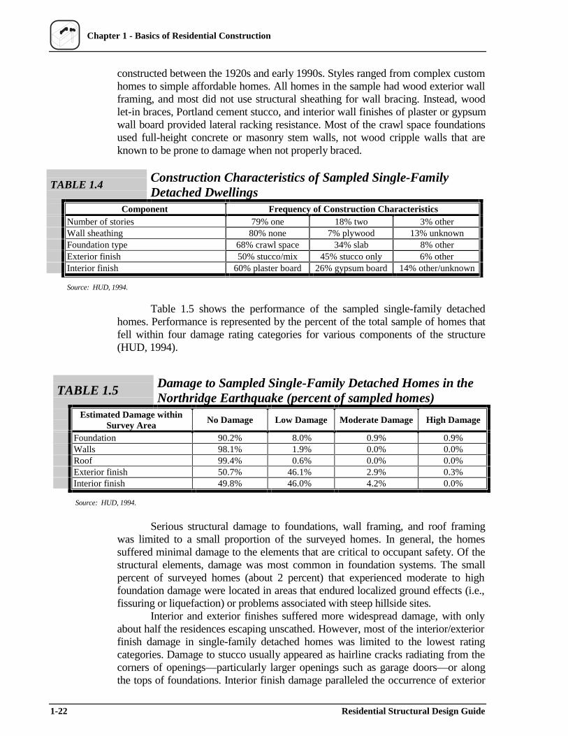
constructed between the 1920s and early 1990s. Styles ranged from complex custom homes to simple affordable homes. All homes in the sample had wood exterior wall framing, and most did not use structural sheathing for wall bracing. Instead, wood let-in braces, Portland cement stucco, and interior wall finishes of plaster or gypsum wall board provided lateral racking resistance. Most of the crawl space foundations used full-height concrete or masonry stem walls, not wood cripple walls that are known to be prone to damage when not properly braced.
TABLE 1.4 Construction Characteristics of Sampled Single-Family Detached Dwellings
Component Frequency of Construction Characteristics Number of stories 79% one 18% two 3% other Wall sheathing 80% none 7% plywood 13% unknown Foundation type 68% crawl space 34% slab 8% other Exterior finish 50% stucco/mix 45% stucco only 6% other Interior finish 60% plaster board 26% gypsum board 14% other/unknown
Source: HUD, 1994.
Table 1.5 shows the performance of the sampled single-family detached homes. Performance is represented by the percent of the total sample of homes that fell within four damage rating categories for various components of the structure (HUD, 1994).
TABLE 1.5 Damage to Sampled Single-Family Detached Homes in the Northridge Earthquake (percent of sampled homes)
Estimated Damage within No Damage Low Damage Moderate Damage High DamageSurvey Area
Foundation 90.2% 8.0% 0.9% 0.9% Walls 98.1% 1.9% 0.0% 0.0% Roof 99.4% 0.6% 0.0% 0.0% Exterior finish 50.7% 46.1% 2.9% 0.3% Interior finish 49.8% 46.0% 4.2% 0.0%
Source: HUD, 1994.
Serious structural damage to foundations, wall framing, and roof framing was limited to a small proportion of the surveyed homes. In general, the homes suffered minimal damage to the elements that are critical to occupant safety. Of the structural elements, damage was most common in foundation systems. The small percent of surveyed homes (about 2 percent) that experienced moderate to high foundation damage were located in areas that endured localized ground effects (i.e., fissuring or liquefaction) or problems associated with steep hillside sites.
Interior and exterior finishes suffered more widespread damage, with only about half the residences escaping unscathed. However, most of the interior/exterior finish damage in single-family detached homes was limited to the lowest rating categories. Damage to stucco usually appeared as hairline cracks radiating from the corners of openings—particularly larger openings such as garage doors—or along the tops of foundations. Interior finish damage paralleled the occurrence of exterior
1-22 Residential Structural Design Guide
Chapter 1 - Basics of Residential Construction
finish (stucco) damage. Resilient finishes—such as wood panel or lap board siding—fared well and often showed no evidence of damage even when stucco on other areas of the same unit was moderately damaged. However, these seemingly minor types of damage were undoubtedly a major source of the economic impact in terms of insurance claims and repair cost. In addition, it is often difficult to separate the damage into categories of “structural” and “nonstructural,” particularly when some systems, such as Portland cement stucco, are used as an exterior cladding as well as structural bracing. It is also important to recognize that the Northridge Earthquake is not considered a “maximum” earthquake event.
The key findings of an evaluation of the above performance data are summarized below (HUD, 1999). Overall, the damage relative to key design features showed no discernable pattern, implying great uncertainties in seismic design and building performance that may not be effectively addressed by simply making buildings “stronger.”
The amount of wall bracing using conventional stucco and let-in braces typically ranged from 30 to 60 percent of the wall length (based on the street-facing walls of the sampled one-story homes). However, there was no observable or statistically significant trend between amount of damage and amount of stucco wall bracing. Since current seismic design theory implies that more bracing is better, the Northridge findings are fundamentally challenging yet offer little in the way of a better design theory. At best, the result may be explained by the fact that numerous factors govern the performance of a particular building in a major seismic event. For example, conventional seismic design, while intending to do so, may not effectively consider the optimization of flexibility, ductility, dampening, and strength–all of which are seemingly important.
The horizontal ground motions experienced over the sample region for the study ranged from 0.26 to 2.7 g for the short-period (0.2 second) spectral response acceleration and from 0.10 to 1.17 g for the long-period (1 second) spectral response acceleration. The near-field ground motions represent a range between the 100- and 14,000-year return period, but a 200- to 500-year return period is more representative of the general ground motion experienced. The short-period ground motion (typically used in the design of light-frame structures) had no apparent correlation with the amount of damage observed in the sampled homes, although a slight trend with respect to the long-period ground motion was observed in the data.
The Northridge damage survey and evaluation of statistical data suggest the following conclusions and recommendations (HUD, 1994; HUD, 1999):
• Severe structural damage to single-family detached homes was infrequent and primarily limited to foundation systems. Less than 2 percent of single-family detached homes suffered moderate to high levels of foundation damage, and most occurrences were associated with localized site conditions, including liquefaction, fissuring, and steep hillsides.
• Structural damage to wall and roof framing in single-family detached homes was limited to low levels for about 2 percent of the walls and for less than 1 percent of all roofs.
• Exterior stucco and interior finishes experienced the most widespread damage, with 50 percent of all single-family detached homes suffering at
Residential Structural Design Guide 1-23

Chapter 1 - Basics of Residential Construction
least minor damage and roughly 4 percent of homes sustaining moderate to high damage. Common finish damage was related to stucco and drywall/plaster cracks emanating from the foundation or wall openings.
• Homes on slab foundations suffered some degree of damage to exterior stucco finishes in about 30 percent of the sample; crawl space homes approached a 60 percent stucco damage rate that was commonly associated with the flexibility of the wall-floor-foundation interface.
• Peak ground motion records in the near-field did not prove to be a significant factor in relation to the level of damage as indicated by the occurrence of stucco cracking. Peak ground acceleration may not of itself be a reliable design parameter in relation to the seismic performance of light-frame homes. Similarly, the amount of stucco wall bracing on street-facing walls showed a negligible relationship with the variable amount of damage experienced in the sampled housing.
Some basic design recommendations call for
• simplifying seismic design requirements to a degree commensurate with knowledge and uncertainty regarding how homes actually perform (see Chapter 3);
• using fully sheathed construction in high-hazard seismic regions (see Chapter 6);
• taking design precautions or avoiding steeply sloped sites or sites with weak soils; and,
• when possible, avoiding brittle interior and exterior wall finish systems in high-hazard seismic regions.
1.7 Summary Housing in the United States has evolved over time under the influence of
a variety of factors. While available resources and the economy continue to play a significant role, building codes, consumer preferences, and alternative construction materials are becoming increasingly important factors. In particular, many local building codes in the United States now require homes to be specially designed rather than following conventional construction practices. In part, this apparent trend may be attributed to changing perceptions regarding housing performance in high-risk areas. Therefore, greater emphasis must be placed on efficient structural design of housing. While efficient design should also strive to improve construction quality through simplified construction, it also places greater importance on the quality of installation required to achieve the intended performance without otherwise relying on “overdesign” to compensate partially for real or perceived problems in installation quality.
1-24 Residential Structural Design Guide
Chapter 1 - Basics of Residential Construction
1.8 References ACI, Building Code Requirements for Masonry Structures, ACI Standard 530,
American Concrete Institute, Farmington Hills, MI, 1999.
ACI, Building Code Requirements for Structural Concrete and Commentary, ACI Standard 318, American Concrete Institute, Farmington Hills, MI, 1999.
AF&PA, National Design Specification for Wood Construction and Supplement, American Forest & Paper Association, Washington, DC, 1997.
ASCE, Minimum Design Loads for Buildings and Other Structures, ASCE Standard 7-98, American Society of Civil Engineers, Reston, VA, 1999.
BOCA, National Building Code (NBC), Building Officials and Code Administrators International, Inc. (BOCA), Country Club Hills, IL, 1999.
HEW, Light Frame House Construction, Vocational Division Bulletin No. 145, U.S. Department of Health, Education, and Welfare (HEW) (GPO: Washington, DC), 1931 (reprinted 1956).
Hall, John F., "Northridge Earthquake January 17, 1994: Preliminary Reconnaissance Report," Earthquake Engineering Research Institute, Oakland, CA, March 1994.
HUD, Alternative Framing Materials in Residential Construction: Three Case Studies, prepared by the NAHB Research Center, Inc., for the U.S. Department of Housing and Urban Development, Washington, DC, 1994.
HUD, Assessment of Damage to Residential Buildings Caused by the Northridge Earthquake, prepared by the NAHB Research Center, Inc., for the U.S. Department of Housing and Urban Development, Washington, DC, 1994.
HUD, Assessment of Damage to Single-Family Homes Caused by Hurricanes Andrew and Iniki, prepared by the NAHB Research Center, Inc., for the U.S. Department of Housing and Urban Development, Washington, DC, 1993.
HUD, Evaluation of Housing Performance and Seismic Design Implications in the Northridge Earthquake, prepared by the NAHB Research Center, Inc., for the U.S. Department of Housing and Urban Development, Washington, DC, 1999.
HUD, Insulating Concrete Forms: Installed Cost and Acoustic Performance, prepared by the NAHB Research Center, Inc., for the Portland Cement Association, National Association of Home Builders, and U.S. Department of Housing and Urban Development, Washington, DC, 1998.
Residential Structural Design Guide 1-25
Chapter 1 - Basics of Residential Construction
HUD, Prescriptive Method for Insulating Concrete Forms in Residential Construction, prepared by the NAHB Research Center, Inc., for the Portland Cement Association, National Association of Home Builders, and U.S. Department of Housing and Urban Development, Washington, DC, 1998.
HUD, Prescriptive Method for Residential Cold-Formed Steel Framing, Second Edition, prepared by the NAHB Research Center, Inc., for the American Iron and Steel Institute, National Association of Home Builders, and U.S. Department of Housing and Urban Development, Washington, DC, 1997.
HUD, Reliability of Conventional Residential Construction: An Assessment of Roof Component Performance in Hurricane Andrew and Typical Wind Regions of the United States, prepared by the NAHB Research Center, Inc., for the U.S. Department of Housing and Urban Development, Washington, DC, 1998.
ICBO, Uniform Building Code (UBC), International Conference of Building Officials (ICBO), Whittier, CA, 1997.
ICC, International Building Code–2000 Edition, International Code Council, Inc., Falls Church, VA, 1999 (final draft).
ICC, International One- and Two-Family Dwelling Code, International Code Council, Inc., Falls Church, VA, 1998.
ICC, International Residential Code for One- and Two-Family Dwellings–2000 Edition, International Code Council, Inc., Falls Church, VA, 1999 (final draft).
Kozak, R. and Cohen, D., “Architects and Structural Engineers: An Examination of Wood Design and Use in Nonresidential Construction,” Forest Products Journal, Vol. 49 No. 4., April 1999, 37-46.
NAHB, Cost-Effective Home Building: A Design and Construction Handbook, prepared by the NAHB Research Center, Inc., for the National Association of Home Builders (NAHB), Washington, DC, 1994.
NAHB, Wood Frame House Construction, Second Edition, edited by Robert Stroh, Ph.D., and Gerald Sherwood, P.E., Delmar Publications and NAHB Home Builder Press, Washington, DC, 1992.
NAHBRC, Assessment of Damage to Homes Caused by Hurricane Opal, prepared for the Florida State Home Builders Association by the NAHB Research Center, Inc., Upper Marlboro, MD, 1996.
NAHBRC, Building with Alternatives to Lumber and Plywood, NAHB Research Center, Inc., and Home Builder Press, Washington, DC, 1994.
1-26 Residential Structural Design Guide
Chapter 1 - Basics of Residential Construction
NAHBRC, Survey of Builder Practices, NAHB Research Center, Inc., Upper Marlboro, MD, 1998.
ONHWP/CMHC, Defect Prevention Research Project for Part 9 Houses, Final Report, prepared for the Ontario New Home Warranty Program (ONHWP) and Canada Mortgage and Housing Corporation (CMHC) by Protor & Redfern Ltd., Don Mills, Ontario, October 1993 (revised November 1994).
Powell, M.D. and Houston, S.H., “Hurricane Opal at Landfall: A Complex Surface Wind Field,” preliminary draft, NOAA–Hurricane Research Division, Miami, FL, December 18, 1995.
Reinhold, T.A., Vickery, P.J., and Powell, M.D. “Windspeeds in Hurricane Andrew: Myths and Reality,” 7th U.S. National Conference on Wind Engineering, University of California, Los Angeles, CA, 1993, 553-562.
SBCCI, Standard Building Code (SBC), Southern Building Code Congress International, Inc. (SBCCI), Birmingham, AL, 1999.
Vickery, P.J., Skerlj, P.F., Steckley, A.C., and Twisdale, L.A., Simulation of Hurricane Risk in the United States Using an Empirical Storm Track Modeling Technique, Applied Research Associates, Raleigh, NC, 1998.
Vickery, P.J. and Twisdale, L.A., “Prediction of Hurricane Wind Speeds in the United States,” Journal of Structural Engineering, American Society of Civil Engineers, Reston, VA, November 1995, 1691-1699.
Wagner, Willis H., Modern Carpentry–Building Construction Details in Easy-to-Understand Form, Goodheart-Willcox Company, Inc., South Holland, IL, 1992.
Residential Structural Design Guide 1-27
Chapter 1 - Basics of Residential Construction
1-28 Residential Structural Design Guide
y
x CHAPTER 2
Structural DesignConcepts
2.1 General This chapter reviews some fundamental concepts of structural design and
presents them in a manner relevant to the design of light-frame residential structures. The concepts form the basis for understanding the design procedures and overall design approach addressed in the remaining chapters of the guide. With this conceptual background, it is hoped that the designer will gain a greater appreciation for creative and efficient design of homes, particularly the many assumptions that must be made.
2.2 What Is Structural Design? The process of structural design is simple in concept but complex in detail.
It involves the analysis of a proposed structure to show that its resistance or strength will meet or exceed a reasonable expectation. This expectation is usually expressed by a specified load or demand and an acceptable margin of safety that constitutes a performance goal for a structure.
The performance goals of structural design are multifaceted. Foremost, a structure must perform its intended function safely over its useful life. Safety is discussed later in this chapter. The concept of useful life implies considerations of durability and establishes the basis for considering the cumulative exposure to time-varying risks (i.e., corrosive environments, occupant loads, snow loads, wind loads, and seismic loads). Given, however, that performance is inextricably linked to cost, owners, builders, and designers must consider economic limits to the primary goals of safety and durability.
The appropriate balance between the two competing considerations of performance and cost is a discipline that guides the “art” of determining value in building design and construction. However, value is judged by the “eye of the
Residential Structural Design Guide 2-1
y
x Chapter 2 – Structural Design Concepts
beholder,” and what is an acceptable value to one person may not be acceptable value to another (i.e., too costly versus not safe enough or not important versus important). For this reason, political processes mediate minimum goals for building design and structural performance, with minimum value decisions embodied in building codes and engineering standards that are adopted as law.
In view of the above discussion, a structural designer may appear to have little control over the fundamental goals of structural design, except to comply with or exceed the minimum limits established by law. While this is generally true, a designer can still do much to optimize a design through alternative means and methods that call for more efficient analysis techniques, creative design detailing, and the use of innovative construction materials and methods.
In summary, the goals of structural design are generally defined by law and reflect the collective interpretation of general public welfare by those involved in the development and local adoption of building codes. The designer's role is to meet the goals of structural design as efficiently as possible and to satisfy a client’s objectives within the intent of the building code. Designers must bring to bear the fullest extent of their abilities, including creativity, knowledge, experience, judgment, ethics, and communication–aspects of design that are within the control of the individual designer and integral to a comprehensive approach to design. Structural design is much, much more than simply crunching numbers.
2.3 Load Conditions and Structural System Response
The concepts presented in this section provide an overview of building loads and their effect on the structural response of typical wood-framed homes. As shown in Table 2.1, building loads can be divided into two types based on the orientation of the structural actions or forces that they induce: vertical loads and horizontal (i.e., lateral) loads.
TABLE 2.1 Building Loads Categorized by Orientation
Vertical Loads Horizontal (Lateral) Loads
• Dead (gravity) • Wind • Live (gravity) • Seismic (horizontal ground motion) • Snow (gravity) • Flood (static and dynamic hydraulic forces) • Wind (uplift on roof) • Soil (active lateral pressure) • Seismic and wind (overturning) • Seismic (vertical ground motion)
2-2 Residential Structural Design Guide
y
x Chapter 2 – Structural Design Concepts
2.3.1 Vertical Loads
Gravity loads act in the same direction as gravity (i.e., downward or vertically) and include dead, live, and snow loads. They are generally static in nature and usually considered a uniformly distributed or concentrated load. Thus, determining a gravity load on a beam or column is a relatively simple exercise that uses the concept of tributary areas to assign loads to structural elements. The tributary area is the area of the building construction that is supported by a structural element, including the dead load (i.e., weight of the construction) and any applied loads (i.e., live load). For example, the tributary gravity load on a floor joist would include the uniform floor load (dead and live) applied to the area of floor supported by the individual joist. The structural designer then selects a standard beam or column model to analyze bearing connection forces (i.e., reactions), internal stresses (i.e., bending stresses, shear stresses, and axial stresses), and stability of the structural member or system; refer to Appendix A for beam equations. The selection of an appropriate analytic model is, however, no trivial matter, especially if the structural system departs significantly from traditional engineering assumptions that are based on rigid body and elastic behavior. Such departures from traditional assumptions are particularly relevant to the structural systems that comprise many parts of a house, but to varying degrees.
Wind uplift forces are generated by negative (suction) pressures acting in an outward direction from the surface of the roof in response to the aerodynamics of wind flowing over and around the building. As with gravity loads, the influence of wind uplift pressures on a structure or assembly (i.e., roof) are analyzed by using the concept of tributary areas and uniformly distributed loads. The major difference is that wind pressures act perpendicular to the building surface (not in the direction of gravity) and that pressures vary according to the size of the tributary area and its location on the building, particularly proximity to changes in geometry (e.g., eaves, corners, and ridges). Even though the wind loads are dynamic and highly variable, the design approach is based on a maximum static load (i.e., pressure) equivalent.
Vertical forces are also created by overturning reactions due to wind and seismic lateral loads acting on the overall building and its lateral force resisting systems. Earthquakes also produce vertical ground motions or accelerations which increase the effect of gravity loads. However, vertical earthquake loads are usually considered to be implicitly addressed in the gravity load analysis of a light-frame building.
2.3.2 Lateral Loads
The primary loads that produce lateral forces on buildings are attributable to forces associated with wind, seismic ground motion, floods, and soil. Wind and seismic lateral loads apply to the entire building. Lateral forces from wind are generated by positive wind pressures on the windward face of the building and by negative pressures on the leeward face of the building, creating a combined push-and-pull effect. Seismic lateral forces are generated by a structure’s dynamic inertial response to cyclic ground movement. The magnitude of the seismic shear
Residential Structural Design Guide 2-3
y
x Chapter 2 – Structural Design Concepts
(i.e., lateral) load depends on the magnitude of the ground motion, the building’s mass, and the dynamic structural response characteristics (i.e., dampening, ductility, natural period of vibration, etc.). For houses and other similar low-rise structures, a simplified seismic load analysis employs equivalent static forces based on fundamental Newtonian mechanics (F=ma) with somewhat subjective (i.e., experience-based) adjustments to account for inelastic, ductile response characteristics of various building systems. Flood loads are generally minimized by elevating the structure on a properly designed foundation or avoided by not building in a flood plain. Lateral loads from moving flood waters and static hydraulic pressure are substantial. Soil lateral loads apply specifically to foundation wall design, mainly as an “out-of-plane” bending load on the wall.
Lateral loads also produce an overturning moment that must be offset by the dead load and connections of the building. Therefore, overturning forces on connections designed to restrain components from rotating or the building from overturning must be considered. Since wind is capable of generating simultaneous roof uplift and lateral loads, the uplift component of the wind load exacerbates the overturning tension forces due to the lateral component of the wind load. Conversely, the dead load may be sufficient to offset the overturning and uplift forces as is often the case in lower design wind conditions and in many seismic design conditions.
2.3.3 Structural Systems
As far back as 1948, it was determined that “conventions in general use for wood, steel and concrete structures are not very helpful for designing houses because few are applicable” (NBS, 1948). More specifically, the NBS document encourages the use of more advanced methods of structural analysis for homes. Unfortunately, the study in question and all subsequent studies addressing the topic of system performance in housing have not led to the development or application of any significant improvement in the codified design practice as applied to housing systems. This lack of application is partly due to the conservative nature of the engineering process and partly due to the difficulty of translating the results of narrowly-focused structural systems studies to general design applications. Since this document is narrowly scoped to address residential construction, relevant system-based studies and design information for housing are discussed, referenced, and applied as appropriate.
If a structural member is part of a system, as is typically the case in light-frame residential construction, its response is altered by the strength and stiffness characteristics of the system as a whole. In general, system performance includes two basic concepts known as load sharing and composite action. Load sharing is found in repetitive member systems (i.e., wood framing) and reflects the ability of the load on one member to be shared by another or, in the case of a uniform load, the ability of some of the load on a weaker member to be carried by adjacent members. Composite action is found in assemblies of components that, when connected to one another, form a “composite member” with greater capacity and stiffness than the sum of the component parts. However, the amount of composite action in a system depends on the manner in which the various system elements are connected. The aim is to achieve a higher effective section modulus than the
2-4 Residential Structural Design Guide
y
x Chapter 2 – Structural Design Concepts
component members taken separately. For example, when floor sheathing is nailed and glued to floor joists, the floor system realizes a greater degree of composite action than a floor with sheathing that is merely nailed; the adhesive between components helps prevent shear slippage, particularly if a rigid adhesive is used. Slippage due to shear stresses transferred between the component parts necessitates consideration of partial composite action, which depends on the stiffness of an assembly’s connections. Therefore, consideration of the floor as a system of fully composite T-beams may lead to an unconservative solution whereas the typical approach of only considering the floor joist member without composite system effect will lead to a conservative design.
This guide addresses the strength-enhancing effect of load sharing and partial composite action when information is available for practical design guidance. Establishment of repetitive-member increase factors (also called system factors) for general design use is a difficult task because the amount of system effect can vary substantially depending on system assembly and materials. Therefore, system factors for general design use are necessarily conservative to cover broad conditions. Those that more accurately depict system effects also require a more exact description of and compliance with specific assembly details and material specifications.
It should be recognized, however, that system effects do not only affect the strength and stiffness of light-frame assemblies (including walls, floors, and roofs). They also alter the classical understanding of how loads are transferred among the various assemblies of a complex structural system, including a complete wood-framed home. For example, floor joists are sometimes doubled under nonload-bearing partition walls "because of the added dead load and resulting stresses" determined in accordance with accepted engineering practice. Such practice is based on a conservative assumption regarding the load path and the structural response. That is, the partition wall does create an additional load, but the partition wall is relatively rigid and actually acts as a deep beam, particularly when the top and bottom are attached to the ceiling and floor framing, respectively. As the floor is loaded and deflects, the interior wall helps resist the load. Of course, the magnitude of effect depends on the wall configuration (i.e., amount of openings) and other factors.
The above example of composite action due to the interaction of separate structural systems or subassemblies points to the improved structural response of the floor system such that it is able to carry more dead and live load than if the partition wall were absent. One whole-house assembly test has demonstrated this effect (Hurst, 1965). Hence, a double joist should not be required under a typical nonload-bearing partition; in fact, a single joist may not even be required directly below the partition, assuming that the floor sheathing is adequately specified to support the partition between the joists. While this condition cannot yet be duplicated in a standard analytic form conducive to simple engineering analysis, a designer should be aware of the concept when making design assumptions regarding light-frame residential construction.
At this point, the reader should consider that the response of a structural system, not just its individual elements, determines the manner in which a structure distributes and resists horizontal and vertical loads. For wood-framed systems, the departure from calculations based on classical engineering mechanics
Residential Structural Design Guide 2-5
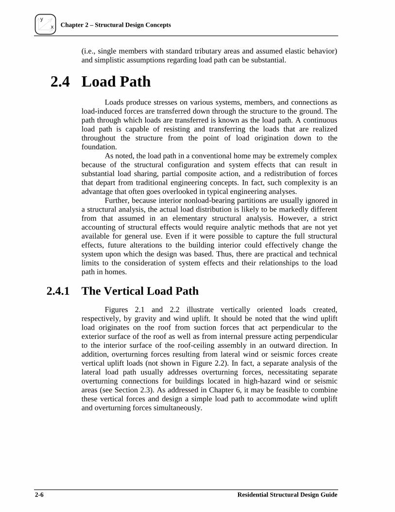
y
x Chapter 2 – Structural Design Concepts
(i.e., single members with standard tributary areas and assumed elastic behavior) and simplistic assumptions regarding load path can be substantial.
2.4 Load Path Loads produce stresses on various systems, members, and connections as
load-induced forces are transferred down through the structure to the ground. The path through which loads are transferred is known as the load path. A continuous load path is capable of resisting and transferring the loads that are realized throughout the structure from the point of load origination down to the foundation.
As noted, the load path in a conventional home may be extremely complex because of the structural configuration and system effects that can result in substantial load sharing, partial composite action, and a redistribution of forces that depart from traditional engineering concepts. In fact, such complexity is an advantage that often goes overlooked in typical engineering analyses.
Further, because interior nonload-bearing partitions are usually ignored in a structural analysis, the actual load distribution is likely to be markedly different from that assumed in an elementary structural analysis. However, a strict accounting of structural effects would require analytic methods that are not yet available for general use. Even if it were possible to capture the full structural effects, future alterations to the building interior could effectively change the system upon which the design was based. Thus, there are practical and technical limits to the consideration of system effects and their relationships to the load path in homes.
2.4.1 The Vertical Load Path
Figures 2.1 and 2.2 illustrate vertically oriented loads created, respectively, by gravity and wind uplift. It should be noted that the wind uplift load originates on the roof from suction forces that act perpendicular to the exterior surface of the roof as well as from internal pressure acting perpendicular to the interior surface of the roof-ceiling assembly in an outward direction. In addition, overturning forces resulting from lateral wind or seismic forces create vertical uplift loads (not shown in Figure 2.2). In fact, a separate analysis of the lateral load path usually addresses overturning forces, necessitating separate overturning connections for buildings located in high-hazard wind or seismic areas (see Section 2.3). As addressed in Chapter 6, it may be feasible to combine these vertical forces and design a simple load path to accommodate wind uplift and overturning forces simultaneously.
2-6 Residential Structural Design Guide
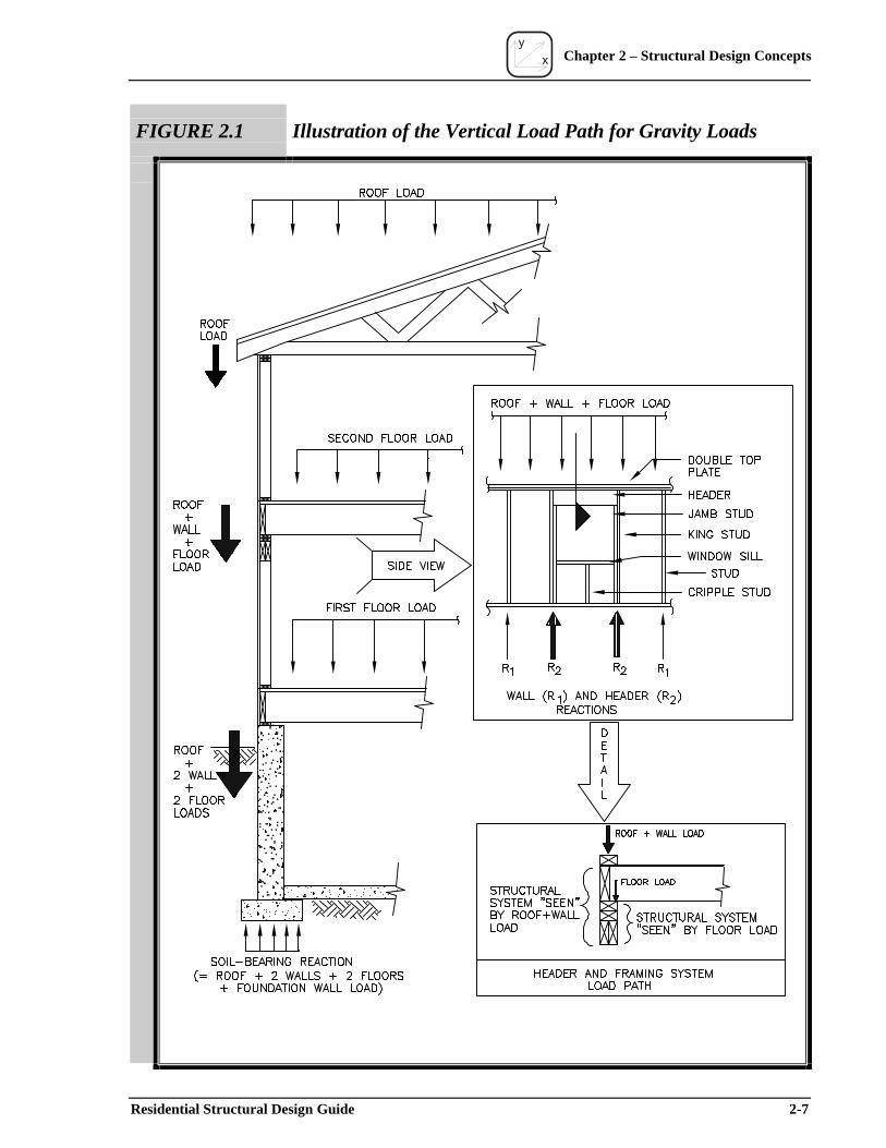
y
x Chapter 2 – Structural Design Concepts
FIGURE 2.1 Illustration of the Vertical Load Path for Gravity Loads
Residential Structural Design Guide 2-7
y
x Chapter 2 – Structural Design Concepts
FIGURE 2.2 Illustration of the Vertical Load Path for Wind Uplift
2-8 Residential Structural Design Guide
y
x Chapter 2 – Structural Design Concepts
In a typical two-story home, the load path for gravity loads and wind uplift involves the following structural elements:
• roof sheathing; • roof sheathing attachment; • roof framing member (rafter or truss); • roof-to-wall connection; • second-story wall components (top plate, studs, sole plate, headers,
wall sheathing, and their interconnections); • second-story-wall-to-second-floor connection; • second-floor-to-first-story-wall connection; • first-story wall components (same as second story); • first-story-wall-to-first-floor or foundation connection; • first-floor-to-foundation connection; and • foundation construction.
From the above list, it is obvious that there are numerous members, assemblies, and connections to consider in tracking the gravity and wind uplift load paths in a typical wood-framed home. The load path itself is complex, even for elements such as headers that are generally considered simple beams. Usually, the header is part of a structural system (see Figure 2.1), not an individual element single-handedly resisting the entire load originating from above. Thus, a framing system around a wall opening, not just a header, comprises a load path.
Figure 2.1 also demonstrates the need for appropriately considering the combination of loads as the load moves “down” the load path. Elements that experience loads from multiple sources (e.g., the roof and one or more floors) can be significantly overdesigned if design loads are not proportioned or reduced to account for the improbability that all loads will occur at the same time. Of course, the dead load is always present, but the live loads are transient; even when one floor load is at its life-time maximum, it is likely that the others will be at only a fraction of their design load. Current design load standards generally allow for multiple transient load reductions. However, with multiple transient load reduction factors intended for general use, they may not effectively address conditions relevant to a specific type of construction (i.e., residential).
Consider the soil-bearing reaction at the bottom of the footing in Figure 2.1. As implied by the illustration, the soil-bearing force is equivalent to the sum of all tributary loads–dead and live. However, it is important to understand the combined load in the context of design loads. Floor design live loads are based on a life-time maximum estimate for a single floor in a single level of a building. But, in the case of homes, the upper and lower stories or occupancy conditions typically differ. When one load is at its maximum, the other is likely to be at a fraction of its maximum. Yet, designers are not able to consider the live loads of the two floors as separate transient loads because specific guidance is not currently available. In concept, the combined live load should therefore be reduced by an appropriate factor, or one of the loads should be set at a point-in-time value that is a fraction of its design live load. For residential construction, the floor design live load is either 30 psf (for bedroom areas) or 40 psf (for other areas), although some codes require a design floor live load of 40 psf for all areas.
Residential Structural Design Guide 2-9
y
x Chapter 2 – Structural Design Concepts
In contrast, average sustained live loads during typical use conditions are about 6 psf (with one standard deviation of 3 psf), which is about 15 to 20 percent of the design live load (Chalk and Corotis, 1980). If actual loading conditions are not rationally considered in a design, the result may be excessive footing widths, header sizes, and so forth.
When tracking the wind uplift load path (Figure 2.2), the designer must consider the offsetting effect of the dead load as it increases down the load path. However, it should be noted that building codes and design standards do not permit the consideration of any part of the sustained live load in offsetting wind uplift, even though it is highly probable that some minimum point-in-time value of floor live load is present if the building is in use, i.e., furnished and/or occupied. In addition, other “nonengineered” load paths, such as provided by interior walls and partitions, are not typically considered. While these are prudent limits, they help explain why certain structures may not “calculate” but otherwise perform adequately.
Depending on the code, it is also common to consider only two-thirds of the dead load when analyzing a structure’s net wind uplift forces. The two-thirds provision is a way of preventing the potential error of requiring insufficient connections where a zero uplift value is calculated in accordance with a nominal design wind load (as opposed to the ultimate wind event that is implied by the use of a safety margin for material strength in unison with a nominal design wind speed). Furthermore, code developers have expressed a concern that engineers might overestimate actual dead loads.
For complicated house configurations, a load of any type may vary considerably at different points in the structure, necessitating a decision of whether to design for the worst case or to accommodate the variations. Often the worst-case condition is applied to the entire structure even when only a limited part of the structure is affected. For example, a floor joist or header may be sized for the worst-case span and used throughout the structure. The worst-case decision is justified only when the benefit of a more intensive design effort is not offset by a significant cost reduction. It is also important to be mindful of the greater construction complexity that usually results from a more detailed analysis of various design conditions. Simplification and cost reduction are both important design objectives, but they may often be mutually exclusive. However, the consideration of system effects in design, as discussed earlier, may result in both simplification and cost efficiencies that improve the quality of the finished product.
One helpful attribute of traditional platform-framed home construction is that the floor and roof gravity loads are typically transferred through bearing points, not connections. Thus, connections may contribute little to the structural performance of homes with respect to vertical loads associated with gravity (i.e., dead, live, and snow loads). While outdoor deck collapses have occurred on occasion, the failure in most instances is associated with an inadequate or deteriorated connection to the house, not a bearing connection.
By contrast, metal plate-connected roof and floor trusses rely on connections to resist gravity loads, but these engineered components are designed and produced in accordance with a proven standard and are generally highly reliable (TPI, 1996). Indeed, the metal plate-connected wood truss was first conceived in Florida in the 1950s to respond to the need for improved roof
2-10 Residential Structural Design Guide
y
x Chapter 2 – Structural Design Concepts
structural performance, particularly with respect to connections in roof construction (WTCA, 1998).
In high-wind climates where the design wind uplift load approaches the offsetting dead load, the consideration of connection design in wood-framed assemblies becomes critical for roofs, walls, and floors. In fact, the importance of connections in conventionally built homes is evidenced by the common loss of weakly attached roof sheathing or roofs in extreme wind events such as moderate-to large-magnitude hurricanes.
Newer prescriptive code provisions have addressed many of the historic structural wind damage problems by specifying more stringent general requirements (SBCCI, 1999; AF&PA, 1996). In many cases, the newer high-wind prescriptive construction requirements may be improved by more efficient site-specific design solutions that consider wind exposure, system effects, and other analytic improvements. The same can be said for prescriptive seismic provisions found in the latest building codes for conventional residential construction (ICC, 1999; ICBO, 1997).
2.4.2 Lateral Load Path
The overall system that provides lateral resistance and stability to a building is known as the lateral force resisting system (LFRS). In light-frame construction, the LFRS includes shear walls and horizontal diaphragms. Shear walls are walls that are typically braced or clad with structural sheathing panels to resist racking forces. Horizontal diaphragms are floor and roof assemblies that are also usually clad with structural sheathing panels. Though more complicated and difficult to visualize, the lateral forces imposed on a building from wind or seismic action also follow a load path that distributes and transfers shear and overturning forces from lateral loads. The lateral loads of primary interest are those resulting from
• the horizontal component of wind pressures on the building’s exterior surface area; and
• the inertial response of a building’s mass and structural system to seismic ground motions.
As seen in Figure 2.3, the lateral load path in wood-framed construction involves entire structural assemblies (i.e., walls, floors, and roofs) and their interconnections, not just individual elements or frames as would be the case with typical steel or concrete buildings that use discrete braced framing systems. The distribution of loads in Figure 2.3’s three-dimensional load path depends on the relative stiffness of the various components, connections, and assemblies that comprise the LFRS. To complicate the problem further, stiffness is difficult to determine due to the nonlinearity of the load-displacement characteristics of wood-framed assemblies and their interconnections. Figure 2.4 illustrates a deformed light-frame building under lateral load; the deformations are exaggerated for conceptual purposes.
Residential Structural Design Guide 2-11
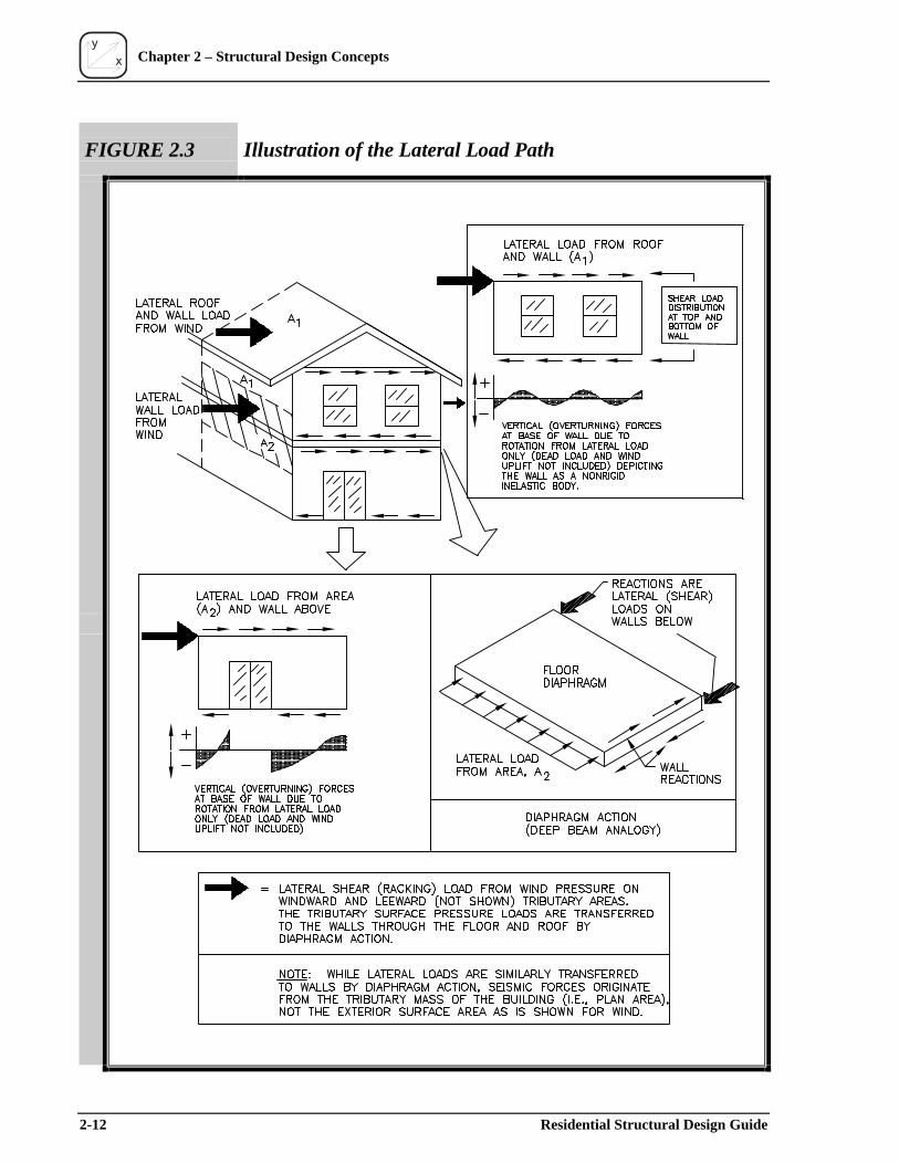
y
x
2-12 Residential Structural Design Guide
Chapter 2 – Structural Design Concepts
FIGURE 2.3 Illustration of the Lateral Load Path

y
x Chapter 2 – Structural Design Concepts
FIGURE 2.4 Illustration of Building Deformation under Lateral Load
Residential Structural Design Guide 2-13

y
x Chapter 2 – Structural Design Concepts
Lateral forces from wind and seismic loads also create overturning forces that cause a “tipping” or “roll-over” effect. When these forces are resisted, a building is prevented from overturning in the direction of the lateral load. On a smaller scale than the whole building, overturning forces are realized at the shear walls of the LFRS such that the shear walls must be restrained from rotating or rocking on their base by proper connection. On an even smaller scale, the forces are realized in the individual shear wall segments between openings in the walls. As shown in Figure 2.3, the overturning forces are not necessarily distributed as might be predicted. The magnitude and distribution of the overturning force can depart significantly from a typical engineering analysis depending on the building or wall configuration.
The overturning force diagrams in Figure 2.3 are based on conventionally built homes constructed without hold-down devices positioned to restrain shear wall segments independently. It should be noted that the effect of dead loads that may offset the overturning force and of wind uplift loads that may increase the overturning force is not necessarily depicted in Figure 2.3’s conceptual plots of overturning forces at the base of the walls. If rigid steel hold-down devices are used in designing the LFRS, the wall begins to behave in a manner similar to a rigid body at the level of individual shear wall segments, particularly when the wall is broken into discrete segments as a result of the configuration of openings in a wall line.
In summary, significant judgment and uncertainty attend the design process for determining building loads and resistance, including definition of the load path and the selection of suitable analytic methods. Designers are often compelled to comply with somewhat arbitrary design provisions or engineering conventions, even when such conventions are questionable or incomplete for particular applications such as a wood-framed home. At the same time, individual designers are not always equipped with sufficient technical information or experience to depart from traditional design conventions. Therefore, this guide is intended to serve as a resource for designers who are considering the use of improved analytic methods when current analytic approaches may be lacking.
2.5 Structural Safety Before addressing the “nuts and bolts” of structural design of single-
family dwellings, it is important to understand the fundamental concept of safety. While safety is generally based on rational principles of risk and probability theory, it is also subject to judgment, particularly the experience and understanding of those who participate in the development of building codes and design standards. For this reason, it is not uncommon to find differences in various code-approved sources for design loads, load combinations, load factors, and other features that affect structural safety and design economy. Despite these inconsistencies, the aim of any design approach is to ensure that the probability of failure (i.e., load exceeding resistance) is acceptably small or, conversely, that the level of safety is sufficiently high.
A common misconception holds that design loads determine the amount of “safety” achieved. It is for this reason that some people tend to focus on design loads to solve real or perceived problems associated with structural performance
2-14 Residential Structural Design Guide

y
x Chapter 2 – Structural Design Concepts
(i.e., safety or property damage). For example, a typical conclusion reached in the aftermath of Hurricane Andrew was that the storm’s wind speed exceeded the design wind speed map value; therefore, the wind map (i.e., design load) was insufficient. In other cases, such as the Northridge Earthquake, reaction to various anecdotal observations resulted in increased safety factors for certain materials (i.e., wood design values were decreased by 25 percent by the City of Los Angeles, California). In reality, several factors affect the level of safety just as several factors determine the level of performance realized by buildings in a single extreme event such as Hurricane Andrew or the Northridge Earthquake (see Chapter 1).
Structural safety is a multifaceted performance goal that integrates all objective and subjective aspects of the design process, including the following major variables:
• determination of characteristic material or assembly strength values based on tested material properties and their variabilities;
• application of a nominal or design load based on a statistical representation of load data and the data’s uncertainty or variability;
• consideration of various uncertainties associated with the design practice (e.g., competency of designers and accuracy of analytic approaches), the construction practice (e.g., quality or workmanship), and durability; and
• selection of a level of safety that considers the above factors and the consequences of exceeding a specified design limit state (i.e., collapse, deformation, or the onset of “unacceptable” damage).
When the above variables are known or logically conceived, there are many ways to achieve a specified level of safety. However, as a practical necessity, the design process has been standardized to provide a reasonably consistent basis for applying the following key elements of the design process:
• characterizing strength properties for various material types (e.g., steel, wood, concrete, masonry, etc.);
• defining nominal design loads and load combinations for crucial inputs into the design process; and
• conveying an acceptable level of safety (i.e., safety margin) that can be easily and consistently applied by designers.
Institutionalized design procedures provide a basis for selecting from the vast array of structural material options available in the construction market. However, the generalizations necessary to address the multitude of design conditions rely on a simplified and standardized format and thus often overlook special aspects of a particular design application.
Residential Structural Design Guide 2-15
y
x Chapter 2 – Structural Design Concepts
While the following sections discuss safety, they are intentionally basic and focus on providing the reader with a conceptual understanding of safety and probability as a fundamental aspect of engineering. Probability concepts are fundamental to modern design formats, such as load and resistance factor design (LRFD), which is also known as reliability-based design or simply strength design. The same concepts are also crucial to understanding the implications of the simple safety factor in traditional allowable stress design (ASD). As with many aspects of engineering, it is important to realize that the treatment of safety is not an exact science but rather depends on the application of sound judgment as much as on the application of complex or sophisticated statistical theories to analyze the many variables in the design process that affect reliability (Gromala et al., 1999). The following references are recommended for further study:
• Probability Concepts in Engineering Planning and Design, Volume I– Basic Principles (Ang and Tang, 1975)
• CRC Structural Engineering Handbook, Chapter 29: Structural Reliability (Chen, 1997)
• Probabilistic Structural Mechanics Handbook: Theory and Industrial Applications (Sundararajan, 1995)
• Uncertainty Analysis, Loads, and Safety in Structural Engineering (Hart, 1982)
• Statistical Models in Engineering (Hahn and Shapiro, 1967)
2.5.1 Nominal Design Loads
Nominal design loads are generally specified on the basis of probability, with the interchangeable terms “return period” and “mean recurrence interval” often used to describe the probability of loads. Either term represents a condition that is predicted to be met or exceeded once on average during the reference time period. For design purposes, loads are generally evaluated in terms of annual extremes (i.e., variability of the largest load experienced in any given one-year period) or maximum life-time values.
The choice of the return period used to define a nominal design load is somewhat arbitrary and must be applied appropriately in the design process. The historical use of safety factors in allowable stress design (ASD) has generally been based on a 50-year return period design load. With the advent of load and resistance factor design (LRFD), the calculation of nominal loads has shifted away from ASD for some load types. For example, earthquake design loads are now based on a 475-year return period event. As a result, a load factor of less than one (i.e., 0.7) must now be used to adjust the earthquake load basis roughly back to a 50-year return period magnitude so that the appropriate level of safety is achieved relative to allowable material strength values used in ASD. This condition is reflected in the design load combinations in Chapter 3.
2-16 Residential Structural Design Guide
y
x Chapter 2 – Structural Design Concepts
The method of determining a design load also differs according to the type of load and the availability of data to evaluate the time-varying nature of loads. The derivation of various nominal loads may be assembled from information and references contained in the ASCE 7 standard (ASCE, 1999). A brief summary is provided here. Design wind loads are based on a probabilistic analysis of wind speed data collected from numerous weather stations across the United States. Given, however, the absence of sufficiently long-term weather data to quantify hurricane risk accurately, wind loads along the hurricane coastline are determined by using a hurricane simulation model that is based on past hurricane tracking records as well as on an examination of the physical characteristics of hurricanes.1
Snow loads are based on snowfall or ground snow depth data and are correlated to roof snow loads through somewhat limited studies. Snow drift loads are conservatively based on drifting on failed roofs and therefore do not necessarily represent the snow-drifting probability that occurs at random in the building population. Earthquake loads are defined from historical ground motion data and conceptualized risk models based on direct or indirect evidence of past earthquake activity. Thus, considerable uncertainty exists in the estimation of seismic hazards, particularly in areas that are believed to have low seismicity (i.e., few events) but the potential for major seismic events. Floor live loads are modeled by using live load surveys of “point-in-time” loading conditions and hypotheses or judgment concerning extreme or maximum life-time loads. In some cases, expert panels decide on appropriate loads or related load characteristics when adequate data are not available.
In summary, the determination of load characteristics is based on historical data, risk modeling, and expert opinion, which, in turn, guide the specification of nominal design loads for general design purposes in both the ASD and LRFD formats. As noted, nominal design loads were usually based on a 50-year return period. Today, however, the calculation of seismic loads and wind loads along the hurricane coastline are based on a return period substantially greater than the 50-year return period used in the past. Thus, traditional perceptions of safety may become somewhat more obscure or even confused with the more recent changes to the design process. It is also important to remember that the return period of the design load is not the only factor determining safety; the selection of safety factors (ASD) and load factors (LRFD) depends on the definition of a nominal design load (i.e., its return period) and the material’s strength characterization to achieve a specified level of safety.
2.5.2 Basic Safety Concepts in Allowable Stress Design
The concept of ASD is demonstrated in a generic design equation or performance function (see Equation 2.5-1). In traditional allowable stress design, it is common to divide the characteristic (i.e., fifth percentile) material strength value by a safety factor of greater than 1 to determine an allowable design strength dependent on a selected limit state (i.e., proportional limit or rupture) and material type, among other factors that involve the judgment of specification-
1The apparent lack of agreement between a few long-term wind speed records beckons a more thorough validation of hurricane risk models and predicted design wind speeds along the Gulf and Atlantic coasts (Rosowsky and Cheng, 1999).
Residential Structural Design Guide 2-17
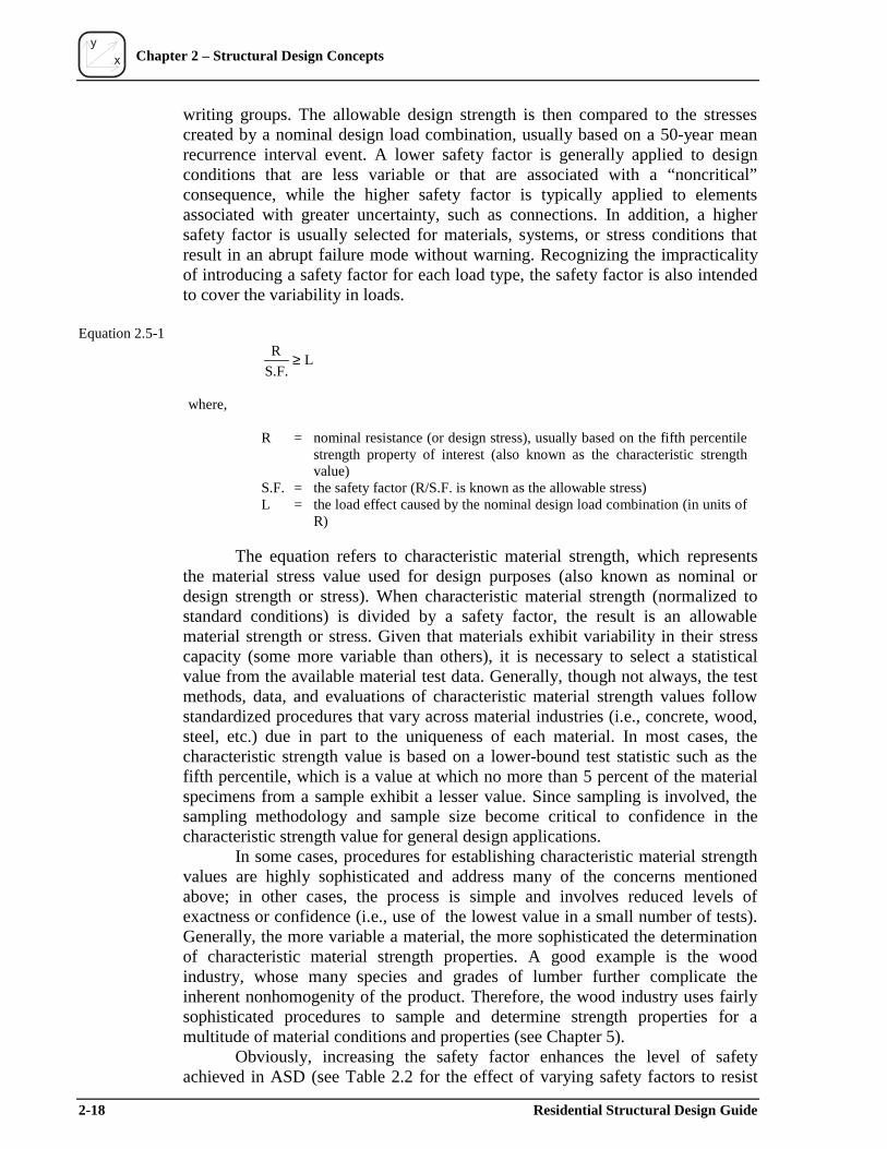
y
x Chapter 2 – Structural Design Concepts
writing groups. The allowable design strength is then compared to the stresses created by a nominal design load combination, usually based on a 50-year mean recurrence interval event. A lower safety factor is generally applied to design conditions that are less variable or that are associated with a “noncritical” consequence, while the higher safety factor is typically applied to elements associated with greater uncertainty, such as connections. In addition, a higher safety factor is usually selected for materials, systems, or stress conditions that result in an abrupt failure mode without warning. Recognizing the impracticality of introducing a safety factor for each load type, the safety factor is also intended to cover the variability in loads.
Equation 2.5-1 R ≥ L
S.F.
where,
R = nominal resistance (or design stress), usually based on the fifth percentile strength property of interest (also known as the characteristic strength value)
S.F. = the safety factor (R/S.F. is known as the allowable stress) L = the load effect caused by the nominal design load combination (in units of
R)
The equation refers to characteristic material strength, which represents the material stress value used for design purposes (also known as nominal or design strength or stress). When characteristic material strength (normalized to standard conditions) is divided by a safety factor, the result is an allowable material strength or stress. Given that materials exhibit variability in their stress capacity (some more variable than others), it is necessary to select a statistical value from the available material test data. Generally, though not always, the test methods, data, and evaluations of characteristic material strength values follow standardized procedures that vary across material industries (i.e., concrete, wood, steel, etc.) due in part to the uniqueness of each material. In most cases, the characteristic strength value is based on a lower-bound test statistic such as the fifth percentile, which is a value at which no more than 5 percent of the material specimens from a sample exhibit a lesser value. Since sampling is involved, the sampling methodology and sample size become critical to confidence in the characteristic strength value for general design applications.
In some cases, procedures for establishing characteristic material strength values are highly sophisticated and address many of the concerns mentioned above; in other cases, the process is simple and involves reduced levels of exactness or confidence (i.e., use of the lowest value in a small number of tests). Generally, the more variable a material, the more sophisticated the determination of characteristic material strength properties. A good example is the wood industry, whose many species and grades of lumber further complicate the inherent nonhomogenity of the product. Therefore, the wood industry uses fairly sophisticated procedures to sample and determine strength properties for a multitude of material conditions and properties (see Chapter 5).
Obviously, increasing the safety factor enhances the level of safety achieved in ASD (see Table 2.2 for the effect of varying safety factors to resist
2-18 Residential Structural Design Guide
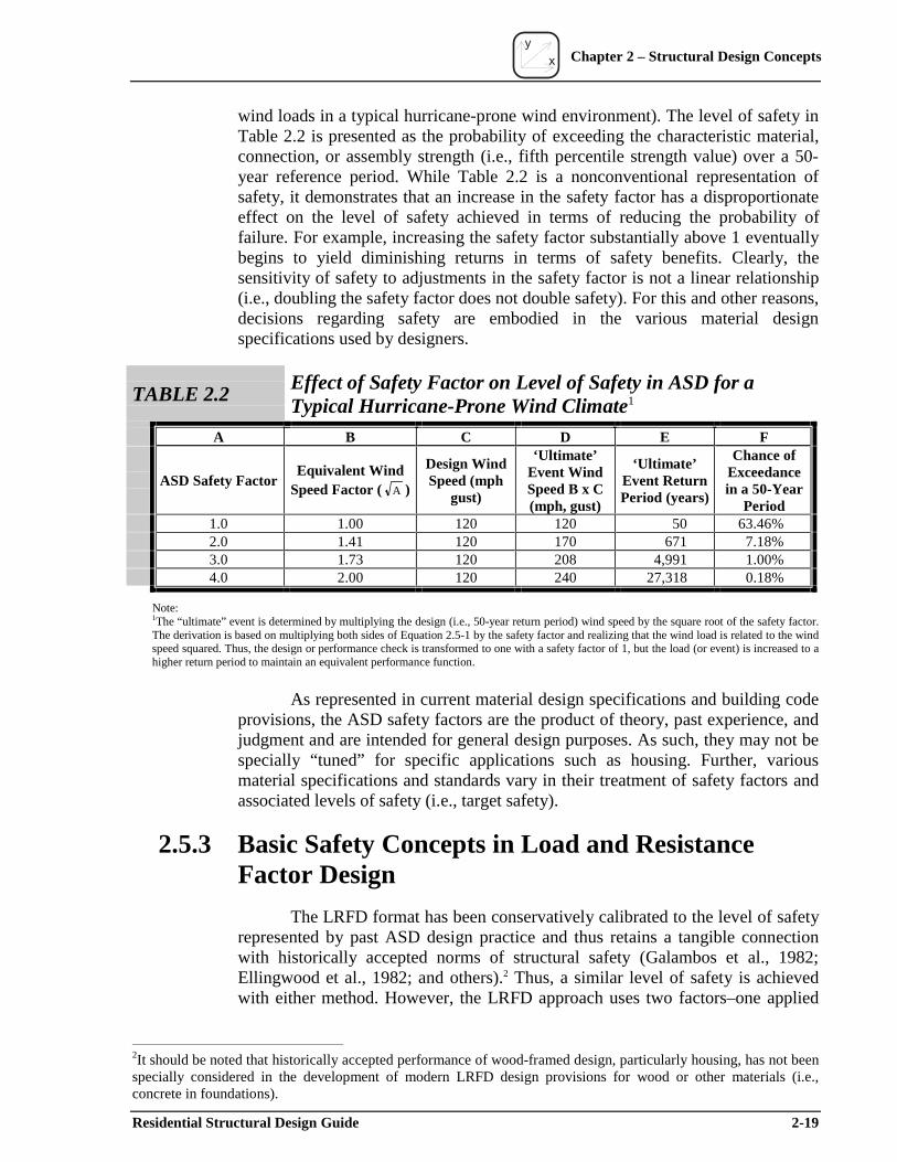
y
x Chapter 2 – Structural Design Concepts
wind loads in a typical hurricane-prone wind environment). The level of safety in Table 2.2 is presented as the probability of exceeding the characteristic material, connection, or assembly strength (i.e., fifth percentile strength value) over a 50-year reference period. While Table 2.2 is a nonconventional representation of safety, it demonstrates that an increase in the safety factor has a disproportionate effect on the level of safety achieved in terms of reducing the probability of failure. For example, increasing the safety factor substantially above 1 eventually begins to yield diminishing returns in terms of safety benefits. Clearly, the sensitivity of safety to adjustments in the safety factor is not a linear relationship (i.e., doubling the safety factor does not double safety). For this and other reasons, decisions regarding safety are embodied in the various material design specifications used by designers.
TABLE 2.2
A
ASD Safety Factor
1.0 2.0 3.0 4.0
Note:
Effect of Safety Factor on Level of Safety in ASD for aTypical Hurricane-Prone Wind Climate1
B
Equivalent Wind Speed Factor ( A )
1.00 1.41 1.73 2.00
C D E F
Design Wind Speed (mph
gust)
‘Ultimate’ Event Wind Speed B x C (mph, gust)
‘Ultimate’ Event Return Period (years)
Chance of Exceedance in a 50-Year
Period 120 120 50 63.46% 120 170 671 7.18% 120 208 4,991 1.00% 120 240 27,318 0.18%
1The “ultimate” event is determined by multiplying the design (i.e., 50-year return period) wind speed by the square root of the safety factor. The derivation is based on multiplying both sides of Equation 2.5-1 by the safety factor and realizing that the wind load is related to the wind speed squared. Thus, the design or performance check is transformed to one with a safety factor of 1, but the load (or event) is increased to a higher return period to maintain an equivalent performance function.
As represented in current material design specifications and building code provisions, the ASD safety factors are the product of theory, past experience, and judgment and are intended for general design purposes. As such, they may not be specially “tuned” for specific applications such as housing. Further, various material specifications and standards vary in their treatment of safety factors and associated levels of safety (i.e., target safety).
2.5.3 Basic Safety Concepts in Load and Resistance Factor Design
The LRFD format has been conservatively calibrated to the level of safety represented by past ASD design practice and thus retains a tangible connection with historically accepted norms of structural safety (Galambos et al., 1982; Ellingwood et al., 1982; and others).2 Thus, a similar level of safety is achieved with either method. However, the LRFD approach uses two factors–one applied
2It should be noted that historically accepted performance of wood-framed design, particularly housing, has not been specially considered in the development of modern LRFD design provisions for wood or other materials (i.e., concrete in foundations).
Residential Structural Design Guide 2-19
y
x Chapter 2 – Structural Design Concepts
to the load and one applied to the resistance or strength property–that permits a more consistent treatment of safety across a broader range of design conditions.
Equation 2.5-2 shows conceptually the LRFD design format (i.e., performance function) and compares a factored characteristic resistance value with a factored nominal load. Thus, for a given hazard condition and given material, and similar to the outcome described in the previous section on ASD, increasing the load factor and/or decreasing the resistance factor has the effect of increasing the level of safety. Figure 2.5 depicts the variable nature of building loads and resistance and the safety margin relative to design loads and nominal resistance.
Equation 2.5-2 φ R ≥ ∑ γL
where,
φ = resistance factor (phi)R = nominal resistance or design stress usually based on the fifth percentile
strength property of interest (also known as the characteristic strength value) γ = load factor for each load in a given load combination (gamma) L = the stress created by each load in a nominal design load combination (in units
of R)
A resistance factor is applied to a characteristic material strength value to account for variability in material strength properties. The resistance factor generally ranges from 0.5 to 0.9, with the lower values applicable to those strength properties that have greater variability or that are associated with an abrupt failure that gives little warning. The resistance factor also depends on the selected characterization of the nominal or characteristic strength value for design purposes (i.e., average, lower fifth percentile, lowest value of a limited number of tests, etc.).
A load factor is individually applied to each load in a nominal design load combination to account for the variability and nature of the hazard or combined hazards. It also depends on the selected characterization of the nominal load for design purposes (i.e., 50-year return period, 475-year return period, or others). In addition, the load factors proportion the loads relative to each other in a combination of loads (i.e., account for independence or correlation between loads and their likely “point-in-time” values when one load assumes a maximum value). Thus, the load factor for a primary load in a load combination may range from 1 to 1.6 in LRFD. For other transient loads in a combination, the factors are generally much less than 1. In this manner, the level of safety for a given material and nominal design load is determined by the net effect of factors–one on the resistance side of the design equation and the others on the load side. For ASD, the factors and their purpose are embodied in one simple factor–the safety factor.
2-20 Residential Structural Design Guide
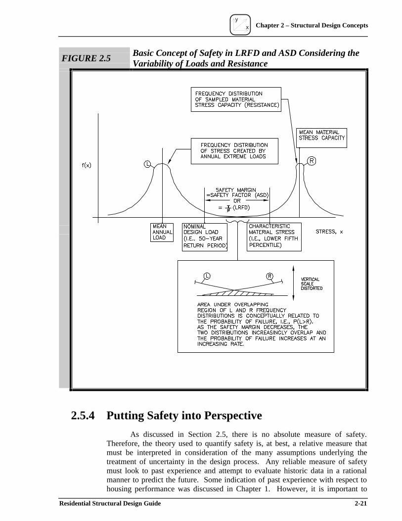
y
x Chapter 2 – Structural Design Concepts
FIGURE 2.5Basic Concept of Safety in LRFD and ASD Considering the Variability of Loads and Resistance
2.5.4 Putting Safety into Perspective
As discussed in Section 2.5, there is no absolute measure of safety. Therefore, the theory used to quantify safety is, at best, a relative measure that must be interpreted in consideration of the many assumptions underlying the treatment of uncertainty in the design process. Any reliable measure of safety must look to past experience and attempt to evaluate historic data in a rational manner to predict the future. Some indication of past experience with respect to housing performance was discussed in Chapter 1. However, it is important to
Residential Structural Design Guide 2-21
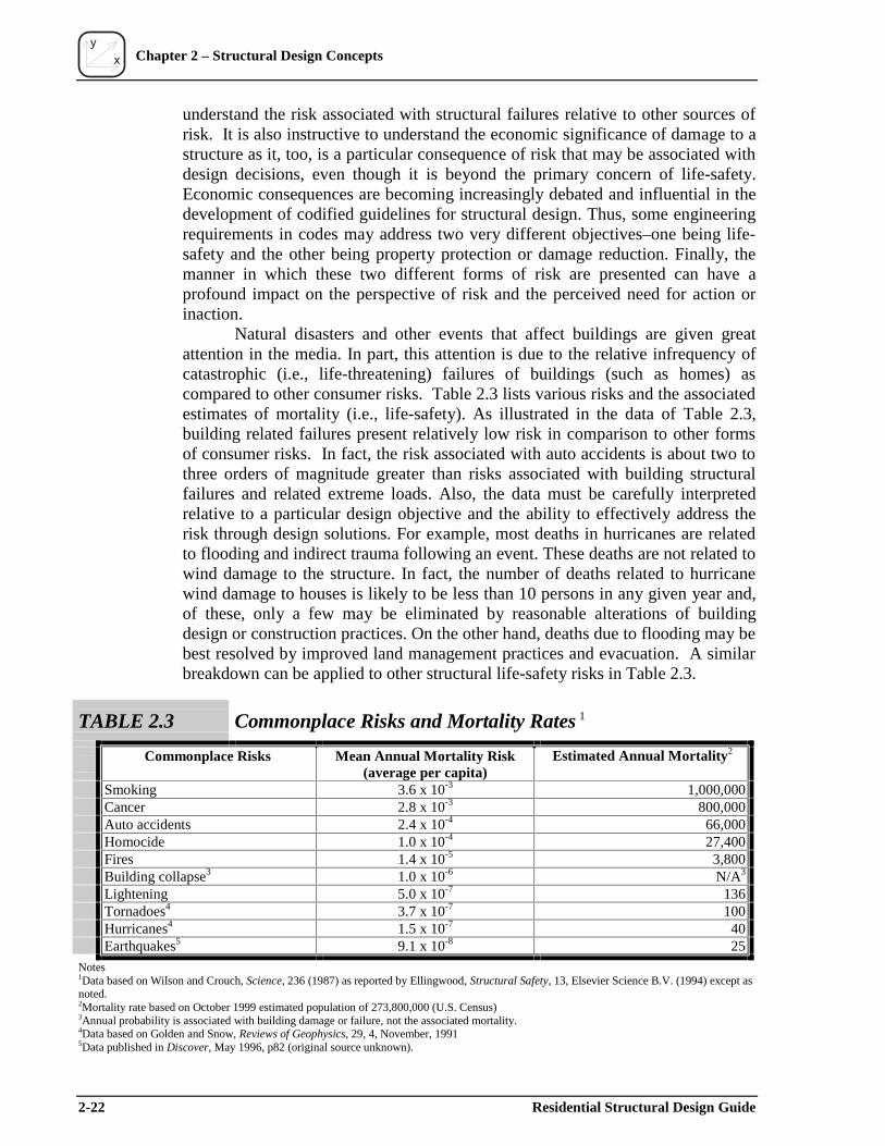
y
x Chapter 2 – Structural Design Concepts
understand the risk associated with structural failures relative to other sources of risk. It is also instructive to understand the economic significance of damage to a structure as it, too, is a particular consequence of risk that may be associated with design decisions, even though it is beyond the primary concern of life-safety. Economic consequences are becoming increasingly debated and influential in the development of codified guidelines for structural design. Thus, some engineering requirements in codes may address two very different objectives–one being life-safety and the other being property protection or damage reduction. Finally, the manner in which these two different forms of risk are presented can have a profound impact on the perspective of risk and the perceived need for action or inaction.
Natural disasters and other events that affect buildings are given great attention in the media. In part, this attention is due to the relative infrequency of catastrophic (i.e., life-threatening) failures of buildings (such as homes) as compared to other consumer risks. Table 2.3 lists various risks and the associated estimates of mortality (i.e., life-safety). As illustrated in the data of Table 2.3, building related failures present relatively low risk in comparison to other forms of consumer risks. In fact, the risk associated with auto accidents is about two to three orders of magnitude greater than risks associated with building structural failures and related extreme loads. Also, the data must be carefully interpreted relative to a particular design objective and the ability to effectively address the risk through design solutions. For example, most deaths in hurricanes are related to flooding and indirect trauma following an event. These deaths are not related to wind damage to the structure. In fact, the number of deaths related to hurricane wind damage to houses is likely to be less than 10 persons in any given year and, of these, only a few may be eliminated by reasonable alterations of building design or construction practices. On the other hand, deaths due to flooding may be best resolved by improved land management practices and evacuation. A similar breakdown can be applied to other structural life-safety risks in Table 2.3.
TABLE 2.3 Commonplace Risks and Mortality Rates 1
Commonplac ks Rise Mean Annual Mortality Risk Estimated Annual Mortality2
(average per capita) SmokingCancerAuto accidentsHomocideFiresBuilding collapse3
LighteningTornadoes4
Hurricanes4
Earthquakes5
3.6 x 10⁻³ 1,000,000 2.8 x 10⁻³ 800,000 2.4 x 10⁻⁴ 66,000 1.0 x 10⁻⁴ 27,400 1.4 x 10⁻⁵ 3,800 1.0 x 10⁻⁶ N/A3
5.0 x 10⁻⁷ 136 3.7 x 10⁻⁷ 100 1.5 x 10⁻⁷ 40 9.1 x 10⁻⁸ 25
Notes1Data based on Wilson and Crouch, Science, 236 (1987) as reported by Ellingwood, Structural Safety, 13, Elsevier Science B.V. (1994) except asnoted.2Mortality rate based on October 1999 estimated population of 273,800,000 (U.S. Census)3Annual probability is associated with building damage or failure, not the associated mortality.4Data based on Golden and Snow, Reviews of Geophysics, 29, 4, November, 19915Data published in Discover, May 1996, p82 (original source unknown).
2-22 Residential Structural Design Guide
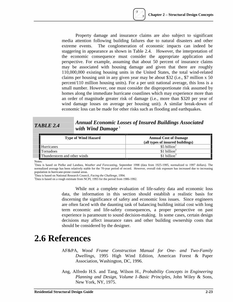
y
x Chapter 2 – Structural Design Concepts
Property damage and insurance claims are also subject to significant media attention following building failures due to natural disasters and other extreme events. The conglomeration of economic impacts can indeed be staggering in appearance as shown in Table 2.4. However, the interpretation of the economic consequence must consider the appropriate application and perspective. For example, assuming that about 50 percent of insurance claims may be associated with housing damage and given that there are roughly 110,000,000 existing housing units in the United States, the total wind-related claims per housing unit in any given year may be about $32 (i.e., $7 million x 50 percent/110 million housing units). For a per unit national average, this loss is a small number. However, one must consider the disproportionate risk assumed by homes along the immediate hurricane coastlines which may experience more than an order of magnitude greater risk of damage (i.e., more than $320 per year of wind damage losses on average per housing unit). A similar break-down of economic loss can be made for other risks such as flooding and earthquakes.
TABLE 2.4Annual Economic Losses of Insured Buildings Associated with Wind Damage 1
Type f Wind Hazard
Hurricanes Tornadoes Thunderstorm and other winds
o Annual Cost of Damage(all types of insured buildings)
$5 billion1
$1 billion2
$1 billion3
Notes:1Data is based on Pielke and Landsea, Weather and Forecasting, September 1998 (data from 1925-1995, normalized to 1997 dollars). Thenormalized average has been relatively stable for the 70-year period of record. However, overall risk exposure has increased due to increasingpopulation in hurricane-prone coastal areas.2Data is based on National Research Council, Facing the Challenge, 1994.3Data is based on a rough estimate from NCPI, 1993 for the period from 1986-1992.
While not a complete evaluation of life-safety data and economic loss data, the information in this section should establish a realistic basis for discerning the significance of safety and economic loss issues. Since engineers are often faced with the daunting task of balancing building initial cost with long term economic and life-safety consequences, a proper perspective on past experience is paramount to sound decision-making. In some cases, certain design decisions may affect insurance rates and other building ownership costs that should be considered by the designer.
2.6 References AF&PA, Wood Frame Construction Manual for One- and Two-Family
Dwellings, 1995 High Wind Edition, American Forest & Paper Association, Washington, DC, 1996.
Ang, Alfredo H.S. and Tang, Wilson H., Probability Concepts in Engineering Planning and Design, Volume I–Basic Principles, John Wiley & Sons, New York, NY, 1975.
Residential Structural Design Guide 2-23
y
x Chapter 2 – Structural Design Concepts
ASCE, Minimum Building Loads for Buildings and Other Structures (ASCE 7-95), American Society of Civil Engineers, Reston, VA, 1996.
ASCE, Minimum Building Loads for Buildings and Other Structures (ASCE 7-98), American Society of Civil Engineers, Reston, VA, 1999.
Chalk, P. and Corotis, R., “Probability Model for Design Live Loads,” Journal of the Structural Division, American Society of Civil Engineers, Reston, VA, October 1980.
Chen, W.F., Structural Engineering Handbook, Chapter 29: Structural Reliability, CRC Press, 1997.
Ellingwood, B. et al., “Probability Based Load Criteria: Load Factors and Load Combinations,” Journal of the Structural Division, Vol. 108 No. ST5, American Society of Civil Engineers, May 1982, 978-997.
Galambos, T.V. et al., “Probability Based Load Criteria: Assessment of Current Design Practice,” Journal of the Structural Division, Vol. 108 No. ST5, American Society of Civil Engineers, May 1982, 959-977.
Gromala, D.S., Douglas, B.K., Rosowsky, D.V., and Sharp, D.J., "Why Is Reliability Analysis So Unreliable?," Proceedings of Pacific Timber Engineering Conference (Forest Research Bulletin 212), Rotura, New Zealand, March 14–18, 1999.
Hahn, G.J., and Shapiro, S.S., Statistical Models in Engineering, John Wiley & Sons, New York, NY, 1967.
Hart, Gary C., Uncertainty Analysis, Loads, and Safety in Structural Engineering, Prentice-Hall, Inc., Englewood Cliffs, NJ, 1982.
Hurst, Homer T., The Wood-Frame House as a Structural Unit, Technical Report No. 5, National Forest Products Association, Washington, DC, 1965.
ICBO, Uniform Building Code (UBC), International Conference of Building Officials (ICBO), Whittier, CA, 1997.
ICC, International Residential Code for One- and Two-Family Dwellings–2000 Edition, International Code Council, Falls Church, VA, 1999 (final draft).
NBS, Strength of Houses: Application of Engineering Principles to Structural Design, Building Materials and Structures Report 109, U.S. Department of Commerce, National Bureau of Standards (GPO: Washington, DC), April 1, 1948.
2-24 Residential Structural Design Guide

y
x Chapter 2 – Structural Design Concepts
Rosowsky, D.V. and Cheng, N., "Reliability of Light-Frame Roofs in High-Wind Regions. I: Wind Loads," Journal of Structural Engineering, Vol. 125 No. 7, American Society of Civil Engineers, Reston, VA, July 1999, 725-730.
SBCCI, Standard for Hurricane Resistant Residential Construction (SSTD 10-99), Southern Building Code Congress International, Birmingham, AL, 1999.
Sundararajan, C., Probabilistic Structural Mechanics Handbook: Theory and Industrial Applications, Chapman & Hall, New York, NY, 1995.
TPI, National Design Standard for Metal Plate Connected Wood Trusses, Truss Plate Institute (TPI), Madison, WI, 1996.
WTCA, Metal Plate Connected Wood Truss Handbook, Second Edition, prepared by Edward E. Callahan for the Wood Truss Council of America, Madison, WI, 1998.
Residential Structural Design Guide 2-25
y
x Chapter 2 – Structural Design Concepts
2-26 Residential Structural Design Guide