residential/commercial generator sets · residential/commercial generator sets models: 14/20res...
TRANSCRIPT

Residential/Commercial Generator Sets
Models:
14/20RES
14/20RESL
Controller:
RDC Residential Digital ControllerDC Digital Controller
TP-6733 5/10
Installation
Engine exhaust from this product contains chemicals
known to the State of California to cause cancer, birth
defects, or other reproductive harm.
WARNING
California Proposition 65
Product Identification Information
Generator Set Identification Numbers
Record the product identification numbers from the
generator set nameplate(s).
Model Designation
Specification Number
Serial Number
Accessory Number Accessory Description
Engine Identification
Record the product identification information from the
engine nameplate.
Manufacturer
Model Designation
Serial Number
Controller Identification
Record the controller description from the generator set
operation manual, spec sheet, or sales invoice.
Controller Description

Table of Contents
TP-6733 5/10 Table of Contents 3
Product Identification Information 2. . . . . . . . . . . . . . . . . . . . . . . . . . . . . . . . . . . . . . . . . . . . . . . . . . . . . . . . . . . .
Safety Precautions and Instructions 5. . . . . . . . . . . . . . . . . . . . . . . . . . . . . . . . . . . . . . . . . . . . . . . . . . . . . . . .
Introduction 9. . . . . . . . . . . . . . . . . . . . . . . . . . . . . . . . . . . . . . . . . . . . . . . . . . . . . . . . . . . . . . . . . . . . . . . . . . . . . . .
Startup and Registration 9. . . . . . . . . . . . . . . . . . . . . . . . . . . . . . . . . . . . . . . . . . . . . . . . . . . . .
Service Assistance 10. . . . . . . . . . . . . . . . . . . . . . . . . . . . . . . . . . . . . . . . . . . . . . . . . . . . . . . . . . . . . . . . . . . . . . . .
Section 1 Installation 11. . . . . . . . . . . . . . . . . . . . . . . . . . . . . . . . . . . . . . . . . . . . . . . . . . . . . . . . . . . . . . . . . . . . . .
1.1 General 11. . . . . . . . . . . . . . . . . . . . . . . . . . . . . . . . . . . . . . . . . . . . . . . . . . . . . . . . . . . . . .
1.2 Lifting 11. . . . . . . . . . . . . . . . . . . . . . . . . . . . . . . . . . . . . . . . . . . . . . . . . . . . . . . . . . . . . . .
1.3 Generator Set Inspection 11. . . . . . . . . . . . . . . . . . . . . . . . . . . . . . . . . . . . . . . . . . . . . . .
1.4 Location and Mounting 11. . . . . . . . . . . . . . . . . . . . . . . . . . . . . . . . . . . . . . . . . . . . . . . . .
1.4.1 Exhaust Requirements 11. . . . . . . . . . . . . . . . . . . . . . . . . . . . . . . . . . . . . . . . .
1.4.2 Mounting Area 12. . . . . . . . . . . . . . . . . . . . . . . . . . . . . . . . . . . . . . . . . . . . . . . .
1.5 Fuel Requirements 17. . . . . . . . . . . . . . . . . . . . . . . . . . . . . . . . . . . . . . . . . . . . . . . . . . . .
1.5.1 Fuel Supply 17. . . . . . . . . . . . . . . . . . . . . . . . . . . . . . . . . . . . . . . . . . . . . . . . . .
1.5.2 Fuel Pipe Size 17. . . . . . . . . . . . . . . . . . . . . . . . . . . . . . . . . . . . . . . . . . . . . . . .
1.6 Fuel Conversion 18. . . . . . . . . . . . . . . . . . . . . . . . . . . . . . . . . . . . . . . . . . . . . . . . . . . . . .
1.6.1 Fuel Conversion, 14RES/RESL 19. . . . . . . . . . . . . . . . . . . . . . . . . . . . . . . . .
1.6.2 Fuel Conversion, 20RES/RESL 20. . . . . . . . . . . . . . . . . . . . . . . . . . . . . . . . .
1.7 Electrical Connections 21. . . . . . . . . . . . . . . . . . . . . . . . . . . . . . . . . . . . . . . . . . . . . . . . .
1.7.1 Power for the Battery Charger 21. . . . . . . . . . . . . . . . . . . . . . . . . . . . . . . . . . .
1.7.2 Field-Connection Terminal Block 22. . . . . . . . . . . . . . . . . . . . . . . . . . . . . . . .
1.7.3 Grounding 23. . . . . . . . . . . . . . . . . . . . . . . . . . . . . . . . . . . . . . . . . . . . . . . . . . . .
1.7.4 Battery Charger 23. . . . . . . . . . . . . . . . . . . . . . . . . . . . . . . . . . . . . . . . . . . . . . .
1.8 Battery 24. . . . . . . . . . . . . . . . . . . . . . . . . . . . . . . . . . . . . . . . . . . . . . . . . . . . . . . . . . . . . . .
1.9 Carburetor Heater 25. . . . . . . . . . . . . . . . . . . . . . . . . . . . . . . . . . . . . . . . . . . . . . . . . . . . .
1.10 Prestart Installation Check 27. . . . . . . . . . . . . . . . . . . . . . . . . . . . . . . . . . . . . . . . . . . . . .
1.11 Controller Configuration and Firmware Updates 27. . . . . . . . . . . . . . . . . . . . . . . . . . .
1.11.1 Firmware Version and Update 28. . . . . . . . . . . . . . . . . . . . . . . . . . . . . . . . . . .
1.11.2 System Parameters 28. . . . . . . . . . . . . . . . . . . . . . . . . . . . . . . . . . . . . . . . . . . .
1.11.3 RDC Controller Configuration 28. . . . . . . . . . . . . . . . . . . . . . . . . . . . . . . . . . .
1.12 Performance Adjustments, RDC Controller 30. . . . . . . . . . . . . . . . . . . . . . . . . . . . . . .
1.12.1 Voltage Adjustment 30. . . . . . . . . . . . . . . . . . . . . . . . . . . . . . . . . . . . . . . . . . . .
1.12.2 Frequency Adjustment 31. . . . . . . . . . . . . . . . . . . . . . . . . . . . . . . . . . . . . . . . .
Section 2 Wiring Diagrams 33. . . . . . . . . . . . . . . . . . . . . . . . . . . . . . . . . . . . . . . . . . . . . . . . . . . . . . . . . . . . . . . .
Appendix A Abbreviations 37. . . . . . . . . . . . . . . . . . . . . . . . . . . . . . . . . . . . . . . . . . . . . . . . . . . . . . . . . . . . . . . . . .

TP-6733 5/104
Notes
TP-6733 5/10 5Safety Precautions and Instructions
Safety Precautions and Instructions
IMPORTANT SAFETY INSTRUCTIONS.
Electromechanical equipment,including generator sets, transferswitches,switchgear, andaccessories,
can cause bodily harm and poselife-threatening danger whenimproperly installed, operated, ormaintained. To prevent accidents beaware of potential dangers and actsafely. Read and follow all safety
precautions and instructions. SAVETHESE INSTRUCTIONS.
Thismanual hasseveral typesofsafetyprecautions and instructions: Danger,Warning, Caution, and Notice.
DANGER
Danger indicates the presence of ahazard that will cause severe
personal injury,death, orsubstantialproperty damage.
WARNING
Warning indicates the presence of ahazard that can cause severe
personal injury,death,orsubstantialproperty damage.
CAUTION
Caution indicates the presence of ahazard that will or can cause minor
personal injury or property damage.
NOTICE
Notice communicates installation,operation, or maintenance informationthat is safety related but not hazardrelated.
Safety decals affixed to the equipment
in prominent places alert the operatoror service technician to potentialhazards and explain how to act safely.The decals are shown throughout thispublication to improve operatorrecognition. Replace missing or
damaged decals.
Accidental Starting
Accidental starting.Can cause severe injury or death.
Disconnect the battery cables beforeworking on the generator set.
Remove the negative (--) lead firstwhen disconnecting the battery.Reconnect the negative (--) lead lastwhen reconnecting the battery.
WARNING
Disabling the generator set.Accidental starting can causesevere injury or death. Beforeworking on the generator set orconnected equipment, disable the
generator set as follows: (1) Move thegenerator set master switch to theOFFposition. (2) Disconnect the power tothe battery charger. (3) Remove thebattery cables, negative (--) lead first.Reconnect the negative (--) lead last
when reconnecting the battery. Followthese precautions to prevent starting ofthe generator set by an automatictransfer switch, remote start/stopswitch, or engine start command fromaremote computer.
Battery
Sulfuric acid in batteries.Can cause severe injury or death.
Wear protective goggles andclothing. Battery acid may cause
blindness and burn skin.
WARNING
Explosion.Can cause severe injury or death.Relays in the battery chargercause arcs or sparks.
Locate the battery in awell-ventilatedarea. Isolate thebattery charger fromexplosive fumes.
WARNING
Battery electrolyte is a dilutedsulfuric acid. Batteryacidcancausesevere injury or death. Battery acid
can cause blindness and burn skin.Always wear splashproof safetygoggles, rubber gloves, and bootswhen servicing the battery. Do notopen a sealed battery or mutilate thebattery case. If battery acid splashes in
the eyes or on the skin, immediatelyflush the affected area for 15 minuteswith large quantities of clean water.Seek immediatemedical aid in thecaseof eye contact. Never add acid to a
battery after placing the battery inservice, as thismay result inhazardousspattering of battery acid.
Battery acid cleanup. Battery acidcan cause severe injury or death.Battery acid is electrically conductive
and corrosive. Add 500 g (1 lb.) ofbicarbonate of soda (baking soda) to acontainer with 4 L (1 gal.) of water andmix the neutralizing solution. Pour theneutralizing solution on the spilledbattery acid and continue to add the
neutralizing solution to the spilledbattery acid until all evidence of achemical reaction (foaming) hasceased. Flush the resulting liquid withwater and dry the area.
TP-6733 5/106 Safety Precautions and Instructions
Battery gases. Explosion can causesevere injury or death. Battery gasescan cause an explosion. Do not smokeorpermit flamesor sparks to occurnear
a battery at any time, particularly whenit is charging. Do not dispose of abattery in a fire. To prevent burns andsparks that could cause an explosion,avoid touching the battery terminalswith tools or other metal objects.
Removeall jewelrybefore servicing theequipment. Discharge static electricityfrom your body before touchingbatteries by first touching a groundedmetal surfaceaway from thebattery. Toavoid sparks, do not disturb the battery
charger connections while the batteryis charging. Always turn the batterycharger off before disconnecting thebattery connections. Ventilate thecompartments containing batteries toprevent accumulation of explosive
gases.
Battery short circuits. Explosioncan cause severe injury or death.Short circuits can cause bodily injuryand/or equipment damage.Disconnect the battery before
generator set installation ormaintenance. Remove all jewelrybefore servicing the equipment. Usetools with insulated handles. Removethe negative (--) lead first when
disconnecting the battery. Reconnectthe negative (--) lead last whenreconnecting the battery. Neverconnect the negative (--) battery cableto the positive (+) connection terminalof the starter solenoid. Do not test the
battery condition by shorting theterminals together.
Engine Backfire/FlashFire
Fire.Can cause severe injury or death.
Do not smoke or permit flames orsparks near fuels or the fuel system.
WARNING
Servicing the air cleaner. A suddenbackfire can cause severe injury ordeath. Do not operate the generatorset with the air cleaner removed.
Servicing the fuel system. A flashfirecancausesevere injuryordeath.Do not smoke or permit flames orsparks near the carburetor, fuel line,fuel filter, fuel pump, or other potentialsources of spilled fuels or fuel vapors.
Catch fuels in an approved containerwhen removing the fuel line orcarburetor.
Combustible materials. A fire cancause severe injury or death.
Generator set engine fuels and fuelvapors are flammable and explosive.Handle these materials carefully tominimize the risk of fire or explosion.Equip the compartment or nearby areawith a fully charged fire extinguisher.
Select a fire extinguisher rated ABC orBC for electrical fires or asrecommended by the local fire code oran authorized agency. Train allpersonnel on fire extinguisheroperation and fire prevention
procedures.
Exhaust System
Carbon monoxide.Can cause severe nausea,fainting, or death.
The exhaust system must be
leakproof and routinely inspected.
WARNING
Generator set operation. Carbonmonoxidecancauseseverenausea,fainting, or death. Carbon monoxideis an odorless, colorless, tasteless,
nonirritating gas that can cause death ifinhaled for even a short time. Avoidbreathingexhaust fumeswhenworkingon or near the generator set. Neveroperate the generator set inside abuilding. Never operate the generator
set where exhaust gas could seepinside or be drawn into a potentiallyoccupied building throughwindows, airintake vents, or other openings.
Carbon monoxide detectors.
Carbonmonoxide can cause severenausea, fainting, or death. Installcarbon monoxide detectors on eachlevel of any building adjacent to thegenerator set. Locate the detectors toadequately warn the building’s
occupants of the presence of carbonmonoxide. Keep the detectorsoperational at all times. Periodicallytest and replace the carbon monoxidedetectors according to themanufacturer’s instructions.
Carbon monoxide symptoms.Carbonmonoxide can cause severenausea, fainting, or death. Carbonmonoxide isapoisonousgaspresent inexhaust gases. Carbonmonoxide isanodorless, colorless, tasteless,
nonirritating gas that can cause death ifinhaled for even a short time. Carbonmonoxidepoisoningsymptoms includebut are not limited to the following:
Light-headedness, dizziness Physical fatigue, weakness in
joints and muscles Sleepiness, mental fatigue,
inability to concentrateor speak clearly, blurred vision
Stomachache, vomiting, nauseaIf experiencing any of these symptoms
and carbon monoxide poisoning ispossible, seek fresh air immediatelyand remain active. Do not sit, lie down,or fall asleep. Alert others to thepossibility of carbon monoxidepoisoning. Seek medical attention if
the condition of affected persons doesnot improvewithinminutes of breathingfresh air.
TP-6733 5/10 7Safety Precautions and Instructions
Fuel System
Explosive fuel vapors.Can cause severe injury or death.
Use extreme care when handling,storing, and using fuels.
WARNING
The fuel system. Explosive fuelvapors can cause severe injury ordeath. Vaporized fuels are highlyexplosive. Use extreme care whenhandling and storing fuels. Store fuels
in a well-ventilated area away fromspark-producing equipment and out ofthe reach of children. Never add fuel tothe tank while the engine is runningbecause spilled fuel may ignite oncontact with hot parts or from sparks.
Do not smoke or permit flames orsparks to occur near sources of spilledfuel or fuel vapors. Keep the fuel linesand connections tight and in goodcondition. Do not replace flexible fuellines with rigid lines. Use flexible
sections to avoid fuel line breakagecausedbyvibration. Donotoperate thegenerator set in the presence of fuelleaks, fuel accumulation, or sparks.Repair fuel systems before resuming
generator set operation.
Gas fuel leaks. Explosive fuelvapors can cause severe injury ordeath. Fuel leakage can cause anexplosion. Check the LP vapor gas ornatural gas fuel system for leakage by
using a soap and water solution withthe fuel system test pressurized to6--8 ounces per square inch(10--14 inches water column). Do notuse a soap solution containing eitherammonia or chlorine because both
preventbubble formation. Asuccessfultest depends on the ability of thesolution to bubble.
Hazardous Noise
Hazardous noise.
Can cause hearing loss.
Never operate the generator set
without a muffler or with a faulty
exhaust system.
CAUTION
Engine noise. Hazardous noise cancause hearing loss. Generator setsnot equipped with sound enclosurescan produce noise levels greater than105 dBA. Prolongedexposure tonoise
levels greater than 85 dBA can causepermanent hearing loss. Wear hearingprotection when near an operatinggenerator set.
Hazardous Voltage/Moving Parts
Hazardous voltage.Can cause severe injury or death.
Operate the generator set only whenall guards and electrical enclosures
are in place.
Moving parts.
WARNING
Hazardous voltage.
Backfeed to the utility system can
cause property damage, severe
injury, or death.
If the generator set is used for
standby power, install an automatic
transfer switch to prevent inadvertent
interconnection of standby and
normal sources of supply.
WARNING
Welding the generator set.Can cause severe electricalequipment damage.
Never weld components of the
generator set without firstdisconnecting the battery, controllerwiringharness, andengineelectroniccontrol module (ECM).
CAUTION
Grounding electrical equipment.Hazardous voltage can causesevere injury or death. Electrocutionis possible whenever electricity ispresent. Ensure you comply with all
applicable codes and standards.Electrically ground the generator set,transfer switch, and related equipmentandelectrical circuits. Turnoff themaincircuit breakers of all power sources
before servicing the equipment. Nevercontact electrical leads or applianceswhen standing in water or on wetground because these conditionsincrease the risk of electrocution.
Welding on the generator set. Can
cause severe electrical equipmentdamage. Before welding on thegenerator set perform the followingsteps: (1) Remove the battery cables,negative (--) lead first. (2) Disconnectall engine electronic control module
(ECM) connectors. (3) Disconnect allgenerator set controller and voltageregulator circuit board connectors.(4) Disconnect the engine battery-charging alternator connections.(5) Attach the weld ground connection
close to the weld location.
Connecting the battery and thebattery charger. Hazardous voltagecan cause severe injury or death.Reconnect the battery correctly,positive to positive and negative to
negative, to avoid electrical shock anddamage to the battery charger andbattery(ies). Have a qualifiedelectrician install the battery(ies).

TP-6733 5/108 Safety Precautions and Instructions
Short circuits. Hazardousvoltage/current can cause severeinjury or death. Short circuits cancause bodily injury and/or equipment
damage. Do not contact electricalconnections with tools or jewelry whilemaking adjustments or repairs.Removeall jewelrybefore servicing theequipment.
Electrical backfeed to the utility.
Hazardous backfeed voltage cancause severe injury or death. Installa transfer switch in standby powerinstallations to prevent the connectionof standby and other sources of power.
Electrical backfeed into a utilityelectrical system can cause severeinjury or death to utility personnelworking on power lines.
Heavy Equipment
Unbalanced weight.
Improper lifting can cause severe
injury or death and equipment
damage.
Do not use lifting eyes.
Lift the generator set using lifting bars
inserted through the lifting holes on
the skid.
WARNING
Hot Parts
Hot engine and exhaust system.Can cause severe injury or death.
Do not work on the generator set untilit cools.
WARNING
Servicing the exhaust system. Hotparts can cause severe injury ordeath. Do not touch hot engine parts.The engine and exhaust systemcomponents become extremely hot
during operation.
Servicing the engine heater. Hotparts can cause minor personalinjuryorpropertydamage. Install theheater before connecting it to power.
Operating theheater before installationcan cause burns and componentdamage. Disconnect power to theheater and allow it to cool beforeservicing the heater or nearby parts.
Notice
NOTICE
Canadian installations only. Forstandby service connect the output ofthe generator set to a suitably ratedtransfer switch in accordance withCanadian Electrical Code, Part 1.

TP-6733 5/10 9
Introduction
This manual provides installation instructions for
Residential/Commercial model 14/20RES or
14/20RESL generator sets. See Figure 1. Refer to
TP-6734, OperationManual, for generator set operation
and maintenance instructions.
The generator set is approved for use in stationary
applications in locations served by a reliable utility
power source.
Have an authorized distributor/dealer install the
generator set outdoors according to the instructions in
this manual. The generator set installation must comply
with the National Electrical Code (NEC) and local code
requirements. Do not install this generator set indoors.
Information in this publication represents data available
at the time of print. Kohler Co. reserves the right to
change this publication and the products represented
without notice and without any obligation or liability
whatsoever.
Read this manual and carefully follow all procedures
and safety precautions to ensure proper equipment
operation and to avoid bodily injury. Read and follow the
Safety Precautions and Instructions section at the
beginning of this manual.
zaa28533
Figure 1 14/20RES/RESL Generator Set
Startup and Registration
When the generator set is installed, complete the
startup and installation checklists supplied with the
startup notification form. Complete and sign the startup
notification form and register the unit using the Kohler
online Warranty Processing System.

TP-6733 5/1010
Service Assistance
For professional advice on generator set power
requirements and conscientious service, please contact
your nearest Kohler distributor or dealer.
Consult the Yellow Pages under the heading
Generators—Electric.
Visit the Kohler Power Systems website at
KohlerPower.com.
Look at the labels and stickers on your Kohler product
or review the appropriate literature or documents
included with the product.
Call toll free in the US and Canada 1-800-544-2444.
Outside the US andCanada, call the nearest regional
office.
Headquarters Europe, Middle East, Africa
(EMEA)
Kohler Power Systems
3 rue de Brennus
93200 Saint Denis
France
Phone: (33) 1 49 178300
Fax: (33) 1 49 178301
Asia Pacific
Power Systems Asia Pacific Regional Office
Singapore, Republic of Singapore
Phone: (65) 6264-6422
Fax: (65) 6264-6455
China
North China Regional Office, Beijing
Phone: (86) 10 6518 7950
(86) 10 6518 7951
(86) 10 6518 7952
Fax: (86) 10 6518 7955
East China Regional Office, Shanghai
Phone: (86) 21 6288 0500
Fax: (86) 21 6288 0550
India, Bangladesh, Sri Lanka
India Regional Office
Bangalore, India
Phone: (91) 80 3366208
(91) 80 3366231
Fax: (91) 80 3315972
Japan, Korea
North Asia Regional Office
Tokyo, Japan
Phone: (813) 3440-4515
Fax: (813) 3440-2727
Latin America
Latin America Regional Office
Lakeland, Florida, USA
Phone: (863) 619-7568
Fax: (863) 701-7131
TP-6733 5/10 11Section 1 Installation
Section 1 Installation
1.1 General
Have an authorized distributor/dealer install the
generator set outdoors according to the instructions in
this manual. Do not install this generator set indoors.
Use the specifications provided here only in the initial
planning. Use the generator set and transfer switch
dimension drawings and wiring diagrams for installation.
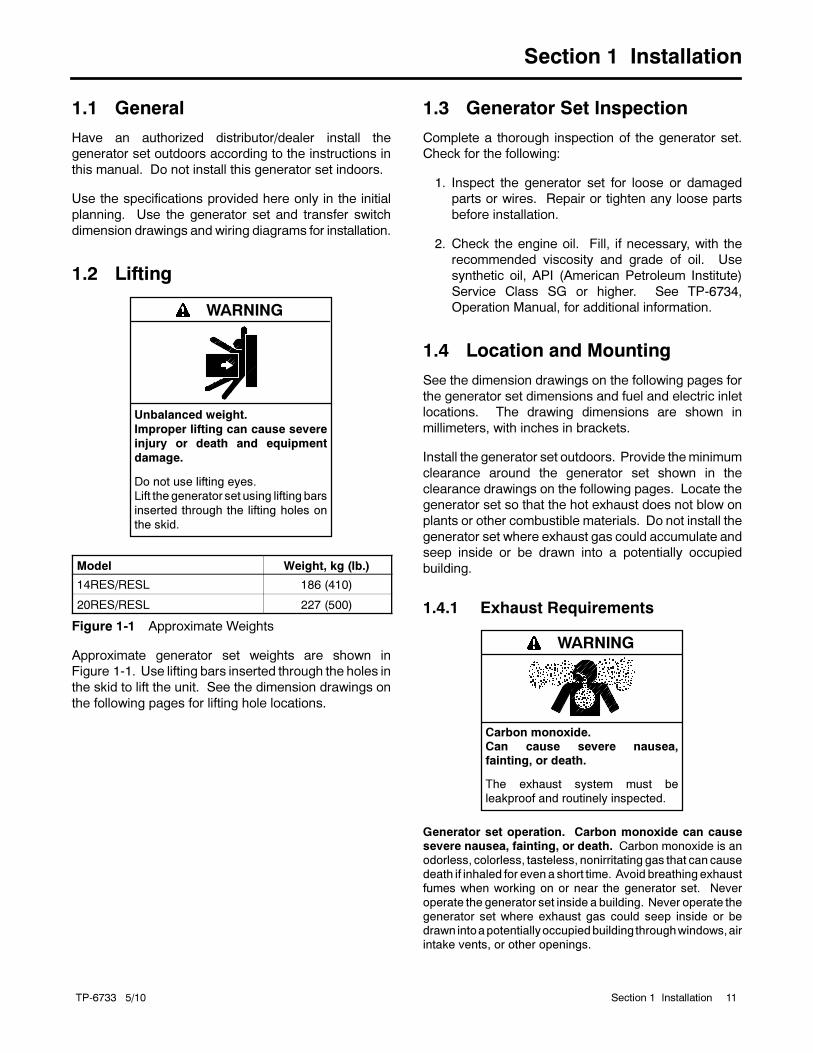
1.2 Lifting
Unbalanced weight.
Improper lifting can cause severe
injury or death and equipment
damage.
Do not use lifting eyes.
Lift the generator set using lifting bars
inserted through the lifting holes on
the skid.
WARNING
Model Weight, kg (lb.)
14RES/RESL 186 (410)
20RES/RESL 227 (500)
Figure 1-1 Approximate Weights
Approximate generator set weights are shown in
Figure 1-1. Use lifting bars inserted through the holes in
the skid to lift the unit. See the dimension drawings on
the following pages for lifting hole locations.
1.3 Generator Set Inspection
Complete a thorough inspection of the generator set.
Check for the following:
1. Inspect the generator set for loose or damaged
parts or wires. Repair or tighten any loose parts
before installation.
2. Check the engine oil. Fill, if necessary, with the
recommended viscosity and grade of oil. Use
synthetic oil, API (American Petroleum Institute)
Service Class SG or higher. See TP-6734,
Operation Manual, for additional information.
1.4 Location and Mounting
See the dimension drawings on the following pages for
the generator set dimensions and fuel and electric inlet
locations. The drawing dimensions are shown in
millimeters, with inches in brackets.
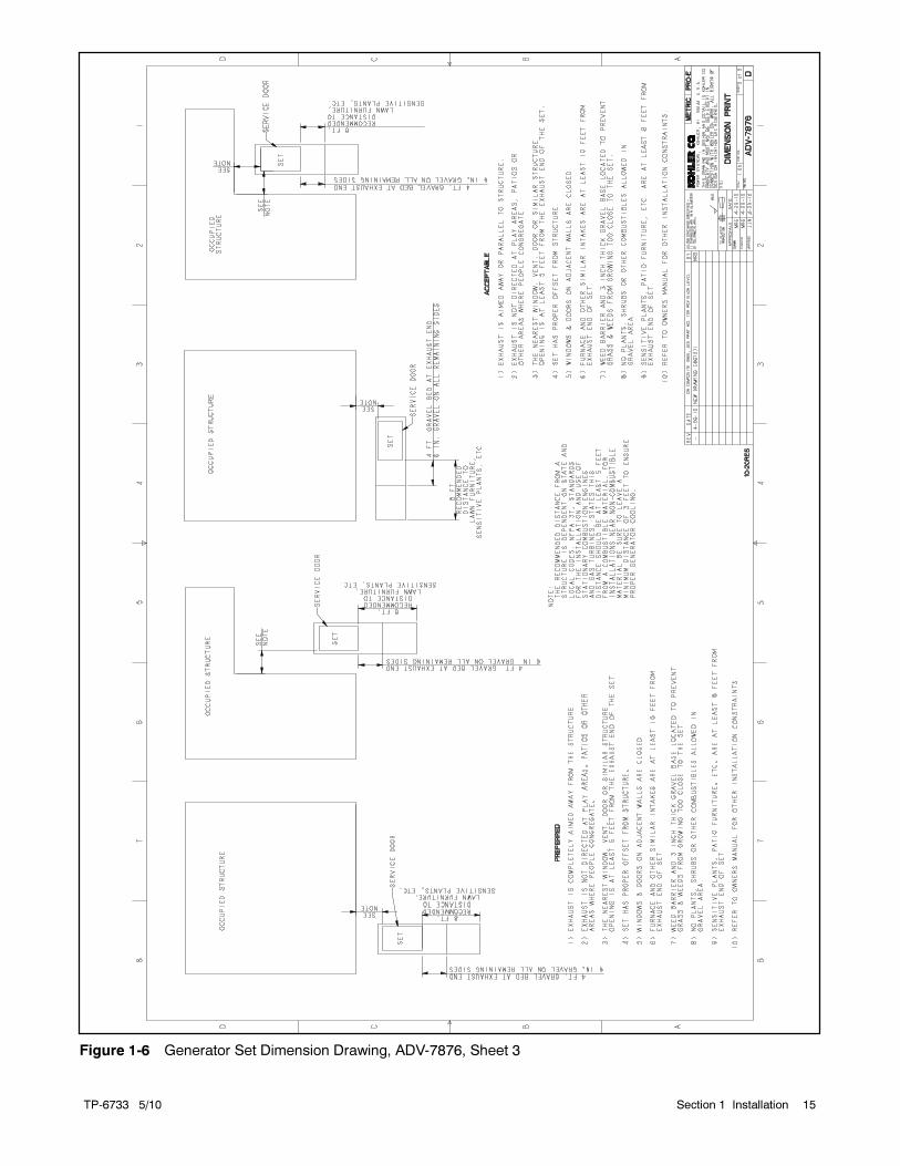
Install the generator set outdoors. Provide theminimum
clearance around the generator set shown in the
clearance drawings on the following pages. Locate the
generator set so that the hot exhaust does not blow on
plants or other combustible materials. Do not install the
generator set where exhaust gas could accumulate and
seep inside or be drawn into a potentially occupied
building.
1.4.1 Exhaust Requirements
Carbon monoxide.Can cause severe nausea,fainting, or death.
The exhaust system must be
leakproof and routinely inspected.
WARNING
Generator set operation. Carbon monoxide can causesevere nausea, fainting, or death. Carbon monoxide is anodorless, colorless, tasteless, nonirritating gas that can causedeath if inhaled for evena short time. Avoid breathingexhaustfumes when working on or near the generator set. Never
operate the generator set inside a building. Never operate thegenerator set where exhaust gas could seep inside or bedrawn intoapotentiallyoccupiedbuilding throughwindows,airintake vents, or other openings.

TP-6733 5/1012 Section 1 Installation
The exhaust system is complete for generator sets
installed outdoors. Do not install this generator set
indoors.
Figure 1-2 gives the exhaust temperature at rated load.
The engine exhaust mixes with the generator set
cooling air at the exhaust end of the enclosure. Mount
the generator set so that the hot exhaust does not blow
on plants or other combustible materials. Maintain the
clearances shown in Figure 1-6.
ExhaustTemperature,
C (F)
Exhaust gas exiting the enclosureat rated kW, C (F) 260 (500)
Figure 1-2 Exhaust Flow and Temperature
The generator set requires correct air flow for cooling
and combustion. The inlet and outlet openings in the
sound enclosure provide the cooling and combustion
air. Figure 1-3 shows the locations of the cooling air
intake and exhaust vents. Inspect the air inlet and outlet
openings inside and outside the housing to ensure that
the air flow is not blocked.
The generator set is designed to operate with all
enclosure panels and internal baffling in place. If during
installation, maintenance or repair the unit must be
operated without the complete enclosure and baffling as
shipped from the factorymake sure the exhaust panel is
removed as well.
tp6733
1. Air intake
2. Exhaust outlet
12
1
REAR VIEW
Figure 1-3 Cooling Air Intake and Exhaust
1.4.2 Mounting Area
The generator set is shipped on a plastic mounting pad.
Prepare a flat, level mounting area covered with a weed
barrier and gravel or a concrete mounting pad. Set the
plastic mounting pad directly on the gravel or concrete.
Do not install the mounting pad directly on grass, wood,
or other combustible materials. See Figure 1-6.
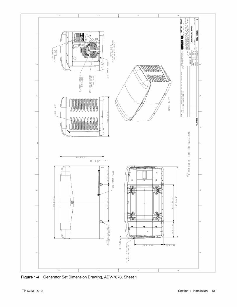
TP-6733 5/10 13Section 1 Installation
Figure 1-4 Generator Set Dimension Drawing, ADV-7876, Sheet 1
TP-6733 5/1014 Section 1 Installation
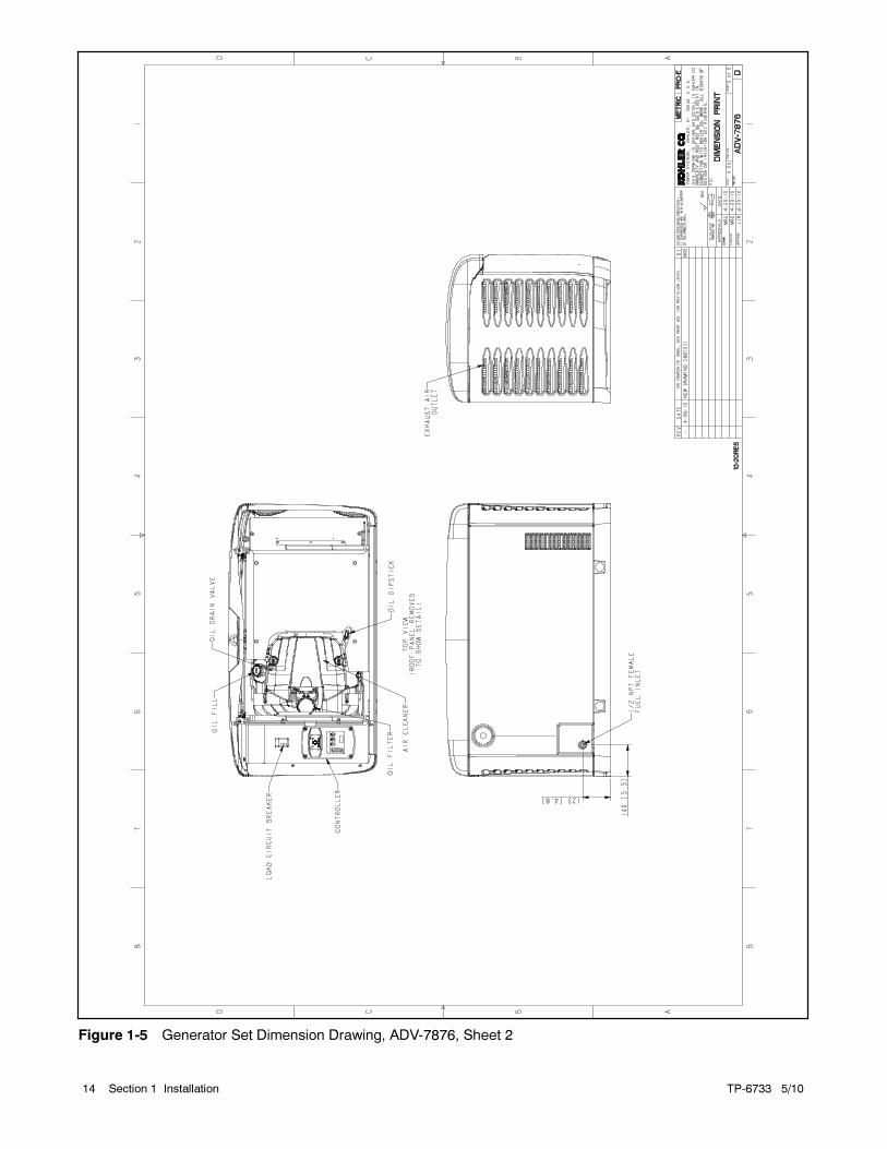
Figure 1-5 Generator Set Dimension Drawing, ADV-7876, Sheet 2
TP-6733 5/10 15Section 1 Installation
Figure 1-6 Generator Set Dimension Drawing, ADV-7876, Sheet 3
TP-6733 5/1016 Section 1 Installation
25 12REAR VIEW
23
18
19
24
17
14
AIR INTAKE SIDE --PANELREMOVED TO SHOW DETAIL
1
23
10
4
9
11
ADV-7876
8
5
13
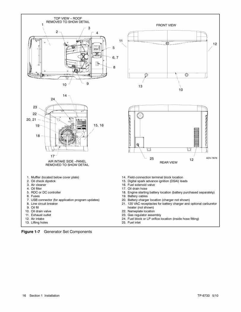
1. Muffler (located below cover plate)
2. Oil check dipstick3. Air cleaner
4. Oil filter
5. RDC or DC controller6. Fuses
7. USB connector (for application program updates)
8. Line circuit breaker
9. Oil fill10. Oil drain valve
11. Exhaust outlet
12. Air intake13. Lifting holes
14. Field-connection terminal block location
15. Digital spark advance ignition (DSAI) leads16. Fuel solenoid valve
17. Oil drain hose
18. Engine starting battery location (battery purchased separately)19. Battery cables
20. Battery charger location (charger not shown)
21. 120 VAC receptacles for battery charger and optional carburetor
heater (not shown)22. Nameplate location
23. Gas regulator assembly
24. Fuel block or LP orifice location (inside hose fitting)25. Fuel inlet
12
FRONT VIEW
TOP VIEW -- ROOFREMOVED TO SHOW DETAIL
6, 7
15, 16
22
20, 21
10
Figure 1-7 Generator Set Components

TP-6733 5/10 17Section 1 Installation
1.5 Fuel Requirements
The generator set operates using natural gas or LP
vapor fuel. The generator set is EPA-certified for both
natural gas and LP vapor fuels.
The fuel system installation must comply with the NEC
and local codes.
1.5.1 Fuel Supply
Because of variable climates and geographical
considerations, contact the local fuel supplier for fuel
system planning and installation. Figure 1-8 lists the
recommended fuel ratings and other fuel supply
information for natural gas and LP vapor fuels.
Fuel typeNaturalGas
LPVapor
Fuel supply inlet 1/2 NPT
Fuel supply pressure,kPa (in. H2O),
1.3--2.7(5--11)
1.7--2.7(7--11)
Fuel flow rate, maximum, Btu/hr.:
14RES/RESL 193,000 281,000
20RES/RESL 242,000 340,000
Nominal Fuel Rating, Btu/ft.3
Natural gas 1000
LP vapor 2500
Figure 1-8 Fuel Supply
Verify that the output pressure from the primary gas
utility (or LP tank) pressure regulator is 1.7--2.7 kPa
(7--11 in. water column) and that the utility gas meter
flow rate is sufficient to supply the generator set at rated
load plus all other gas-consuming appliances. See
Figure 1-10 for fuel consumption. Contact the fuel
supplier for flow rate information or a gas meter
upgrade.
Figure 1-4 shows the location of the fuel inlet
connection. Use flexible sections to prevent fuel line
breakage caused by vibration. Hold the fuel solenoid
valve with a wrench when tightening the fuel
connections. Protect all fuel lines from machinery or
equipment contact, adverse weather conditions, and
environmental damage.
1.5.2 Fuel Pipe Size
Ensure that the fuel pipe size and length meet the
specifications in Figure 1-9. Measure the pipe length
from the primary gas pressure regulator to the pipe
connection on the generator set fuel inlet. Add 2.4 m
(8 ft.) to the measured length for each 90 degree elbow.
Compare the total pipe length with the chart in
Figure 1-9 to find the required pipe size.
Contact local LP provider for LP installation information.
Minimum Gas Pipe Size Recommendation, in. NPT
PipeLength,m (ft.)
14RES/RESL 20RES/RESL
NaturalGas
(193,000Btu/hr.)
LP Vapor(203,000Btu/hr.)
NaturalGas
(281,000Btu/hr.)
LP Vapor(340,000Btu/hr.)
8 (25) 3/4 3/4 1 3/4
15 (50) 1 3/4 1 1
30 (100) 1 1 1 1/4 1
46 (150) 1 1/4 1 1 1/4 1 1/4
61 (200) 1 1/4 1 1 1/4 1 1/4
Figure 1-9 Fuel Pipe Size Recommendations
Fuel Type % Load
Fuel Consumption, m3/hr. (cfh)
14RES/RESL 20RES/RESL
60 Hz 50 Hz 60 Hz 50 Hz
Natural Gas
100% 5.4 (193) 4.9 (175) 8.0 (281) 6.4 (225)
75% 4.7 (163) 4.2 (148) 6.9 (243) 5.4 (189)
50% 3.5 (124) 3.1 (108) 4.6 (161) 3.9 (139)
25% 2.6 (93) 2.4 (84) 3.6 (127) 2.9 (103)
LP Vapor
100% 2.3 (81) 2.1 (74) 3.9 (136) 2.9 (102)
75% 2.1 (75) 1.9 (68) 3.1 (109) 2.4 (85)
50% 1.8 (60) 1.5 (53) 2.3 (82) 1.8 (63)
25% 1.2 (45) 1.1 (40) 1.7 (59) 1.3 (47)
LP vapor conversion factors:8.58 ft.3 = 1 lb.0.535 m3 = 1 kg36.39 ft.3 = 1 gal.
Nominal fuel rating:Natural gas: 37 MJ/m3 (1000 Btu/ft.3)LP vapor: 93 MJ/m3 (2500 Btu/ft.3)
Figure 1-10 Fuel Consumption
TP-6733 5/1018 Section 1 Installation
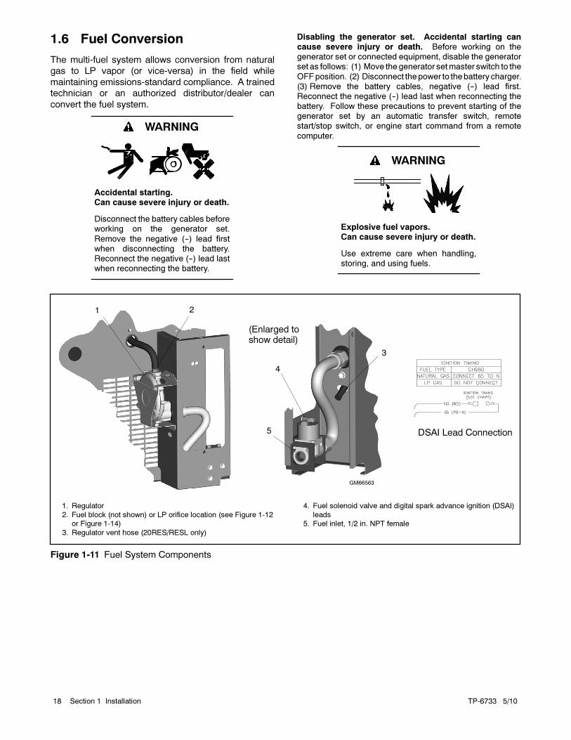
1.6 Fuel Conversion
The multi-fuel system allows conversion from natural
gas to LP vapor (or vice-versa) in the field while
maintaining emissions-standard compliance. A trained
technician or an authorized distributor/dealer can
convert the fuel system.
Accidental starting.Can cause severe injury or death.
Disconnect the battery cables beforeworking on the generator set.
Remove the negative (--) lead firstwhen disconnecting the battery.Reconnect the negative (--) lead lastwhen reconnecting the battery.
WARNING
Disabling the generator set. Accidental starting cancause severe injury or death. Before working on thegenerator set or connected equipment, disable the generatorset as follows: (1) Move thegenerator setmaster switch to the
OFFposition. (2) Disconnect thepower to thebattery charger.(3) Remove the battery cables, negative (--) lead first.Reconnect the negative (--) lead last when reconnecting thebattery. Follow these precautions to prevent starting of thegenerator set by an automatic transfer switch, remotestart/stop switch, or engine start command from a remote
computer.
Explosive fuel vapors.Can cause severe injury or death.
Use extreme care when handling,storing, and using fuels.
WARNING
1
GM66563
1. Regulator
2. Fuel block (not shown) or LP orifice location (see Figure 1-12or Figure 1-14)
3. Regulator vent hose (20RES/RESL only)
4. Fuel solenoid valve and digital spark advance ignition (DSAI)
leads5. Fuel inlet, 1/2 in. NPT female
4
2
5
(Enlarged toshow detail)
3
DSAI Lead Connection
Figure 1-11 Fuel System Components

TP-6733 5/10 19Section 1 Installation
1.6.1 Fuel Conversion, 14RES/RESL
Two fuel connections on the fuel block allow field-
conversion between natural gas and LP vapor. The fuel
metering valves are factory-set and sealed to comply
with applicable emission standards and to provide the
best possible hot and cold starting.
Note: Do not adjust the factory-sealed fuel-metering
adjustments on the fuel block. Changing the fuel-
metering adjustmentsmay violate federal or state
laws.
Use the following procedure to convert from natural gas
(NG) to LP vapor, moving the fuel connection from the
natural gas to the LP port, plugging the natural gas port,
and disconnecting the leads for the digital spark
advance ignition (DSAI). See Figure 1-11 for the fuel
system component locations.
Procedure to convert from NG to LP, 14RES/RESL
1. Press the OFF button on the generator set
controller.
2. Disconnect the power to the battery charger.
3. Disconnect the generator set engine starting
battery, negative (--) lead first.
4. Turn off the fuel supply.
5. Remove the hose clamp and fuel hose from the
hose fitting in the fuel block. See Figure 1-12.
5
GM66563
1. Fuel block
2. Fuel metering valves—factory-sealed, do not adjust3. Fuel inlet, 1/2 in. NPT
4. Hose fitting
5. Plug
1
2
3
4 Natural gassetup shown
Figure 1-12 Fuel Block, 14RES/RESL
6. Remove the hose fitting from the natural gas outlet
port in the fuel block. See Figure 1-12.
7. Remove the plug from the LP port in the fuel block.
See Figure 1-12.
8. Clean the plug with a dry cloth or brush, apply fresh
pipe sealant, and install the plug into the natural
gas outlet port.
9. Clean the hose fitting with a dry cloth or brush,
apply fresh pipe sealant to the threads, and install
the fitting into the LP port.
Note: Do not adjust the fuel metering valves.
10. Slide the hose onto the hose fitting and secure it
with the clamp.
11. Disconnect the DSAI leads for LP. See Figure 1-11
for the location of the DSAI leads.
Fuel DSAI Leads 65 and N
Natural Gas Connect lead 65 to N
LP Disconnect
Figure 1-13 DSAI Connection
12. Connect and turn on the new fuel supply.
13. Check that the generator set is off. Check that the
OFF LED on the controller is flashing.
14. Reconnect the generator set engine starting
battery leads, negative (--) lead last.
15. Reconnect power to the battery charger.
16. Start the generator set by pressing the RUN button
on the generator set controller.
17. Check for leaks using a gas leak detector.
18. Run the generator set and check the operation.
Use the controller to adjust the output and stability if
necessary. See Section 1.12 for instructions.
19. Press theOFF button to to shut down the generator
set.
To convert from LP vapor to natural gas, follow the same
fuel conversion procedure, moving the hose fitting to the
natural gas port and plugging the LP port. Connect the
DSAI leads for natural gas. See Figure 1-13.
TP-6733 5/1020 Section 1 Installation
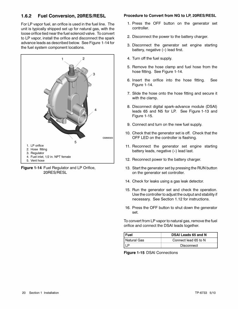
1.6.2 Fuel Conversion, 20RES/RESL
For LP vapor fuel, an orifice is used in the fuel line. The
unit is typically shipped set up for natural gas, with the
loose orifice tied near the fuel solenoid valve. To convert
to LP vapor, install the orifice and disconnect the spark
advance leads as described below. See Figure 1-14 for
the fuel system component locations.
1. LP orifice
2. Hose fitting3. Regulator
4. Fuel inlet, 1/2 in. NPT female
5. Vent hose
2
GM66563
4
5
3
1
Figure 1-14 Fuel Regulator and LP Orifice,
20RES/RESL
Procedure to Convert from NG to LP, 20RES/RESL
1. Press the OFF button on the generator set
controller.
2. Disconnect the power to the battery charger.
3. Disconnect the generator set engine starting
battery, negative (--) lead first.
4. Turn off the fuel supply.
5. Remove the hose clamp and fuel hose from the
hose fitting. See Figure 1-14.
6. Insert the orifice into the hose fitting. See
Figure 1-14.
7. Slide the hose onto the hose fitting and secure it
with the clamp.
8. Disconnect digital spark-advance module (DSAI)
leads 65 and N5 for LP. See Figure 1-13 and
Figure 1-15.
9. Connect and turn on the new fuel supply.
10. Check that the generator set is off. Check that the
OFF LED on the controller is flashing.
11. Reconnect the generator set engine starting
battery leads, negative (--) lead last.
12. Reconnect power to the battery charger.
13. Start the generator set by pressing the RUN button
on the generator set controller.
14. Check for leaks using a gas leak detector.
15. Run the generator set and check the operation.
Use the controller to adjust the output and stability if
necessary. See Section 1.12 for instructions.
16. Press the OFF button to shut down the generator
set.
To convert from LP vapor to natural gas, remove the fuel
orifice and connect the DSAI leads together.
Fuel DSAI Leads 65 and N
Natural Gas Connect lead 65 to N
LP Disconnect
Figure 1-15 DSAI Connections
TP-6733 5/10 21Section 1 Installation
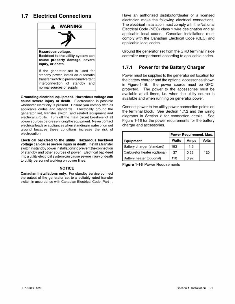
1.7 Electrical Connections
Hazardous voltage.
Backfeed to the utility system can
cause property damage, severe
injury, or death.
If the generator set is used for
standby power, install an automatic
transfer switch to prevent inadvertent
interconnection of standby and
normal sources of supply.
WARNING
Grounding electrical equipment. Hazardous voltage cancause severe injury or death. Electrocution is possiblewhenever electricity is present. Ensure you comply with all
applicable codes and standards. Electrically ground thegenerator set, transfer switch, and related equipment andelectrical circuits. Turn off the main circuit breakers of allpower sourcesbefore servicing theequipment. Never contactelectrical leadsor applianceswhenstanding inwater or onwetground because these conditions increase the risk of
electrocution.
Electrical backfeed to the utility. Hazardous backfeedvoltage can cause severe injury or death. Install a transferswitch instandbypower installations toprevent theconnectionof standby and other sources of power. Electrical backfeedinto a utility electrical system can cause severe injury or death
to utility personnel working on power lines.
NOTICE
Canadian installations only. For standby service connect
the output of the generator set to a suitably rated transferswitch in accordance with Canadian Electrical Code, Part 1.
Have an authorized distributor/dealer or a licensed
electrician make the following electrical connections.
The electrical installation must comply with the National
Electrical Code (NEC) class 1 wire designation and all
applicable local codes. Canadian installations must
comply with the Canadian Electrical Code (CEC) and
applicable local codes.
Ground the generator set from the GRD terminal inside
controller compartment according to applicable codes.
1.7.1 Power for the Battery Charger
Power must be supplied to the generator set location for
the battery charger and the optional accessories shown
in Figure 1-16. the power source must be GFCI
protected. The power to the accessories must be
available at all times, i.e. when the utility source is
available and when running on generator power.
Connect power to the utility power connection points on
the terminal block. See Section 1.7.2 and the wiring
diagrams in Section 2 for connection details. See
Figure 1-16 for the power requirements for the battery
charger and accessories.
Equipment
Power Requirement, Max.
Watts Amps Volts
Battery charger (standard) 192 1.6
120Carburetor heater (optional) 37 0.33
Battery heater (optional) 110 0.92
Figure 1-16 Power Requirements
TP-6733 5/1022 Section 1 Installation
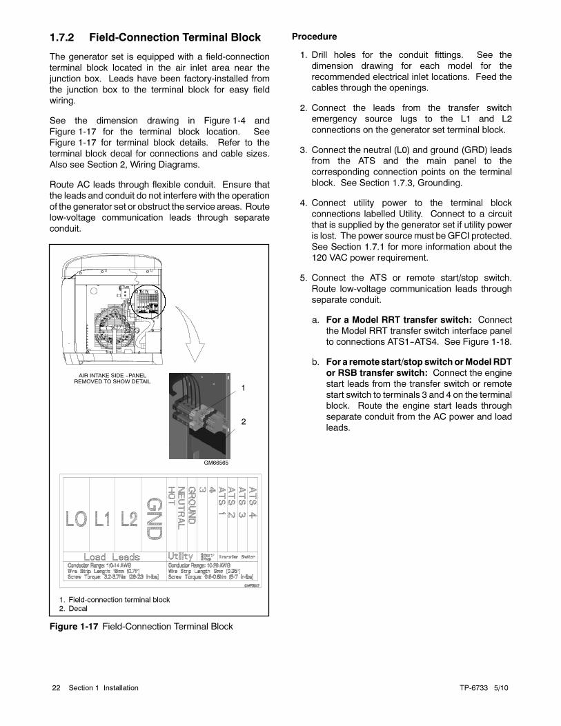
1.7.2 Field-Connection Terminal Block
The generator set is equipped with a field-connection
terminal block located in the air inlet area near the
junction box. Leads have been factory-installed from
the junction box to the terminal block for easy field
wiring.
See the dimension drawing in Figure 1-4 and
Figure 1-17 for the terminal block location. See
Figure 1-17 for terminal block details. Refer to the
terminal block decal for connections and cable sizes.
Also see Section 2, Wiring Diagrams.
Route AC leads through flexible conduit. Ensure that
the leads and conduit do not interfere with the operation
of the generator set or obstruct the service areas. Route
low-voltage communication leads through separate
conduit.
GM66565
1
1. Field-connection terminal block
2. Decal
2
AIR INTAKE SIDE --PANELREMOVED TO SHOW DETAIL
Figure 1-17 Field-Connection Terminal Block
Procedure
1. Drill holes for the conduit fittings. See the
dimension drawing for each model for the
recommended electrical inlet locations. Feed the
cables through the openings.
2. Connect the leads from the transfer switch
emergency source lugs to the L1 and L2
connections on the generator set terminal block.
3. Connect the neutral (L0) and ground (GRD) leads
from the ATS and the main panel to the
corresponding connection points on the terminal
block. See Section 1.7.3, Grounding.
4. Connect utility power to the terminal block
connections labelled Utility. Connect to a circuit
that is supplied by the generator set if utility power
is lost. The power source must be GFCI protected.
See Section 1.7.1 for more information about the
120 VAC power requirement.
5. Connect the ATS or remote start/stop switch.
Route low-voltage communication leads through
separate conduit.
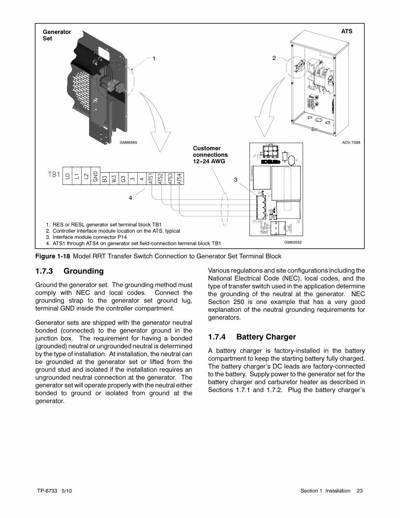
a. For a Model RRT transfer switch: Connect
the Model RRT transfer switch interface panel
to connections ATS1--ATS4. See Figure 1-18.
b. For a remote start/stop switchorModelRDT
or RSB transfer switch: Connect the engine
start leads from the transfer switch or remote
start switch to terminals 3 and 4 on the terminal
block. Route the engine start leads through
separate conduit from the AC power and load
leads.
TP-6733 5/10 23Section 1 Installation
GM63552
1
ADV-7598
1. RES or RESL generator set terminal block TB1
2. Controller interface module location on the ATS, typical3. Interface module connector P14
4. ATS1 through ATS4 on generator set field-connection terminal block TB1
4
2
3
GM66565
GeneratorSet
ATS
Customerconnections12--24 AWG
Figure 1-18 Model RRT Transfer Switch Connection to Generator Set Terminal Block
1.7.3 Grounding
Ground the generator set. The grounding method must
comply with NEC and local codes. Connect the
grounding strap to the generator set ground lug,
terminal GND inside the controller compartment.
Generator sets are shipped with the generator neutral
bonded (connected) to the generator ground in the
junction box. The requirement for having a bonded
(grounded) neutral or ungrounded neutral is determined
by the type of installation. At installation, the neutral can
be grounded at the generator set or lifted from the
ground stud and isolated if the installation requires an
ungrounded neutral connection at the generator. The
generator set will operate properly with the neutral either
bonded to ground or isolated from ground at the
generator.
Various regulations and site configurations including the
National Electrical Code (NEC), local codes, and the
type of transfer switch used in the application determine
the grounding of the neutral at the generator. NEC
Section 250 is one example that has a very good
explanation of the neutral grounding requirements for
generators.
1.7.4 Battery Charger
A battery charger is factory-installed in the battery
compartment to keep the starting battery fully charged.
The battery charger’s DC leads are factory-connected
to the battery. Supply power to the generator set for the
battery charger and carburetor heater as described in
Sections 1.7.1 and 1.7.2. Plug the battery charger’s
TP-6733 5/1024 Section 1 Installation
power cord into the receptacle on the bottom of the
controller junction box.
Refer to the generator set operation manual for battery
charger operation information.
1.8 Battery
Sulfuric acid in batteries.Can cause severe injury or death.
Wear protective goggles andclothing. Battery acid may cause
blindness and burn skin.
WARNING
Explosion.Can cause severe injury or death.Relays in the battery chargercause arcs or sparks.
Locate the battery in awell-ventilatedarea. Isolate thebattery charger fromexplosive fumes.
WARNING
Battery electrolyte is a diluted sulfuric acid. Battery acid
can cause severe injury or death. Battery acid can causeblindness and burn skin. Always wear splashproof safetygoggles, rubber gloves, and boots when servicing the battery.Do not open a sealed battery or mutilate the battery case. Ifbattery acid splashes in the eyes or on the skin, immediatelyflush the affected area for 15 minutes with large quantities of
clean water. Seek immediate medical aid in the case of eyecontact. Never addacid to a battery after placing the battery inservice, as this may result in hazardous spattering of batteryacid.
Battery acid cleanup. Battery acid can cause severeinjury or death. Battery acid is electrically conductive and
corrosive. Add 500 g (1 lb.) of bicarbonate of soda (bakingsoda) to a container with 4 L (1 gal.) of water and mix theneutralizing solution. Pour the neutralizing solution on thespilled battery acid and continue to add the neutralizingsolution to the spilled battery acid until all evidence of achemical reaction (foaming) has ceased. Flush the resulting
liquid with water and dry the area.
Battery gases. Explosion can cause severe injury ordeath. Battery gases can cause an explosion. Do not smokeor permit flames or sparks to occur near a battery at any time,particularlywhen it is charging. Donot disposeof abattery ina
fire. To prevent burns and sparks that could cause anexplosion, avoid touching the battery terminals with tools orother metal objects. Remove all jewelry before servicing theequipment. Discharge static electricity from your body beforetouching batteries by first touching a grounded metal surfaceaway from the battery. To avoid sparks, do not disturb the
battery charger connections while the battery is charging.Always turn the battery charger off before disconnecting thebattery connections. Ventilate the compartments containingbatteries to prevent accumulation of explosive gases.
Battery short circuits. Explosion can cause severe injuryor death. Short circuits can cause bodily injury and/or
equipment damage. Disconnect the battery before generatorset installation or maintenance. Remove all jewelry beforeservicing the equipment. Use tools with insulated handles.Remove the negative (--) lead first when disconnecting thebattery. Reconnect the negative (--) lead last whenreconnecting the battery. Never connect the negative (--)
battery cable to the positive (+) connection terminal of thestarter solenoid. Do not test the battery condition by shortingthe terminals together.
Connecting the battery and the battery charger.Hazardous voltage can cause severe injury or death.Reconnect the battery correctly, positive to positive andnegative to negative, to avoid electrical shock and damage to
the battery charger and battery(ies). Have a qualifiedelectrician install the battery(ies).
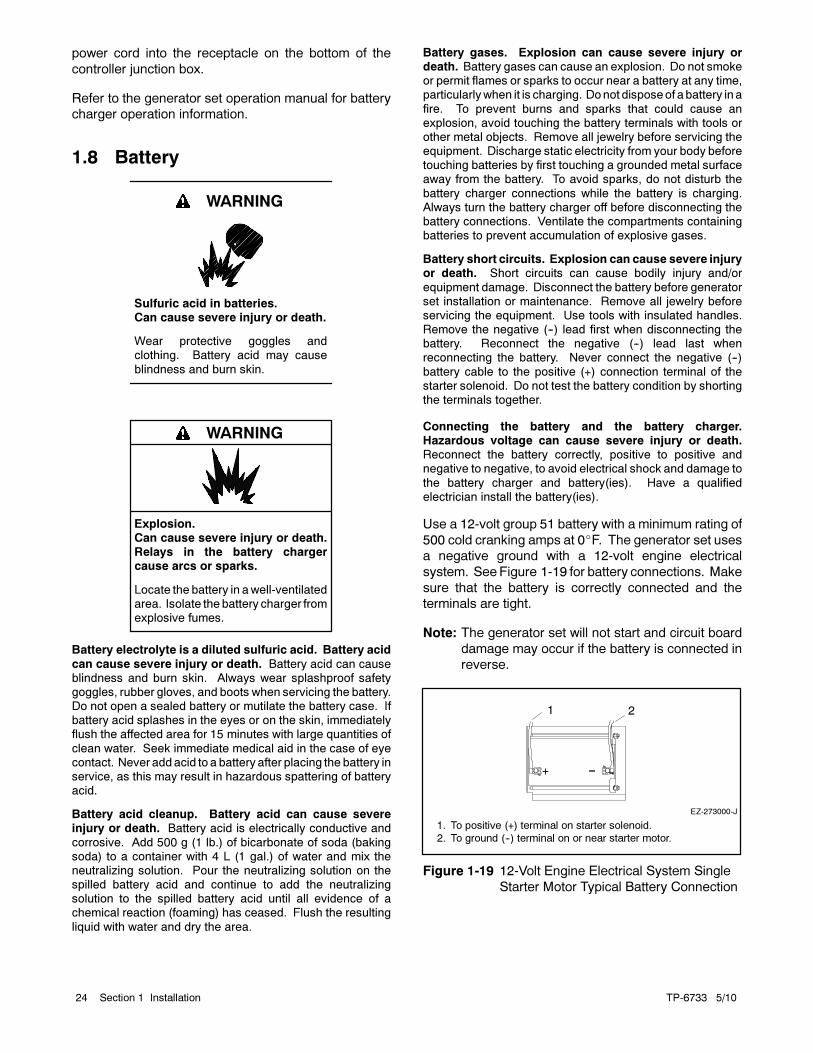
Use a 12-volt group 51 battery with a minimum rating of
500 cold cranking amps at 0F. The generator set uses
a negative ground with a 12-volt engine electrical
system. See Figure 1-19 for battery connections. Make
sure that the battery is correctly connected and the
terminals are tight.
Note: The generator set will not start and circuit board
damage may occur if the battery is connected in
reverse.
EZ-273000-J
1 2
1. To positive (+) terminal on starter solenoid.
2. To ground (--) terminal on or near starter motor.
Figure 1-19 12-Volt Engine Electrical System Single
Starter Motor Typical Battery Connection
TP-6733 5/10 25Section 1 Installation
See the dimension drawing in Figure 1-4 for the engine
starting battery location on the air intake side of the
generator set. Standard battery cables provide easy
connection to the battery. Use the following procedure
to install and connect the battery.
Battery Installation Procedure
1. Ensure that the starting battery is fully charged
before placing the battery in service.
2. Clean the battery posts and/or adapters if
necessary.
3. Install the battery post adapters, if needed.
4. Place the battery in the housing.
5. Verify that the generator set is off. Check that the
OFF LED on the controller is flashing.
6. Connect the positive (+) lead to the engine starting
battery.
7. Connect the negative (--) lead to the engine starting
battery.
Refer to the generator set operation manual and the
battery manufacturer’s instructions for battery
maintenance instructions.
1.9 Carburetor Heater
Have accessories installed by an authorized distributor/
dealer or a licensed electrician. Follow the installation
instructions providedwith each kit. Use separate conduit
for ACandDC leads to reduce the possibility of electrical
interference. Verify that the leads and conduit do not
interfere with the operation of the generator set or
obstruct the service areas. Verify that the electrical
installation complies with the National Electrical Code
(NEC) and all applicable local codes. See Section 2,
Wiring Diagrams, for more information regarding
generator set electrical connections.
An optional carburetor heater is recommended for
improved cold starting in locations where the ambient
temperature drops below 0C (32F). The carburetor
heater prevents condensation and carburetor icing. The
heater turns on when the temperature at the thermostat
falls below approximately 4C (40F) and turns off when
the temperature rises above approximately 16C
(60F). See Figure 1-20, Figure 1-21, and Figure 1-22.
The heater thermostat is installed in the cord.
Figure 1-22 shows the location of the thermostat on the
power cord. The heater power cord and thermostat are
located in the generator set housing air intake area/
battery compartment.
Note: Do not place the heater thermostat inside the
generator set engine compartment. The
thermostat must be exposed to the ambient air.
The heater requires a continuous source of power. Plug
the carburetor heater into one of the 120 VAC
receptacles provided.

TP-6733 5/1026 Section 1 Installation
tp6195
1. Carburetor heater (air cleaner removed to show heater)
2. Carburetor heater power cord
1 2
Figure 1-20 14RES/RESL Carburetor Heater
1
tp6514
1. Carburetor heater location
Figure 1-21 20RES/RESL Carburetor Heater
Location on Engine (bulkhead removed
to show heater location)
GM19463
23
14RES/RESL Carburetor Heater
2 3
20RES/RESL Carburetor Heater
GM57968
1
1
1. Power plug
2. Thermostat3. Heater
Figure 1-22 Carburetor Heaters
TP-6733 5/10 27Section 1 Installation
1.10 Prestart Installation Check
Review the entire installation section. Inspect all wiring
and connections to verify that the generator set is ready
for operation. Check all items in the following Prestart
Checklist.
Prestart Checklist
Air Cleaner. Check that a clean air cleaner element is
installed to prevent unfiltered air from entering the
engine. See the generator set operation manual for
instructions.
Air Inlets. Check for clean and unobstructed air inlets.
Battery. Check for tight battery connections. Consult
the battery manufacturer’s instructions regarding
battery care and maintenance.
Exhaust System. Check for exhaust leaks and
blockages. Check the muffler condition.
Inspect the exhaust system components for cracks,
leaks, and corrosion. Check for tight exhaust system
connections.
Check for corroded or brokenmetal parts and replace
them as needed.
Check that the exhaust outlet is unobstructed.
Oil Level. Maintain the oil level at or near, not over, the
full mark on the dipstick.
Operating Area. Check for obstructions that could
block the flow of cooling air. Keep the air intake area
clean. Do not leave rags, tools, or debris on or near the
generator set.
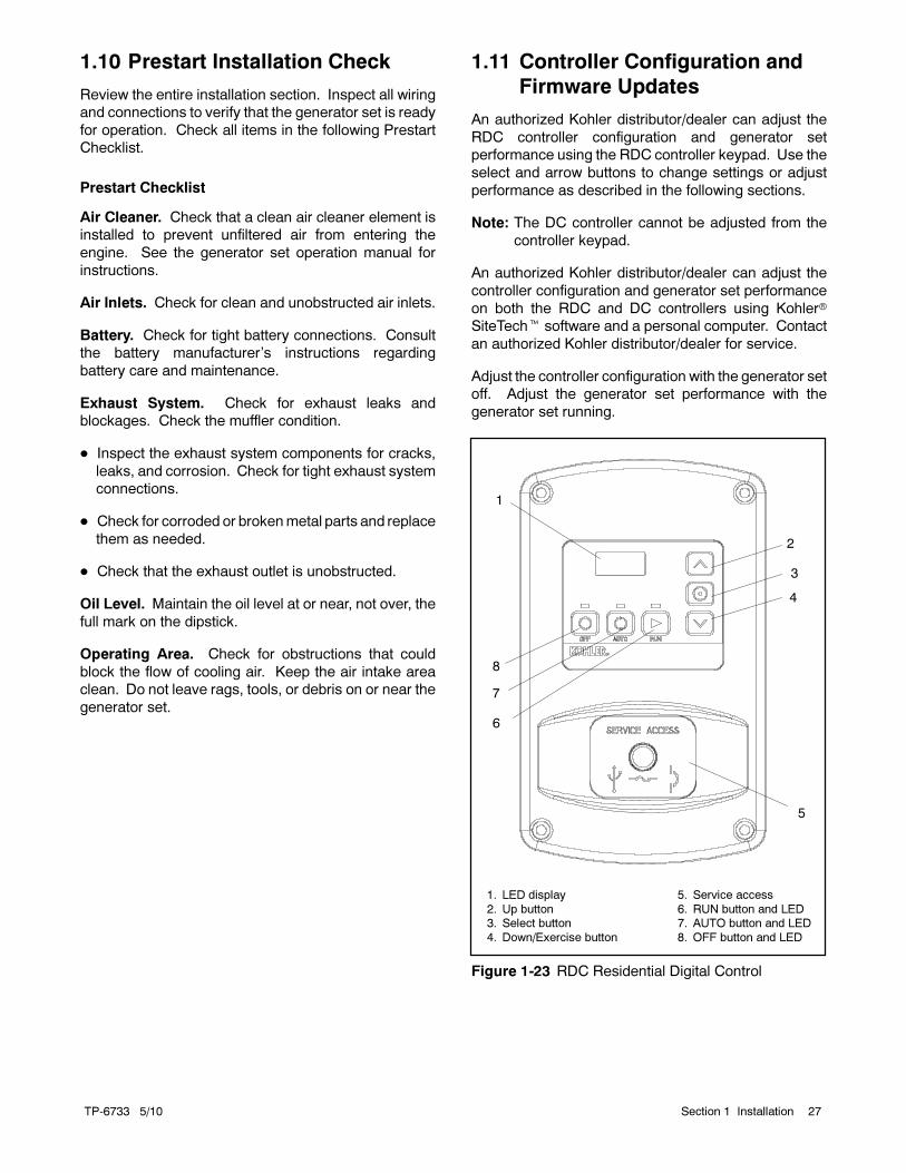
1.11 Controller Configuration and
Firmware Updates
An authorized Kohler distributor/dealer can adjust the
RDC controller configuration and generator set
performance using the RDC controller keypad. Use the
select and arrow buttons to change settings or adjust
performance as described in the following sections.
Note: The DC controller cannot be adjusted from the
controller keypad.
An authorized Kohler distributor/dealer can adjust the
controller configuration and generator set performance
on both the RDC and DC controllers using Kohler
SiteTech software and a personal computer. Contact
an authorized Kohler distributor/dealer for service.
Adjust the controller configuration with the generator set
off. Adjust the generator set performance with the
generator set running.
1. LED display
2. Up button3. Select button
4. Down/Exercise button
5. Service access
6. RUN button and LED7. AUTO button and LED
8. OFF button and LED
1
8
3
2
6
7
5
4
Figure 1-23 RDC Residential Digital Control

TP-6733 5/1028 Section 1 Installation
1.11.1 Firmware Version and Update
To check the firmware version number on the RDC
controller, hold the select button and the up arrow button
for about 5 seconds, until the firmware version number
appears on the display. See Figure 1-25.
The manufacturer may release new versions of
controller firmware. An authorized Kohler distributor or
dealer can update the controller firware in the field.
Kohler SiteTech software and a personal computer
are required.
1.11.2 System Parameters
The controller configuration for each generator model is
set at the factory and should not normally require
changes. The controller’s configuration mode allows
adjustment of the system parameters listed in this
section. Use the instructions in this section to check the
configuration after installation and change them to
match the settings shown in Figure 1-24 for your
application, if necessary.
Parameter Setting
Definition
Phases Hz VAC
System voltageand frequency *
Uu01 1 60 120/240
Uu06 1 50 115/230
Uu07 DO NOT USE
Uu11 DO NOT USE
Uu15 DO NOT USE
Uu16 DO NOT USE
Uu19 DO NOT USE
Uu21 DO NOT USE
Uu22 DO NOT USE
EngineConfiguration *
Ec13 14RES/RESL
Ec14 20RES/RESL
* Factory-set for each model.
Figure 1-24 Controller Configuration Parameters
1.11.3 RDC Controller Configuration
In order to prevent inadvertent changes, a code is
required to enter configuration mode. With the
controller inOFF, hold the select button and press the up
arrow button for 5 seconds. The controller display will
show the software version. Press the arrow buttons in
the following order to enter configuration mode: down,
up, down, up, down, up.
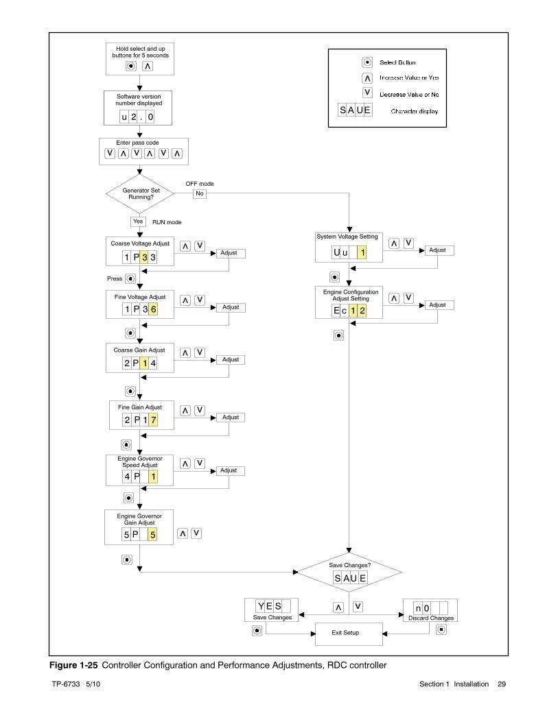
Follow the instructions in Figure 1-25 to enter the
configuration mode while the engine is not running and
then step through the following parameters. Use the up
(∧) and down (∨) arrowbuttons to select the appropriate
settings for the application.
If no buttons are pressed for one minute, the controller
will automatically exit the configuration mode without
saving any changes. Start the configuration procedure
over again from the beginning if the controller exits the
configuration mode before the settings have been
saved.
Note: Be sure to save your settings before exiting the
configuration mode. The controller reverts to the
last saved settings when the OFF button is
pressed.
System voltage/frequency setting (Uu). Select the
system voltage and frequency from the table in
Figure 1-24.
Note: The Uu parameter sets the system’s rated
voltage and frequency. To adjust the output
(measured) voltage and frequency, see Section
1.12, Voltage and Frequency Adjustments.
Engine configuration (Ec). The engine configuration
must match the generator set engine type.
TP-6733 5/10 29Section 1 Installation
Yes
Engine GovernorGain Adjust
2 P 1 4
2 P 1 7
4 P 1
5 P 5
S A UE
Coarse Gain Adjust
Fine Gain Adjust
Engine GovernorSpeed Adjust
Save Changes
Save Changes?
Discard Changes
Y E S n 0
Exit Setup
System Voltage Setting
Engine ConfigurationAdjust Setting
1uU
E c 1 2
NoGenerator SetRunning?
Hold select and upbuttons for 5 seconds
Enter pass code
S AU E
Software versionnumber displayed
u 1 . 0
Software versionnumber displayed
u 2 . 0
Adjust
Adjust
Adjust
Adjust
Adjust
OFF mode
RUN mode
1 P 3 6
1 P 3 3
Coarse Voltage Adjust
Fine Voltage Adjust
Press
Adjust
Adjust
Figure 1-25 Controller Configuration and Performance Adjustments, RDC controller
TP-6733 5/1030 Section 1 Installation
1.12 Performance Adjustments,
RDC Controller
Hazardous voltage.Can cause severe injury or death.
Operate the generator set only whenall guards and electrical enclosures
are in place.
Moving parts.
WARNING
Short circuits. Hazardous voltage/current can causesevere injury or death. Short circuits can cause bodily injuryand/or equipment damage. Do not contact electricalconnections with tools or jewelry whilemaking adjustments orrepairs. Remove all jewelry before servicing the equipment.
The generator output voltage and frequency can be
adjusted, if necessary. Have adjustments performed by
an authorized distributor/ dealer or service technician.
The generator set must be running during performance
adjustments.
Note: Controller configuration and performance
adjustments from the controller keypad are not
available with the DC controller.
Note: A digital multimeter that measures voltage and
frequency is required for these adjustments.
Use a digital multimeter to check the output voltage and
frequency. If output voltage or frequency is not within
specifications, use the controller keypad to adjust the
output voltage and engine speed (frequency) while the
generator set is running. See Figure 1-23. The
flowchart in Figure 1-25 outlines the adjustment
procedures.
Note: Be sure to save your changes as instructed in
Figure 1-25 before exiting configuration mode.
Changes in voltage and speed adjustments are lost if
not saved before the generator set shuts down. The
generator set continues to runwith the new settings until
it shuts down but then reverts to the previous settings at
the next startup if the changes have not been saved.
An authorized Kohler distributor/dealer can adjust the
controller configuration and generator set performance
on both the RDC and DC controllers using Kohler
SiteTech software and a personal computer. Contact
an authorized Kohler distributor/dealer for service.
1.12.1 Voltage Adjustment
Note: Refer to the flowchart in Figure 1-25 during the
following procedure.
Voltage Adjustment Procedure
1. With the generator set off, connect a digital
multimeter to the output leads or an electrical outlet
on the load side of the generator set. Set themeter
to measure AC voltage.
2. Start the generator set by pressing the RUN button
on the RDC controller.
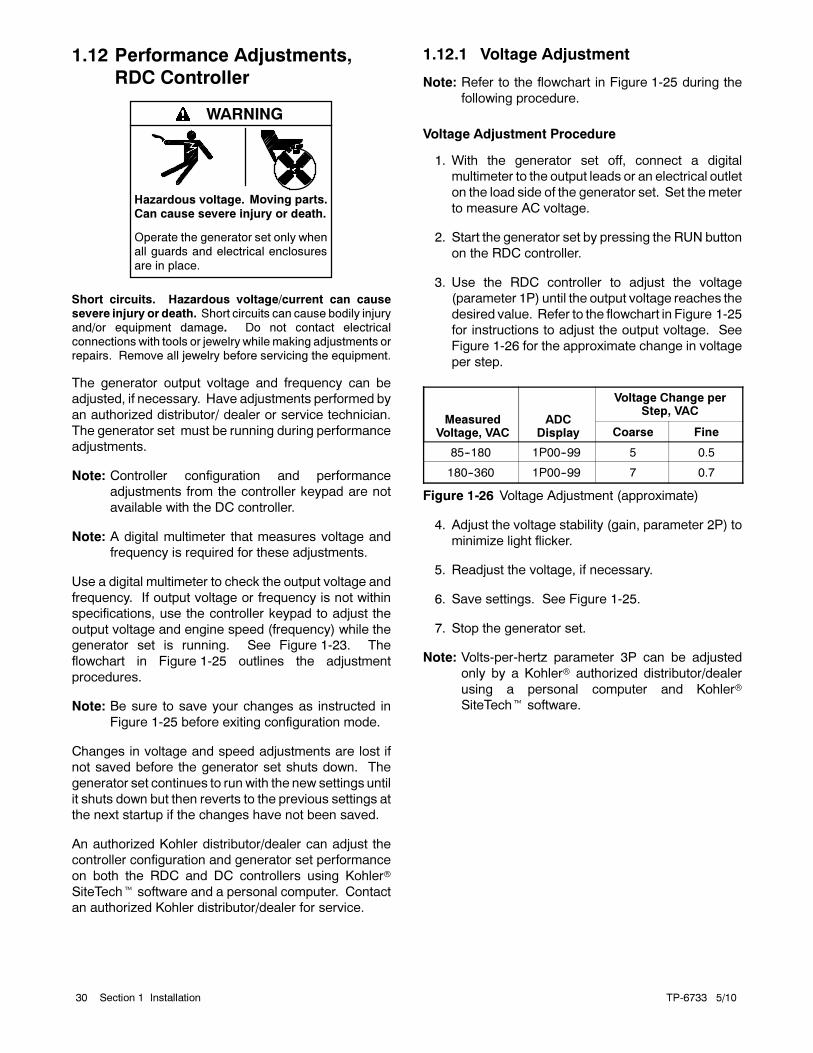
3. Use the RDC controller to adjust the voltage
(parameter 1P) until the output voltage reaches the
desired value. Refer to the flowchart in Figure 1-25
for instructions to adjust the output voltage. See
Figure 1-26 for the approximate change in voltage
per step.
MeasuredVoltage, VAC
ADCDisplay
Voltage Change perStep, VAC
Coarse Fine
85--180 1P00--99 5 0.5
180--360 1P00--99 7 0.7
Figure 1-26 Voltage Adjustment (approximate)
4. Adjust the voltage stability (gain, parameter 2P) to
minimize light flicker.
5. Readjust the voltage, if necessary.
6. Save settings. See Figure 1-25.
7. Stop the generator set.
Note: Volts-per-hertz parameter 3P can be adjusted
only by a Kohler authorized distributor/dealer
using a personal computer and Kohler
SiteTech software.
TP-6733 5/10 31Section 1 Installation
1.12.2 Frequency Adjustment
The engine speed determines the generator output
frequency; 60 Hz units operate at 3600 rpm and 50 Hz
units run at 3000 rpm. Adjust the engine governor
speed and gain to set the output frequency and stability
using the following procedure.
Note: Refer to the flowchart in Figure 1-25 during the
following procedure.
Frequency Adjustment Procedure
Note: Refer to the flowchart in Figure 1-25 during the
following procedure.
1. Attach a frequency meter to the AC output leads or
an electrical outlet on the load side of the generator
set.
2. Start and run the generator set until it reaches
normal operating temperature (at least 10 minutes).
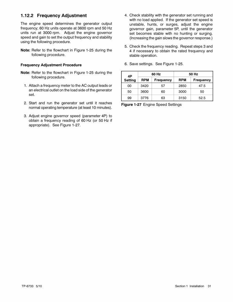
3. Adjust engine governor speed (parameter 4P) to
obtain a frequency reading of 60 Hz (or 50 Hz if
appropriate). See Figure 1-27.
4. Check stability with the generator set running and
with no load applied. If the generator set speed is
unstable, hunts, or surges, adjust the engine
governor gain, parameter 5P, until the generator
set becomes stable with no hunting or surging.
(Increasing the gain slows the governor response.)
5. Check the frequency reading. Repeat steps 3 and
4 if necessary to obtain the rated frequency and
stable operation.
6. Save settings. See Figure 1-25.
4PSetting
60 Hz 50 Hz
RPM Frequency RPM Frequency
00 3420 57 2850 47.5
50 3600 60 3000 50
99 3776 63 3150 52.5
Figure 1-27 Engine Speed Settings

TP-6733 5/1032 Section 1 Installation
Notes

TP-6733 5/10 33Section 2 Wiring Diagrams
Section 2 Wiring Diagrams
Figure 2-1 lists the wiring diagram numbers and locations.
Wiring Diagram Description Drawing Number Page
Schematic Diagram ADV-7697 34
Point-to-Point Wiring Diagram GM69754 35
Figure 2-1 Wiring Diagrams and Schematics

TP-6733 5/1034 Section 2 Wiring Diagrams
-
Figure 2-2 Schematic Diagram, ADV-7697
TP-6733 5/10 35Section 2 Wiring Diagrams
-
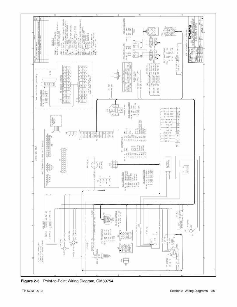
Figure 2-3 Point-to-Point Wiring Diagram, GM69754

TP-6733 5/1036 Section 2 Wiring Diagrams
Notes
TP-6733 5/10 Appendix 37
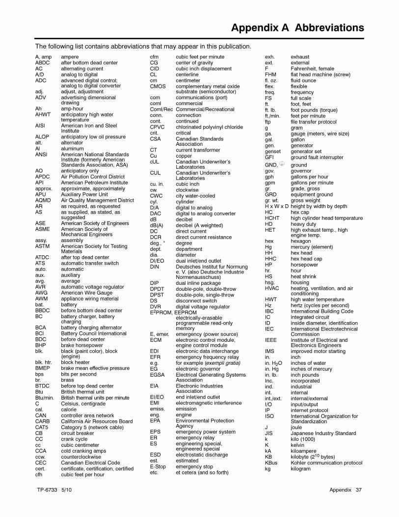
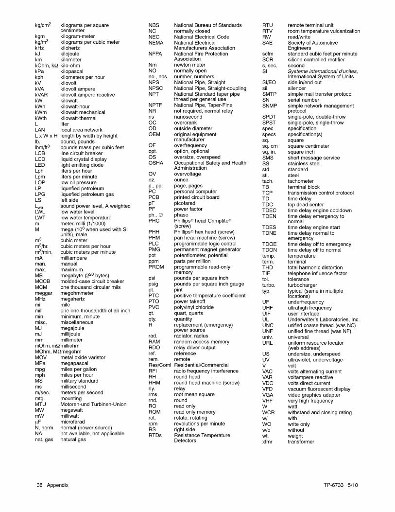
Appendix A Abbreviations
The following list contains abbreviations that may appear in this publication.
A, amp ampereABDC after bottom dead centerAC alternating currentA/D analog to digitalADC advanced digital control;
analog to digital converteradj. adjust, adjustmentADV advertising dimensional
drawingAh amp-hourAHWT anticipatory high water
temperatureAISI American Iron and Steel
InstituteALOP anticipatory low oil pressurealt. alternatorAl aluminumANSI American National Standards
Institute (formerly AmericanStandards Association, ASA)
AO anticipatory onlyAPDC Air Pollution Control DistrictAPI American Petroleum Instituteapprox. approximate, approximatelyAPU Auxiliary Power UnitAQMD Air Quality Management DistrictAR as required, as requestedAS as supplied, as stated, as
suggestedASE American Society of EngineersASME American Society of
Mechanical Engineersassy. assemblyASTM American Society for Testing
MaterialsATDC after top dead centerATS automatic transfer switchauto. automaticaux. auxiliaryavg. averageAVR automatic voltage regulatorAWG American Wire GaugeAWM appliance wiring materialbat. batteryBBDC before bottom dead centerBC battery charger, battery
chargingBCA battery charging alternatorBCI Battery Council InternationalBDC before dead centerBHP brake horsepowerblk. black (paint color), block
(engine)blk. htr. block heaterBMEP brake mean effective pressurebps bits per secondbr. brassBTDC before top dead centerBtu British thermal unitBtu/min. British thermal units per minuteC Celsius, centigradecal. calorieCAN controller area networkCARB California Air Resources BoardCAT5 Category 5 (network cable)CB circuit breakerCC crank cyclecc cubic centimeterCCA cold cranking ampsccw. counterclockwiseCEC Canadian Electrical Codecert. certificate, certification, certifiedcfh cubic feet per hour
cfm cubic feet per minuteCG center of gravityCID cubic inch displacementCL centerlinecm centimeterCMOS complementary metal oxide
substrate (semiconductor)com communications (port)coml commercialComl/Rec Commercial/Recreationalconn. connectioncont. continuedCPVC chlorinated polyvinyl chloridecrit. criticalCSA Canadian Standards
AssociationCT current transformerCu coppercUL Canadian Underwriter’s
LaboratoriesCUL Canadian Underwriter’s
Laboratoriescu. in. cubic inchcw. clockwiseCWC city water-cooledcyl. cylinderD/A digital to analogDAC digital to analog converterdB decibeldB(A) decibel (A weighted)DC direct currentDCR direct current resistancedeg., ° degreedept. departmentdia. diameterDI/EO dual inlet/end outletDIN Deutsches Institut fur Normung
e. V. (also Deutsche IndustrieNormenausschuss)
DIP dual inline packageDPDT double-pole, double-throwDPST double-pole, single-throwDS disconnect switchDVR digital voltage regulatorE2PROM, EEPROM
electrically-erasableprogrammable read-onlymemory
E, emer. emergency (power source)ECM electronic control module,
engine control moduleEDI electronic data interchangeEFR emergency frequency relaye.g. for example (exempli gratia)EG electronic governorEGSA Electrical Generating Systems
AssociationEIA Electronic Industries
AssociationEI/EO end inlet/end outletEMI electromagnetic interferenceemiss. emissioneng. engineEPA Environmental Protection
AgencyEPS emergency power systemER emergency relayES engineering special,
engineered specialESD electrostatic dischargeest. estimatedE-Stop emergency stopetc. et cetera (and so forth)
exh. exhaustext. externalF Fahrenheit, femaleFHM flat head machine (screw)fl. oz. fluid ounceflex. flexiblefreq. frequencyFS full scaleft. foot, feetft. lb. foot pounds (torque)ft./min. feet per minuteftp file transfer protocolg gramga. gauge (meters, wire size)gal. gallongen. generatorgenset generator setGFI ground fault interrupter
GND, groundgov. governorgph gallons per hourgpm gallons per minutegr. grade, grossGRD equipment groundgr. wt. gross weightH x W x D height by width by depthHC hex capHCHT high cylinder head temperatureHD heavy dutyHET high exhaust temp., high
engine temp.hex hexagonHg mercury (element)HH hex headHHC hex head capHP horsepowerhr. hourHS heat shrinkhsg. housingHVAC heating, ventilation, and air
conditioningHWT high water temperatureHz hertz (cycles per second)IBC International Building CodeIC integrated circuitID inside diameter, identificationIEC International Electrotechnical
CommissionIEEE Institute of Electrical and
Electronics EngineersIMS improved motor startingin. inchin. H2O inches of waterin. Hg inches of mercuryin. lb. inch poundsInc. incorporatedind. industrialint. internalint./ext. internal/externalI/O input/outputIP internet protocolISO International Organization for
StandardizationJ jouleJIS Japanese Industry Standardk kilo (1000)K kelvinkA kiloampereKB kilobyte (210 bytes)KBus Kohler communication protocolkg kilogram
TP-6733 5/1038 Appendix
kg/cm2 kilograms per squarecentimeter
kgm kilogram-meterkg/m3 kilograms per cubic meterkHz kilohertzkJ kilojoulekm kilometerkOhm, kΩ kilo-ohmkPa kilopascalkph kilometers per hourkV kilovoltkVA kilovolt amperekVAR kilovolt ampere reactivekW kilowattkWh kilowatt-hourkWm kilowatt mechanicalkWth kilowatt-thermalL literLAN local area networkL x W x H length by width by heightlb. pound, poundslbm/ft3 pounds mass per cubic feetLCB line circuit breakerLCD liquid crystal displayLED light emitting diodeLph liters per hourLpm liters per minuteLOP low oil pressureLP liquefied petroleumLPG liquefied petroleum gasLS left sideLwa sound power level, A weightedLWL low water levelLWT low water temperaturem meter, milli (1/1000)M mega (106 when used with SI
units), malem3 cubic meterm3/hr. cubic meters per hourm3/min. cubic meters per minutemA milliampereman. manualmax. maximumMB megabyte (220 bytes)MCCB molded-case circuit breakerMCM one thousand circular milsmeggar megohmmeterMHz megahertzmi. milemil one one-thousandth of an inchmin. minimum, minutemisc. miscellaneousMJ megajoulemJ millijoulemm millimetermOhm,mΩmilliohmMOhm, MΩmegohmMOV metal oxide varistorMPa megapascalmpg miles per gallonmph miles per hourMS military standardms millisecondm/sec. meters per secondmtg. mountingMTU Motoren-und Turbinen-UnionMW megawattmW milliwattμF microfaradN, norm. normal (power source)NA not available, not applicablenat. gas natural gas
NBS National Bureau of StandardsNC normally closedNEC National Electrical CodeNEMA National Electrical
Manufacturers AssociationNFPA National Fire Protection
AssociationNm newton meterNO normally openno., nos. number, numbersNPS National Pipe, StraightNPSC National Pipe, Straight-couplingNPT National Standard taper pipe
thread per general useNPTF National Pipe, Taper-FineNR not required, normal relayns nanosecondOC overcrankOD outside diameterOEM original equipment
manufacturerOF overfrequencyopt. option, optionalOS oversize, overspeedOSHA Occupational Safety and Health
AdministrationOV overvoltageoz. ouncep., pp. page, pagesPC personal computerPCB printed circuit boardpF picofaradPF power factorph., ∅ phasePHC Phillips head Crimptite
(screw)PHH Phillips hex head (screw)PHM pan head machine (screw)PLC programmable logic controlPMG permanent magnet generatorpot potentiometer, potentialppm parts per millionPROM programmable read-only
memorypsi pounds per square inchpsig pounds per square inch gaugept. pintPTC positive temperature coefficientPTO power takeoffPVC polyvinyl chlorideqt. quart, quartsqty. quantityR replacement (emergency)
power sourcerad. radiator, radiusRAM random access memoryRDO relay driver outputref. referencerem. remoteRes/Coml Residential/CommercialRFI radio frequency interferenceRH round headRHM round head machine (screw)rly. relayrms root mean squarernd. roundRO read onlyROM read only memoryrot. rotate, rotatingrpm revolutions per minuteRS right sideRTDs Resistance Temperature
Detectors
RTU remote terminal unitRTV room temperature vulcanizationRW read/writeSAE Society of Automotive
Engineersscfm standard cubic feet per minuteSCR silicon controlled rectifiers, sec. secondSI Systeme international d’unites,
International System of UnitsSI/EO side in/end outsil. silencerSMTP simple mail transfer protocolSN serial numberSNMP simple network management
protocolSPDT single-pole, double-throwSPST single-pole, single-throwspec specificationspecs specification(s)sq. squaresq. cm square centimetersq. in. square inchSMS short message serviceSS stainless steelstd. standardstl. steeltach. tachometerTB terminal blockTCP transmission control protocolTD time delayTDC top dead centerTDEC time delay engine cooldownTDEN time delay emergency to
normalTDES time delay engine startTDNE time delay normal to
emergencyTDOE time delay off to emergencyTDON time delay off to normaltemp. temperatureterm. terminalTHD total harmonic distortionTIF telephone influence factortol. toleranceturbo. turbochargertyp. typical (same in multiple
locations)UF underfrequencyUHF ultrahigh frequencyUIF user interfaceUL Underwriter’s Laboratories, Inc.UNC unified coarse thread (was NC)UNF unified fine thread (was NF)univ. universalURL uniform resource locator
(web address)US undersize, underspeedUV ultraviolet, undervoltageV voltVAC volts alternating currentVAR voltampere reactiveVDC volts direct currentVFD vacuum fluorescent displayVGA video graphics adapterVHF very high frequencyW wattWCR withstand and closing ratingw/ withWO write onlyw/o withoutwt. weightxfmr transformer


2010 by Kohler Co. All rights reserved.
TP-6733 5/10
KOHLER CO. Kohler, Wisconsin 53044Phone 920-565-3381, Fax 920-459-1646For the nearest sales/service outlet in theUS and Canada, phone 1-800-544-2444KohlerPower.com
Kohler Power SystemsAsia Pacific Headquarters7 Jurong Pier RoadSingapore 619159Phone (65) 6264-6422, Fax (65) 6264-6455