residential plumbing chapters 25-33
TRANSCRIPT

Residential Plumbing Chapters 25-33
Refer to the 2011 Oregon Plumbing Specialty Code.
2011 OREGON RESIDENTIAL SPECIALTY CODE 25–33-1
1M:\data\CODES\STATE CODES\Oregon\2011\Residential\Final VP\25-33_Oregon_Res_2011.vpWednesday, April 20, 2011 1:22:56 PM
Color profile: Generic CMYK printer profileComposite Default screen

25–33—2 2011 OREGON RESIDENTIAL SPECIALTY CODE
2M:\data\CODES\STATE CODES\Oregon\2011\Residential\Final VP\25-33_Oregon_Res_2011.vpWednesday, April 20, 2011 1:22:56 PM
Color profile: Generic CMYK printer profileComposite Default screen

Residential Electrical Chapters 34-42
Refer to the 2011 Oregon Electrical Specialty Code.
2011 OREGON RESIDENTIAL SPECIALTY CODE 34–42-1
1M:\data\CODES\STATE CODES\Oregon\2011\Residential\Final VP\34-42_Oregon_Res_2011.vpWednesday, April 20, 2011 1:22:34 PM
Color profile: Generic CMYK printer profileComposite Default screen

34–42-2 2011 OREGON RESIDENTIAL SPECIALTY CODE
2M:\data\CODES\STATE CODES\Oregon\2011\Residential\Final VP\34-42_Oregon_Res_2011.vpWednesday, April 20, 2011 1:22:34 PM
Color profile: Generic CMYK printer profileComposite Default screen

CHAPTER 43
Deleted
2011 OREGON RESIDENTIAL SPECIALTY CODE 43-1
1M:\data\CODES\STATE CODES\Oregon\2011\Residential\Final VP\43_Oregon_Res_2011.vpWednesday, April 20, 2011 1:22:13 PM
Color profile: Generic CMYK printer profileComposite Default screen

43-2 2011 OREGON RESIDENTIAL SPECIALTY CODE
2M:\data\CODES\STATE CODES\Oregon\2011\Residential\Final VP\43_Oregon_Res_2011.vpWednesday, April 20, 2011 1:22:13 PM
Color profile: Generic CMYK printer profileComposite Default screen

Part IX—Referenced Standards
CHAPTER 44
REFERENCED STANDARDS
This chapter lists the standards that are referenced in various sections of this document. The standards are listed herein by thepromulgating agency of the standard, the standard identification, the effective date and title, and the section or sections of thisdocument that reference the standard. The application of the referenced standards shall be as specified in Section R102.4.
American Architectural Manufacturers Association1827 Walden Office Square, Suite 550Schaumburg, IL 60173AAMA
Standard Referencedreference in codenumber Title section number
AAMA/WDMA/CSA101/I.S.2/A440—08 North American Fenestration Standards/Specifications for Windows, Doors and Skylights . . . . . . . . . . . . . . . R308.6.9, R613.6
450—06 Voluntary Performance Rating Method for Mulled Fenestration Assemblies . . . . . . . . . . . . . . . . . . . . . . . . . . . . . . . . R612.11.1
506—06 Voluntary Specifications for Hurricane Impact and Cycle Testing of Fenestration Products. . . . . . . . . . . . . . . . . . . . . . R612.9.1
711—07 Voluntary Specification for Self Adhering Flashing Used for Installation of ExteriorWall Fenestration Products. . . . . . . . . . . . . . . . . . . . . . . . . . . . . . . . . . . . . . . . . . . . . . . . . . . . . . . . . . . . . . . . . . . . . . . .R703.8
American Concrete Institute38800 Country Club DriveFarmington Hills, MI 48331ACI
Standard Referencedreference in codenumber Title section number
318—08 Building Code Requirements for Structural Concrete . . . . . . . . . . . . . . . . . . . . . R301.2.2.2.4, R301.2.2.3.4, R402.2, R404.1.2,Table R404.1.2(5), Table R404.1.2(6), Table R404.1.2(7),
Table R404.1.2(8), Table R404.1.2(9), R404.1.2.1,R404.1.2.3, R404.1.2.4, R404.1.4.2, R404.5.1, R611.1, R611.1.1,
R611.1.2, R611.2, R611.5.1, R611.8.2, R611.9.2, R611.9.3
332—08 Code Requirements for Residential Concrete Construction. . . . . . . . . . . . . . R402.2, R403.1, R404.1.2, R404.1.2.4, R404.1.4.2
530—08 Building Code Requirements for Masonry Structures . . . . . . . . . . . . . . . . . . . . . . . . . . R404.1.1, R606.1, R606.1.1, R606.12.1,R606.12.2.3.1, R606.12.2.3.2, R606.12.3.1, Table R703.4
530.1—08 Specification for Masonry Structures . . . . . . . . . . . . . . . . . . . . . . . . . . . . . . . . . . . . . . .R404.1.1, R606.1, R606.1.1, R606.12.1,
R606.12.2.3.1, R606.12.2.3.2, R606.12.3.1, Table R703.4
Air Conditioning Contractors of America2800 Shirlington Road, Suite 300Arlington, VA 22206ACCA
Standard Referencedreference in codenumber Title section number
Manual D—95 Residential Duct Systems . . . . . . . . . . . . . . . . . . . . . . . . . . . . . . . . . . . . . . . . . . . . . . . . . . . . . . . . . . . . . . . . .M1601.1, M1602.2
Manual J—02 Residential Load Calculation—Eighth Edition. . . . . . . . . . . . . . . . . . . . . . . . . . . . . . . . . . . . . . . . . . . . . . . . . . . . . . . . .M1401.3
Manual S—04 Residential Equipment Selection. . . . . . . . . . . . . . . . . . . . . . . . . . . . . . . . . . . . . . . . . . . . . . . . . . . . . . . . . . . . . . . . . . . .M1401.3
2011 OREGON RESIDENTIAL SPECIALTY CODE 44-1
>
1M:\data\CODES\STATE CODES\Oregon\2011\Residential\Final VP\44_Oregon_Res_2011.vpMonday, May 02, 2011 11:56:54 AM
Color profile: Generic CMYK printer profileComposite Default screen
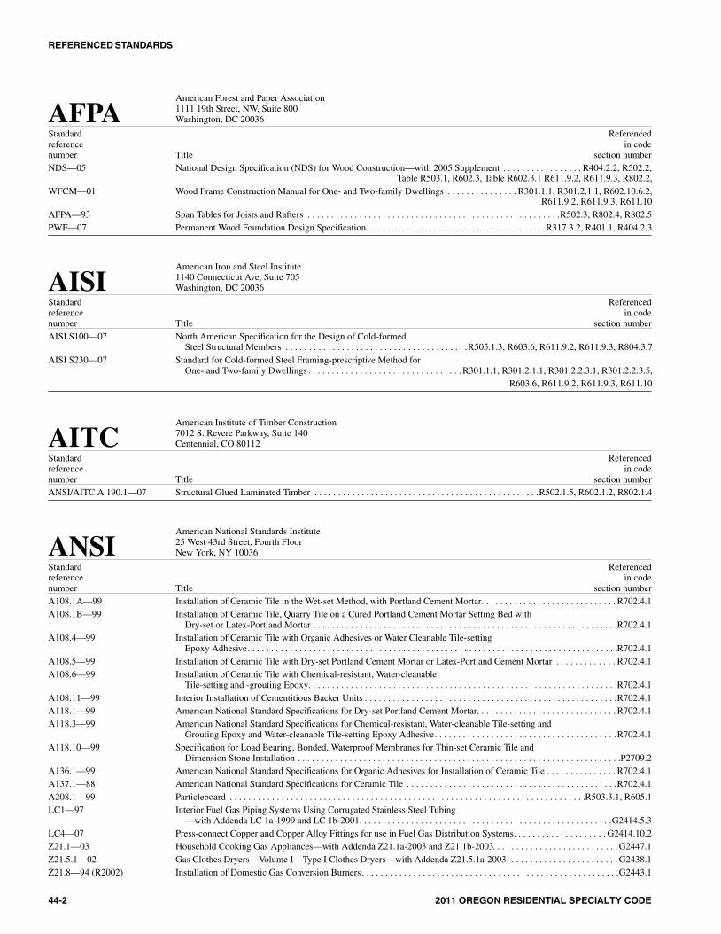
American Forest and Paper Association1111 19th Street, NW, Suite 800Washington, DC 20036AFPA
Standard Referencedreference in codenumber Title section numberNDS—05 National Design Specification (NDS) for Wood Construction—with 2005 Supplement . . . . . . . . . . . . . . . . . R404.2.2, R502.2,
Table R503.1, R602.3, Table R602.3.1 R611.9.2, R611.9.3, R802.2,WFCM—01 Wood Frame Construction Manual for One- and Two-family Dwellings . . . . . . . . . . . . . . . R301.1.1, R301.2.1.1, R602.10.6.2,
R611.9.2, R611.9.3, R611.10AFPA—93 Span Tables for Joists and Rafters . . . . . . . . . . . . . . . . . . . . . . . . . . . . . . . . . . . . . . . . . . . . . . . . . . . . . .R502.3, R802.4, R802.5PWF—07 Permanent Wood Foundation Design Specification . . . . . . . . . . . . . . . . . . . . . . . . . . . . . . . . . . . . . .R317.3.2, R401.1, R404.2.3
American Iron and Steel Institute1140 Connecticut Ave, Suite 705Washington, DC 20036AISI
Standard Referencedreference in codenumber Title section numberAISI S100—07 North American Specification for the Design of Cold-formed
Steel Structural Members . . . . . . . . . . . . . . . . . . . . . . . . . . . . . . . . . . . . . . .R505.1.3, R603.6, R611.9.2, R611.9.3, R804.3.7AISI S230—07 Standard for Cold-formed Steel Framing-prescriptive Method for
One- and Two-family Dwellings . . . . . . . . . . . . . . . . . . . . . . . . . . . . . . . . . R301.1.1, R301.2.1.1, R301.2.2.3.1, R301.2.2.3.5,R603.6, R611.9.2, R611.9.3, R611.10
American Institute of Timber Construction7012 S. Revere Parkway, Suite 140Centennial, CO 80112AITC
Standard Referencedreference in codenumber Title section numberANSI/AITC A 190.1—07 Structural Glued Laminated Timber . . . . . . . . . . . . . . . . . . . . . . . . . . . . . . . . . . . . . . . . . . . . . . . .R502.1.5, R602.1.2, R802.1.4
American National Standards Institute25 West 43rd Street, Fourth FloorNew York, NY 10036ANSI
Standard Referencedreference in codenumber Title section numberA108.1A—99 Installation of Ceramic Tile in the Wet-set Method, with Portland Cement Mortar. . . . . . . . . . . . . . . . . . . . . . . . . . . . . R702.4.1A108.1B—99 Installation of Ceramic Tile, Quarry Tile on a Cured Portland Cement Mortar Setting Bed with
Dry-set or Latex-Portland Mortar . . . . . . . . . . . . . . . . . . . . . . . . . . . . . . . . . . . . . . . . . . . . . . . . . . . . . . . . . . . . . . . . .R702.4.1A108.4—99 Installation of Ceramic Tile with Organic Adhesives or Water Cleanable Tile-setting
Epoxy Adhesive. . . . . . . . . . . . . . . . . . . . . . . . . . . . . . . . . . . . . . . . . . . . . . . . . . . . . . . . . . . . . . . . . . . . . . . . . . . . . . .R702.4.1A108.5—99 Installation of Ceramic Tile with Dry-set Portland Cement Mortar or Latex-Portland Cement Mortar . . . . . . . . . . . . . R702.4.1A108.6—99 Installation of Ceramic Tile with Chemical-resistant, Water-cleanable
Tile-setting and -grouting Epoxy. . . . . . . . . . . . . . . . . . . . . . . . . . . . . . . . . . . . . . . . . . . . . . . . . . . . . . . . . . . . . . . . . .R702.4.1A108.11—99 Interior Installation of Cementitious Backer Units . . . . . . . . . . . . . . . . . . . . . . . . . . . . . . . . . . . . . . . . . . . . . . . . . . . . . .R702.4.1A118.1—99 American National Standard Specifications for Dry-set Portland Cement Mortar. . . . . . . . . . . . . . . . . . . . . . . . . . . . . . R702.4.1A118.3—99 American National Standard Specifications for Chemical-resistant, Water-cleanable Tile-setting and
Grouting Epoxy and Water-cleanable Tile-setting Epoxy Adhesive. . . . . . . . . . . . . . . . . . . . . . . . . . . . . . . . . . . . . . .R702.4.1A118.10—99 Specification for Load Bearing, Bonded, Waterproof Membranes for Thin-set Ceramic Tile and
Dimension Stone Installation . . . . . . . . . . . . . . . . . . . . . . . . . . . . . . . . . . . . . . . . . . . . . . . . . . . . . . . . . . . . . . . . . . . . .P2709.2A136.1—99 American National Standard Specifications for Organic Adhesives for Installation of Ceramic Tile . . . . . . . . . . . . . . . R702.4.1A137.1—88 American National Standard Specifications for Ceramic Tile . . . . . . . . . . . . . . . . . . . . . . . . . . . . . . . . . . . . . . . . . . . . .R702.4.1A208.1—99 Particleboard . . . . . . . . . . . . . . . . . . . . . . . . . . . . . . . . . . . . . . . . . . . . . . . . . . . . . . . . . . . . . . . . . . . . . . . . . . . .R503.3.1, R605.1LC1—97 Interior Fuel Gas Piping Systems Using Corrugated Stainless Steel Tubing
—with Addenda LC 1a-1999 and LC 1b-2001. . . . . . . . . . . . . . . . . . . . . . . . . . . . . . . . . . . . . . . . . . . . . . . . . . . . . .G2414.5.3LC4—07 Press-connect Copper and Copper Alloy Fittings for use in Fuel Gas Distribution Systems. . . . . . . . . . . . . . . . . . . . G2414.10.2Z21.1—03 Household Cooking Gas Appliances—with Addenda Z21.1a-2003 and Z21.1b-2003. . . . . . . . . . . . . . . . . . . . . . . . . . . G2447.1Z21.5.1—02 Gas Clothes Dryers—Volume I—Type I Clothes Dryers—with Addenda Z21.5.1a-2003. . . . . . . . . . . . . . . . . . . . . . . . G2438.1Z21.8—94 (R2002) Installation of Domestic Gas Conversion Burners . . . . . . . . . . . . . . . . . . . . . . . . . . . . . . . . . . . . . . . . . . . . . . . . . . . . . . .G2443.1
REFERENCED STANDARDS
44-2 2011 OREGON RESIDENTIAL SPECIALTY CODE
2M:\data\CODES\STATE CODES\Oregon\2011\Residential\Final VP\44_Oregon_Res_2011.vpMonday, May 02, 2011 11:56:54 AM
Color profile: Generic CMYK printer profileComposite Default screen

ANSI—continued
Z21.10.1—04 Gas Water Heaters—Volume I—Storage Water Heaters with InputRatings of 75,000 Btu per hour or Less . . . . . . . . . . . . . . . . . . . . . . . . . . . . . . . . . . . . . . . . . . . . . . . . . . . . . . . . . . . . .G2448.1
Z21.10.3—01 Gas Water Heaters—Volume III—Storage Water Heaters with Input Ratings above 75,000 Btu per hour,Circulating and Instantaneous Water Heaters—with Addenda Z21.10.3a-2003 and Z21.10.3b-2004 . . . . . . . . . . . . . G2448.1
Z21.11.2—02 Gas-fired Room Heaters—Volume II—Unvented Room Heaters—with Addenda Z21.11.2a-2003. . . . . . . . . . . . . . . . G2445.1
Z21.13—04 Gas-fired Low-Pressure Steam and Hot Water Boilers . . . . . . . . . . . . . . . . . . . . . . . . . . . . . . . . . . . . . . . . . . . . . . . . . . .G2452.1
Z21.15—97 (R2003) Manually Operated Gas Valves for Appliances, Appliance Connector Valves and Hose EndValves—with Addenda Z21.15a-2001 (R2003) . . . . . . . . . . . . . . . . . . . . . . . . . . . . . . . . . . . . . . . . . . . . . . . .Table G2420.1.1
Z21.22—99 (R2003) Relief Valves for Hot Water Supply Systems—with Addenda Z21.22a-2000 (R2003) and21.22b-2001 (R2003). . . . . . . . . . . . . . . . . . . . . . . . . . . . . . . . . . . . . . . . . . . . . . . . . . . . . . . . . . . . . . . . . . . .P2803.2, P2803.7
Z21.24-97 Connectors for Gas Appliances . . . . . . . . . . . . . . . . . . . . . . . . . . . . . . . . . . . . . . . . . . . . . . . . . . . . . . . . . . . . . . . . . . . . .G2422.1
Z21.40.1—96 (R2002) Gas-fired, Heat-activated Air Conditioning and Heat Pump Appliances—with Z21.40.1a-97 (R2002) . . . . . . . . . . . . . G2449.1
Z21.40.2—96 (R2002) Gas-fired, Work-activated Air Conditioning and Heat Pump Appliances (Internal Combustion)—with Z21.40.2a-1997 (R2002) . . . . . . . . . . . . . . . . . . . . . . . . . . . . . . . . . . . . . . . . . . . . . . . . . . . . . . . . . . . . . . . . . .G2449.1
Z21.42—93 (R2002) Gas-fired Illuminating Appliances . . . . . . . . . . . . . . . . . . . . . . . . . . . . . . . . . . . . . . . . . . . . . . . . . . . . . . . . . . . . . . . . . . .G2450.1
Z21.47—03 Gas-fired Central Furnaces. . . . . . . . . . . . . . . . . . . . . . . . . . . . . . . . . . . . . . . . . . . . . . . . . . . . . . . . . . . . . . . . . . . . . . . . .G2442.1
Z21.50—03 Vented Gas Fireplaces—with Addenda Z21.50a-2003 . . . . . . . . . . . . . . . . . . . . . . . . . . . . . . . . . . . . . . . . . . . . . . . . . . .G2434.1
Z21.56—01 Gas-fired Pool Heaters—with Addenda Z21.56a-2004 and Z21.56b—2004 . . . . . . . . . . . . . . . . . . . . . . . . . . . . . . . . . .G2441.1
Z21.58—95 (R2002) Outdoor Cooking Gas Appliances—with Addenda Z21.58a-1998 (R2002) and Z21.58b-2002 . . . . . . . . . . . . . . . . . . . G2447.1
Z21.60—03 Decorative Gas Appliances for Installation in Solid Fuel Burning Fireplaces—with Addenda Z21.60a-2003 . . . . . . . . G2432.1
Z21.75/CSA 6.27—01 Connectors for Outdoor Gas Appliances . . . . . . . . . . . . . . . . . . . . . . . . . . . . . . . . . . . . . . . . . . . . . . . . . . . . . . . . . . . . . .G2422.1
Z21.80—03 Line Pressure Regulators . . . . . . . . . . . . . . . . . . . . . . . . . . . . . . . . . . . . . . . . . . . . . . . . . . . . . . . . . . . . . . . . . . . . . . . . . .G2421.1
Z21.83—98 Fuel Cell Power Plants. . . . . . . . . . . . . . . . . . . . . . . . . . . . . . . . . . . . . . . . . . . . . . . . . . . . . . . . . . . . . . . . . . . . . . . . . . . .M1903.1
Z21.84—02 Manually Listed, Natural Gas Decorative Gas Appliances for Installation inSolid Fuel-burning Fireplaces—with Addenda Z21.84a -2003. . . . . . . . . . . . . . . . . . . . . . . . . . . . . . . . . . .G2432.1, G2432.2
Z21.86—04 Gas-fired Vented Space Heating Appliances . . . . . . . . . . . . . . . . . . . . . . . . . . . . . . . . . . . . . . . . . . .G2436.1, G2437.1, G2446.1
Z21.88—02 Vented Gas Fireplace Heaters—with Addenda A21.88a-2003 and Z21.88b—2004 . . . . . . . . . . . . . . . . . . . . . . . . . . . . G2435.1
Z21.91—01 Ventless Firebox Enclosures for Gas-fired Unvented Decorative Room Heaters. . . . . . . . . . . . . . . . . . . . . . . . . . . . . . G2445.7.1
Z83.6—90 (R1998) Gas-fired Infrared Heaters . . . . . . . . . . . . . . . . . . . . . . . . . . . . . . . . . . . . . . . . . . . . . . . . . . . . . . . . . . . . . . . . . . . . . . . . .G2451.1
Z83.8—02 Gas-fired Unit Heaters and Gas-fired Duct Furnaces—with Addenda Z83.8a-2003 . . . . . . . . . . . . . . . . . . . . . . . . . . . . G2444.1
Z97.1—04 Safety Glazing Materials Used in Buildings—Safety Performance Specificationsand Methods of Test . . . . . . . . . . . . . . . . . . . . . . . . . . . . . . . . . . . . . . . . . . . . . . . . . . . . . . . . . . . . . . . . . . .R308.1.1, R308.3.1
Z223.1—08 National Fuel-Gas Standard . . . . . . . . . . . . . . . . . . . . . . . . . . . . . . . . . . . . . . . . . . . . . . . . . . . . . . . . . . . . . . . . . . . .G2405 (or 4)
APA–The Engineered Wood Association7011 South 19thTacoma, WA 98466APA
Standard Referencedreference in codenumber Title section number
APA E30—03 Engineered Wood Construction Guide . . . . . . . . . . . . . . . . . . . . . . . . . . . . . Table R503.2.1.1(1), R503.2.2, R803.2.2, R803.2.3
The Association of Pool & Spa Professionals2111 Eisenhower AvenueAlexandria, VA 22314APSP
Standard Referencedreference in codenumber Title section number
ANSI/APSP 7—06 Standard for Suction Entrapment Avoidance in Swimming PoolsWading Pools, Spas, Hot Tubs and Catch Basins . . . . . . . . . . . . . . . . . . . . . . . . . . . . . . . . . . . . . . . . . . . . . . . . . . . . .AG106.1
ANSI/NSPI 3—99 Standard for Permanently Installed Residential Spas . . . . . . . . . . . . . . . . . . . . . . . . . . . . . . . . . . . . . . . . . . . . . . . . . . . .AG104.1
ANSI/NSPI 4—99 Standard for Above-ground/On-ground Residential Swimming Pools. . . . . . . . . . . . . . . . . . . . . . . . . . . . . . . . . . . . . . .AG103.2
REFERENCED STANDARDS
2011 OREGON RESIDENTIAL SPECIALTY CODE 44-3
>
3M:\data\CODES\STATE CODES\Oregon\2011\Residential\Final VP\44_Oregon_Res_2011.vpMonday, May 02, 2011 11:56:54 AM
Color profile: Generic CMYK printer profileComposite Default screen

APSP—continued
ANSI/NSPI-5—2003 Standard for Residential In-ground Swimming Pools. . . . . . . . . . . . . . . . . . . . . . . . . . . . . . . . . . . . . . . . . . . . . . . . . . . .AG103.1
ANSI/NSPI 6—99 Standard for Residential Portable Spas . . . . . . . . . . . . . . . . . . . . . . . . . . . . . . . . . . . . . . . . . . . . . . . . . . . . . . . . . . . . . . .AG104.2
American Society of Civil EngineersStructural Engineering Institute1801 Alexander Bell DriveReston, VA 20191ASCE/SEI
Standard Referencedreference in codenumber Title section number
5—08 Building Code Requirements for Masonry Structures. . . . . . . . . . . . . . . . . . . . . . . . . . . . . . . . . . . .R404.1.1, R606.1, R606.1.1,R606.12.1, R606.12.2.3.1, R606.12.2.3.2, R606.12.3.1,Table R703.4
6—08 Specification for Masonry Structures. . . . . . . . . . . . . . . . . . . . . . . . . . . . . . . . . . . . . . . . . . . . . . . . .R404.1.1, R606.1, R606.1.1,R606.12.1, R606.12.2.3.1, R606.12.2.3.2, R606.12.3.1,Table R703.4
7—05 Minimum Design Loads for Buildings and Other Structures . . . . . . . . . . . . . R301.2.1.1, R301.2.1.2, R301.2.1.5, R301.2.1.5.1,R301.2.4.1, Table R611.6(1), Table R611.6(2), Table R611.6(3),
Table R611.6(4), Table R611.7(1A), R611.9.2, R611.9.3, Table R802.11, AH107.4.3
24—05 Flood-resistant Design and Construction . . . . . . . . . . . . . . . . . . . . . . . . . . . . . . . . . . . . . . . . . . . .R301.2.4, R301.2.4.1, R322.1,R322.1.1, R322.1.6, R322.1.9, R322.2.2, AG103.3
32—01 Design and Construction of Frost-protected Shallow Foundations . . . . . . . . . . . . . . . . . . . . . . . . . . . . . . . . . . . . . . . .R403.1.4.1
American Society of Heating, Refrigeratingand Air-Conditioning Engineers, Inc.1791 Tullie Circle, NEAtlanta, GA 30329ASHRAE
Standard Referencedreference in codenumber Title section number
34—2004 Designation and Safety Classification of Refrigerants . . . . . . . . . . . . . . . . . . . . . . . . . . . . . . . . . . . . . . . . . . . . . . . . . . .M1411.1
ASHRAE—2005 ASHRAE Fundamentals Handbook—2005. . . . . . . . . . . . . . . . . . . . . . . . . . . . . . . . . . . . .N1103.1, P3001.2, P3101.4, P3103.2
American Society of Mechanical EngineersThree Park AvenueNew York, NY 10016-5990ASME
Standard Referencedreference in codenumber Title section number
A17.1/CSA B44—2007 Safety Code for Elevators and Escalators. . . . . . . . . . . . . . . . . . . . . . . . . . . . . . . . . . . . . . . . . . . . . . . . . . . . . . . . . . . . . . .R321.1
A18.1—2005 Safety Standard for Platforms and Stairway Chair Lifts . . . . . . . . . . . . . . . . . . . . . . . . . . . . . . . . . . . . . . . . . . . . . . . . . . .R321.2
B1.20.1—1983 (R2006) Pipe Threads, General Purpose (Inch) . . . . . . . . . . . . . . . . . . . . . . . . . . . . . . . . . . . . . . . . . . . . . . . . . . . . . . . . . . . . . . . .G2414.9
B16.33—2002 (R2006) Manually Operated Metallic Gas Valves for Use in Gas Piping Systems up to 125 psig
(Sizes 1/2 through 2). . . . . . . . . . . . . . . . . . . . . . . . . . . . . . . . . . . . . . . . . . . . . . . . . . . . . . . . . . . . . . . . . . . . . .Table G2420.1.1
B16.44—02 Manually Operated Metallic Gas Valves For Use in Above-ground Piping Systems up to 5 psi. . . . . . . . . . . . . Table G2420.1.1
B36.10M—2004 Welded and Seamless Wrought-steel Pipe . . . . . . . . . . . . . . . . . . . . . . . . . . . . . . . . . . . . . . . . . . . . . . . . . . . . . . . . . . .G2414.4.2
BPVC—2004 ASME Boiler and Pressure Vessel Code . . . . . . . . . . . . . . . . . . . . . . . . . . . . . . . . . . . . . . . . . . . . . . . . . . . .G2452.1, M2001.1.1
CSD-1—2004 Controls and Safety Devices for Automatically Fired Boilers. . . . . . . . . . . . . . . . . . . . . . . . . . . . . . . . . . . .G2452.1, M2001.1.1
REFERENCED STANDARDS
44-4 2011 OREGON RESIDENTIAL SPECIALTY CODE
>
>>
>
4M:\data\CODES\STATE CODES\Oregon\2011\Residential\Final VP\44_Oregon_Res_2011.vpFriday, May 13, 2011 12:33:17 PM
Color profile: Generic CMYK printer profileComposite Default screen

ASTM International100 Barr Harbor DriveWest Conshohocken, PA 19428ASTM
Standard Referencedreference in codenumber Title section number
A 36/A 36M—05 Specification for Carbon Structural Steel . . . . . . . . . . . . . . . . . . . . . . . . . . . . . . . . . . . . . . . . . . . . . . . . . . . .R606.15, R611.5.2.2
A 53/A 53M—06a Specification for Pipe, Steel, Black and Hot-dipped, Zinc-coated Welded and Seamless . . . . . . . . . . G2414.4.2, Table M2101.1
A 82/A 82M—05a Specification for Steel Wire, Plain, for Concrete Reinforcement . . . . . . . . . . . . . . . . . . . . . . . . . . . . . . . . . . . . . . . . . . .R606.15
A 106/A 106M—06a Specification for Seamless Carbon Steel Pipe for High Temperature Service. . . . . . . . . . . . . . . . . . . G2414.4.2, Table M2101.1
A 153/A 153M—05 Specification for Zinc Coating (Hot Dip) on Iron and Steel Hardware. . . . . . . . . . . . . . . . . . . . . . . . . . R317.3, Table R606.15.1
A 167—99(2004) Specification for Stainless and Heat-resisting Chromium-nickel Steel Plate,Sheet and Strip . . . . . . . . . . . . . . . . . . . . . . . . . . . . . . . . . . . . . . . . . . . . . . . . . . . . . . . . . . . . . . . . . .R606.15, Table R606.15.1
A 240/A 240M—07 Standard Specification for Chromium and Chromium-nickel Stainless Steel Plate, Sheet andStrip for Pressure Vessels and for General Applications . . . . . . . . . . . . . . . . . . . . . . . . . . . . . . . . . . . . . . .Table R905.10.3(1)
A 254—97(2002) Specification for Copper Brazed Steel Tubing . . . . . . . . . . . . . . . . . . . . . . . . . . . . . . . . . . . . . . . . . . .G2414.5.1, Table M2101.1
A 307—04e01 Specification for Carbon Steel Bolts and Studs, 6000 psi Tensile Strength. . . . . . . . . . . . . . . . . . . . . . . . . . . . . . . . . .R611.5.2.2
A 463/A 463M—05 Standard Specification for Steel Sheet, Aluminum-coated by the Hot-dip Process. . . . . . . . . . . . . . . . . . . . . Table R905.10.3(2)
A 510—06 Specification for General Requirements for Wire Rods and Coarse Round Wire, Carbon Steel . . . . . . . . . . . . . . . . . . . R606.15
A 539—99 Specification for Electric-resistance-welded Coiled Steel Tubing for Gas and Fuel Oil Lines . . . . . . . . . . . . . . . . . . . . M2202.1
A 615/A 615M—04a Specification for Deformed and Plain Billet-steel Bars for ConcreteReinforcement . . . . . . . . . . . . . . . . . . . . . . . . . . . . . . . . . . . . . . . . . . . . . . . . . . . . . . . . .R402.3.1, R404.1.2.3.7.1, R611.5.2.1
A 641/A 641M—03 Specification for Zinc-coated (Galvanized) Carbon Steel Wire . . . . . . . . . . . . . . . . . . . . . . . . . . . . . . . . . . . . . .Table R606.15.1
A 653/A 653M—07 Specification for Steel Sheet, Zinc-coated (Galvanized) or Zinc-iron Alloy-coated(Galvanized) by the Hot-dip Process . . . . . . . . . . . . . . . . . . . . . . . . . . . M1601.1.1, R317.3.1, R505.2.1, R505.2.3, R603.2.1,
R603.2.3, Table R606.15.1, R611.5.2.3, R804.2.1, R804.2.3,Table R905.10.3(1), Table R905.10.3(2)
A 706/A 706/M—05a Specification for Low-alloy Steel Deformed and Plain Bars for Concrete Reinforcement. . . . . . . . . . . . . . . . . . . . . . . R402.3.1,R404.1.2.3.7.1, R611.5.2.1
A 755/A 755M—07 Specification for Steel Sheet, Metallic Coated by the Hot-dip Process and Prepaintedby the Coil-coating Process for Exterior Exposed Building Products . . . . . . . . . . . . . . . . . . . . . . . . . . . . . Table R905.10.3(2)
A 792/A 792M—06a Specification for Steel Sheet, 55% Aluminum-zinc Alloy-coated by theHot-dip Process . . . . . . . . . . . . . . . . . . . . . . . . . . . . . . . . . . . . . . . . . . . . . . . . . . . . .R505.2.1, R505.2.3, R603.2.1, R603.2.3,
R611.5.2.3, R804.2.1, R804.2.3, Table 905.10.3 (2)
A 875/A 875M—06 Specification for Steel Sheet, Zinc-5%, Aluminum Alloy-coated by the Hot-dip Process . . . . . R611.5.3.2, Table R905.10.3 (2)
A 924/A 924M—07 Standard Specification for General Requirements for Steel Sheet,Metallic-coated by the Hot-Dip Process. . . . . . . . . . . . . . . . . . . . . . . . . . . . . . . . . . . . . . . . . . . . . . . . . . . .Table R905.10.3(1)
A 951—06 Specification for Steel Wire Masonry Joint Reinforcement. . . . . . . . . . . . . . . . . . . . . . . . . . . . . . . . . . . . . . . . . . . . . . . .R606.15
A 996/A 996M—06a Specifications for Rail-steel and Axel-steel Deformed Bars for Concrete Reinforcement . . . . . . . R404.1.2.3.7, R404.1.2.3.7.1,R611.5.2.1, Table R611.5.4(2)
A 1003/A 1003M—05 Standard Specification for Steel Sheet, Carbon, Metallic and Nonmetallic-coated forCold-formed Framing Members . . . . . . . . . . . . . . . . . . . . . . . . R505.2.1, R505.2.3, R603.2.1, R603.2.3, R804.2.1, R804.2.3
B 42—02e01 Specification for Seamless Copper Pipe, Standard Sizes . . . . . . . . . . . . . . . . . . . . . . . . . . . . . . . . . . . . . . . . . . . .Table M2101.1
B 43—98 (2004) Specification for Seamless Red Brass Pipe, Standard Sizes. . . . . . . . . . . . . . . . . . . . . . . . . . . . . . . . . G2413.5.2, Table M2101.1
B 75—02 Specification for Seamless Copper Tube . . . . . . . . . . . . . . . . . . . . . . . . . . . . . . . . . . . . . . . . . . . . . . . . . . . . . . . . .Table M2101.1
B 88—03 Specification for Seamless Copper Water Tube . . . . . . . . . . . . . . . . . . . . . . . . . . . . . . . . . . . . . . . . . .G2414.5.2, Table M2101.1
B 101—02 Specification for Lead-coated Copper Sheet and Strip for Building Construction. . . . . . . Table R905.2.8.2, Table R905.10.3(1)
B 135—02 Specification for Seamless Brass Tube . . . . . . . . . . . . . . . . . . . . . . . . . . . . . . . . . . . . . . . . . . . . . . . . . . . . . . . . . .Table M2101.1
B 209—06 Specification for Aluminum and Aluminum-alloy Sheet and Plate . . . . . . . . . . . . . . . . . . . . . . . . . . . . . . . . . .Table 905.10.3(1)
B 227—04 Specification for Hard-drawn Copper-clad Steel Wire . . . . . . . . . . . . . . . . . . . . . . . . . . . . . . . . . . . . . . . . . . . . . . . . . . .R606.15
B 251—02e01 Specification for General Requirements for Wrought Seamless Copper and Copper-alloy Tube . . . . . . . . . . . . . Table M2101.1
B 302—02 Specification for Threadless Copper Pipe, Standard Sizes.. . . . . . . . . . . . . . . . . . . . . . . . . . . . . . . . . . . . . . . . . . .Table M2101.1
B 306—02 Specification for Copper Drainage Tube (DWV) . . . . . . . . . . . . . . . . . . . . . . . . . . . . . . . . . . . . . . . . . . . . . . . . . .Table M2101.1
B 370—03 Specification for Copper Sheet and Strip for Building Construction . . . . . . . . . . . . . . . . . Table R905.2.8.2, Table R905.10.3(1)
B 695—04 Standard Specification for Coatings of Zinc Mechanically Deposited on Iron and Steel . . . . . . . . . . . . . . . . R317.3.1, R317.3.3
B 813—00e01 Specification for Liquid and Paste Fluxes for Soldering Applications of Copper and Copper Alloy Tube . . . . . . Table M2101.1
C 5—03 Specification for Quicklime for Structural Purposes. . . . . . . . . . . . . . . . . . . . . . . . . . . . . . . . . . . . . . . . . . . . . . . . . . . . .R702.2.1
REFERENCED STANDARDS
2011 OREGON RESIDENTIAL SPECIALTY CODE 44-5
>
>
>
>
>>>>>
>>>>
>>
5M:\data\CODES\STATE CODES\Oregon\2011\Residential\Final VP\44_Oregon_Res_2011.vpMonday, May 02, 2011 11:56:55 AM
Color profile: Generic CMYK printer profileComposite Default screen
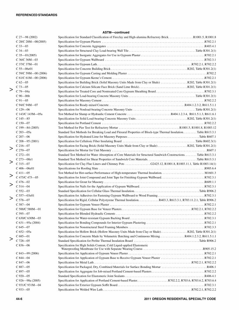
ASTM—continuedC 27—98 (2002) Specification for Standard Classification of Fireclay and High-alumina Refractory Brick. . . . . . . . . . . . . . . . R1001.5, R1001.8
C 28/C 28M—00(2005) Specification for Gypsum Plasters . . . . . . . . . . . . . . . . . . . . . . . . . . . . . . . . . . . . . . . . . . . . . . . . . . . . . . . . . . . . . . . . . .R702.2.1
C 33—03 Specification for Concrete Aggregates . . . . . . . . . . . . . . . . . . . . . . . . . . . . . . . . . . . . . . . . . . . . . . . . . . . . . . . . . . . . . . .R403.4.1
C 34—03 Specification for Structural Clay Load-bearing Wall Tile . . . . . . . . . . . . . . . . . . . . . . . . . . . . . . . . . . . . . . . . . . .Table R301.2(1)
C 35—01(2005) Specification for Inorganic Aggregates for Use in Gypsum Plaster . . . . . . . . . . . . . . . . . . . . . . . . . . . . . . . . . . . . . . . . .R702.2.1
C 36/C 36M—03 Specification for Gypsum Wallboard . . . . . . . . . . . . . . . . . . . . . . . . . . . . . . . . . . . . . . . . . . . . . . . . . . . . . . . . . . . . . . . .R702.3.1
C 37/C 37M—01 Specification for Gypsum Lath. . . . . . . . . . . . . . . . . . . . . . . . . . . . . . . . . . . . . . . . . . . . . . . . . . . . . . . . . . . . .R702.2.1, R702.2.2
C 55—06e01 Specification for Concrete Building Brick . . . . . . . . . . . . . . . . . . . . . . . . . . . . . . . . . . . . . . . . . . . . . . . . .R202, Table R301.2(1)
C 59/C 59M—00 (2006) Specification for Gypsum Casting and Molding Plaster . . . . . . . . . . . . . . . . . . . . . . . . . . . . . . . . . . . . . . . . . . . . . . . . . . .R702.2
C 61/C 61M—00 (2006) Specification for Gypsum Keene’s Cement. . . . . . . . . . . . . . . . . . . . . . . . . . . . . . . . . . . . . . . . . . . . . . . . . . . . . . . . . . . .R702.2.1
C 62—05 Specification for Building Brick (Solid Masonry Units Made from Clay or Shale) . . . . . . . . . . . . . . . . . R202, Table R301.2(1)
C 73—05 Specification for Calcium Silicate Face Brick (Sand Lime Brick) . . . . . . . . . . . . . . . . . . . . . . . . . . . . . . . R202, Table R301.2(1)
C 79—04a Specification for Treated Core and Nontreated Core Gypsum Sheathing Board . . . . . . . . . . . . . . . . . . . . . . . . . . . . . . . R702.3.1
C 90—06b Specification for Load-bearing Concrete Masonry Units . . . . . . . . . . . . . . . . . . . . . . . . . . . . . . . . . . . . . . . . . . .Table R301.2(1)
C 91—05 Specification for Masonry Cement . . . . . . . . . . . . . . . . . . . . . . . . . . . . . . . . . . . . . . . . . . . . . . . . . . . . . . . . . . . . . . . . . .R702.2.2
C 94/C 94M—07 Specification for Ready-mixed Concrete. . . . . . . . . . . . . . . . . . . . . . . . . . . . . . . . . . . . . . . . . . . . . . . . .R404.1.2.3.2, R611.5.1.1
C 129—06 Specification for Nonload-bearing Concrete Masonry Units . . . . . . . . . . . . . . . . . . . . . . . . . . . . . . . . . . . . . . . .Table R301.2(1)
C 143/C 143M—05a Test Method for Slump or Hydraulic Cement Concrete . . . . . . . . . . . . . . . . . . . . . . . . . . . . R404.1.2.3.4, R611.5.1.3, R611.6.1
C 145—85 Specification for Solid Load-bearing Concrete Masonry Units . . . . . . . . . . . . . . . . . . . . . . . . . . . . . . . . . R202, Table R301.2(1)
C 150—07 Specification for Portland Cement . . . . . . . . . . . . . . . . . . . . . . . . . . . . . . . . . . . . . . . . . . . . . . . . . . . . . . . . . . . . . . . . . .R702.2.2
C 199—84 (2005) Test Method for Pier Test for Refractory Mortar . . . . . . . . . . . . . . . . . . . . . . . . . . . . . . . . . . . . . . .R1001.5, R1001.8, R1003.12
C 203—05a Standard Test Methods for Breaking Load and Flexural Properties of Block-type Thermal Insulation. . . . . . . . . Table R613.3.1
C 207—06 Specification for Hydrated Lime for Masonry Purposes . . . . . . . . . . . . . . . . . . . . . . . . . . . . . . . . . . . . . . . . . . . . . .Table R607.1
C 208—95 (2001) Specification for Cellulosic Fiber Insulating Board . . . . . . . . . . . . . . . . . . . . . . . . . . . . . . . . . . . . . . . . . . . . . . .Table R602.3(1)
C 216—07 Specification for Facing Brick (Solid Masonry Units Made from Clay or Shale) . . . . . . . . . . . . . . . . . . . R202, Table R301.2(1)
C 270—07 Specification for Mortar for Unit Masonry . . . . . . . . . . . . . . . . . . . . . . . . . . . . . . . . . . . . . . . . . . . . . . . . . . . . . . . . . . . . .R607.1
C 272—01 Standard Test Method for Water Absorption of Core Materials for Structural Sandwich Constructions. . . . . . . . Table R613.3.1
C 273—00e1 Standard Test Method for Shear Properties of Sandwich Core Materials. . . . . . . . . . . . . . . . . . . . . . . . . . . . . . . . Table R613.3.1
C 315—07 Specification for Clay Flue Liners and Chimney Pots . . . . . . . . . . . . . . . . G2425.12, R1001.8, R1003.11.1, Table R1003.14(1)
C 406—06e01 Specifications for Roofing Slate . . . . . . . . . . . . . . . . . . . . . . . . . . . . . . . . . . . . . . . . . . . . . . . . . . . . . . . . . . . . . . . . . . . .R905.6.4
C 411—05 Test Method for Hot-surface Performance of High-temperature Thermal Insulation. . . . . . . . . . . . . . . . . . . . . . . . . . . . M1601.3
C 475/C 475—05 Specification for Joint Compound and Joint Tape for Finishing Gypsum Wallboard. . . . . . . . . . . . . . . . . . . . . . . . . . . . R702.3.1
C 476—02 Specification for Grout for Masonry . . . . . . . . . . . . . . . . . . . . . . . . . . . . . . . . . . . . . . . . . . . . . . . . . . . . . . . . . . . . . . . . .R609.1.1
C 514—04 Specification for Nails for the Application of Gypsum Wallboard. . . . . . . . . . . . . . . . . . . . . . . . . . . . . . . . . . . . . . . . . .R702.3.1
C 552—03 Standard Specification for Cellular Glass Thermal Insulation. . . . . . . . . . . . . . . . . . . . . . . . . . . . . . . . . . . . . . . . . .Table R906.2
C 557—03e01 Specification for Adhesives for Fastening Gypsum Wallboard to Wood Framing . . . . . . . . . . . . . . . . . . . . . . . . . . . . . . R702.3.1
C 578—07 Specification for Rigid, Cellular Polystyrene Thermal Insulation. . . . . . . . . . . . . R403.3, R613.3.1, R703.11.2.1, Table R906.2
C 587—04 Specification for Gypsum Veneer Plaster . . . . . . . . . . . . . . . . . . . . . . . . . . . . . . . . . . . . . . . . . . . . . . . . . . . . . . . . . . . . .R702.2.1
C 588/C 588M—01 Specification for Gypsum Base for Veneer Plasters . . . . . . . . . . . . . . . . . . . . . . . . . . . . . . . . . . . . . . . . . . . . .R702.2.1, R702.2.2
C 595—07 Specification for Blended Hydraulic Cements . . . . . . . . . . . . . . . . . . . . . . . . . . . . . . . . . . . . . . . . . . . . . . . . . . . . . . . . .R702.2.2
C 630/C 630M—03 Specification for Water-resistant Gypsum Backing Board . . . . . . . . . . . . . . . . . . . . . . . . . . . . . . . . . . . . . . . . . . . . . . . .R702.3.1
C 631—95a (2004) Specification for Bonding Compounds for Interior Gypsum Plastering. . . . . . . . . . . . . . . . . . . . . . . . . . . . . . . . . . . . . .R702.2.1
C 645—07 Specification for Nonstructural Steel Framing Members . . . . . . . . . . . . . . . . . . . . . . . . . . . . . . . . . . . . . . . . . . . . . . . . .R702.3.3
C 652—05a Specification for Hollow Brick (Hollow Masonry Units Made from Clay or Shale). . . . . . . . . . . . . . . . . R202, Table R301.2(1)
C 685—01 Specification for Concrete Made by Volumetric Batching and Continuous Mixing. . . . . . . . . . . . . . . . R404.1.2.3.2, R611.5.1.1
C 728—05 Standard Specification for Perlite Thermal Insulation Board . . . . . . . . . . . . . . . . . . . . . . . . . . . . . . . . . . . . . . . . . .Table R906.2
C 836—06 Specification for High Solids Content, Cold Liquid-applied ElastomericWaterproofing Membrane for Use with Separate Wearing Course. . . . . . . . . . . . . . . . . . . . . . . . . . . . . . . . . . . . . . .R905.15.2
C 843—99 (2006) Specification for Application of Gypsum Veneer Plaster . . . . . . . . . . . . . . . . . . . . . . . . . . . . . . . . . . . . . . . . . . . . . . . . .R702.2.1
C 844—04 Specification for Application of Gypsum Base to Receive Gypsum Veneer Plaster . . . . . . . . . . . . . . . . . . . . . . . . . . . . R702.2.1
C 847—06 Specification for Metal Lath . . . . . . . . . . . . . . . . . . . . . . . . . . . . . . . . . . . . . . . . . . . . . . . . . . . . . . . . . . . . . . .R702.2.1, R702.2.2
C 887—05 Specification for Packaged, Dry, Combined Materials for Surface Bonding Mortar . . . . . . . . . . . . . . . . . . . . . . . . . . . . . R406.1
C 897—05 Specification for Aggregate for Job-mixed Portland Cement-based Plasters . . . . . . . . . . . . . . . . . . . . . . . . . . . . . . . . . .R702.2.2
C 920—05 Standard Specification for Elastomeric Joint Sealants . . . . . . . . . . . . . . . . . . . . . . . . . . . . . . . . . . . . . . . . . . . . . . . . . . .R406.4.1
C 926—98a (2005) Specification for Application of Portland Cement-based Plaster. . . . . . . . . . . . . . . . . . . . R702.2.2, R703.6, R703.6.2, R703.6.4
C 931/C 931M—04 Specification for Exterior Gypsum Soffit Board . . . . . . . . . . . . . . . . . . . . . . . . . . . . . . . . . . . . . . . . . . . . . . . . . . . . . . . .R702.3.1
C 933—05 Specification for Welded Wire Lath . . . . . . . . . . . . . . . . . . . . . . . . . . . . . . . . . . . . . . . . . . . . . . . . . . . . . . . . .R702.2.1, R702.2.2
REFERENCED STANDARDS
44-6 2011 OREGON RESIDENTIAL SPECIALTY CODE
>
>
>
>
>
>
>
6M:\data\CODES\STATE CODES\Oregon\2011\Residential\Final VP\44_Oregon_Res_2011.vpMonday, May 02, 2011 11:56:55 AM
Color profile: Generic CMYK printer profileComposite Default screen

ASTM—continued
C 954—04 Specification for Steel Drill Screws for the Application of Gypsum Panel Products orMetal Plaster Bases to Steel Studs from 0.033 in. (0.84 mm)to 0.112 in. (2.84 mm) in Thickness . . . . . . . . . . . . . . . . . . . . . . . . . . . . . . . . . . . . . .R505.2.4, R603.2.4, R702.3.6, R804.2.4
C 955—06 Specification for Load-bearing (Transverse and Axial) Steel Studs, Runners (Tracks), and Bracing orBridging for Screw Application of Gypsum Panel Products and Metal Plaster Bases. . . . . . . . . . . . . . . . . . . . . . . . . R702.3.3
C 957—06 Specification for High-solids Content, Cold Liquid-applied Elastomeric WaterproofingMembrane for Use with Integral Wearing Surface . . . . . . . . . . . . . . . . . . . . . . . . . . . . . . . . . . . . . . . . . . . . . . . . . . .R905.15.2
C 960—04 Specification for Predecorated Gypsum Board . . . . . . . . . . . . . . . . . . . . . . . . . . . . . . . . . . . . . . . . . . . . . . . . . . . . . . . . .R702.3.1
C 1002—04 Specification for Steel Drill Screws for the Application of Gypsum PanelProducts or Metal Plaster Bases . . . . . . . . . . . . . . . . . . . . . . . . . . . . . . . . . . . . . . . . . . . . . . . . . . . . . . . . . .R702.3.1, R702.3.6
C 1029—05a Specification for Spray-applied Rigid Cellular Polyurethane Thermal Insulation. . . . . . . . . . . . . . . . . . . . . . . . . . . . . R905.14.2
C 1032—06 Specification for Woven Wire Plaster Base . . . . . . . . . . . . . . . . . . . . . . . . . . . . . . . . . . . . . . . . . . . . . . . . . . .R702.2.1, R702.2.2
C 1047—05 Specification for Accessories for Gypsum Wallboard and Gypsum Veneer Base. . . . . . . . . . . . . . R702.2.1, R702.2.2, R702.3.1
C 1063—06 Specification for Installation of Lathing and Furring to Receive Interiorand Exterior Portland Cement-based Plaster . . . . . . . . . . . . . . . . . . . . . . . . . . . . . . . . . . . . . . . . . . . . . . . . . .R702.2.2, R703.6
C 1107—07 Standard Specification for Packaged Dry, Hydraulic-cement Grout (Nonshrink) . . . . . . . . . . . . . . . . . . . . . . . . . . . . . . R402.3.1
C 1116—06 Standard Specification for Fiber-reinforced Concrete and Shotcrete . . . . . . . . . . . . . . . . . . . . . . . . . . . . . . . . . . . . . . . .R402.3.1
C 1167—03 Specification for Clay Roof Tiles . . . . . . . . . . . . . . . . . . . . . . . . . . . . . . . . . . . . . . . . . . . . . . . . . . . . . . . . . . . . . . . . . . .R905.3.4
C 1177/C 1177M—06 Specification for Glass Mat Gypsum Substrate for Use as Sheathing . . . . . . . . . . . . . . . . . . . . . . . . . . . . . . . . . . . . . . .R702.3.1
C 1178/C 1178M—06 Specification for Glass Mat Water-resistant Gypsum Backing Panel . . . . . . . . . . . . . . . . . . . . . . . R702.3.1, R702.3.8, R702.4.2
C 1186—07 Specification for Flat Nonasbestos Fiber Cement Sheets. . . . . . . . . . . . . . . . . . . . . . . . . . . . . . . . . . . . . . .R703.10.1, R703.10.2
C 1261—07 Specification for Firebox Brick for Residential Fireplaces . . . . . . . . . . . . . . . . . . . . . . . . . . . . . . . . . . . . . . . .R1001.5, R1001.8
C 1278/C 1278M—06 Specification for Fiber-reinforced Gypsum Panels . . . . . . . . . . . . . . . . . . . . . . . . . . . . . . . . . . . . .R702.3.1, R702.3.8, R702.4.2
C 1283—07 Practice for Installing Clay Flue Lining. . . . . . . . . . . . . . . . . . . . . . . . . . . . . . . . . . . . . . . . . . . . . . . . . . . . . . . . . . . . . .R1003.12
C 1288—99(2004) Standard Specification for Discrete Nonasbestos Fiber-cement Interior Substrate Sheets. . . . . . . . . . . . . . . . . . . . . . . . R702.4.2
C 1289—07 Standard Specification for Faced Rigid Cellular Polyisocyanurate ThermalInsulation Board . . . . . . . . . . . . . . . . . . . . . . . . . . . . . . . . . . . . . . . . . . . . . . . . . . . . . . . . . . . . . . . .R703.11.2.1, Table R906.2
C 1325—04 Standard Specification for Nonasbestos Fiber-mat Reinforced Cement Interior Substrate Sheets . . . . . . . . . . . . . . . . . R702.4.2
C 1328—05 Specification for Plastic (Stucco) Cement. . . . . . . . . . . . . . . . . . . . . . . . . . . . . . . . . . . . . . . . . . . . . . . . . . . . . . . . . . . . .R702.2.2
C 1395/C 1395M—06a Specification for Gypsum Ceiling Board . . . . . . . . . . . . . . . . . . . . . . . . . . . . . . . . . . . . . . . . . . . . . . . . . . . . . . . . . . . . .R702.3.1
C 1396/C 1396M—06a Specification for Gypsum Board . . . . . . . . . . . . . . . . . . . . . . . . . . . . . . . . . . . . . . . . . . . . .Table R602.3(1), R702.3.1, R702.3.8
C 1492—03 Specification for Concrete Roof Tile. . . . . . . . . . . . . . . . . . . . . . . . . . . . . . . . . . . . . . . . . . . . . . . . . . . . . . . . . . . . . . . . .R905.3.5
C 1513—04 Standard Specification for Steel Tapping Screws for Cold-formedSteel Framing Connections . . . . . . . . . . . . . . . . . . . . . . . . . . . . . . . . . . . . . . . . . . . . .R505.2.4, R603.2.4, R702.3.6, R804.2.4
C 1658/C 1658M—06 Standard Specification for Glass Mat Gypsum Panels . . . . . . . . . . . . . . . . . . . . . . . . . . . . . . . . . . . . . . . . . . . . . . . . . . .R702.3.1
D 41—05 Specification for Asphalt Primer Used in Roofing, Dampproofing and Waterproofing. . . . . . . Table R905.9.2, Table R905.11.2
D 43—00(2006) Specification for Coal Tar Primer Used in Roofing, Dampproofing and Waterproofing . . . . . . . . . . . . . . . . . . . . Table R905.9.2
D 225—04 Specification for Asphalt Shingles (Organic Felt) Surfaced with Mineral Granules . . . . . . . . . . . . . . . . . . . . . . . . . . . . R905.2.4
D 226—06 Specification for Asphalt-saturated (Organic Felt) Used in Roofing and Waterproofing . . . . . . . . . R703.2, R905.2.3, R905.3.3,R905.4.3, R905.5.3, R905.6.3, R905.7.3, R905.8.3, R905.8.4,Table R905.9.2
D 227—03 Specification for Coal Tar Saturated (Organic Felt) Used in Roofing and Waterproofing . . . . . . . . . . . . . . . . . . . Table R905.9.2
D 312—00(2006) Specification for Asphalt Used in Roofing . . . . . . . . . . . . . . . . . . . . . . . . . . . . . . . . . . . . . . . . . . . . . . . . . . . . . . .Table R905.9.2
D 422—63(2002)e01 Test Method for Particle-size Analysis of Soils . . . . . . . . . . . . . . . . . . . . . . . . . . . . . . . . . . . . . . . . . . . . . . . . . . . . . . .R403.1.8.1
D 449—03 Specification for Asphalt Used in Dampproofing and Waterproofing . . . . . . . . . . . . . . . . . . . . . . . . . . . . . . . . . . . . . . . . .R406.2
D 450—07 Specification for Coal-tar Pitch Used in Roofing, Dampproofing and Waterproofing . . . . . . . . . . . . . . . . . . . . . . Table R905.9.2
D 1227—95(2007) Specification for Emulsified Asphalt Used as a ProtectiveCoating for Roofing . . . . . . . . . . . . . . . . . . . . . . . . . . . . . . . . . . . . . . . . . . . . . . .Table R905.9.2, Table R905.11.2, R905.15.2
D 1248—05 Specification for Polyethylene Plastics Extrusion Materials for Wire and Cable . . . . . . . . . . . . . . . . . . . . . . . . . . . . . M1601.1.2
D 1621—04a Standard Test Method for Compressive Properties of Rigid Cellular Plastics . . . . . . . . . . . . . . . . . . . . . . . . . . . . Table R613.3.1
D 1622—03 Standard Test Method for Apparent Density of Rigid Cellular Plastics . . . . . . . . . . . . . . . . . . . . . . . . . . . . . . . . .Table R613.3.1
D 1623—78(1995) Standard Test Method for Tensile and Tensile Adhesion Properties of Rigid Cellular Plastics . . . . . . . . . . . . . . . Table R613.3.1
D 1693—07 Test Method for Environmental Stress-cracking of Ethylene Plastics . . . . . . . . . . . . . . . . . . . . . . . . . . . . . . . . . .Table M2101.1
D 1784—06a Standard Specification for Rigid Poly (Vinyl Chloride) (PVC) Compoundsand Chlorinated Poly (Vinyl Chloride) (CPVC) Compounds . . . . . . . . . . . . . . . . . . . . . . . . . . . . . . . . . . . . . . . . . .M1601.1.2
D 1863—05 Specification for Mineral Aggregate Used in Built-up Roofs. . . . . . . . . . . . . . . . . . . . . . . . . . . . . . . . . . . . . . . . .Table R905.9.2
D 1970—01 Specification for Self-adhering Polymer Modified Bitumen Sheet MaterialsUsed as Steep Roofing Underlayment for Ice Dam Protection . . . . . . . . . . . . . . . . . . . . . . . . . . R905.2.3, R905.2.8, R905.4.3
D 2126—04 Standard Test Method for Response of Rigid Cellular Plastics to Thermal and Humid Aging . . . . . . . . . . . . . . . Table R613.3.1
D 2178—04 Specification for Asphalt Glass Felt Used in Roofing and Waterproofing . . . . . . . . . . . . . . . . . . . . . . . . . . . . . . . Table R905.9.2
REFERENCED STANDARDS
2011 OREGON RESIDENTIAL SPECIALTY CODE 44-7
>
>
>
>
>>>
>
7M:\data\CODES\STATE CODES\Oregon\2011\Residential\Final VP\44_Oregon_Res_2011.vpMonday, May 02, 2011 11:56:55 AM
Color profile: Generic CMYK printer profileComposite Default screen

ASTM—continuedD 2412—02 Test Method for Determination of External Loading Characteristics of Plastic Pipe by
Parallel-plate Loading. . . . . . . . . . . . . . . . . . . . . . . . . . . . . . . . . . . . . . . . . . . . . . . . . . . . . . . . . . . . . . . . . . . . . . . . .M1601.1.2
D 2447—03 Specification for Polyethylene (PE) Plastic Pipe Schedules 40 and 80, Based on Outside Diameter . . . . . . . . . . Table M2101.1
D 2513—07a Specification for Thermoplastic Gas Pressure Pipe, Tubing and Fittings . . . . . . . . . . . . . . . . . . G2414.6, G2414.6.1, G2414.11,G2415.15.2, Table M2101.1, M2104.2.1.3
D 2559—04 Standard Specification for Adhesives for Structural Laminated Wood Products forUse Under Exterior (West Use) Exposure Conditions . . . . . . . . . . . . . . . . . . . . . . . . . . . . . . . . . . . . . . . . . . . . . . . . .R613.3.3
D 2626—04 Specification for Asphalt-saturated and Coated Organic Felt Base Sheet Used in Roofing . . . . . . . . . R905.3.3, Table R905.9.2
D 2683—04 Specification for Socket-type Polyethylene Fittings for OutsideDiameter-controlled Polyethylene Pipe and Tubing . . . . . . . . . . . . . . . . . . . . . . . . . . . . . . . . . . .Table M2101.1, M2104.2.1.1
D 2822—05 Specification for Asphalt Roof Cement. . . . . . . . . . . . . . . . . . . . . . . . . . . . . . . . . . . . . . . . . . . . . . . . . . . . . . . . . .Table R905.9.2
D 2823—05 Specification for Asphalt Roof Coatings. . . . . . . . . . . . . . . . . . . . . . . . . . . . . . . . . . . . . . . . . . . . . . . . . . . . . . . . .Table R905.9.2
D 2824—06 Specification for Aluminum-pigmented Asphalt Roof Coatings, Nonfibered,Asbestos Fibered and Fibered without Asbestos . . . . . . . . . . . . . . . . . . . . . . . . . . . . . . . . . .Table R905.9.2, Table R905.11.2
D 2837—04e01 Test Method for Obtaining Hydrostatic Design Basis for Thermoplastic Pipe Materialsor Pressure Design Basis for Thermoplastic Pipe Products . . . . . . . . . . . . . . . . . . . . . . . . . . . . . . . . . . . . . . . .Table M2101.1
D 2846/D 2846M—06 Specification for Chlorinated Poly (Vinyl Chloride) (CPVC) PlasticHot- and Cold-water Distribution Systems . . . . . . . . . . . . . . . . . . . . . . . . . . . . . . . . . . . . . . . . . . . . . . . . . . . . .Table M2101.1
D 2898—04 Test Methods for Accelerated Weathering of Fire-retardant-treated Wood for Fire Testing . . . . . . . . . . . R802.1.3.4, R802.1.3.6
D 3019—94 (2007) Specification for Lap Cement Used with Asphalt Roll Roofing, Nonfibered,Asbestos Fibered and Nonasbestos Fibered . . . . . . . . . . . . . . . . . . . . . . . . . . . . . . . . . . . . . .Table R905.9.2, Table R905.11.2
D 3035—06 Specification for Polyethylene (PE) Plastic Pipe (DR-PR) Based On Controlled Outside Diameter. . . . . . . . . . . Table M2101.1
D 3161—06 Test Method for Wind Resistance of Asphalt Shingles (Fan Induced Method). . . . . . . . . . . . . . R905.2.4.1, Table R905.2.4.1(2)
D 3201—07 Test Method for Hygroscopic Properties of Fire-retardant Wood and Wood-base Products. . . . . . . . . . . . . . . . . . . . . R802.1.3.7
D 3309—96a (2002) Specification for Polybutylene (PB) Plastic Hot- and Code-water Distribution System . . . . . . . . . . . . . . . . . . . . Table M2101.1
D 3350—06 Specification for Polyethylene Plastic Pipe and Fitting Materials . . . . . . . . . . . . . . . . . . . . . . . . . . . . . . . . . . . . .Table M2101.1
D 3462—07 Specification for Asphalt Shingles Made From Glass Felt and Surfaced with Mineral Granules . . . . . . . . . . . . . . . . . . R905.2.4
D 3468—99 (2006)e01 Specification for Liquid-applied Neoprene and Chlorosulfanated Polyethylene Used inRoofing and Waterproofing . . . . . . . . . . . . . . . . . . . . . . . . . . . . . . . . . . . . . . . . . . . . . . . . . . . . . . . . . . . . . . . . . . . . .R905.15.2
D 3679—06a Specification for Rigid Poly (Vinyl Chloride) (PVC) Siding . . . . . . . . . . . . . . . . . . . . . . . . . . . . . . . . . . .Table R703.4, R703.11
D 3737—07 Practice for Establishing Allowable Properties for Structural GluedLaminated Timber (Glulam) . . . . . . . . . . . . . . . . . . . . . . . . . . . . . . . . . . . . . . . . . . . . . . . . . . . .R502.1.5, R602.1.2, R802.1.4
D 3747—79 (2007) Specification for Emulsified Asphalt Adhesive for Adhering Roof Insulation . . . . . . . . . . . . . Table R905.9.2, Table R905.11.2
D 3909—97b (2004)e01 Specification for Asphalt Roll Roofing (Glass Felt) Surfaced with Mineral Granules. . . . . . . . . . . . . . . . . . . . . . . . . R905.2.8.2,R905.5.4, Table R905.9.2
D 3957—06 Standard Practices for Establishing Stress Grades for StructuralMembers Used in Log Buildings . . . . . . . . . . . . . . . . . . . . . . . . . . . . . . . . . . . . . . . . . . . . . . . . .R502.1.6, R602.1.3, R802.1.5
D 4022—07 Specification for Coal Tar Roof Cement, Asbestos Containing . . . . . . . . . . . . . . . . . . . . . . . . . . . . . . . . . . . . . . .Table R905.9.2
D 4318—05 Test Methods for Liquid Limit, Plastic Limit and Plasticity Index of Soils . . . . . . . . . . . . . . . . . . . . . . . . . . . . . . . . .R403.1.8.1
D 4434—06 Specification for Poly (Vinyl Chloride) Sheet Roofing. . . . . . . . . . . . . . . . . . . . . . . . . . . . . . . . . . . . . . . . . . . . . . . . . .R905.13.2
D 4479—07 Specification for Asphalt Roof Coatings-asbestos-free. . . . . . . . . . . . . . . . . . . . . . . . . . . . . . . . . . . . . . . . . . . . . .Table R905.9.2
D 4586—00 Specification for Asphalt Roof Cement-asbestos-free . . . . . . . . . . . . . . . . . . . . . . . . . . . . . . . . . . . . . . . . . . . . . .Table R905.9.2
D 4601—04 Specification for Asphalt-coated Glass Fiber Base Sheet Used in Roofing . . . . . . . . . . . . . . . . . . . . . . . . . . . . . . Table R905.9.2
D 4637—04 Specification for EPDM Sheet Used in Single-ply Roof Membrane . . . . . . . . . . . . . . . . . . . . . . . . . . . . . . . . . . . . . . .R905.12.2
D 4829—07 Test Method for Expansion Index of Soils . . . . . . . . . . . . . . . . . . . . . . . . . . . . . . . . . . . . . . . . . . . . . . . . . . . . . . . . . . .R403.1.8.1
D 4869—05e01 Specification for Asphalt-saturated (Organic Felt) UnderlaymentUsed in Steep Slope Roofing . . . . . . . . . . . . . . . . . . . . . . . . . . . R905.2.3, R905.4.3, R905.5.3, R905.6.3, R905.7.3, R905.8.3
D 4897—01 Specification for Asphalt Coated Glass-fiber Venting Base Sheet Used in Roofing . . . . . . . . . . . . . . . . . . . . . . . Table R905.9.2
D 4990—97a (2005)e01 Specification for Coal Tar Glass Felt Used in Roofing and Waterproofing . . . . . . . . . . . . . . . . . . . . . . . . . . . . . . Table R905.9.2
D 5019—07 Specification for Reinforced Nonvulcanized Polymeric Sheet Used in Roofing Membrane . . . . . . . . . . . . . . . . . . . . . R905.12.2
D 5055—05 Specification for Establishing and Monitoring Structural Capacities of Prefabricated Wood I-joists . . . . . . . . . . . . . . . R502.1.4
D 5516—03 Test Method for Evaluating the Flexural Properties of Fire-retardant-treated SoftwoodPlywood Exposed to the Elevated Temperatures. . . . . . . . . . . . . . . . . . . . . . . . . . . . . . . . . . . . . . . . . . . . . . . . . . .R802.1.3.5.1
D 5643—06 Specification for Coal Tar Roof Cement Asbestos-free . . . . . . . . . . . . . . . . . . . . . . . . . . . . . . . . . . . . . . . . . . . . .Table R905.9.2
D 5664—02 Test Methods For Evaluating the Effects of Fire-retardant Treatmentsand Elevated Temperatures on Strength Properties of Fire-retardant-treated Lumber . . . . . . . . . . . . . . . . . . . . . . R802.1.3.5.2
D 5665—99a(2006) Specification for Thermoplastic Fabrics Used in Cold-applied Roofing and Waterproofing . . . . . . . . . . . . . . . . . Table R905.9.2
D 5726—98(2005) Specification for Thermoplastic Fabrics Used in Hot-applied Roofing and Waterproofing . . . . . . . . . . . . . . . . . . Table R905.9.2
D 6083—05e01 Specification for Liquid-applied Acrylic Coating Used in Roofing . . . . . . . . . . . . Table R905.9.2, Table R905.11.2, R905.15.2
D 6162—00a Specification for Styrene Butadiene Styrene (SBS) Modified Bituminous Sheet MaterialsUsing a Combination of Polyester and Glass Fiber Reinforcements . . . . . . . . . . . . . . . . . . . . . . . . . . . . . . . . Table R905.11.2
REFERENCED STANDARDS
44-8 2011 OREGON RESIDENTIAL SPECIALTY CODE
>
>
>>
>>>
>
>
>
>
>
8M:\data\CODES\STATE CODES\Oregon\2011\Residential\Final VP\44_Oregon_Res_2011.vpMonday, May 02, 2011 11:56:55 AM
Color profile: Generic CMYK printer profileComposite Default screen

ASTM—continuedD 6163—00e01 Specification for Styrene Butadiene Styrene (SBS) Modified Bituminous Sheet Materials
Using Glass Fiber Reinforcements . . . . . . . . . . . . . . . . . . . . . . . . . . . . . . . . . . . . . . . . . . . . . . . . . . . . . . . . . .Table R905.11.2D 6164—05 Specification for Styrene Butadiene Styrene (SBS) Modified Bituminous Sheet Materials
Using Polyester Reinforcements . . . . . . . . . . . . . . . . . . . . . . . . . . . . . . . . . . . . . . . . . . . . . . . . . . . . . . . . . . . .Table R905.11.2D 6222—02e01 Specification for Atactic Polypropelene (APP) Modified Bituminous Sheet Materials
Using Polyester Reinforcement . . . . . . . . . . . . . . . . . . . . . . . . . . . . . . . . . . . . . . . . . . . . . . . . . . . . . . . . . . . . .Table R905.11.2D 6223—02e01 Specification for Atactic Polypropelene (APP) Modified Bituminous Sheet Materials
Using a Combination of Polyester and Glass Fiber Reinforcement . . . . . . . . . . . . . . . . . . . . . . . . . . . . . . . . .Table R905.11.2D 6298—05 Specification for Fiberglass-reinforced Styrene Butadiene Styrene (SBS) Modified
Bituminous Sheets with a Factory Applied Metal Surface . . . . . . . . . . . . . . . . . . . . . . . . . . . . . . . . . . . . . . . .Table R905.11.2D 6305—02e01 Practice for Calculating Bending Strength Design Adjustment Factors
for Fire-retardant-treated Plywood Roof Sheathing . . . . . . . . . . . . . . . . . . . . . . . . . . . . . . . . . . . . . . . . . . . . . . . .R802.1.3.5.1D 6380—03 Standard Specification for Asphalt Roll Roofing (Organic Felt) . . . . . . . . . . . . . . . . . . . . . . . . . R905.2.8.2, R905.3.3, R905.5.4D 6694—07 Standard Specification Liquid-applied Silicone Coating Used in Spray Polurethane Foam Roofing . . . . . . . . . . . . . . R905.15.2D 6754—02 Standard Specification for Ketone-ethylene-ester-based Sheet Roofing. . . . . . . . . . . . . . . . . . . . . . . . . . . . . . . . . . . . .R905.13.2D 6757—07 Standard Specification for Inorganic Underlayment for Use with Steep Slope Roofing Products. . . . . . . . . . . . . . . . . . R905.2.3D 6841—03 Standard Practice for Calculating Design Value Treatment Adjustment Factors
for Fire-retardant-treated Lumber . . . . . . . . . . . . . . . . . . . . . . . . . . . . . . . . . . . . . . . . . . . . . . . . . . . . . . . . . . . . . .R802.1.3.5.2D 6878—06a Standard Specification for Thermoplastic-polyolefin-based Sheet Roofing. . . . . . . . . . . . . . . . . . . . . . . . . . . . . . . . . .R905.13.2D 6947—07 Standard Specification for Liquid Applied Moisture Cured Polyurethane Coating
Used in Spray Polyurethane Foam Roofing System . . . . . . . . . . . . . . . . . . . . . . . . . . . . . . . . . . . . . . . . . . . . . . . . . .R905.15.2D 7032—07 Standard Specification for Establishing Perfomance Ratings for Wood-plastic Composite
Deck Boards and Guardrail Systems (Guards or Handrails) . . . . . . . . . . . . . . . . . . . . . . . . . . . . . . . . . . . . . . . . . . . . . .R317.4D 7158—07 Standard Test Method for Wind Resistance of Sealed Asphalt Shingles (Uplift Force/
Uplift Resistance Method) . . . . . . . . . . . . . . . . . . . . . . . . . . . . . . . . . . . . . . . . . . . . . . . . . . . .R905.2.4.1, Table R905.2.4.1(1)E 84—07 Test Method for Surface Burning Characteristics of Building Materials. . . . . M1601.3, M1601.5.2, R202, R302.9.3, R302.9.4,
R302.10.1, R302.10.2, R316.3, R316.5.9, R316.5.11, R802.1.3E 90—04 Test Method for Laboratory Measurement of Airborne Sound Transmission
Loss of Building Partitions and Elements . . . . . . . . . . . . . . . . . . . . . . . . . . . . . . . . . . . . . . . . . . . . . . . . . .AK102, AK102,1.1E 96/E 96M—05 Test Method for Water Vapor Transmission of Materials. . . . . . . . . . . . . . . . . . . . . M1411.5, M1601.4.5, R202, Table R613.3.1E 108—07a Test Methods for Fire Tests of Roof Coverings . . . . . . . . . . . . . . . . . . . . . . . . . . . . . . . . . . . . . . . . . . . . . . . . . . . . . . . . . .R902.1E 119—07 Test Methods for Fire Tests of Building Construction and Materials . . . . . . . Table R302.1, R302.2, R302.3, R302.4.1, R316.4E 136—04 Test Method for Behavior of Materials in a Vertical Tube Furnace at 750°C. . . . . . . . . . . . . . . . . . . . . . . . . . . . . R202, R302.11E 283-04 Test Method of Determining the Rate of Air Leakage through Exterior Windows, Curtain Walls
mand Doors Under Specified Pressure Difference Across the Specimen. . . . . . . . . . . . . . . . . . . . . . . . . . . . . . . . . . . .N1104.8.1E 330—02 Test Method for Structural Performance of Exterior Windows, Curtain Walls and
Doors by Uniform Static Air Pressure Difference . . . . . . . . . . . . . . . . . . . . . . . . . . . . . . . . . . . . . . .R612.7, R612.8, R703.1.2E 331—00 Test Method for Water Penetration of Exterior Windows, Skylights, Doors
and Curtain Walls by Uniform Static Air Pressure Difference . . . . . . . . . . . . . . . . . . . . . . . . . . . . . . . . . . . . . . . . . . .R703.1.1E 492—04 Specification for Laboratory Measurement of Impact Sound Transmission through
Floor-ceiling Assemblies Using the Tapping Machine . . . . . . . . . . . . . . . . . . . . . . . . . . . . . . . . . . . . . . . . . . . . . . . . . .AK103E 814—06 Test Method for Fire Tests of Through-penetration Firestops . . . . . . . . . . . . . . . . . . . . . . . . . . . . . . . . . . . . . . . . . . . .R302.4.1.2E 970—00 Test Method for Critical Radiant Flux of Exposed Attic Floor Insulation
Using a Radiant Heat Energy Source . . . . . . . . . . . . . . . . . . . . . . . . . . . . . . . . . . . . . . . . . . . . . . . . . . . . . . . . . . . . .R302.10.5E 1509—04 Standard Specification for Room Heaters, Pellet Fuel-burning Type . . . . . . . . . . . . . . . . . . . . . . . . . . . . . . . . . . . . . . . .M1410.1E 1602—03 Guide for Construction of Solid Fuel Burning Masonry Heaters . . . . . . . . . . . . . . . . . . . . . . . . . . . . . . . . . . . . . . . . . . .R1002.2E 1886—06 Test Method for Performance of Exterior Windows, Curtain Walls, Doors and Storm Shutters
Impacted by Missles and Exposed to Cyclic Pressure Differentials . . . . . . . . . . . . . . . . . . . . . . . . . . . . . R301.2.1.2, R612.9.1E 1996—06 Standard Specification for Performance of Exterior Windows, Curtain Walls, Doors
and Impact Protective Systems Impacted by Windborne Debris in Hurricanes . . . . . . . . . . . . . . . . . . . . R301.2.1.2, R612.9.1E 2178—03 Standard Test Method for Air Permeance of Building Materials . . . . . . . . . . . . . . . . . . . . . . . . . . . . . . . . . . . . . . . . . . . . . .R202E 2231—04 Standard Practice for Specimen Preparation and Mounting of Pipe and Duct
Insulation Materials to Assess Surface Burning Characteristics. . . . . . . . . . . . . . . . . . . . . . . . . . . . . . . . . . . . . . . . . .M1601.3E 2273—03 Standard Test Method for Determining the Drainage Efficiency of Exterior Insulation
and Finish Systems (EIFS) Clad Wall Assemblies . . . . . . . . . . . . . . . . . . . . . . . . . . . . . . . . . . . . . . . . . . . . . . . . . . . .R703.9.2E 2568—07 Standard Specification for PB Exterior Insulation and Finish Systems (EIFS) . . . . . . . . . . . . . . . . . . . . . . . . R703.9.1, R703.9.2E 2570—07 Standard Test Methods for Evaluating Water-resistive Barrier (WRB) Coatings Used Under
Exterior Insulation and Finish Systems (EIFS) or EIFS with Drainage . . . . . . . . . . . . . . . . . . . . . . . . . . . . . . . . . .R703.9.2.1F 876—06 Specification for Cross-linked Polyethylene (PEX) Tubing . . . . . . . . . . . . . . . . . . . . . . . . . . . . . . . . . . . . . . . . . .Table M2101.1F 877—07 Specification for Cross-linked Polyethylene (PEX) Plastic Hot- and Cold-water Distribution Systems . . . . . . . . Table M2101.1F 1055—98(2006) Specification for Electrofusion Type Polyethylene Fittings
for Outside Diameter Controlled Polyethylene Pipe and Fittings. . . . . . . . . . . . . . . . . . . . . . . . . Table M2101.1, M2104.2.1.2F 1281—07 Specification for Cross-linked Polyethylene/Aluminum/Cross-linked
Polyethylene (PEX-AL-PEX) Pressure Pipe . . . . . . . . . . . . . . . . . . . . . . . . . . . . . . . . . . . . . . . . . . . . . . . . . . . .Table M2101.1F 1282—06 Specification for Polyethylene/Aluminum/Polyethylene (PE-AL-PE) Composite Pressure Pipe . . . . . . . . . . . . . Table M2101.1
REFERENCED STANDARDS
2011 OREGON RESIDENTIAL SPECIALTY CODE 44-9
>>>>
>>
9M:\data\CODES\STATE CODES\Oregon\2011\Residential\Final VP\44_Oregon_Res_2011.vpFriday, May 13, 2011 12:37:51 PM
Color profile: Generic CMYK printer profileComposite Default screen

ASTM—continuedF 1346—91(2003) Performance Specification for Safety Covers and Labeling Requirements
for All Covers for Swimming Pools, Spas and Hot Tubs . . . . . . . . . . . . . . . . . . . . . . . . . . . . . . . . . . . . . . .AG105.2, AG105.5
F 1554—04e1 Specification for Anchor Bolts, Steel, 36, 55 and 105-ksi Yield Strength. . . . . . . . . . . . . . . . . . . . . . . . . . . . . . . . . . .R611.5.2.2
F 1667—05 Specification for Driven Fasteners, Nails, Spikes and Staples . . . . . . . . . . . . . . . . . . . . . . . . . . . . . . . . .Table R703.4, R905.2.5
F 1807—07 Specification for Metal Insert Fittings Utilizing a Copper Crimp Ring for SDR9Cross-linked Polyethylene (PEX) Tubing . . . . . . . . . . . . . . . . . . . . . . . . . . . . . . . . . . . . . . . . . . . . . . . . . . . . . .Table M2101.1
F 1960—07 Specification for Cold Expansion Fittings with PEX Reinforcing Rings for Usewith Cross-linked Polyethylene (PEX) Tubing . . . . . . . . . . . . . . . . . . . . . . . . . . . . . . . . . . . . . . . . . . . . . . . . . .Table M2101.1
F 1973—05 Standard Specification for Factory Assembled Anodeless Risers and Transition Fittingsin Polyethylene (PE) and Polyamide 11 (PA 11) Fuel Gas Distribution Systems . . . . . . . . . . . . . . . . . . . . . . . . . . G2415.15.2
F 2090—01A(2007) Specification for Window Fall Prevention Devices—with Emergency Escape (Egress)Release Mechanisms. . . . . . . . . . . . . . . . . . . . . . . . . . . . . . . . . . . . . . . . . . . . . . . . . . . . . . . . . . . . . . . . . . . . . .R612.2, R612.3
F 2098—04e1 Standard Specification for Stainless Steel Clamps for SDR9 PEX Tubing to Metal Insert Fittings . . . . . . . . . . . Table M2101.1
F 2389—06 Standard for Pressure-rated Polypropylene (PP) Piping Systems . . . . . . . . . . . . . . . . . . . . . . . . . . . . . . . . . . . . . .Table M2101.1
F 2623—07 Standard Specification for Polyethylene of Raised Temperature (PE-RT) SDRG Tubing . . . . . . . . . . . . . . . . . . . Table M2101.1
American Wood Protection AssociationP.O. Box 361784Birmingham, AL 35236-1784AWPA
Standard Referencedreference in codenumber Title section number
C1—03 All Timber Products—Preservative Treatment by Pressure Processes . . . . . . . . . . . . . . . . . . . . . . . . . . . . . . . . . . . . . . . .R902.2
M4—06 Standard for the Care of Preservative-treated Wood Products . . . . . . . . . . . . . . . . . . . . . . . . . . . . . . . . . . . . .R317.1.1, R318.1.2
U1—07 USE CATEGORY SYSTEM: User Specification for Treated WoodExcept Section 6 Commodity Specification H . . . . . . . . . . . . . . . . . . . . R317.1, R322.1.8, R402.1.2, R504.3, Table R905.8.5
Canadian General Standards BoardPlace du Portage 111, 6B111 Laurier StreetGatineau, Quebec, Canada KIA 1G6CGSB
Standard Referencedreference in codenumber Title section number
37-GP—52M—(1984) Roofing and Waterproofing Membrane, Sheet Applied, Elastomeric. . . . . . . . . . . . . . . . . . . . . . . . . . . . . . . . . . . . . . .R905.12.2
37-GP—56M—(1980) Membrane, Modified Bituminous, Prefabricated and Reinforced for Roofing—with December 1985 Amendment. . . . . . . . . . . . . . . . . . . . . . . . . . . . . . . . . . . . . . . . . . . . . . . . . . . . . . . . .Table R905.11.2
CAN/CGSB-37.54—95 Polyvinyl Chloride Roofing and Waterproofing Membrane . . . . . . . . . . . . . . . . . . . . . . . . . . . . . . . . . . . . . . . . . . . . . .R905.13.2
Composite Panel Association19465 Deerfield Avenue, Suite 306Leesburg, VA 20176CPA
Standard Referencedreference in codenumber Title section number
ANSI A135.4—04 Basic Hardboard. . . . . . . . . . . . . . . . . . . . . . . . . . . . . . . . . . . . . . . . . . . . . . . . . . . . . . . . . . . . . . . . . . . . . . . . . . .Table R602.3(2)
ANSI A135.5—04 Prefinished Hardboard Paneling . . . . . . . . . . . . . . . . . . . . . . . . . . . . . . . . . . . . . . . . . . . . . . . . . . . . . . . . . . . . . . . . . . . . . .R702.5
ANSI A135.6—98 Hardboard Siding . . . . . . . . . . . . . . . . . . . . . . . . . . . . . . . . . . . . . . . . . . . . . . . . . . . . . . . . . . . . . . . . . . . . . . . . . . . .Table R703.4
Consumer Product Safety Commission4330 East West HighwayBethesda, MD 20814-4408CPSC
Standard Referencedreference in codenumber Title section number
16 CFR Part 1201—(1977) Safety Standard for Architectural Glazing . . . . . . . . . . . . . . . . . . . . . . . . . . . . . . . . . . . . . . . . . . . . . . . . . . . .R308.1.1, R308.3.1
16 CFR Part 1209—(1979) Interim Safety Standard for Cellulose Insulation . . . . . . . . . . . . . . . . . . . . . . . . . . . . . . . . . . . . . . . . . . . . . . . . . . . . . .R302.10.3
16 CFR Part 1404—(1979) Cellulose Insulation . . . . . . . . . . . . . . . . . . . . . . . . . . . . . . . . . . . . . . . . . . . . . . . . . . . . . . . . . . . . . . . . . . . . . . . . . . . . .R302.10.3
REFERENCED STANDARDS
44-10 2011 OREGON RESIDENTIAL SPECIALTY CODE
>
>
>
>
>
>
10M:\data\CODES\STATE CODES\Oregon\2011\Residential\Final VP\44_Oregon_Res_2011.vpMonday, May 02, 2011 11:56:56 AM
Color profile: Generic CMYK printer profileComposite Default screen
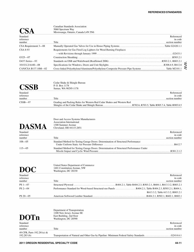
Canadian Standards Association5060 Spectrum WayMississauga, Ontario, Canada L4N 5N6CSA
Standard Referencedreference in codenumber Title section number
CSA Requirement 3—88 Manually Operated Gas Valves for Use in House Piping Systems. . . . . . . . . . . . . . . . . . . . . . . . . . . . . . . . . . . .Table G2420.1.1
CSA 8-93 Requirements for Gas Fired Log Lighters for Wood Burning Fireplaces
—with Revisions through January 1999 . . . . . . . . . . . . . . . . . . . . . . . . . . . . . . . . . . . . . . . . . . . . . . . . . . . . . . . . . . . .G2433.1
O325—07 Construction Sheathing . . . . . . . . . . . . . . . . . . . . . . . . . . . . . . . . . . . . . . . . . . . . . . . . . . . . . . . . . . . . . . . . . . . . . . . . . . .R503.2.1
O437-Series—93 Standards on OSB and Waferboard (Reaffirmed 2006) . . . . . . . . . . . . . . . . . . . . . . . . . . . . . . . . . . . . . . . . . .R503.2.1, R803.2.1
101/I.S.2/A440—08 Specifications for Windows, Doors and Unit Skylights . . . . . . . . . . . . . . . . . . . . . . . . . . . . . . . . . . . . . . . . . . .R308.6.9, R612.6
CAN/CSA B137.10M—02 Cross-linked Polyethylene/Aluminum/Polyethylene Composite Pressure Pipe Systems . . . . . . . . . . . . . . . . . . . Table M2101.1
Cedar Shake & Shingle BureauP. O. Box 1178Sumas, WA 98295-1178CSSB
Standard Referencedreference in codenumber Title section number
CSSB—97 Grading and Packing Rules for Western Red Cedar Shakes and Western RedShingles of the Cedar Shake and Shingle Bureau . . . . . . . . . . . . . . . . . . . . . . . R702.6, R703.5, Table R905.7.4, Table R905.8.5
Door and Access Systems ManufacturersAssociation International1300 Summer AvenueCleveland, OH 44115-2851DASMA
Standard Referencedreference in codenumber Title section number
108—05 Standard Method for Testing Garage Doors: Determination of Structural PerformanceUnder Uniform Static Air Pressure Difference . . . . . . . . . . . . . . . . . . . . . . . . . . . . . . . . . . . . . . . . . . . . . . . . . . . . . . . .R612.7
115—05 Standard Method for Testing Garage Doors: Determination of Structural Performance UnderMissile Impact and Cyclic Wind Pressure . . . . . . . . . . . . . . . . . . . . . . . . . . . . . . . . . . . . . . . . . . . . . . . . . . . . . . . . .R301.2.1.2
United States Department of Commerce1401 Constitution Avenue, NWWashington, DC 20230DOC
Standard Referencedreference in codenumber Title section number
PS 1—07 Structural Plywood . . . . . . . . . . . . . . . . . . . . . . . . . . . . . . . . . R404.2.1, Table R404.2.3, R503.2.1, R604.1, R613.3.2, R803.2.1
PS 2—04 Performance Standard for Wood-based Structural-use Panels . . . . . . . . . . . . . . . . R404.2.1, Table R404.2.3, R503.2.1, R604.1,
R613.3.2, Table 613.3.2, R803.2.1
PS 20—05 American Softwood Lumber Standard. . . . . . . . . . . . . . . . . . . . . . . . . . . . . . . . . . . . . . . . . . .R404.2.1, R502.1, R602.1, R802.1
Department of Transportation1200 New Jersey Avenue SEEast Building, 2nd floorWashington, DC 20590DOTn
Standard Referencedreference in codenumber Title section number
49 CFR, Parts 192.281(e) &192.283 (b) Transportation of Natural and Other Gas by Pipeline: Minimum Federal Safety Standards . . . . . . . . . . . . . . . . . . . . . G2414.6.1
REFERENCED STANDARDS
2011 OREGON RESIDENTIAL SPECIALTY CODE 44-11
>>>>
11M:\data\CODES\STATE CODES\Oregon\2011\Residential\Final VP\44_Oregon_Res_2011.vpFriday, May 13, 2011 12:38:39 PM
Color profile: Generic CMYK printer profileComposite Default screen
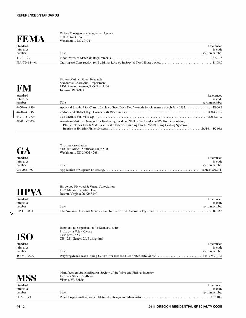
Federal Emergency Management Agency500 C Street, SWWashington, DC 20472FEMA
Standard Referencedreference in codenumber Title section number
TB-2—93 Flood-resistant Materials Requirements . . . . . . . . . . . . . . . . . . . . . . . . . . . . . . . . . . . . . . . . . . . . . . . . . . . . . . . . . . . . . .R322.1.8
FIA-TB-11—01 Crawlspace Construction for Buildings Located in Special Flood Hazard Area. . . . . . . . . . . . . . . . . . . . . . . . . . . . . . . . .R408.7
Factory Mutual Global ResearchStandards Laboratories Department1301 Atwood Avenue, P. O. Box 7500Johnson, RI 02919FM
Standard Referencedreference in codenumber Title section number
4450—(1989) Approval Standard for Class 1 Insulated Steel Deck Roofs—with Supplements through July 1992. . . . . . . . . . . . . . . . . R906.1
4470—(1986) 25-foot and 50-foot High Corner Tests (Section 5.4). . . . . . . . . . . . . . . . . . . . . . . . . . . . . . . . . . . . . . . . . . . . . . . . . . .R314.2.1.2
4471—(1995) Test Method For Wind Up-lift . . . . . . . . . . . . . . . . . . . . . . . . . . . . . . . . . . . . . . . . . . . . . . . . . . . . . . . . . . . . . . . . . . . .R314.2.1.2
4880—(2005) American National Standard for Evaluating Insulated Wall or Wall and Roof/Ceiling Assemblies,Plastic Interior Finish Materials, Plastic Exterior Building Panels, Wall/Ceiling Coating Systems,Interior or Exterior Finish Systems. . . . . . . . . . . . . . . . . . . . . . . . . . . . . . . . . . . . . . . . . . . . . . . . . . . . . . . . . . .R316.4, R316.6
Gypsum Association810 First Street, Northeast, Suite 510Washington, DC 20002-4268GA
Standard Referencedreference in codenumber Title section number
GA-253—07 Application of Gypsum Sheathing. . . . . . . . . . . . . . . . . . . . . . . . . . . . . . . . . . . . . . . . . . . . . . . . . . . . . . . . . . . . .Table R602.3(1)
Hardwood Plywood & Veneer Association1825 Michael Faraday DriveReston, Virginia 20190-5350HPVA
Standard Referencedreference in codenumber Title section number
HP-1—2004 The American National Standard for Hardwood and Decorative Plywood . . . . . . . . . . . . . . . . . . . . . . . . . . . . . . . . . . . . .R702.5
International Organization for Standardization1, ch. de la Voie - CreuseCase postale 56CH-1211 Geneva 20, SwitzerlandISO
Standard Referencedreference in codenumber Title section number
15874—2002 Polypropylene Plastic Piping Systems for Hot and Cold Water Installations . . . . . . . . . . . . . . . . . . . . . . . . . . . . . Table M2101.1
Manufacturers Standardization Society of the Valve and Fittings Industry127 Park Street, NortheastVienna, VA 22180MSS
Standard Referencedreference in codenumber Title section number
SP-58—93 Pipe Hangers and Supports—Materials, Design and Manufacture . . . . . . . . . . . . . . . . . . . . . . . . . . . . . . . . . . . . . . . . . .G2418.2
REFERENCED STANDARDS
44-12 2011 OREGON RESIDENTIAL SPECIALTY CODE
>
12M:\data\CODES\STATE CODES\Oregon\2011\Residential\Final VP\44_Oregon_Res_2011.vpMonday, May 02, 2011 11:56:56 AM
Color profile: Generic CMYK printer profileComposite Default screen

North American Insulation Manufacturers Association44 Canal Center Plaza, Suite 310Alexandria, VA 22314NAIMA
Standard Referencedreference in codenumber Title section number
AH 116—02 Fibrous Glass Duct Construction Standards, Fifth Edition . . . . . . . . . . . . . . . . . . . . . . . . . . . . . . . . . . . . . . . . . . . . . .M1601.1.1
National Concrete Masonry Association13750 Sunrise Valley DriveHerndon, VA 20171-4662NCMA
Standard Referencedreference in codenumber Title section number
TR 68-A—75 Design and Construction of Plain and Reinforced Concrete Masonryand Basement and Foundation Walls. . . . . . . . . . . . . . . . . . . . . . . . . . . . . . . . . . . . . . . . . . . . . . . . . . . . . . . . . . . . . . .R404.1.1
National Fire Protection Association1 Batterymarch ParkQuincy, MA 02269NFPA
Standard Referencedreference in codenumber Title section number
13—07 Installation of Sprinkler Systems . . . . . . . . . . . . . . . . . . . . . . . . . . . . . . . . . . . . . . . . . . . . . . . . . . . . . . . . . . . . . . . . . . . . .R302.3
31—06 Installation of Oil-burning Equipment. . . . . . . . . . . . . . . . . . . . . . . . . . . . . . . . . . . . . . . . . . . . . . . . . . . . . .M1801.3.1, M1805.3
37—98 Standard For Installation And Use of Stationary Combustion Engines and Gas Turbines . . . . . . . . . . . . . . . . . . . . . . . . G2439.1
54—99 National Fuel Gas Code . . . . . . . . . . . . . . . . . . . . . . . . . . . . . . . . . . . . . . . . . . . . . . . . . . . . . . . . . . . . . . . . . . . . . . . . .G2417.4.1
58—08 Liquefied Petroleum Gas Code . . . . . . . . . . . . . . . . . . . . . . . . . . . . . . . . . . . . . . . . . . . . . . . . . . . . . . . . . . . .G2412.2, G2414.6.2
72—07 National Fire Alarm Code. . . . . . . . . . . . . . . . . . . . . . . . . . . . . . . . . . . . . . . . . . . . . . . . . . . . . . . . . . . . . . . . . . . .R314.1, R314.2
85—07 Boiler and Construction Systems Hazards Code . . . . . . . . . . . . . . . . . . . . . . . . . . . . . . . . . . . . . . . . . . . . . . . . . . . . . . . .G2452.1
211—06 Chimneys, Fireplaces, Vents and Solid Fuel Burning Appliances. . . . . . . . . . . . . . . . . . . . . . . . . . . . . . . . G2427.5.5.1, R1002.5
259—03 Test Method for Potential Heat of Building Materials . . . . . . . . . . . . . . . . . . . . . . . . . . . . . . . . . . . . . . . . . . . .R316.5.7, 316.5.8
286—06 Standard Methods of Fire Tests for Evaluating Contribution of Walland Ceiling Interior Finish to Room Fire Growth. . . . . . . . . . . . . . . . . . . . . . . . . . . . . . . R302.9.4, R316.4, R316.5.8, R316.6
501—05 Standard on Manufactured Housing. . . . . . . . . . . . . . . . . . . . . . . . . . . . . . . . . . . . . . . . . . . . . . . . . . . . . . . . . . . . . .R202, AE201
853—07 Standard for the Installation of Stationary Fuel Cell Power Systems . . . . . . . . . . . . . . . . . . . . . . . . . . . . . . . . . . . . . . . .M1903.1
Portland Cement Association5420 Old Orchard RoadSkokie, IL 60077PCA
Standard Referencedreference in codenumber Title section number
100—07 Prescriptive Design of Exterior Concrete Walls for One- and Two-family Dwellings(Pub. No. EB241) . . . . . . . . . . . . . . . . . . . . . . . . . . . . . . . . . . . . . . . . . . . . . . . . . . . . . .R404.1.2, R404.1.2.2.1, R404.1.2.2.2,
R404.1.2.4, R404.1.4.2, R611.1, R611.2, R611.9.2, R611.9.3
Sheet Metal & Air Conditioning Contractors National Assoc. Inc.4021 Lafayette Center RoadChantilly, VA 22021SMACNA
Standard Referencedreference in codenumber Title section number
SMACNA—03 Fibrous Glass Duct Construction Standards (2003) . . . . . . . . . . . . . . . . . . . . . . . . . . . . . . . . . . . . . . . . . . . . . . . . . . .M1601.1.1
REFERENCED STANDARDS
2011 OREGON RESIDENTIAL SPECIALTY CODE 44-13
>
>
>
13M:\data\CODES\STATE CODES\Oregon\2011\Residential\Final VP\44_Oregon_Res_2011.vpMonday, May 02, 2011 11:56:56 AM
Color profile: Generic CMYK printer profileComposite Default screen

The Masonry Society3970 Broadway, Suite 201-DBoulder, CO 80304TMS
Standard Referencedreference in codenumber Title section number302—07 Standard Method for Determining the Sound Transmission Class Rating for Masonry Walls . . . . . . . . . . . . . . . . . . . AK102.1.1402—08 Building Code Requirements for Masonry Structures . . . . . . . . . . . . . . R404.1.1, R606.1, R606.1.1, R606.11.2.2.2, R606.12.1,
R606.12.2.3.1, R606.12.2.3.2, R606.12.3.1, Table R703.4602—08 Specification for Masonry Structures . . . . . . . . . . . . . . . . . . . . . . . . . . . R404.1.1, R606.1, R606.1.1, R606.12.1, R606.12.2.3.1,
R606.12.2.3.2, R606.12.3.1, Table R703.4
Truss Plate Institute583 D’Onofrio Drive, Suite 200Madison, WI 53719TPI
Standard Referencedreference in codenumber Title section numberTPI 1—2007 National Design Standard for Metal-plate-connected Wood Truss Construction . . . . . . . . . . . . . . . . . . . . R502.11.1, R802.10.2
Underwriters Laboratories, Inc.333 Pfingsten RoadNorthbrook, IL 60062UL
Standard Referencedreference in codenumber Title section number17—94 Vent or Chimney Connector Dampers for Oil-fired Appliances—with Revisions through September 1999 . . . . . . . . M1802.2.258—96 Steel Underground Tanks for Flammable and Combustible Liquids—with Revisions through July 1998 . . . . . . . . . . . M2201.180—04 Steel Tanks for Oil-burner Fuel . . . . . . . . . . . . . . . . . . . . . . . . . . . . . . . . . . . . . . . . . . . . . . . . . . . . . . . . . . . . . . . . . . . . .M2201.1103—01 Factory-built Chimneys for Residential Type and Building Heating Appliances—
with Revisions through June 2006. . . . . . . . . . . . . . . . . . . . . . . . . . . . . . . . . . . . . . . . . . . . . . . . . . . .G2430.1, R202, R1005.3127—96 Factory-built Fireplaces—with Revisions through November 2006. . . . . . . . . G2445.7, R1001.11, R1004.1, R1004.4, R1005.4174—04 Household Electric Storage Tank Water Heaters—with Revisions through November 2005 . . . . . . . . . . . . . . . . . . . . . M2005.1181—05 Factory-made Air Ducts and Air Connectors—with Revisions through May 2003 . . . . . . . . . . . . . . . . . . . M1601.2, M1601.4.1181A—05 Closure Systems for Use with Rigid Air Ducts and Air Connectors—
with Revisions through December 1998 . . . . . . . . . . . . . . . . . . . . . . . . . . . . . . . . . . . . . . . . . . . . . . . . . .M1601.2, M1601.4.1181B—05 Closure Systems for Use with Flexible Air Ducts and Air Connectors—
with Revisions through August 2003. . . . . . . . . . . . . . . . . . . . . . . . . . . . . . . . . . . . . . . . . . . . . . . . . . . . .M1601.2, M1601.4.1217—06 Single- and Multiple-station Smoke Alarms—with Revisions through January 2004 . . . . . . . . . . . . . . . . . . . . . . . . . . . . R313.1263—03 Standards for Fire Test of Building Construction and Materials . . . . . . . . . . . . . . . . . . . . . . . . . . . . . . R302.2, R302.4.1, R316.4325—02 Standard for Door, Drapery, Gate, Louver and Window Operations and Systems
—with Revisions through February 2006 . . . . . . . . . . . . . . . . . . . . . . . . . . . . . . . . . . . . . . . . . . . . . . . . . . . . . . . . . . . .R309.4343—97 Pumps for Oil-burning Appliances—with Revisions through May 2002. . . . . . . . . . . . . . . . . . . . . . . . . . . . . . . . . . . . .M2204.1441—96 Gas Vents—with Revisions through August 2006. . . . . . . . . . . . . . . . . . . . . . . . . . . . . . . . . . . . . . . . . . . . . . . . . . . . . . .G2426.1508—99 Industrial Control Equipment—with Revisions through July 2005. . . . . . . . . . . . . . . . . . . . . . . . . . . . . . . . . . . . . . . .M1411.3.1536—97 Flexible Metallic Hose—with Revisions through June 2003 . . . . . . . . . . . . . . . . . . . . . . . . . . . . . . . . . . . . . . . . . . . . . .M2202.3641—95 Type L, Low-temperature Venting Systems—with Revisions through
August 2005. . . . . . . . . . . . . . . . . . . . . . . . . . . . . . . . . . . . . . . . . . . . . . . . . . . . . . . . .G2426.1, M1804.2.4, R202, R1003.11.5651—05 Schedule 40 and Schedule 80 Rigid PVC Conduit and Fittings. . . . . . . . . . . . . . . . . . . . . . . . . . . . . . . . . . . . . . . . . . .G2414.6.3723—03 Standard for Test for Surface Burning Characteristics of Building Materials—
with Revisions through May 2005 . . . . . . . . . . . . . . . . . . . . . . . . . . . . . . . . . . . . . . . . . . . . . .M1601.3, R302.9.3, R302.10.1,R302.10.2, R316.3, R316.6
726—95 Oil-fired Boiler Assemblies—with Revisions through March 2006 . . . . . . . . . . . . . . . . . . . . . . . . . . . . . . . M2001.1.1, M2006.1727—06 Oil-fired Central Furnaces . . . . . . . . . . . . . . . . . . . . . . . . . . . . . . . . . . . . . . . . . . . . . . . . . . . . . . . . . . . . . . . . . . . . . . . . .M1402.1729—03 Oil-fired Floor Furnaces . . . . . . . . . . . . . . . . . . . . . . . . . . . . . . . . . . . . . . . . . . . . . . . . . . . . . . . . . . . . . . . . . . . . . . . . . .M1408.1730—03 Oil-fired Wall Furnaces . . . . . . . . . . . . . . . . . . . . . . . . . . . . . . . . . . . . . . . . . . . . . . . . . . . . . . . . . . . . . . . . . . . . . . . . . . .M1409.1732—95 Oil-fired Storage Tank Water Heaters—with Revisions through February 2005 . . . . . . . . . . . . . . . . . . . . . . . . . . . . . . . M2005.1737—96 Fireplaces Stoves—with Revisions through January 2000 . . . . . . . . . . . . . . . . . . . . . . . . . . . . . . . . . . . . . . . . . . . . . . . .M1414.1790—04 Standard Test Methods for Fire Tests of Roof Coverings . . . . . . . . . . . . . . . . . . . . . . . . . . . . . . . . . . . . . . . . . . . . . . . . . .R902.1795—06 Commercial-industrial Gas Heating Equipment . . . . . . . . . . . . . . . . . . . . . . . . . . . . . . . . . . . . . . . . . . . . . . . .G2442.1, G2452.1834—04 Heating, Water Supply and Power Boilers-Electric . . . . . . . . . . . . . . . . . . . . . . . . . . . . . . . . . . . . . . . . . . . . . . . . . . . .M2001.1.1896—93 Oil-burning Stoves—with Revisions through May 2004 . . . . . . . . . . . . . . . . . . . . . . . . . . . . . . . . . . . . . . . . . . . . . . . . .M1410.1
REFERENCED STANDARDS
44-14 2011 OREGON RESIDENTIAL SPECIALTY CODE
14M:\data\CODES\STATE CODES\Oregon\2011\Residential\Final VP\44_Oregon_Res_2011.vpMonday, May 02, 2011 11:56:56 AM
Color profile: Generic CMYK printer profileComposite Default screen

UL—continued923—02 Microwave Cooking Appliances—with Revisions through February 2006 . . . . . . . . . . . . . . . . . . . . . . . . . . . . . . . . . . .M1504.1959—01 Medium Heat Appliance Factory-built Chimneys—with Revisions through September 2006. . . . . . . . . . . . . . . . . . . . . R1005.61040—96 Fire Test of Insulated Wall Construction—with Revisions through June 2001 . . . . . . . . . . . . . . . . . . . . . . . . . . . R316.4, R316.61256—02 Fire Test of Roof Deck Construction . . . . . . . . . . . . . . . . . . . . . . . . . . . . . . . . . . . . . . . . . . . . . . . . . . . . . . . . . . . . . . . . . .R906.11261—01 Electric Water Heaters for Pools and Tubs—with Revisions through June 2004. . . . . . . . . . . . . . . . . . . . . . . . . . . . . . . M2006.11453—04 Electronic Booster and Commercial Storage Tank Water Heaters . . . . . . . . . . . . . . . . . . . . . . . . . . . . . . . . . . . . . . . . . .M2005.11479—03 Fire Tests of Through-penetration Firestops . . . . . . . . . . . . . . . . . . . . . . . . . . . . . . . . . . . . . . . . . . . . . . . . . . . . . . . . .R302.4.1.21482—98 Solid-fuel-type Room Heaters—with Revisions through January 2000 . . . . . . . . . . . . . . . . . . . . . . M1410.1, R1002.2, R1002.51715—97 Fire Test of Interior Finish Material—with Revisions through March 2004 . . . . . . . . . . . . . . . . . . . . . . . . . . . . . . . . . . . .R316.41738—06 Venting Systems for Gas-burning Appliances, Categories II, III and IV. . . . . . . . . . . . . . . . . . . . . . . . . . . . . . . . . . . . . .G2426.11777—04 Standard for Chimney Liners . . . . . . . . . . . . . . . . . . . . . . . . . . . . . . G2425.12, G2425.15.4, M1801.3.4, R1003.11.1, R1003.181995—05 Heating and Cooling Equipment . . . . . . . . . . . . . . . . . . . . . . . . . . . . . . . . . . . . . . . . . . . . . . . . . . .M1402.1, M1403.1, M1407.12017—2000 Standard for General-purpose Signaling Devices and Systems—with Revisions through June 2004 . . . . . . . . . . . . . . . AG105.22034—2008 Standard for Single- and Multiple-station Carbon Monoxide Alarms. . . . . . . . . . . . . . . . . . . . . . . . . . . . . . . . . . . . . . . . .R315.32158A—2006 Outline of Investigation for Clothes Dryer Transition Duct. . . . . . . . . . . . . . . . . . . . . . . . . . . . . . . . . . . . . . . . . . . . . .M1502.4.3
Underwriters’ Laboratories of Canada7 Underwriters RoadToronto, Ontario, Canada M1R 3B4ULC
Standard Referencedreference in codenumber Title section numberCAN/ULC S 102—1988 Standard Methods for Test for Surface Burning Characteristics
of Building Materials and Assemblies—with 2000 Revisions . . . . . . . . . . . . . . . . . . . . . . . . . . . . . . . . . . . . . . . . . .R302.10.2
Window & Door Manufacturers Association1400 East Touhy Avenue, Suite 470Des Plaines, IL 60018WDMA
Standard Referencedreference in codenumber Title section numberAAMA/WDMA/CSA101/I.S2/A440—08 Specifications for Windows, Doors and Skylights . . . . . . . . . . . . . . . . . . . . . . . . . . . . . . . . . . . . . . . . . . . . . . .R308.6.9, R613.6
Western Wood Products Association522 S.E. Fifth AvenuePortland, Oregon 97204-2122WWPA
Standard Referencedreference in codenumber Title section numberWWPA—92 Western Lumber Span Tables. . . . . . . . . . . . . . . . . . . . . . . . . . . . . . . . . . . . . . . . . . . . . . . . . . . . . . . . .R301.2.3, R501.2, R802.5
REFERENCED STANDARDS
2011 OREGON RESIDENTIAL SPECIALTY CODE 44-15
>
>
15M:\data\CODES\STATE CODES\Oregon\2011\Residential\Final VP\44_Oregon_Res_2011.vpMonday, May 02, 2011 11:56:56 AM
Color profile: Generic CMYK printer profileComposite Default screen

44-16 2011 OREGON RESIDENTIAL SPECIALTY CODE
16M:\data\CODES\STATE CODES\Oregon\2011\Residential\Final VP\44_Oregon_Res_2011.vpMonday, May 02, 2011 11:56:56 AM
Color profile: Generic CMYK printer profileComposite Default screen
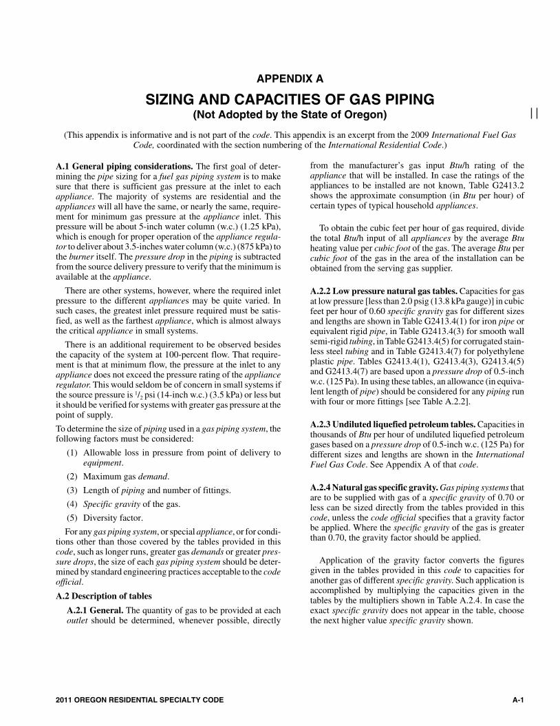
APPENDIX A
SIZING AND CAPACITIES OF GAS PIPING(Not Adopted by the State of Oregon)
(This appendix is informative and is not part of the code. This appendix is an excerpt from the 2009 International Fuel GasCode, coordinated with the section numbering of the International Residential Code.)
A.1 General piping considerations. The first goal of deter-mining the pipe sizing for a fuel gas piping system is to makesure that there is sufficient gas pressure at the inlet to eachappliance. The majority of systems are residential and theappliances will all have the same, or nearly the same, require-ment for minimum gas pressure at the appliance inlet. Thispressure will be about 5-inch water column (w.c.) (1.25 kPa),which is enough for proper operation of the appliance regula-tor to deliver about 3.5-inches water column (w.c.) (875 kPa) tothe burner itself. The pressure drop in the piping is subtractedfrom the source delivery pressure to verify that the minimum isavailable at the appliance.
There are other systems, however, where the required inletpressure to the different appliances may be quite varied. Insuch cases, the greatest inlet pressure required must be satis-fied, as well as the farthest appliance, which is almost alwaysthe critical appliance in small systems.
There is an additional requirement to be observed besidesthe capacity of the system at 100-percent flow. That require-ment is that at minimum flow, the pressure at the inlet to anyappliance does not exceed the pressure rating of the applianceregulator. This would seldom be of concern in small systems ifthe source pressure is 1/2 psi (14-inch w.c.) (3.5 kPa) or less butit should be verified for systems with greater gas pressure at thepoint of supply.
To determine the size of piping used in a gas piping system, thefollowing factors must be considered:
(1) Allowable loss in pressure from point of delivery toequipment.
(2) Maximum gas demand.
(3) Length of piping and number of fittings.
(4) Specific gravity of the gas.
(5) Diversity factor.
For any gas piping system, or special appliance, or for condi-tions other than those covered by the tables provided in thiscode, such as longer runs, greater gas demands or greater pres-sure drops, the size of each gas piping system should be deter-mined by standard engineering practices acceptable to the codeofficial.
A.2 Description of tables
A.2.1 General. The quantity of gas to be provided at eachoutlet should be determined, whenever possible, directly
from the manufacturer’s gas input Btu/h rating of theappliance that will be installed. In case the ratings of theappliances to be installed are not known, Table G2413.2shows the approximate consumption (in Btu per hour) ofcertain types of typical household appliances.
To obtain the cubic feet per hour of gas required, dividethe total Btu/h input of all appliances by the average Btuheating value per cubic foot of the gas. The average Btu percubic foot of the gas in the area of the installation can beobtained from the serving gas supplier.
A.2.2 Low pressure natural gas tables. Capacities for gasat low pressure [less than 2.0 psig (13.8 kPa gauge)] in cubicfeet per hour of 0.60 specific gravity gas for different sizesand lengths are shown in Table G2413.4(1) for iron pipe orequivalent rigid pipe, in Table G2413.4(3) for smooth wallsemi-rigid tubing, in Table G2413.4(5) for corrugated stain-less steel tubing and in Table G2413.4(7) for polyethyleneplastic pipe. Tables G2413.4(1), G2413.4(3), G2413.4(5)and G2413.4(7) are based upon a pressure drop of 0.5-inchw.c. (125 Pa). In using these tables, an allowance (in equiva-lent length of pipe) should be considered for any piping runwith four or more fittings [see Table A.2.2].
A.2.3 Undiluted liquefied petroleum tables. Capacities inthousands of Btu per hour of undiluted liquefied petroleumgases based on a pressure drop of 0.5-inch w.c. (125 Pa) fordifferent sizes and lengths are shown in the InternationalFuel Gas Code. See Appendix A of that code.
A.2.4 Natural gas specific gravity. Gas piping systems thatare to be supplied with gas of a specific gravity of 0.70 orless can be sized directly from the tables provided in thiscode, unless the code official specifies that a gravity factorbe applied. Where the specific gravity of the gas is greaterthan 0.70, the gravity factor should be applied.
Application of the gravity factor converts the figuresgiven in the tables provided in this code to capacities foranother gas of different specific gravity. Such application isaccomplished by multiplying the capacities given in thetables by the multipliers shown in Table A.2.4. In case theexact specific gravity does not appear in the table, choosethe next higher value specific gravity shown.
2011 OREGON RESIDENTIAL SPECIALTY CODE A-1
1M:\data\CODES\STATE CODES\Oregon\2011\Residential\Final VP\AppA_Oregon_Res_2011.vpWednesday, April 20, 2011 1:20:39 PM
Color profile: Generic CMYK printer profileComposite Default screen

APPENDIX A
A-2 2011 OREGON RESIDENTIAL SPECIALTY CODE
TABLE A.2.2EQUIVALENT LENGTHS OF PIPE FITTINGS AND VALVES
SCREWED FITTINGS1 90° WELDING ELBOWS AND SMOOTH BENDS2
45°/Ell 90°/Ell 180° closereturn bends Tee R/d = 1 R/d = 11/3 R/d = 2 R/d = 4 R/d = 6 R/d = 8
k factor = 0.42 0.90 2.00 1.80 0.48 0.36 0.27 0.21 0.27 0.36
L/d ratio4 n = 14 30 67 60 16 12 9 7 9 12
Nominalpipe size,
inches
Insidediameter d,
inches,Schedule 406 L = Equivalent Length In Feet of Schedule 40 (Standard-Weight) Straight Pipe6
1/2 0.622 0.73 1.55 3.47 3.10 0.83 0.62 0.47 0.36 0.47 0.62
3/4 0.824 0.96 2.06 4.60 4.12 1.10 0.82 0.62 0.48 0.62 0.82
1 1.049 1.22 2.62 5.82 5.24 1.40 1.05 0.79 0.61 0.79 1.05
11/4 1.380 1.61 3.45 7.66 6.90 1.84 1.38 1.03 0.81 1.03 1.38
11/2 1.610 1.88 4.02 8.95 8.04 2.14 1.61 1.21 0.94 1.21 1.61
2 2.067 2.41 5.17 11.5 10.3 2.76 2.07 1.55 1.21 1.55 2.07
21/2 2.469 2.88 6.16 13.7 12.3 3.29 2.47 1.85 1.44 1.85 2.47
3 3.068 3.58 7.67 17.1 15.3 4.09 3.07 2.30 1.79 2.30 3.07
4 4.026 4.70 10.1 22.4 20.2 5.37 4.03 3.02 2.35 3.02 4.03
5 5.047 5.88 12.6 28.0 25.2 6.72 5.05 3.78 2.94 3.78 5.05
6 6.065 7.07 15.2 33.8 30.4 8.09 6.07 4.55 3.54 4.55 6.07
8 7.981 9.31 20.0 44.6 40.0 10.6 7.98 5.98 4.65 5.98 7.98
10 10.02 11.7 25.0 55.7 50.0 13.3 10.0 7.51 5.85 7.51 10.0
12 11.94 13.9 29.8 66.3 59.6 15.9 11.9 8.95 6.96 8.95 11.9
14 13.13 15.3 32.8 73.0 65.6 17.5 13.1 9.85 7.65 9.85 13.1
16 15.00 17.5 37.5 83.5 75.0 20.0 15.0 11.2 8.75 11.2 15.0
18 16.88 19.7 42.1 93.8 84.2 22.5 16.9 12.7 9.85 12.7 16.9
20 18.81 22.0 47.0 105.0 94.0 25.1 18.8 14.1 11.0 14.1 18.8
24 22.63 26.4 56.6 126.0 113.0 30.2 22.6 17.0 13.2 17.0 22.6
(continued)
2M:\data\CODES\STATE CODES\Oregon\2011\Residential\Final VP\AppA_Oregon_Res_2011.vpWednesday, April 20, 2011 1:20:39 PM
Color profile: Generic CMYK printer profileComposite Default screen

APPENDIX A
2011 OREGON RESIDENTIAL SPECIALTY CODE A-3
TABLE A.2.2—continuedEQUIVALENT LENGTHS OF PIPE FITTINGS AND VALVES
MITER ELBOWS3 (No. of miters) WELDING TEES VALVES (screwed, flanged, or welded)
1-45° 1-60° 1-90° 2-90°5 3-90°5 Forged Miter3 Gate Globe AngleSwingCheck
k factor = 0.45 0.90 1.80 0.60 0.45 1.35 1.80 0.21 10 5.0 2.5
L/d ratio4 n = 15 30 60 20 15 45 60 7 333 167 83
Nominalpipe size,
inches
Insidediameter d,
inches,Schedule 406 L = Equivalent Length In Feet of Schedule 40 (Standard-Weight) Straight Pipe6
1/2 0.622 0.78 1.55 3.10 1.04 0.78 2.33 3.10 0.36 17.3 8.65 4.32
3/4 0.824 1.03 2.06 4.12 1.37 1.03 3.09 4.12 0.48 22.9 11.4 5.72
1 1.049 1.31 2.62 5.24 1.75 1.31 3.93 5.24 0.61 29.1 14.6 7.27
11/4 1.380 1.72 3.45 6.90 2.30 1.72 5.17 6.90 0.81 38.3 19.1 9.58
11/2 1.610 2.01 4.02 8.04 2.68 2.01 6.04 8.04 0.94 44.7 22.4 11.2
2 2.067 2.58 5.17 10.3 3.45 2.58 7.75 10.3 1.21 57.4 28.7 14.4
21/2 2.469 3.08 6.16 12.3 4.11 3.08 9.25 12.3 1.44 68.5 34.3 17.1
3 3.068 3.84 7.67 15.3 5.11 3.84 11.5 15.3 1.79 85.2 42.6 21.3
4 4.026 5.04 10.1 20.2 6.71 5.04 15.1 20.2 2.35 112.0 56.0 28.0
5 5.047 6.30 12.6 25.2 8.40 6.30 18.9 25.2 2.94 140.0 70.0 35.0
6 6.065 7.58 15.2 30.4 10.1 7.58 22.8 30.4 3.54 168.0 84.1 42.1
8 7.981 9.97 20.0 40.0 13.3 9.97 29.9 40.0 4.65 222.0 111.0 55.5
10 10.02 12.5 25.0 50.0 16.7 12.5 37.6 50.0 5.85 278.0 139.0 69.5
12 11.94 14.9 29.8 59.6 19.9 14.9 44.8 59.6 6.96 332.0 166.0 83.0
14 13.13 16.4 32.8 65.6 21.9 16.4 49.2 65.6 7.65 364.0 182.0 91.0
16 15.00 18.8 37.5 75.0 25.0 18.8 56.2 75.0 8.75 417.0 208.0 104.0
18 16.88 21.1 42.1 84.2 28.1 21.1 63.2 84.2 9.85 469.0 234.0 117.0
20 18.81 23.5 47.0 94.0 31.4 23.5 70.6 94.0 11.0 522.0 261.0 131.0
24 22.63 28.3 56.6 113.0 37.8 28.3 85.0 113.0 13.2 629.0 314.0 157.0
For SI: 1 foot = 305 mm, 1 degree = 0.01745 rad.Note: Values for welded fittings are for conditions where bore is not obstructed by weld spatter or backing rings. If appreciably obstructed, use values for “Screwed
Fittings.”1. Flanged fittings have three-fourths the resistance of screwed elbows and tees.2. Tabular figures give the extra resistance due to curvature alone to which should be added the full length of travel.3. Small size socket-welding fittings are equivalent to miter elbows and miter tees.4. Equivalent resistance in number of diameters of straight pipe computed for a value of (f - 0.0075) from the relation (n - k/4f).5. For condition of minimum resistance where the centerline length of each miter is between d and 21/2d.6. For pipe having other inside diameters, the equivalent resistance may be computed from the above n values.Source: Crocker, S. Piping Handbook, 4th ed., Table XIV, pp. 100-101.Copyright 1945 by McGraw-Hill, Inc. Used by permission of McGraw-Hill Book Company.
3M:\data\CODES\STATE CODES\Oregon\2011\Residential\Final VP\AppA_Oregon_Res_2011.vpWednesday, April 20, 2011 1:20:40 PM
Color profile: Generic CMYK printer profileComposite Default screen

TABLE A.2.4MULTIPLIERS TO BE USED WITH TABLES G2413.4(1)
THROUGH G2413.4(8) WHERE THE SPECIFIC GRAVITYOF THE GAS IS OTHER THAN 0.60
SPECIFICGRAVITY MULTIPLIER
SPECIFICGRAVITY MULTIPLIER
0.35 1.31 1.00 0.78
0.40 1.23 1.10 0.74
0.45 1.16 1.20 0.71
0.50 1.10 1.30 0.68
0.55 1.04 1.40 0.66
0.60 1.00 1.50 0.63
0.65 0.96 1.60 0.61
0.70 0.93 1.70 0.59
0.75 0.90 1.80 0.58
0.80 0.87 1.90 0.56
0.85 0.84 2.00 0.55
0.90 0.82 2.10 0.54
A.2.5 Higher pressure natural gas tables. Capacities forgas at pressures of 2.0 psig (13.8 kPa) or greater in cubic feetper hour of 0.60 specific gravity gas for different sizes andlengths are shown in Table G2413.4(2) for iron pipe orequivalent rigid pipe, Table G2413.4(4) for semi-rigid tub-ing, Table G2413.4(6) for corrugated stainless steel tubingand Table G2413.4(8) for polyethylene plastic pipe.
A.3 Use of capacity tables
A.3.1 Longest length method. This sizing method is con-servative in its approach by applying the maximum operat-ing conditions in the system as the norm for the system andby setting the length of pipe used to size any given part of thepiping system to the maximum value.
To determine the size of each section of gas piping in a sys-tem within the range of the capacity tables, proceed as follows.(also see sample calculations included in this Appendix).
(1) Divide the piping system into appropriate segmentsconsistent with the presence of tees, branch linesand main runs. For each segment, determine the gasload (assuming all appliances operate simulta-neously) and its overall length. An allowance (inequivalent length of pipe) as determined from TableA.2.2 shall be considered for piping segments thatinclude four or more fittings.
(2) Determine the gas demand of each appliance to beattached to the piping system. Where TablesG2413.4(1) through G2413.4(8) are to be used toselect the piping size, calculate the gas demand interms of cubic feet per hour for each piping systemoutlet.
(3) Where the piping system is for use with other thanundiluted liquefied petroleum gases, determine thedesign system pressure, the allowable loss in pres-sure (pressure drop), and specific gravity of the gasto be used in the piping system.
(4) Determine the length of piping from the point ofdelivery to the most remote outlet in the build-ing/piping system.
(5) In the appropriate capacity table, select the row show-ing the measured length or the next longer length if thetable does not give the exact length. This is the onlylength used in determining the size of any section ofgas piping. If the gravity factor is to be applied, thevalues in the selected row of the table are multiplied bythe appropriate multiplier from Table A.2.4.
(6) Use this horizontal row to locate ALL gas demandfigures for this particular system of piping.
(7) Starting at the most remote outlet, find the gasdemand for that outlet in the horizontal row justselected. If the exact figure of demand is not shown,choose the next larger figure left in the row.
(8) Opposite this demand figure, in the first row at thetop, the correct size of gas piping will be found.
(9) Proceed in a similar manner for each outlet and eachsection of gas piping. For each section of piping, deter-mine the total gas demand supplied by that section.
When a large number of piping components (such aselbows, tees and valves) are installed in a pipe run, additionalpressure loss can be accounted for by the use of equivalentlengths. Pressure loss across any piping component can beequated to the pressure drop through a length of pipe. Theequivalent length of a combination of only four elbows/teescan result in a jump to the next larger length row, resulting in asignificant reduction in capacity. The equivalent lengths in feetshown in Table A.2.2 have been computed on a basis that theinside diameter corresponds to that of Schedule 40 (stan-dard-weight) steel pipe, which is close enough for most pur-poses involving other schedules of pipe. Where a more specificsolution for equivalent length is desired, this may be made bymultiplying the actual inside diameter of the pipe in inches byn/12, or the actual inside diameter in feet by n (n can be readfrom the table heading). The equivalent length values can beused with reasonable accuracy for copper or brass fittings andbends although the resistance per foot of copper or brass pipe isless than that of steel. For copper or brass valves, however, theequivalent length of pipe should be taken as 45 percent longerthan the values in the table, which are for steel pipe.
A.3.2 Branch length method. This sizing method reducesthe amount of conservatism built into the traditional Lon-gest Length Method. The longest length as measured fromthe meter to the furthest remote appliance is only used tosize the initial parts of the overall piping system. The BranchLength Method is applied in the following manner:
(1) Determine the gas load for each of the connectedappliances.
(2) Starting from the meter, divide the piping systeminto a number of connected segments, and deter-mine the length and amount of gas that each segmentwould carry assuming that all appliances were oper-ated simultaneously. An allowance (in equivalentlength of pipe) as determined from Table A.2.2
APPENDIX A
A-4 2011 OREGON RESIDENTIAL SPECIALTY CODE
4M:\data\CODES\STATE CODES\Oregon\2011\Residential\Final VP\AppA_Oregon_Res_2011.vpWednesday, April 20, 2011 1:20:40 PM
Color profile: Generic CMYK printer profileComposite Default screen

should be considered for piping segments thatinclude four or more fittings.
(3) Determine the distance from the outlet of the gasmeter to the appliance furthest removed from themeter.
(4) Using the longest distance (found in Step 3), sizeeach piping segment from the meter to the mostremote appliance outlet.
(5) For each of these piping segments, use the longestlength and the calculated gas load for all of the con-nected appliances for the segment and begin the siz-ing process in Steps 6 through 8.
(6) Referring to the appropriate sizing table (based onoperating conditions and piping material), find thelongest length distance in the first column or the nextlarger distance if the exact distance is not listed. Theuse of alternative operating pressures and/or pres-sure drops will require the use of a different sizingtable, but will not alter the sizing methodology. Inmany cases, the use of alternative operating pressuresand/or pressure drops will require the approval ofboth the code official and the local gas serving utility.
(7) Trace across this row until the gas load is found or theclosest larger capacity if the exact capacity is not listed.
(8) Read up the table column and select the appropriatepipe size in the top row. Repeat Steps 6, 7 and 8 foreach pipe segment in the longest run.
(9) Size each remaining section of branch piping notpreviously sized by measuring the distance from thegas meter location to the most remote outlet in thatbranch, using the gas load of attached appliancesand following the procedures of Steps 2 through 8.
A.3.3 Hybrid pressure method. The sizing of a 2 psi (13.8kPa) gas piping system is performed using the traditionalLongest Length Method but with modifications. The 2 psi(13.8 kPa) system consists of two independent pressurezones, and each zone is sized separately. The Hybrid Pres-sure Method is applied as follows.
The sizing of the 2 psi (13.8 kPa) section (from the meterto the line regulator) is as follows:
(1) Calculate the gas load (by adding up the name plateratings) from all connected appliances. (In certaincircumstances the installed gas load may be increasedup to 50 percent to accommodate future addition ofappliances.) Ensure that the line regulator capacity isadequate for the calculated gas load and that therequired pressure drop (across the regulator) for thatcapacity does not exceed 3/4 psi (5.2 kPa) for a 2 psi(13.8 kPa) system. If the pressure drop across theregulator is too high (for the connected gas load),select a larger regulator.
(2) Measure the distance from the meter to the line reg-ulator located inside the building.
(3) If there are multiple line regulators, measure thedistance from the meter to the regulator furthestremoved from the meter.
(4) The maximum allowable pressure drop for the 2 psi(13.8 kPa) section is 1 psi (6.9 kPa).
(5) Referring to the appropriate sizing table (based onpiping material) for 2 psi (13.8 kPa) systems with a 1psi (6.9 kPa) pressure drop, find this distance in thefirst column, or the closest larger distance if theexact distance is not listed.
(6) Trace across this row until the gas load is found or theclosest larger capacity if the exact capacity is not listed.
(7) Read up the table column to the top row and selectthe appropriate pipe size.
(8) If there are multiple regulators in this portion of thepiping system, each line segment must be sized forits actual gas load, but using the longest length pre-viously determined above.
The low pressure section (all piping downstream of theline regulator) is sized as follows:
(1) Determine the gas load for each of the connectedappliances.
(2) Starting from the line regulator, divide the pipingsystem into a number of connected segments and/orindependent parallel piping segments, and determinethe amount of gas that each segment would carryassuming that all appliances were operated simulta-neously. An allowance (in equivalent length of pipe)as determined from Table A.2.2 should be consideredfor piping segments that include four or more fittings.
(3) For each piping segment, use the actual length orlongest length (if there are sub-branchlines) and thecalculated gas load for that segment and begin thesizing process as follows:
(a) Referring to the appropriate sizing table(based on operating pressure and piping mate-rial), find the longest length distance in thefirst column or the closest larger distance ifthe exact distance is not listed. The use of al-ternative operating pressures and/or pressuredrops will require the use of a different sizingtable, but will not alter the sizing methodol-ogy. In many cases, the use of alternative op-erating pressures and/or pressure drops mayrequire the approval of the code official.
(b) Trace across this row until the appliance gasload is found or the closest larger capacity ifthe exact capacity is not listed.
(c) Read up the table column to the top row andselect the appropriate pipe size.
(d) Repeat this process for each segment of thepiping system.
A.3.4 Pressure drop per 100 feet method. This sizingmethod is less conservative than the others, but it allows thedesigner to immediately see where the largest pressure dropoccurs in the system. With this information, modificationscan be made to bring the total drop to the critical appliancewithin the limitations that are presented to the designer.
APPENDIX A
2011 OREGON RESIDENTIAL SPECIALTY CODE A-5
5M:\data\CODES\STATE CODES\Oregon\2011\Residential\Final VP\AppA_Oregon_Res_2011.vpWednesday, April 20, 2011 1:20:40 PM
Color profile: Generic CMYK printer profileComposite Default screen

Follow the procedures described in the Longest LengthMethod for Steps (1) through (4) and (9).
For each piping segment, calculate the pressure dropbased on pipe size, length as a percentage of 100 feet (30480 mm), and gas flow. Table A.3.4 shows pressure drop per100 feet (30 480 mm) for pipe sizes from 1/2 inch (12.7 mm)through 2 inch (51 mm). The sum of pressure drops to thecritical appliance is subtracted from the supply pressure toverify that sufficient pressure will be available. If not, thelayout can be examined to find the high drop section(s) andsizing selections modified.
Note: Other values can be obtained by using the followingequation:
Desired ValueDesired Drop
Table Drop= ×MBH
For example, if it is desired to get flow through 3/4-inch (19.1mm) pipe at 2 inches/100 feet, multiple the capacity of3/4-inch pipe at 1 inch/100 feet by the square root of the pres-sure ratio:
1472
1147 1 414 208MBH
w c
w cMBH× = × =
" . .
" . ..
(MBH = 1000 Btu/h)
A.4 Use of sizing equations. Capacities of smooth wall pipe ortubing can also be determined by using the following formulae:
(1) High Pressure [1.5 psi (10.3 kPa) and above]:
( )Q
D P P Y
C fba Lr
=⋅ − ⋅
⋅ ⋅1816
512
22
.
( )=
− ⋅
⋅
⎡
⎣⎢⎢
⎤
⎦⎥⎥
2237 2 623 12
22
0 541
DP P Y
C Lr
.
.
(2) Low Pressure [Less than 1.5 psi (10.3 kPa)]:
QD
=⋅
⋅ ⋅1873
5
.ΔH
C fba Lr
=⋅
⎛⎝⎜
⎞⎠⎟
2313 2 623
0 541
DH
C Lr
.
.Δ
where:
Q = Rate, cubic feet per hour at 60°F and 30-inch mercurycolumn
D = Inside diameter of pipe, in.
P1 = Upstream pressure, psia
P2 = Downstream pressure, psia
Y = Superexpansibility factor = 1/supercompressibility fac-tor
Cr = Factor for viscosity, density and temperature*
= ⎛⎝⎜
⎞⎠⎟0 00354
0 152
..
STZS
Note: See Table 402.4 for Y and Cr for natural gas andpropane.
S = Specific gravity of gas at 60°F and 30-inch mercurycolumn (0.60 for natural gas, 1.50 for propane), or =1488μ
T = Absolute temperature, °F or = t + 460
t = Temperature, °F
Z = Viscosity of gas, centipoise (0.012 for natural gas,0.008 for propane), or = 1488µ
fba = Base friction factor for air at 60°F (CF=1)
L = Length of pipe, ft
ΔH = Pressure drop, in. w.c. (27.7 in. H2O = 1 psi)
(For SI, see Section G2413.4)
A.5 Pipe and tube diameters. Where the internal diameter isdetermined by the formulas in Section G2413.4, Tables A.5.1and A.5.2 can be used to select the nominal or standard pipesize based on the calculated internal diameter.
APPENDIX A
A-6 2011 OREGON RESIDENTIAL SPECIALTY CODE
TABLE A.3.4THOUSANDS OF Btu/h (MBH) OF NATURAL GAS PER 100 FEET OF PIPE AT
VARIOUS PRESSURE DROPS AND PIPE DIAMETERS
PRESSURE DROP PER100 FEET IN INCHES
W.C.
PIPE SIZES (inch)
1/23/4 1 11/4 11/2 2
0.2 31 64 121 248 372 716
0.3 38 79 148 304 455 877
0.5 50 104 195 400 600 1160
1.0 71 147 276 566 848 1640
For SI: 1 inch = 25.4 mm, 1 foot = 304.8 mm.
6M:\data\CODES\STATE CODES\Oregon\2011\Residential\Final VP\AppA_Oregon_Res_2011.vpWednesday, April 20, 2011 1:20:40 PM
Color profile: Generic CMYK printer profileComposite Default screen

TABLE A.5.1SCHEDULE 40 STEEL PIPE STANDARD SIZES
NOMINALSIZE(in.)
INTERNALDIAMETER
(in.)
NOMINALSIZE(in.)
INTERNALDIAMETER
(in.)
1/4 0.364 11/2 1.610
3/8 0.493 2 2.067
1/2 0.622 21/2 2.469
3/4 0.824 3 3.068
1 1.049 31/2 3.548
11/4 1.380 4 4.026
A.6 Use of sizing charts. A third method of sizing gas piping isdetailed below as an option that is useful when large quantities ofpiping are involved in a job (e.g., an apartment house) and materialcosts are of concern. If the user is not completely familiar with thismethod, the resulting pipe sizing should be checked by a knowl-edgeable gas engineer. The sizing charts are applied as follows.
(1) With the layout developed according to Section R106.1.1of the code, indicate in each section the design gas flowunder maximum operation conditions. For many layouts,the maximum design flow will be the sum of all connectedloads. However, in some cases, certain combinations ofappliances will not occur simultaneously (e.g., gas heatingand air conditioning). For these cases, the design flow is thegreatest gas flow that can occur at any one time.
(2) Determine the inlet gas pressure for the system beingdesigned. In most cases, the point of inlet will be the gasmeter or service regulator, but in the case of a systemaddition, it could be the point of connection to the exist-ing system.
(3) Determine the minimum pressure required at the inletto the critical appliance. Usually, the critical item willbe the appliance with the highest required pressure forsatisfactory operation. If several items have the samerequired pressure, it will be the one with the greatestlength of piping from the system inlet.
(4) The difference between the inlet pressure and criticalitem pressure is the allowable system pressure drop.Figures A.6(a) and A.6(b) show the relationshipbetween gas flow, pipe size and pipe length for naturalgas with 0.60 specific gravity.
(5) To use Figure A.6(a) (low pressure applications), calcu-late the piping length from the inlet to the critical utiliza-tion equipment. Increase this length by 50 percent to allowfor fittings. Divide the allowable pressure drop by theequivalent length (in hundreds of feet) to determine theallowable pressure drop per hundred feet. Select the pipesize from Figure A.6(a) for the required volume of flow.
(6) To use Figure A.6(b) (high pressure applications), cal-culate the equivalent length as above. Calculate theindex number for Figure A.6(b) by dividing the differ-ence between the squares of the absolute values of inletand outlet pressures by the equivalent length (in hun-dreds of feet). Select the pipe size from Figure A.6(b)for the gas volume required.
APPENDIX A
2011 OREGON RESIDENTIAL SPECIALTY CODE A-7
TABLE A.5.2COPPER TUBE STANDARD SIZES
TUBE TYPE
NOMINAL ORSTANDARD SIZE
(inches)
INTERNALDIAMETER
(inches)
K 1/4 0.305
L 1/4 0.315
ACR (D) 3/8 0.315
ACR (A) 3/8 0.311
K 3/8 0.402
L 3/8 0.430
ACR (D) 1/2 0.430
ACR (A) 1/2 0.436
K 1/2 0.527
L 1/2 0.545
ACR (D) 5/8 0.545
ACR (A) 5/8 0.555
K 5/8 0.652
L 5/8 0.666
ACR (D) 3/4 0.666
ACR (A) 3/4 0.680
K 3/4 0.745
L 3/4 0.785
ACR 7/8 0.785
K 1 0.995
L 1 1.025
ACR 11/8 1.025
K 11/4 1.245
L 11/4 1.265
ACR 13/8 1.265
K 11/2 1.481
L 11/2 1.505
ACR 15/8 1.505
K 2 1.959
L 2 1.985
ACR 21/8 1.985
K 21/2 2.435
L 21/2 2.465
ACR 25/8 2.465
K 3 2.907
L 3 2.945
ACR 31/8 2.945
7M:\data\CODES\STATE CODES\Oregon\2011\Residential\Final VP\AppA_Oregon_Res_2011.vpWednesday, April 20, 2011 1:20:41 PM
Color profile: Generic CMYK printer profileComposite Default screen

APPENDIX A
A-8 2011 OREGON RESIDENTIAL SPECIALTY CODE
FIGURE A.6(a)CAPACITY OF NATURAL GAS PIPING, LOW PRESSURE (0.60 WC)
FIGURE A.6 (b)CAPACITY OF NATURAL GAS PIPING, HIGH PRESSURE (1.5 psi and above)
8M:\data\CODES\STATE CODES\Oregon\2011\Residential\Final VP\AppA_Oregon_Res_2011.vpWednesday, April 20, 2011 1:20:50 PM
Color profile: Generic CMYK printer profileComposite Default screen

A.7 Examples of piping system design and sizing
A.7.1 Example 1: Longest length method. Determine therequired pipe size of each section and outlet of the pipingsystem shown in Figure A.7.1, with a designated pressuredrop of 0.5-inch w.c. (125 Pa) using the Longest LengthMethod. The gas to be used has 0.60 specific gravity and aheating value of 1,000 Btu/ft3 (37.5 MJ/m3).
Solution:
(1) Maximum gas demand for Outlet A:
Consumption (rating plate input, or Table G if neces2413 2. sary)
Btu of gas=
35,000 Btu per hour rating
1,000 Btu per cubic foot3 cubic= 5 feet per hour = 35 cfh
Maximum gas demand for Outlet B:
Consumption
Btu of gas
75,000
1,0007 cfh= = 5
Maximum gas demand for Outlet C:
Consumption
Btu of gas
35,000
1,00035 cfh= =
Maximum gas demand for Outlet D:
Consumption
Btu of gas
100,000
1,000100 cfh= =
(2) The length of pipe from the point of delivery to themost remote outlet (A) is 60 feet (18 288 mm). Thisis the only distance used.
(3) Using the row marked 60 feet (18 288 mm) in TableG2413.4(1):
(a) Outlet A, supplying 35 cfh (0.99 m3/hr), re-quires 3/8-inch pipe.
(b) Outlet B, supplying 75 cfh (2.12 m3/hr), re-quires 3/4-inch pipe.
(c) Section 1, supplying Outlets A and B, or 110cfh (3.11 m3/hr), requires 3/4-inch pipe.
(d) Section 2, supplying Outlets C and D, or 135cfh (3.82 m3/hr), requires 3/4-inch pipe.
(e) Section 3, supplying Outlets A, B, C and D, or245 cfh (6.94 m3/hr), requires 1-inch pipe.
(4) If a different gravity factor is applied to this exam-ple, the values in the row marked 60 feet (18 288mm) of Table G2413.4(1) would be multiplied bythe appropriate multiplier from Table A.2.4 and theresulting cubic feet per hour values would be used tosize the piping.
Section A.7.2 through A7.4 note: These examples are based ontables found in the International Fuel Gas Code.
A.7.2 Example 2: Hybrid or dual pressure systems.Determine the required CSST size of each section of thepiping system shown in Figure A.7.2, with a designatedpressure drop of 1 psi (6.9 kPa) for the 2 psi (13.8 kPa) sec-tion and 3-inch w.c. (0.75 kPa) pressure drop for the 13-inchw.c. (2.49 kPa) section. The gas to be used has 0.60 specificgravity and a heating value of 1,000 Btu/ft3 (37.5 MJ/ m3).
Solution
(1) Size 2 psi (13.8 kPa) line using Table 402.4(16).
(2) Size 10-inch w.c. (2.5 kPa) lines using Table402.4(14).
(3) Using the following, determine if sizing tables canbe used.
(a) Total gas load shown in Figure A.7.2 equals110 cfh (3.11 m3/hr).
(b) Determine pressure drop across regulator[see notes in Table 402.4 (16)].
APPENDIX A
2011 OREGON RESIDENTIAL SPECIALTY CODE A-9
OUTLET C40 GAL. AUTOMATICWATER HEATER35,000 BTU/H
OUTLET DFURNACE100,000 BTU/H
SECTION 220 FT
SECTION 110 FT 15 FT
5 FT
OUTLET ACLOTHES DRYER35,000 BTU/H
15 FT
OUTLET BRANGE/OVEN UNIT75,000 BTU/H
POINT OF DELIVERY
10 FT
SECTION 320 FT
FIGURE A.7.1PIPING PLAN SHOWING A STEEL PIPING SYSTEM
M
M
Length of runs:
A = 100 ft
B = 15 ft
C = 10 ft
D = 25 ft
Key:
Manifold
Shut-off valve
Pressure regulator
Gas meter
2 psiggas meter
110 cfh
Section A
Section B Furnace60 cfh
Waterheater30 cfh
2 psigzone
10 in.w.c.zone
SectionD
SectionC
Dryer20 cfh
FIGURE A.7.2PIPING PLAN SHOWING A CSST SYSTEM
9M:\data\CODES\STATE CODES\Oregon\2011\Residential\Final VP\AppA_Oregon_Res_2011.vpWednesday, April 20, 2011 1:21:23 PM
Color profile: Generic CMYK printer profileComposite Default screen

(c) If pressure drop across regulator exceeds 3/4
psig (5.2 kPa), Table 402.4 (16) cannot beused. Note: If pressure drop exceeds 3/4 psi (5.2kPa), then a larger regulator must be selectedor an alternative sizing method must be used.
(d) Pressure drop across the line regulator [for110 cfh (3.11 m3/hr)] is 4-inch w.c. (0.99 kPa)based on manufacturer’s performance data.
(e) Assume the CSST manufacturer has tubingsizes or EHDs of 13, 18, 23 and 30.
(4) Section A [2 psi (13.8 kPa) zone]
(a) Distance from meter to regulator = 100 feet(30 480 mm).
(b) Total load supplied by A = 110 cfh (3.11m3/hr) (furnace + water heater + dryer).
(c) Table 402.4 (16) shows that EHD size 18should be used.
Note: It is not unusual to oversize the supplyline by 25 to 50 percent of the as-installedload. EHD size 18 has a capacity of 189 cfh(5.35 m3/hr).
(5) Section B (low pressure zone)
(a) Distance from regulator to furnace is 15 feet(4572 mm).
(b) Load is 60 cfh (1.70 m3/hr).
(c) Table 402.4 (14) shows that EHD size 13should be used.
(6) Section C (low pressure zone)
(a) Distance from regulator to water heater is 10feet (3048 mm).
(b) Load is 30 cfh (0.85 m3/hr).
(c) Table 402.4 (14) shows that EHD size 13should be used.
(7) Section D (low pressure zone)
(a) Distance from regulator to dryer is 25 feet(7620 mm).
(b) Load is 20 cfh (0.57 m3/hr).
(c) Table 402.4(14) shows that EHD size 13should be used.
A.7.3 Example 3: Branch length method. Determine therequired semi-rigid copper tubing size of each section of thepiping system shown in Figure A.7.3, with a designatedpressure drop of 1-inch w.c. (250 Pa) (using the BranchLength Method). The gas to be used has 0.60 specific grav-ity and a heating value of 1,000 Btu/ft3 (37.5 MJ/m3).
Solution
(1) Section A
(a) The length of tubing from the point of deliv-ery to the most remote appliance is 50 feet (15240 mm), A + C.
(b) Use this longest length to size Sections A andC.
(c) Using the row marked 50 feet (15 240 mm) inTable 402.4(8), Section A, supplying 220 cfh(6.2 m3/hr) for four appliances requires1-inch tubing.
(2) Section B
(a) The length of tubing from the point of deliv-ery to the range/oven at the end of Section B is30 feet (9144 mm), A + B.
(b) Use this branch length to size Section B only.
(c) Using the row marked 30 feet (9144 mm) inTable 402.4(8), Section B, supplying 75 cfh(2.12 m3/hr) for the range/oven requires1/2-inch tubing.
(3) Section C
(a) The length of tubing from the point of deliv-ery to the dryer at the end of Section C is 50feet (15 240 mm), A + C.
(b) Use this branch length (which is also the lon-gest length) to size Section C.
(c) Using the row marked 50 feet (15 240 mm) inTable 402.4(8), Section C, supplying 30 cfh(0.85 m3/hr) for the dryer requires 3/8-inch tub-ing.
(4) Section D
(a) The length of tubing from the point of deliv-ery to the water heater at the end of Section Dis 30 feet (9144 mm), A + D.
(b) Use this branch length to size Section D only.
(c) Using the row marked 30 feet (9144 mm) inTable 402.4(8), Section D, supplying 35 cfh(0.99 m3/hr) for the water heater requires3/8-inch tubing.
APPENDIX A
A-10 2011 OREGON RESIDENTIAL SPECIALTY CODE
Range/oven75 cfh
Section C
Dryer30 cfh
M
M
Section A220 cfh Section D
Section E
Furnace80 cfh
Waterheater35 cfh
Length of runs:
A = 20 ft
B = 10 ft
C = 30 ft
D = 10 ft
E = 10 ft
Key:
Manifold
Shut-off valve
Gas meter
Total gas load = 220 cfh
Section B
FIGURE A.7.3PIPING PLAN SHOWING A COPPER TUBING SYSTEM
10M:\data\CODES\STATE CODES\Oregon\2011\Residential\Final VP\AppA_Oregon_Res_2011.vpWednesday, April 20, 2011 1:21:24 PM
Color profile: Generic CMYK printer profileComposite Default screen
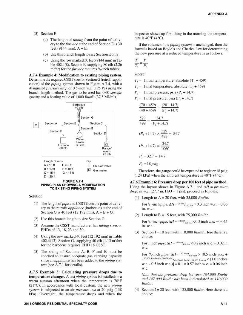
(5) Section E
(a) The length of tubing from the point of deliv-ery to the furnace at the end of Section E is 30feet (9144 mm), A + E.
(b) Use this branch length to size Section E only.
(c) Using the row marked 30 feet (9144 mm) in Ta-ble 402.4(8), Section E, supplying 80 cfh (2.26m3/hr) for the furnace requires 1/2-inch tubing.
A.7.4 Example 4: Modification to existing piping system.Determine the required CSST size for Section G (retrofit appli-cation) of the piping system shown in Figure A.7.4, with adesignated pressure drop of 0.5-inch w.c. (125 Pa) using thebranch length method. The gas to be used has 0.60 specificgravity and a heating value of 1,000 Btu/ft3 (37.5 MJ/m3).
Solution
(1) The length of pipe and CSST from the point of deliv-ery to the retrofit appliance (barbecue) at the end ofSection G is 40 feet (12 192 mm), A + B + G.
(2) Use this branch length to size Section G.
(3) Assume the CSST manufacturer has tubing sizes orEHDs of 13, 18, 23 and 30.
(4) Using the row marked 40 feet (12 192 mm) in Table402.4(13), Section G, supplying 40 cfh (1.13 m3/hr)for the barbecue requires EHD 18 CSST.
(5) The sizing of Sections A, B, F and E must bechecked to ensure adequate gas carrying capacitysince an appliance has been added to the piping sys-tem (see A.7.1 for details).
A.7.5 Example 5: Calculating pressure drops due totemperature changes. A test piping system is installed on awarm autumn afternoon when the temperature is 70°F(21°C). In accordance with local custom, the new pipingsystem is subjected to an air pressure test at 20 psig (138kPa). Overnight, the temperature drops and when the
inspector shows up first thing in the morning the tempera-ture is 40°F (4°C).
If the volume of the piping system is unchanged, then theformula based on Boyle’s and Charles’ law for determiningthe new pressure at a reduced temperature is as follows:
T
T
P
P1
2
1
2
=
where:
T1 = Initial temperature, absolute (T1 + 459)
T2 = Final temperature, absolute (T2 + 459)
P1 = Initial pressure, psia (P1 + 14.7)
P2 = Final pressure, psia (P2 + 14.7)
( )( )
( . )( . )
70 45940 459
20 14 714 72
++
= ++P
529499
34 714 72
=+
.( . )P
( . ) .P2 14 7529499
34 7+ × =
( . ).
.P2 14 7
34 71060
+ =
P2 32 7 14 7= −. .
P psig2 18=
Therefore, the gauge could be expected to register 18 psig(124 kPa) when the ambient temperature is 40�F (4�C).
A7.6 Example 6: Pressure drop per 100 feet of pipe method.Using the layout shown in Figure A.7.1 and ΔH = pressuredrop, in w.c. (27.7 in. H2O = 1 psi), proceed as follows:
(1) Length to A = 20 feet, with 35,000 Btu/hr.
For 1/2-inch pipe, ΔH = 20 feet/100 feet × 0.3 inch w.c. = 0.06in. w.c.
(2) Length to B = 15 feet, with 75,000 Btu/hr.
For 3/4-inch pipe, ΔH = 15 feet/100 feet× 0.3 inch w.c. = 0.045in. w.c.
(3) Section 1 = 10 feet, with 110,000 Btu/hr. Here there is achoice:
For 1 inch pipe: ΔH = 10 feet/100 feet× 0.2 inch w.c. = 0.02 inw.c.
For 3/4-inch pipe: ΔH = 10 feet/100 feet × [0.5 inch w.c. +(110,000 Btu/hr-104,000 Btu/hr)/(147,000 Btu/hr-104,000 Btu/hr) × (1.0 inchesw.c. - 0.5 inch w.c.)] = 0.1 × 0.57 inch w.c. = 0.06 inchw.c.
Note that the pressure drop between 104,000 Btu/hrand 147,000 Btu/hr has been interpolated as 110,000Btu/hr.
(4) Section 2 = 20 feet, with 135,000 Btu/hr. Here there is achoice:
APPENDIX A
2011 OREGON RESIDENTIAL SPECIALTY CODE A-11
M
M
Length of runs:
A = 15 ft E = 5 ft
B = 10 ft F = 10 ft
C = 15 ft G = 15 ft
D = 20 ft
Key:
Shut-off valve
Gas meter
Section A Section B
Section G
Section C
Section E
Section DSection F
Furnace80 cfh
Waterheater30 cfh
Range/overn75 cfh
Barbecue40 cfh
FIGURE A.7.4PIPING PLAN SHOWING A MODIFICATION
TO EXISTING PIPING SYSTEM
11M:\data\CODES\STATE CODES\Oregon\2011\Residential\Final VP\AppA_Oregon_Res_2011.vpWednesday, April 20, 2011 1:21:24 PM
Color profile: Generic CMYK printer profileComposite Default screen

For 1-inch pipe: ΔH = 20 feet/100 feet × [0.2 inch w.c. +(14,000 Btu/hr)/(27,000 Btu/hr) × 0.1 inch w.c.)] = 0.05 inch w.c.)]
For 3/4-inch pipe: ΔH = 20 feet/100 feet × 1.0 inch w.c. = 0.2inch w.c.)
Note that the pressure drop between 121,000 Btu/hrand 148,000 Btu/hr has been interpolated as 135,000Btu/hr, but interpolation for the ¾-inch pipe (trivial for104,000 Btu/hr to 147,000 Btu/hr) was not used.
(5) Section 3 = 30 feet, with 245,000 Btu/hr. Here there is achoice:
For 1-inch pipe: ΔH = 30 feet/100 feet × 1.0 inches w.c. = 0.3inch w.c.
For 11/4-inch pipe: ΔH = 30 feet/100 feet × 0.2 inch w.c. =0.06 inch w.c.
Note that interpolation for these options is ignoredsince the table values are close to the 245,000 Btu/hrcarried by that section.
(6) The total pressure drop is the sum of the sectionapproaching A, Sections 1 and 3, or either of the fol-lowing, depending on whether an absolute minimum isneeded or the larger drop can be accommodated.
Minimum pressure drop to farthest appliance:
ΔH = 0.06 inch w.c. + 0.02 inch w.c. + 0.06 inch w.c. =0.14 inch w.c.
Larger pressure drop to the farthest appliance:
H = 0.06 inch w.c. + 0.06 inch w.c. + 0.3 inch w.c. =0.42 inch w.c.
Notice that Section 2 and the run to B do not enter intothis calculation, provided that the appliances have sim-ilar input pressure requirements.
For SI units: 1 Btu/hr = 0.293 W, 1 cubic foot = 0.028m3, 1 foot = 0.305 m, 1 inch w.c. = 249 Pa.
APPENDIX A
A-12 2011 OREGON RESIDENTIAL SPECIALTY CODE
12M:\data\CODES\STATE CODES\Oregon\2011\Residential\Final VP\AppA_Oregon_Res_2011.vpWednesday, April 20, 2011 1:21:24 PM
Color profile: Generic CMYK printer profileComposite Default screen

APPENDIX B
SIZING OF VENTING SYSTEMS SERVING APPLIANCES EQUIPPEDWITH DRAFT HOODS, CATEGORY I APPLIANCES, ANDAPPLIANCES LISTED FOR USE WITH TYPE B VENTS
(Not Adopted by the State of Oregon)
(This appendix is informative and is not part of the code. This appendix is an excerpt from the2009 International Fuel Gas Code, coordinated with the section numbering of the International Residential Code.)
EXAMPLES USING SINGLEAPPLIANCE VENTING TABLES
Example 1: Single draft-hood-equipped appliance.
An installer has a 120,000 British thermal unit (Btu) per hourinput appliance with a 5-inch-diameter draft hood outlet thatneeds to be vented into a 10-foot-high Type B vent system.What size vent should be used assuming (a) a 5-foot lateral sin-gle-wall metal vent connector is used with two 90-degreeelbows, or (b) a 5-foot lateral single-wall metal vent connectoris used with three 90-degree elbows in the vent system?
Solution:
Table G2428.2(2) should be used to solve this problem, becausesingle-wall metal vent connectors are being used with a Type Bvent.
(a) Read down the first column in Table G2428.2(2) untilthe row associated with a 10-foot height and 5-foot lat-eral is found. Read across this row until a vent capacity
greater than 120,000 Btu per hour is located in theshaded columns labeled “NAT Max” for draft-hood-equipped appliances. In this case, a 5-inch-diametervent has a capacity of 122,000 Btu per hour and may beused for this application.
(b) If three 90-degree elbows are used in the vent system,then the maximum vent capacity listed in the tablesmust be reduced by 10 percent (see Section G2428.2.3for single appliance vents). This implies that the 5-inch-diameter vent has an adjusted capacity of only110,000 Btu per hour. In this case, the vent system mustbe increased to 6 inches in diameter (see calculationsbelow).
122,000 (0.90) = 110,000 for 5-inch ventFrom Table G2428.2(2), Select 6-inch vent186,000 (0.90) = 167,000; This is greater than therequired 120,000. Therefore, use a 6-inch vent andconnector where three elbows are used.
2011 OREGON RESIDENTIAL SPECIALTY CODE B-1
For SI: 1 foot = 304.8 mm, 1 British thermal unit per hour = 0.2931W.Table G2428.2(2) is used when sizing a single-wall metal vent connectorattached to a Type B double-wall gas vent.Note: The appliance may be either Category I draft hood equipped or fan-assisted type.
FIGURE B-2TYPE B DOUBLE-WALL VENT SYSTEM SERVING
A SINGLE APPLIANCE WITH A SINGLE-WALLMETAL VENT CONNECTOR
For SI: 1 foot = 304.8 mm, 1 British thermal unit per hour = 0.2931 W.Table G2428.2(1) is used when sizing Type B double-wall gas vent connecteddirectly to the appliance.
Note: The appliance may be either Category I draft hood equipped or fan-assisted type.
FIGURE B-1TYPE B DOUBLE-WALL VENT SYSTEM SERVING A SINGLE
APPLIANCE WITH A TYPE B DOUBLE-WALL VENT
1M:\data\CODES\STATE CODES\Oregon\2011\Residential\Final VP\AppB_Oregon_Res_2011.vpWednesday, April 20, 2011 1:19:50 PM
Color profile: Generic CMYK printer profileComposite Default screen

B-2 2011 OREGON RESIDENTIAL SPECIALTY CODE
APPENDIX B
Table 504.2(3) of the International Fuel Gas Code is used when sizing a Type Bdouble-wall gas vent connector attached to a tile-lined masonry chimney.
Note: “A” is the equivalent cross-sectional area of the tile liner.
Note: The appliance may be either Category I draft hood equipped or fan-assisted type.
FIGURE B-3VENT SYSTEM SERVING A SINGLE APPLIANCE
WITH A MASONRY CHIMNEY OF TYPE BDOUBLE-WALL VENT CONNECTOR
Table 504.2(4) of the International Fuel Gas Code is used when sizing a single-wall vent connector attached to a tile-lined masonry chimney.
Note: “A” is the equivalent cross-sectional area of the tile liner.
Note: The appliance may be either Category I draft hood equipped or fan-assisted type.
FIGURE B-4VENT SYSTEM SERVING A SINGLE APPLIANCE
USING A MASONRY CHIMNEY AND ASINGLE-WALL METAL VENT CONNECTOR
Asbestos cement Type B or single-wall metal vent serving a single draft-hood-equipped appliance [see Table 504.2(5) of the International Fuel Gas Code].
FIGURE B-5ASBESTOS CEMENT TYPE B OR SINGLE-WALL
METAL VENT SYSTEM SERVING A SINGLEDRAFT-HOOD-EQUIPPED APPLIANCE
Table G2428.3(1) is used when sizing Type B double-wall vent connectorsattached to a Type B double-wall common vent.
Note: Each appliance may be either Category I draft hood equipped or fan-assisted type.
FIGURE B-6VENT SYSTEM SERVING TWO OR MORE APPLIANCES
WITH TYPE B DOUBLE-WALL VENT AND TYPE BDOUBLE-WALL VENT CONNECTOR
2M:\data\CODES\STATE CODES\Oregon\2011\Residential\Final VP\AppB_Oregon_Res_2011.vpWednesday, April 20, 2011 1:19:53 PM
Color profile: Generic CMYK printer profileComposite Default screen

2011 OREGON RESIDENTIAL SPECIALTY CODE B-3
APPENDIX B
Table G2428.3(2) is used when sizing single-wall vent connectors attached to aType B double-wall common vent.
Note: Each appliance may be either Category I draft hood equipped or fan-assisted type.
FIGURE B-7VENT SYSTEM SERVING TWO OR MORE APPLIANCES
WITH TYPE B DOUBLE-WALL VENT ANDSINGLE-WALL METAL VENT CONNECTORS
Table G2428.3(3) is used when sizing Type B double-wall vent connectorsattached to a tile-lined masonry chimney.
Note: “A” is the equivalent cross-sectional area of the tile liner.
Note: Each appliance may be either Category I draft hood equipped or fan-assisted type.
FIGURE B-8MASONRY CHIMNEY SERVING TWO OR MORE APPLIANCES
WITH TYPE B DOUBLE-WALL VENT CONNECTOR
Table G2428.3(4) is used when sizing single-wall metal vent connectorsattached to a tile-lined masonry chimney.
Note: “A” is the equivalent cross-sectional area of the tile liner.
Note: Each appliance may be either Category I draft hood equipped or fan-assisted type.
FIGURE B-9MASONRY CHIMNEY SERVING TWO OR MORE APPLIANCES
WITH SINGLE-WALL METAL VENT CONNECTORS
Asbestos cement Type B or single-wall metal pipe vent serving two or moredraft-hood-equipped appliances [see Table 504.3(5) of the International FuelGas Code].
FIGURE B-10ASBESTOS CEMENT TYPE B OR SINGLE-WALLMETAL VENT SYSTEM SERVING TWO OR MORE
DRAFT-HOOD-EQUIPPED APPLIANCES
3M:\data\CODES\STATE CODES\Oregon\2011\Residential\Final VP\AppB_Oregon_Res_2011.vpWednesday, April 20, 2011 1:19:56 PM
Color profile: Generic CMYK printer profileComposite Default screen
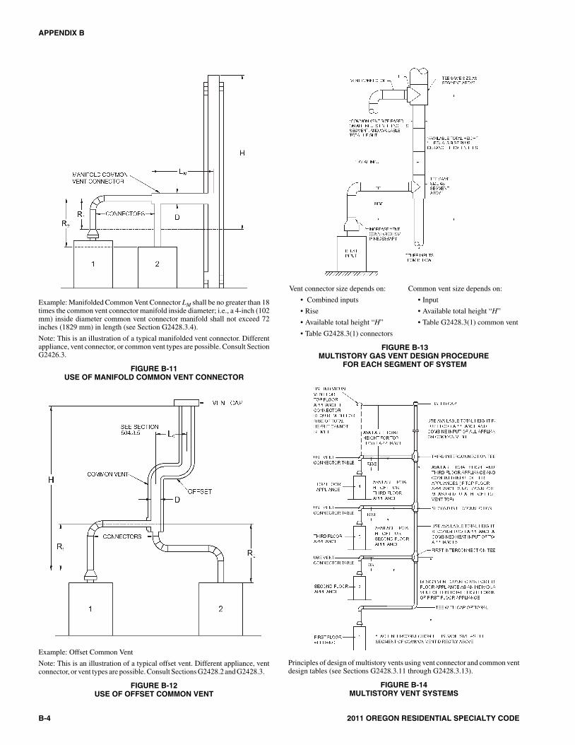
B-4 2011 OREGON RESIDENTIAL SPECIALTY CODE
APPENDIX B
Example: Manifolded Common Vent Connector LM shall be no greater than 18times the common vent connector manifold inside diameter; i.e., a 4-inch (102mm) inside diameter common vent connector manifold shall not exceed 72inches (1829 mm) in length (see Section G2428.3.4).
Note: This is an illustration of a typical manifolded vent connector. Differentappliance, vent connector, or common vent types are possible. Consult SectionG2426.3.
FIGURE B-11USE OF MANIFOLD COMMON VENT CONNECTOR
Example: Offset Common Vent
Note: This is an illustration of a typical offset vent. Different appliance, ventconnector, or vent types are possible. Consult Sections G2428.2 and G2428.3.
FIGURE B-12USE OF OFFSET COMMON VENT
Principles of design of multistory vents using vent connector and common ventdesign tables (see Sections G2428.3.11 through G2428.3.13).
FIGURE B-14MULTISTORY VENT SYSTEMS
Vent connector size depends on: Common vent size depends on:
• Input• Combined inputs
• Rise • Available total height “H”
• Available total height “H” • Table G2428.3(1) common vent
• Table G2428.3(1) connectors
FIGURE B-13MULTISTORY GAS VENT DESIGN PROCEDURE
FOR EACH SEGMENT OF SYSTEM
4M:\data\CODES\STATE CODES\Oregon\2011\Residential\Final VP\AppB_Oregon_Res_2011.vpWednesday, April 20, 2011 1:20:00 PM
Color profile: Generic CMYK printer profileComposite Default screen

Example 2: Single fan-assisted appliance.
An installer has an 80,000 Btu per hour input fan-assistedappliance that must be installed using 10 feet of lateral connec-tor attached to a 30-foot-high Type B vent. Two 90-degreeelbows are needed for the installation. Can a single-wall metalvent connector be used for this application?
Solution:
Table G2428.2(2) refers to the use of single-wall metal ventconnectors with Type B vent. In the first column find the rowassociated with a 30-foot height and a 10-foot lateral. Readacross this row, looking at the FAN Min and FAN Max col-umns, to find that a 3-inch-diameter single-wall metal vent con-nector is not recommended. Moving to the next larger sizesingle wall connector (4 inches), note that a 4-inch-diametersingle-wall metal connector has a recommended minimumvent capacity of 91,000 Btu per hour and a recommended maxi-mum vent capacity of 144,000 Btu per hour. The 80,000 Btu perhour fan-assisted appliance is outside this range, so the conclu-sion is that a single-wall metal vent connector cannot be used tovent this appliance using 10 feet of lateral for the connector.
However, if the 80,000 Btu per hour input appliance could bemoved to within 5 feet of the vertical vent, then a 4-inch single-wall metal connector could be used to vent the appliance. TableG2428.2(2) shows the acceptable range of vent capacities for a4-inch vent with 5 feet of lateral to be between 72,000 Btu perhour and 157,000 Btu per hour.
If the appliance cannot be moved closer to the vertical vent,then Type B vent could be used as the connector material. Inthis case, Table G2428.2(1) shows that for a 30-foot-high ventwith 10 feet of lateral, the acceptable range of vent capacitiesfor a 4-inch-diameter vent attached to a fan-assisted applianceis between 37,000 Btu per hour and 150,000 Btu per hour.
Example 3: Interpolating between table values.
An installer has an 80,000 Btu per hour input appliance with a4-inch-diameter draft hood outlet that needs to be vented into a12-foot-high Type B vent. The vent connector has a 5-foot lat-eral length and is also Type B. Can this appliance be ventedusing a 4-inch-diameter vent?
Solution:
Table G2428.2(1) is used in the case of an all Type B vent sys-tem. However, since there is no entry in Table G2428.2(1) for aheight of 12 feet, interpolation must be used. Read down the 4-inch diameter NAT Max column to the row associated with 10-foot height and 5-foot lateral to find the capacity value of77,000 Btu per hour. Read further down to the 15-foot height,5-foot lateral row to find the capacity value of 87,000 Btu perhour. The difference between the 15-foot height capacity valueand the 10-foot height capacity value is 10,000 Btu per hour.The capacity for a vent system with a 12-foot height is equal tothe capacity for a 10-foot height plus 2/5 of the differencebetween the 10-foot and 15-foot height values, or 77,000 + 2/5
(10,000) = 81,000 Btu per hour. Therefore, a 4-inch-diametervent may be used in the installation.
2011 OREGON RESIDENTIAL SPECIALTY CODE B-5
APPENDIX B
For SI: 1 foot = 304.8 mm, 1 British thermal unit per hour = 0.2931 W.
FIGURE B-15 (EXAMPLE 1)SINGLE DRAFT-HOOD-EQUIPPED APPLIANCE
For SI: 1 foot = 304.8 mm, 1 British thermal unit per hour = 0.2931 W.
FIGURE B-16 (EXAMPLE 2)SINGLE FAN-ASSISTED APPLIANCE
5M:\data\CODES\STATE CODES\Oregon\2011\Residential\Final VP\AppB_Oregon_Res_2011.vpWednesday, April 20, 2011 1:20:01 PM
Color profile: Generic CMYK printer profileComposite Default screen

EXAMPLES USING COMMON VENTING TABLES
Example 4: Common venting two draft-hood-equippedappliances.
A 35,000 Btu per hour water heater is to be common ventedwith a 150,000 Btu per hour furnace using a common vent witha total height of 30 feet. The connector rise is 2 feet for thewater heater with a horizontal length of 4 feet. The connectorrise for the furnace is 3 feet with a horizontal length of 8 feet.Assume single-wall metal connectors will be used with Type Bvent. What size connectors and combined vent should be usedin this installation?
Solution:
Table G2428.3(2) should be used to size single-wall metal ventconnectors attached to Type B vertical vents. In the vent con-nector capacity portion of Table G2428.3(2), find the row asso-ciated with a 30-foot vent height. For a 2-foot rise on the ventconnector for the water heater, read the shaded columns fordraft-hood-equipped appliances to find that a 3-inch-diametervent connector has a capacity of 37,000 Btu per hour. There-fore, a 3-inch single-wall metal vent connector may be usedwith the water heater. For a draft-hood-equipped furnace witha 3-foot rise, read across the appropriate row to find that a 5-inch-diameter vent connector has a maximum capacity of120,000 Btu per hour (which is too small for the furnace) and a6-inch-diameter vent connector has a maximum vent capacityof 172,000 Btu per hour. Therefore, a 6-inch-diameter ventconnector should be used with the 150,000 Btu per hour fur-nace. Since both vent connector horizontal lengths are less thanthe maximum lengths listed in Section G2428.3.2, the tablevalues may be used without adjustments.
In the common vent capacity portion of Table G2428.3(2),find the row associated with a 30-foot vent height and read overto the NAT + NAT portion of the 6-inch-diameter column tofind a maximum combined capacity of 257,000 Btu per hour.Since the two appliances total only 185,000 Btu per hour, a 6-inch common vent may be used.
Example 5a: Common venting a draft-hood-equippedwater heater with a fan-assisted furnace into a Type B vent.
In this case, a 35,000 Btu per hour input draft-hood-equippedwater heater with a 4-inch-diameter draft hood outlet, 2 feet ofconnector rise, and 4 feet of horizontal length is to be commonvented with a 100,000 Btu per hour fan-assisted furnace with a4-inch-diameter flue collar, 3 feet of connector rise, and 6 feetof horizontal length. The common vent consists of a 30-footheight of Type B vent. What are the recommended vent diame-ters for each connector and the common vent? The installerwould like to use a single-wall metal vent connector.
Solution:
Water Heater Vent Connector Diameter. Since the water heatervent connector horizontal length of 4 feet is less than the maxi-mum value listed in Section G2428.3.2, the venting table val-ues may be used without adjustments. Using the VentConnector Capacity portion of Table G2428.3(2), read downthe Total Vent Height (H) column to 30 feet and read across the2-foot Connector Rise (R) row to the first Btu per hour rating inthe NAT Max column that is equal to or greater than the waterheater input rating. The table shows that a 3-inch vent connec-tor has a maximum input rating of 37,000 Btu per hour.Although this is greater than the water heater input rating, a 3-inch vent connector is prohibited by Section G2428.3.17. A 4-
B-6 2011 OREGON RESIDENTIAL SPECIALTY CODE
APPENDIX B
FIGURE B-17 (EXAMPLE 4)COMMON VENTING TWO DRAFT-HOOD-EQUIPPED APPLIANCES
FIGURE B-18 (EXAMPLE 5A)COMMON VENTING A DRAFT HOOD WITH A FAN-ASSISTEDFURNACE INTO A TYPE B DOUBLE-WALL COMMON VENT
6M:\data\CODES\STATE CODES\Oregon\2011\Residential\Final VP\AppB_Oregon_Res_2011.vpWednesday, April 20, 2011 1:20:04 PM
Color profile: Generic CMYK printer profileComposite Default screen

inch vent connector has a maximum input rating of 67,000 Btuper hour and is equal to the draft hood outlet diameter. A 4-inchvent connector is selected. Since the water heater is equippedwith a draft hood, there are no minimum input rating restric-tions.
Furnace Vent Connector Diameter. Using the Vent Connec-tor Capacity portion of Table G2428.3(2), read down the TotalVent Height (H) column to 30 feet and across the 3-foot Con-nector Rise (R) row. Since the furnace has a fan-assisted com-bustion system, find the first FAN Max column with a Btu perhour rating greater than the furnace input rating. The 4-inchvent connector has a maximum input rating of 119,000 Btu perhour and a minimum input rating of 85,000 Btu per hour. The100,000 Btu per hour furnace in this example falls within thisrange, so a 4-inch connector is adequate. Since the furnace ventconnector horizontal length of 6 feet does not exceed the maxi-mum value listed in Section G2428.3.2, the venting table val-ues may be used without adjustment. If the furnace had aninput rating of 80,000 Btu per hour, then a Type B vent connec-tor [see Table G2428.3(1)] would be needed in order to meetthe minimum capacity limit.
Common Vent Diameter. The total input to the common ventis 135,000 Btu per hour. Using the Common Vent Capacity por-tion of Table G2428.3(2), read down the Total Vent Height (H)column to 30 feet and across this row to find the smallest ventdiameter in the FAN + NAT column that has a Btu per hour rat-ing equal to or greater than 135,000 Btu per hour. The 4-inchcommon vent has a capacity of 132,000 Btu per hour and the 5-inch common vent has a capacity of 202,000 Btu per hour.Therefore, the 5-inch common vent should be used in thisexample.
Summary. In this example, the installer may use a 4-inch-diameter, single-wall metal vent connector for the water heaterand a 4-inch-diameter, single-wall metal vent connector for thefurnace. The common vent should be a 5-inch-diameter Type Bvent.
Example 5b: Common venting into a masonry chimney.
In this case, the water heater and fan-assisted furnace of Exam-ple 5a are to be common vented into a clay tile-lined masonrychimney with a 30-foot height. The chimney is not exposed tothe outdoors below the roof line. The internal dimensions of theclay tile liner are nominally 8 inches by 12 inches. Assumingthe same vent connector heights, laterals, and materials foundin Example 5a, what are the recommended vent connectordiameters, and is this an acceptable installation?
Solution:
Table G2428.3(4) is used to size common venting installationsinvolving single-wall connectors into masonry chimneys.
Water Heater Vent Connector Diameter. Using TableG2428.3(4), Vent Connector Capacity, read down the TotalVent Height (H) column to 30 feet, and read across the 2-footConnector Rise (R) row to the first Btu per hour rating in theNAT Max column that is equal to or greater than the waterheater input rating. The table shows that a 3-inch vent connec-tor has a maximum input of only 31,000 Btu per hour while a 4-inch vent connector has a maximum input of 57,000 Btu perhour. A 4-inch vent connector must therefore be used.
Furnace Vent Connector Diameter. Using the Vent Connec-tor Capacity portion of Table G2428.3(4), read down the TotalVent Height (H) column to 30 feet and across the 3-foot Con-nector Rise (R) row. Since the furnace has a fan-assisted com-bustion system, find the first FAN Max column with a Btu perhour rating greater than the furnace input rating. The 4-inchvent connector has a maximum input rating of 127,000 Btu perhour and a minimum input rating of 95,000 Btu per hour. The100,000 Btu per hour furnace in this example falls within thisrange, so a 4-inch connector is adequate.
Masonry Chimney. From Table B-1, the equivalent area for anominal liner size of 8 inches by 12 inches is 63.6 squareinches. Using Table G2428.3(4), Common Vent Capacity, readdown the FAN + NAT column under the Minimum InternalArea of Chimney value of 63 to the row for 30-foot height tofind a capacity value of 739,000 Btu per hour. The combinedinput rating of the furnace and water heater, 135,000 Btu perhour, is less than the table value, so this is an acceptable instal-lation.
Section G2428.3.13 requires the common vent area to be nogreater than seven times the smallest listed appliance catego-rized vent area, flue collar area, or draft hood outlet area. Bothappliances in this installation have 4-inch-diameter outlets.From Table B-1, the equivalent area for an inside diameter of 4inches is 12.2 square inches. Seven times 12.2 equals 85.4,which is greater than 63.6, so this configuration is acceptable.
Example 5c: Common venting into an exterior masonrychimney.
In this case, the water heater and fan-assisted furnace of Exam-ples 5a and 5b are to be common vented into an exteriormasonry chimney. The chimney height, clay tile liner dimen-sions, and vent connector heights and laterals are the same as inExample 5b. This system is being installed in Charlotte, NorthCarolina. Does this exterior masonry chimney need to berelined? If so, what corrugated metallic liner size is recom-mended? What vent connector diameters are recommended?
Solution:
According to Section 504.3.20 of the International Fuel GasCode, Type B vent connectors are required to be used with exte-rior masonry chimneys. Use Table 504.3(7) of the Interna-tional Fuel Gas Code to size FAN+NAT common ventinginstallations involving Type-B double wall connectors intoexterior masonry chimneys.
The local 99-percent winter design temperature needed touse Table 504.3(7) can be found in the ASHRAE Handbook ofFundamentals. For Charlotte, North Carolina, this design tem-perature is 19°F.
Chimney Liner Requirement. As in Example 5b, use the 63square inch Internal Area columns for this size clay tile liner.Read down the 63 square inch column of Table 504.3(7a) of theInternational Fuel Gas Code to the 30-foot height row to findthat the combined appliance maximum input is 747,000 Btu perhour. The combined input rating of the appliances in this instal-lation, 135,000 Btu per hour, is less than the maximum value,so this criterion is satisfied. Table 504.3(7b), at a 19°F designtemperature, and at the same vent height and internal area usedabove, shows that the minimum allowable input rating of a
2011 OREGON RESIDENTIAL SPECIALTY CODE B-7
APPENDIX B
7M:\data\CODES\STATE CODES\Oregon\2011\Residential\Final VP\AppB_Oregon_Res_2011.vpWednesday, April 20, 2011 1:20:04 PM
Color profile: Generic CMYK printer profileComposite Default screen
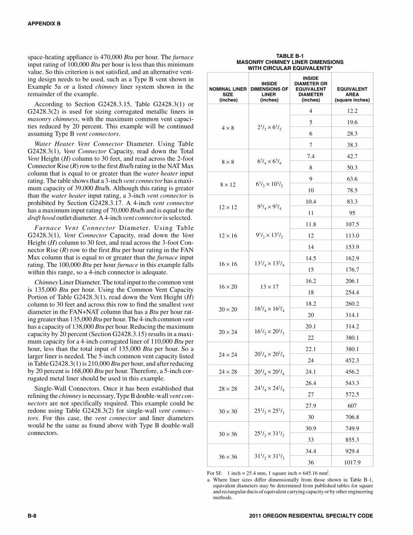
space-heating appliance is 470,000 Btu per hour. The furnaceinput rating of 100,000 Btu per hour is less than this minimumvalue. So this criterion is not satisfied, and an alternative vent-ing design needs to be used, such as a Type B vent shown inExample 5a or a listed chimney liner system shown in theremainder of the example.
According to Section G2428.3.15, Table G2428.3(1) orG2428.3(2) is used for sizing corrugated metallic liners inmasonry chimneys, with the maximum common vent capaci-ties reduced by 20 percent. This example will be continuedassuming Type B vent connectors.
Water Heater Vent Connector Diameter. Using TableG2428.3(1), Vent Connector Capacity, read down the TotalVent Height (H) column to 30 feet, and read across the 2-footConnector Rise (R) row to the first Btu/h rating in the NAT Maxcolumn that is equal to or greater than the water heater inputrating. The table shows that a 3-inch vent connector has a maxi-mum capacity of 39,000 Btu/h. Although this rating is greaterthan the water heater input rating, a 3-inch vent connector isprohibited by Section G2428.3.17. A 4-inch vent connectorhas a maximum input rating of 70,000 Btu/h and is equal to thedraft hood outlet diameter. A 4-inch vent connector is selected.
Furnace Vent Connector Diameter. Using TableG2428.3(1), Vent Connector Capacity, read down the VentHeight (H) column to 30 feet, and read across the 3-foot Con-nector Rise (R) row to the first Btu per hour rating in the FANMax column that is equal to or greater than the furnace inputrating. The 100,000 Btu per hour furnace in this example fallswithin this range, so a 4-inch connector is adequate.
Chimney Liner Diameter. The total input to the common ventis 135,000 Btu per hour. Using the Common Vent CapacityPortion of Table G2428.3(1), read down the Vent Height (H)column to 30 feet and across this row to find the smallest ventdiameter in the FAN+NAT column that has a Btu per hour rat-ing greater than 135,000 Btu per hour. The 4-inch common venthas a capacity of 138,000 Btu per hour. Reducing the maximumcapacity by 20 percent (Section G2428.3.15) results in a maxi-mum capacity for a 4-inch corrugated liner of 110,000 Btu perhour, less than the total input of 135,000 Btu per hour. So alarger liner is needed. The 5-inch common vent capacity listedin Table G2428.3(1) is 210,000 Btu per hour, and after reducingby 20 percent is 168,000 Btu per hour. Therefore, a 5-inch cor-rugated metal liner should be used in this example.
Single-Wall Connectors. Once it has been established thatrelining the chimney is necessary, Type B double-wall vent con-nectors are not specifically required. This example could beredone using Table G2428.3(2) for single-wall vent connec-tors. For this case, the vent connector and liner diameterswould be the same as found above with Type B double-wallconnectors.
B-8 2011 OREGON RESIDENTIAL SPECIALTY CODE
APPENDIX B
TABLE B-1MASONRY CHIMNEY LINER DIMENSIONS
WITH CIRCULAR EQUIVALENTSa
NOMINAL LINERSIZE
(inches)
INSIDEDIMENSIONS OF
LINER(inches)
INSIDEDIAMETER OREQUIVALENT
DIAMETER(inches)
EQUIVALENTAREA
(square inches)
4 × 8 21/2 × 61/2
4 12.2
5 19.6
6 28.3
7 38.3
8 × 8 63/4 × 63/4
7.4 42.7
8 50.3
8 × 12 61/2 × 101/2
9 63.6
10 78.5
12 × 12 93/4 × 93/4
10.4 83.3
11 95
12 × 16 91/2 × 131/2
11.8 107.5
12 113.0
14 153.9
16 × 16 131/4 × 131/4
14.5 162.9
15 176.7
16 × 20 13 × 1716.2 206.1
18 254.4
20 × 20 163/4 × 163/4
18.2 260.2
20 314.1
20 × 24 161/2 × 201/2
20.1 314.2
22 380.1
24 × 24 201/4 × 201/4
22.1 380.1
24 452.3
24 × 28 201/4 × 201/4 24.1 456.2
28 × 28 241/4 × 241/4
26.4 543.3
27 572.5
30 × 30 251/2 × 251/2
27.9 607
30 706.8
30 × 36 251/2 × 311/2
30.9 749.9
33 855.3
36 × 36 311/2 × 311/2
34.4 929.4
36 1017.9
For SI: 1 inch = 25.4 mm, 1 square inch = 645.16 mm2.a. Where liner sizes differ dimensionally from those shown in Table B-1,
equivalent diameters may be determined from published tables for squareand rectangular ducts of equivalent carrying capacity or by other engineeringmethods.
8M:\data\CODES\STATE CODES\Oregon\2011\Residential\Final VP\AppB_Oregon_Res_2011.vpWednesday, April 20, 2011 1:20:05 PM
Color profile: Generic CMYK printer profileComposite Default screen

2011 OREGON RESIDENTIAL SPECIALTY CODE B-9
APPENDIX B
FIG
UR
EB
-19
9M:\data\CODES\STATE CODES\Oregon\2011\Residential\Final VP\AppB_Oregon_Res_2011.vpWednesday, April 20, 2011 1:20:12 PM
Color profile: Generic CMYK printer profileComposite Default screen

B-10 2011 OREGON RESIDENTIAL SPECIALTY CODE
10M:\data\CODES\STATE CODES\Oregon\2011\Residential\Final VP\AppB_Oregon_Res_2011.vpWednesday, April 20, 2011 1:20:12 PM
Color profile: Generic CMYK printer profileComposite Default screen

APPENDIX C
EXIT TERMINALS OF MECHANICAL DRAFTAND DIRECT-VENT VENTING SYSTEMS
(Not Adopted by the State of Oregon)(This appendix is informative and is not part of the code. This appendix is an excerpt from the
2009 International Fuel Gas Code, coordinated with the section numbering of the International Residential Code.)
2011 OREGON RESIDENTIAL SPECIALTY CODE C-1
MECHANICAL DRAFTVENT TERMINAL[SEE SECTIONG2427.8, ITEM 1]
GRADE
3 FT. MIN.
12 IN. MIN.
4 FT. MIN.
12 IN.MIN.
12 IN.MIN.
C
DIRECT VENT TERMINAL
INPUT (BTU/HR)10,000 OR LESS10,001 TO 50,000OVER 50,000[SEE SECTION G2427.8,ITEM 3]
CLEARANCE (IN.)69
12
MECHANICAL DRAFT VENTTERMINAL [SEE SECTIONG2427.8, ITEM 2]
LESS THAN10 FT.
MECHANICAL DRAFTVENT TERMINAL[SEE SECTIONG2427.8, ITEM 2]
FORCED AIR INLET
For SI: 1 inch = 25.4 mm, 1 foot = 304.8 mm, 1 British thermal unit per hour = 0.2931 W.
FIGURE C-1EXIT TERMINALS OF MECHANICAL DRAFT AND DIRECT-VENT VENTING SYSTEMS
1M:\data\CODES\STATE CODES\Oregon\2011\Residential\Final VP\AppC_Oregon_Res_2011.vpWednesday, April 20, 2011 1:19:21 PM
Color profile: Generic CMYK printer profileComposite Default screen

C-2 2011 OREGON RESIDENTIAL SPECIALTY CODE
2M:\data\CODES\STATE CODES\Oregon\2011\Residential\Final VP\AppC_Oregon_Res_2011.vpWednesday, April 20, 2011 1:19:21 PM
Color profile: Generic CMYK printer profileComposite Default screen

APPENDIX D
RECOMMENDED PROCEDURE FOR SAFETY INSPECTION OF ANEXISTING APPLIANCE INSTALLATION
(Not Adopted by the State of Oregon)
(This appendix is informative and is not part of the code. This appendix is an excerpt from the2009 International Fuel Gas Code, coordinated with the section numbering of the International Residential Code.)
The following procedure is intended as a guide to aid in deter-mining that an appliance is properly installed and is in a safecondition for continuing use.
This procedure is intended for central furnace and boilerinstallations and may not be applicable to all installations.
(a) This procedure should be performed prior to anyattempt at modification of the appliance or of the instal-lation.
(b) If it is determined that there is a condition that couldresult in unsafe operation, shut off the appliance andadvise the owner of the unsafe condition.
The following steps should be followed in making the safetyinspection:
1. Conduct a check for gas leakage. (See Section G2417.6.)
2. Visually inspect the venting system for proper size andhorizontal pitch and determine there is no blockage orrestriction, leakage, corrosion and other deficienciesthat could cause an unsafe condition.
3. Shut off all gas to the appliance and shut off any otherfuel-gas-burning appliance within the same room. Usethe shut-off valve in the supply line to each appliance.
4. Inspect burners and crossovers for blockage and corro-sion.
5. Furnace installations: Inspect the heat exchanger forcracks, openings or excessive corrosion.
6. Boiler installations: Inspect for evidence of water orcombustion product leaks.
7. Close all building doors and windows and all doorsbetween the space in which the appliance is located andother spaces of the building that can be closed. Turn onany clothes dryers. Turn on any exhaust fans, such asrange hoods and bathroom exhausts, so they will oper-ate at maximum speed. Do not operate a summerexhaust fan. Close fireplace dampers. If, after complet-ing Steps 8 through 13, it is believed sufficient combus-tion air is not available, refer to Section G2407 of thiscode.
8. Place the appliance being inspected in operation. Fol-low the lighting instructions. Adjust the thermostat sothat the appliance will operate continuously.
9. Determine that the pilot, where provided, is burningproperly and that the main burner ignition is satisfac-tory by interrupting and reestablishing the electrical
supply to the appliance in any convenient manner. Ifthe appliance is equipped with a continuous pilot, testall pilot safety devices to determine if they are operat-ing properly by extinguishing the pilot when the mainburner is off and determining, after 3 minutes, that themain burner gas does not flow upon a call for heat. Ifthe appliance is not provided with a pilot, test forproper operation of the ignition system in accordancewith the appliance manufacturer’s lighting and operat-ing instructions.
10. Visually determine that the main burner gas is burningproperly (i.e., no floating, lifting or flashback). Adjustthe primary air shutters as required.
If the appliance is equipped with high and low flamecontrolling or flame modulation, check for proper mainburner operation at low flame.
11. Test for spillage at the draft hood relief opening after 5minutes of main burner operation. Use the flame of amatch or candle or smoke.
12. Turn on all other fuel-gas-burning appliances withinthe same room so they will operate at their full inputs.Follow lighting instructions for each appliance.
13. Repeat Steps 10 and 11 on the appliance beinginspected.
14. Return doors, windows, exhaust fans, fireplace damp-ers and any other fuel-gas-burning appliance to theirprevious conditions of use.
15. Furnace installations: Check both the limit controland the fan control for proper operation. Limit controloperation can be checked by blocking the circulatingair inlet or temporarily disconnecting the electrical sup-ply to the blower motor and determining that the limitcontrol acts to shut off the main burner gas.
16. Boiler installations: Verify that the water pumps are inoperating condition. Test low water cutoffs, automaticfeed controls, pressure and temperature limit controls,and relief valves in accordance with the manufacturer’srecommendations to determine that they are in operat-ing condition.
2011 OREGON RESIDENTIAL SPECIALTY CODE D-1
1M:\data\CODES\STATE CODES\Oregon\2011\Residential\Final VP\AppD_Oregon_Res_2011.vpWednesday, April 20, 2011 1:30:34 PM
Color profile: Generic CMYK printer profileComposite Default screen

D-2 2011 OREGON RESIDENTIAL SPECIALTY CODE
2M:\data\CODES\STATE CODES\Oregon\2011\Residential\Final VP\AppD_Oregon_Res_2011.vpWednesday, April 20, 2011 1:30:34 PM
Color profile: Generic CMYK printer profileComposite Default screen
APPENDIX E
MANUFACTURED HOUSING USED AS DWELLINGS
SECTION AE101ANCHORAGE INSTALLATIONS
AE101.1 Ground anchors. Ground anchors shall be designedand installed to transfer the anchoring loads to the ground. Theload-carrying portion of the ground anchors shall be installedto the full depth called for by the manufacturer’s installationdirections and shall extend below the established frost line intoundisturbed soil.
Manufactured ground anchors shall be listed and installed inaccordance with the terms of their listing and the anchor manu-facturer’s instructions and shall include means of attachment ofties meeting the requirements of Section AE102. Groundanchor manufacturer’s installation instructions shall includethe amount of preload required and load capacity in varioustypes of soil. These instructions shall include tensioningadjustments which may be needed to prevent damage to themanufactured home, particularly damage that can be caused byfrost heave. Each ground anchor shall be marked with the man-ufacturer’s identification and listed model identification num-ber which shall be visible after installation. Instructions shallaccompany each listed ground anchor specifying the types ofsoil for which the anchor is suitable under the requirements ofthis section.
Each approved ground anchor, when installed, shall be capa-ble of resisting an allowable working load at least equal to3,150 pounds (14 kN) in the direction of the tie plus a 50 per-cent overload [4,725 pounds (21 kN) total] without failure.Failure shall be considered to have occurred when the anchormoves more than 2 inches (51mm)at a load of 4,725 pounds(21kN) in the direction of the tie installation. Those groundanchors which are designed to be installed so that loads on theanchor are other than direct withdrawal shall be designed andinstalled to resist an applied design load of 3,150 pounds (14kN) at 40 to 50 degrees from vertical or within the angle limita-tions specified by the home manufacturer without displacingthe tie end of the anchor more than 4 inches (102 mm) horizon-tally. Anchors designed for connection of multiple ties shall becapable of resisting the combined working load and overloadconsistent with the intent expressed herein.
When it is proposed to use ground anchors and the buildingofficial has reason to believe that the soil characteristics at agiven site are such as to render the use of ground anchors advis-able, or when there is doubt regarding the ability of the groundanchors to obtain their listed capacity, the building official mayrequire that a representative field installation be made at the sitein question and tested to demonstrate ground anchor capacity.The building official shall approve the test procedures.
AE101.2 Anchoring equipment. Anchoring equipment,when installed as a permanent installation, shall be capable ofresisting all loads as specified within these provisions. When
the stabilizing system is designed by an engineer or architectlicensed by the state to practice as such, alternative designsmay be used, providing the anchoring equipment to be used iscapable of withstanding a load equal to 1.5 times the calculatedload. All anchoring equipment shall be listed and labeled asbeing capable of meeting the requirements of these provisions.Anchors as specified in this code may be attached to the mainframe of the manufactured home by an approved 3/16-inch-thick(4.76 mm) slotted steel plate anchoring device. Other anchor-ing devices or methods meeting the requirements of these pro-visions may be permitted when approved by the buildingofficial.
Anchoring systems shall be so installed as to be permanent.Anchoring equipment shall be so designed to prevent self dis-connection with no hook ends used.
AE101.3 Resistance to weather deterioration. All anchoringequipment, tension devices and ties shall have a resistance todeterioration as required by this code.
AE101.4 Tensioning devices. Tensioning devices, such asturnbuckles or yoke-type fasteners, shall be ended with clevisor welded eyes.
SECTION AE102TIES, MATERIALS AND INSTALLATION
AE102.1 General. Steel strapping, cable, chain or otherapproved materials shall be used for ties. All ties shall be fas-tened to ground anchors and drawn tight with turnbuckles orother adjustable tensioning devices or devices supplied withthe ground anchor. Tie materials shall be capable of resisting anallowable working load of 3,150 pounds (14 kN) with no morethan 2 percent elongation and shall withstand a 50 percentoverload [4,750 pounds (21 kN)]. Ties shall comply with theweathering requirements of Section AE101.3. Ties shall con-nect the ground anchor and the main structural frame. Ties shallnot connect to steel outrigger beams which fasten to and inter-sect the main structural frame unless specifically stated in themanufacturer’s installation instructions. Connection of cableties to main frame members shall be 5/8-inch (15.9 mm)closed-eye bolts affixed to the frame member in an approvedmanner. Cable ends shall be secured with at least two U-boltcable clamps with the U portion of the clamp installed on theshort (dead) end of the cable to assure strength equal to thatrequired by this section.
Wood floor support systems shall be fixed to perimeter foun-dation walls in accordance with provisions of this code. Theminimum number of ties required per side shall be sufficient toresist the wind load stated in this code. Ties shall be evenlyspaced as practicable along the length of the manufacturedhome with the distance from each end of the home and the tie
2011 OREGON RESIDENTIAL SPECIALTY CODE E-1
>
1M:\data\CODES\STATE CODES\Oregon\2011\Residential\Final VP\AppE_Oregon_Res_2011.vpWednesday, April 20, 2011 1:30:07 PM
Color profile: Generic CMYK printer profileComposite Default screen

nearest that end not exceeding 8 feet (2438 mm). When contin-uous straps are provided as vertical ties, such ties shall be posi-tioned at rafters and studs. Where a vertical tie and diagonal tieare located at the same place, both ties may be connected to asingle anchor, provided the anchor used is capable of carryingboth loadings. Multi-section manufactured homes requirediagonal ties only. Diagonal ties shall be installed on the exte-rior main frame and slope to the exterior at an angle of 40 to 50degrees from the vertical or within the angle limitations speci-fied by the home manufacturer. Vertical ties which are not con-tinuous over the top of the manufactured home shall beattached to the main frame.
E-2 2011 OREGON RESIDENTIAL SPECIALTY CODE
APPENDIX E
>
2M:\data\CODES\STATE CODES\Oregon\2011\Residential\Final VP\AppE_Oregon_Res_2011.vpWednesday, April 20, 2011 1:30:07 PM
Color profile: Generic CMYK printer profileComposite Default screen
APPENDIX F
RADON CONTROL METHODSThe provisions contained in this appendix are not mandatory, except for areas specified in Section AF101.1
SECTION AF101SCOPE
AF101.1 General. This appendix contains requirements fornew construction in Baker, Clackamas, Hood River,Multnomah, Polk, Washington and Yamhill counties whereradon-mitigating construction is required. Additional countiesmay be added as specified in Chapter 83, 2010 Oregon Laws(Senate Bill 1025), Section 2.
SECTION AF102DEFINITIONS
AF102.1 General. For the purpose of these requirements, theterms used shall be defined as follows:
SUBSLAB DEPRESSURIZATION SYSTEM (Passive). Asystem designed to achieve lower sub-slab air pressure relativeto indoor air pressure by use of a vent pipe routed through theconditioned space of a building and connecting the sub-slabarea with outdoor air, thereby relying on the convective flow ofair upward in the vent to draw air from beneath the slab.
SUBSLAB DEPRESSURIZATION SYSTEM (Active). Asystem designed to achieve lower sub-slab air pressure relativeto indoor air pressure by use of a fan-powered vent drawing airfrom beneath the slab.
DRAIN TILE LOOP. A continuous length of drain tile or per-forated pipe extending around all or part of the internal orexternal perimeter of a basement or crawl space footing.
RADON GAS. A naturally-occurring, chemically inert, radio-active gas that is not detectable by human senses. As a gas, itcan move readily through particles of soil and rock and canaccumulate under the slabs and foundations of homes where itcan easily enter into the living space through constructioncracks and openings.
SOIL-GAS-RETARDER. A continuous membrane of 6-mil(0.15 mm) polyethylene or other equivalent material used toretard the flow of soil gases into a building.
SUBMEMBRANE DEPRESSURIZATION SYSTEM. Asystem designed to achieve lower-sub-membrane air pressurerelative to crawl space air pressure by use of a vent drawing airfrom beneath the soil-gas-retarder membrane.
SECTION AF103REQUIREMENTS
AF103.1 General. The following construction techniques areintended to mitigate radon entry in new construction Thesetechniques are required in areas where designated by SectionAF101.1.
AF103.2 Subfloor preparation. A layer of gas-permeablematerial shall be placed under all concrete slabs and other floorsystems that directly contact the ground and are within thewalls of the living spaces of the building, to facilitate futureinstallation of a sub-slab depressurization system, if needed.The gas-permeable layer shall consist of one of the following:
1. A uniform layer of clean aggregate, a minimum of 4 inches(102 mm) thick. The aggregate shall consist of material thatwill pass through a 2-inch (51 mm) sieve and be retained bya 1/4-inch (6.4 mm) sieve.
2. A uniform layer of sand (native or fill), a minimum of 4inches (102 mm) thick, overlain by a layer or strips ofgeotextile drainage matting designed to allow the lateralflow of soil gases.
3. Other materials, systems or floor designs with demon-strated capability to permit depressurization across theentire sub-floor area.
AF103.3 Soil-gas-retarder. A minimum 6-mil (0.15 mm) [or3-mil (0.075 mm) cross-laminated] polyethylene or equivalentflexible sheeting material shall be placed on top of the gas-per-meable layer prior to casting the slab or placing the floorassembly to serve as a soil-gas-retarder by bridging any cracksthat develop in the slab or floor assembly and to prevent con-crete from entering the void spaces in the aggregate base mate-rial. The sheeting shall cover the entire floor area with separate
2011 OREGON RESIDENTIAL SPECIALTY CODE F-1
Chapter 83, 2010 Oregon Laws (Senate Bill 1025) is not part ofthis code but is reproduced here for the reader’s convenience:
SECTION 2.
(1) The Building Codes Structures Board and the Residential andManufactured Structures Board shall adopt design and construc-tion standards for mitigating radon levels in new residential build-ings that are identified under the structural specialty code as GroupR-2 or R-3 buildings and new public buildings. In adopting thestandards, the boards shall give consideration to any standards rec-ommended by the United States Environmental Protection Agencyfor radon mitigation systems in buildings.
(2) The boards shall make the design and construction standards formitigating radon levels applicable in:
(a) Baker, Clackamas, Hood River, Multnomah, Polk, Washing-ton and Yamhill Counties; and
(b) Any county for which the boards, after consultation with theOregon Health Authority, consider the standards appropriate dueto local radon levels.
(3) The Director of the Department of Consumer and Business Ser-vices may authorize a municipality that administers and enforcesone or more building inspection programs under ORS 455.148 or455.150 to also administer and enforce any applicable standards formitigating radon that are adopted by the boards.
(4) The director, in consultation with the boards, may adopt rulesfor the implementation, administration and enforcement of thissection.
1M:\data\CODES\STATE CODES\Oregon\2011\Residential\Final VP\AppF_Oregon_Res_2011.vpWednesday, April 20, 2011 1:29:44 PM
Color profile: Generic CMYK printer profileComposite Default screen

sections of sheeting lapped at least 12 inches (305 mm). Thesheeting shall fit closely around any pipe, wire or other penetra-tions of the material. All punctures or tears in the material shallbe sealed or covered with additional sheeting.
AF103.4 Entry routes. Potential radon entry routes shall beclosed in accordance with Sections AF103.4.1 throughAF103.4.10.
AF103.4.1 Floor openings. Openings around bathtubs,showers, water closets, pipes, wires or other objects thatpenetrate concrete slabs or other floor assemblies shall befilled with a polyurethane caulk or equivalent sealantapplied in accordance with the manufacturer’s recommen-dations.
AF103.4.2 Concrete joints. All control joints, isolationjoints, construction joints and any other joints in concreteslabs or between slabs and foundation walls shall be sealedwith a caulk or sealant. Gaps and joints shall be cleared ofloose material and filled with polyurethane caulk or otherelastomeric sealant applied in accordance with the manu-facturer’s recommendations.
AF103.4.3 Condensate drains. Condensate drains shall betrapped or routed through nonperforated pipe to daylight.
AF103.4.4 Sumps. Sump pits open to soil or serving as thetermination point for sub-slab or exterior drain tile loops shallbe covered with a gasketed or otherwise sealed lid. Sumpsused as the suction point in a sub-slab depressurization sys-tem shall have a lid designed to accommodate the vent pipe.Sumps used as a floor drain shall have a lid equipped with atrapped inlet.
AF103.4.5 Foundation walls. Hollow block masonryfoundation walls shall be constructed with either a continu-ous course of solid masonry, one course of masonry groutedsolid, or a solid concrete beam at or above finished groundsurface to prevent passage of air from the interior of the wallinto the living space. Where a brick veneer or other masonryledge is installed, the course immediately below that ledgeshall be sealed. Joints, cracks or other openings around allpenetrations of both exterior and interior surfaces ofmasonry block or wood foundation walls below the groundsurface shall be filled with polyurethane caulk or equivalentsealant. Penetrations of concrete walls shall be filled.
AF103.4.6 Dampproofing. The exterior surfaces of por-tions of concrete and masonry block walls below the groundsurface shall be dampproofed in accordance with SectionR406 of this code.
AF103.4.7 Air-handling units. Air-handling units in crawlspaces shall be sealed to prevent air from being drawn intothe unit.
Exception: Units with gasketed seams or units that areotherwise sealed by the manufacturer to prevent leakage.
AF103.4.8 Ducts. Ductwork passing through or beneath aslab shall be of seamless material unless the air-handlingsystem is designed to maintain continuous positive pressurewithin such ducting. Joints in such ductwork shall be sealedto prevent air leakage and shall be performance tested to
demonstrate conformance to ODOE duct performance stan-dards.
Ductwork located in crawl spaces shall have all seamsand joints sealed by closure systems in accordance withSection M1601.4.1. Ductwork shall be performance testedto demonstrate conformance to ODOE duct performancestandards.
AF103.4.9 Crawl space floors. Openings around all pene-trations through floors above crawl spaces shall be caulkedor otherwise filled to prevent air leakage.
AF103.4.10 Crawl space access. Access doors and otheropenings or penetrations between basements and adjoiningcrawl spaces shall be closed, gasketed or otherwise filled toprevent air leakage.
AF103.5 Crawl space mitigation system. In buildings withcrawl space foundations, a system complying with SectionAF103.5.1 or AF103.5.2 shall be installed during construction.
Exception: Buildings in which an approved mechanicalcrawl space ventilation system or other equivalent system isinstalled.
AF103.5.1 Passive submembrane depressurization sys-tem.
AF103.5.1.1 Ventilation. Crawl spaces shall be pro-vided with vents to the exterior of the building. The mini-mum net area of ventilation openings shall comply withSection R408.1 of this code.
AF103.5.1.2 Soil-gas-retarder. The soil in crawl spacesshall be covered with a continuous layer of minimum6-mil (0.15 mm) polyethylene soil-gas-retarder. Theground cover shall be lapped a minimum of 12 inches(305 mm) at joints and shall extend to all foundationwalls enclosing the crawl space area.
AF103.5.1.3 Vent pipe. A plumbing tee or otherapproved connection shall be inserted horizontallybeneath the sheeting and connected to a 3- or4-inch-diameter (76 mm or 102 mm) fitting with a verti-cal vent pipe installed through the sheeting. The ventpipe shall be extended up through the building floors, ter-minate at least 12 inches (305 mm) above the roof in alocation at least 10 feet (3048 mm) away from any win-dow or other opening into the conditioned spaces of thebuilding that is less than 2 feet (610 mm) below theexhaust point, and 10 feet (3048 mm) from any windowor other opening in adjoining or adjacent buildings.
AF103.5.2 Crawl space ventilation and building tightness.
AF03.5.2.1 Ventilation. Crawl spaces shall be providedwith vents to the exterior of the building that comply withSection R408.1 of this code. The minimum net area ofventilation openings shall not be less than 1 square feet(0.0929 m2) for each 150 square feet (14 m2) of under-floor space area.
AF103.5.2.2 Ventilation openings. Ventilation open-ings shall comply with Section R408.2. Operable lou-vers, dampers, or other means to temporarily stop theventilation shall not be permitted.
F-2 2011 OREGON RESIDENTIAL SPECIALTY CODE
APPENDIX F
2M:\data\CODES\STATE CODES\Oregon\2011\Residential\Final VP\AppF_Oregon_Res_2011.vpWednesday, April 20, 2011 1:29:45 PM
Color profile: Generic CMYK printer profileComposite Default screen

AF103.5.2.3 Building tightness. Dwellings shall betested with a blower door, depressurizing the dwelling to50 Pascal’s from ambient conditions and found to exhibitno more than 5.0 air changes per hour. A mechanicalexhaust, supply, or combination ventilation system pro-viding whole-building ventilation rates specified inTable N1101.1(3) or ASHRAE 62.2 shall be installedwithin the dwelling unit.
AF103.6 Passive subslab depressurization system. In base-ment or slab-on-grade buildings, the following components ofa passive sub-slab depressurization system shall be installedduring construction.
AF103.6.1 Vent pipe. A minimum 3-inch-diameter (76 mm)ABS, PVC or equivalent gas-tight pipe shall be embeddedvertically into the sub-slab aggregate or other permeablematerial before the slab is cast. A “T” fitting or equivalentmethod shall be used to ensure that the pipe opening remainswithin the sub-slab permeable material. Alternatively, the3-inch (76 mm) pipe shall be inserted directly into an interiorperimeter drain tile loop or through a sealed sump coverwhere the sump is exposed to the sub-slab aggregate or con-nected to it through a drainage system.
The pipe shall be extended up through the building floors,terminate at least 12 inches (305 mm) above the surface ofthe roof in a location at least 10 feet (3048 mm) away fromany window or other opening into the conditioned spaces ofthe building that is less than 2 feet (610 mm) below theexhaust point, and 10 feet (3048 mm) from any window orother opening in adjoining or adjacent buildings.
AF103.6.2 Multiple vent pipes. In buildings where interiorfootings or other barriers separate the sub-slab aggregate orother gas-permeable material, each area shall be fitted withan individual vent pipe. Vent pipes shall connect to a singlevent that terminates above the roof or each individual ventpipe shall terminate separately above the roof.
AF103.7 Vent pipe drainage. All components of the radonvent pipe system shall be installed to provide positive drainageto the ground beneath the slab or soil-gas-retarder.
AF103.8 Vent pipe accessibility. Radon vent pipes shall beaccessible for future fan installation through an attic or otherarea outside the habitable space.
Exception: The radon vent pipe need not be accessible in anattic space where an approved roof-top electrical supply isprovided for future use.
AF103.9 Vent pipe identification. All exposed and visibleinterior radon vent pipes shall be identified with at least onelabel on each floor and in accessible attics. The label shallread:“Radon Reduction System.”
AF103.10 Combination foundations. Combination base-ment/crawl space or slab-on-grade/crawl space foundationsshall have separate radon vent pipes installed in each type offoundation area. Each radon vent pipe shall terminate above theroof or shall be connected to a single vent that terminates abovethe roof.
AF103.11 Building depressurization. Joints in air ducts andplenums in unconditioned spaces shall meet the requirements
of Section M1601. Thermal envelope air infiltration require-ments shall comply with the energy conservation provisionsin Chapter 11. Fireblocking shall meet the requirements con-tained in Section R302.11.
AF103.12 Power source. To provide for future installation ofan active sub-membrane or sub-slab depressurization system,an electrical circuit terminated in an approved box shall beinstalled during construction in the attic or other anticipatedlocation of vent pipe fans. An electrical supply shall also beaccessible in anticipated locations of system failure alarms.
2011 OREGON RESIDENTIAL SPECIALTY CODE F-3
APPENDIX F
>
3M:\data\CODES\STATE CODES\Oregon\2011\Residential\Final VP\AppF_Oregon_Res_2011.vpWednesday, April 20, 2011 1:29:45 PM
Color profile: Generic CMYK printer profileComposite Default screen

F-4 2011 OREGON RESIDENTIAL SPECIALTY CODE
4M:\data\CODES\STATE CODES\Oregon\2011\Residential\Final VP\AppF_Oregon_Res_2011.vpWednesday, April 20, 2011 1:29:45 PM
Color profile: Generic CMYK printer profileComposite Default screen

APPENDIX G
SWIMMING POOLS, SPAS AND HOT TUBS
SECTION AG101GENERAL
AG101.1 General. The provisions of this appendix shall controlthe design and construction of swimming pools, spas and hottubs installed in or on the lot of a one- or two-family dwelling.
SECTION AG102DEFINITIONS
AG102.1 General. For the purposes of these requirements, theterms used shall be defined as follows and as set forth in Chap-ter 2.
ABOVE-GROUND/ON-GROUND POOL. See “Swim-ming pool.”
BARRIER. A fence, wall, building wall or combinationthereof which completely surrounds the swimming pool andobstructs access to the swimming pool.
HOT TUB. See “Swimming pool.”
IN-GROUND POOL. See “Swimming pool.”
RESIDENTIAL. That which is situated on the premises of adetached one- or two-family dwelling or a one-family town-house not more than three stories in height.
SPA, NONPORTABLE. See “Swimming pool.”
SPA, PORTABLE. A nonpermanent structure intended forrecreational bathing, in which all controls, water-heating andwater-circulating equipment are an integral part of the product.
SWIMMING POOL. Any structure intended for swimmingor recreational bathing that contains water over 24 inches (610mm) deep. This includes in-ground, above-ground andon-ground swimming pools, hot tubs and spas.
SWIMMING POOL, INDOOR. A swimming pool which istotally contained within a structure and surrounded on all foursides by the walls of the enclosing structure.
SWIMMING POOL, OUTDOOR. Any swimming poolwhich is not an indoor pool.
SECTION AG103SWIMMING POOLS
AG103.1 In-ground pools. In-ground pools shall be designedand constructed in conformance with ANSI/NSPI-5 as listed inSection AG108.
AG103.2 Above-ground and on-ground pools. Not adoptedby the State of Oregon.
SECTION AG104SPAS AND HOT TUBS
AG104.1 Permanently installed spas and hot tubs. Perma-nently installed spas and hot tubs shall be designed and con-structed in conformance with ANSI/NSPI-3 as listed in SectionAG108.
AG104.2 Portable spas and hot tubs. Portable spas and hottubs shall be designed and constructed in conformance withANSI/NSPI-6 as listed in Section AG108.
SECTION AG105BARRIER REQUIREMENTS
AG105.1 Application. The provisions of this chapter shall con-trol the design of barriers for residential swimming pools, spasand hot tubs. These design controls are intended to provide pro-tection against potential drownings and near- drownings byrestricting access to swimming pools, spas and hot tubs.
AG105.2 Outdoor swimming pool. An outdoor swimmingpool, including an in-ground, above-ground or on-groundpool, hot tub or spa shall be surrounded by a barrier which shallcomply with the following:
1. The top of the barrier shall be at least 48 inches (1219mm) above grade measured on the side of the barrierwhich faces away from the swimming pool. The maxi-mum vertical clearance between grade and the bottom ofthe barrier shall be 2 inches (51 mm) measured on theside of the barrier which faces away from the swimmingpool. Where the top of the pool structure is above grade,such as an above-ground pool, the barrier may be atground level, such as the pool structure, or mounted ontop of the pool structure. Where the barrier is mounted ontop of the pool structure, the maximum vertical clearancebetween the top of the pool structure and the bottom ofthe barrier shall be 4 inches (102 mm).
2. Openings in the barrier shall not allow passage of a4-inch-diameter (102 mm) sphere.
3. Solid barriers which do not have openings, such as amasonry or stone wall, shall not contain indentations orprotrusions except for normal construction tolerancesand tooled masonry joints.
4. Where the barrier is composed of horizontal and verticalmembers and the distance between the tops of the hori-zontal members is less than 45 inches (1143 mm), thehorizontal members shall be located on the swimmingpool side of the fence. Spacing between vertical mem-bers shall not exceed 13/4 inches (44 mm) in width.Where there are decorative cutouts within vertical mem-bers, spacing within the cutouts shall not exceed 13/4
inches (44 mm) in width.
2011 OREGON RESIDENTIAL SPECIALTY CODE G-1
>
>
1M:\data\CODES\STATE CODES\Oregon\2011\Residential\Final VP\AppG_Oregon_Res_2011.vpWednesday, April 20, 2011 1:29:18 PM
Color profile: Generic CMYK printer profileComposite Default screen
5. Where the barrier is composed of horizontal and verticalmembers and the distance between the tops of the hori-zontal members is 45 inches (1143 mm) or more, spacingbetween vertical members shall not exceed 4 inches (102mm). Where there are decorative cutouts within verticalmembers, spacing within the cutouts shall not exceed 13/4
inches (44 mm) in width.
6. Maximum mesh size for chain link fences shall be a21/4-inch (57 mm) square unless the fence has slats fas-tened at the top or the bottom which reduce the openingsto not more than 13/4 inches (44 mm).
7. Where the barrier is composed of diagonal members,such as a lattice fence, the maximum opening formed bythe diagonal members shall not be more than 13/4 inches(44 mm).
8. Access gates shall comply with the requirements of Sec-tion AG105.2, Items 1 through 7, and shall be equippedto accommodate a locking device. Pedestrian accessgates shall open outward away from the pool and shall beself-closing and have a self-latching device. Gates otherthan pedestrian access gates shall have a self-latchingdevice. Where the release mechanism of the self-latch-ing device is located less than 54 inches (1372 mm) fromthe bottom of the gate, the release mechanism and open-ings shall comply with the following:
8.1. The release mechanism shall be located on thepool side of the gate at least 3 inches (76 mm)below the top of the gate; and
8.2. The gate and barrier shall have no opening largerthan 1/2 inch (12.7 mm) within 18 inches (457mm) of the release mechanism.
9. Where a wall of a dwelling serves as part of the barrier,one of the following conditions shall be met:
9.1. The pool shall be equipped with a powered safetycover in compliance with ASTM F 1346; or
9.2. Other means of protection, such as self-closingdoors with self-latching devices, which areapproved by the governing body, shall be accept-able as long as the degree of protection affordedis not less than the protection afforded by Item9.1 described above.
10. Where an above-ground pool structure is used as a bar-rier or where the barrier is mounted on top of the poolstructure, and the means of access is a ladder or steps:
10.1. The ladder or steps shall be capable of beingsecured, locked or removed to prevent access;or
10.2. The ladder or steps shall be surrounded by abarrier which meets the requirements of Sec-tion AG105.2, Items 1 through 9. When the lad-der or steps are secured, locked or removed, anyopening created shall not allow the passage of a4-inch-diameter (102 mm) sphere.
AG105.3 Indoor swimming pool. Walls surrounding anindoor swimming pool shall comply with Section AG105.2,Item 9.
AG105.4 Prohibited locations. Barriers shall be located toprohibit permanent structures, equipment or similar objectsfrom being used to climb them.
AG105.5 Barrier exceptions. Spas or hot tubs with a safetycover which complies with ASTM F 1346, as listed in SectionAG107, shall be exempt from the provisions of this appendix.
SECTION AG106ENTRAPMENT PROTECTION FOR SWIMMING
POOL AND SPA SUCTION OUTLETS
AG106.1 General. Suction outlets shall be designed andinstalled in accordance with ANSI/APSP-7.
SECTION AG107ABBREVIATIONS
AG107.1 General.
ANSI—American National Standards Institute11 West 42nd StreetNew York, NY 10036
APSP—Association of Pool and Spa ProfessionalsNSPI—National Spa and Pool Institute2111 Eisenhower AvenueAlexandria, VA 22314
ASCE—American Society of Civil Engineers1801 Alexander Bell DriveReston, VA 98411-0700
ASTM—ASTM International100 Barr Harbor Drive,West Conshohocken, PA 19428
SECTION AG108STANDARDS
AG108.1 General.
ANSI/NSPI
ANSI/NSPI-3-99 Standard forPermanently Installed Residential Spas . . . . . . . . . . AG104.1
ANSI/NSPI-4-99 Standard for Above-ground/On-ground Residential Swimming Pools . . . . . . . . . AG103.2
ANSI/NSPI-5-2003 Standard forResidential In-ground Swimming Pools. . . . . . . . . . AG103.1
ANSI/NSPI-6-99 Standard forResidential Portable Spas . . . . . . . . . . . . . . . . . . . . AG104.2
ANSI/APSP
ANSI/APSP-7-06 Standard for Suction Entrapmentavoidance in Swimming Pools, Wading Pools, Spas,Hot Tubs and Catch Basins. . . . . . . . . . . . . . . . . . . . AG106.1
ASTM
ASTM F 1346-91 (2003) PerformanceSpecification for Safety Covers and LabelingRequirements for All Covers for Swimming Pools,Spas and Hot Tubs . . . . . . . . . . . . . . . . . . AG105.2, AG105.5
G-2 2011 OREGON RESIDENTIAL SPECIALTY CODE
APPENDIX G
➡
➡
>
>
>
>
>
2M:\data\CODES\STATE CODES\Oregon\2011\Residential\Final VP\AppG_Oregon_Res_2011.vpWednesday, April 20, 2011 1:29:19 PM
Color profile: Generic CMYK printer profileComposite Default screen
APPENDIX H
PATIO COVERS
SECTION AH101GENERAL
AH101.1 Scope. Patio covers more than 200 square feet (18.50m2) shall conform to the requirements of this appendix chapter.
SECTION AH102DEFINITION
Patio covers. One-story structures not exceeding 12 feet (3657mm) in height. Enclosure walls shall be permitted to be of anyconfiguration, provided the open or glazed area of the longerwall and one additional wall is equal to at least 65 percent of thearea below a minimum of 6 feet 8 inches (2032 mm) of eachwall, measured from the floor. Openings shall be permitted tobe enclosed with (1) insect screening, (2) approved translucentor transparent plastic not more than 0.125 inch (3.2 mm) inthickness, (3) glass conforming to the provisions of SectionR308, or (4) any combination of the foregoing.
SECTION AH103PERMITTED USES
AH103.1 General. Patio covers shall be permitted to bedetached from or attached to dwelling units. Patio covers shallbe used only for recreational, outdoor living purposes and notas carports, garages, storage rooms or habitable rooms.
SECTION AH104DESIGN LOADS
AH104.1 General. Patio covers shall be designed and con-structed to sustain, within the stress limits of this code, all deadloads plus a minimum vertical live load of 10 pounds per squarefoot (0.48 kN/m2) except that snow loads shall be used wheresuch snow loads exceed this minimum. Such covers shall bedesigned to resist the minimum wind loads set forth in SectionR301.2.1.
SECTION AH105LIGHT AND VENTILATION/EMERGENCY EGRESS
AH105.1 General. Exterior openings required for light andventilation shall be permitted to open into a patio structurecon-forming to Section AH101, provided that the patio struc-ture shall be unenclosed if such openings are serving as emer-gency egress or rescue openings from sleeping rooms. Wheresuch exterior openings serve as an exit from the dwelling unit,the patio structure, unless unenclosed, shall be provided withexits conforming to the provisions of Section R310 of thiscode.
SECTION AH106FOOTINGS
AH106.1 General. In areas with a frostline depth of zero asspecified in Table R301.2(1), a patio cover shall be permitted tobe supported on a slab on grade without footings, provided theslab conforms to the provisions of Section R506 of this code, isnot less than 3.5 inches (89 mm) thick and the columns do notsupport live and dead loads in excess of 750 pounds (3.34 kN)per column.
2011 OREGON RESIDENTIAL SPECIALTY CODE H-1
>
1M:\data\CODES\STATE CODES\Oregon\2011\Residential\Final VP\AppH_Oregon_Res_2011.vpMonday, May 02, 2011 11:56:27 AM
Color profile: Generic CMYK printer profileComposite Default screen

H-2 2011 OREGON RESIDENTIAL SPECIALTY CODE
2M:\data\CODES\STATE CODES\Oregon\2011\Residential\Final VP\AppH_Oregon_Res_2011.vpMonday, May 02, 2011 11:56:27 AM
Color profile: Generic CMYK printer profileComposite Default screen

APPENDIX I
PRIVATE SEWAGE DISPOSAL(Not Adopted by the State of Oregon)
(The provisions contained in this appendix are not mandatory unless specifically referenced in the adopting ordinance.)
SECTION AI101GENERAL
AI101.1 Scope. Private sewage disposal systems shall con-form to the International Private Sewage Disposal Code.
2011 OREGON RESIDENTIAL SPECIALTY CODE I-1
1M:\data\CODES\STATE CODES\Oregon\2011\Residential\Final VP\AppI_Oregon_Res_2011.vpWednesday, April 20, 2011 1:24:04 PM
Color profile: Generic CMYK printer profileComposite Default screen

I-2 2011 OREGON RESIDENTIAL SPECIALTY CODE
2M:\data\CODES\STATE CODES\Oregon\2011\Residential\Final VP\AppI_Oregon_Res_2011.vpWednesday, April 20, 2011 1:24:04 PM
Color profile: Generic CMYK printer profileComposite Default screen

APPENDIX J
EXISTING BUILDINGS AND STRUCTURES(Not Adopted by the State of Oregon)
(The provisions contained in this appendix are not mandatory unless specifically referenced in the adopting ordinance.)
SECTION AJ101PURPOSE AND INTENT
AJ101.1 General. The purpose of these provisions is toencourage the continued use or reuse of legally existing build-ings and structures. These provisions are intended to permitwork in existing buildings that is consistent with the purpose ofthe International Residential Code. Compliance with theseprovisions shall be deemed to meet the requirements of theInternational Residential Code.
AJ101.2 Classification of work. For purposes of this appen-dix, all work in existing buildings shall be classified into thecategories of repair, renovation, alteration and reconstruction.Specific requirements are established for each category ofwork in these provisions.
AJ101.3 Multiple categories of work. Work of more than onecategory may be part of a single work project. All related workpermitted within a 12-month period shall be considered a sin-gle work project. Where a project includes one category ofwork in one building area and another category of work in aseparate and unrelated area of the building, each project areashall comply with the requirements of the respective categoryof work. Where a project with more than one category of workis performed in the same area or in related areas of the building,the project shall comply with the requirements of the morestringent category of work.
SECTION AJ102COMPLIANCE
AJ102.1 General. Regardless of the category of work beingperformed, the work shall not cause the structure to becomeunsafe or adversely affect the performance of the building;shall not cause an existing mechanical or plumbing system tobecome unsafe, hazardous, insanitary or overloaded; andunless expressly permitted by these provisions, shall not makethe building any less conforming to this code or to any previ-ously approved alternative arrangements than it was before thework was undertaken.
AJ102.2 Requirements by category of work. Repairs shallconform to the requirements of Section AJ301. Renovationsshall conform to the requirements of Section AJ401. Alter-ations shall conform to the requirements of Section AJ501 andthe requirements for renovations. Reconstructions shall con-form to the requirements of Section AJ601 and the require-ments for alterations and renovations.
AJ102.3 Smoke detectors. Regardless of the category ofwork, smoke detectors shall be provided where required bySection R314.3.1.
AJ102.4 Replacement windows. Regardless of the categoryof work, when an existing window, including sash and glazedportion is replaced, the replacement window shall comply withthe requirements of Chapter 11.
AJ102.5 Flood hazard areas. Work performed in existingbuildings located in a flood hazard area as established by TableR301.2(1) shall be subject to the provisions of SectionR105.3.1.1.
AJ102.6 Equivalent alternatives. These provisions are notintended to prevent the use of any alternate material, alternatedesign or alternate method of construction not specifically pre-scribed herein, provided any alternate has been deemed to beequivalent and its use authorized by the building official.
AJ102.7 Other alternatives. Where compliance with theseprovisions or with this code as required by these provisions istechnically infeasible or would impose disproportionate costsbecause of structural, construction or dimensional difficulties,other alternatives may be accepted by the building official.These alternatives may include materials, design featuresand/or operational features.
AJ102.8 More restrictive requirements. Buildings or sys-tems in compliance with the requirements of this code for newconstruction shall not be required to comply with any morerestrictive requirement of these provisions.
AJ102.9 Features exceeding International Residential Coderequirements. Elements, components and systems of existingbuildings with features that exceed the requirements of thiscode for new construction, and are not otherwise required aspart of approved alternative arrangements or deemed by thebuilding official to be required to balance other building ele-ments not complying with this code for new construction, shallnot be prevented by these provisions from being modified aslong as they remain in compliance with the applicable require-ments for new construction.
SECTION AJ103PRELIMINARY MEETING
AJ103.1 General. If a building permit is required at the requestof the prospective permit applicant, the building official or hisdesignee shall meet with the prospective applicant to discussplans for any proposed work under these provisions prior to theapplication for the permit. The purpose of this preliminarymeeting is for the building official to gain an understanding ofthe prospective applicant’s intentions for the proposed work,and to determine, together with the prospective applicant, thespecific applicability of these provisions.
2011 OREGON RESIDENTIAL SPECIALTY CODE J-1
1M:\data\CODES\STATE CODES\Oregon\2011\Residential\Final VP\AppJ_Oregon_Res_2011.vpWednesday, April 20, 2011 1:23:38 PM
Color profile: Generic CMYK printer profileComposite Default screen

SECTION AJ104EVALUATION OF AN EXISTING BUILDING
AJ104.1 General. The building official may require an exist-ing building to be investigated and evaluated by a registereddesign professional in the case of proposed reconstruction ofany portion of a building. The evaluation shall determine theexistence of any potential nonconformities with these provi-sions, and shall provide a basis for determining the impact ofthe proposed changes on the performance of the building. Theevaluation shall use the following sources of information, asapplicable:
1. Available documentation of the existing building.
1.1. Field surveys.
1.2. Tests (nondestructive and destructive).
1.3. Laboratory analysis.
Exception: Detached one- or two-family dwellings that arenot irregular buildings under Section R301.2.2.2.5 and arenot undergoing an extensive reconstruction shall not berequired to be evaluated.
SECTION AJ105PERMIT
AJ105.1 Identification of work area. The work area shall beclearly identified on all permits issued under these provisions.
SECTION AJ201DEFINITIONS
AJ201.1 General. For purposes of this appendix, the termsused are defined as follows.
ALTERATION. The reconfiguration of any space, the addi-tion or elimination of any door or window, the reconfigurationor extension of any system, or the installation of any additionalequipment.
CATEGORIES OF WORK. The nature and extent of con-struction work undertaken in an existing building. The catego-ries of work covered in this Appendix, listed in increasing orderof stringency of requirements, are repair, renovation, alterationand reconstruction.
DANGEROUS. Where the stresses in any member; the condi-tion of the building, or any of its components or elements orattachments; or other condition that results in an overloadexceeding 150 percent of the stress allowed for the member ormaterial in this code.
EQUIPMENT OR FIXTURE. Any plumbing, heating, elec-trical, ventilating, air conditioning, refrigerating and fire pro-tection equipment, and elevators, dumb waiters, boilers,pressure vessels, and other mechanical facilities or installa-tions that are related to building services.
LOAD-BEARING ELEMENT. Any column, girder, beam,joist, truss, rafter, wall, floor or roof sheathing that supports anyvertical load in addition to its own weight, and/or any lateralload.
MATERIALS AND METHODS REQUIREMENTS. Thoserequirements in this code that specify material standards; detailsof installation and connection; joints; penetrations; and continu-ity of any element, component or system in the building. Therequired quantity, fire resistance, flame spread, acoustic or ther-mal performance, or other performance attribute is specificallyexcluded from materials and methods requirements.
RECONSTRUCTION. The reconfiguration of a space thataffects an exit, a renovation and/or alteration when the workarea is not permitted to be occupied because existing means ofegress and fire protection systems, or their equivalent, are notin place or continuously maintained; and/or there are extensivealterations as defined in Section AJ501.3.
REHABILITATION. Any repair, renovation, alteration orreconstruction work undertaken in an existing building.
RENOVATION. The change, strengthening or addition ofload-bearing elements; and/or the refinishing, replacement,bracing, strengthening, upgrading or extensive repair of exist-ing materials, elements, components, equipment and/or fix-tures. Renovation involves no reconfiguration of spaces.Interior and exterior painting are not considered refinishing forpurposes of this definition, and are not renovation.
REPAIR. The patching, restoration and/or minor replacementof materials, elements, components, equipment and/or fixturesfor the purposes of maintaining those materials, elements, com-ponents, equipment and/or fixtures in good or sound condition.
WORK AREA. That portion of a building affected by any ren-ovation, alteration or reconstruction work as initially intendedby the owner and indicated as such in the permit. Work areaexcludes other portions of the building where incidental workentailed by the intended work must be performed, and portionsof the building where work not initially intended by the owneris specifically required by these provisions for a renovation,alteration or reconstruction.
SECTION AJ301REPAIRS
AJ301.1 Materials. Except as otherwise required herein, workshall be done using like materials or materials permitted by thiscode for new construction.
AJ301.1.1 Hazardous materials. Hazardous materials nolonger permitted, such as asbestos and lead-based paint,shall not be used.
AJ301.1.2 Plumbing materials and supplies. The follow-ing plumbing materials and supplies shall not be used:
1. All-purpose solvent cement, unless listed for the spe-cific application;
2. Flexible traps and tailpieces, unless listed for the spe-cific application; and
3. Solder having more than 0.2 percent lead in the repairof potable water systems.
AJ301.2 Water closets. When any water closet is replacedwith a newly manufactured water closet, the replacement watercloset shall comply with the requirements of Section P2903.2.
J-2 2011 OREGON RESIDENTIAL SPECIALTY CODE
APPENDIX J
2M:\data\CODES\STATE CODES\Oregon\2011\Residential\Final VP\AppJ_Oregon_Res_2011.vpWednesday, April 20, 2011 1:23:38 PM
Color profile: Generic CMYK printer profileComposite Default screen

AJ301.3 Safety glazing. Replacement glazing in hazardouslocations shall comply with the safety glazing requirements ofSection R308.1.
AJ301.4 Electrical. Repair or replacement of existing electri-cal wiring and equipment undergoing repair with like materialshall be permitted.
Exceptions:
1. Replacement of electrical receptacles shall complywith the requirements of Chapters 34 through 43.
2. Plug fuses of the Edison-base type shall be used forreplacements only where there is no evidence ofoverfusing or tampering per the applicable require-ments of Chapters 34 through 43.
3. For replacement of nongrounding-type receptacleswith grounding-type receptacles and for branch cir-cuits that do not have an equipment grounding con-ductor in the branch circuitry, the groundingconductor of a grounding type receptacle outlet shallbe permitted to be grounded to any accessible point onthe grounding electrode system, or to any accessiblepoint on the grounding electrode conductor, asallowed and described in Chapters 34 through 43.
SECTION AJ401RENOVATIONS
AJ401.1 Materials and methods. The work shall comply withthe materials and methods requirements of this code.
AJ401.2 Door and window dimensions. Minor reductions inthe clear opening dimensions of replacement doors and win-dows that result from the use of different materials shall beallowed, whether or not they are permitted by this code.
AJ401.3 Interior finish. Wood paneling and textile wall cov-erings used as an interior finish shall comply with the flamespread requirements of Section R302.9.
AJ401.4 Structural. Unreinforced masonry buildings locatedin Seismic Design Category D2 or E shall have parapet bracingand wall anchors installed at the roofline whenever a reroofingpermit is issued. Such parapet bracing and wall anchors shallbe of an approved design.
SECTION AJ501ALTERATIONS
AJ501.1 Newly constructed elements. Newly constructedelements, components and systems shall comply with therequirements of this code.
Exceptions:
1. Openable windows may be added without requiringcompliance with the light and ventilation require-ments of Section R303.
2. Newly installed electrical equipment shall complywith the requirements of Section AJ501.5.
AJ501.2 Nonconformities. The work shall not increase theextent of noncompliance with the requirements of Section
AJ601, or create nonconformity with those requirementswhich did not previously exist.
AJ501.3 Extensive alterations. When the total area of all thework areas included in an alteration exceeds 50 percent of thearea of the dwelling unit, the work shall be considered as areconstruction and shall comply with the requirements of theseprovisions for reconstruction work.
Exception: Work areas in which the alteration work isexclusively plumbing, mechanical or electrical shall not beincluded in the computation of total area of all work areas.
AJ501.4 Structural. The minimum design loads for the struc-ture shall be the loads applicable at the time the building wasconstructed, provided that no dangerous condition is created.Structural elements that are uncovered during the course of thealteration and that are found to be unsound or dangerous shallbe made to comply with the applicable requirements of thiscode.
AJ501.5 Electrical equipment and wiring.
AJ501.5.1 Materials and methods. Newly installed elec-trical equipment and wiring relating to work done in anywork area shall comply with the materials and methodsrequirements of Chapters 34 through 43.
Exception: Electrical equipment and wiring in newlyinstalled partitions and ceilings shall comply with allapplicable requirements of Chapters 34 through 43.
AJ501.5.2 Electrical service. Service to the dwelling unitshall be a minimum of 100 ampere, three-wire capacity andservice equipment shall be dead front having no live partsexposed that could allow accidental contact. Type “S” fusesshall be installed when fused equipment is used.
Exception: Existing service of 60 ampere, three-wirecapacity, and feeders of 30 ampere or larger two- orthree-wire capacity shall be accepted if adequate for theelectrical load being served.
AJ501.5.3 Additional electrical requirements. When thework area includes any of the following areas within adwelling unit, the requirements of Sections AJ501.5.3.1through AJ501.5.3.5 shall apply.
AJ501.5.3.1 Enclosed areas. Enclosed areas other thanclosets, kitchens, basements, garages, hallways, laundryareas and bathrooms shall have a minimum of twoduplex receptacle outlets, or one duplex receptacle outletand one ceiling or wall type lighting outlet.
AJ501.5.3.2 Kitchen and laundry areas. Kitchen areasshall have a minimum of two duplex receptacle outlets.Laundry areas shall have a minimum of one duplexreceptacle outlet located near the laundry equipment andinstalled on an independent circuit.
AJ501.5.3.3 Ground-fault circuit-interruption.Ground fault circuit interruption shall be provided onnewly installed receptacle outlets if required by Chapters34 through 43.
AJ501.5.3.4 Lighting outlets. At least one lighting out-let shall be provided in every bathroom, hallway, stair-way, attached garage and detached garage with electric
2011 OREGON RESIDENTIAL SPECIALTY CODE J-3
APPENDIX J
3M:\data\CODES\STATE CODES\Oregon\2011\Residential\Final VP\AppJ_Oregon_Res_2011.vpWednesday, April 20, 2011 1:23:38 PM
Color profile: Generic CMYK printer profileComposite Default screen
power to illuminate outdoor entrances and exits, and inutility rooms and basements where these spaces are usedfor storage or contain equipment requiring service.
AJ501.5.3.5 Clearance. Clearance for electrical serviceequipment shall be provided in accordance with Chap-ters 34 through 43.
AJ501.6 Ventilation. All reconfigured spaces intended foroccupancy and all spaces converted to habitable or occupiablespace in any work area shall be provided with ventilation inaccordance with Section R303.
AJ501.7 Ceiling height. Habitable spaces created in existingbasements shall have ceiling heights of not less than 6 feet 8inches (2032 mm). Obstructions may project to within 6 feet 4inches (1930 mm) of the basement floor. Existing finished ceil-ing heights in nonhabitable spaces in basements shall not bereduced.
AJ501.8 Stairs.
AJ501.8.1 Stair width. Existing basement stairs and hand-rails not otherwise being altered or modified shall be per-mitted to maintain their current clear width at, above, andbelow existing handrails.
AJ501.8.2 Stair headroom. Headroom height on existingbasement stairs being altered or modified shall not bereduced below the existing stairway finished headroom.Existing basement stairs not otherwise being altered shall bepermitted to maintain the current finished headroom.
AJ501.8.3 Stair landing. Landings serving existing base-ment stairs being altered or modified shall not be reducedbelow the existing stairway landing depth and width. Exist-ing basement stairs not otherwise being altered shall be per-mitted to maintain the current landing depth and width.
SECTION AJ601RECONSTRUCTION
AJ601.1 Stairways, handrails and guards.
AJ601.1.1 Stairways. Stairways within the work area shallbe provided with illumination in accordance with SectionR303.6.
AJ601.1.2 Handrails. Every required exit stairway that hasfour or more risers, is part of the means of egress for anywork area, and is not provided with at least one handrail, orin which the existing handrails are judged to be in danger ofcollapsing, shall be provided with handrails designed andinstalled in accordance with Section R311 for the full lengthof the run of steps on at least one side.
AJ601.1.3 Guards. Every open portion of a stair, landing orbalcony that is more than 30 inches (762 mm) above thefloor or grade below, is part of the egress path for any workarea, and does not have guards or in which the existingguards are judged to be in danger of collapsing, shall be pro-vided with guards designed and installed in accordance withSection R312.
AJ601.2 Wall and ceiling finish. The interior finish of wallsand ceilings in any work area shall comply with the require-ments of Section R302.9. Existing interior finish materials that
do not comply with those requirements shall be removed orshall be treated with an approved fire-retardant coating inaccordance with the manufacturer’s instructions to securecompliance with the requirements of this section.
AJ601.3 Separation walls. Where the work area is in anattached dwelling unit, walls separating dwelling units that arenot continuous from the foundation to the underside of the roofsheathing shall be constructed to provide a continuous fire sep-aration using construction materials consistent with the exist-ing wall or complying with the requirements for newstructures. Performance of work shall be required only on theside of the wall of the dwelling unit that is part of the work area.
AJ601.4 Ceiling height. Habitable spaces created in existingbasements shall be permitted to have ceiling heights of not lessthan 6 feet 8 inches (2032 mm). Obstructions may project towithin 6 feet 4 inches (1930 mm) of the basement floor. Exist-ing finished ceiling heights in nonhabitable spaces in base-ments shall not be reduced.
J-4 2011 OREGON RESIDENTIAL SPECIALTY CODE
APPENDIX J
4M:\data\CODES\STATE CODES\Oregon\2011\Residential\Final VP\AppJ_Oregon_Res_2011.vpWednesday, April 20, 2011 1:23:38 PM
Color profile: Generic CMYK printer profileComposite Default screen

APPENDIX K
SOUND TRANSMISSION
SECTION AK101GENERAL
AK101.1 General. Wall and floor-ceiling assemblies separat-ing dwelling units shall provide airborne sound insulation forwalls, and both airborne and impact sound insulation forfloor-ceiling assemblies.
SECTION AK102AIRBORNE SOUND
AK102.1 General. Airborne sound insulation for wall andfloor-ceiling assemblies shall meet a Sound TransmissionClass (STC) rating of 45 when tested in accordance withASTM E 90.
SECTION AK103STRUCTURAL-BORNE SOUND
AK103.1 General. Floor-ceiling assemblies between dwellingunits or between a dwelling unit and a public or service areawithin a structure shall have an Impact Insulation Class (IIC)rating of not less than 45 when tested in accordance withASTM E 492.
SECTION AK104REFERENCED STANDARDS
ASTM E 90-99 Test Method for LaboratoryMeasurement of Airborne Sound TransmissionLoss of Building Partitions and Elements . . . . . . . AK102
ASTM E 492-90 (1996)e Specification forLaboratory Measurement of Impact SoundTransmission through Floor-ceiling AssembliesUsing the Tapping Machine . . . . . . . . . . . . . . AK103
2011 OREGON RESIDENTIAL SPECIALTY CODE K-1
1M:\data\CODES\STATE CODES\Oregon\2011\Residential\Final VP\AppK_Oregon_Res_2011.vpWednesday, April 20, 2011 1:42:55 PM
Color profile: Generic CMYK printer profileComposite Default screen