research report 2005-39 an electrodynamic wheel …lipo.ece.wisc.edu/2005pubs/2005_39.pdf2005-39 an...
TRANSCRIPT

2005-39
An Electrodynamic Wheel with a Split-Guideway Capableof Simultaneously Creating Suspension, Thrust and
Guidance Forces
University of Wisconsin-MadisonCollege of Engineering
Wisconsin Power Electronics Research Center2559D Engineering Hall1415 Engineering DriveMadison WI 53706-1691
© 2005 Confidential
Research Report
J. Bird, T. A. Lipo
Dept. of Elect. & Comp. Engr.University of Wisconsin-Madison
1415 Engineering DriveMadison, WI 53706

AN ELECTRODYNAMIC WHEEL WITH A SPLIT-GUIDEWAY CAPABLE OF SIMULTANEOUSLY CREATING SUSPENSION, THRUST AND
GUIDANCE FORCES
J. BIRD* AND T.A. LIPO University of Wisconsin-Madison, USA
[email protected], [email protected]
Abstract When a radially positioned permanent magnet Halbach array is rotated above a flat aluminium guideway a travelling time-varying magnetic field is created in the air-gap. The field induces currents in the guideway that simultaneously creates a suspension and propulsion force. With a suitably designed guideway the ‘Electrodynamic Wheel’ (EDW) can also create guidance forces. A split-guideway ladder topology is analyzed using a 3D analytic model of the Halbach rotor with a dynamic lumped parameter model of the guideway developed in Matlab. The forces within the air-gap are calculated using Maxwell’s stress tensors. The Matlab model is comparing with a transient finite element Magsoft Flux 3D model.
Keywords: electrodynamic, guidance, Halbach array, maglev, propulsion, suspension
1 Introduction
The rotation of radial Halbach magnets over a thin aluminium guideway induces currents in the guideway that can simultaneously create thrust and suspension forces [1]. A flat split-guideway ladder topology that can also generate guidance forces is studied. The use of a flat horizontal passive guideway is desirable for a number of reasons. First, construction cost will be very low, since the guideway does not need to be elevated, as with electromagnetic suspension [2] and the iron cored linear synchronous motor [3], or use side-walls as with many electrodynamic suspension (EDS) topologies [4]. Second, flat horizontal guideways enable electromagnetic directional switches to be used, rather than using a mechanically moving guideway [5]. Third, a flat guideway can be more easily integrated into the existing transportation infrastructures. Forth, flat guideways are less likely to accumulate debris and snow compared to guideways that are vertically mounted. And fifth, flat guideway structures will create less aerodynamic drag forces [6].
2 A Split-Guideway Topology
The simplest possible guideway and EDW configuration would be a conducting sheet with one rotor as illustrated in Figure 1. A Halbach rotor used in this analysis is shown in Figure 2. The ladder guideway, illustrated in Figure 3, is often preferred for translational EDS applications as ladder guideway topologies create higher lift-to-thrust ratios [7-9]. Although the EDW can be in a steady-state equilibrium, if the EDW is perfectly centred over the track, it is inherently unstable when perturbed [10]. Therefore, in order to create additional guidance forces for an EDW a split-guideway configuration is being studied. An illustration of the sheet and ladder split-guideway topologies is shown in Figure 4 and 5. The sheet topology was first proposed by Atherton and Eastham [11,12] for EDS, and earlier by Kolm and Thornton in a curved configuration [13]. The ladder topology was suggested much later by He and Rote [5]. The induced current paths for the split-guideway ladder, for the case with no guidance and with guidance, are schematically shown in Figure 6. It can be seen from Figure 6 that the current paths responsible for the guidance are in opposing directions. Therefore, the guidance force, Fz, is proportional to the difference between the split-guideway currents, Fz ∝ (I2-I1). The split-guideway topology is bad for EDS because unlike the figure-8 null-flux guideway [8] none of the drag forces cancel, even when at the zero guidance position. However, such a configuration is useful for the EDW because large thrust forces are generated at the
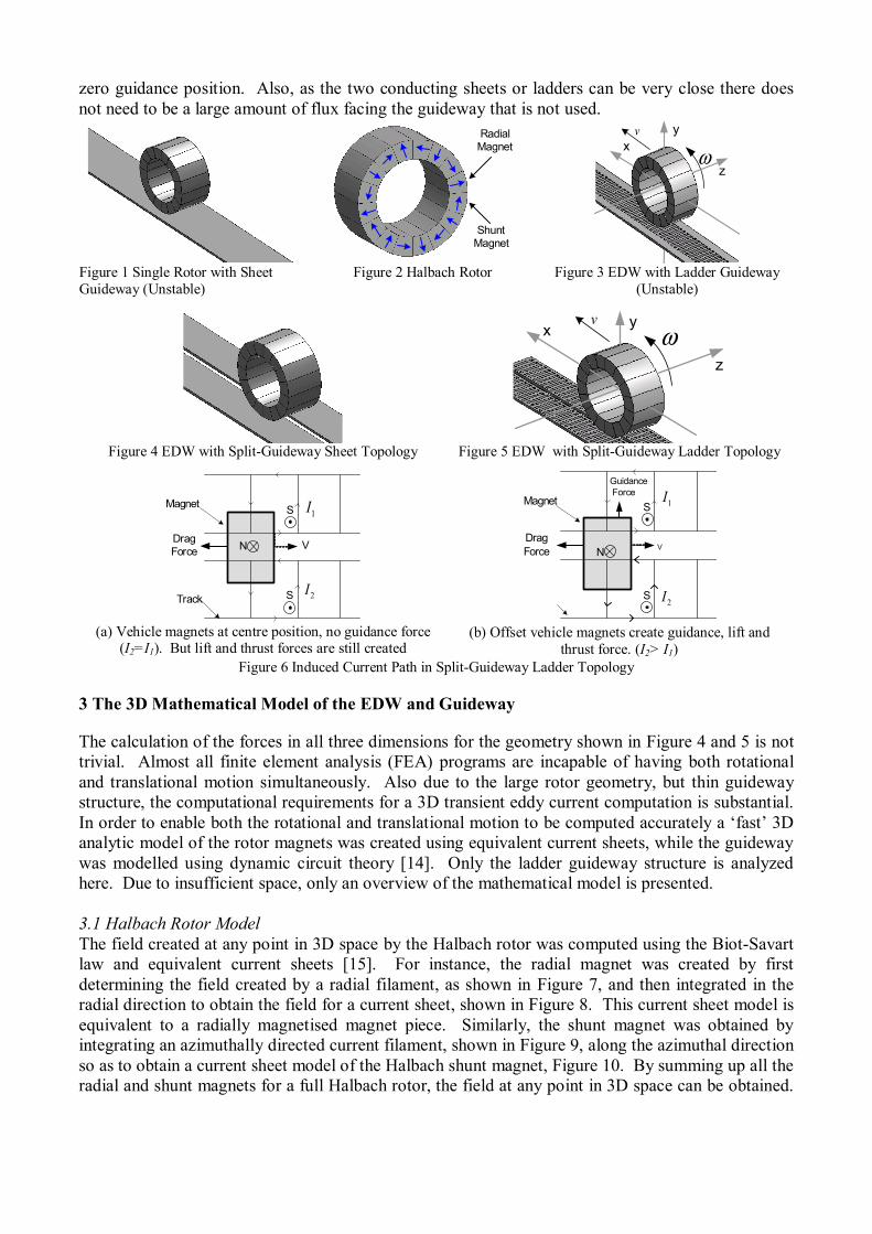
zero guidance position. Also, as the two conducting sheets or ladders can be very close there does not need to be a large amount of flux facing the guideway that is not used.
RadialMagnet
ShuntMagnet
y
z
x ωv
Figure 1 Single Rotor with Sheet Guideway (Unstable)
Figure 2 Halbach Rotor Figure 3 EDW with Ladder Guideway (Unstable)
Figure 4 EDW with Split-Guideway Sheet Topology
y
z
x ωv
Figure 5 EDW with Split-Guideway Ladder Topology
VN
S
DragForce
Track
Magnet
S
1I
2I
(a) Vehicle magnets at centre position, no guidance force
(I2=I1). But lift and thrust forces are still created
VN
S
DragForce
Magnet
S
Guidance Force
1I
2I
(b) Offset vehicle magnets create guidance, lift and thrust force. (I2> I1)
Figure 6 Induced Current Path in Split-Guideway Ladder Topology
3 The 3D Mathematical Model of the EDW and Guideway
The calculation of the forces in all three dimensions for the geometry shown in Figure 4 and 5 is not trivial. Almost all finite element analysis (FEA) programs are incapable of having both rotational and translational motion simultaneously. Also due to the large rotor geometry, but thin guideway structure, the computational requirements for a 3D transient eddy current computation is substantial. In order to enable both the rotational and translational motion to be computed accurately a ‘fast’ 3D analytic model of the rotor magnets was created using equivalent current sheets, while the guideway was modelled using dynamic circuit theory [14]. Only the ladder guideway structure is analyzed here. Due to insufficient space, only an overview of the mathematical model is presented. 3.1 Halbach Rotor Model The field created at any point in 3D space by the Halbach rotor was computed using the Biot-Savart law and equivalent current sheets [15]. For instance, the radial magnet was created by first determining the field created by a radial filament, as shown in Figure 7, and then integrated in the radial direction to obtain the field for a current sheet, shown in Figure 8. This current sheet model is equivalent to a radially magnetised magnet piece. Similarly, the shunt magnet was obtained by integrating an azimuthally directed current filament, shown in Figure 9, along the azimuthal direction so as to obtain a current sheet model of the Halbach shunt magnet, Figure 10. By summing up all the radial and shunt magnets for a full Halbach rotor, the field at any point in 3D space can be obtained.

An example of the radial and z directed field components above a 4 pole-pair Halbach rotor and the validation of the radial field component, using Ansoft’s Maxwell 3D, is shown in Figure 11 to 13.
z
eθ
ar
y
sθ
bb x
1
2
3
4
( , , )P r zθ
1θ
1dl
2dl2z
z
eθ
ar
y
sθb
b x
1
2
3
4eθ
dr
0M
34
2
( , , )P r zθ
z
y
bb
x
1
23
4inr
or
aθ
( , , )P r zθ
1dl
2dlor
z
y
bb
x
1
2
3
4inr
( , , )P r zθ
2dl4
Sθ
eθ
1
23
41dθ
Figure 7 Radial Magnet Filament
Figure 8 Equivalent Current Sheet Model for a Radial Magnet Piece
Figure 9 Azimuthal Magnet Filament
Figure 10 Equivalent Current Sheet Model for a Shunt Magnet Piece
050
100150
200250
300
-0.2
-0.1
0
0.1
0.2-1
-0.5
0
0.5
1
Theta [degrees]z-axis [m]
0 50 100 150 200-0.8
-0.6
-0.4
-0.2
0
0.2
0.4
0.6
0.8MatlabMaxwell
Figure 11 Halbach Rotor Field [T] in the Radial Direction
Figure 12 Halbach Rotor Field [T] in z-direction
Figure 13 Radial Magnet Flux Density [T]at z=20mm and r=105mm
3.1 Guideway Model The guideway was modelled by using dynamic circuit theory [14] in which the guideway is represented using lumped parameters:
[ ] [ ]de M i R idt
= + (1) dedtφ= − (2)
where [M] is the inductance matrix, [R] is the resistance matrix and e is a voltage column matrix computed from the changing Halbach rotor flux,φ , over each guideway loop. Equation (1) was solved for the current, i. The self and mutual inductance terms were computed using exact analytic equations for rectangular conducting bars [16] and using the concept of partial inductances [17]. 3.3 Computation of the Forces The forces in the air-gap were computed by integrating Maxwell’s stress tensors over a flat surface in the air-gap between the rotor and the guideway. The field components in the air-gap are composed of the field due to the magnets, Brotor and the field due to the induced guideway currents, Bguideway:
( , , ) ( , , ) ( , , )rotor guidewayx y z x y z x y z= +B B B (3)
The guideway field was computed using Biot-Savart’s law (using the same method that was used to find the magnet filament field). The stress tensor force equations are: [18]
Thrust Force: 0
1x y xS
F B B dxdzµ
= ∫ [N] (4)
Lift Force: ( )2 2 2
0
12y y x zS
F B B B dxdzµ
= − −∫ [N] (5)
Guidance Force: 0
1z y zS
F B B dxdzµ
= ∫ [N] (6)

The stress tensor force between the magnets was also computed and subtracted as this does not impart any force on the guideway. An illustration of the force density in the air gap at one particular instant of time for the split-guideway ladder is shown in Figure 14 to 16. The parameters used are given in Table 1. Since the force density is greater on the right side in Figure 16, restorative guidance forces are created.
3.2 Validation of the Complete Analytic Model with Transient Magsoft Flux 3D The Matlab model was validated using Magsoft Flux 3D transient solver that has rotational but no translational motion. An illustration of a meshed split-guideway FEA model is shown in Figure 17. Due to the massive computational requirements only a short guideway could be simulated using FEA. The suspension, thrust and guidance forces computed using both the FEA and Matlab model are shown in Figures 18 to 20. Some of the parameters used are shown in Table 1. The forces in Magsoft were computed using both virtual work and Lorentz force. As can be seen the Matlab model accurately computes the lift and guidance forces but somewhat under estimates the thrust force. The differences are due to assuming that the currents in the guideway are filaments when calculating the guideway field Bguideway, and not accounting for the skin effect.
Figure 14 Thrust Force Density Figure 15 Suspension Force Density Figure 16 Guidance Force Density
3.3 Including Translational Motion The translational motion of the EDW can be easily modelled in Matlab by moving the guideway at each time step. A 1.8m long track was used so as to ensure that steady state would be achieved. The
0 0.005 0.01 0.015 0.02 0.025 0.03-500
-450
-400
-350
-300
-250
-200
-150
-100
-50
0
Lorentz force, Magsoft
Virtual work, Magsoft
Matlab stress tensor, ω=1000RPM, v=0 translation, 31 loops
Matlab, ω=1000RPM, v=8m/s translation, 300 loops
Matlab,ω=6000 RPM, v=40m/s translation, 300 loops
Figure 17 Magsoft 3D FEA Model Figure 18 Suspension Force Comparison [N]
Table 1.
Outer radius 0.1 m Guideway conductivity
3.5×10⁷Sm-1
Track thickness 6 mm Magnet width 0.15 m Air gap 10 mm RPM 1000 rpm Rotor Offset 29 mm Split-guideway space 24 mm Track width 152 mm
0 0.005 0.01 0.015 0.02 0.025 0.03-100
-50
0
50
100
150
200
Lorentz force, Magsoft
Virtual work, Magsoft
Matlab stress tensor, ω=1000RPM, v=0 translation, 31 loops
Matlab, ω=1000RPM, v=8m/s translation, 300 loops
Matlab,ω=6000 RPM, v=40m/s translation, 300 loops
time [s] 0 0.005 0.01 0.015 0.02 0.025 0.03
0
20
40
60
80
100
120
Lorentz force, Magsoft
Virtual work, Magsoft
Matlab stress tensor, ω=1000RPM, v=0 translation, 31 loops
Matlab, ω=1000RPM, v=8m/s translation, 300 loops
Matlab,ω=6000 RPM, v=40m/s translation, 300 loops
time [s].
0 0.005 0.01 0.015 0.02 0.025 0.03
-1000
-800
-600
-400
-200
0
200
400
600
800
x Current, Loop 9 Track 1
Magsoft
Matlab
time [s]
Figure 19 Thrust Force Comparison [N] Figure 20 Guidance Force [N] Figure 21 Current in a Track Loop [A]

results for when the EDW is rotated at 1000RPM, which corresponds to 10.4ms-1 circumferential velocity, and also moved translationally at 8m/s is shown in Figures 18 to 20. As expected the forces decrease significantly because the relative change in flux seen by the track decreases. As a last example the simulation results for the case when the rotor has 6000RPM and is moving at 40ms-1 is also shown.
4 Conclusion
Preliminary results from a 3D Matlab model of a Halbach rotor rotating and moving translationally over an aluminium split-guideway ladder topology have been presented. The Matlab model has been validated using magnetostatic FEA models in Ansoft Maxwell 3D and transient FEA models in Magsoft 3D. Using a split-guideway structure it was confirmed that suspension, thrust and guidance force can be simultaneously obtained. Unlike the FEA model the Matlab model enables transient translational motion to be also modelled. The Matlab model could be further improved by accounting for the skin effect. It’s fast computational speed, relative to FEA, will enable future realistic design and control studies to be conducted. The only intrinsic damping for the EDW comes from the aerodynamic drag; thus, control of multiple EDW’s will be essential.
5 Acknowledgements
The authors would like to acknowledge the support provided by the member companies of the Wisconsin Electric Machines and Power Electronics Consortium (WEMPEC) at the University of Wisconsin-Madison. Also the authors would like to gratefully thank the Magsoft and Ansoft Corporation for the use of their FEA software.
6 References
[1] J. Bird, T.A. Lipo. A preliminary investigation of an electrodynamic wheel for simultaneously creating levitation and propulsion. in 18th International Conference on Magnetically Levitated Systems and Linear Drives. 2004. Shanghai, China. p. 316.
[2] H.J. Lever, Technical Assessment of Maglev System Concepts, Final Report by the Government Maglev System Assessment Team. 1998, CRREL-SR-98-12
[3] A. Cassat, C. Espanet. Swismetro combined propulsion with levitation and guidance. in 18th International Conference on Magnetically Levitated Systems and Linear Drives. 2004. Shanghai, China. p. 747.
[4] T. Murai, T. Sasakawa, Characteristics of SC coil configuration for EDS maglev to reduce leakage flux with strengthened magnetomotive force. 18th International Conference on Magnetically Levitated Systems and Linear Drives, 2004. 2: p. 966.
[5] J. He, D.M. Rote, Double-row loop-coil configuration for EDS maglev suspension, guidance, and electromagnetic guideway directional switching. IEEE T. Magn., 1993. 29(6): p. 2956.
[6] T. Barrows, et al., Aerodynamic Forces on Maglev Vehicles. 1992, Cambridge, MA, DOT/FRA/NMI-92/21 [7] T. Akinbiyi, P.E. Al-Rikabi, B.T. Ooi, A comparison of ladder and sheet guideways for electrodynamic levitation
of high speed vehicles,. IEEE T. Magn., 1976. 12(6): p. 879. [8] K.R. Davey, Designing with null flux coils. IEEE T. Magn., 1997. 33(5): p. 4327. [9] R.F. Post, D.D. Ryutov, The Inductrack Concept: a New Approach to Magnetic Levitation. 1996, Livermore, CA,
UCRL-ID-124115 [10] D.L. Atherton, A.R. Eastham, B.T. Ooi, Forces and moments for electrodynamic levitation systems - large-scale
test results and theory. IEEE T. Magn., 1978. 14(2): p. 59. [11] D.L. Atherton, A.R. Eastham, Flat guidance schemes for magnetically levitated high-speed guided ground
transport. J. Appl. Phys. , 1974. 45(3): p. 1398. [12] T. Sakamoto, A.R. Eastham, G.E. Dawson, Induced currents and forces for the split-guideway electrodynamic
levitation system. IEEE T. Magn., 1991. 27(6): p. 5004. [13] Y. Iwasa, Electromagnetic flight stability by model impedance simulation. J. Appl. Phys. , 1973. 44(2): p. 858. [14] J. He, D.M. Rote, H.T. Coffey, Applications of the dynamic circuit theory to maglev suspension systems. IEEE T.
Magn., 1993. 29(6): p. 4153. [15] D.K. Cheng, Field and Wave Electromagnetics. 1989: Addison-Wesley Publishing. [16] C. Hoer, C. Love, Exact inductance equations for rectangular conductors with applications to more complicated
geometries. Journal of Research of the National Bureau of Standards, 1965. 69C(2): p. 127. [17] E.B. Rosa, The self and mutual inductances of linear conductors. Bull. of the Bureau of Stand., 1908. 4(2): p. 301. [18] D.J. Griffiths, Introduction to Electrodynamics. 3rd ed. 1999: Prentice Hall.