electrodynamic wheel (edw) magnetic levitation using
TRANSCRIPT

Electrodynamic Wheel (EDW) Magnetic Levitation using COMSOL Multiphyiscs

Introduction
The mechanical rotation of a magnetic source such as a radially magnetized Halbach rotor above a passive conductive guideway, such as aluminum, will induce eddy-currents in the guideway (geometry in next slide). This will result in an opposing magnetic field being created that interacts with the source magnetic field to produce both lift and thrust/drag forces simultaneously
The production of the thrust or braking force depends on the relative slip speed defined as the difference between the circumferential speed, and the translational speed. If the circumferential speed is greater than the translational speed (for positive slip), a thrust force is generated and vice-versa.

Geometry of the EDW Maglev structure
Electrodynamic Wheel (EDW) maglev consists of a multi-pole Halbach rotor rotating and/or translationally moving over a conductive guideway.
The Halbach rotor and conducting guideway are separated by air-gap “g”.
The direction of magnetization is shown with a red-arrow in the Halbach rotor.
The lift and the thrust/drag forces are generated simultaneously.
m o x
e m
Slip r v
P
Where: vx: translational velocity vc: circumferential velocity ωm: mechanical angular frequency ωe : electrical angular frequency P: number of pole-pairs

Parameters and Material Properties
The parameters used in the model are shown in the table below. The parameters like inner and outer radii of the rotor, angular speed and translational velocity are defined here.
The material properties used in the model are listed below.
Material Electrical Conductivity (σ)
Relative permeability (μr)
Relative permittivity (ϵr)
Aluminum track 3.03e7[S/m] 1 1
Air 0 [S/m] 1 1

Modeling Approach
A 2D, Rotating Machinery, Magnetic Interface available in the AC/DC module is used to model the EDW.
The Rotating Machinery, Magnetic interface combines the Magnetic Fields and the Magnetic Fields, No Currents interfaces solving for both the Magnetic Vector and Scalar potentials.
The magnets are arranged in an Halbach array to concentrate the magnetic field on the outer surface of the rotor.
Velocity(Lorentz) term is used to define translational velocity of maglev (rotor) on to the Aluminum track.

Modeling Approach Contd….
In the geometry, two unions are created as shown in the figure below
Stationary domains
Rotating domains

The identity pair, created around the outer diameter of the rotor, is used to ensure continuity of the fields between the stationary and rotating domains. Continuity condition is then applied using this identity pair in the physics settings
Modeling Approach Contd….

A new cylindrical coordinate system is defined to model the magnetization of the magnets in radial and circumferential direction.
Ampere’s law domain conditions are used to assign magnetization to the magnets. Once such example is shown below.
Modeling Approach Contd….
Modeling Approach Contd….
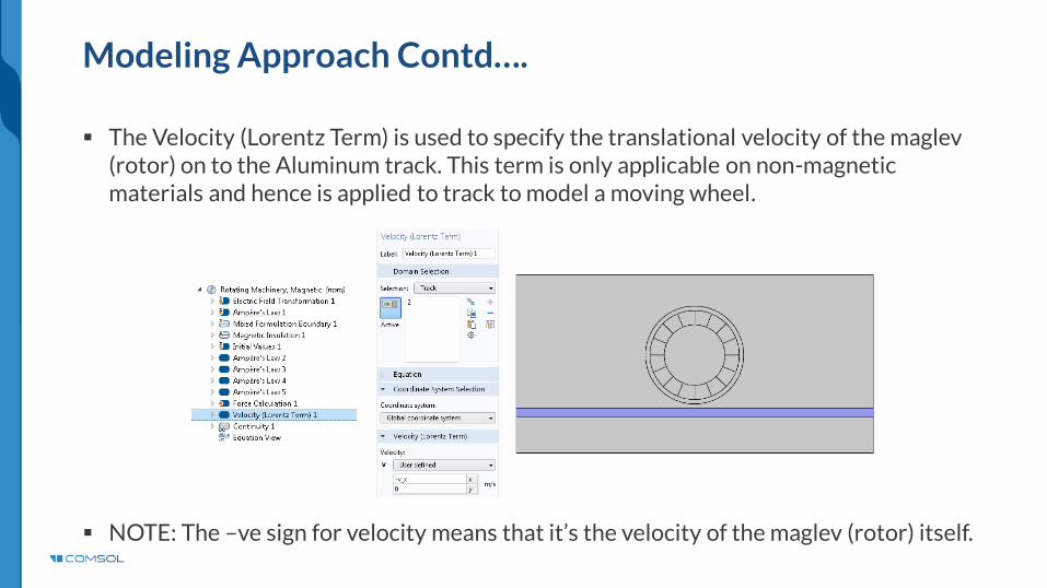
The Velocity (Lorentz Term) is used to specify the translational velocity of the maglev (rotor) on to the Aluminum track. This term is only applicable on non-magnetic materials and hence is applied to track to model a moving wheel.
NOTE: The –ve sign for velocity means that it’s the velocity of the maglev (rotor) itself.

Force Calculation
The Force on the track is calculated using the Maxwell’s Stress Tensor. Results are compared with the Lorentz forces calculated by integrating the Lorentz force terms over the track. Figure below shows the integration term and the variables defined to calculate the Lorentz forces.
NOTE: The –ve sign on expression means that the force are calculated on the maglev (rotor).

Meshing Sequence
Figure below shows the meshing sequence implemented. The mesh around the edges of the rotor magnets and the destination boundaries of the of the identity pair are made finer compared to the stationary part to resolve the field between the rotating and stationary part. Mapped meshing is used on the track to properly calculate the eddy currents. Mapped mesh is also used in the magnet pieces.

Results
A stationary study to get the initial values followed by time dependent study is performed to correctly account for the magnetic fields from permanent magnets.
Figure below shows the surface plots norm of the Magnetic Flux Density and Current Density at time=30ms. The contour plot shows the Magnetic vector potential

Results
Comparison of the Lift and Thrust forces on the track calculated using Maxwell’s Stress Tensor and the Lorentz force terms for a step change in
Comparison of lift forces on the track with Stress tensor and Lorentz Force method
Comparison of thrust forces on the track with Stress tensor and Lorentz Force method

Results: Change in Velocity
Animation of current density (in track) and magnetic flux density around with velocity changing from 0[m/s] to 100[m/s].

Results: Change in Velocity
Comparison of the Lift and Thrust forces on the track calculated using Maxwell’s Stress Tensor and the Lorentz force terms.
Comparison of thrust forces on the track with Stress tensor and Lorentz Force method
Comparison of lift forces on the track with Stress tensor and Lorentz Force method

References:
J. Bird, An investigation into the use of electrodynamic wheels for high-speed ground transportation. PhD thesis, University of Wisconsin-Madison, 2007.
N. Paudel, Dynamic suspension modeling of an eddy-current device: An application to Maglev. PhD thesis, University of North Carolina-Charlotte, NC, 2012.
S. Paul, Three-dimensional steady state and transient eddy current modeling. PhD thesis, University of North Carolina-Charlotte, NC, 2013.
N. Paudel, S. Paul, and J. Z. Bird, General 2-D steady-state force and power equations for a traveling time-varying magnetic source above a conductive plate , IEEE Transactions on Magnetics, 2012.
N. Paudel, S. Paul, and J. Z. Bird, General 2-D transient eddy current force equations for a magnetic source moving above a conductive plate, Progress In Electromagnetics Research B, 2012.

Conclusion
Magnetic Levitation using Electrodynamic Wheel has been modeled using a wheel made with permanent magnets arranged in an Halbach array. The wheel is rotated at certain angular velocity and the translational motion of the maglev (rotor) is included on the track using Velocity (Lorentz Term).
The Lift and Thrust forces are calculated using the Maxwell’s Stress Tensor method and the Lorentz Force terms. A comparison of forces calculated by these two methods is performed.
A close match in the values of forces between these two methods is obtained.