research article signal denoising method based on...
TRANSCRIPT

Research ArticleSignal Denoising Method Based on AdaptiveRedundant Second-Generation Wavelet for RotatingMachinery Fault Diagnosis
Na Lu,1 Guangtao Zhang,2 Yuanchu Cheng,3 and Diyi Chen4
1School of Water Conservancy & Environment, Zhengzhou University, Zhengzhou 450000, China2Henan Electric Power Research Institute, Zhengzhou 450000, China3School of Power and Mechanical Engineering, Wuhan University, Wuhan 430072, China4College of Water Resources and Architectural Engineering, Northwest A&F University, Yangling 712100, China
Correspondence should be addressed to Yuanchu Cheng; [email protected]
Received 17 January 2016; Revised 9 August 2016; Accepted 10 August 2016
Academic Editor: Stefan Balint
Copyright © 2016 Na Lu et al. This is an open access article distributed under the Creative Commons Attribution License, whichpermits unrestricted use, distribution, and reproduction in any medium, provided the original work is properly cited.
Vibration signal of rotating machinery is often submerged in a large amount of noise, leading to the decrease of fault diagnosisaccuracy. In order to improve the denoising effect of the vibration signal, an adaptive redundant second-generation wavelet(ARSGW) denoising method is proposed. In this method, a new index for denoising result evaluation (IDRE) is constructedfirst. Then, the maximum value of IDRE and the genetic algorithm are taken as the optimization objective and the optimizationalgorithm, respectively, to search for the optimal parameters of the ARSGW. The obtained optimal redundant second-generationwavelet (RSGW) is used for vibration signal denoising. After that, features are extracted from the denoised signal and then inputinto the support vectormachinemethod for fault recognition.The application result indicates that the proposed ARSGWdenoisingmethod can effectively improve the accuracy of rotating machinery fault diagnosis.
1. Introduction
At present, rotating machinery has been widely applied inindustrial field. Meanwhile, its safety and stability operat-ing problems have gained comprehensive attention [1, 2].Rotating machinery failure often causes equipment damage,significant economic losses, and even causalities. Therefore,its fault diagnosis is of great significance for ensuring thesafety and stability operation as well as the prevention ofcatastrophe accidents. Vibration signal processing and analy-sis are one of themost favoredmeans to diagnose the rotatingmachinery fault [3, 4]. However, because of the complicatedoperating conditions and harsh operating environment, thevibration signal is often submerged in a large amount of noise,which may decrease the accuracy of the fault diagnosis [5–7].Therefore, it is necessary to study an effective vibration signaldenoising method to improve the accuracy of the rotatingmachinery fault diagnosis.
Signal denoising problem has always been the hotspotin signal processing field. Up to now, various signal denois-ing methods have been developed to analyze the vibrationsignals, such as finite impulse response filter (FIR) [8],time-frequencymanifold [9], empirical mode decomposition(EMD) [10], curvelet transform [11], quantum Hadamardtransformation [12], wavelet [13], and multiwavelets [14].Among these methods, FIR and wavelet are two of themost popular time-frequency analysis tools. However, thefrequency response of FIR depends on its coefficients, whichis related to the cut-off frequency and the order of the filter[15]. Hence, the choice of cut-off frequency and order mayhave a great impact on the denoising result. Wavelet has beenwidely applied formechanical vibration signal denoising [16–18]. However, the denoising effect is influenced by the waveletbase function selection to a large extent [19]. Inappropriatebase function may lead to unsatisfactory denoising result.Furthermore, the existing wavelet base functions cannot
Hindawi Publishing CorporationMathematical Problems in EngineeringVolume 2016, Article ID 2727684, 10 pageshttp://dx.doi.org/10.1155/2016/2727684

2 Mathematical Problems in Engineering
change adaptively according to the characteristics of theacquired vibration signal. This may degrade the denoisingresult [20].
Second-generation wavelet (SGW) is a new wavelettheory that emerged in recent years. Compared with thetraditional wavelet, the construction of SGW avoids Fouriertransform. In addition, it has fast computational speed [21].Because of the advantages of SGW, it has been widely appliedin vibration signal processing field. For example, Li et al. [22,23] combined lifting wavelet with morphological wavelet toconstruct an adaptive morphological gradient lifting wavelet,which is used for bearing and gear vibration signal denoisingand feature extraction; Bao et al. [24] adopted lifting waveletfor weak fault feature extraction from vibration signal; Fanet al. [25] applied SGW to decompose bearing vibrationsignal and then input the result to independent componentanalysis (ICA) approach for fault diagnosis; Chen et al. [26]employed SGW to test and diagnose crack location of rotor;Bao et al. [27] applied two-dimensional lifting wavelet forrotatingmechanical vibration data compression, and so forth.Even though multiple achievements have been obtained,SGW suffers from some defects. Because the split and mergeoperations are needed in the SGW transformation process,frequency aliasing problem often emerged. This makes thedecomposition result contain fake frequency componentsand decreases the fault diagnosis accuracy.
To overcome the frequency aliasing problem, [24] ana-lyzed the reason why it appears and proposed a redundantsecond-generation wavelet (RSGW) method. RSGW trans-form does not include split and merge operations and thuscan overcome the frequency aliasing problem to a largeextent. Therefore, RSGW is superior to SGW in applicationto signal denoising. However, similar to the base functionof wavelet, the prediction operator length, update operatorlength, and decomposition level of RSGW should be prede-termined. In general, these parameters have a great impact onsignal denoising performance. But it is difficult to select themproperly.
In order to select the optimal parameters of RSGWaccording to the characteristics of signal and obtain afavorable denoising result, an adaptive redundant second-generation wavelet (ARSGW) denoising method for rotatingmachinery fault diagnosis is proposed in this paper. Thismethod is mainly composed of three phases. In the firstphase, parameters like the prediction operator length, updateoperator length, and decomposition level of RSGW areinitialized to some default values within their certain range.In the second phase, the optimal value of an index for signaldenoising result evaluation and the genetic algorithm aretaken as the optimization objective and the optimizationalgorithm, respectively, to search for the optimal values ofthese parameters. After that, the RSGWwith optimal param-eters is applied to vibration signal denoising for rotatingmachinery in the last phase. It can be seen that an effectiveindex for signal denoising result evaluation is essential foroptimal parameters searching in the second phase of thismethod. Signal-to-noise ratio (SNR) [28] is a commonly usedindex for evaluation of noise intensity in signal. However,it can only be used in the circumstance that the real signal
without noise component is known beforehand. Becausethe real signal component in the actual vibration signal isunavailable, SNR is not applicable for its denoising resultevaluation. Therefore, a new index for rotating machinerysignal denoising result evaluation (IDRE) is constructed inthis paper. Based on IDRE, the newly proposed method canenable the parameters of RSGW to change adaptively with thecharacteristics of the acquired vibration signal and improvethe signal denoising performance effectively.
The rest of this paper is arranged as follows. In Section 2,theory of SGW and RSGW is reviewed briefly. In Section 3, anew IDRE is constructed and the ARSGWdenoising methodis proposed. Then this method is applied for a hydroturbineunit vibration simulation signal denoising in Section 4 todemonstrate the effectiveness of the IDRE and the ability ofASGW to obtain an optimal denoising result. In Section 5,vibration signals of a rotatingmachinery system are denoised.Features in both time and frequency domains are extractedfrom the denoised signals and then input into the supportvector machine method for fault recognition to validate theability of ARSGWdenoisingmethod to improve the accuracyof rotating machinery fault diagnosis. Conclusions are givenin Section 6.
2. Redundant Second-Generation Wavelet
2.1. Summary of Second-Generation Wavelet Theory. As abranch of wavelet theory, SGW inherited its excellent charac-teristics of time-frequency location. Furthermore, SGW hashigher calculation efficiency and more clear principle andneeds lower space [24]. SGW transform includes decomposi-tion and reconstruction processes demonstrated in Figure 1.The decomposition process of SGW includes the followingsteps:
(1) Split: the signal 𝑋 = {𝑥[𝑛], 𝑛 ∈ 𝑍} is divided into twosubsets: the odd sample set 𝑋
𝑜= {𝑥𝑜[𝑛], 𝑛 ∈ 𝑍} and
the even sample set𝑋𝑒= {𝑥𝑒[𝑛], 𝑛 ∈ 𝑍}:
𝑥𝑜[𝑛] = 𝑥 [2𝑛 + 1] ,
𝑥𝑒[𝑛] = 𝑥 [2𝑛] .
(1)
(2) Predict: the prediction operator 𝑃 is used to predictthe odd sample set 𝑋
𝑜based on the even sample
set 𝑋𝑒. Then, the prediction error between 𝑥
𝑜[𝑛] and
𝑃(𝑋𝑒) gives the detail coefficients 𝑑[𝑛]:
𝑑 [𝑛] = 𝑥𝑜[𝑛] − 𝑃 (𝑋
𝑒) . (2)
(3) Update: use the update operator𝑈 to update the detailcoefficients𝐷 = {𝑑[𝑛], 𝑛 ∈ 𝑍} and add the result𝑈(𝐷)to 𝑥𝑒[𝑛]; the approximation coefficients 𝑐[𝑛] can be
obtained:
𝑐 [𝑛] = 𝑥𝑒[𝑛] + 𝑈 (𝐷) . (3)
After the above three steps, the detail coefficients𝐷 = {𝑑[𝑛], 𝑛 ∈ 𝑍} and the approximation coeffi-cients 𝐶 = {𝑐[𝑛], 𝑛 ∈ 𝑍} are obtained. Multilayerdecomposition of SGW can be carried out through theiteration of these three steps. Here, the prediction operator

Mathematical Problems in Engineering 3
Split −P Ux[n]
c[n]
d[n]+
+xe[n]
xo[n]
(a)
c[n]
d[n]
Merge−Ux[n]
P
+
+
xe[n]
xo[n]
(b)
Figure 1: Principle of SGW transform. (a) Decomposition of SGW. (b) Reconstruction of SGW.
+
+
cj−1[n]
cj[n]
−PjU U
jU
dj[n]
(a)
+
+
cj−1[n]
cj[n]
−PjUU
jU
dj[n]
1
2
1
2
cj−1c [n]
cj−1
d[n]
(b)
Figure 2: Principle of RSWG transform. (a) Decomposition of RSWG. (b) Reconstruction of RSWG.
𝑃 = [𝑝(1), 𝑝(2), . . . , 𝑝(𝑀)] and update operator 𝑈 =
[𝑢(1), 𝑢(2), . . . , 𝑢(𝑁)] are vectors with length of 𝑀 and𝑁, respectively. They can be designed by the interpolatingsubdivision method [29]. The obtained SGW is denoted as(𝑀,𝑁) SGW.
With the decomposition transform of SGW, the recon-struction transform of SGW can be implemented easily byinversing (1), (2), and (3).
2.2. Summary of Redundant Second-Generation Wavelet The-ory. Although SGW has got extensive application, it suffersfrom some defects. Because of the split and merge operationsin SGW transformation processes, frequency aliasing prob-lemmay be encountered.This will cause wrong estimation ofthe noise intensity in signal and degrade the denoising result.
RSGW does not need split and merge in its transforma-tion processes and thus can overcome the frequency aliasingproblem to a large extent. Assume that 𝑃𝑗
𝑈and 𝑈𝑗
𝑈are the
prediction operator and the update operator of RSGW at the2𝑗 scale, respectively; the initial prediction operator 𝑃0
𝑈=
[𝑝0
(1), 𝑝0
(2), . . . , 𝑝0
(𝑀)] and the initial update operator𝑈0
𝑈= [𝑢0
(1), 𝑢0
(2), . . . , 𝑢0
(𝑁)] can be calculated accordingto the prediction operator length𝑀 and the update operatorlength𝑁; then 𝑃𝑗
𝑈and 𝑈𝑗
𝑈can be calculated as [27]
𝑃𝑗
𝑈= [𝑝0
(1) , 0, . . . , 0⏟⏟⏟⏟⏟⏟⏟⏟⏟⏟⏟⏟⏟
2𝑗−1
, 𝑝0
(2) , 0, . . . , 0⏟⏟⏟⏟⏟⏟⏟⏟⏟⏟⏟⏟⏟
2𝑗−1
, 𝑝0
(3) , . . . ,
𝑝0
(𝑀 − 1) , 0, . . . , 0⏟⏟⏟⏟⏟⏟⏟⏟⏟⏟⏟⏟⏟
2𝑗−1
, 𝑝0
(𝑀)] ,
𝑈𝑗
𝑈= [𝑢0
(1) , 0, . . . , 0⏟⏟⏟⏟⏟⏟⏟⏟⏟⏟⏟⏟⏟
2𝑗−1
, 𝑢0
(2) , 0, . . . , 0⏟⏟⏟⏟⏟⏟⏟⏟⏟⏟⏟⏟⏟
2𝑗−1
, 𝑢0
(3) , . . . ,
𝑢0
(𝑁 − 1) , 0, . . . , 0⏟⏟⏟⏟⏟⏟⏟⏟⏟⏟⏟⏟⏟
2𝑗−1
, 𝑢0
(𝑁)] .
(4)
The principle of RSGW transform at 2𝑗 scale is shown inFigure 2. And the decomposition equation of RSGW at 2𝑗scale is expressed as
𝑑𝑗
[𝑛] = 𝑐𝑗−1
[𝑛] − 𝑃𝑗
𝑈(𝐶𝑗−1
) ,
𝑐𝑗
[𝑛] = 𝑐𝑗−1
[𝑛] + 𝑈𝑗
𝑈(𝐷𝑗
) .
(5)
Correspondingly, the reconstruction equation of RSGWat 2𝑗 scale is expressed as
𝑐𝑗−1
𝑐[𝑛] = 𝑐
𝑗
[𝑛] − 𝑈𝑗
𝑈(𝐷𝑗
)
𝑐𝑗−1
𝑑[𝑛] = 𝑑
𝑗
[𝑛] + 𝑃𝑗
𝑈(𝐶𝑗−1
𝑐)
𝑐𝑗−1
[𝑛] =1
2𝑐𝑗−1
𝑐[𝑛] +
1
2𝑐𝑗−1
𝑑[𝑛] .
(6)
3. Signal Denoising Method Based on AdaptiveRedundant Second-Generation Wavelet
Asmentioned above, RSGW is superior to SGW in the aspectof frequency aliasing problem. However, the prediction oper-ator length𝑀, update operator length𝑁, and decomposition
4 Mathematical Problems in Engineering
Input the acquired signal x[n] and initialize i = 0
Assign some default values to M, N, and L
Carry out L-layer RSGW decomposition
Reconstruct the signal
Calculate the IDRE of the reconstructed signal, and i = i + 1
Are the evolutional generations reached?
Yes
No
Apply thresholding to the obtained detail coefficients
Calculate the prediction operator and update operator
Output M, N, L, and the denoised signal
Geneticalgorithm
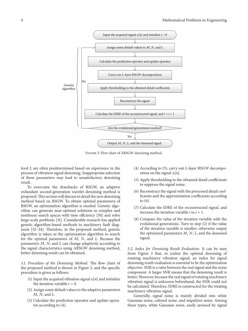
Figure 3: Flow chart of ARSGW denoising method.
level 𝐿 are often predetermined based on experience in theprocess of vibration signal denoising. Inappropriate selectionof these parameters may lead to unsatisfactory denoisingresult.
To overcome the drawbacks of RSGW, an adaptiveredundant second-generation wavelet denoising method isproposed.This sectionwill discuss in detail the newdenoisingmethod based on RSGW. To obtain optimal parameters ofRSGW, an optimization algorithm is needed. Genetic algo-rithm can generate near-optimal solutions in complex andnonlinear search spaces with time efficiency [30] and solvelarge-scale problems [31]. Considerable research has appliedgenetic algorithm-based methods to machinery fault diag-nosis [32–34]. Therefore, in the proposed method, geneticalgorithm is taken as the optimization algorithm to searchfor the optimal parameters of 𝑀, 𝑁, and 𝐿. Because theparameters𝑀, 𝑁, and 𝐿 can change adaptively according tothe signal characteristics using ARSGW denoising method,better denoising result can be obtained.
3.1. Procedure of the Denoising Method. The flow chart ofthe proposed method is shown in Figure 3, and the specificprocedure is given as follows:
(1) Input the acquired vibration signal 𝑥[𝑛] and initializethe iteration variable 𝑖 = 0.
(2) Assign some default values to the adaptive parameters𝑀,𝑁, and 𝐿.
(3) Calculate the prediction operator and update opera-tor according to (4).
(4) According to (5), carry out 𝐿-layer RSGW decompo-sition on the signal 𝑥[𝑛].
(5) Apply thresholding to the obtained detail coefficientsto suppress the signal noise.
(6) Reconstruct the signal with the processed detail coef-ficients and the approximation coefficients accordingto (6).
(7) Calculate the IDRE of the reconstructed signal, andincrease the iteration variable 𝑖 to 𝑖 + 1.
(8) Compare the value of the iteration variable with theevolutional generations. Turn to step (2) if the valueof the iteration variable is smaller; otherwise outputthe optimized parameters𝑀,𝑁, 𝐿, and the denoisedsignal.
3.2. Index for Denoising Result Evaluation. It can be seenfrom Figure 3 that, to realize the optimal denoising ofrotating machinery vibration signal, an index for signaldenoising result evaluation is essential to be the optimizationobjective. SNR is a ratio between the real signal and the noisecomponent. A larger SNR means that the denoising result isbetter. However, because the real signal of rotatingmachineryvibration signal is unknown beforehand, the SNR could notbe calculated.Therefore, IDRE is constructed for the rotatingmachinery vibration signal.
Generally, signal noise is mainly divided into whiteGaussian noise, colored noise, and impulsive noise. Amongthese types, white Gaussian noise, easily aroused by signal
Mathematical Problems in Engineering 5
recording device and transmission system [35], is commonlycontained in vibration signal. Numerous methods have beeninvited into denoising of the signal contaminated with whiteGaussian noise, such as EMD [10], wavelet [13], and multi-wavelets [14]. The denoising method proposed in this paperis also mainly applied to denoising of white noise.
Assume that the acquired vibration signal 𝑥[𝑛] is com-posed of the real signal 𝑓[𝑛] and white Gaussian noisecomponent 𝜀[𝑛]; namely, 𝑥[𝑛] = 𝑓[𝑛] + 𝜀[𝑛]; then, theautocorrelation function of 𝑥[𝑛] can be expressed as
𝑟𝑥[𝑚] =
1
𝑁
𝑁
∑
𝑛=1
(𝑓 [𝑛] + 𝜀 [𝑛]) (𝑓 [𝑛 + 𝑚] + 𝜀 [𝑛 + 𝑚])
= 𝑟𝑓[𝑚] + 𝑟
𝑓𝜀[𝑚] + 𝑟
𝜀𝑓[𝑚] + 𝑟
𝜀[𝑚] ,
(7)
where 𝑟𝑓[𝑚] and 𝑟
𝜀[𝑚] are the autocorrelation functions of
𝑓[𝑛] and 𝜀[𝑛], respectively, and 𝑟𝑓𝜀[𝑚] and 𝑟
𝜀𝑓[𝑚] are the
cross correlation functions of 𝑓[𝑛] and 𝜀[𝑛], respectively.Analyzing (7), the following can be known:
(1) The noise component 𝜀[𝑛] is random and irrelevantwith the real signal 𝑓[𝑛]. Hence, 𝑟
𝑓𝜀[𝑚] and 𝑟
𝜀𝑓[𝑚]
are almost equal to zero; the maximum value of 𝑟𝜀[𝑚]
appears at𝑚 = 0 and as𝑚 increases, the value of 𝑟𝜀[𝑚]
decreases rapidly.
(2) For a rotating machinery signal, 𝑓[𝑛] is mainly com-posed of period signal components, and so is 𝑟
𝑓[𝑚].
In addition, when 𝑓[𝑛] contains signal componentwith the period of 𝑇, 𝑟
𝑓[𝑚] has maximum values at
𝑚 = 0, 𝑇, 2𝑇, . . ..
Considering the above analysis, at the point𝑚 = 0, 𝑟𝑥[𝑚]
has amaximumvalue 𝑟max1𝑥
, and the value of 𝑟max1𝑥
is related tothe real signal 𝑓[𝑛] and the intensity of the noise component𝜀[𝑛].When𝑓[𝑛] is fixed, themore intense the noise, the larger𝑟max1𝑥
will be. Suppose that 𝑟max2𝑥
is the secondary maximumvalue of 𝑟
𝑥[𝑚]. Since as𝑚 increases from 0, the value of 𝑟
𝜀[𝑚]
decreases rapidly, 𝑟max2𝑥
mainly depends on 𝑟𝑓[𝑚] and related
to the real signal 𝑓[𝑛]. Hence, when 𝑓[𝑛] is fixed, 𝑟max2𝑥
keepsnearly the same. Therefore, IDRE is constructed as
IDRE =𝑟max2𝑥
𝑟max1𝑥
. (8)
It can be concluded from (8) that the fewer the noisecomponents the signal contains, the better the denoisingresult, and the larger the value of IDRE.
4. Simulation Signal Denoising
4.1. Construction of Hydroturbine Unit Vibration SimulationSignal. Assume the rotating frequency 𝑓 of a hydroturbineunit vibration signal is 1.25Hz. According to the characteris-tics of hydroturbine unit vibration signal, a signal function,
Table 1: Settings of some relevant parameters used in geneticalgorithm.
Parameters ValuesDecomposition layer 𝐿 Integer within [1, 6]Prediction operator length𝑀 Even number within [2, 14]Update operator length𝑁 Even number within [2, 14]Population scale 30Evolution generation 20Probability of crossover 0.8Probability of mutation 0.02
composed of 0.2 ∼ 0.45𝑓, 𝑓, 2𝑓, 3𝑓, and 4𝑓 signal compo-nents, is given as
𝑓 (𝑡) = 20 sin (2.5𝜋𝑡) + 4.5 sin (5𝜋𝑡) + 2.55 sin (7.5𝜋𝑡)
+ 1.5 sin (10𝜋𝑡) + 0.4 sin (0.5𝜋𝑡)
+ 0.3 sin (0.75𝜋𝑡) .
(9)
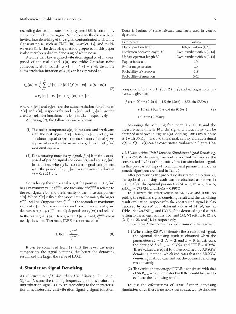
Assuming the sampling frequency is 2048Hz and themeasurement time is 10 s, the signal without noise can beobtained as shown in Figure 4(a). Adding Gauss white noise𝜀(𝑡) with SNRin = 18 db to this signal, a noisy vibration signal𝑥(𝑡) = 𝑓(𝑡)+ 𝜀(𝑡) can be constructed as shown in Figure 4(b).
4.2. Hydroturbine Unit Vibration Simulation Signal Denoising.The ARSGW denoising method is adopted to denoise theconstructed hydroturbine unit vibration simulation signal.In this process, settings of some relevant parameters used ingenetic algorithm are listed in Table 1.
After performing the procedure illustrated in Section 3.1,the optimal denoising result can be obtained as shown inFigure 4(c). The optimal parameters𝑀 = 2, 𝑁 = 2, 𝐿 = 5,SNRout = 27.3924, and IDRE = 0.9987.
To illustrate the effectiveness of ARSGW and IDRE ongetting the optimal signal denoising result and the denoisingresult evaluation, respectively, the constructed signal is alsodenoised by RSGW with different values of 𝑀, 𝑁, and 𝐿.Table 2 shows SNRout and IDRE of the denoised signal with 𝐿setting to the integer within [1, 6] and (𝑀,𝑁) setting to (2, 2),(2, 4), (4, 2), and (4, 4), respectively.
From Table 2, the following conclusions can be reached:
(1) When using RSGW to denoise the constructed signal,the optimal denoising result is obtained when theparameters𝑀 = 2, 𝑁 = 2, and 𝐿 = 5. In this case,the obtained SNRout = 27.3924 and IDRE = 0.9987.These values are equal to those obtained by ARSGWdenoising method, which indicates that the ARSGWdenoising method can find out the optimal denoisingresult exactly.
(2) The variation tendency of IDRE is consistent with thatof SNRout, which indicates the IDRE could be used toevaluate the denoising result.
To test the effectiveness of IDRE further, denoisingsimulationwhen there is no noise was conducted. To simulate
6 Mathematical Problems in EngineeringA
mpl
itude
−40−20
02040
0 0.2 0.4 0.6 0.8 1 1.2 1.4 1.6 1.8 2Sampling point ×104
(a)
Am
plitu
de
−40−20
02040
0 0.2 0.4 0.6 0.8 1 1.2 1.4 1.6 1.8 2Sampling point ×104
(b)
Am
plitu
de
0 0.2 0.4 0.6 0.8 1 1.2 1.4 1.6 1.8 2−40−20
02040
Sampling point ×104
(c)
Figure 4: Hydroturbine unit vibration simulation signal denoisingbased on ARSGW denoising method. (a) Real signal, (b) noisysignal, and (c) denoised signal.
the no-noise condition, SNRin was set to 1000, and otherparameters were set as the optimal ones obtained above. Theresult shows that the value of IDRE equals 1.This is consistentwith (8) that when there is no noise, 𝑟max1
𝑥and 𝑟max2𝑥
are equal.Compared with SNR, because IDRE can be calculated
without needing to know the real signal beforehand, itis suitable not only to simulation signal denoising resultevaluation but also to actual vibration signal denoising resultevaluation. Therefore, the maximum value of IDRE can betaken as the optimization objective when ARSGW denoisingmethod is adopted for rotating machinery vibration signaldenoising.
5. Vibration Fault Diagnosis for RotatingMachinery
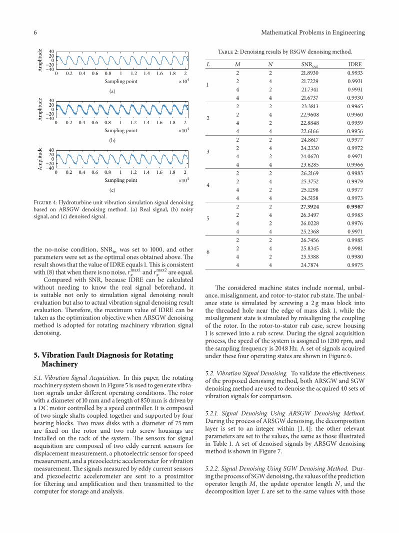
5.1. Vibration Signal Acquisition. In this paper, the rotatingmachinery system shown in Figure 5 is used to generate vibra-tion signals under different operating conditions. The rotorwith a diameter of 10mm and a length of 850mm is driven bya DC motor controlled by a speed controller. It is composedof two single shafts coupled together and supported by fourbearing blocks. Two mass disks with a diameter of 75mmare fixed on the rotor and two rub screw housings areinstalled on the rack of the system. The sensors for signalacquisition are composed of two eddy current sensors fordisplacement measurement, a photoelectric sensor for speedmeasurement, and a piezoelectric accelerometer for vibrationmeasurement. The signals measured by eddy current sensorsand piezoelectric accelerometer are sent to a proximitorfor filtering and amplification and then transmitted to thecomputer for storage and analysis.
Table 2: Denoising results by RSGW denoising method.
𝐿 𝑀 𝑁 SNRout IDRE
1
2 2 21.8930 0.99332 4 21.7229 0.99314 2 21.7341 0.99314 4 21.6737 0.9930
2
2 2 23.3813 0.99652 4 22.9608 0.99604 2 22.8848 0.99594 4 22.6166 0.9956
3
2 2 24.8617 0.99772 4 24.2330 0.99724 2 24.0670 0.99714 4 23.6285 0.9966
4
2 2 26.2169 0.99832 4 25.3752 0.99794 2 25.1298 0.99774 4 24.5158 0.9973
5
2 2 27.3924 0.99872 4 26.3497 0.99834 2 26.0228 0.99764 4 25.2368 0.9971
6
2 2 26.7456 0.99852 4 25.8345 0.99814 2 25.5388 0.99804 4 24.7874 0.9975
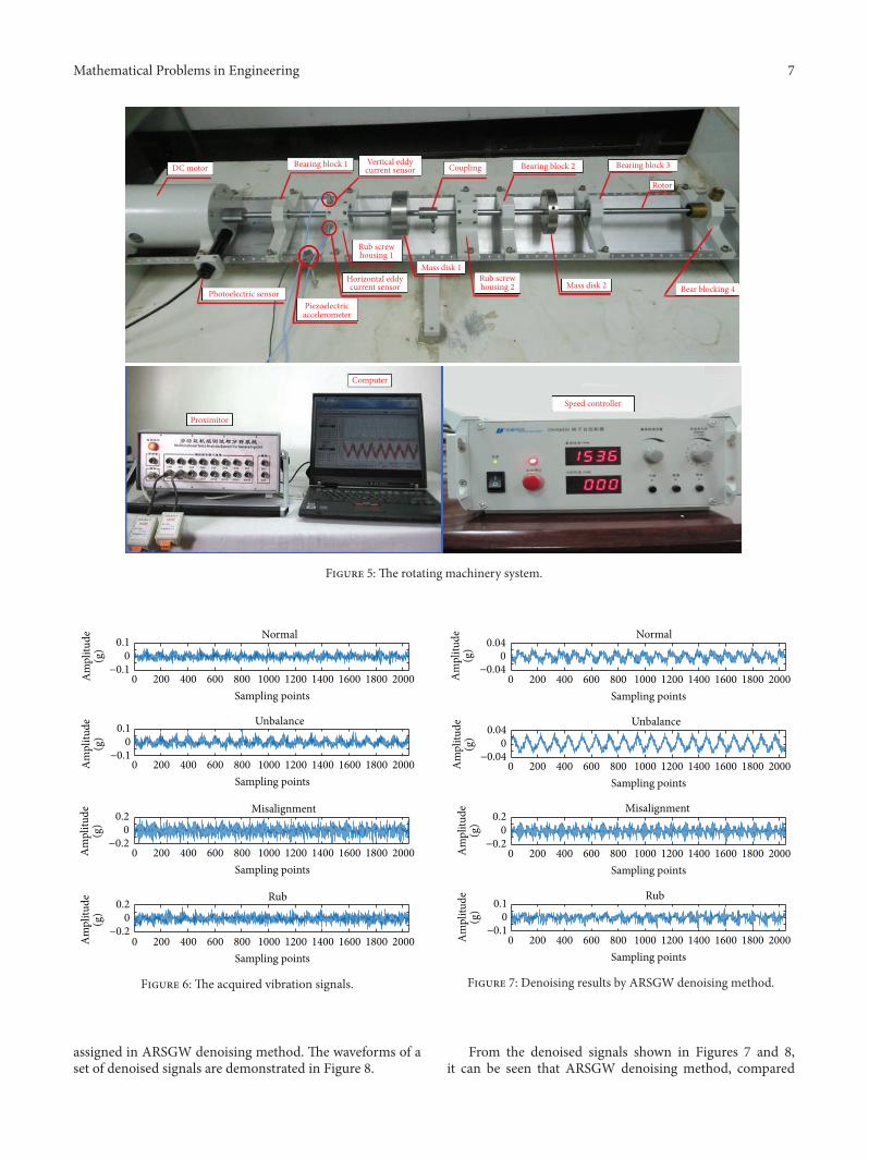
The considered machine states include normal, unbal-ance, misalignment, and rotor-to-stator rub state. The unbal-ance state is simulated by screwing a 2 g mass block intothe threaded hole near the edge of mass disk 1, while themisalignment state is simulated by misaligning the couplingof the rotor. In the rotor-to-stator rub case, screw housing1 is screwed into a rub screw. During the signal acquisitionprocess, the speed of the system is assigned to 1200 rpm, andthe sampling frequency is 2048Hz. A set of signals acquiredunder these four operating states are shown in Figure 6.
5.2. Vibration Signal Denoising. To validate the effectivenessof the proposed denoising method, both ARSGW and SGWdenoising method are used to denoise the acquired 40 sets ofvibration signals for comparison.
5.2.1. Signal Denoising Using ARSGW Denoising Method.During the process of ARSGWdenoising, the decompositionlayer is set to an integer within [1, 4]; the other relevantparameters are set to the values, the same as those illustratedin Table 1. A set of denoised signals by ARSGW denoisingmethod is shown in Figure 7.
5.2.2. Signal Denoising Using SGW Denoising Method. Dur-ing the process of SGWdenoising, the values of the predictionoperator length 𝑀, the update operator length 𝑁, and thedecomposition layer 𝐿 are set to the same values with those
Mathematical Problems in Engineering 7
DC motor Bearing block 1 Vertical eddycurrent sensor Coupling Bearing block 2 Bearing block 3
Bear blocking 4
Rotor
Mass disk 2Rub screwhousing 2
Mass disk 1
Rub screwhousing 1
Horizontal eddycurrent sensor
Piezoelectricaccelerometer
Photoelectric sensor
Proximitor
Computer
Speed controller
Figure 5: The rotating machinery system.
−0.10
0.1 Normal
−0.10
0.1 Unbalance
−0.20
0.2 Misalignment
−0.20
0.2
0 200 400 600 800 1000 1200 1400 1600 1800 2000Sampling points
0 200 400 600 800 1000 1200 1400 1600 1800 2000Sampling points
0 200 400 600 800 1000 1200 1400 1600 1800 2000Sampling points
0 200 400 600 800 1000 1200 1400 1600 1800 2000Sampling points
Am
plitu
de(g
)A
mpl
itude
(g)
Am
plitu
de(g
)A
mpl
itude
(g)
Rub
Figure 6: The acquired vibration signals.
assigned in ARSGW denoising method. The waveforms of aset of denoised signals are demonstrated in Figure 8.
−0.040
0.04Normal
−0.040
0.04Unbalance
−0.20
0.2Misalignment
−0.10
0.1Rub
Am
plitu
de(g
)A
mpl
itude
(g)
Am
plitu
de(g
)A
mpl
itude
(g)
0 200 400 600 800 1000 1200 1400 1600 1800 2000Sampling points
0 200 400 600 800 1000 1200 1400 1600 1800 2000Sampling points
0 200 400 600 800 1000 1200 1400 1600 1800 2000Sampling points
0 200 400 600 800 1000 1200 1400 1600 1800 2000Sampling points
Figure 7: Denoising results by ARSGW denoising method.
From the denoised signals shown in Figures 7 and 8,it can be seen that ARSGW denoising method, compared

8 Mathematical Problems in Engineering
Normal
−0.050
0.05Unbalance
Misalignment
−0.10
0.1 Rub
Am
plitu
de(g
)
−0.10
0.1
Am
plitu
de(g
)A
mpl
itude
(g)
−0.050
0.05
Am
plitu
de(g
)
0 200 400 600 800 1000 1200 1400 1600 1800 2000Sampling points
0 200 400 600 800 1000 1200 1400 1600 1800 2000Sampling points
0 200 400 600 800 1000 1200 1400 1600 1800 2000Sampling points
0 200 400 600 800 1000 1200 1400 1600 1800 2000Sampling points
Figure 8: Denoising results by SGW denoising method.
Table 3: Classification accuracy.
Denoising method Normal Unbalance Misalignment RubARSGW 100% 100% 100% 90%SGW 90% 95 95% 90%
with SWG denoising method, can suppress more noisecomponents and make the periodic features of the signalmore obvious; furthermore, the difference among the sig-nals under the four operating states denoised by ARSGWdenoising method becomes larger, which is beneficial to theimprovement of the fault diagnosis accuracy.
5.3. Rotating Machinery Fault Diagnosis. To further validatethe ability of ARSGW denoising method on improvingthe accuracy of the rotating machinery fault diagnosis, thecommonly used support vector machine method [36] isapplied for the four operating states’ classification.
Firstly, features, including means, variances, 1𝑓, 2𝑓, and3𝑓, are extracted from the 40 sets of signals denoised byARSGW and SGW denoising method. Then, features of 20sets of denoised signals are used to train the support vectormachine and those of the other 20 sets are used for test.Table 3 illustrates the classification accuracy of the fouroperating states using ARSGW and SGW denoising method,respectively.
Table 3 shows that the classification result adoptingARSGWas the denoisingmethod is better than that adoptingSGW as the denoising method. This indicates that theproposed ARSGWdenoisingmethod can effectively improvethe accuracy of the rotating machinery fault diagnosis.
6. Conclusions
The vibration signal denoising effect directly affects the rotat-ing machinery fault diagnosis performance. In this paper,a new IDRE is constructed, and based on IDRE, ARSGWdenoising method is proposed for rotating machinery vibra-tion signal denoising. The application of ARSGW denoisingmethod on the vibration signal denoising of a rotatingmachinery system gets a better result than that obtainedby SGW denoising method. Moreover, after inputting theextracted features from the denoised signal into supportvector machine method for classification, the result showsthat the recognition rate using ARSGW denoising methodis higher than that using SGW denoising method. Therefore,ARSGW denoising method can effectively improve the accu-racy of rotating machinery vibration fault diagnosis.
ARSGWdenoisingmethod, comparedwith SGWdenois-ing method, can be applied to denoise rotating machineryvibration signal adaptively and obtain optimal denoisingresults. The newly constructed IDRE, verified to be effectivein evaluating the vibration signal denoising result for rotatingmachinery, also provides some reference for signal denoisingof other kinds of machinery.
Competing Interests
The authors declare that there is no conflict of interestsregarding the publication of this manuscript.
Authors’ Contributions
Na Lu and Guangtao Zhang contributed equally to this work.
Acknowledgments
The authors acknowledge the financial support from theNational Natural Science Foundation of China under Grantno. 51609203 and from the Fundamental Research Funds forthe Central Universities under Grant no. 2014BSJJ053.
References
[1] C. Zhang, B. Li, B. Chen, H. Cao, Y. Zi, and Z. He, “Weakfault signature extraction of rotating machinery using flexibleanalytic wavelet transform,” Mechanical Systems and SignalProcessing, vol. 64-65, pp. 162–187, 2015.
[2] L. Ming, L. Fucai, J. Beibei, B. Huiyu, L. Hongguang, andM. Guang, “Multi-fault diagnosis of rotor system based ondifferential-based empirical mode decomposition,” Journal ofVibration and Control, vol. 21, no. 9, pp. 1821–1837, 2015.
[3] N. Li, J. Yang, R. Zhou, and Q. Wang, “Knock detection inspark ignition engines using a nonlinear wavelet transform ofthe engine cylinder head vibration signal,”Measurement Scienceand Technology, vol. 25, no. 11, Article ID 115002, 2014.
[4] W. Li, Z. Zhu, F. Jiang, G. Zhou, and G. Chen, “Fault diagnosisof rotating machinery with a novel statistical feature extractionand evaluationmethod,”Mechanical Systems and Signal Process-ing, vol. 50-51, pp. 414–426, 2015.

Mathematical Problems in Engineering 9
[5] W. Du, Y. Li, J. Yuan, and C. Liu, “Denoising with advancedstepwise false discovery rate control and its application to faultdiagnosis,”Measurement, vol. 45, no. 6, pp. 1515–1526, 2012.
[6] Y. Wang, Z. He, and Y. Zi, “Enhancement of signal denoisingand multiple fault signatures detecting in rotating machineryusing dual-tree complex wavelet transform,” Mechanical Sys-tems and Signal Processing, vol. 24, no. 1, pp. 119–137, 2010.
[7] W. He, Y. Zi, B. Chen, S. Wang, and Z. He, “Tunable Q-factorwavelet transform denoising with neighboring coefficients andits application to rotating machinery fault diagnosis,” ScienceChina Technological Sciences, vol. 56, no. 8, pp. 1956–1965, 2013.
[8] J. Tian, C. Morillo, M. H. Azarian, and M. Pecht, “Motorbearing fault detection using spectral kurtosis-based featureextraction coupled with K-nearest neighbor distance analysis,”IEEE Transactions on Industrial Electronics, vol. 63, no. 3, pp.1793–1803, 2016.
[9] Q. He, X.Wang, and Q. Zhou, “Vibration sensor data denoisingusing a time-frequencymanifold formachinery fault diagnosis,”Sensors, vol. 14, no. 1, pp. 382–402, 2013.
[10] Y. Kopsinis and S. McLaughlin, “Development of EMD-baseddenoising methods inspired by wavelet thresholding,” IEEETransactions on Signal Processing, vol. 57, no. 4, pp. 1351–1362,2009.
[11] A. Nicknam, M. H. Hosseini, and A. Bagheri, “Damagedetection and denoising in two-dimensional structures usingcurvelet transform by wrapping method,” Archive of AppliedMechanics, vol. 81, no. 12, pp. 1915–1924, 2011.
[12] Y. Chen, P. Zhang, Z. Wang, W. Yang, and Y. Yang, “Denois-ing algorithm for mechanical vibration signal using quantumHadamard transformation,”Measurement, vol. 66, pp. 168–175,2015.
[13] G. S. Vijay, H. S. Kumar, P. P. Srinivasa, N. S. Sriram, andR. B. K. N. Rao, “Evaluation of effectiveness of wavelet baseddenoising schemes using ANN and SVM for bearing conditionclassification,”Computational Intelligence andNeuroscience, vol.2012, Article ID 582453, 12 pages, 2012.
[14] H. Sun, K. Li, H. Wang, P. Chen, and Y. Cao, “Intelligentmechanical fault diagnosis based on multiwavelet adaptivethreshold denoising and MPSO,” Mathematical Problems inEngineering, vol. 2014, Article ID 142795, 15 pages, 2014.
[15] S. De Ridder, X. Neyt, N. Pattyn, and P.-F. Migeotte, “Compar-ison between EEMD, wavelet and FIR denoising: influence onevent detection in impedance cardiography,” in Proceedings ofthe 33rd Annual International Conference of the IEEE Engineer-ing in Medicine and Biology Society (EMBS ’11), pp. 806–809,IEEE, Boston, Mass, USA, September 2011.
[16] J.-L. Lin, J. Y.-C. Liu, C.-W. Li, L.-F. Tsai, and H.-Y. Chung,“Motor shaft misalignment detection using multiscale entropywith wavelet denoising,” Expert Systems with Applications, vol.37, no. 10, pp. 7200–7204, 2010.
[17] X. Chiementin, B. Kilundu, L. Rasolofondraibe, S. Crequy,and B. Pottier, “Performance of wavelet denoising in vibrationanalysis: highlighting,” Journal of Vibration and Control, vol. 18,no. 6, pp. 850–858, 2012.
[18] Y. Chen, Y. Zi, H. Cao, Z. He, and H. Sun, “A data-driventhreshold for wavelet sliding window denoising in mechanicalfault detection,” Science China Technological Sciences, vol. 57, no.3, pp. 589–597, 2014.
[19] R. R. Coifman and D. L. Donoho, “Translation-invariant de-noising,” in Wavelets and Statistics, vol. 103 of Lecture Notes inStatistics, pp. 1–26, Springer, New York, NY, USA, 1995.
[20] N. Lu, Z. Xiao, and O. P. Malik, “Feature extraction usingadaptive multiwavelets and synthetic detection index for rotorfault diagnosis of rotating machinery,” Mechanical Systems andSignal Processing, vol. 52-53, no. 1, pp. 393–415, 2015.
[21] Z. Liu, Y. Mi, and Y. Mao, “An improved real-time denoisingmethod based on lifting wavelet transform,” MeasurementScience Review, vol. 14, no. 3, pp. 152–159, 2014.
[22] B. Li, P.-L. Zhang, S.-S.Mi, R.-X.Hu, andD.-S. Liu, “An adaptivemorphological gradient lifting wavelet for detecting bearingdefects,” Mechanical Systems and Signal Processing, vol. 29, pp.415–427, 2012.
[23] B. Li, P.-L. Zhang, Q. Mao, S.-S. Mi, and P.-Y. Liu, “Gearfault detection using adaptive morphological gradient liftingwavelet,” Journal of Vibration and Control, vol. 19, no. 11, pp.1646–1657, 2013.
[24] W. Bao, R. Zhou, J. Yang, D. Yu, and N. Li, “Anti-aliasinglifting scheme formechanical vibration fault feature extraction,”Mechanical Systems and Signal Processing, vol. 23, no. 5, pp.1458–1473, 2009.
[25] X. Fan, M. Liang, T. H. Yeap, and B. Kind, “A joint waveletlifting and independent component analysis approach to faultdetection of rolling element bearings,” Smart Materials andStructures, vol. 16, no. 5, pp. 1973–1987, 2007.
[26] X. Chen, B. Li, Y. He, and Z. He, “Second generation waveletfinite element and rotor cracks quantitative identificationmethod,” Chinese Journal of Mechanical Engineering, vol. 23, no.2, pp. 195–199, 2010.
[27] W. Bao, W. Wang, R. Zhou, N. Li, J. Yang, and D. Yu,“Application of a two-dimensional lifting wavelet transform torotating mechanical vibration data compression,” Proceedingsof the Institution of Mechanical Engineers, Part C: Journal ofMechanical Engineering Science, vol. 223, no. 10, pp. 2443–2449,2009.
[28] M. Zvokelj, S. Zupan, and I. Prebil, “Non-linearmultivariate andmultiscale monitoring and signal denoising strategy using Ker-nel Principal Component Analysis combined with EnsembleEmpirical Mode Decomposition method,” Mechanical Systemsand Signal Processing, vol. 25, no. 7, pp. 2631–2653, 2011.
[29] R. L. Claypoole, R. G. Baraniuk, and R. D. Nowak, “Adaptivewavelet transforms via lifting,” in Proceedings of the IEEE Inter-national Conference on Acoustics, Speech and Signal Processing,vol. 3, pp. 1513–1516, Seattle, Wash, USA, May 1998.
[30] L. Lu, J. Yan, and C. W. de Silva, “Dominant feature selectionfor the fault diagnosis of rotary machines using modifiedgenetic algorithm and empirical mode decomposition,” Journalof Sound and Vibration, vol. 344, pp. 464–483, 2015.
[31] Z. Yangping, Z. Bingquan, and W. DongXin, “Application ofgenetic algorithms to fault diagnosis in nuclear power plants,”Reliability Engineering and System Safety, vol. 67, no. 2, pp. 153–160, 2000.
[32] Y. Zhang and R. B. Randall, “Rolling element bearing faultdiagnosis based on the combination of genetic algorithms andfast kurtogram,” Mechanical Systems and Signal Processing, vol.23, no. 5, pp. 1509–1517, 2009.
[33] Y. Liu, Y. Li, Y.-J. Cao, and C.-X. Guo, “Forward and backwardmodels for fault diagnosis based on parallel genetic algorithms,”Journal of Zhejiang University: Science A, vol. 9, no. 10, pp. 1420–1425, 2008.
[34] M. Cerrada, R. V. Sanchez, D. Cabrera, G. Zurita, and C. Li,“Multi-stage feature selection by using genetic algorithms forfault diagnosis in gearboxes based on vibration signal,” Sensors,vol. 15, no. 9, pp. 23903–23926, 2015.

10 Mathematical Problems in Engineering
[35] K. Zeng, J. Huang, andM. Dong, “White Gaussian noise energyestimation and wavelet multi-threshold de-noising for heartsound signals,”Circuits, Systems, & Signal Processing, vol. 33, no.9, pp. 2987–3002, 2014.
[36] P. Santos, L. F. Villa, A. Renones, A. Bustillo, and J. Maudes,“An SVM-based solution for fault detection in wind turbines,”Sensors, vol. 15, no. 3, pp. 5627–5648, 2015.

Submit your manuscripts athttp://www.hindawi.com
Hindawi Publishing Corporationhttp://www.hindawi.com Volume 2014
MathematicsJournal of
Hindawi Publishing Corporationhttp://www.hindawi.com Volume 2014
Mathematical Problems in Engineering
Hindawi Publishing Corporationhttp://www.hindawi.com
Differential EquationsInternational Journal of
Volume 2014
Applied MathematicsJournal of
Hindawi Publishing Corporationhttp://www.hindawi.com Volume 2014
Probability and StatisticsHindawi Publishing Corporationhttp://www.hindawi.com Volume 2014
Journal of
Hindawi Publishing Corporationhttp://www.hindawi.com Volume 2014
Mathematical PhysicsAdvances in
Complex AnalysisJournal of
Hindawi Publishing Corporationhttp://www.hindawi.com Volume 2014
OptimizationJournal of
Hindawi Publishing Corporationhttp://www.hindawi.com Volume 2014
CombinatoricsHindawi Publishing Corporationhttp://www.hindawi.com Volume 2014
International Journal of
Hindawi Publishing Corporationhttp://www.hindawi.com Volume 2014
Operations ResearchAdvances in
Journal of
Hindawi Publishing Corporationhttp://www.hindawi.com Volume 2014
Function Spaces
Abstract and Applied AnalysisHindawi Publishing Corporationhttp://www.hindawi.com Volume 2014
International Journal of Mathematics and Mathematical Sciences
Hindawi Publishing Corporationhttp://www.hindawi.com Volume 2014
The Scientific World JournalHindawi Publishing Corporation http://www.hindawi.com Volume 2014
Hindawi Publishing Corporationhttp://www.hindawi.com Volume 2014
Algebra
Discrete Dynamics in Nature and Society
Hindawi Publishing Corporationhttp://www.hindawi.com Volume 2014
Hindawi Publishing Corporationhttp://www.hindawi.com Volume 2014
Decision SciencesAdvances in
Discrete MathematicsJournal of
Hindawi Publishing Corporationhttp://www.hindawi.com
Volume 2014 Hindawi Publishing Corporationhttp://www.hindawi.com Volume 2014
Stochastic AnalysisInternational Journal of