research article optimal slip ratio based fuzzy control...
TRANSCRIPT

Hindawi Publishing CorporationMathematical Problems in EngineeringVolume 2013, Article ID 410864, 7 pageshttp://dx.doi.org/10.1155/2013/410864
Research ArticleOptimal Slip Ratio Based Fuzzy Control ofAcceleration Slip Regulation for Four-Wheel IndependentDriving Electric Vehicles
Guodong Yin,1,2 Shanbao Wang,1 and Xianjian Jin1
1 School of Mechanical Engineering, Southeast University, Nanjing 211189, China2 State Key Laboratory of Mechanical Transmission, Chongqing University, Chongqing 400044, China
Correspondence should be addressed to Guodong Yin; [email protected]
Received 26 September 2013; Accepted 27 October 2013
Academic Editor: Hui Zhang
Copyright © 2013 Guodong Yin et al. This is an open access article distributed under the Creative Commons Attribution License,which permits unrestricted use, distribution, and reproduction in any medium, provided the original work is properly cited.
To improve the driving performance and the stability of the electric vehicle, a novel acceleration slip regulation (ASR) algorithmbased on fuzzy logic control strategy is proposed for four-wheel independent driving (4WID) electric vehicles. In the algorithm,angular acceleration and slip rate based fuzzy controller of acceleration slip regulation are designed tomaintain thewheel slip withinthe optimal range by adjusting the motor torque dynamically. In order to evaluate the performance of the algorithm, the models ofthe main components related to the ASR of the four-wheel independent driving electric vehicle are built in MATLAB/SIMULINK.The simulations show that the driving stability and the safety of the electric vehicle are improved for fuzzy logic control comparedwith the conventional PID control.
1. Introduction
The demand for more environmentally friendly and fuelefficient vehicles has been increased in response to growingconcerns about a clean environment and saving energy. Pureelectric vehicle stands out with its superior zero emissionperformance; it has emerged as a viable solution tomeet thoserequirements [1, 2].Therefore, the research on electric vehicleis important.
A 4WID electric vehicle employs four in-wheel (or hub)motors to drive the four wheels, and the torque and drivingmode of each wheel can be controlled independently. Asone of the most popular active safety systems of vehicles,acceleration slip regulation (ASR) is widely used in 4WIDelectric vehicles nowadays to improve the vehicle’s acceler-ation performance [3–6]. The basic principle of ASR is tocontrol the slip rate of driving wheels within the range ofthe optimal slip rate. The research on ASR is conductedusing the sliding mode variable structure control system,the PID control, and the optimal control separately [7–11].Based on the threshold angular acceleration and adhesionrate, an antiskid fuzzy logic controller was designed, and
the simulation results show that the fuzzy controller caneffectively keep the slip rate in a reasonable range [12–15].
In this paper, a fuzzy logic control strategy of accelerationslip regulation based on angular acceleration and slip rate isproposed to maintain the wheel slip within the optimal rangeby adjusting the motor torque dynamically. The simulationresults show that the fuzzy controller effectively preventsdriving wheel slipping and reduces the slip rate.
2. Vehicle Dynamic Model
A quarter dynamics vehicle model is established as follows.
2.1. The Wheel Dynamic Model. The dynamic differentialequations for the calculation of longitudinal motion of thevehicle are described as follows [16]:
𝑚�� = 𝐹𝑑 − 𝐹𝑓
𝑗𝜔��𝑖 = 𝑇𝑖 − 𝐹𝑑𝑅 + 𝐹𝑧𝑖𝑓𝑅
𝐹𝑑 = 𝜇𝑖 (𝜆) 𝐹𝑧𝑖.
(1)

2 Mathematical Problems in Engineering
Considering the longitudinal acceleration and lateralacceleration of the vehicle, the normal load expression foreach wheel could be written as
𝐹𝑧(𝑓𝑙,𝑓𝑟) = (
1
2
𝑀𝑔 ± 𝑀𝑎𝑦
ℎ
𝑑𝑓
)
𝑙𝑟
𝑙
−
1
2
𝑀𝑎𝑥
ℎ
𝑙
𝐹𝑧(𝑟𝑙,𝑟𝑟) = (
1
2
𝑀𝑔 ± 𝑀𝑎𝑦
ℎ
𝑑𝑟
)
𝑙𝑓
𝑙
+
1
2
𝑀𝑎𝑥
ℎ
𝑙
,
(2)
where 𝑖 is𝑓𝑙,𝑓𝑟, 𝑟𝑙, 𝑟𝑟;𝑀,𝑚, 𝑢 are the vehicle mass, a quarterof the mass vehicle, and vehicle velocity, respectively, 𝐹𝑓 isthe driving resistance; 𝐹𝑑 is the driving force; 𝑗𝜔 is the wheelinertia; 𝜔𝑖 is the wheel rotational speed of 𝑖th wheel; 𝑇𝑖 isthe driving torque of 𝑖th in-wheel motor; 𝑓, 𝜇𝑖, 𝐹𝑧𝑖 are thecoefficient of rolling friction, friction coefficient of 𝑖th wheel,and normal force of 𝑖th tire, respectively (Figure 1).
2.2. Slip Ratio.
𝜆𝑖 =
𝑅𝜔𝑖 − 𝑢𝑖
𝑅𝜔𝑖
(driving)
𝜆𝑖 =
𝑢𝑖 − 𝑅𝜔𝑖
𝑢𝑖
(braking),(3)
where 𝜆𝑖 is the lip ratio of 𝑖th tire and 𝑢𝑖 is the center speed of𝑖th wheel.
2.3.Model of In-WheelMotor. In this paper, themathematicalmodel of permanent magnet synchronous in-wheel motorcan be expressed as follows:
𝑢𝑑 = 𝑟𝑖𝑑 +
𝑑𝜓𝑑
𝑑𝑡
− 𝜔𝑠𝜓𝑞,
𝑢𝑞 = 𝑟𝑖𝑞 +
𝑑𝜓𝑞
𝑑𝑡
+ 𝜔𝑠𝜓𝑑,
(4)
where 𝜓𝑑 = 𝐿𝑑𝑖𝑑 + 𝑀𝑎𝑓𝑑𝑖𝑓, 𝜓𝑞 = 𝐿𝑞𝑖𝑞, 𝜔𝑠 = 𝑝𝜔𝑟; 𝑢𝑑, 𝑢𝑞
are 𝑑- and 𝑞-axis stator voltages, respectively; 𝑖𝑑, 𝑖𝑞 are 𝑑-and 𝑞-axis stator currents, respectively; 𝜓𝑑, 𝜓𝑞 are d- and q-axis flux linkage, respectively; 𝐿𝑞, 𝐿𝑑 are 𝑑- and 𝑞-axis statorinductances respectively; 𝑟 is stator resistance.
Meanwhile, motor torque equation is defined as
𝑇𝑒 =
3
2
𝑝 [𝜓𝑓𝑑𝑖𝑞 + (𝐿𝑑 − 𝐿𝑞) 𝑖𝑑𝑖𝑞](5)
Motion equation:𝑑𝜔𝑟
𝑑𝑡
=
1
𝐽
[𝑇𝑒 − 𝐵𝜔𝑟 − 𝑇𝑙] (6)
where 𝐵 is damping coefficient, 𝐽 is rotational inertia, 𝑇𝑙 isload torque, and 𝑝 is number of pole pairs.
We take 𝑖𝑞,𝜔𝑟 as state variables withmotor control, 𝑖𝑑 = 0.The state equations of permanentmagnet synchronousmotor(PMSM) can be represented as follows:
[
𝑥1
��2
] =
[
[
[
[
−𝑟
𝐿𝑞
−𝑝𝜓𝑓𝑑
𝐿𝑞
3
2𝐽
𝑝𝜓𝑓𝑑
−𝐵
𝐽
]
]
]
]
[
𝑥1
𝑥2
] +
[
[
[
[
1
𝐿𝑞
0
0
−1
𝐽
]
]
]
]
[
𝑢
𝑇𝑙
] .
(7)
T
U
R
Fd Ff
Fz
Figure 1: A quarter vehicle dynamic model.
The control input variables are 𝑢 and 𝑇𝑙, and the outputvariables are 𝑖𝑞 and 𝜔𝑟.
3. Control Algorithm of ASR
It is easy to lead wheel excessive slip for the driving of four-wheel drive electric vehicle on the low adherent surfaces, andthe excessive slip of wheel affects the stability and safety ofvehicle. Wheel angular acceleration increases rapidly in theprocess of excessive slip, which cause slip ratio to increasequickly and driving force to decrease. In this paper, a fuzzycontroller of acceleration slip regulation based on angularacceleration and slip rate is designed, and the wheel slip ratewill be controlled in a reasonable range.
3.1. Threshold Angular Acceleration. Ignoring the rollingresistance and wind resistance, the relationship betweenwheel angular acceleration 𝛼, torque 𝑇𝑖, and slip ratio 𝜆 canbe described by as the following formulas:
𝜆 =
−��𝜔𝑅 + ��𝑢𝑅
𝜔2𝑅2
=
[𝑗𝜔 + (1 − 𝜆)𝑚𝑅2] 𝛼 − 𝑇𝑖
𝜔𝑚𝑅2
,
𝛼 = �� =
𝑇𝑖
𝑗𝜔 + 𝑚𝑅2(1 − 𝜆)
+
𝜔𝑚𝑅2 𝜆
𝑗𝜔 + 𝑚𝑅2(1 − 𝜆)
.
(8)
If slip rate 𝜆 increases slowly, 𝜆 ≈ 0. Wheel angular accelera-
tion can be represented as follows:
𝛼 =
𝑇𝑖
𝑗𝜔 + 𝑚𝑅2(1 − 𝜆)
. (9)
With the increase of slip rate, angular acceleration is alwaysgreater than this value in fact. During the process of control,angular acceleration only needs to be close to this value.According to the automobile theory, when thewheel goes intoslip state during driving, wheel angular acceleration and slipratio will increase rapidly. Therefore the angular accelerationreflects whether the vehicle is in a state of slip to some extent.
Mathematical Problems in Engineering 3
Driver
Antiskidcontroller
model model modelMotor Vehicle Calculate
Tout−
Tcom+
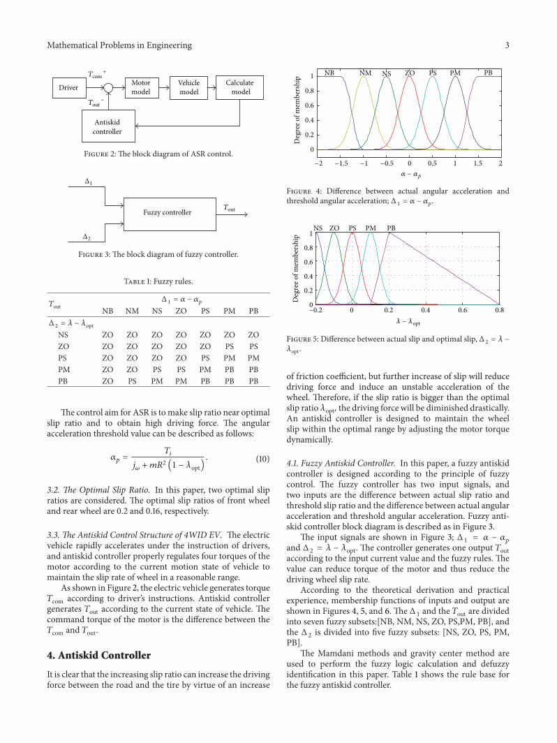
Figure 2: The block diagram of ASR control.
Fuzzy controllerTout
Δ1
Δ2
Figure 3: The block diagram of fuzzy controller.
Table 1: Fuzzy rules.
𝑇outΔ 1 = 𝛼 − 𝛼𝑝
NB NM NS ZO PS PM PBΔ 2 = 𝜆 − 𝜆opt
NS ZO ZO ZO ZO ZO ZO ZOZO ZO ZO ZO ZO ZO PS PSPS ZO ZO ZO ZO PS PM PMPM ZO ZO PS PS PM PB PBPB ZO PS PM PM PB PB PB
The control aim for ASR is tomake slip ratio near optimalslip ratio and to obtain high driving force. The angularacceleration threshold value can be described as follows:
𝛼𝑝 =
𝑇𝑖
𝑗𝜔 + 𝑚𝑅2(1 − 𝜆opt)
. (10)
3.2. The Optimal Slip Ratio. In this paper, two optimal slipratios are considered. The optimal slip ratios of front wheeland rear wheel are 0.2 and 0.16, respectively.
3.3. The Antiskid Control Structure of 4WID EV. The electricvehicle rapidly accelerates under the instruction of drivers,and antiskid controller properly regulates four torques of themotor according to the current motion state of vehicle tomaintain the slip rate of wheel in a reasonable range.
As shown in Figure 2, the electric vehicle generates torque𝑇com according to driver’s instructions. Antiskid controllergenerates 𝑇out according to the current state of vehicle. Thecommand torque of the motor is the difference between the𝑇com and 𝑇out.
4. Antiskid Controller
It is clear that the increasing slip ratio can increase the drivingforce between the road and the tire by virtue of an increase
0 0.5 1 1.5 2
0
0.2
0.4
0.6
0.8
1
Deg
ree o
f mem
bers
hip
NB PM PBNM NS ZO PS
−2 −1.5 −1 −0.5
𝛼 − 𝛼p
Figure 4: Difference between actual angular acceleration andthreshold angular acceleration; Δ 1 = 𝛼 − 𝛼𝑝.
Deg
ree o
f mem
bers
hip
NS ZO PS PM PB
0 0.2 0.4 0.6 0.80
0.2
0.4
0.6
0.8
1
−0.2
𝜆 − 𝜆opt
Figure 5: Difference between actual slip and optimal slip, Δ 2 = 𝜆 −
𝜆opt.
of friction coefficient, but further increase of slip will reducedriving force and induce an unstable acceleration of thewheel. Therefore, if the slip ratio is bigger than the optimalslip ratio 𝜆opt, the driving force will be diminished drastically.An antiskid controller is designed to maintain the wheelslip within the optimal range by adjusting the motor torquedynamically.
4.1. Fuzzy Antiskid Controller. In this paper, a fuzzy antiskidcontroller is designed according to the principle of fuzzycontrol. The fuzzy controller has two input signals, andtwo inputs are the difference between actual slip ratio andthreshold slip ratio and the difference between actual angularacceleration and threshold angular acceleration. Fuzzy anti-skid controller block diagram is described as in Figure 3.
The input signals are shown in Figure 3; Δ 1 = 𝛼 − 𝛼𝑝
and Δ 2 = 𝜆 − 𝜆opt. The controller generates one output 𝑇outaccording to the input current value and the fuzzy rules. Thevalue can reduce torque of the motor and thus reduce thedriving wheel slip rate.
According to the theoretical derivation and practicalexperience, membership functions of inputs and output areshown in Figures 4, 5, and 6. The Δ 1 and the 𝑇out are dividedinto seven fuzzy subsets:[NB, NM, NS, ZO, PS,PM, PB], andthe Δ 2 is divided into five fuzzy subsets: [NS, ZO, PS, PM,PB].
The Mamdani methods and gravity center method areused to perform the fuzzy logic calculation and defuzzyidentification in this paper. Table 1 shows the rule base forthe fuzzy antiskid controller.
4 Mathematical Problems in EngineeringD
egre
e of m
embe
rshi
p NB NM NS ZO PS PM PB
0 200 400 600
0
0.2
0.4
0.6
0.8
1
−600 −400 −200
Tout
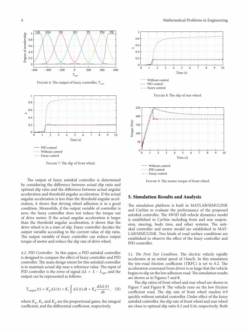
Figure 6: The output of fuzzy controller, 𝑇out.
0 1 2 3 4 5 6 7 8 9 100
0.2
0.4
0.6
0.8
1
Time (s)
Without controlPID control
Fuzzy control
𝜆
Figure 7: The slip of front wheel.
The output of fuzzy antiskid controller is determinedby considering the difference between actual slip ratio andoptimal slip ratio and the difference between actual angularacceleration and threshold angular acceleration. If the actualangular acceleration is less than the threshold angular accel-eration, it shows that driving wheel adhesion is in a goodcondition. Meanwhile, if the output variable of controller iszero, the fuzzy controller does not reduce the torque outof drive motor. If the actual angular acceleration is largerthan the threshold angular acceleration, it shows that thedrive wheel is in a state of slip. Fuzzy controller decides theoutput variable according to the current value of slip ratio.The output variable of fuzzy controller can reduce outputtorque of motor and reduce the slip rate of drive wheel.
4.2. PID Controller. In this paper, a PID antiskid controlleris designed to compare the effect of fuzzy controller and PIDcontroller. The main design intent for this antiskid controlleris to maintain actual slip near a reference value. The input ofPID controller is the error of signal Δ𝜆 = 𝜆 − 𝜆opt, and theoutput can be represented as follows:
𝑇outpid (𝑡) = 𝐾𝑝Δ𝜆 (𝑡) + 𝐾𝑖 ∫Δ𝜆 (𝑡) 𝑑𝑡 + 𝐾𝑑
𝑑Δ𝜆 (𝑡)
𝑑𝑡
, (11)
where𝐾𝑝,𝐾𝑖, and𝐾𝑑 are the proportional gains, the integralcoefficient, and the differential coefficient, respectively.
0 1 2 3 4 5 6 7 8 9 100
0.2
0.4
0.6
0.8
1
Time (s)
Without controlPID controlFuzzy control
𝜆
Figure 8: The slip of rear wheel.
0 1 2 3 4 5 6 7 8 9 100
50
100
150
200
250
Time (s)
Torq
ue (N
m)
Without controlPID controlFuzzy control
Figure 9: The motor torque of front wheel.
5. Simulation Results and Analysis
The simulation platform is built in MATLAB/SIMULINKand CarSim to evaluate the performance of the proposedantiskid controller. The 4WID full-vehicle dynamics modelis established in CarSim including front and rear suspen-sion, steering, body tires, and other systems. The anti-skid controller and motor model are established in MAT-LAB/SIMULINK. Two kinds of road surface conditions areestablished to observe the effect of the fuzzy controller andPID controller.
5.1. The First Test Condition. The electric vehicle rapidlyaccelerates at an initial speed of 5 km/h. In this simulationthe tire-road friction coefficient (TRFC) is set to 0.2. Theacceleration command from driver is so large that the vehiclebegins to slip on the low adhesion road.The simulation resultsare shown as in Figures 7 and 8.
The slip ratios of front wheel and rear wheel are shown inFigure 7 and Figure 8. The vehicle runs on the low frictioncoefficient road. The slip rate of front wheel reaches 0.9quickly without antiskid controller. Under effect of the fuzzyantiskid controller, the slip rate of front wheel and rear wheelare close to optimal slip ratio 0.2 and 0.16, respectively. Both

Mathematical Problems in Engineering 5
Time (s)0 1 2 3 4 5 6 7 8 9 10
0
200
400
600
800
Wheel speed of fuzzy controlWheel speed of without controlVehicle speed
Vx
(km
/h)
Figure 10: Comparison of speed for front wheel.
0 1 2 3 4 5 6 7 8 9 100
10
20
30
40
50
60
Time (s)
PID controlFuzzy control
Without control
𝛼(r
ad/s2)
Figure 11: The actual angular acceleration for front wheel.
of fuzzy controller and PID controllers can reduce the slipand improve the stability of the electric vehicle. However, thecontrol performance of the proposed fuzzy controller is betterthan that of the conventional PID controller.
As shown in Figure 9, both of fuzzy controller and PIDcontroller can reducemotor torque of front wheel. Finally, themotor torques are the same in different control methods. Inaddition, thewheel angular velocity is shown in Figure 10, andthe fuzzy antiskid controller can effectively reduce the wheelangular velocity.
As shown in Figure 11, both of fuzzy controller and PIDcontroller can reduce actual angular acceleration for frontwheel.
As shown in Figure 12, the difference between actualangular acceleration and threshold angular accelerationraises rapidly without antiskid controller. Under the effectof fuzzy antiskid controller, the difference between actualangular acceleration and threshold angular acceleration isclose to zero. The threshold angular acceleration is effectiveto reduce actual angular acceleration.
As shown in Figure 13, The difference between actual slipratio and threshold slip ratio reaches 0.7 rapidly without anti-skid controller. Under the effect of fuzzy antiskid controller,the actual slip ratio is close to optimal slip.
0 1 2 3 4 5 6 7 8 9 10Time (s)
0
10
20
30
40
50
Fuzzy controlWithout control
𝛼−𝛼p
(rad
/s2)
Figure 12: Difference between actual angular acceleration andthreshold angular acceleration.
0 1 2 3 4 5 6 7 8 9 10
0
0.2
0.4
0.6
0.8
Time (s)
Fuzzy controlWithout control
−0.2
𝜆−𝜆
opt
Figure 13:Difference between actual slip ratio and optimal slip ratio.
5.2. The Second Test Condition. The electric vehicle rapidlyaccelerates at an initial speed of 20 km/h. The steering angleof front wheel is 5 degree. In this simulation the TRFC wasset to 0.2. The acceleration command from driver is so largethat the vehicle begins to slip on the low adhesion road. Thesimulation results are shown in Figure 14.
As shown in Figure 14,The slip rate of front wheel reaches0.85 quickly without antiskid controller. Under effect of theantiskid controller, the slip rate of front wheel is close tooptimal slip ratio 0.2.
The lateral acceleration of vehicle is shown in Figure 15.It can be seen from the figure that the lateral acceleration ofvehicle under the effect of antiskid controller is bigger thanthat of lacking antiskid controller before 8 second.The vehiclebegins to spin after 8 second, so the lateral acceleration ofwithout controller is bigger than that of using controller. Boththe fuzzy antiskid controller and PID antiskid controllers canenhance the lateral stability and safety of electric vehicle.
As shown in Figure 16, with the effect of fuzzy antiskidcontroller, the difference between actual angular accelerationand threshold angular acceleration is close to zero. The fuzzy

6 Mathematical Problems in Engineering
Time (s)0 1 2 3 4 5 6 7 8 9 10
0
0.2
0.4
0.6
0.8
1
Without controlFuzzy controlPID control
𝜆
Figure 14: The slip of front wheel.
0 1 2 3 4 5 6 7 8 9 100
0.1
0.2
0.3
0.4
Time (s)
Fuzzy controlPID controlWithout control
a y(m
/s2)
Figure 15: The lateral acceleration of vehicle.
Time (s)0 1 2 3 4 5 6 7 8 9 10
0
10
20
30
40
−10
Without controlFuzzy control
𝛼−𝛼p
(rad
/s2)
Figure 16: Difference between actual angular acceleration andthreshold angular acceleration.
antiskid controller is effective to reduce actual angular accel-eration.
The yaw rate of vehicle is shown in Figure 17. Under theeffect of fuzzy controller, the yaw rate of vehicle maintainssteadiness at 0.018 rad/s while the yaw rate of vehicle withoutfuzzy controller raises quickly. Figure 17 shows that fuzzyantiskid controller can improve lateral stability of electricvehicle to a certain degree on ice road.
0 1 2 3 4 5 6 7 8 9 100
0.0350.0700.1050.1390.1740.2090.2440.279
Time (s)
Fuzzy controlWithout control
𝛾(r
ad/s
)
Figure 17: The yaw rate of vehicle.
6. Conclusions
In the paper, the antiskid fuzzy logic controller for four-wheel independent driving electric vehicles is proposed basedon threshold angular acceleration and optimal slip rate. Thesimulation results show that fuzzy slip rate controller caneffectively reduce the slip ratio. It can enhance the drivingperformance, themaneuverability, and stability of four-wheelindependent driving electric vehicle.
Acknowledgments
This research was supported by the National Science Foun-dation of China (51105074, 51205058) and the Foundation ofState Key Laboratory of Mechanical Transmission (SKLMT-KFKT-201206).
References
[1] L. Keqiang, “Automotive technology development trends andcountermeasures of China,”Automotive Engineering, vol. 31, no.11, pp. 1005–1016, 2009.
[2] G. Chunlin, Z. Zijian, W. Li et al., “Prospects and key factorsanalysis of electric vehicles development,”Automotive Engineer-ing, vol. 34, no. 9, pp. 852–858, 2012.
[3] G. Yin, N. Chen, and P. Li, “Improving handling stabilityperformance of four-wheel steering vehicle via 𝜇-synthesisrobust control,” IEEE Transactions on Vehicular Technology, vol.56, no. 5, pp. 2432–2439, 2007.
[4] Z. Shuai, H. Zhang, J. Wang, J. Li, and M. Ouyang, “CombinedAFS andDYC control of four-wheel-independent-drive electricvehicles over can network with time-varying delays,” IEEETransactions on Vehicular Technology, 2013.
[5] L. Gang, Z. Changfu, Z. Qiang et al., “Acceleration slip regu-lation control of 4WID electric vehicles based on fuzzy roadidentification,” Journal of South China University of Technology,vol. 40, no. 12, pp. 99–104, 2012.
[6] J. Deur, D. Pavkovic, G. Burgio, and D. Hrovat, “A model-basedtraction control strategy non-reliant onwheel slip information,”Vehicle System Dynamics, vol. 49, no. 8, pp. 1245–1265, 2011.
[7] D. Yin, S. Oh, and Y. Hori, “A novel traction control for EVbased on maximum transmissible torque estimation,” IEEETransactions on Industrial Electronics, vol. 56, no. 6, pp. 2086–2094, 2009.

Mathematical Problems in Engineering 7
[8] M. Yoshimura and H. Fujimoto, “Driving torque controlmethod for electric vehicle with in-wheel motors,” IEEJ Trans-actions on Industry Applications, vol. 131, no. 5, pp. 721–728, 2011.
[9] H. Zhang, Y. Shi, and J. Wang, “Observer-based trackingcontroller design for networked predictive control systems withuncertain Markov delays,” International Journal of Control, vol.86, no. 10, pp. 1824–1836, 2013.
[10] R. DeCastro, R. Esteves Araujo, andD. Freitas, “Wheel slip con-trol of EVS based on sliding mode technique with conditionalintegrators,” IEEE Transactions on Industrial Electronics, vol. 60,no. 8, pp. 3256–3271, 2013.
[11] H. Zhang, Y. Shi, and A. Saadat Mehr, “Robust static outputfeedback control and remote PID design for networked motorsystems,” IEEETransactions on Industrial Electronics, vol. 58, no.12, pp. 5396–5405, 2011.
[12] D. Zhiqiang, Fuzzy control of acceleration slip regulation for elec-tric vehicles with in-wheelmotors [M.S. thesis], TongjiUniversity,Shanghai, China, 2006.
[13] H. Zhang, Y. Shi, and M. Liu, “𝐻∞ step tracking control fornetworked discrete-time nonlinear systems with integral andpredictive actions,” IEEE Transactions on Industrial Informatics,vol. 9, no. 1, pp. 337–345, 2013.
[14] Y. Jiantao, Adhesion control method based on nonlinear controlfor four-wheel drive electric vehicle [M.S. thesis], Tongji Univer-sity, Shanghai, China, 2008.
[15] H. Zhang, Y. Shi, and A. Saadat Mehr, “On 𝐻∞ filtering fordiscrete-time takagi-sugeno fuzzy systems,” IEEE Transactionson Fuzzy Systems, vol. 20, no. 2, pp. 396–401, 2012.
[16] N. Zhao and B.-M. Ge, “𝐻∞ robust control of permanentmagnet synchronous motor used in electric vehicle,” ElectricMachines and Control, vol. 11, no. 5, pp. 462–466, 2007.

Submit your manuscripts athttp://www.hindawi.com
Hindawi Publishing Corporationhttp://www.hindawi.com Volume 2014
MathematicsJournal of
Hindawi Publishing Corporationhttp://www.hindawi.com Volume 2014
Mathematical Problems in Engineering
Hindawi Publishing Corporationhttp://www.hindawi.com
Differential EquationsInternational Journal of
Volume 2014
Applied MathematicsJournal of
Hindawi Publishing Corporationhttp://www.hindawi.com Volume 2014
Probability and StatisticsHindawi Publishing Corporationhttp://www.hindawi.com Volume 2014
Journal of
Hindawi Publishing Corporationhttp://www.hindawi.com Volume 2014
Mathematical PhysicsAdvances in
Complex AnalysisJournal of
Hindawi Publishing Corporationhttp://www.hindawi.com Volume 2014
OptimizationJournal of
Hindawi Publishing Corporationhttp://www.hindawi.com Volume 2014
CombinatoricsHindawi Publishing Corporationhttp://www.hindawi.com Volume 2014
International Journal of
Hindawi Publishing Corporationhttp://www.hindawi.com Volume 2014
Operations ResearchAdvances in
Journal of
Hindawi Publishing Corporationhttp://www.hindawi.com Volume 2014
Function Spaces
Abstract and Applied AnalysisHindawi Publishing Corporationhttp://www.hindawi.com Volume 2014
International Journal of Mathematics and Mathematical Sciences
Hindawi Publishing Corporationhttp://www.hindawi.com Volume 2014
The Scientific World JournalHindawi Publishing Corporation http://www.hindawi.com Volume 2014
Hindawi Publishing Corporationhttp://www.hindawi.com Volume 2014
Algebra
Discrete Dynamics in Nature and Society
Hindawi Publishing Corporationhttp://www.hindawi.com Volume 2014
Hindawi Publishing Corporationhttp://www.hindawi.com Volume 2014
Decision SciencesAdvances in
Discrete MathematicsJournal of
Hindawi Publishing Corporationhttp://www.hindawi.com
Volume 2014 Hindawi Publishing Corporationhttp://www.hindawi.com Volume 2014
Stochastic AnalysisInternational Journal of