research article analysis of carbon fiber reinforced peek...
TRANSCRIPT

Research ArticleAnalysis of Carbon Fiber Reinforced PEEK Hinge MechanismArticulation Components in a Rotating Hinge Knee Design:A Comparison of In Vitro and Retrieval Findings
Ronja A. Schierjott,1,2 Alexander Giurea,3 Hans-Joachim Neuhaus,4 Jens Schwiesau,2,5
Andreas M. Pfaff,2 Sandra Utzschneider,5 Gianluca Tozzi,1 and Thomas M. Grupp2,5
1School of Engineering, University of Portsmouth, Portsmouth PO1 3DJ, UK2Aesculap AG, Research & Development, Am Aesculap-Platz, 78532 Tuttlingen, Germany3Department of Orthopaedics, Vienna General Hospital, Medical University of Vienna, Waehringer Guertel 18-20,1090 Vienna, Austria4Department of Traumatology and Orthopaedics, St. Vincenz Hospital, Am Stein 24, 58706 Menden, Germany5Department of Orthopaedic Surgery, Physical Medicine & Rehabilitation, Ludwig Maximilians University Munich,Campus Grosshadern, Marchioninistrasse 15, 81377 Munich, Germany
Correspondence should be addressed to Ronja A. Schierjott; [email protected]
Received 26 August 2016; Revised 5 November 2016; Accepted 15 November 2016
Academic Editor: Konstantinos Anagnostakos
Copyright © 2016 Ronja A. Schierjott et al. This is an open access article distributed under the Creative Commons AttributionLicense, which permits unrestricted use, distribution, and reproduction in any medium, provided the original work is properlycited.
Carbon fiber reinforced poly-ether-ether-ketone (CFR-PEEK) represents a promising alternativematerial for bushings in total kneereplacements, after early clinical failures of polyethylene in this application. The objective of the present study was to evaluate thedamage modes and the extent of damage observed on CFR-PEEK hinge mechanism articulation components after in vivo servicein a rotating hinge knee (RHK) system and to compare the results with corresponding components subjected to in vitro wear tests.Key question was if there were any similarities or differences between in vivo and in vitro damage characteristics. Twelve retrievedRHK systems after an average of 34.9months in vivo underwent wear damage analysis with focus on the four integrated CFR-PEEKcomponents and distinction between different damage modes and classification with a scoring system.The analysis included visualexamination, scanning electron microscopy, and energy dispersive X-ray spectroscopy, as well as surface roughness and profilemeasurements. The main wear damage modes were comparable between retrieved and in vitro specimens (𝑛 = 3), whereby thesize of affected area on the retrieved components showed a higher variation. Overall, the retrieved specimens seemed to be slightlyheavier damaged which was probably attributable to the more complex loading and kinematic conditions in vivo.
1. Introduction
Loosening is considered among themost frequent reasons forknee arthroplasty revision [1–4], together with polyethylene(PE) debris dispersion around the implant area [5, 6].
For knee revisions and primary patients with severe varusor valgus deformities and unstable ligaments, knee arthro-plasty with a rotating hinge knee (RHK) has become a viableclinical treatment [7–11]. However, traditionally applied PEhingemechanism articulation (HMA) components/bushings
may fail, mainly as a consequence of insufficient creep andwear resistance [11–13]. For this reason, different alternativesto PE have been evaluated by Grupp et al. [14, 15]. In thissense, carbon fiber reinforced poly-ether-ether-ketone (CFR-PEEK) represents an attractive alternative bearing materialas it offers high creep and wear resistance and outstandingchemical resistance [16] and has already shown acceptablewear properties in hip and knee articulations [17–19].
The RHK design EnduRo� (Aesculap AG Tuttlingen,Germany) with flanges and bushings made of CFR-PEEK
Hindawi Publishing CorporationBioMed Research InternationalVolume 2016, Article ID 7032830, 12 pageshttp://dx.doi.org/10.1155/2016/7032830

2 BioMed Research International
was clinically introduced in November 2008 and has alreadyshown satisfying results [20].Moreover, the biological activityin vivo of CFR-PEEK debris was reported to be comparableto PE debris [21, 22].
The suitability of CFR-PEEK as knee bearingmaterial hasbeen investigated in vitro on unicondylar knee arthrosplasty[18, 23]. Scholes and Unsworth [18] found that CFR-PEEKperformed well and showed a lower gravimetric wear ratethan conventional metal-UHMWPE (ultra-high-molecular-weight-polyethylene) articulations. However, the results ofGrupp et al. [23] showed no significant wear reductionwith CFR-PEEK compared to UHMWPE in low congruentfixed bearing unicompartmental knee arthroplasty (UKA)articulations and Wang et al. [24] even suggested poorperformance of CFR-PEEK in high-stress nonconformingcontact situations such as in tibial components of a total kneejoint replacement.
Numerous retrieval studies of knee arthroplasties havebeen conducted with focus on the wear of the PE tibial insert[25–27]. In addition, Busanelli et al. reported a case of carbonfiber reinforced PE tibial insert which showed significantlyincreased wear [28]. However, to the authors’ knowledge, nostudy has been published to date on the analysis of retrievedCFR-PEEK knee HMA components.
The main aim of this study is therefore to evaluate thewear damage modes and extent/severity of wear damageobserved on retrieved CFR-PEEK HMA components in therotating hinge knee system EnduRo in comparison withcorresponding in vitro tested specimens. Hence, the keyquestion is if there are any similarities or differences in thewear damage observed on in vivo and in vitro CFR-PEEKHMA components.
2. Materials and Methods
2.1. Implant and Clinical Data. Retrieved and in vitro testedspecimens from the EnduRo rotating hinge knee system(Aesculap AG Tuttlingen, Germany) were used in this study.This mobile bearing design consisted of a multilayer coatedsurface with a ZrN shielding layer (Advanced Surface (AS))or uncoated CoCr
29Mo6femoral and tibial components joint
by a hinged mechanism free to rotate in flexion/extensionand internal/external direction. The bearings of the hingedmechanism were made of CFR-PEEK OPTIMA LT1 CA30(Invibio Ltd, Thornton Cleveleys, UK) consisting of 30%polyacrylonitrile (PAN) fibers and the meniscal bearing wasmade of UHMWPE (machined from GUR 1020), packedunder nitrogen atmosphere, and sterilized using electronbeam irradiation (30 ± 2 kGy) [15].
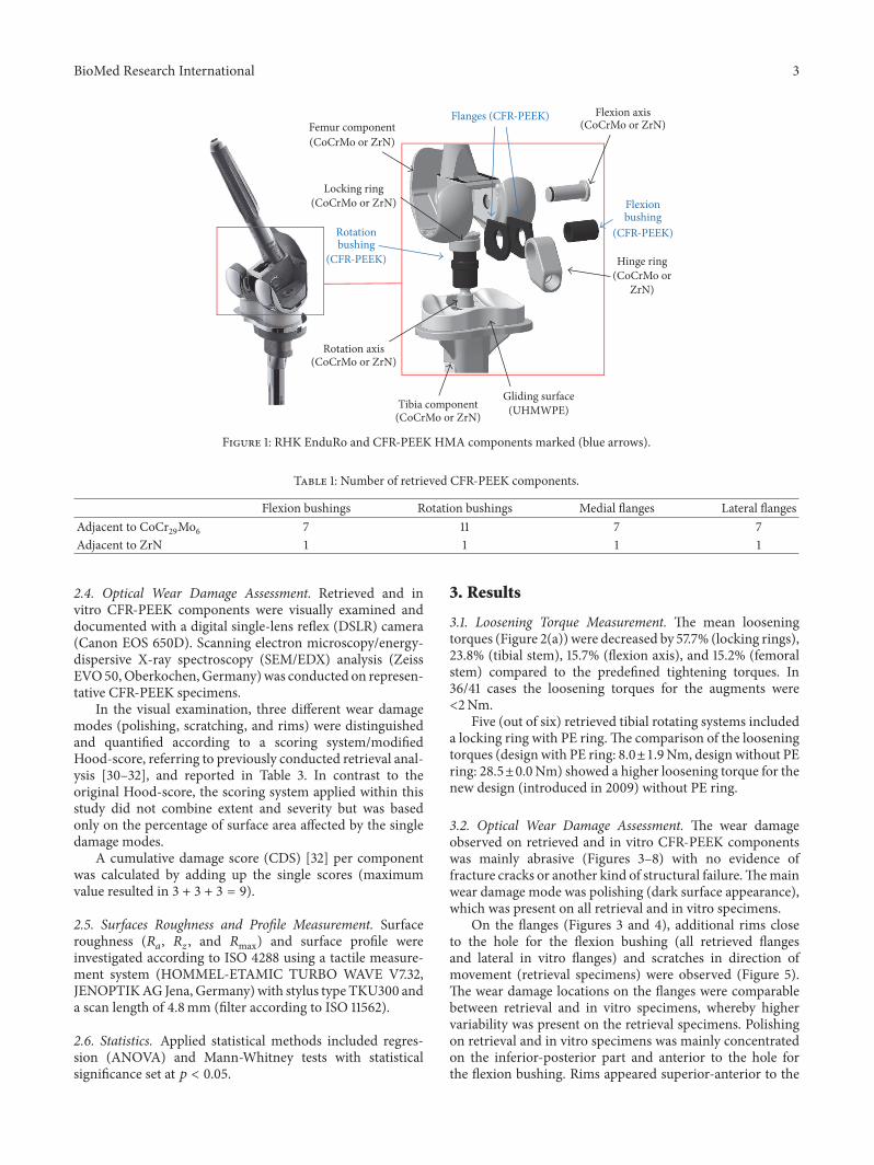
The flexion bushings were articulated with the hinge ringand the flanges (outer surface) and with the flexion axis(inner surface).The rotation bushing contacted the tibial trayand the locking ring (outer surface) and the rotation axis(inner surface).The flanges were articulated with the femoralcomponent and the hinge ring, whereby only the resultsfor the hinge ring side are reported as there is no relativemovement between the flanges and femoral component. Theoverall knee system including the CFR-PEEK components
used in this study is shown in Figure 1. The CFR-PEEKcomponents (Table 1) of 12 revised EnduRo knee systems inall three available implant sizes (Table 2) were analysed.
The average time in vivo (Table 2) was 34.9±18.32monthsfor the rotation bushings and 35.6 ± 22.82 months for theflexion bushings and flanges (in case of retrieval R61 and R63,only the year of implantation was known). Aseptic looseningappeared to be a frequent reason for retrieval (6/12 cases).Thepatient age at implantation was known in 6/12 cases, rangingfrom 54 to 79 (66.7 ± 10.6) and gender distribution was 6/12female, 3/12 male, and 3/12 unknown. For R70, no data wasgiven.
2.2. Comparison with InVitro Tests. Wear damagemodes andcumulative damage scores (CDS) were compared betweenretrieval and CFR-PEEK components tested in vitro (𝑛 = 3each) with ZrN-coated surfaces adjacent to CFR-PEEK [15].The in vitro test with load and movement profiles accordingto ISO 14243-1:2002 (E) was conducted on a customized four-station (3 + 1 reference) load control servohydraulic knee-wear simulator (EndoLab� Mechanical Engineering GmbHThansau/Rosenheim, Germany) to assess the wear behaviorof the EnduRo system under simulation of level walking ofan average person. The knee systems were tested over 5Mio.cycles of 0∘ to 58∘ flexion/extension and 168N to 2600Naxial load with a frequency of 1Hz. Anterior-posterior (AP)motion restraint and internal-external (IE) rotation restraintwere sixfold reduced (5 Nmm−1 and 0.1 Nmdeg−1) comparedto ISO 14243-1:2002 (E) to simulate the absence of cruciateand collateral ligaments in the RHK treatment. Newborncalf serum (Biochrom AG Berlin, Germany) diluted withdeionized water (resulting protein content 30 gL−1) was usedas lubricant and was replaced at intervals of 0.5Mio. cycles.Ethylene diamine tetraacetic acid and patricinewere added tostabilize pH and to prevent fungal degradation. At intervalsof 0.5, 1, 2, 3, 4, and 5Mio. cycles the specimens were cleanedaccording to ISO 14243-2:2002 (E) and the PE gliding surfaceand CFR-PEEK components were analysed gravimetricallyand optically.
Assuming an average of 1.76Mio. cycles/year, 5Mio.cycles equal approximately 2.9 years (34.8 months) in vivo[29].
The loosening torques of the retrieved rotation axissystems were compared to the resulting loosening torquesafter a high demanding activity in vitro test over 1Mio. loadcycles (𝑛 = 4), which was conducted on the EndoLab knee-wear simulator as well.
2.3. Loosening Torque Measurement. The loosening torquesof the femoral and tibial stem, the locking ring for the rotationsystem, and the flexion axis were measured and compared tothe nominal torques predefined for assembly in the surgery.A dial indicating torque wrench with ameasurement range of±50Nm andminimummeasurable torque of 2Nm (TohnichiMfg.Co., Ltd, Tokyo, Japan) was used alongside with specificattachments for each connection (stems, locking ring, andaxis). The torque wrench provided an analogue display witha memory pointer to indicate the torque required to unlooseeach connection.
BioMed Research International 3
Gliding surface(UHMWPE)Tibia component
(CoCrMo or ZrN)
Rotation axis(CoCrMo or ZrN)
Femur component(CoCrMo or ZrN)
Locking ring(CoCrMo or ZrN)
Flexion axis(CoCrMo or ZrN)
Flanges (CFR-PEEK)
Rotationbushing
(CFR-PEEK)
Flexionbushing
(CFR-PEEK)
Hinge ring(CoCrMo or
ZrN)
Figure 1: RHK EnduRo and CFR-PEEK HMA components marked (blue arrows).
Table 1: Number of retrieved CFR-PEEK components.
Flexion bushings Rotation bushings Medial flanges Lateral flangesAdjacent to CoCr
29Mo6
7 11 7 7Adjacent to ZrN 1 1 1 1
2.4. Optical Wear Damage Assessment. Retrieved and invitro CFR-PEEK components were visually examined anddocumented with a digital single-lens reflex (DSLR) camera(Canon EOS 650D). Scanning electron microscopy/energy-dispersive X-ray spectroscopy (SEM/EDX) analysis (ZeissEVO50,Oberkochen,Germany)was conducted on represen-tative CFR-PEEK specimens.
In the visual examination, three different wear damagemodes (polishing, scratching, and rims) were distinguishedand quantified according to a scoring system/modifiedHood-score, referring to previously conducted retrieval anal-ysis [30–32], and reported in Table 3. In contrast to theoriginal Hood-score, the scoring system applied within thisstudy did not combine extent and severity but was basedonly on the percentage of surface area affected by the singledamage modes.
A cumulative damage score (CDS) [32] per componentwas calculated by adding up the single scores (maximumvalue resulted in 3 + 3 + 3 = 9).
2.5. Surfaces Roughness and Profile Measurement. Surfaceroughness (𝑅
𝑎, 𝑅𝑧, and 𝑅max) and surface profile were
investigated according to ISO 4288 using a tactile measure-ment system (HOMMEL-ETAMIC TURBO WAVE V7.32,JENOPTIKAG Jena, Germany) with stylus type TKU300 anda scan length of 4.8mm (filter according to ISO 11562).
2.6. Statistics. Applied statistical methods included regres-sion (ANOVA) and Mann-Whitney tests with statisticalsignificance set at 𝑝 < 0.05.
3. Results
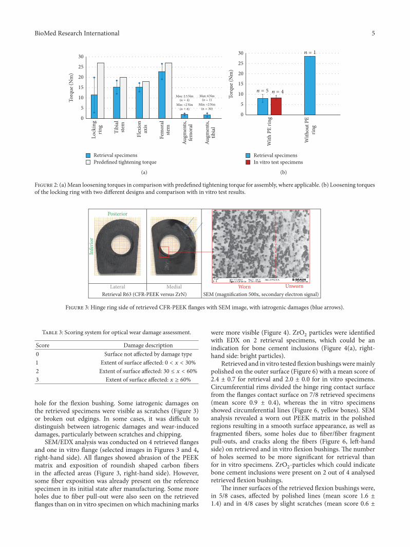
3.1. Loosening Torque Measurement. The mean looseningtorques (Figure 2(a)) were decreased by 57.7% (locking rings),23.8% (tibial stem), 15.7% (flexion axis), and 15.2% (femoralstem) compared to the predefined tightening torques. In36/41 cases the loosening torques for the augments were<2Nm.
Five (out of six) retrieved tibial rotating systems includeda locking ring with PE ring.The comparison of the looseningtorques (design with PE ring: 8.0±1.9Nm, design without PEring: 28.5±0.0Nm) showed a higher loosening torque for thenew design (introduced in 2009) without PE ring.
3.2. Optical Wear Damage Assessment. The wear damageobserved on retrieved and in vitro CFR-PEEK componentswas mainly abrasive (Figures 3–8) with no evidence offracture cracks or another kind of structural failure.Themainwear damage mode was polishing (dark surface appearance),which was present on all retrieval and in vitro specimens.
On the flanges (Figures 3 and 4), additional rims closeto the hole for the flexion bushing (all retrieved flangesand lateral in vitro flanges) and scratches in direction ofmovement (retrieval specimens) were observed (Figure 5).The wear damage locations on the flanges were comparablebetween retrieval and in vitro specimens, whereby highervariability was present on the retrieval specimens. Polishingon retrieval and in vitro specimens was mainly concentratedon the inferior-posterior part and anterior to the hole forthe flexion bushing. Rims appeared superior-anterior to the

4 BioMed Research International
Table2:Overviewof
clinicald
ata,im
planttype,andsiz
efor
retrievedCF
R-PE
EKrotatin
ghingek
neec
ompo
nents.
Specim
enGender
Age
atim
plantatio
n[years]
Treated
side
Implant
type
Implantsize
(glid
ingsurfa
ceheight)
RetrievedCF
R-PE
EKcompo
nents
Timeinvivo
[mon
ths]
Reason
forrevision
R51
F71
Left
CoC
rMo
2(10m
m)
Rotatio
naxisbu
shing
47.0
Infection/sepsis
R52
F76
Right
CoC
rMo
2(14
mm)
Rotatio
naxisbu
shing
12.0
Infection/sepsis
Flexionaxisbu
shing
41.0
Femoralflanges
41.0
R53
F79
Left
CoC
rMo
2(20m
m)
Rotatio
naxisbu
shing
54.0
Aseptic
loosening
Flexionaxisbu
shing
54.0
Femoralflanges
54.0
R54
FUnk
nown
Left
CoC
rMo
2(12m
m)
Rotatio
naxisbu
shing
12.0
Poor
mob
ility,postoperativ
eFlexionaxisbu
shing
12.0
Femoralflanges
12.0
R55
M55
Left
CoC
rMo
3(10m
m)
Rotatio
naxisbu
shing
43.0
Infection/sepsis
R60
F54
Left
CoC
rMo
2(14
mm)
Rotatio
naxisbu
shing
40.5
Aseptic
loosening
Flexionaxisbu
shing
40.5
Femoralflanges
40.5
R61
MUnk
nown
Unk
nown
CoC
rMo
3(12m
m)
Rotatio
naxisbu
shing
55.0
Asepticlooseningandbo
neperfo
ratio
nwith
stem
R63
FUnk
nown
Left
ZrN
2,custo
mized
(12m
m)
Rotatio
naxisbu
shing
60.0
Aseptic
loosening
Flexionaxisbu
shing
60.0
Femoralflanges
60.0
R67
M65
Left
CoC
rMo
3(10m
m)
Rotatio
naxisbu
shing
20.0
Aseptic
loosening
R70
Unk
nown
Unk
nown
Left
CoC
rMo
2(10m
m)
Rotatio
naxisbu
shing
Unk
nown
Unk
nown
Flexionaxisbu
shing
Unk
nown
Femoralflang
esUnk
nown
R71
Unk
nown
Unk
nown
Right
CoC
rMo
1(10mm)
Rotatio
naxisbu
shing
22.0
Aseptic
loosening
Flexionaxisbu
shing
22.0
Femoralflanges
22.0
R72
Unk
nown
Unk
nown
Right
CoC
rMo
3(10m
m)
Rotatio
naxisbu
shing
18.0
Infection/sepsis
Flexionaxisbu
shing
20.0
Femoralflanges
20.0
BioMed Research International 5
0
5
10
15
20
25
30
Tibi
alste
m
Flex
ion
axis
Fem
oral
stem
Augm
ents,
fem
oral
Augm
ents,
tibia
l
Torq
ue (N
m)
Retrieval specimensPredefined tightening torque
Lock
ing
ring
(n = 30)
Min: <2Nm(n = 1)
Max: 6Nm
(n = 6)
Min: <2Nm(n = 4)
Max: 2.5Nm
(a)
0
5
10
15
20
25
30
With
PE
ring
With
out P
Erin
g
Torq
ue (N
m)
Retrieval specimensIn vitro test specimens
n = 4
n = 1
n = 5
(b)
Figure 2: (a)Mean loosening torques in comparison with predefined tightening torque for assembly, where applicable. (b) Loosening torquesof the locking ring with two different designs and comparison with in vitro test results.
SEM (magnification 500x, secondary electron signal)Lateral Medial
Retrieval R63 (CFR-PEEK versus ZrN)
Infe
rior
Worn Unworn
Posterior
Figure 3: Hinge ring side of retrieved CFR-PEEK flanges with SEM image, with iatrogenic damages (blue arrows).
Table 3: Scoring system for optical wear damage assessment.
Score Damage description0 Surface not affected by damage type1 Extent of surface affected: 0 < 𝑥 < 30%2 Extent of surface affected: 30 ≤ 𝑥 < 60%3 Extent of surface affected: 𝑥 ≥ 60%
hole for the flexion bushing. Some iatrogenic damages onthe retrieved specimens were visible as scratches (Figure 3)or broken out edgings. In some cases, it was difficult todistinguish between iatrogenic damages and wear-induceddamages, particularly between scratches and chipping.
SEM/EDX analysis was conducted on 4 retrieved flangesand one in vitro flange (selected images in Figures 3 and 4,right-hand side). All flanges showed abrasion of the PEEKmatrix and exposition of roundish shaped carbon fibersin the affected areas (Figure 3, right-hand side). However,some fiber exposition was already present on the referencespecimen in its initial state after manufacturing. Some moreholes due to fiber pull-out were also seen on the retrievedflanges than on in vitro specimen on whichmachiningmarks
were more visible (Figure 4). ZrO2particles were identified
with EDX on 2 retrieval specimens, which could be anindication for bone cement inclusions (Figure 4(a), right-hand side: bright particles).
Retrieved and in vitro tested flexion bushingsweremainlypolished on the outer surface (Figure 6) with a mean score of2.4 ± 0.7 for retrieval and 2.0 ± 0.0 for in vitro specimens.Circumferential rims divided the hinge ring contact surfacefrom the flanges contact surface on 7/8 retrieved specimens(mean score 0.9 ± 0.4), whereas the in vitro specimensshowed circumferential lines (Figure 6, yellow boxes). SEManalysis revealed a worn out PEEK matrix in the polishedregions resulting in a smooth surface appearance, as well asfragmented fibers, some holes due to fiber/fiber fragmentpull-outs, and cracks along the fibers (Figure 6, left-handside) on retrieved and in vitro flexion bushings. The numberof holes seemed to be more significant for retrieval thanfor in vitro specimens. ZrO
2-particles which could indicate
bone cement inclusions were present on 2 out of 4 analysedretrieved flexion bushings.
The inner surfaces of the retrieved flexion bushings were,in 5/8 cases, affected by polished lines (mean score 1.6 ±1.4) and in 4/8 cases by slight scratches (mean score 0.6 ±

6 BioMed Research International
Lateral Medial
(a)
Lateral Medial
(b) In vitro 1 (CFR-PEEK versus ZrN)
Infe
rior
Infe
rior
SEM (magnification 500x, backscattered electron signal)Retrieval R53 (CFR-PEEK versus CoCrMo)
Posterior
Posterior
Figure 4: Hinge ring side of CFR-PEEK femoral flanges with SEM images. (a) Retrieved flanges adjacent to CoCrMo and (b) in vitro testedflanges adjacent to ZrN. Holes due to fiber pull-out (yellow arrows) and machining marks (green arrows) are shown.
0.0
0.5
1.0
1.5
2.0
2.5
3.0
Polishing Scratching Rims
Dam
age s
core
Damage mode
Retrieved flangesIn vitro test flanges
∗∗
Figure 5:Wear damage modes on retrieved and in vitro wear testedflanges. ∗Standard deviation = 0 for equal values on all analysedspecimens.
0.7) in circumferential direction, whereas the correspondingsurfaces of the in vitro specimens showed an overall polishedappearance (Figure 7).
The outer surface of the retrieved and in vitro rotationbushings was polished (mean score 1.7 ± 0.7 for retrieval and1.0 ± 0.0 for in vitro specimens) on the edgings (Figure 8(b),red boxes). On the inner surface of all rotating bushings,polished circumferential lines (red arrows) could be observed(mean score 1.0 ± 0.7 for retrieval and 1.3 ± 0.6 for in vitrospecimens) (Figure 8(a)).
3.3. Cumulative Damage Score. Mean cumulative wear dam-age scores were higher for the retrieval than for the in vitrospecimens, except for the axis contact surfaces of flexion androtation bushings (Figure 9). The trend in linear regressionof CDS and time in vivo was found for the hinge ring/flangescontact surface of flexion bushings (𝑅2 = 0.8003 and 𝑝 =0.0123).
3.4. Surfaces Roughness and Profile Measurement. The pol-ishing in the worn areas was confirmed by reduced averageroughness (𝑅
𝑎) values in comparisonwith themanufacturing
roughness (Figure 10(a)). The overall polished appearanceon the inner surface of the in vitro flexion bushings wasconfirmed by the 𝑅
𝑎values, more significantly decreased

BioMed Research International 7
Retrieval R63 (CFR-PEEK versus ZrN)
Hinge ring contact area
Flange contact area
(a)
Retrieval R54 (CFR-PEEK versus CoCrMo)
(b)
In vitro 1 (CFR-PEEK versus ZrN)
(c)
Figure 6: ((a) and (b)) Hinge ring/flanges contact area of retrieved flexion bushings. (c) Corresponding contact area on in vitro specimen 1.Images: DSLR camera and SEM with magnification 100x (right-hand side) and 500x (left-hand side). Holes due to fiber pull-out are markedwith yellow arrows.
than for the retrieval specimens. No statistically significantcorrelation of decreased roughness values and time in vivowas found (𝑝 > 0.05 in all cases).The surface profilemeasure-ment revealed rims on 7/8 retrieved flexion bushings (hingering/flanges contact surface), whereas the in vitro specimensshowed an elevation at the same location (Figure 10(b)).Linear regression of rimdepth and time in vivowas calculatedand a poor correlationwas found for the flanges (𝑅2 = 0.4253,𝑝 = 0.0496).
4. Discussion
The main objective of the present study was to evaluate thewear damage modes and the extent of damage observed onCFR-PEEK HMA components in articulation with CoCrMoand ZrN multilayer surfaces after service in vivo in aRHK system and then compare the results with those from
implant components subjected to in vitro wear testing. Keyquestion of the study was if there existed any similaritiesor differences in the wear damage observed in vivo andin vitro. Retrieval and in vitro specimens showed commondamage characteristics but also some differences which areboth discussed in detail within the following paragraph.To the authors’ knowledge, this is the first study reportingretrieval analysis of CFR-PEEKHMAcomponents in rotatinghinge type knee endoprostheses. No failure of retrieved CFR-PEEK HMA components occurred in the current study, incontrast to previously reported cases of mechanical failure ofPE bushings within five months after implantation [12, 13].
4.1. Similarities. The observed wear damage on CFR-PEEKretrieval and in vitro specimens was mainly abrasive withpolishing as main damage mode. In some cases, there wasan emerging difficulty to distinguish between wear-induced

8 BioMed Research International
Retrieval R63 (CFR-PEEK versus ZrN)
Retrieval R54(CFR-PEEK versus CoCrMo)
In vitro 1(CFR-PEEK versus ZrN)
Polished lines Overall polished surface
Scratches
Circumferential scratches/grooves
Figure 7: Contact surface of flexion bushings with flexion axis.
Distal
Proximal
(a)
Retrieval R63(CFR-PEEK versus ZrN)
Retrieval R54(CFR-PEEK versus CoCrMo)
Retrieval R55(CFR -PEEK versus CoCrMo)
In vitro 1(CFR-PEEK versus ZrN)
Proximal
Distal5mm 5mm 5mm 5mm
(b)
Figure 8: (a) Contact surface of rotation bushings with rotation axis (proximal view). (b) Contact surface of rotation bushings with tibialtray and locking ring.
and iatrogenic damages due to revision surgery, as alreadyreported by Kurtz et al. [33]. The reduced average roughnessin worn areas found in this study has been already docu-mented for a retrieved CFR-PEEK acetabular liner adjacentto an alumina head [34] and for CFR-PEEK acetabular cupstested within a simulator study [17].
At microscopic level, the PEEK matrix was worn out andfibers were exposed, which has been previously observed onCFR-PEEK unicondylar gliding surfaces [23]. In addition,the currently analysed CFR-PEEK retrieval and the in vitrospecimens showed some fragmented fibers and fiber/fiber
fragment pull-outs, as well as some cracks along fibers inthe worn areas that appeared smooth compared to regions ininitial state.
4.2. Differences. Discrepancies between retrieval and in vitrospecimens included circumferential rims on the retrievedflexion bushings, additional scratches in the direction ofmovement on the retrieved flanges, and the absence of rimson the medial in vitro flanges. The rims on the retrievedflexion bushings could be related to an increased relativemovement of flexion bushings and hinge rings, maybe

BioMed Research International 9
0.01.02.03.04.05.06.07.08.09.0
Flex
ion
bush
ings
,hi
nge r
ing/
flang
essu
rface
Flex
ion
bush
ings
,fle
xion
axis
surfa
ce
Flan
ges,
hing
e rin
g su
rface
Rota
tion
bush
ings
,tib
ial p
late
au/
lock
ing
ring
surfa
ce
Rota
tion
bush
ings
,ro
tatio
n ax
is su
rface
Mea
n cu
mul
ativ
e dam
age s
core
Retrieval specimens (CFR-PEEK versus CoCrMo and ZrN)In vitro test specimens (CFR-PEEK versus ZrN)
p = 0.018p > 0.05
p > 0.05
p > 0.05p > 0.05
∗
∗
∗
Figure 9: Mean cumulative damage score separated according tocomponent type and origin. ∗Standard deviation = 0 for equal valueson all analysed specimens.
due to patient-related inconsistencies such as varus-valguspositioning and corresponding tilting movement, as well asmuscular/soft tissue insufficiencies. Additional scratches onretrieved flanges might be due to potential bone/cementdebris.
Mann-Whitney tests revealed significantly lower 𝑅𝑎val-
ues on the outer surface of the retrieved flexion bushingsand significantly higher 𝑅
𝑎values on their inner surface
(in comparison with in vitro bushings). This indicated thatthe main flexion-extension movement appeared between theflexion bushing and the hinge ring (in vivo) and the bushingand the flexion axis, respectively (in vitro). This may beattributable to different activities in vivo and in vitro, aswell as different movement amplitudes and frequencies, thatis, varying velocity during standing up and a large numberof small movements not making use of the whole range ofmovement available in vivo.
The cumulative wear damage scores within the presentstudy were higher for the retrieval than for the in vitrospecimens (except inner surface of rotation and flexion bush-ings). Harman et al. [35] also found that wear simulationsunderestimated the size of damage pattern and variety ofdamagemodes in vivo for unicondylar tibial inserts.The sameauthor reported underestimation of magnitude of damagearea and extent for retrieved tibial inserts [36], a findingwhich is also supported by the results of Rawlinson et al.[37]. Furthermore, a higher variation of damaged areas (sizeof affected surface area and cumulative damage score, resp.)for retrieval than for in vitro specimens was observed. Thiswas also found by Harman et al. who showed a considerablyhigher variation of damaged areas within retrieval specimensof 27 to 81% [36] and more dispersed damage patternon retrieval than on in vitro specimens [35]. A trend forcorrelation of cumulative damage score and time in vivo wasonly found for the outer surface of flexion bushings with
𝑅2 = 0.8003 and 𝑝 = 0.0123, whereby the absence of astrong correlation of damage size and service time in vivo wasalready reported for UHMWPE unicondylar gliding surfaces[35].
ZrO2particles related to bone cement fragments were
documented with EDX on 4 retrieved components, but noton the in vitro specimens.This is consistent with the findingsof Harman et al. [35] who observed abrasive wear withbone and/or cement on 7/17 (41%) retrieved UHMWPEunicondylar tibial inserts but not on in vitro specimens.
4.3. General View. It is assumed that unknown parameterssuch as body weight [38, 39], activity level [40], type ofactivity other than walking [41, 42], variations in componentalignment and soft tissue restraint [43, 44], and surgicaltechnique [45] may affect the loading conditions and hencethe wear damage characteristics even more than the servicetime in vivo. In particular, the activity levels in patients withjoint replacements were found to be highly variable [40]and greater than generally thought [46]. As in vitro kneejoint wear simulations aim to reproduce the wear damageoccurring in an optimally aligned, well-functioning artificialjoint [36] it is reasonable that some discrepancies betweenretrieved and in vitro specimens appeared in the presentstudy.
The increased loosening torque of the retrieved lockingring without PE ring (𝑛 = 1) underlined the efficacy of thenew implant design.
A limitation of the present study may arise in the smallnumber of samples, in particular of in vitro specimens (𝑛 = 3)and retrieval specimens in articulation with ZrN multilayersurface (𝑛 = 1), which restricted the validity of the statisticalanalysis.The small sample size typical of knee-wear simulatorstudies was previously pointed out by Harman et al. [36].However, it is assumed that the methods applied withinthis preliminary study can show a statistical trend. Tactileroughnessmeasurementwas restricted to a linemeasurementof length 4.8mm and depicted a spot test within the wornareas.
5. Conclusion
The main wear damage modes were comparable betweenretrieval and in vitro specimens, whereby the size of affectedarea on the retrieved components showed a higher varia-tion. Overall, the retrieved specimens seemed to be slightlyheavier worn, although the in vitro applied cycle numberwas comparable to the mean service time of the retrievalspecimens. This is probably attributable to the more complexloading conditions in vivo and the fact that simulationstudies aim to reproduce the wear damage which occursin an optimally aligned knee prosthesis without taking intoaccount patient and surgery specific variances from the ideal.Future work should include additional in vitro testing inorder to enlarge the statistical power and comparisons within vitro tests simulating high demanding activities includingstair climbing, hiking, and deep squatting [29]. Wear damagerelated volume loss and material morphology should beassessed by means of microCT and optical interferometry for

10 BioMed Research International
0.000.200.400.600.801.001.201.401.601.80
Flex
ion
bush
ings
,hi
nge r
ing/
flang
es su
rface
Flex
ion
bush
ings
,fle
xion
axis
surfa
ce
Flan
ges,
hing
e rin
g su
rface
Rota
tion
bush
ings
,tib
ial p
late
au/
lock
ing
ring
surfa
ce
Rota
tion
bush
ings
,ro
tatio
n ax
issu
rface
Retrieval specimens (CFR-PEEK versus CoCrMo and ZrN)In vitro test specimens (CFR-PEEK versus ZrN)Manufacturing roughness
p > 0.05p > 0.05 p = 0.029
p = 0.012
p = 0.012
Ra
(𝜇m
)
(a)
Retrieval specimens (CFR-PEEK versus CoCrMoand ZrN)In vitro test specimens (CFR-PEEK versus ZrN)
0.0000.0050.010
Surfa
ce p
rofil
e cha
nge (
mm
) Flexion bushings Flanges
−0.005
−0.010
−0.015
−0.020
−0.025
−0.030
p = 0.017 p > 0.05
(b)
Figure 10: (a) Average roughness (𝑅𝑎) values of the retrieved flexion bushings, flanges, and rotation bushings in comparison with in vitro
test specimens and the nominal average roughness. (b) Surface profile variations on flexion bushings and flanges.
further quantification of the surface damage and to obtaininformation about any potential damages within thematerial.
Ethical Approval
This study was approved by the Ludwig Maximilians Univer-sity Munich ethics committee (ethics vote reference number39-15).
Competing Interests
Four of the authors (R. A. Schierjott, J. Schwiesau, A.M. Pfaff,and T. M. Grupp) are employees of Aesculap AG Tuttlingen,a manufacturer of orthopaedic implants. One of the authors(S. Utzschneider) is getting institutional research funding foranalysis of tissue. One of the authors (A. Giurea) is advisingsurgeon in Aesculap R&D projects.
Acknowledgments
The authors would like to thank PD Dr. Thielemann(Schwarzwald-Baar Clinics, Villingen-Schwenningen, Ger-many) and Dr. Sweeney (Hospital Bethesda Freudenberg,Germany) for the provision of retrieval specimens, EndoLabGmbH (Thansau/Rosenheim, Germany) for the performanceof the in vitro test, Andreas Fritz for the performance ofsurface analysis, and Mara Catalina Aguilera Canon for herwork on part of the SEM/EDX analysis.
References
[1] O. Robertsson, K. Knutson, S. Lewold, and L. Lidgren, “TheSwedish Knee Arthroplasty Register 1975-1997: an update with
special emphasis on 41,223 knees operated on in 1988–1997,”Acta Orthopaedica Scandinavica, vol. 72, no. 5, pp. 503–513,2001.
[2] Y. Kasahara, T. Majima, S. Kimura, O. Nishiike, and J. Uchida,“What are the causes of revision total knee arthroplasty inJapan?”Clinical Orthopaedics and Related Research, vol. 471, no.5, pp. 1533–1538, 2013.
[3] P. F. Sharkey, P. M. Lichstein, C. Shen, A. T. Tokarski, and J.Parvizi, “Why are total knee arthroplasties failing today-hasanything changed after 10 years?” The Journal of Arthroplasty,vol. 29, no. 9, pp. 1774–1778, 2014.
[4] P. Sadoghi, M. Liebensteiner, M. Agreiter, A. Leithner, N.Bohler, and G. Labek, “Revision surgery after total jointarthroplasty: a complication-based analysis using worldwidearthroplasty registers,” Journal of Arthroplasty, vol. 28, no. 8, pp.1329–1332, 2013.
[5] P. E. Purdue, P. Koulouvaris, H. G. Potter, B. J. Nestor, and T.P. Sculco, “The cellular and molecular biology of periprostheticosteolysis,” Clinical Orthopaedics and Related Research, no. 454,pp. 251–261, 2007.
[6] P. A. Revell, “The combined role of wear particles, macrophagesand lymphocytes in the loosening of total joint prostheses,”Journal of the Royal Society Interface, vol. 5, no. 28, pp. 1263–1278, 2008.
[7] F. Hossain, S. Patel, and F. S. Haddad, “Midterm assessment ofcauses and results of revision total knee arthroplasty,” ClinicalOrthopaedics and Related Research, vol. 468, no. 5, pp. 1221–1228, 2010.
[8] R. L. Barrack, “Evolution of the rotating hinge for complex totalknee arthroplasty,” Clinical Orthopaedics and Related Research,no. 392, pp. 292–299, 2001.
[9] N. Joshi and A. Navarro-Quilis, “Is there a place for rotating-hinge arthroplasty in knee revision surgery for aseptic loosen-ing?” Journal of Arthroplasty, vol. 23, no. 8, pp. 1204–1211, 2008.

BioMed Research International 11
[10] D. J. Deehan, J. Murray, P. D. Birdsall, J. P. Holland, and I. M.Pinder, “The role of the rotating hinge prosthesis in the salvagearthroplasty setting,” Journal of Arthroplasty, vol. 23, no. 5, pp.683–688, 2008.
[11] D. Pacha-Vicente, A. Malik, E. Castellet-Feliu, and J. Nardi-Vilardaga, “Dislocation of rotating-hinge knee prostheses withantidislocationmechanism,”The Journal of Arthroplasty, vol. 23,no. 2, pp. 299–303, 2008.
[12] J. K. L. Lee, V. Chatrath, and P. R. Kim, “Repeated early failure ofa newly designed hinged knee system,” Journal of Arthroplasty,vol. 28, no. 2, pp. 375.e17–375.e21, 2013.
[13] C.-J. Wang and H. E. Wang, “Early catastrophic failure ofrotating hinge total knee prosthesis,” Journal of Arthroplasty,vol. 15, no. 3, pp. 387–391, 2000.
[14] T.M.Grupp,H.-J.Meisel, J. A. Cotton et al., “Alternative bearingmaterials for intervertebral disc arthroplasty,” Biomaterials, vol.31, no. 3, pp. 523–531, 2010.
[15] T. M. Grupp, A. Giurea, R. K. Miehlke et al., “Biotribology ofa new bearing material combination in a rotating hinge kneearticulation,” Acta Biomaterialia, vol. 9, no. 6, pp. 7054–7063,2013.
[16] S. M. Kurtz and J. N. Devine, “PEEK biomaterials in trauma,orthopedic, and spinal implants,” Biomaterials, vol. 28, no. 32,pp. 4845–4869, 2007.
[17] S. C. Scholes, I. A. Inman, A.Unsworth, and E. Jones, “Tribolog-ical assessment of a flexible carbon-fibre-reinforced poly(ether-ether-ketone) acetabular cup articulating against an aluminafemoral head,” Proceedings of the Institution of MechanicalEngineers, Part H: Journal of Engineering in Medicine, vol. 222,no. 3, pp. 273–283, 2008.
[18] S. C. Scholes and A. Unsworth, “Pitch-based carbon-fibre-reinforced poly (ether-ether-ketone) OPTIMA� assessed as abearing material in a mobile bearing unicondylar knee joint,”Proceedings of the Institution of Mechanical Engineers, Part H:Journal of Engineering in Medicine, vol. 223, no. 1, pp. 13–25,2009.
[19] S. C. Scholes and A. Unsworth, “The tribological performanceof a CFR-PEEK-OPTIMA mobile bearing unicondylar kneejoint,” Orthopaedic Proceedings, vol. 92, p. 156, 2010.
[20] A. Giurea, H.-J. Neuhaus, R. Miehlke et al., “Early results ofa new rotating hinge knee implant,” BioMed Research Interna-tional, vol. 2014, Article ID 948520, 8 pages, 2014.
[21] S. Utzschneider, F. Becker, T. M. Grupp et al., “Inflammatoryresponse against different carbon fiber-reinforced PEEK wearparticles compared with UHMWPE in vivo,” Acta Biomateri-alia, vol. 6, no. 11, pp. 4296–4304, 2010.
[22] V. Lorber, A. C. Paulus, A. Buschmann et al., “Elevatedcytokine expression of different PEEK wear particles comparedto UHMWPE in vivo,” Journal of Materials Science: Materials inMedicine, vol. 25, no. 1, pp. 141–149, 2014.
[23] T. M. Grupp, S. Utzschneider, C. Schroder et al., “Biotribologyof alternative bearing materials for unicompartmental kneearthroplasty,” Acta Biomaterialia, vol. 6, no. 9, pp. 3601–3610,2010.
[24] A. Wang, R. Lin, C. Stark, and J. H. Dumbleton, “Suitabilityand limitations of carbon fiber reinforced PEEK composites asbearing surfaces for total joint replacements,” Wear, vol. 225-229, no. II, pp. 724–727, 1999.
[25] T. J. Heyse, J. Davis, S. B. Haas, D. X. Chen, T. M.Wright, and R.S. Laskin, “Retrieval analysis of femoral zirconium componentsin total knee arthroplasty: preliminary results,” The Journal ofArthroplasty, vol. 26, no. 3, pp. 445–450, 2011.
[26] K. Bali, D. D. Naudie, J. L. Howard, R. W. McCalden, S. J.MacDonald, and M. G. Teeter, “Comparison of tibial insertpolyethylene damage in rotating hinge and highly constrainedtotal knee arthroplasty: a retrieval analysis,” Journal of Arthro-plasty, vol. 31, no. 1, pp. 290–294, 2016.
[27] E. A. Schnaser, M. E. Elpers, C. N. Koch, S. B. Haas, G. H.Westrich, and T. M. Wright, “Posterior stabilized polyethyleneinserts in total knee arthroplasty: a retrieval study comparingconventional to high-flexion designs,” Journal of Arthroplasty,vol. 31, no. 2, pp. 495–500, 2016.
[28] L. Busanelli, S. Squarzoni, L. Brizio, D. Tigani, and A. Sudanese,“Wear in carbon fiber-reinforced polyethylene (poly-two) kneeprostheses,” La Chirurgia degli Organi di Movimento, vol. 81, no.3, pp. 263–267, 1996.
[29] J. Schwiesau, C. Schilling, C. Kaddick et al., “Definition andevaluation of testing scenarios for knee wear simulation underconditions of highly demanding daily activities,”Medical Engi-neering and Physics, vol. 35, no. 5, pp. 591–600, 2013.
[30] H. S. Hothi, R. Berber, R. K. Whittaker, P. J. Bills, J. A. Skinner,and A. J. Hart, “Detailed inspection of metal implants,” HIPInternational, vol. 25, no. 3, pp. 227–231, 2015.
[31] R. W. Hood, T. M. Wright, and A. H. Burstein, “Retrievalanalysis of total knee prostheses: a method and its applicationto 48 total condylar prostheses,” Journal of Biomedical MaterialsResearch, vol. 17, no. 5, pp. 829–842, 1983.
[32] T. T. Manson, N. H. Kelly, J. D. Lipman, T. M. Wright, and G.H. Westrich, “Unicondylar knee retrieval analysis,” Journal ofArthroplasty, vol. 25, no. 6, pp. 108–111, 2010.
[33] S. M. Kurtz, T. H. Lanman, G. Higgs et al., “Retrieval analysisof PEEK rods for posterior fusion and motion preservation,”European Spine Journal, vol. 22, no. 12, pp. 2752–2759, 2013.
[34] N. Pace, M. Marinelli, and S. Spurio, “Technical and HistologicAnalysis of a Retrieved Carbon Fiber-Reinforced Poly-Ether-Ether-Ketone Composite Alumina-Bearing Liner 28 MonthsAfter Implantation,” Journal of Arthroplasty, vol. 23, no. 1, pp.151–155, 2008.
[35] M. Harman, S. Affatato, M. Spinelli, M. Zavalloni, S. Stea,and A. Toni, “Polyethylene insert damage in unicondylarknee replacement: a comparison of in vivo function and invitro simulation,” Proceedings of the Institution of MechanicalEngineers Part H: Journal of Engineering in Medicine, vol. 224,no. 7, pp. 823–830, 2010.
[36] M. K. Harman, J. Desjardins, L. Benson, S. A. Banks, M.Laberge, and W. A. Hodge, “Comparison of polyethylenetibial insert damage from in vivo Function and in vitro wearsimulation,” Journal of Orthopaedic Research, vol. 27, no. 4, pp.540–548, 2009.
[37] J. J. Rawlinson, B. D. Furman, S. Li, T. M. Wright, and D. L.Bartel, “Retrieval, experimental, and computational assessmentof the performance of total knee replacements,” Journal ofOrthopaedic Research, vol. 24, no. 7, pp. 1384–1394, 2006.
[38] G. Bergmann, A. Bender, F. Graichen et al., “Standardized loadsacting in knee implants,” PLoS ONE, vol. 9, no. 1, Article IDe86035, 2014.
[39] S. Battaglia, P. Taddei, S. Tozzi, A. Sudanese, and S. Affatato,“Toward the interpretation of the combined effect of size andbody weight on the tribological performance of total kneeprostheses,” International Orthopaedics, vol. 38, no. 6, pp. 1183–1190, 2014.
[40] C. J. Lavernia, R. J. Sierra, D. S. Hungerford, and K. Krackow,“Activity level and wear in total knee arthroplasty: a study of

12 BioMed Research International
autopsy retrieved specimens,” Journal of Arthroplasty, vol. 16,no. 4, pp. 446–453, 2001.
[41] J. M. Weiss, P. C. Noble, M. A. Conditt et al., “What functionalactivities are important to patients with knee replacements?”Clinical Orthopaedics and Related Research, vol. 404, pp. 172–188, 2002.
[42] J. Schwiesau, B. Fritz, I. Kutzner, G. Bergmann, andT.M.Grupp,“CR TKA UHMWPE wear tested after artificial aging of thevitamin E treated gliding component by simulating daily patientactivities,” BioMed Research International, vol. 2014, Article ID567374, 9 pages, 2014.
[43] J. D. DesJardins, S. A. Banks, L. C. Benson, T. Pace, and M.LaBerge, “A direct comparison of patient and force-controlledsimulator total knee replacement kinematics,” Journal of Biome-chanics, vol. 40, no. 15, pp. 3458–3466, 2007.
[44] T. M. McGloughlin and A. G. Kavanagh, “Wear of ultra-highmolecular weight polyethylene (UHMWPE) in total knee pros-theses: a review of key influences,” Proceedings of the Institutionof Mechanical Engineers, Part H: Journal of Engineering inMedicine, vol. 214, no. 4, pp. 349–359, 2000.
[45] P. S. Walker, P. A. Meere, and C. P. Bell, “Effects of surgicalvariables in balancing of total knee replacements using aninstrumented tibial trial,” Knee, vol. 21, no. 1, pp. 156–161, 2014.
[46] A. A. J. Goldsmith, D. Dowson, B. M. Wroblewski et al.,“Comparative study of the activity of total hip arthroplastypatients and normal subjects,” The Journal of Arthroplasty, vol.16, no. 5, pp. 613–619, 2001.

Submit your manuscripts athttp://www.hindawi.com
ScientificaHindawi Publishing Corporationhttp://www.hindawi.com Volume 2014
CorrosionInternational Journal of
Hindawi Publishing Corporationhttp://www.hindawi.com Volume 2014
Polymer ScienceInternational Journal of
Hindawi Publishing Corporationhttp://www.hindawi.com Volume 2014
Hindawi Publishing Corporationhttp://www.hindawi.com Volume 2014
CeramicsJournal of
Hindawi Publishing Corporationhttp://www.hindawi.com Volume 2014
CompositesJournal of
NanoparticlesJournal of
Hindawi Publishing Corporationhttp://www.hindawi.com Volume 2014
Hindawi Publishing Corporationhttp://www.hindawi.com Volume 2014
International Journal of
Biomaterials
Hindawi Publishing Corporationhttp://www.hindawi.com Volume 2014
NanoscienceJournal of
TextilesHindawi Publishing Corporation http://www.hindawi.com Volume 2014
Journal of
NanotechnologyHindawi Publishing Corporationhttp://www.hindawi.com Volume 2014
Journal of
CrystallographyJournal of
Hindawi Publishing Corporationhttp://www.hindawi.com Volume 2014
The Scientific World JournalHindawi Publishing Corporation http://www.hindawi.com Volume 2014
Hindawi Publishing Corporationhttp://www.hindawi.com Volume 2014
CoatingsJournal of
Advances in
Materials Science and EngineeringHindawi Publishing Corporationhttp://www.hindawi.com Volume 2014
Smart Materials Research
Hindawi Publishing Corporationhttp://www.hindawi.com Volume 2014
Hindawi Publishing Corporationhttp://www.hindawi.com Volume 2014
MetallurgyJournal of
Hindawi Publishing Corporationhttp://www.hindawi.com Volume 2014
BioMed Research International
MaterialsJournal of
Hindawi Publishing Corporationhttp://www.hindawi.com Volume 2014
Nano
materials
Hindawi Publishing Corporationhttp://www.hindawi.com Volume 2014
Journal ofNanomaterials