report resumes - eric · report resumes. ed 021 102. vt 005 685 automotive diesel. maintenance 2....
TRANSCRIPT

REPORT RESUMESED 021 102 VT 005 685AUTOMOTIVE DIESEL. MAINTENANCE 2. UNIT I, UNDERSTANDINGMECHANICAL CLUTCHES.
HUMAN ENGINEERING INSTITUTE, CLEVELAND, OHIOREPORT NUMBER AM-2-1 PUB DATE 7 DEC 68MINNESOTA STATE DEFT. OF EDUCATION, ST. PAULEDRS PRICE MF-$0.25 HC-$1.92 46P.
DESCRIPTORS- *STUDY GUIDES, *TEACHING GUIDES, *TRADE ANDINDUSTRIAL EDUCATION, *AUTO MECHANICS (OCCUPATION), DIESELENGINES, *EQUIPMENT MAINTENANCE, KINETICS, MOTOR VEHICLES,ADULT VOCATIONAL EDUCATION, TRANSPARENCIES, PROGRAMEDMATERIALS, INDIVIDUAL INSTRUCTION, INSTRUCTIONAL FILMS,PROGRAMED INSTRUCTION,
ONE OF A 25-MODULE COURSE DESIGNED TO UPGRADE THE JOBSKILLS AND TECHNICAL KNOWLEDGE OF DIESEL MAINENANCE MECHANICSTHIS MATERIAL WAS DEVELOPED BY INDUSTRIAL TRAINING ANDSUBJECT-MATTER SPECIALISTS AND TESTED IN INDUSTRIAL TRAININGSITUATIONS. THE PURPOSE OF THIS FIRST UNIT IS TO DEVELOP ANUNDERSTANDING OF COMPONENTS, OPERATION, AND ADJUSTMENTS OFTHE DIFFERENT TYPES OF MECHANICAL CLUTCHES USED ON DIESELPOWERED VEHICLES. THE MODULE CONSISTS OF AN INSTRUCTOR'SGUIDE, TRANSPARENCIES, AND A LIST OF SUGGESTED SUPPLEMENTARYMATERIALS FOR 2 HOURS OF GROUP INSTRUCTION, TRAINEE TEXTMATERIAL, AND A SELF-INSTRUCTIONAL BRANCH PROGRAMED TRAININGFILM "LEARNING ABOUT MECHANICAL CLUTCHES" FOR SELF-PACEDINDIVIDUAL INSTRUCTION USING AN ELECTRONIC TUTOR. AREPRODUCTION OF THE TRAINING FILM WITH PROGRAM BRANCHINGINFORMATION IS INCLUDED SO THAT IT MAY BE DEVELOPED ASPRINTED MATERIAL FOR USE WITHOUT THE ELECTRONIC TUTOR.MODULES IN THIS SERIES ARE AVAILABLE AS VT 005 685 - VT 005709. MODULES FOR "AUTOMOTIVE DIESEL MAINTENANCE 1" AREAVAILABLE AS VT 005 655 - VT 005 684. THE 2-YEAR PROGRAMOUTLINE FOR "AUTOMOTIVE DIESEL MAINTENANCE 1 AND 2" ISAVAILALOE AS VT 006 006. THE TEXT MATERIAL, TRANSPARENCIES,PROGRAMED TRAINING FILM, AND THE ELECTRONIC TUTOR MAY BERENTED (FOR $1.75 PER WEEK) OR PURCHASED FROM THE HUMANENGINEERING INSTITUTE, HEADQUARTERS AND DEVELOPMENT CENTER,2341 CARNEGIE AVENUE, CLEVELAND, OHIO 44115 (HC)
STUDY AND READING MATERIALS
AUTOMOTIVE
MAINTENANCEU.S. DEPARTMENT OF HEALTH, EDUCATION & WELFARE
OFFICE Of EDUCATION
THIS DOCUMENT HAS BEEN REPRODUCED EXACTLY AS RECEIVED FROM THE
PERSON OR ORGANIZATION ORIGINATING IT. POINTS Of VIEW OR OPINIONS
STATED DO NOT NECESSARILY REPRESENT OFFICIAL OFFICE OF EDUCATION
mum 1117 Drptry .
UNDERSTANDING MECHANICAL CLUTCHES
UNIT I
SECTION A POWER FROM THE ENGINE --THEN WHAT?
SECTION B TYPES OF CLUTCHES
SECTION C COMPONENT PARTS OF THECLUTCH
SECTION D CLUTCH ADJUSTMENT ANDTROUBLESHOOTING
AM '2-112/7/66
Human Engineering Minn. State Dept. of Ed.Institute Vocational Education
HUMAN ENGINEERING INSTITUTE

AM 2-1
SECTION A -- POWER FROM THE ENGINE -- THEN WHAT?
In some applications of combustion engines, there are no problems en-countered when the engine is connected directly to the load. This applies,for instance, when the engine drives a propeller (either marine or air),a blower, or a centrifugal pump. But in road and off-highway equipmentthe torque load usually is quite high when starting from rest, and somemeans must be provided to gradually accelerate; otherwise the enginewould stall. Furthermore, it would be difficult, if not impossible, to startthe engine before torque is required.
CLUTCH -- In order to satisfy the requirement mentioned above, vehiclesmust be equipped with some type of clutch. Usually it is a friction clutchwhich allows the operator to disconnect the power of the engine from thedriving wheels while shifting gears, or while idling the engine. Also,the clutch allows the engine to take up the load of driving the vehiclegradually without shock.
LOCATION -- The clutch is located between the engine flywheel and thetransmission (non-automatic) on most applications as shown in Figure 1.
CLUTCH POSITIONS -- When the clutch is in the coupling (or normalrunning) position, power flows through it from the engine to the transmission.If the transmission is in gear, then power flows on through to the wheelsof the vehicle. Essentially, then, the clutch has the job of permitting theoperator to uncouple the engine temporarily so that the gears can be shiftedfrom one forward gear position to another -( or into reverse or neutral).It is necessary to interrupt the flow of power (by uncoupling) before gearsare shifted. Otherwise, gear shifting would be extremely difficult, if notimpossible.

AXLE SHAFT UNIVERSAL JOINTS TRANSMISSION - CLUTCH
AM 2-11.
PROPELLER SHAFT
DIFFERENTIAL CARRIERAXLE HOUSING PROPELLER SHAFT
CENTER SUPPORT BEARING
Fig. 1 Clutch location in the power train
OPERATION AND TERMINOLOGY -- There are many types of clutchesused With manual transmissions, but basically they all operate in the samemanner. The friction clutch consists of one plate squeezed tightly betweentwo other plates. The plate in the middle is the DRIVEN plate; it is theone splined to the shaft leading to the transmission and is not connected tothe flywheel. The other two plates are the DRIVING plates, both of which
are connected to the engine, see Figure 2.
A strong spring (or springs) forces the two driving members together.This tightens their grip on the middle plate until they are all turningtogether as one unit.
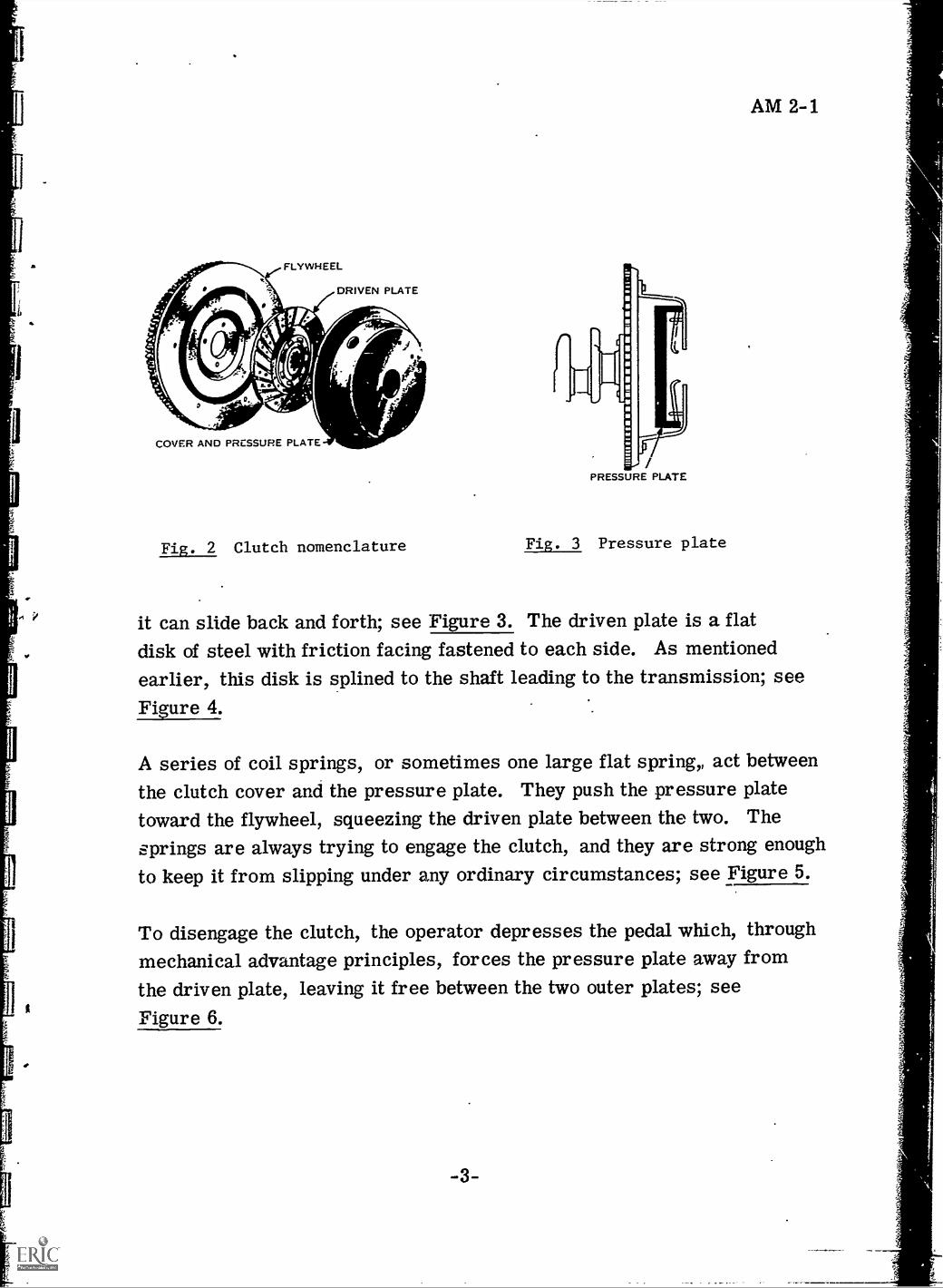
The engine flywheel is used for the first driving member (plate). Its sur-face is smooth where the driven plate pushes up against it. The otherdriving member is called the PRESSURE plate, see Figure 2. This plateis a heavy ring of cast iron, smooth on one side. It is fastened to thecover, which is bolted to the flywheel. It is fastened in such a way that
FLYWHEEL
DRIVEN PLATE
COVER AND PRESSURE PLATE
Fig. 2 Clutch nomenclature
/PRESSURE PLATE
Fig. 3 Pressure plate
AM 2-1
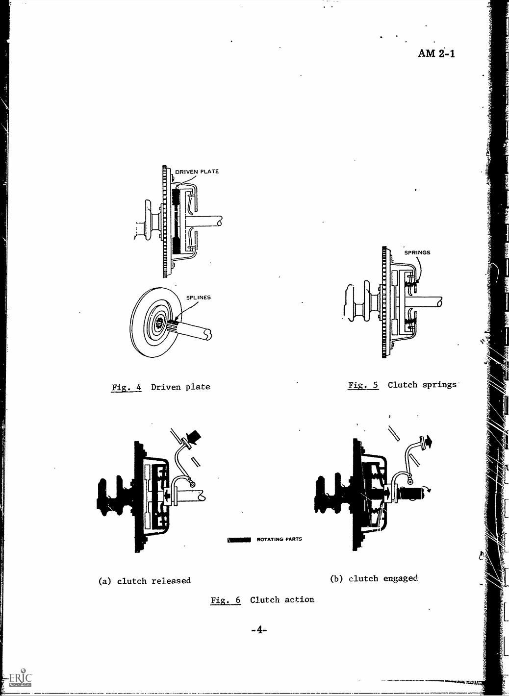
it can slide back and forth; see Figure 3. The driven plate is a flatdisk of steel with friction facing fastened to each side. As mentionedearlier, this disk is splined to the shaft leading to the transmission; seeFigure 4.
A series of coil springs, or sometimes one large flat spring,, act betweenthe clutch cover and the pressure plate. They push the pressure platetoward the flywheel, squeezing the driven plate between the two. The
springs are always trying to engage the clutch, and they are strong enough
to keep it from slipping under any ordinary circumstances; see Figure 5.
To disengage the clutch, the operator depresses the pedal which, throughmechanical advantage principles, forces the pressure plate away fromthe driven plate, leaving it free between the two outer plates; seeFigure 6.
-3-
DRIVEN PLATE
ILD
Fig. 4 Driven plate
(a) clutch released
MM. ROTATING PARTS
Fig. 6 Clutch action
Fig. 5 Clutch springs
,
r(b) clutch engaged

w
A
SECTION B -- TYPES OF CLUTCHES
AM 2-1
SINGLE DISK CLUTCH -- The single disk clutch is essentially the type
discussed in the previous paragraphs. The driving members of this clutch
consist of the flywheel and the driving (pressure) plate. It has one driven
member, faced on both sides with friction material, and is splined to the
transmission shaft.
DOUBLE DISK CLUTCH -- The double disk clutch is essentially the same
type except it has another driven disk and an intermediate driving plate;
see Figurel.
DRIVEN DISK PRESSURE FLYWHEELPLATE SIDE DRIVEN DISK FLYWHEEL SIDE
FLYWHEEL RING ASSY1.
INTERMEDIATE GEAR
HUB..s.
:3
I --, I
3
141,
ko/1"---.- --LOC K WASHER
'C1` P SCREW
Fia. 7 Double disk clutch
DRIVING PINPILOT BEARING

AM 2-1
MULTIPLE DISK CLUTCH -- This type clutch has more than three plates
or disks. Some have as many as eleven driving plates and ten driven
disks. Because the multiple disk type has a greater frictional area than
a plate clutch, it is best suited as a steering clutch on crawler tractors.Also, it sometimes is used on heavy trucks. In operation, it is very muchlike the plate clutch and has the same release mechanism. The facings,however, usually are attached to the driving plates rather than to the driven
disks. This reduces the weight of the driven disks and keeps them fromspinning after the clutch is released.
HEAVY DUTY CLUTCHES -- Most heavy duty vehicles today use automatictransmissions which call for a different clutch arrangement than has been
discussed so far. In units to follow we will cover automatic transmissionsand what is sometimes called the hydraulic coupling, or fluid flywheel type
of clutch.
Heavy duty clutches used with mechanical transmissions are somewhatdifferent then we normally think of a clutch in an automobile. Naturally,they are designed to handle more torque and all parts are readily re-placeable. One such cluth is the FLYWHEEL CLUTCH shown in Figure 8.
This clutch is used on the No. 12 CAT motor grader. All other vehicles(CAT), including the No. 14 motor grader, use the power shift (automatic)transmission and clutch arrangement which will be discussed later.
NOTE: For items mentioned in the following paragraphs, refer to Figure 8.
The oil type flywheel clutch is mounted to the engine flywheel (1) and
transmits engine power to the transmission when it is engaged. The clutchis located in the clutch and transmission housing, which is bolted to theflywheel housing. The clutch contains two driven disks (3) and (17), onedriving disk (4), and a driving plate (1.8).
IC
ti
u1
AM 2-1
2 r-
tArmr:Nw.,01,
lo
I
MIME
kig461Lit
1._
_r
12
14
, --16 17 L__ 18 19 20
11.
13
15
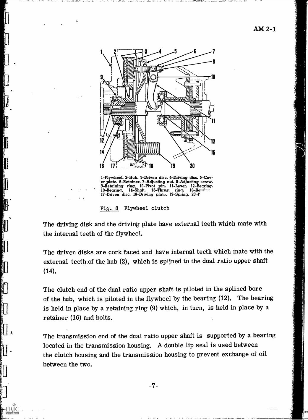
1-Flywheel. 2-Hub. 3-Driven disc. 4-Driving disc. 5-Cov-er plate. 6-Retainer. 7-Adjusting nut. 8-Adjusting screw.9-Retaining ring. 10-Pivot pin. 11-Lever. 12-Bearing.
, 4 13-Bearing. 14-Shaft. 15-Thrust ring. 16-R0,4--17-Driven disc. 18-Driving plate. 19-Spring. 20-F
Fig. 8 Flywheel clutch
The driving disk and the driving plate have external teeth which mate withthe internal teeth of the flywheel.
The driven disks are cork faced and have internal teeth which mate with theexternal teeth :of the hub (2), which is splined to the dual ratio upper shaft
(14).
The clutch end of the dual ratio upper shaft is piloted in the splined boreof the hub, which is piloted in the flywheel by the bearing (12). The bearingis held in place by a retaining ring (9) which, in turn, is held in place by aretainer (16) and bolts.
The transmission end of the dual ratio upper shaft is supported by a bearinglocated in the transmission housing. A double lip seal is used betweenthe clutch housing and the transmission housing to prevent exchange of oil
between the two.

AM 2 -1
Springs (19), which are located between the clutch cover plate (5) and thedriving plate (18), hold the clutch in the engaged position by clamping thedriven disks tightly between the driving disk and the flywheel. Depressingthe clutch pedal disengages the clutch by acting through linkage to movethe release bearing cage (20) toward the levers (11). The thrust ring (15),each one to pivot at its pivot pin (10), which is anchored to the clutch coverplate. Retainers (6), and adjusting screws (8), held in place by adjustingnuts (7), move, compressing the springs between the clutch cover and thedriving plate, which releases the pressure on the driven disks.
When the clutch is disengaged, the driving disk, driving plate, clutch coverplate, release levers, thrust ring and the bearing (13) continue to rotatewith the flywheel.
The clutch brake is actuated by the clutch pedal. The farther the pedalis depressed, after the clutch is fully released, the more the brake isapplied.
NOTE: For items mentioned in the following paragraphs, refer to Figure 9.
As the release bearing cage (20) moves toward the flywheel, it draws thebrake plate (22) toward the flywheel by means of two spring-loaded studs(26). The brake plate moves toward the flywheel on locating pins (21),partially compressing the springs (27) and clamping the brake hub (24)between the brake plate and the bearing cage support (23).
As the brake plate contacts the brake hub, further depressing of the clutchpedal will compress the spring (25), thus exerting pressure against thebrake hub. Since the brake hub is splined to the dual ratio upper shaft,the shaft and also the transmission gears are slf,Red down accordingly,or stopped entirely to allow gear shifting. Braking effort is limited bythe spring load.

J.
20
25 2S 2120-Bearing cage. 21-Locating pin. 22-Plate. 23-Bearingcage support. 24-Hub. 25-Spring. 26-Stud. 27-Spring.
Fig. 9 Clutch brake (cross section)
NOTE: For items in the following paragraphs, refer to Figure 10.
LUBRICATION IN THE FLYWHEEL CLUTCH -- Oil from the enginelubricating system is supplied to the flywheel clutch through the line (7)from the lower section of the diesel engine oil pump. The oil travelsthrough a passage in the flywheel housing (1) and enters the flywheel (2)through an annular groove which is cut into the outer diameter of theflywheel hub. Drilled passages (6) carry the oil through the flywheel.An oil thrower (3) on the clutch side of the flywheel directs the oil to theinner diameter of the clutch hub (4).
Slots in the hub direct the oil flow radially across the clutch friction sur-faces. Holes (9) in the outer edge of the flywheel and cutouts in the clutch

AM 2-1
1-Flywheel housing. 2-Flywheel. 3-0i1 thrower. 4-Hub.5-Cup. 6-Drilled passage. 7 -Oil supply line. 8-Oil return
line. 9- Holes. 10-Opening. 11-Clutch cover plate.12-Brake support plate.
Fig. 10 Flywheel oil clutch lubrication
cover plate (11) allow oil to be thrown against the walls of the flywheelhousing. The flywheel acts as a slinger and directs oil toward the opening(1) in the bottom of the flywheel housing. Oil from the bottom of thehousing is carried through a passage in the flywheel housing to the line(8). The oil flows through the line to the scavenger pump section of thediesel engine oil pump, where it is returned to the diesel engine crank-case.
Part of the oil thrown onto the inside of the clutch housing is directed downto the clutch brake by two ribs which are cast into the top inside surfaceof the clutch housing. The oil drains into a cup (5) which is cast into thetop of the brake support (12). The cup acts as a catch basin and deliversoil to all parts of the clutch brake. After lubricating the brake, the oilthen drains to the bottom of the flywheel housing, where it is picked up Andreturned to the engine oil sump.
-10-

AM 2-1,
Holes (see Figure 11 (13) in the flywheel housing permit oil to travelbetween the flywheel housing and diesel engine crankcase.
Because all parts of the flywheel clutch are splash lubricated, no externallubrication of the release bearing or pilot bearing is required.
10-Opening. I3-Holes.
10
Fig. 11 Flywheel housing openings
SECTION C -- COMPONENT PARTS OF THE CLUTCH
FRICTION DISK -- The friction disk (see Figure 12) consists of a huband plate assembly, to which is attached a series of facings. The diskusually includes a cushioning device as well as a dampening device. Thecushioning device provides a cushioning effect as the clutch is engaged, sothat smoother engagement results. The cushion springs, to which the facingsare mounted, (see Figure 12) provides this effect by compressing slightlyas the clutch engages, thus preventing a shock to the power train.

AM 2-1
g:' n''i*.',C'7'''
'r
i..:.-,,,--
4-..
z,1,4,,S..:fi::"
i
'0,e,p.-4c:*-....:1.U.:.-- N35:,>-:-. alcr-
,4,.-.-.t'-4lgg410AMIO ft
rz..- .c*,,,-a:6:41-'4.75 -1?"-1 4"t'f,e *'3efR;;z it5?a-7:,,,a722R -:/. C: 'e.7-;-,ei4-` -7..,e7,4,
::34. r.4t,_pi,4.k4,......44,.. ..,--x--'.-iit,... .,
:,/_-?!..,;%1",lov,c; --t...2:
-0"r.. -:eY...-t:K
%.~-`'I-v -.7' : ; .:7.-k-Z.: i, 0 ,1 - _ -, .X:- VICt'
:,,I..-.. ' .. . . .% ..
:1":7:9 .e c,1--_P.---1.::-'1'' '54 ,I.4*- '4..
l'.:4.....- --._ "... *' t. je71770::. : i44
' :' < . t t' c --,;:--.11.74
.s."... , ..mr s. L' :-; Via-e-.2":0'IcZe+ ;:lA
.15.1
.4.1.: e*ir
. ,
Fig. 12 Friction disk or driven plate
The dampening device uses a series of torsional coil springs placed betweenthe drive washers and riveted to the cushion springs and hub flange. Thedisk hub is thus driven through the springs, and they absorb a certainamount of torsional vibration. Stop pins limit the relative motion betweenthe hub flange and the drive washers. A molded friction ring, compressedbetween the hub flange and the drive washers, provides frictional dam-pening that prevents oscillation between the hub flange and the drive washers.
CLUTCH BEARINGS -- The friction clutch requires two bearings, one tosupport the clutch shaft in the flywheel web or the end of the crankshaft,the other for the throw-out collar. The bearing at the front end of the
-12-

AM 2-1
clutch shaft, which carries comparatively little load, is frequently anannular ball bearing; but sometimes cylindricalroller bearings also areused, and some use plain oilless bushings. The bearing is pressed intoa counterbore in the end of the crankshaft (or the bore of the flywheel web),and the inner race slips over the clutch shaft without being fixed axially, asany end thrust on the shaft is taken up on the bearing at its opposite end,which is secured to the wail of the transmission housing. The bearing at theforward end of the clutch shaft is usually packed in grease. It can also belubricated from the engine lubricating system through drill holes in thecrankshaft. In any case, provision must be made so that none of the lubricantsupplied to this bearing gets to the friction surfaces of the clutch.
To counteract oil getting to the clutch facings, the flywheel has a groovewith a drain hole which catches any oil which has dripped or has beenthrown by centrifugal force from the rotating parts. In addition, an oilslinger may be provided on the clutch driven member. This consists of apan-shaped stamping with a hole in the center, which is secured with its"bottom" to the hub of the driven disk, and is so proportioned that any oilthrown from its edge is caught in the oil groove in the flywheel rim.
Occasionally, a radial ball bearing is used for the clutch throw-out collar,but as the load is a straight thrust load and radial bearings have relativelylittle thrust capacity, it must be made comparatively large. The one thingin favor of radial bearings for this application is that they are lesssensitive to centrifugal force on the balls than other types. Special designsof angular-contact and thrust ball bearings have been developed for thispurpose. The bearing on the clutch throw-out collar shown in Figure 13 (a),is a New Departure product. It is provided with a heavy inwardly-turnedflange on the outer race, against which the clutch levers may bear, andwith a steel shell forming a lubricant reservoir which is permanently fixedto the outer ring. The shell is made to hug either the projecting portionof the inner race or the throw-out collar. For use with clutches in whichthe levers are in the form of flat steel springs, the flange on the outer racewith which the levers contact is made convex. Other clutch throw-out
-13-

Fig. 13 Types of bearings
(b)
AM 271
bearings of the angular-contact type are made with a radial flange on theinner race, to suit special mounting conditions.
The BCA throw-out bearing, on the throw-out collar illustrated inFigure 13 (b), is of the angular-contact thrust type, the line of contactmaking a small angle with the axis of the bearing. A steel sheel issecured to the outside of one race and cupped over the other. ' This latterrace is located against a shoulder on the throw-out collar, while the outerface of the outer race will contact the clutch levers.
THROW-OUT COLLAR -- The clutch throw-out collar can be arranged toslide either directly on the clutch shaft, on a flanged tube extending forwardfrom the transmission housing and surrounding the clutch shaft, or in a
hub formed on or secured to the clutch cover plate. Having the collar slidedirectly on the clutch shaft is open to the objection that with this arrangementthere is high velocity sliding motion between the parts whenever the engine
is running and the clutch is engaged, which necessitates thorough provisions
for lubrication and entails wear on the bearing surfaces.
-14-

AM 2-1
When the collar slides on a tube secured either to the transmission housingor to the clutch cover plate, the only sliding motion between contacting partsis that due to clutch engagement or disengagement. The clutch collar isgenerally provided with an oil pocket, from which an oil hole extends to itsbearing surface, and it is chambered out at the middle of its length toprovide an oil reservoir. Oiling generally is effected through a tubeprotruding through the wall of the clutch housing and having a lubricatorfitting at its end, the inner end of the tube being located over the oil pocket.Where no such provision is made, the clutch collar can be lubricated byremoving the cover on the clutch housing. To prevent rattling, a springis provided which draws the clutch collar against the throw-out yoke.
CLUTCH FACINGS (HEAVY DUTY) -- Clutches used in heavy dutyvehicles have facings of spirally-wound asbestos yarn and brass wire,impregnated with compound, with a layer of copper-asbestos compound(molded to it). The copper-asbestos is the friction surface and con-stitutes about one-half the total thickness. The surface of this lining isof copper color, while the back is covered with an aluminum compoundto improve the heat-radiating qualities. These facings are much lighterthan metallic facings, and can be riveted to the disk in the same manneras ordinary "woven" facings.
Metallic facings are used to a certain extent in heavy duty service. Thehigh heat conductivity of such facings tends to prevent excessive temperaturesin multiple-disk clutches; their frictional properties are practicallyunaffected by high temperatures; and their rate of wear is said to berelatively low.
PEDALS AND PEDAL LINKAGE -- ClUtch pedals vary in height from 14to 18 inches, while the yoke arms on the pedal shaft, which press againstthe clutch throw-out collar, measure from 1 1/4 to 2 1/2 inches. In thecase of clutches of comparatively low torque capacity, the clutch pedaloften is mounted directly on the shaft of the clutch throw-out yoke which
-15-

AM 2 -1
extends through the wall of the clutch housing. Large clutches are notbuilt this way because it is difficult to obtain enough leverage to bring therequired clutch pressure within the desired range of 20 to 30 ths. Oneremedy to this is using compound clutch levers as shown in Figure 14.Another method is to use a hydraulically operated clutch; this typewill be discussed in AM 2-1D film.
Fig. 14 Compound clutch lever
SECTION D -- CLUTCH ADJUSTMENT AND TROUBLESHOOTING
CATEGORIES -- Clutch troubles usually are fairly obvious to the mechanicand fall into one of the following categories: slipping, chattering orgrabbing when engaging, spinning or dragging when disengaged, clutchnoises, clutch-pedal pulsations and rapid friction disk facing wear.
SLIPPING of the clutch while it is engaged is extremely hard on the clutchfacings. The facings wear and burn badly; so a slipping clutch may soonbecome completely inoperative.
Clutch slippage is particularly noticeable during acceleration, especiallyfrom a standing start or in low gear. A rough test for clutch slippage can
-16-

AM 2-1
be made by starting the engine, setting the hand brake, shifting into highgear, and then slowly releasing the clutch pedal while accelerating theengine slowly. If the clutch is in good condition, it should hold so thatthe engine stalls immediately after clutch engagement is completed.
Several conditions can cause clutch slippage. The clutch linkage may notbe properly adjusted. With an incorrect adjustment that reduces pedallash too much, the throw-out bearing will still press against the releaselevers, even with a fully released clutch pedal. This takes up part of thespring pressure; the pressure plate will not exert sufficient pressure tohold the friction disk tightly enough against the flywheel. As a result,there is slippage between the surfaces. The correction here is to re-adjust the linkage.
If the clutch-release linkage binds, it may not return to the fully engagedposition when the clutch pedal is released. This, of course, causesclutch slippage. Binding can be eliminated by lubricating all points offriction in the linkage and realigning and readjusting the linkage ifnecessary. If readjusting, lubricating, and freeing the linkage do noteliminate the slippage, then the trouble is probably inside the clutchitself, and this requires removal of the clutch from the vehicle so that itcan be disassembled for service. Conditions in the clutch itself thatcould cause slippage include the following.
Weak or broken pressure spririgs (or diaphragm spring) will not exertsufficient pressure; new springs should be installed. Worn friction-diskfacings or grease or oil on the disk facings will permit slippage; thefacings or the complete disk should be replaced if this is the case.
Incorrectly adjusted release levers (adjustable type) may act in the samemanner as an incorrectly adjusted clutch linkage or a binding clutch-release linkage. That is, they may prevent full spring pressure on thepressure plate, with a resulting clutch slippage. Release levers mustbe adjusted as explained in the applicable manufacturer's shop manual.
-17-

CLUTCH CHATTERS OR GRABS WHEN ENGAGING -- As a rule, thistrouble is inside the clutch itself, and the clutch will have to be removed.Before this is done, however, the clutch linkage should be carefullychecked to make sure it is not binding; if it binds, it may releasesuddenly to throw the clutch into quick engagement, with a resulting heavyjerk.
In the clutch, the trouble could be due to oil or grease on the disk facingsor to glazed or loose facings. Also, binding of the friction-disk hub onthe clutch shaft could prevent smooth engagement of the clutch; thiscondition requires cleaning up of the splines in the hub and on the 'shaft andlubrication of the splines. Broken parts in the clutch, such as broken diskfacings, broken cushion or coil springs in the friction disk, or a brokenpressure plate, could cause poor clutching action and grabbing.
CLUTCH SPINS OR DRAGS WHEN DISENGAGED -- The clutch frictiondisk spins 11riefly after disengagement when the transmission is in neutral.It takes a moment for the friction disk to come to rest. This normalspinning should not be confused with a dragging clutch. When the clutchdrags,.. the friction disk is not being fully released from the flywheel orpressure plate as the clutch pedal is depressed; the friction disk continuesto rotate with or to rub against- the flywheel or pressure plate.
The first thing to chece: with this condition is the pedal-linkage adjustment.If there is excessive pedal lash, or "free" travel, even full movement ofthe pedal to the floorboard will not force the throw-out bearing in againstthe release levers (or diaphragm spring) far enough to release the clutch
fully. If adjustment of the linkage to reduce pedal lash, or free travel,does not correct the trouble, the trouble is in the clutch, and the clutchmust be removed for disassembly and service.
In the clutch, the trouble could be due to a warped friction disk or pres-sure plate, or to a loose friction-disk facing. On the type of clutch with
-18-

ADA 2 1
adjustable release levers, improper adjustment would prevent full dis-engagement, so that the cluteh would drag. The friction-disk hub maybind on the clutch shaft so that it does not move back and forth freely.The result is that the friction disk rubs against the flywheel when theclutch is released. Binding may be relieved by cleaning up the splineson the shaft and in the hub and lubricating the splines.
CLUTCH NOISES -- Clutch noises ustially, are most noticeable whenthe engine is idling. To diagnose clutch noises, first note whether it isheard w hen'the clutch is engaged or when the clutch is disengaged.
Noises that come from the clutch when the clutch is engaged could bedue to a friction-disk hub that is loose on the *clutch shaft. This wouldrequire replacement of the disk or clutch shaft, or perhaps both if bothare excessively worn. Friction-disk dampener springs that are brokenor weak will cause noise, and this requires replacement of the completedisk. Misalignment of the engine and transmission will cause a back-ward-and-forward movement of the friction disk on the clutch shaft;
. , ,
alignment must be corrected.
Noises that come from the clutch when it is disengaged could be due toa clutch throw-out bearing that is worn, is binding, or has lost itslubricant. Such a bearing squeals when the clutch pedal is depressedand the bearing comes into operation. The bearing should be relubricatedor replaced. If the release levers are not properly adjusted, they willrub against the friction-disk hub when the clutch pedal is depressed. Therelease levers should be readjusted. If the pilot bearing in the crankshaftis worn or lacks lubricant, it will produce a high-pitched whine when thetransmission is in gear, the clutch is disengaged, and the vehicle isstationary. Under these conditions, the clutch shaft, which is piloted inthe bearing in the crankshaft, is stationary, but the crankshaft and bearingare turning. The bearing should be lubricated or replaced.
- .19 -

AM 2 -1
CLUTCH-PEDAL PULSATION -- Clutch-pedal pulsation, sometimescalled a nervous pedal, is noticeable when a slight pressure is appliedto the clutch pedal with the engine running. The pulsations can be feltby the foot as a series of slight pedal movements. As thd pedal pres-sure is increased, the pulsations cease. This condition is often anindication of trouble that must be corrected before serious damage tothe clutch results. One possible cause of the condition'is misalignmentof the engine and transmission. If the two are not in line, the frictiondisk or other clutch parts will move back and forth with every revolution.The result is rapid wear of clutch parts. Correction is to detach thetransmission, remove the clutch, and then check thp housing alignmentwith the engine and crankshaft. At the same time, the flywhee that isnot seated on the crankshaft flange, will alSo produce clutch-pedalpulsations. A flywheel that is not seated on the crankshaft flange shouldbe removed and remounted to make sure that it does seat evenly, Ifthe flange itself is bent, then a new flange, or crankshaft, is required.
If the clutch housing is distorted or shifted so that alignment betweenthe engine and transmission has :been lost, it sometimes fs possible torestore alignment by installing shims between the housing and engineblock and between the housing and transmission case. Otherwise, a newclutch housing will be required.
Other causes of clutch-pedal pulsations include uneven release-leveradjustments (so that release levers do not meet the throw-out bearingand pressure plate together) and a warped friction disk or pressureplate. Release levers (adjustable type) should be readjusted. A warpedfriction disk usually must be replaced. If the pressure plate is out ofline because of a distorted clutch cover, then the cover sometimes canbe straightened to restore alignment.
RAPID FRICTION-DISK-FACING WEAR -- Rapid wear of the friction-disk facings rill be caused by any condition that permits slippage between
-20-

AM 2-1
the facings and the flywheel or pressure plate. Thus, if the driver hasthe habit of "riding" the clutch (that is, if he keeps his foot resting onthe clutch) part of the pressure-plate spring pressure will be taken up sothat slipping may take place. Likewise, frequent use of the clutch orexcessively slow releasing of the clutch after declutching will increaseclutch-facing wear. The remedy here is for the driver to use the clutchproperly and only when necessary.
Several conditions in the clutch itself can cause this trouble. For example,weak or broken pressure springs will cause slippage and facing wear.In this case, the springs must be replaced. If the pressure plate or frictiondisk is warped or out of line, it must be replaced or realignment mustbe reestablished. In addition to these conditions in the clutch, improperpedal-linkage adjustment or binding of the linkage may prevent full springpressure from being applied to the friction disk. With less than fullspring pressure, slippage and wear are apt to take place. The linkagemust be readjusted and lubricated at all points of friction.
CLUTCH PEDAL STIFF -- A stiff clutch pedal, or a pedal that is hardto depress, is likely to result from lack of lubricant in the clutch linkage,from binding of the clutch-pedal shaft in the floorboard seal, or frommisaligned linkage parts that are binding. In addition, the overcenterspring (on vehicles so equipped) may be out of adjustment. Also, if theclutch-pedal has been bent so that it rubs on the floorboard, it may notoperate easily. The remedOin each of these -eases is obvious: parts mustbe realigned, lubricated, or readjusted as necessary.
CLUTCH-PEDAL ADJUSTMENT -- Clutch-pedal-linkage adjustment maybe required from time to time to compensate for friction-disk-facingwear. Also, the linkage requires periodic lubrication. The adjustmentmust provide the proper amount of free clutch pedal travel (also calledpedal lash). The free travel is the pedal movement before the throw-out bearing comes up against the clutch release levers. After this occurs,there is a definite increase in the amount of pressure required to actuate
-21-
AM 2-1
the release levers and disengage the clutch. If the pedal lash is too great,the clutch may not release fully, and this could cause clutch spinning during
disengagement. If the pedal lash is too small, the clutch may not be ableto engage fully, and this could cause rapid friction-disk-facing wear.Methods of making the adjustment vary in differentvehicles. Refer to themanufacturer's shop manual for details and specifications.
INSPECTING AND SERVICING CLUTCH PARTS -- The various clutch
parts can be checked as follows when they are removed from the clutch:
1. Clutch pressure springs -- If the pressure springsavefint will burn off or the springswill turn blue. Overheated springs should be replaced,since they may have lost tension and will not operatesatisfactorily. Spring pressure can be tested witha spring-tension tester.
2. Pressure plate -- A warped or badly scored pressureplate should be replaced. Slight scores or scratchescan be cleaned off with fine emery cloth: All tracesof emery should be removed.
3. Friction disk -r- The friction disk should be care-fully inspected to make sure that it is in good condition.Several points should be considered.
CAUTION: Do not get any trace of oil or grease on the friction-diskfacings. Even small traces may cause clutch grabbing or slipping.
FACINGS -- If the facings are worn down nearly to the heads of the
rivets, then the facings or friction disk should be replaced. Many
manufacturers recommend replacement of the complete disk;some supply facing-replacement data along with strong cautions to beextremely careful if installation of new facings on the disk is attempted.
CUSHION SPRINGS -- If the cushion springs under the facings appear to
be cracked or weak, the friction disk should be replaced.
TORSIONAL SPRINGS -- Torsional springs that are loose, and seem tohave lost tension, require replacement of the complete friction disk.
-22-

Ir
AM 2-1
HUB SPLINES -- The fit of the hub to the clutch shaft should be tested.It should slide without difficulty and should not have any noticeablerotary play. Excessive play means worn splines, and either the shaftor the disk should be replaced (or both).
THROW-OUT BEARING -- The throw-out, or release, bearing shouldnever be cleaned in any cleaning solvent or degreasing compound, sincethis would remove the lubricant that is placed in the bearing on orignialassembly and would thereby ruin the bearing. If the bearing runs roughlyor seems loose or noisy, it should be replaced.
HOUSING ALIGNMENT -- Normally, there need be no concern aboutthe clutch-housing alignment, since it was correct on original assembly,and alignment should not be lost even if the transmission has been re-moved and replaced. However, if clutch-pedal pulsations are noticedor if gear shifting is hard and gears jump out of mesh, then alignmentshould be checked. This requires a special alignment arbor and dialindicator.
PILOT BEARING IN CRANKSHAFT -- The pilot bearing in the cranksahftusually is either a bushing or a ball bearing. The old bushing can beremoved and a new one installed with a special tool. A small amount ofshort-fiber grease should then be placed in the bushing. Do not putany kind of grease on the end of the clutch shaft.
HEAVY-DUTY FLYWHEEL CLUTCH ADJUSTMENT -- Figure 15 showspoints of adjustments on the CAT No. 12 Grader flywheel clutch. Upon
installation of this clutch, turn adjusting nuts (1) until there is a 1/8"clearance at (A) between the clutch release levers and the face of thethrust ring. Install a cotter pin in each adjusting screw to lock the nut.
& With no pressure on the clutch pedal, adjust the linkage between the clutchpedal and the clutch until there is . 010" to . 015" clearance at (B) betweenthe release yoke arms and the buttons on the bearing cage assembly.
-23-

1-Adjusting nut. 2-Lockuut. 3-Adjusting nut. 4-Interlockcontrol rod. 5-Interlock housing. A-Vs" clearance at
this point. B-.010" -.015" clearance at this point.C-2 1/16" dimension earlier machines or
1.81" dimension later machines.
Fig. 15 Flywheel clutch assembly
AM 2-1
After the clearances are obtained at (A) and (B) and with the clutchengaged, loosen the locknut (2) and turn the adjusting nut (3) as requiredto obtain the measurement (C), between the center of the lower pin of theinterlock control rod (4) and the top of the interlock housing (s). Tightenthe locknut securely after the adjustment is completed.

DIDACTOR PLATES FOR AM 2-1D
METALTUBING
CLUTCHMASTER CYLINDER
BODY
SPRING
SEAL
AM 2-1D
FLEXIBLEHOSE
Plate I
METALTUBING
CLUTCHMASTER CYLINDER
Key
SPRING
SEAL.
FLEXIBLEHOSE
PISTON
BLEEDSCREW
1) V
SHIM
CUP
i
RUBBERBOOT
LINK
6 SLAVECYLINDER
SPRING
RUBBERSEAL CUP LOCK NUT
PISTONRUBBER
BOOTPlate II
PUSH ROD
LOCK NUT
ADJUSTINGNUTI
LINK

Gears A and C have 12 teethgears B and D have 24 teeth(gear A is turning as indicated).
Plate III Gear problem-
- 2

DIDACTOR
a
PAGE no./
AM 2-1D1/5/67
LEARNING ABOUT MECHANICAL CLUTCHES
Human Engineering Minn. State Dept. of Ed.Institute Vocational Education
Press A I Check to see that timer is OFF
As we have learned, mechanical clutches are usedwith mechanical transmissions. In a transmission ofthis type the operator must shift the gears manually.The mechanical clutch in this type of power trainenables the operator to ..
3 A. increase or decrease the engine torqueoutput
6 B. gradually allow engine torque to be appliedto the load
C. delay torque until engine builds up rpm
1-1
FILM no. 4M,1,:c177.114jr 11.
This film lesson is designed to supplement class textAM 2-1 by reviewing some basic knowledge behind themechanical aspects of the CLUTCH. In addition. anintroduction to transmissions will be presented byrenewing GEARING principles. As you proceed throughthis lesson read each frame carefully and think beforeanswering the questipns.
Press A 2.. 1-2
No. You :Fp incorrect. Engine torque t annot bechanged by the clutch. Torque is designed into the engine(1, e, small engines have low torque. large engines havehigh torque etc, )
The operator can use the clutch as a means to changeinto various gears: this is one reason for the clutch.but not the answer we want here. Try this question
again.
1-3
No. Delaying torque until a certain rpm isreached is not the purpose of the clutch. It
can be used in this manner but it is definitelynot recommended. Try this question again.
OK. The clutch is a mechanism that allows theengine to take-up the load gradually and withoutshock, The clutch also provides a means fordisconnecting power (torque) from the load, forgear shifting purposes. a simple one discclutch arrangement. the engine flywheel servesa plate,
Press 13 2_
No. The flywheel is called one of thedriving platesin this type of clutch.. The flywheel is attached tothe engine crankshaft.
The other driving plate is attached to the flywheel,Hence, when the crankshaft rotates, both drivingplates rotate.
Press A tr
N9... The pressure plate is the other drivingplate. Strong springs force the two drivingplates together, squeezing the driven plate untilall plates are turning as a unit,
Press 13 r

DIDACTOR PAGE no. g
OK. The flywheel serves as one of the driving plates.The other driving plate is fastened to the flywheel.Both are attached to the engine crankshaft. Thisstatement is
/ A. True41 B. False
(NOTE: You must select the correct answer beforethe next frame will appear).
1-9
-,.....r......PrOWIMM.W.P.,...1
When the pedal is completely let out (no footpressure), the spring pressure is at maximum,the speed of the driving plates and the drivendisks are the same, and all slipping stops. Atthis time there is a direct connection,betweenthe driving and driven shafts.
Press A I C
A cylinder, similar to a single acting brakewheel cylinder, is connected to the mastercylinder by pressure hose or metal tubing; seePlate IL The slave cylinder is connected to theclutch release yoke lever. Movement of theclutch pedal actuates the clutch master cylinder.This movement is transferred-by hydraulicpressure to the slave cylinder, which in turnactuates the clutch release yoke lever.
Press A I 2- 1-13
No. Your answer is only partially correct.The hydraulic clutch, just as the hydraulicbrake, uses these mechanical advantage andleverage principles. But, in addition, thereis a hydraulic power assist that makes it easierto depress the clutch pedal.
Press A Cif1-15'
Am 2,4DFl LM no. 1/5/67
OK. The engeging pnd disengaging of the clutch iscontrolled by two factors: the series of springsconstantly trying to engage the clutch; and the pedal-operator combination disengaging the clutch. As theoperator depresses the pedal, the spring tension isovercome and the clutch is allowed to slip. When thepedal is depressed all the way, the driving and drivenplates are separated entirely.
Press A 9,
In most clutches, there is a direct mechanicallinkage between the clutch pedal and the clutchrelease yoke lever.
On some hayy clutch installations, where a greatamount of pressure is required, a hydraulic clutchrelease system isused; see Plate I. A mastercylinder, similar to a brake mister cylinder,is attached to-the clutch pedal.
Press B 1-12
Just as in a hydraulic brake system, ahydraulic clutch system uses_
a means of depressing the clutch springs.
1-3 A. mechanical advantage
I ,3 B. leverage principle
ie C. hydraulic power assist plus A and B
OK. Where there is a hydraulic system of any type,there must be a pump. Look at Plates I and IIcarefully. The pump in this arrangement is the
(1) which is actuated by the (2)action.
/.51.A. (1) slave cylinder/4 B. (1) master cylinder/41C, Both A and B are wrong
(2) master cylinder(2) pedal
1-16

DIDACTOR PAGE no.S111.111.111111.11111=1111111111111011111MINIPIIMPIINIFINOir
No. The correct answer is: the master cylinder isthe pump which it actuated by the pedal.
When the pedal is depressed, it form the mutercylinder piston to move so as to compress oil in thecylinder. This action forces oil under pressurethrough tubing-to-the slave cylinder, which in turnactuates the clutch release-yoke lever.
Press A I
15v
You have answered one or more of the questions inthis sequence incorrectly. Before going on to flewmaterial, read this section again. Tike your timein answering the questioni.
Press A 22-2
pr.riftfts..a.monvanftimoprserveerlommoollmoids10+;Pmemmol
OK. It is desirable to hold spinning of the drivenplates to a minimum after clutch releaSe tci
2 0 A. reduce wear on the drive shaft bearings
1. 1 B. allow easier shifting of gears
e C. Both A and B are incorrect .
2-14
AFILM nck
lt2;1D1/5/er
I'Olt.' When the pedatis depressed, oil is compressed bythe meter cylinder piston and pressurised oil moves theslavcylinder push rod, width in turn moves the clutchrelease yoke lever.
We have discussed the multipiedisk clutch. lraeings onfrictional surfaces is these. clutches usually are attachedto the driving plates rather than the driven plates. Thestain reason tsr this is to
g- A. gain more friction,greater heat dissipation, anda more positive contact
/41 reduce the_weight of the driven disks so spinningcan be held to a minimum after the clutch is 2.4released
dia (C)
No. You are incorrect. The fact that frictionalsurfaces arelattached to the driving plates will notafford more frictional surface nor have any higherheat dissipation capabilities.
The correct answer Is: to reduce the weight orthedriven disks, to keep them from spinning after clutchrelease.
Press A
L
6
OK. You will retell we mentioned that the CAT.No. 12 Grader clutch had a brake arrangement toMow down, and even stop. the drive shaft tofacilitate shifting the gears.
2/
The cushioning device that most friction clutches haveconsists of
A. a series of coil springs riveted to the pressureplate
B. a throw -out bearing mounted to the drive shaft
2 y C. waved cushion springs mounted in the drivendisc 2-6
oforiogsas:;:r,
No. To allow easier shifting of the tears. Is thecorrect answer. This also reduces wear on thegears in the transmission. You will recall. inour discussion of the CAT mechanical clutcharrangement. where a brake mechanism stoppedthe rotating shaft only for the purpose of shiftinggears.
Press A
voompo
20
No: These springs are not for dampening. Thecushioning device consists of waved cushionsprings to which the friction faces are attached.These springs compress slightly as clutchengagement moors,
Press A Ze,2-7

DIDACTORr
I
PAGE no. 1-/=1.1.
No. The throw-out bearirg moves up and down theshaft for another purpose.
The correct answer is: the cushioning device builtinto the friction plate consists of waved springs thatcompress slightly when clutch engagement occurs.
Press A 2 of 2-8
AM 2-1DFI LM no. 1/5/67
. 2 1/OK. The waved springs on which the friction facings areattached compress a little when clutch engagement occurs.
The danipeliirui effect comes from a series of coil springs(also mainted in-the friction Sisk) placed between thedrive washer:: and riveted to the trashion springs and hubflange.
there normally are (1) bearings in a friction clutch, oneto support the (2) and the other for the (3)
2_,( A. (1) two (2) friction disk (3) pedal movement24 B. (1) two (2) clutch shaft (3) throw-cut collarZS C. Answers A and B are both wrong.
No. You have chosen a wrong answer. Two bearingsare used, but one is to support the clutch shaft, andthe other is used for the throw-out collar.
Press A for another look at this one. 2
2-10
No. You are incorrect. This bearing frequently isan annular ball bearing which will take comparativelylittle radial load. Some clutch manufacturers use acylindrical roller bearing for this application. and stillothers use an oilless bushing.
Press A 2
27
2-12
27No. Radial load and vertical load are very similar andhere we need a thrust load type bearing. Remember,there are two types of force that act on bearings, radialand thrust. In some cases, there is a need for a combinationof both radial and thrust.
In this case, there is no radial force on the throw-outbearing, but -- due to the centrifugal force factor -- weneed a bearing that will accept angular contact.
Press A 3 0 2-14
. frvrwtir-v"~~7"""''"""
11.02-9
L
OK. The bearing at the front of the clutch shaft mustcarry a heavy radial load, due to the torsionalvibration and the weight of the crankshaft and clutchshaft. This statement is
27 A. TtueB. FIllse
2-11
False is correct. This bearing is required to take acomparati-veight radial load. The bearing is pressedinto a counterbore in the end of the crankshaft (or thebore of the Oyu heel web). and the inner race slips overthe clutch shaft. Any end thrust on the shaft is taken upon the bearings at the opposite end, which is securedin the wall of the transmission housing.
The clutch throwout bearing is subject to a straight thrustload as inflicted by the yoke. Since centrifugal force isa factor here, most throw-out bearings are of the
type.
30 A.z 9 B.
C.
1.1 -=111
angular contactradial loadvertical load 2-1 3
OK. Special designs of angular contact and thrust ballbearings have been developed for this purpose.
Clutch adjustment and troubleshooting -- As we learnedearlier, clutch problems usually are obvious to themechanic. Let's review a few problems that frequentlyoccur with mechanical clutches.
"Press A :24-
:fr)
414
3-1
11111

DIDACTOR PAGE mg'
You have missed one pr more el the questions in thissequence of material. Before going on, review thelast few frames. Take your time in answering thequestions.
Press A I co 3-2
No. To check the petprn springs or MiSalignMent ofthe engine and transmisition would require a completeteardawn of the unit. Remember, as has beenmentioned platy times before, check for simplethings first. In this case it may he pedal linkage,
Press A
f
airs.;
.001.
No. You are incorrect. A loose friction disk hubor a worn out clutch throw-out bearing would not causea clutch to slip.
If these two components were bad, there would be a lotof clutch noise.
Press A .
3-6
No. The mechanic can only guess whether the clutchhas been ridden excessively or not. Usually, if theclutch ha.s been treated in thiS manner, it will be shownby badly worn friction disks through overheating,
The answer we want here is: worn friction disks.Sometimes they are worn so badly that the rivets rubthe driving plates.
3 7" 8
Press
3,1bFILM not 1 /s/e7
IFillaWwwwwryrfrarrwmwr."FirrfrwlifFrwvwywowariwwwwwwymw."
Clutch slipping Irsquantly is a compliant when mechanicaltransraiffipna s.nd friction cltftches are ipstalied on avehicle, Stipppsq wet O one that was slipping badly.Probably thp first thing to do would be
..41../ A. remove the clutch and check the return springs
,?? 3 B. check for misalignment of the.engine and transmission
to checiF pedal linkage and readjust if necessary
3-3
OK, If readjusting, lubricating and freeing the linkagedoes not remedy. the situation, then the only thing leftto do is pull the clutch and check the internal workingS,
Qne condition inside the clutch that could cause slippingis
.0 A. a loose friction disk huh
,4, a worn out clutch throw-out bearing
310 C, Both A and are wrong answers
OX. These two conditions would nqt cause clutchslipping, Qne thing that may cause excessive slippingis weak or broken pressure springs.
Another would Iv_It 7 A. the operator riding the clutch
.? 9,B. worn friction disks
...t3g C. warped friction plate
r
3-7
NP, Unless the friction disks are worn, orthere has been grease or oil on the dislcs,therewill be little eloping of the clutch.
An excessively warped disk should he replacedimmediately.
Press A3-9

DIDACTOR PAGE no. &7 (..,
OK. Worn friction disks are common in the mechanical
clutch. Some get so bad the rivets that hold the frictionmaterial are rubbing the driving plates, just as brakelining rivets rub the drums when they get worn.
Either a binding clutch linkage or a sticking releasemechanism very often causes clutch problems. If thelinkage binds, then releases suddenly, clutch chatteringor grabbing will occur. This is caused by the drivendisk being squeezed too quickly.
Press A a Q 3-10
No. Noises heard when the clutch is disengaged usuallyare caused by the throw-out bearing being worn. Manytimes the bearing is binding and it has lost all lubricant.Try this question again.
Press A /../ C;
3-12
q./
OK. The driven disk will spin a little(due to centrifugalforce )after disengagement. However, clutch spinningin this sense is not clutch dragging, Clutch draggingoccurs when the friction plate "hangs up" against thedriving plates and will not release completely. In
troubleshooting this condition, a smart mechanic wouldfirst check
4-/q A. for weak cushion springs in the frictionti t. plate
B. pedal linkage adjustmentt.%.,r C , for a warped pressure plate
3-1'4
No. To check for a warped pressure plate would meanremoval of the clutch housing and disassembly,
Here again: check for Simple things first. Much timeand money can be saved by using the methodical approachto troubleshooting.
Try this one again.
Press A 4/3-16
AM 2-IDfl LM no. 1/5/67-
There is little clearance between the driven (friction)disk and the driving plates. Hence, when the clutchis released, by pushing in the pedal, all internal partsof the clutch must be in good shape. For instance, ifthe driven disk is warped, or has loose friction facings,you will get a condition of
if l A; clutch noises, commonly called squealing/-/Z 13. rapid wear on the friction facing1/3 C. clutch dragging when disengaged
3-11
Wm.111.111011.
No. Rapid wear on the friction plates is usuallycaused by excessive slipping, an indication that theoperator is -riding- the clutch or abusing It in someother manner. Try this question again.
Press A 41 C)
mmr..X.....".
1.1.
Art:/,Mn .
No. Weak cushion springs in the friction plate wouldnot cause clutch dragging.
.
If these springs are worn or broken. the result willbe clutch grabbing. or heavy jerking when the clutchis engaged.
Try this question again.
1.; 17%Press B 7-'1 - 1 ';
OK. The first thing to check with this condition Is thepedal linkage adjustment. If there is excessive pedallash, or free travel, even full movement of the pedalto the floor board will not force the throw-out bearingin against the release levers (or diaphragm spring)far enough to release the clutch fully; hence we getdragging.
Press B 4 7 3-17

DIDACTOR PAGE no.7
I
Let's talk about clutch noises, which are commoncomplaints with mechanical clutches. When trouble-shooting for clutch noise, the first step is to startthe engine
if Y. A. and rapidly release the pedal withthe transmission in low gear
I/1 B. depress the clutch fully, and shiftinto all gears, noting any mesh noise
/6 C. and note whether the noise is heard whenthe clutch is engaged or disengaged
3-18
No. Shifting from one gear to another with the clutchengaged would only be a partial test indicating ifnoise was present when the clutch is engaged (shiftingthe gears at this time is not necessary).
The answer we want here is: to leave the engine atidle and determine whether the clutch noise is presentwhen the pedal is out,or fully depressed.
/.%Press A .:-.)1) 3-20
r
11.1=.7.1MP
No. This would not help a condition of weak or brokendampener springs. The answer we want here is thatthe entire disk should be replaced. It is not feasibleto replace these dampener springs because, as welearned earlier, the friction face material is riveted
these springs.
Press B ( 9 3-22
That is correct. It is standard policy to replace theentire friction disk in most shops because of theriveted parts involved.
There is one condition where shims can be used tocorrect malfunctions in the clutch. This is when
the clutch pedal linkage is out ofadjestmentthere is misalignment of the engine andtransmissionthe friction disk hub is loose on the shaft 3-24
.,n)FILM no. 1/5 67
No. The proper procedure to test clutch noise isto first determine Whether the noise is heard whenthe clutch is engaged or disengaged with the engineidling. To rapidly release the pedal when thetransmission is in low gear would only stall theengine.
Press A :150 3-19
OK. There are several conditions that could causea noisy clutch when the cluck is engaged. One of thesecould be due to a friction-disk hub that is loose on theclutch shaft. Another condition is broken or weakdampener springs on the friction disk. To repairthis would require
16:7 A. tightening up of the friction disk hub
Z B. only replacing the springs in question
5/3 C. replacing the friction disk
3-21
No. It is not feasible to replace the weak or brokendampener springs because, as we learned earlier.the friction face material is riveted to these springsand the standard policy is to remove and replacethe entire friction disk or disks.
Press A 7
. , 0.10.101.4.T.
'3-23
No There are locknyts and other methods of pedaland linkage adjustments. The answer we want hereis that shims can sometimes be used to correct amisalignment between the engine and transmission.
Press A
3,25

DIDACTOR PAGE no.e
No. A loose disk hub would require the replacementof the friction disk or clutch shaft. The answer wewanted here is that shims can sometimes be usedwhere there is a misalignment between the trans-mission and engine.
Press A3-26
You have missed one or more of the questionsin this sequence of material. Review thissection, read carefully and take your time inanswering.
Press A 323-28
Foot-pounds used to describe torque measurement isactually a false statement.
Engineers classify the foot-pound asp unit of work orenergy. In other words a foot-pound is the amount of workdone when a mass of one pound is raised one foot againstgravity.
A pound-foot, on the other hand, is the action created whena force of one pound is applied to the end of a lever armone foot long.
Press A.4-2
If you answered "foot-pounds" you are incorrect.
Remember, vie said that this term js incorrectly usedin reference to torque.
Also, "mechanical advantage" is wrong, In past unitsyou learned that this term had to do with levers,fulcrums and pivot points, where an advantage is gainedbut the distance moved is short,
Press A 6 4-.4
AM 2-1DFl LM no 1/5/67
You are correct. Sometimes this situation can becorrected by shims. However, it may be othercomponents that are causing this misalignment.
For example, the flywheel should be checked for wobble.This condition may be caused either by a bent crankshaftor the flywheel may not be seated correctly on thecrankshaft flange. Shims would not help in this case.If there is a bent crankshaft, it must be replaced.The same holds true if the flange is bent.
Press A
A (c)
3-27
Since the next nine text units will be covering mechanicaland semi-automatic transmissions,let's discuss somedefinition of terms relative to transmission operation.
DEFINITION OF TORQUE -- Torque is that whichproduces or tends to produce rotation or torsion".Torque often is referred to as a "twisting" action orthat which tries to matte something turn.
Torque is made up of two factors, a force measured inpounds and the length of a lever arm on which the forceacts, which is usually expressed in feet.
Torque is equal to the product of these two factors, andis measured in foot-rounds.Press A 01
In our discussion of torque so far, terms used todescribe its measurement and description can beclassed as follows: (Choose one)
6/ A twist, mechanical. advantage, foot pounds
6/ B. force. pounds, multiplication, foot pounds
&L/C. Neither A or B is correct
C2Correct. The term is pound-foot, instead of foot-pounds.when talking in terms of torque. We defined pound-footas the
63 A. amount of force it takes to raise one poundone foot from the ground/
1 B, potential created when a force of one pound isapplied to the end of a lever arm one foot long
ist C, length of lever required to raise a pound ofmaterial one foot from the ground
4-5

DIDACTOR PAGE no. 47.1111.11......111.P.monnenT1=1/11MIMMIPIOMI.m.11.11.191/11.1111111,11rOlipm.
No. You are thinking of the amount of work that isdone in raising one pound of mass one foot from theground. Try this question again.
Press A (92er
6.3
4-6
You are correct. Now let's see how engine torque ismeasured.
A dvnamom_gter not only provides a means of determiningengine torque, but also provides an excellent method ofdetecting misfiring injectors, improper tune-up, lowcompression, and other malfunctions.
Before checking an engine for torque, look at the applicableengine manual to determine what the basic engine is.Accessories, such as generators absorb power from theengine and may cause false engine performance ratings.
Press B 67 4-8
Get
In the dynamometer, the purpose of the absorptionunit is to
Qf A. hold the engine speed to a specificrpm
7oB. determine engine rating and
7/ C.
horsepower
regulate the load being placed on theengine
4-10
70
No. The rating of a given diesel engine is theamount of brake horsepower which the enginebuilder states the engine will produce. This ratingis not always true, especially with an engine thathas had considerable use, Try this question again.
FILM no. 4;eilit 1
No. Pound-foot does. not refer to length of levers.It refers to the potential created by a force (one-pound)applied to the end of a lever arm one-foot in length.
Press A 6..<4-7
The function of a dynamometer is to absorb and measureengine output. It's basic components are a frame, enginemounts, the absorption unit, a heat exchanger, and atorque loadiag and measuring device.
The engine is connected through a universal coupling tothe absorption unit. There are several types ofabsorption units on the market today. For example, thereits a water brake type where fluid offers resistance torotating motion, By controlling the volume of water inthe unit, the load may be increased or decreased asrequired,
Press A
4-9
7
.
69No. The throttle arrangement varies the engine rpm.
It is possible to increase or decrease the engine rpmby reducing the water level or increasing the waterlevel in this type of dynamometer. but this is notthe purpose (4 the absorption unit. Try this questumagain.
Press A 4 C"
/.1..e......,
'4-1 1
7/You are correct. The absorption unit provides a means ofplacing a load on the engine; this is the only way thattorque can be measured. The readings obtained on adynamometer generally are measured in torque(pound-feet) on a suitable scale. This value for a givenrpm will show the horsepower developed in the engineby the following formula:
Engine HP torque x rpm5250
Press A 7,?
e.)14-13
a.

DIDACTOR PAGE no. is
r
1r
You have answered one or more of the questionsin this sequence of material incorrectly. Reviewthese last few frames. Please read carefully andtake your time in answering the questions.
Press A .514-114
AIMIIIINIMW
7 .
Now, let's change the fulcrum into a shaft fastenedsecurely to the lever. If a force pushes down on oneend of the lever, this applies a twist, or torque, to theshaft:
ba
A force of 100 pounds at Acauses a torque of 1000pound-inches on the shaft.100 x 10 = 1000
-7 t'''Press A / J
7V
A force of 200 pounds at Balso causes a torque of 1000pound-inches on the shaft.
200 x 5 ., 1000
5-2
No. The force at points (A) and (B) will notchange. The ratio remains the same. (A)
has a 100 lb. force and (B) has a 200 lb, forcewith 1000 lb. torque on the shaft.
Press A 77 .
76
5-4
Suppose that instead of using a 10 inch lever and a'20 inchlever, we substitute a 20 inch lever and a 40 inch lever,using the same lb. inches of torque (500) applied to the20 inch lever.
If the same principle applies, the output torque on thelonger lever, (40 inch), would be 1000 lb. inches.
This is a
79 A. trueFO B. false
statement.
5-6
FILM nA742_11,o. 1/5/67
A
Now let's talk about levers, gears and torque. We havediscussed types of gears such as spur, helical, herring-bone, spiral bevel, etc. But just what is the principlebehind the use of gears? Actually, a gear is a spinninglever. Take an ordinary lever, 20 inches long,pivoted on a fulcrum.
a
A 100 pound force down at Aexerts 2 100 pound force upat B. 100 x 10 w 100 x 10
Press A 7f4
7_3
A 100 pound force down at Aexerts a 200 pound force upat C. 100 x 10 ... 200 x 5
5-1
75-Now, suppose we make the shaft try to turn the lever.Instead of the force being applied to the lever, we applya 1000 lb. torque (twist) to the shaft. This would createa force at (A) of (1) lbs. and a force at (B) of
(2) lbs.
IC A. (1) 200 (2) 400
74 B. (1) 50 (2) 100
77 C. (1) 100 (2) 200
A B4 4
{---k- Sa/0"
1-3
..a
77You are correct. Now let's take two of these levers.one 10 inches long and the other 20 inches long. Arrangethem so one end of the short one is resting on one endof the long one. A torque of 500 pound-inches is appliedto the shaft of the shorter one:
j( I B
500 lb. inches)
There will be a force of 100 lb. pushing down at (A).the end of the short lever. Also, the end of the longlever will have 10C ih. exerted against it. This willcreate a torque of 1000 lb. -inches at (B). In otherwords, we have doubled the torque.
Press A 7g.
1rNo.. The ratio of the levers remained in the sameproportion as before:so the torque ratio remainsthe same. If the smaller lever was 10 inches longand the longer lever was 40 inches long, with thesame torque applied to the small one, then theoutput torque would be 2000 lb, -inches.
Press A g 0 5-7

DIDACTOR PAGE no. //
That is correct. The torque is multiplied in thesame ratio as the size of the levers.
So far we have only mentioned levers. Now let'sput a group of levers together around two shaftsas shown in(A). Fill them in and we have gearsin (B).
A pfip,
I. .....6%,,..I.0 1 %
Press A gt 5-8
Suppose we had an engine driving a shaft, witha gear at the end having 12 teeth, (see Plate HD.The engine is running at 1000 rpm; this makesgear (A) turn at 1000 rpm. Gear (B) is turningat (1) rpm and (B) is turning the (2)direction as (A).
ig. .3 A.
VI B.(43 C.
(1) 250 (2) same(1) 500 (2) opposite(1) 750 (2) opposite
3-10
I
You are correct. Gear (B) is turning in the oppositedirection of gear (A) and it is turning at half speed,or 500 rpm. We know that the shaft speed of gear(B) is cut in half, and that the torque of this shaftis reduced from the engine shaft. This is astatement.
truefalse
g9
5-12
SC,,You are correct. The shaft torque of gear (B) is"doublethat of the engine shaft. Remember, when speed is lost,torque is gained. This is also true in reverse: decreasetorque, increase speed.
Now let's talk about gears (C) and (D), (Plate III). Herewe have the same ratio, but this time the shalt of gear(C) is turning at 500 rpm. This would make the shaftof gear (D) turn at (1) rpm but have a torque
(2) times (3) than the engine shaft torque.
g 7 A.97 B.eft.
(1)
(1)
(1)
750
500
250
(2)
(2)
(2)
fourtwo
four
(3)
(3)
(3)
lessmoremore 5-14
...
-. AM 2-1DEftM na 1/5/67
The main thing to remember when we study torque(and, later on, transmissions) is that if we have asmall gear fastened on one shaft driving a largergear on another shaft, the torque on the secondshaft will be increased. The second shaft willhave more twisting force than the first shaft.
Press A gio- 5-9
8/
No. Remember, we have a gear of 12 teeth turninganother gear of 24 teeth. This makes the largergear turn at exactly half the speed of the smallergear, or 500 rpm. Also it is turning in the oppositedirection.
Press A sy
.-atp.ar.'
g3
-11
No. You are incorrect. The torque of gear(II) shaft is doubled. Remember, the speedis cut in half but the torque is doubled in thissituation.
A
Press A qe,
No. You are incorrect. We have a situation herewhere a double reduction gearing condition exists.Remember, we said as torque is increased, speedreduced as it was on the engine and gear (B) shaft.Think this over and try the question again.
Press A 9l
is
r7
-15

DIDACTOR PAGE 119.4
AU right. That is correct: gear (D) shaft is turningat 250 rpm, but the torque has be increased by 4times over the engine shaft.
Congratulations, you have completed this film onmechanical clutches.
Preps REWIND
3-16
2-11)FILM no. 1/5/17
You have missed one or more of the questions inthis sequence of material. Reid the last few framesover again and think 1?efore answering the questions.
. " quirrrwrin-,rwr."7.4.77?!. erP" ..'"'TIRgrryrrIr - '"^r"rTr7T!".-r7,-7.7.**,..-711-^r ' - r-F 1: iv. " s "-Fr .r.7-vv.Fvrerr Fr, . 1", r rrr
r ^ , '1 P. fin.

T
r,
ss
`,S
s
S.
t,,,,
Ss.
.,,
,, ,
S54
S
,,
1
54S
SS
.'
('c"'
'',s'
'.,
;'4' ,
'',, . ,
,,'
5555
;44 ,.)
,..',.
1
54
54
,01
.
4
,
4'
,,,.,
Jo,,,
i,:, ,
* A
:5
''
'4
-.,.
,',.
.' 'r.
).-,
'..,,
,0
ir
4
55
I.;
,
., 455
**,
sJ1
4<,'
4
4A
t
t
*0.,
....I
NS.
..017
,11,
:444
.001
.:.to
t. ..A
SS
5'
'
r. 14
4....
SC
15
1920
1,4F
LY
WH
EE
L,4
LU
TH
,SE
CT
ION
)..,
241,
lub.
:34o
rilio
n.
'41D
riv
ie. *
441*
44hi
taliz
ie 7
Alju
itiiii
:
I.4
tS
I
1161
1jk
1'
',-
r,


I//
14 ,
F
AM
1-I
$
110,
4+"
MO
LDE
DF
RIC
TIO
NW
AS
HE
R -
HU
;LA
NG
E
ST
OP
MN
!.
CU
SH
ION
SP
RIN
GS
TO
RS
ION
AL
CO
IL W
IN"
4.


tr
AIM
2c
111.
RE
MO
VIN
G T
HE
CL
UT
CH
DIS
CS
Rem
ove
1- C
lutc
h dr
iven
dis
c. 2
-Fly
whe
el. 3
-Clu
tch
driv
ing
disc
. 4-H
ub.

INSTRUCTOR'S QUIT5E__
AM 2-1Title of Unit: UNDERSTANDING MECHANICAL CLUTCHES 12/7/66
OBJECTIVES:
1. To introduce mechanical clutches to the student, by covering whathappens once power and torque leave the engine,
2. To show why clutches are a necessity on most power applications.
3. To explain the different types of mechanical clutches and how totroubleshoot them.
LEARNING AIDS suggested:
VU CELLS: AM 2-.1 (1 Flywheel clutch C.-cross section)AM 2-1 2 Clutch brake (cross section)AM 2-1 3 Flywheel oil clutch lubricationAM 2-1 4 Friction disk or driven plateAM 2-1 5 Removing the clutch disks
MODELS: Any parts of the clutch that can be brought into classwill be helpful, espe'cially worn parts such as flakeddWcis or burned disks due to a hot oil condition.
QUESTIONS FOR DISCUSSION AND GROUP PARTICIPATION:
1. In what type of engine drive application would there be no need for aclutch?
2, What purposes does a clutch serve?
3. Where is the clutch located? What is it attached to?
4. What are the moving parts of a clutch?
5, What is the difference between the driven plate and the driving plate?Which plate is splined to the transmission shaft?
6. How does the friction plate come in contact with the plate attachedto the flywheel?
7. Explain the difference between single, double and multiple diskclutches?

Instructor's Guide for AM 2,1Page Two12/7/66
8. What is the purpose of the clutch brake on the CAT oil typeflywheel clutch?
9. What is meant by the friction disk having a built in dampeningand cushioning device?
10. How is the torsional vibration absorbed in the clutch?
11. How is the throw-out collar normally installed in a clutch?
12, What is an indication that oil has leaked into the clutch?