report on geotechnical investigation for proposed depot...
TRANSCRIPT

HINDUSTAN PETROLEUM CORPORATION LIMITED
REPORT ON GEOTECHNICAL INVESTIGATION
FOR
PROPOSED DEPOT
ON
GAT NO. 50/6A, 50/5B & 50/5A
AT
VILLAGE VARALE, TALEGAON, DIST. PUNE (M.S.)
FINAL REPORT SEPTEMBER - 2009
BY
DBM GEOTECHNICS AND CONSTRUCTIONS PVT. LTD. B-301, Centaur House, 3rd Floor, Shantinagar Industrial Estate,
Vakola, Santacruz (E), Mumbai- 400 055
DBM
®

2240/hpcl/dbm/drg/3688 Date: 21/09/2009
To,
Hindustan Petroleum Corporation Limited
3/C, Dr. Ambedkar Road,
Near Nehru Memorial Hall,
Post Box No. 90, Pune Camp,
Pune – 411 001.
Kind Attn.: Mr. G.P. Kolambakar / Mr. Rohit Wankhade
Sr. Regional Manager / Site Incharge
Sub.: Submission of Final Report on Geotechnical Investigation for Proposed Depot on
Gat No. 50/6A, 50/5B & 50/5A Village Varale, Talegaon Dist. Pune (M.S.)
Ref:. Work Order No. 8000089-05-11358, date 17th July 2009.
Dear Sir
With reference to the above mentioned subject, we are pleased to submit herewith the
Final Report on Geotechnical Investigation. Please find the same in order.
Thanking you and assuring the best services in all the times.
Thanking you,
Yours sincerely
for DBM Geotechnics & Constructions Pvt. Ltd
D. B. Mahajan
Managing Director
Encl.: As above
(5 Copies)
C.C. To, Mr. S. M. Pishwe
Chief Manager-GGSRL Evacuation Project
Hindustan Petroleum Corporation Limited
Fort, Mumbai -400 001(1 Copy)
For any clarifications on report following personnel
may be contacted
Mr.Jaydeep Wagh (Geotechnical Consultant)
Ph. No. 022-24448985 Mobile No. 9820094574
Mr. Prajit Nagrale (Geotechnical Engineer)
Ph. No. 022-67042336-40

GEOTECHNICAL INVESTIGATION REPORT FOR
PROPOSED DEPOT ON GAT NO. 50/6A, 50/5B & 50/5A AT
VILLAGE VARALE, TALEGAON DIST. PUNE FOR M/S. HINDUSTAN PETROLEUM CORPORATION LIMITED
Table of Contents Item Page 1.0 INTRODUCTION 1 2.0 EXPLORATION PROGRAM 1 2.1 Exploration Scope 1 2.2 Subsurface Conditions 2 2.3 Groundwater Levels 3 3.0 FOUNDATION RECOMMENDATIONS 4 3.1 Foundation Protection 5 3.2 Floor Slab or Pavements 5 3.3 Compact Fill 6 3.4 Electrical Resistivity Test 6 4.0 FIELD EXPLORATION PROCEDURES 7 References/Calculations 8 ANNEXURES 11 Location Plan of Field Test Borehole Logs Trial Pit Logs Electrical Resistivity Test Laboratory Test Results Subsurface Profile

GEOTECHNICAL INVESTIGATION REPORT FOR
PROPOSED DEPOT ON GAT NO. 50/6A, 50/5B & 50/5A AT
VILLAGE VARALE, TALEGAON DIST. PUNE FOR M/S. HINDUSTAN PETROLEUM CORPORATION LIMITED
1.0 INTRODUCTION
M/s. Hindustan Petroleum Corporation Limited plans construction of a Depot in Dist.
Talegaon, Pune. Proposed development will consist of several buildings, Sheds, T/T
gantry, and MS & HSD tanks. The work of geotechnical investigation was awarded to
M/s. DBM Geotechnics and Constructions Pvt. Ltd. The field work and laboratory
tests for the geotechnical investigation were completed by DBM Geotechnics in
September 2009. This final report presents results of the geotechnical investigation
along with foundation recommendations for the proposed structures.
2.0 EXPLORATION PROGRAM
2.1 Exploration Scope
Eight Boreholes (BH-1 to BH-8), two trial pits (TP-1 and TP-2), and one Electrical Resistivity
Test (ERT-1) were completed for the project as illustrated on the Borehole Location Plan in
the Annexure. Borehole Trial Pit and ERT locations and termination depths are also
summarized in Table A1 to A3 below.

2
TABLE A 1 BOREHOLE LOCATIONS AND GROUND LEVELS
BORE HOLE
STRUCTURE COORDINATES GROUND
LEVEL(m)
BORE HOLE TERMINATION
DEPTH(m) X Y
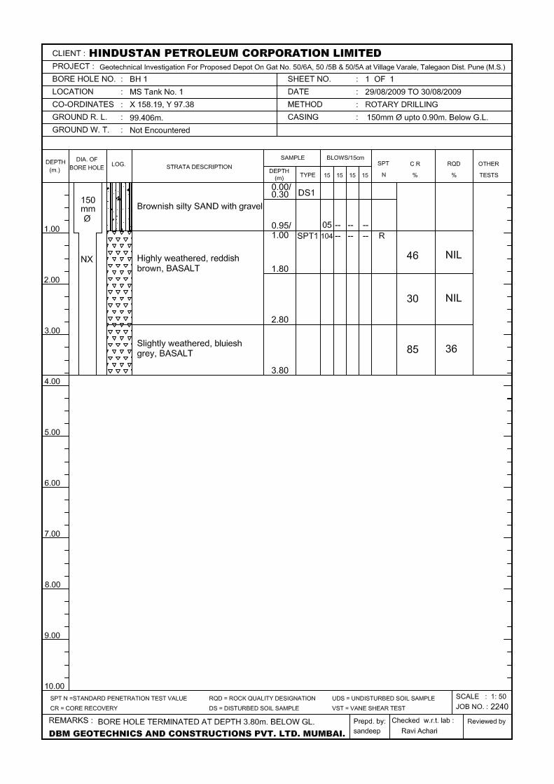
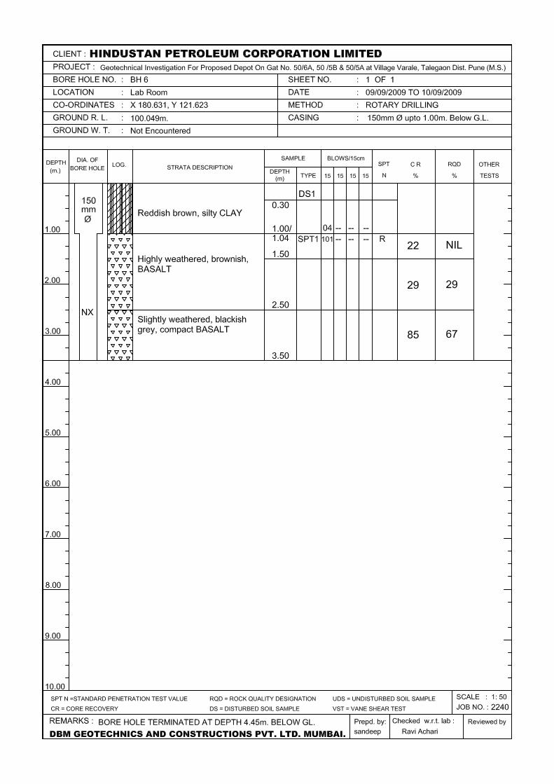
BH 1 MS Tank No. 1 158.19 97.38 99.406 3.80 BH 2 MS Tank No. 2 135.58 96.00 99.550 6.00 BH 3 HSD Tank No. 3 120.60 54.29 98.804 3.00 BH 4 HSD Tank No. 4 144.32 71.53 98.992 5.00 BH 5 Telecom Building 60.71 69.20 99.726 4.45 BH 6 Lab Room 180.63 121.62 100.049 3.50 BH 7 Office Room 197.320 122.184 99.789 3.00 BH 8 4 Bay T/T Gantry 187.335 109.325 99.248 3.70
TABLE A2 TRIAL PIT LOCATIONS AND GROUND LEVELS
TRIAL PIT NO.
STRUCTURE COORDINATES GROUND
LEVEL(m) TRIAL PIT DEPTH (m) X Y
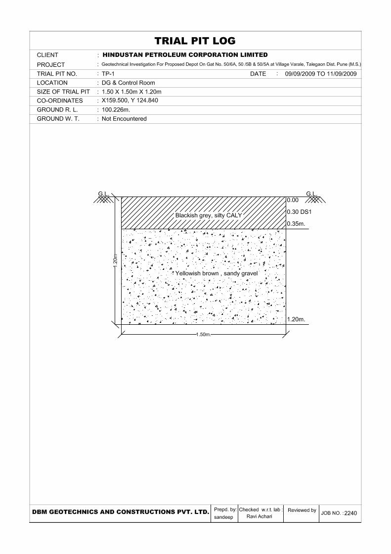
TP 1 DG/Control Room 159.500 124.840 100.226 1.20 TP 2 Pump House 130.000 105.312 100.284 1.05
TABLE A 3 ELECTRICAL RESISTIVITY TEST LOCATIONS AND GROUND LEVELS
ERT NO. STRUCTURE COORDINATES
GROUND LEVEL(m)
X Y
ERT 1 Between Tank No.1 & 2 146.887 96.667 98.500

3
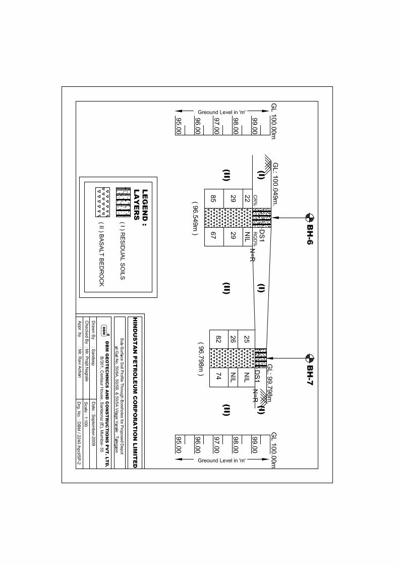
2.2 Subsurface Conditions
Subsurface profile at this site generally consists of residual soils underlain by Bedrock.
Encountered soil/rock layers are described below;
LAYER I: RESIDUAL SOILS
Residual soils, consisting mostly of brown clay or sandy gravel, were encountered in the
boreholes. The lower boundary of this layer was encountered at depths between of 1.0m
and 2.0m below ground surface.
LAYER II: BASALT BEDROCK
Reddish Brown Basalt bedrock was encountered at depths between 1.0m and 2.0m below
ground surface in the boreholes. The bedrock was highly weathered to sound. Core
Recoveries varied between 9% and 94%, while Rock Quality Designation (RQD) ranged
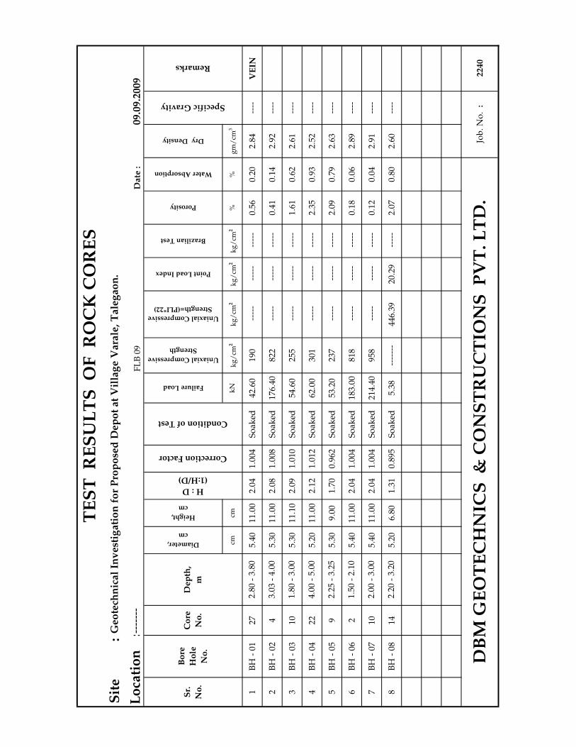
between 0% and 84%. Compressive strength of the rock core sample ranged between 190
kg/cm2 and 958 kg/cm2. The boreholes were terminated in this bedrock layer at depths
between 3.0m and 6.0m below ground surface.
4
2.3 Ground water Levels
Groundwater accumulation in boreholes was monitored during and after completion of
drilling activities. No groundwater was observed in any of the boreholes. Seasonal and
annual fluctuations in ground water levels can be expected.
3.0 FOUNDATION RECOMMENDATIONS
Weathered bedrock was encountered at depths between 1.0m and 2.0m below ground
surface. Spread/raft foundations for the proposed buildings and structures, supported on
this weathered bedrock, can be designed for a maximum net allowable bearing pressure of
40 t/m2.
Maximum settlement of foundations will be less than 10mm. A modulus of subgrade
reaction of 4,000 t/m3 can be utilized for design of foundations. Excavation sides should be
sloped at a maximum slope of 1:1 (horizontal:vertical) or flatter. Excavated soils are suitable
for use as footing backfill.
Proposed tanks exerting pressures of up to 22 t/m2 can be supported directly at or near the
existing ground surface. However, existing soils beneath tanks should be completely
removed for a depth of 1.0m and replaced with well compacted soils. Existing granular soils
5
(predominantly sand) at this site can be utilized as the replacement compacted fill.
Compacted fill should be placed in accordance with Section 3.3 of this report entitled
“Compacted Fill”.
3.1 Foundation Protection
A ‘mild’ Exposure Condition was assigned to this site. Therefore only following normal
precautions are recommended to protect subsurface concrete and reinforcement.
Type of Cement: OPC or PPC
Minimum Grade of Reinforced Concrete: M20
Minimum Cement Content for spread footings: 300 kg/m3
Maximum Water Cement Ratio: 0.50
Minimum Cover to Reinforcement: 50mm
3.2 Floor Slab or Pavements
The existing soils encountered at this site are capable of providing support for proposed floor
slabs and pavements. Areas to receive fill should be proof rolled with heavy equipment or
dump trucks to delineate zones of any loose or soft soils, which may require additional
removal and compaction. Based on borehole data, a minimum California Bearing Ratio

6
(CBR) value of 5 can be used for design of pavements installed at or near existing ground
surface.
3.3 Compacted Fill
Any existing surface vegetation should be removed from the area prior to any site grading.
Compacted fill beneath pavements/floor slabs or steel tanks or for site grading, should
consist of non-expansive soil, free of organics and rubble. As mentioned previously, a
minimum of 1m of existing soils should be removed beneath tanks and replaced with
compacted fill. On-site granular soils (sand) can be utilized as replacement compacted fill.
Compaction of granular soils to the recommended degree of compaction can generally be
attained with vibratory compaction equipment. Proper compaction of cohesive soils can be
achieved with pneumatic type compactors under optimum moisture conditions. Fill should
be placed in loose lifts of maximum thickness of 250mm and compacted to a minimum of 95
percent of its maximum dry density as determined by the Standard Proctor Test.
3.4 Electrical Resistivity Tests
One Electrical Resistivity test (ERT-1) were completed at this site. Results of the test are
enclosed in the Annexure. Soil resistivities were ranged between 18.378 ohm-m and 89.064
ohm-m.

7
4.0 FIELD EXPLORATION PROCEDURES
The sub-surface investigation was completed generally as per IS: 1892-1979. The field
investigation was carried out using a rotary machine. Casing was used to support sides of
borehole until sufficiently stiff strata was encountered. Standard Penetration Tests (i.e.
SPT) were carried out in soil in accordance with IS 2131-1981. Using this procedure, a 2”
outside diameter split-barrel sampler is driven into the soil by 63.5 kg. weight falling through
75 cm height. After an initial set of 15cm, the number of blows required to drive the sampler
an additional 30 cm, is known as the “penetration resistance” or “N value”.
When SPT refusal was obtained in hard strata, rock coring was done using diamond bit and
double tube core barrel to obtain rock samples. Percent Rock Core Recovery and Rock
Quality Designation (%RQD) were determined. % RQD = 100 x Sum of length of rock
pieces in cms, each having lengths greater than 10cms/Total length of core run.
Sincerely,
DBM GEOTECHNICS AND CONSTRUCTION PVT. LTD. __________________________________ Jaydeep Wagh B.E., M.S., P.E. (Geotechnical)
REFERENCES
1) Foundation Analysis and Design, J.E. Bowles, McGraw Hill Publication, 5
th Edition, 1996.
2) Canadian Foundation Engineering Manual. 3) Soil Mechanics in Engineering Practice, 2
nd Edition, Terzaghi K. and Peck R. B., John
Willey and Sons, 1967. 4) Foundation Design Manual, N. V. Nayak, 5
th Edition, 1996.
5) IS:6403-1981, Code of Practice for Design and Construction of Shallow Foundations on
Soils.
9
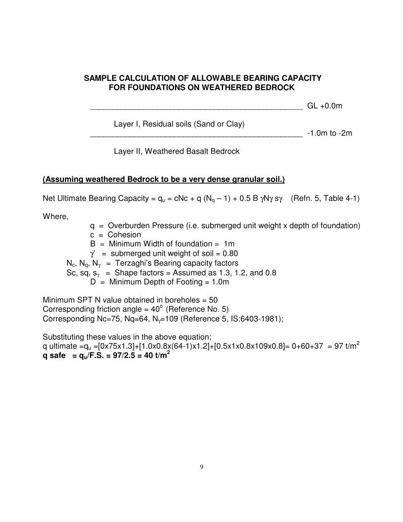
SAMPLE CALCULATION OF ALLOWABLE BEARING CAPACITY FOR FOUNDATIONS ON WEATHERED BEDROCK
________________________________________________ GL +0.0m Layer I, Residual soils (Sand or Clay) ________________________________________________ -1.0m to -2m Layer II, Weathered Basalt Bedrock (Assuming weathered Bedrock to be a very dense granular soil.)
Net Ultimate Bearing Capacity = qu = cNc + q (Nq – 1) + 0.5 B γNγ sγ (Refn. 5, Table 4-1) Where, q = Overburden Pressure (i.e. submerged unit weight x depth of foundation) c = Cohesion B = Minimum Width of foundation = 1m
γ’ = submerged unit weight of soil = 0.80
Nc, Nq, Nγ = Terzaghi’s Bearing capacity factors
Sc, sq, sγ = Shape factors = Assumed as 1.3, 1.2, and 0.8 D = Minimum Depth of Footing = 1.0m Minimum SPT N value obtained in boreholes = 50 Corresponding friction angle = 40
o (Reference No. 5)
Corresponding Nc=75, Nq=64, Nγ=109 (Reference 5, IS:6403-1981); Substituting these values in the above equation; q ultimate =qu =[0x75x1.3]+[1.0x0.8x(64-1)x1.2]+[0.5x1x0.8x109x0.8]= 0+60+37 = 97 t/m
2
q safe = qu/F.S. = 97/2.5 = 40 t/m2

10
CALCULATION OF SETTLEMENTS OF FOUNDATIONS (3M X 3M) EXERTING PRESSURE OF 40 T/M2:
From Reference No. 1:
Settlement = S q BE
mI Is
s f=−
0
21
'µ
Where, q0 = Footing Pressure = 40 t/m2 B’ = B/2 (Where B is the width of pressure distribution µ = Poisson’s ratio = 0.3 E = Modulus of Elasticity Is = Influence Factor (Obtained from Table 5-2, Reference No. 1) If = Depth Factor (Obtained from Figure 5-7, Reference No. 1)
m = 4 for center of footing
Very conservatively assuming weathered bedrock within the full influence zone of footings: E value for over-consolidated sand = 105(N)+4000 (Reference No. 1) Therefore, for a SPT N value of 50, E=9,250 t/m2
L’ = 3/2 =1.50, B’ = 3/2 = 1.5, H=6m, and D=1.0m Therefore, M=L/B=1; and N=H/B’=4 and D/B=0.33
Corresponding, Is = 0.43, Conservative If = 1.0 (From Table 5-2, Reference 1)
Settlement of Layer = S1 = 0.143.049250
3.015.140
2
xxxxx−
= 0.011m = 11mm
From IS8009: Due to Footing Rigidity Factor, Settlement = 0.8 x 11mm = 9mm Therefore, Total Settlement = 9mm


Date
:09.0
9.2
009
Bitum
en T
ank N
o.
1 &
2C
urr
en
t : 7
Am
p
X 1
46.8
877
Vo
ltag
e :
50 V
Y 9
6.6
773
98.5
00m
.
Wenners
Four
Pin
Equal P
robe S
pacin
g.
Field
Reading
R ( N - S )
Field
Reading
R ( NE - SW )
Field
Reading
R ( E - W )
Field
Reading
R ( SE - NW )
mo
hm
oh
mo
hm
oh
mo
hm
oh
mo
hm
oh
mo
hm
oh
m -
m
11
.00
.03
11
00
3.1
00
.02
61
00
2.6
00
.03
21
00
3.2
00
.02
81
00
2.8
02
.93
18
.37
8
22
.00
.02
71
00
2.7
00
.02
11
00
2.1
00
.02
61
00
2.6
00
.02
31
00
2.3
02
.43
30
.47
3
33
.00
.02
31
00
2.3
00
.01
91
00
1.9
00
.02
41
00
2.4
00
.02
10
02
.00
2.1
54
0.5
27
44
.00
.02
11
00
2.1
00
.01
71
00
1.7
00
.02
21
00
2.2
00
.01
81
00
1.8
01
.95
49
.00
9
55
.00
.01
91
00
1.9
00
.01
81
00
1.8
00
.02
01
00
2.0
00
.01
61
00
1.6
01
.83
57
.33
4
66
.00
.01
71
00
1.7
00
.01
61
00
1.6
00
.01
81
00
1.8
00
.01
81
00
1.8
01
.73
65
.03
1
77
.00
.01
61
00
1.6
00
.01
71
00
1.7
00
.01
91
00
1.9
00
.01
61
00
1.6
01
.70
74
.77
0
88
.00
.01
41
00
1.4
00
.01
51
00
1.5
00
.01
61
00
1.6
00
.01
31
00
1.3
01
.45
72
.88
5
99
.00
.01
61
00
1.6
00
.01
41
00
1.4
00
.01
71
00
1.7
00
.01
61
00
1.6
01
.58
89
.06
4
10
10
.00
.01
31
00
1.3
00
.01
21
00
1.2
00
.01
51
00
1.5
00
.01
41
00
1.4
01
.35
84
.82
3
Apparent Soil
Resistivity
ρρρρ = 2 ππππ a R
Dir
ecti
on
- S
E-N
W
Jo
b N
o.
:2
24
0D
BM
GE
OT
EC
HN
ICS
& C
ON
ST
RU
CT
ION
S P
VT
. L
TD
.
Range
Range
Range
Electrode
Spacing, a
Sr.
No
R (Average)
Dir
ecti
on
- E
- W
Lo
cati
on
:
Range
Dir
ecti
on
- N
- S
Dir
ecti
on
- N
E -
SWEL
EC
TR
ICA
L R
ES
IST
IVIT
Y T
ES
T
Red
uced
Level
:
Su
rvey M
eth
od
:
Pro
ject
:
Geo
tech
nic
al
Investi
gati
on
Fo
r P
rop
osed
Dep
ot
On
Gat
No
. 50/6
A,
50 /
5B
& 5
0/5
A a
t V
illa
ge V
ara
le,
Tale
gao
n D
ist.
Pu
ne
(M.S
.)E
RT
1
Co
ord
inate
:
Test
No
.
:
0.0
1.0
2.0
3.0
4.0
5.0
6.0
7.0
8.0
9.0
10
.0
11
.0
12
.0
02
04
06
08
01
00
Depth (m)
Ap
pa
ren
t S
oil R
es
isti
vit
y (
oh
m-m
)

----
-D
AT
E:
Wet Density
Dry Density
Gravel %
Sand %
Silt %
Clay %
Liquid %
Plastic %
Plasticity Index,
Ip %
Type
Cohesion Cu
kg/cm2
Degree φ
Comp. Index
Ccv (Lab)
Initial Void
Ratio
BH
- 0
10.
00 -
0.3
0D
S 1
---
-- -
----
---
--S
C8
4523
2442
2418
13 -
----
---
-- -
----
---
-- -
----
---
--2.
65
BH
- 0
20.
00 -
0.3
5D
S 1
---
-- -
----
---
--C
I5
3432
2948
2622
12 -
----
---
-- -
----
---
-- -
----
---
--2.
64
BH
- 0
30.
00 -
0.6
0D
S 1
---
-- -
----
---
--S
M21
52 -
----
---
-- -
----
---
-- -
----
---
-- -
----
---
-- -
----
---
--2.
66
BH
- 0
40.
00 -
0.5
0D
S 1
---
-- -
----
---
--C
H3
2434
3954
2727
14 -
----
---
-- -
----
---
-- -
----
---
--2.
63
BH
- 0
41.
00 -
1.4
5S
PT
1 -
----
---
-- -
----
GM
4840
---
-- -
----
---
-- -
----
---
-- -
----
---
-- -
----
---
-- -
----
---
--
CH
EM
:T
uu
:
Tri
ax
ial
Tes
t (
Un
con
soli
da
ted
Un
dra
ined
)S
P
:
Sw
elli
ng
Pre
ssu
re o
r S
wel
lin
g P
ote
nti
al
Tes
tA
ng
le o
f In
tern
al
Fri
ctio
n
CO
MP
:
Tcu
:
Tri
ax
ial
Tes
t (
Co
nso
lid
ate
d U
nd
rain
ed )
SP
T
:S
tan
da
rd P
enet
rati
on
Tes
t S
am
ple
Un
dra
ined
Co
hes
ion
DS
:T
cd
:T
ria
xia
l T
est
( C
on
soli
da
ted
Dra
ined
)U
DS
:
Un
dis
turb
ed S
oil
Sa
mp
leE
ffec
tiv
e A
ng
le o
f In
tern
al
Fri
ctio
n
K
:
NP
:N
on
Pla
stic
VL
:L
ab
ora
tory
Va
ne
Sh
ear
Tes
tE
ffec
tiv
e C
oh
esio
n
FS
I
:S
L
:
Sh
rik
ag
e L
imit
Tes
tU
C
:
Un
con
fin
ed C
om
pre
ssio
n T
est
Co
mb
ined
Sil
t +
Cla
y
Per
mea
bil
ity
Tes
t
Ch
emic
al
An
aly
sis
2240
Job
. N
o.
:
Fre
e S
wel
l T
est
Remarks
Ve
rica
l
Co
nso
lid
ati
on
12.0
9.20
09
Shrinkage Limit %
Tri
ax
ial
Te
st
C
on
sist
an
cy
Lim
its
Soil Classification (I.S)
Depth in m.
Sample Type
UD / D
SO
IL T
ES
T D
AT
A S
HE
ET
DB
M G
EO
TE
CH
NIC
S &
CO
NS
TR
UC
TIO
NS
PV
T. L
TD
.
Co
mp
act
ion
Tes
t
Dir
ect
Sh
ear
De
nsi
ty
gm
/ cm
3 M
ech
an
ica
l A
na
lysi
s
Lo
cati
on
:
Bore Hole No.
Natural Moisture
Content, w %
27 12
Specific Gravity
Pro
ject
:F
LB
04
Geo
tech
nic
al
Inv
est
igati
on
fo
r P
rop
ose
d D
ep
ot
at
Vil
lag
e V
ara
le,
Tale
gao
n.
Unconfined
Compression Test
Kg/cm2

Part
icle
%%
%%
mm
mm
mm
BH
- 0
10.
00 -
0.3
0S
C8
4523
24 -
----
---
-- -
----
---
-- -
----
4224
18D
S 1
BH
- 0
20.
00 -
0.3
5C
I5
3432
29 -
----
---
-- -
----
---
-- -
----
4826
22D
S 1
BH
- 0
30.
00 -
0.6
0S
M21
52 -
----
---
-- -
----
---
-- -
----
---
-- -
----
---
--D
S 1
BH
- 0
40.
00 -
0.5
0C
H3
2434
39 -
----
---
-- -
----
---
-- -
----
5427
27D
S 1
BH
- 0
41.
00 -
1.4
5G
M48
40 -
----
---
-- -
----
---
-- -
----
---
-- -
----
---
--S
PT
1Liquid
Limit, Wl
φφφφ10%
φφφφ30%
Co
eff.
of
Un
ifo
rmit
y,
Cu
= D
60 /
D1
0
Co
eff.
Of
Cu
rva
ture
Cc
D3
02/(
D6
0*D
10)
Gra
v
el
San
d
DBM GEOTECHNICS & CONSTRUCTIONS PVT. LTD.
Siz
e(m
m)
Dep
th i
n m
.
Plasticity
Index, Ip
Cla
y
Sil
t
φφφφ60%
Plastic
Limit, Wp
Bo
re
Ho
le
No
.
Sy
mb
o
l
Job No. :
Geotechnical Investigation for Proposed Depot at Village Varale, Talegaon.
Cla
ssif
i-
-cati
on
( IS
)
Remarks
Project :
2240
-----
GRAIN SIZE DISTRIBUTION CURVE
Location :
1227
0
10
20
30
40
50
60
70
80
90
10
0
0.0
00
10
.00
10
.01
0.1
11
0
PERCENTAGE FINER THAN
PA
RT
ICL
E S
IZE
( m
m )
GR
AV
EL
FC
SA
ND
CM
FS
ILT
CL
AY
80
.0
20
.0
4.7
5
2.0
0
0.4
25
7
5x1
0-3
2x1
0-3
FC
SA
ND
FCC

Part
icle
%%
%%
mm
mm
mm
BH
- 0
50.
00 -
0.4
0C
I2
3530
33 -
----
---
-- -
----
---
-- -
----
4927
22D
S 1
BH
- 0
60.
00 -
0.3
0S
M40
45 -
----
---
-- -
----
---
-- -
----
---
-- -
----
---
--D
S 1
BH
- 0
70.
00 -
0.2
0C
H5
2333
39 -
----
---
-- -
----
---
-- -
----
5628
28D
S 1
BH
- 0
80.
00 -
0.5
0G
M51
32 -
----
---
-- -
----
---
-- -
----
---
-- -
----
---
--D
S 1
17
-----
Remarks
Project :
GRAIN SIZE DISTRIBUTION CURVE
Location :
2240
Bo
re
Ho
le
No
.
Sy
mb
o
l
Job No. :
Geotechnical Investigation for Proposed Depot at Village Varale, Talegaon.
Cla
ssif
i-
-cati
on
( IS
)
Gra
v
el
San
d
DBM GEOTECHNICS & CONSTRUCTIONS PVT. LTD.
Siz
e(m
m)
Dep
th i
n m
.
Plasticity
Index, Ip
Cla
y
15
Sil
t
φφφφ60%
Plastic
Limit, Wp
Liquid
Limit, Wl
φφφφ10%
φφφφ30%
Co
eff.
of
Un
ifo
rmit
y,
Cu
= D
60 /
D1
0
Co
eff.
Of
Cu
rva
ture
Cc
D3
02/(
D6
0*D
10)
0
10
20
30
40
50
60
70
80
90
10
0
0.0
00
10
.00
10
.01
0.1
11
0
PERCENTAGE FINER THAN
PA
RT
ICL
E S
IZE
( m
m )
GR
AV
EL
FC
SA
ND
CM
FS
ILT
CL
AY
80
.0
20
.0
4.7
5
2.0
0
0.4
25
7
5x1
0-3
2x1
0-3
FC
SA
ND
FCC

----
-D
AT
E:
Wet Density
Dry Density
Gravel %
Sand %
Silt %
Clay %
Liquid %
Plastic %
Plasticity Index,
Ip %
Type
Cohesion Cu
kg/cm2
Degree φ
Comp. Index
Ccv (Lab)
Initial Void
Ratio
BH
- 0
50.
00 -
0.4
0D
S 1
---
-- -
----
---
--C
I2
3530
3349
2722
13 -
----
---
-- -
----
---
-- -
----
---
--2.
64
BH
- 0
60.
00 -
0.3
0D
S 1
---
-- -
----
---
--S
M40
45 -
----
---
-- -
----
----
---
-- -
----
---
-- -
----
---
-- -
----
2.66
BH
- 0
70.
00 -
0.2
0D
S 1
---
-- -
----
---
--C
H5
2333
3956
2828
14 -
----
---
-- -
----
---
-- -
----
---
--2.
63
BH
- 0
80.
00 -
0.5
0D
S 1
---
-- -
----
---
--G
M51
32 -
----
---
-- -
----
----
---
-- -
----
---
-- -
----
---
-- -
----
2.66
CH
EM
:T
uu
:
Tri
ax
ial
Tes
t (
Un
con
soli
da
ted
Un
dra
ined
)S
P
:
Sw
elli
ng
Pre
ssu
re o
r S
wel
lin
g P
ote
nti
al
Tes
tA
ng
le o
f In
tern
al
Fri
ctio
n
CO
MP
:
Tcu
:
Tri
ax
ial
Tes
t (
Co
nso
lid
ate
d U
nd
rain
ed )
SP
T
:S
tan
da
rd P
enet
rati
on
Tes
t S
am
ple
Un
dra
ined
Co
hes
ion
DS
:T
cd
:T
ria
xia
l T
est
( C
on
soli
da
ted
Dra
ined
)U
DS
:
Un
dis
turb
ed S
oil
Sa
mp
leE
ffec
tiv
e A
ng
le o
f In
tern
al
Fri
ctio
n
K
:
NP
:N
on
Pla
stic
VL
:L
ab
ora
tory
Va
ne
Sh
ear
Tes
tE
ffec
tiv
e C
oh
esio
n
FS
I
:S
L
:
Sh
rik
ag
e L
imit
Tes
tU
C
:
Un
con
fin
ed C
om
pre
ssio
n T
est
Co
mb
ined
Sil
t +
Cla
y
17
Shrinkage Limit %
Tri
ax
ial
Te
st
Natural Moisture
Content, w %
FL
B 0
4G
eo
tech
nic
al
Inv
est
igati
on
fo
r P
rop
ose
d D
ep
ot
at
Vil
lag
e V
ara
le,
Tale
gao
n.
Unconfined
Compression Test
Kg/cm2
Co
nsi
sta
ncy
Lim
its
Soil Classification (I.S)
Depth in m.
Sample Type
UD / D
SO
IL T
ES
T D
AT
A S
HE
ET
Pro
ject
:
DB
M G
EO
TE
CH
NIC
S &
CO
NS
TR
UC
TIO
NS
PV
T. L
TD
.
Co
mp
act
ion
Tes
t
Dir
ect
Sh
ear
De
nsi
ty
gm
/ cm
3 M
ech
an
ica
l A
na
lysi
s
2240
Job
. N
o.
:
Fre
e S
wel
l T
est
Remarks
Ve
rica
l
Co
nso
lid
ati
on
Per
mea
bil
ity
Tes
t
Ch
emic
al
An
aly
sis
Specific Gravity
15
Lo
cati
on
:
Bore Hole No.
16.0
9.20
09

----
-D
AT
E:
Gravel %
Sand %
Silt %
Clay %
Liquid %
Plastic %
Plasticity Index,
Ip %
Type
Cohesion Cu
kg/cm2
Degree φ
Comp. Index
Ccv (Lab)
Initial Void
Ratio
TP
-01
0.3
0D
S 1
1.6
02
0.4
0 -
----
CH
21
04
14
76
42
93
51
40
.55
---
-- -
----
---
-- -
----
---
-- -
----
2.6
2
TP
-02
0.5
0D
S 1
2.0
21
0.2
0 -
----
GP
93
3--
----
----
-- -
----
---
-- -
----
---
-- -
----
---
-- -
----
---
--2
.68
CH
EM
:T
uu
:
Tri
axia
l T
est
( U
nco
nso
lid
ated
Un
dra
ined
)S
P
:
Sw
elli
ng
Pre
ssu
re o
r S
wel
lin
g P
ote
nti
al T
est
An
gle
of
Inte
rnal
Fri
ctio
n
CO
MP
:
Tcu
:
Tri
axia
l T
est
( C
on
soli
dat
ed U
nd
rain
ed )
SP
T
:S
tan
dar
d P
enet
rati
on
Tes
t S
amp
leU
nd
rain
ed C
oh
esio
n
DS
:T
cd
:T
riax
ial
Tes
t (
Co
nso
lid
ated
Dra
ined
)U
DS
:
Un
dis
turb
ed S
oil
Sam
ple
Eff
ecti
ve
An
gle
of
Inte
rnal
Fri
ctio
n
K
:
NP
:N
on
Pla
stic
VL
:L
abo
rato
ry V
ane
Sh
ear
Tes
tE
ffec
tiv
e C
oh
esio
n
FS
I
:S
L
:
Sh
rik
age
Lim
it T
est
UC
:U
nco
nfi
ned
Co
mp
ress
ion
Tes
t C
om
bin
ed S
ilt
+ C
lay
FL
B 0
4G
eo
tech
nic
al
Inv
est
iga
tio
n f
or
Pro
po
sed
De
po
t a
t V
illa
ge
Va
rale
, Ta
leg
ao
n.
Unconfined
Compression Test
Kg/cm2
DB
M G
EO
TE
CH
NIC
S &
CO
NS
TR
UC
TIO
NS
PV
T.
LT
D.
Co
mp
acti
on
Tes
t
Dir
ect
Sh
ear
Mech
an
ical
An
aly
sis
Lo
cati
on
:
C
on
sist
an
cy
Lim
its
Soil Classification (I.S)
Depth in m.
Sample Type
UD / D
Pro
ject
:
22
40
Job
. No
. :
Fre
e S
wel
l T
est
Remarks
Veri
cal
Co
nso
lid
ati
on
Per
mea
bil
ity
Tes
t
Ch
emic
al
An
aly
sis
4
Natural Moisture
Content, w %
Specific Gravity
Shrinkage Limit %
16
.09
.20
09
Swelling Pressure
kg/cm2
Tri
axia
l T
est
Optimum Moisture
Content %
Maximum Dry
Density
SO
IL T
ES
T D
AT
A S
HE
ET
Bore Hole No.

Pa
rtic
le
%%
%%
mm
mm
mm
TP
-01
0.3
0C
H2
10
41
47
---
-- -
----
---
-- -
----
---
--6
42
93
5D
S 1
TP
-02
0.5
0G
P9
33
5.1
71
1.5
2.2
50
.84
----
----
----
DS
1
2240
Sy
mb
o
l
Job No. :
Geotechnical Investigation for Proposed Depot at Village Varale, Talegaon.
DBM GEOTECHNICS & CONSTRUCTIONS PVT. LTD.
Siz
e(m
m)
De
pth
in
m.
Plasticity
Index, Ip
Cla
y
Sil
t
φφφφ60%
Bo
re
Ho
le
No
.
Plastic
Limit, Wp
Remarks
-----
Gra
v
el
Sa
nd
Project :
Cla
ssif
i-
-ca
tio
n
( IS
)
GRAIN SIZE DISTRIBUTION CURVE
Location :
4
Liquid
Limit, Wl
φφφφ10%
φφφφ30%
Co
eff.
of
Un
ifo
rmit
y, C
u
= D
60 /
D10
Co
eff.
Of
Cu
rvat
ure
Cc
D3
02/(
D6
0*D
10)
0
10
20
30
40
50
60
70
80
90
100
0.0
00
10
.00
10
.01
0.1
11
0
PERCENTAGE FINER THAN
PA
RT
ICL
E S
IZE
( m
m )
GR
AV
EL
FC
SA
ND
CM
FS
ILT
CL
AY
80
.0
20
.0
4.7
5
2.0
0
0.4
25
7
5x1
0-3
2x10
-3
FC
SA
ND
FCC

Date : 16.09.09
Project :
Location : TP - 01
Depth : 0.30 Weight of Hammer : 4.89 kg
Reduced Level : ------ Height of Fall : 45 cm
Type of Test : Modified Proctor Test No. of Layers : 5
Observation Table
Rammer
Job. No. :
Chekd. By :
6
Dry Density
gm / cm3
4
27.80
1.600
1.49
Maximum Dry Density ( gm / cm3
) :
1
23.90
5
3
PROCTOR DENSITY TEST RESULTS
Geo. Investigation for Proposed Depot at Village Varale, Talegaon.
11.20
1.60
1.56
2 15.10
20.40
Proctor Test Apparatus
DBM GEOTECHNICS & CONSTRUCTIONS PVT. LTD. Md. Aarif
2240
1.53
Sr. No.Water
Content %
1.48
Optimum Moisture Content ( % ) : 20.40
v3 Pins to
Form Clutch
For Collar
Detachable
Base Plate
100
127Mould
180
Three Lugs
Brazed on
Collar
Hei
gh
t o
f F
all
v
1.46
1.48
1.50
1.52
1.54
1.56
1.58
1.60
1.62
10 12 14 16 18 20 22 24 26 28 30
Dry
Den
sity
( g
m /
cm
3)
Moisture Content ( % )

Date : 16.09.09
Project :
Location : TP - 02
Depth : 0.50 Weight of Hammer : 4.89 kg
Reduced Level : ------ Height of Fall : 45 cm
Type of Test : Modified Proctor Test No. of Layers : 5
Observation Table
Rammer
Job. No. :
Chekd. By :
Proctor Test Apparatus
DBM GEOTECHNICS & CONSTRUCTIONS PVT. LTD. Md. Aarif
2240
1.90
Sr. No.Water
Content %
1.80
Optimum Moisture Content ( % ) : 10.20
PROCTOR DENSITY TEST RESULTS
Geo. Investigation for Proposed Depot at Village Varale, Talegaon.
4.71
2.02
1.93
2 7.20
10.20
Dry Density
gm / cm3
4
14.30
2.020
1.82
Maximum Dry Density ( gm / cm3
) :
1
12.20
5
3
6
v3 Pins to
Form Clutch
For Collar
Detachable
Base Plate
100
127Mould
180
Three Lugs
Brazed on
Collar
Hei
gh
t o
f F
all
v
1.77
1.80
1.83
1.86
1.89
1.92
1.95
1.98
2.01
2.04
4 5 6 7 8 9 10 11 12 13 14 15 16
Dry
Den
sity
( g
m /
cm
3)
Moisture Content ( % )
-------
FL
B 0
9D
ate
:
Diameter,
cm
Height,
cm
Failure Load
Uniaxial Compressive
Strength
Uniaxial Compressive
Strength=(PLI*22)
Point Load Index
Brazilian Test
Porosity
Water Absorption
Dry Density
cmcm
kN
kg
/cm
2k
g/
cm2
kg
/cm
2k
g/
cm2
%%
gm
/cm
3
1B
H -
01
275.
4011
.00
2.04
1.00
4S
oak
ed42
.60
190
---
-- -
----
---
--0.
560.
202.
84--
--V
EIN
2B
H -
02
45.
3011
.00
2.08
1.00
8S
oak
ed17
6.40
822
---
-- -
----
---
--0.
410.
142.
92--
--
3B
H -
03
105.
3011
.10
2.09
1.01
0S
oak
ed54
.60
255
---
-- -
----
---
--1.
610.
622.
61--
--
4B
H -
04
225.
2011
.00
2.12
1.01
2S
oak
ed62
.00
301
---
-- -
----
---
--2.
350.
932.
52--
--
5B
H -
05
95.
309.
001.
700.
962
So
aked
53.2
023
7 -
----
---
-- -
----
2.09
0.79
2.63
----
6B
H -
06
25.
4011
.00
2.04
1.00
4S
oak
ed18
3.00
818
---
-- -
----
---
--0.
180.
062.
89--
--
7B
H -
07
105.
4011
.00
2.04
1.00
4S
oak
ed21
4.40
958
---
-- -
----
---
--0.
120.
042.
91--
--
8B
H -
08
145.
206.
801.
310.
895
So
aked
5.38
----
---
446.
3920
.29
---
--2.
070.
802.
60--
--
4.00
- 5
.00
2.25
- 3
.25
Job
. N
o.
:
2.20
- 3
.20
1.50
- 2
.10
2.00
- 3
.00
DB
M G
EO
TE
CH
NIC
S &
CO
NS
TR
UC
TIO
NS
PV
T. L
TD
.2240
1.80
- 3
.00
Sr.
No
.
Condition of Test
Specific Gravity
Remarks
2.80
- 3
.80
3.03
- 4
.00
Co
re
No
.
H : D
(1:H/D)
Correction Factor
Bo
re
Ho
le
No
.
Dep
th,
m
TE
ST
RE
SU
LT
S O
F R
OC
K C
OR
ES
Sit
e
:
09.0
9.2
009
Lo
cati
on
:G
eo
tech
nic
al
Inv
est
igati
on
fo
r P
rop
ose
d D
ep
ot
at
Vil
lag
e V
ara
le,
Tale
gao
n.

FL
B 1
0
SIT
E :
DA
TE
:1
6.0
9.2
00
9
SR
NO
.
BO
RE
HO
LE
NO
.
DE
PT
H
IN
ME
TE
RS
TY
PE
OF
SA
MP
LE
pH
EL
EC
TR
OM
ET
ER
ICA
LL
Y
SU
LP
HA
TE
AS
SO
3
%
CH
LO
RID
E
AS
Cl
%
RE
MA
RK
S
1B
H -
10
.30
DS
- 1
6.9
30
.00
80
.03
0
2B
H -
20
.35
DS
- 1
6.6
30
.00
60
.01
9
3B
H -
30
.60
DS
- 1
6.9
10
.00
70
.02
5
4B
H -
40
.40
DS
- 1
6.9
50
.00
90
.02
9
5B
H -
50
.40
DS
- 1
6.8
80
.00
70
.02
9
6B
H -
60
.30
DS
- 1
6.9
60
.00
80
.03
4
7B
H -
70
.20
DS
- 1
9.9
00
.00
60
.02
9
8B
H -
80
.50
DS
- 1
6.8
40
.00
60
.02
5
DB
M G
EO
TE
CH
NIC
S &
CO
NS
TR
UC
TIO
NS
PV
T.
LT
D
CH
EM
ICA
L T
ES
T R
ES
UL
T O
F S
OIL
SA
MP
LE
S.
Ge
ote
chn
ica
l In
ve
stig
ati
on
fo
r P
rop
ose
d D
ep
ot
at
Vil
lag
e V
ara
le,
Ta
leg
ao
n.
Job
No
.2
24
0