report of co~ittee on explosion. protection systems … of co~ittee on explosion. protection systems...
TRANSCRIPT

Report of Co~ i t tee on Explosion. Protection Systems
A. Richard Albrecht~ Chairman Dew Chemical Co.
(Rep. CHA)
John V. B i r tw is t le , Monsanto Co. Willi.am J. Bradford, Brookfield, CT Laurence G. Br i t ton, Union Carbide Corp. George P. Garland, Crown Fire Protection
Rep. FSSA Joseph P. G i l l i s , Fenwal Inc. '" Stanley S. Grossel', Hoffmann-LaRoche Inc. Randal D. Hamilton, BS&B Safety Systems Walter B. Howard, St. Lou'is, 140 George A. Krabbe, Automatic Suppression'Systems Inc.
Rep. NAFED. R. A. Mancini, Amoco Oil. Co.
Rep. API John Nagy, Library, PA Edward S. Naidus, APC Corporation
Rep. AAMA Robert W. Nelson, Industr ial Risk Insurers John A. Noronha, Eastman Kodak Co. Anthony Santos, Factory Mutual Research C o r p . " ' R. F. Schwab,'Allied Corp. " ~ C. E. Scott, Kemper Group
Rep. A.AI Ian Swift, Fike Technical Services Harry Verakis, Mine Safety & Health Admin. Robert C. Worthington, Central SprinklerCorp.
Rep NFSA (Vote Limited to NFPA 69) . ..
Alternates
Robert L. DeGood, Fike Metal Products Corp. (Alternate to I. Swift)
J. D. Dick, Kemper Group.. (Alternate to C. E. Scott)
David C. Kirby,. Union Carbide Corp. (Alternate to L. G. Br i t ton)
Edward D. Leedy, Industr ial Risk Insurers (Alternate to R.. W. Nelson)
Arnold L. Mundt, BS&B Safety Systems (A l ternate to R. O. Hamil ton),-
Gregory G. Noll,.Amerlcan Petroleum Ins t i tu te . (Alternate to R. A. Mancini) ~• .
Thomas'K. Palmer, Automatic Fire Protection Systems (Alternate to G. A. Krabbe)
Parker Peterson, Fenwal Inc. (Alterhate to J. P. G i l l i s )
Edwin Dale Weir, Ciba-Geigy Corp. (Alternate to R. Albrecht) "
Robert G. Zalosh, ,Factory Mutual Research Corp. (A l ternate to A. Santos~
This l i s t represents the membership'at t'he t ime the Committee was ba l lo ted oh the t ex t of t h i s ed i t i on . Since that t ime, changes in the membersh'ip may have occurred.
the Report of the Committee on Explosion Prot.ection Systems is presented fo r '~dop t ion .
This Report was prepared by ' the Technical Cemmitte~ on Explosion Protect ion Systems and proposes fo r adoption a complete rev is ion to NFPA 68-1978, Guide fo r Explosion Venting. NFPA 68-1978 is publ ished in . Volume B of the 1986 National Fire Ce~es and in separate pamphlet form.
This Repor't has been submitte~ t o l e t t e r b a l l o t of the Technical Committee on Explosion Protect ion Systems which consists of 20"vot ing members;,of whom 19 voted a f f i r m a t i v e l y , and 1 negat ive ly .
. Mr, Nagyls negat ive 'vo te is based on the f a c t tha t the Committee is c a l l i n g the document a guide whi!e i t is wr i t ten as a Code. He fee ls that Regulatory Agencies should be advised to use' caut ion in making th is guide mandatory. Mr. Nagy is also concerned about any possible l i a b i l i t y i f the user Follows the guide and s t i l l has an explosion. Another voiced concern is that there is no data demonstrating the spec i f i c inf luence of turbulence on de f l ag ra t i on pre~sur e and dP.
dt Add i t ion 'a l ly he fee ls that there is no discussion
concerning' the va r i a t i on of K with" increases in vessel volume.
4 '
37

• " : (Log # I ) 68- I - (Entire Doc.ument): Accept in Principle ~ : Edward S. Naidus, APC Corporation RECOMMENDATION: ( I ) Al l reguired explosion re l i e f vents an~ associated components shall be of an approved type. Approval by the o f f i c i a l having j u r i sd i c t i on . shall be based on acceptable performance tests and standards ( for the entire assembled device and not only unassembled components) by a qualif ied test!ng organization such as Fenwal Laboratories, Ashland, . Massachusetts, Factory Mutual Laboratories, Norwood,' Massachusetts, or others.
(2) Tests shall include both pressure and time measurements expressed as average maximum pressure (at the instant of ve'nt"release) in pounds/sq f t (Kg/sqm) and as average time (milliseconds) to release (from ignit ion time to release time). The integrated product of "maximum pressure" multiplied by'"release time" is called "impulse" and should range below lO percent of the estimated 'limpulse" load resistance of the building. (Example: most buildings of conventional steel and masonry block can resist an "impulse" of 100 Ib/sq f t for 0.5 seconds). The vent~ should open fu l l y at not over 30 Ib/sq f t in not over 50 milliseconds.
(3) "Unit vents shall not be used for access, and when in the closed"positlon shall not have fixed openings (to the out~ide) in the unit greater than.1 percent of the vent area.
(4) Unit vents mounted on a roof shall have provisions for restraining a 200 Ib person from fa l l ing through the vent in the nonactivated condition. "(5) Materials of construction shall be durable and
functional (without frequent inspection and maintenance) in the expected environment of weather, ~orrosion, temperature, ignit ion sources and mechanical loading as well as.a~y known special hazards. The releasable portions of the vent shall be tethered t o mlnlmlze " f ly ing object" hazards and shall not g ive ' rise to project i les or shards that'may Cause injury. SUBSTANTIATION: Standards'for explosion venting have been expressed in rat ios of vent area to building volume in NFPA standards"and various model code
, . " , ,
provlslons. However, detai ls as to explosion vent performance have not usually been stated and the approving o f f i c i a l has been forced to rely on general principles. In recent years, standards and test performance have been developed to the point where basic engineering information can now be furnished to architects, builders, engineers and code o f f i c i a l s . (See references.)
Ref: (1) Accidental Explosions - H. A. Streblow
Nasa Cr 134779 - June, 1975 (2) Factory Mutual System - Loss Prevention Data 7-76
August, 1976) p. 16 (3) Dust Explosions and Fires - K. N. Palmer -
Chapman & Hall - London (1973) I t is now known that damage to buildings or large
structures by internal pressure waves depends on a characteristic time response of the building. When the pressure wave moves more rapidly (most explosions) than the building can redistr ibute the energy of the pressure wave (the building is too r igid or not f lex ib le enough) then a portion or al l of the building collapses. The purpose of an explosion vent is to reduce the total energy on the "building bef%re the building reaches the force x time impulse that wi l l cause damage. The characterist ic time response decreases with increasing r ig id i t y but for conventional masonry, steel or timbered structures, the time constant wi l l range close to I /2 second. Therefore, venting must occur well below I /2 second af ter ignit ion to be of Value. Use of vents For uses other than primary emergency explosion re l i e f may cause excessive wear, damage or other performance impairment.
Current safety objectives for construction, maintenance or emergency personnel are met by providing a safety structure around or over the vent.
For specialized structures, such as ducts over 6 f t in diameter of 4 f t x 4 f t in area, elevator legs, conveyor throughways, etc. , unit vents should be placed on al l exter ior faces and the vents should extend the fu l l width of the structure. The vents should have a smallest dimension of 3 f t (I meter) and a dimension rat io of not over 2.
Structures with L/D greater than 3 require higher vent ratios than near-cubical buildings. (Example: Elevator legs should have vents no less than 20 f t on center.) COMMITTEE ACTION: Accept in Principle. COMMITTEE COMMENT: The Committee believes that the Submitter's concerns are adequately addressed by this complete revision of NFPA 68.
'(Log #4) 68- 2 - (2-2.1.9'): Accept in Principle ~ : Robert D. Coffee, Eastman Kodak Company RECOMMENDATION: Revise as follows start ing with l ine 17:
"In order for moisture to prevent ignit ion of a dust by common sources, the mois'ture content must be normally around 13-14 percent or greater. Moisture contents of this magnitude frequently render the dust so damp that dust clouds can not be formed." SUBSTANTIATION: Published data of U.S. Bureau of Mines (34) (Figure 2-2.1.9(b)), Eckhoff (see comment on 2-2.1.5), and unpublished data of Eastman Kodak Co. show inab i l i t y to obtain dust explosions at moisture contents above 14 percent for many materials. qOMMITTEE A~TION: Accept in Principle. COMMITTEE COMMENT: Se'ction 2-8 of the revised draft addresses this point.
(Log #5) 68- 3 - (A-3): Reject ~ : Thomas E. Frank, Tacoma, WA RECOMMENDATION: In paragraph beginning "The use of vent ducts can lead to substantially increased pressure." delete or revise the last two sentences, beginning with "When duct lengths exceed about 10 f t
I I
SUBSTANTIATION: I believe these two sentences are misleading, when taken out of context. The lO f t vent duct length may have produced the pressure increases in the cited example (Ref. 22), but surely this'doesn't apply to al l cases ( i . e . , d i f ferent vent sizes). I believe this effect is a function of L/D not just L, as well as numerous other variables (e.g., pressure rat io across the vent at the moment of release, densities and specific heat values of gas/dust mixtures, e tc . ) . To state a "c r i t i ca l length" of lO f t is a drastic oversimplif ication of the problem, and is in error when taken out of context. The statement regarding lO f t vent ducts should be put in proper context or deleted.
Also the statement concerning transit ion to detonation in very long ducts is primarily a phenomenon of gaseous mixtures. To my knowledge, the only case of detonation observed'for dusts was in small scale tubes using aluminum dust (Class ST-3) suspensions enriched with pure oxygen. This certainly does not represent most industrial conditions and the statement should perhaps be qualified in regards to dust explosions. qOMMITTEE ACTION: Reject. COMMITTEE COMMENT: Chapter 8 of this draft presents al ternat ive guidelines that the Committee feels provide a greater degree of safety.
(Log #6) 68- 4 - (A-5): Reject ~_VBMITTER: Thomas E. Frank, Tacoma, WA RECOMMENDATION: Revise to read as follows:
A-5 Venting of Gas or Dust Combustion Inside Air Conveying Ducts. Most of the cases of flammable gas or dust mixtures inside ducts of the a i r venti lat ion type occur at i n i t i a l internal pressure of nearly atmospheric. The venting of gas combustion in such ducts is discussed in Appendix C. Since the gas/air test mixtures used in Appendix C have cubic law constants (K o) similar to Class ST-2 dusts (Kst), the guidelines presented in Appendix C can be considered applicable to most Class ST-I and ST-2 dusts.
38

SUBSTANTIATION: No guidelines are suggested for combustible dusts in elongated.vessels or ducts (L/D >_ 5). Many such si tuat ions ,~re encountered in " industry (e.g., plywood and particleboard sander dust col lect ion systems, f lash tube dryers' e t c . i . The guidel ines' in Appendix C have been us'ed for wood'dust conveying systems with•numerous explosions successfully vented. -From Figure'2-2.1.8 in this standard, Hethane/alr'
under turbulent condit ionsgenerated a maximu~ rate-of-pressure rise'~of 12;500 p:~i/~ec in a ' l cu' f t closed vessel. This gives a cubic'law constant of:
KG : 12,500 psi x ( I ) ~/~ = 12,500 psi - f t ' = 259 atm-m sec sec • sec
C6mpare w i t h wood dus t ( C l a s s S t - ; : ) :
Kst = 230 atm-m ( f r o m Tab le A - 3 i b ) in t h i s s t a n d a r d ) . sec
Appendix C shou ld y i e l d s a t i s f a c t o r y v e n t i n g ' g u i d e l i n e s f o r Cla~s ST-1 and 'ST-2 d u s t s . : COMMITTEE ACTION: :'Reject. .• = " , '" COMMITTEE COMMENT: Chapter 8 of t.his dra f t presents a l ternat ive guidelines that the'Committee feels 'provide a greater degree of safety...
(Log #3) "' 68- S - (A-5-1 (New)): Reject . . ' " ~ : Thomas E• Frank, Tacoma, WA " " RECOMMENDATION: Add new subsection as follows:
A-5-I The fol lowing graph may be'substituted for Table C-2 in Appendix C to ~btain the spacing b~t~ween
• consecutive vents: ' ' ' ' "'"
5 . . . . . , ,X=2 " K=I . data from Table C-2 / / " "
3 . . ' . / . ". ~ D = d u c t d i a m e t e r
2 - ' ' ' " / / / ~ L=dista'nce ' ~ / ~ " between '
• / . ~ ~ - . ~ - - _ ~ consecutive 1 - ' / ' ~ ' ~ / / ' ' • vents
0 4 8 12. 16 20 -.24 • 28 32. . 36 L= ,ft ' . . •
F i gu re A - 5 - I Space 'and S i z e ' o f Ven ts A long Ducf.s Containing Moving Gas or Ai r Mixtures•
NOTE: 'The above curves are plots of the fol lowing equations:
D•= (L1) 2 : + 25 L~. (K=I), " ~' 426
D = (L~.) z + 35 L~ (K-2") '" . 234 '
These equations were derived b'y force-f i ' t t i 'ng 2nd order equations of the form
D = a(L~) z + b(L~) + c
to the data"in Table C-2.! This~ermi'ts an "orderly, logical extrapolation to large~ duct diamet'ers, which is necessary i f the guidelines are to be usable ' for industr ia l-s ized equipment. SUBSTANTIATION: The guidelines in Table C-2 do not present any data fo r duct diameters larger than 2 f t 6 in. Many ,industri'al size, low pressure pneumatic conveying systems use ducts up•'to 5 f t diameter, or even larger• Guidelines are needed for these larger s y s t e m s . '
• • .,.
Since the data in Table C-2 is only approximate (as evidenced by the discontinuity at l f t 6 in. duct diameters), a. smooth curve forceTf i t ted to the tabular data should~yield equally acceptable results. Then, the curve'can be extPapolated to larger'diameters, providing usable guidelines. Several wood dust explosions have been successfully vented in ducts 3 to 4 f t in diameter using these guidelines. Though this is'no't ~6nclusive evidence, i t does tend to indicate general acceptabi l i ty for use as ~ guide, which is better than no guidelines at a l l . COMMITTEE ACTION: Reject• COMMITTEE COMMENT: The Committee feels that the guidelines in Chapter 8, which are applicable to both large and small diameter ducts, provide a more comprehensive design basis. '
..
(Log #7) 68- 6 - (A-5-2 (New)): Reject • SUBMITTER: Thomas E. Frank, Tacoma, WA RECOMMENDATION: Add new subsection as follows:
A-5-2 Where L/D is less than 6, the nomographs in this Appendix may be used in l ieu of the design data by Simmonds and Cubbage (Reference 71) mentioned in Appendix C. This, too, should give a s l ight overestimation of the necessary vent area. SUBSTANTIATION: ".The nomographs are inferred as being applicable on ly : fo r vessels with L/D'< 5• Tile work by Simmonds and Cubba~e (1961) wa~ done on vessels with L/D ~ 3 as noted in Appendix C. This leads t o an overestimation of vent area as L/D approaches 6.
I t would seem the.homographs would gi've at least as accurate an estimation of vent area, i f not,more so. They, too, give an overestimation as L/D. approaches 6. Since the work by Simmonds and Cubbage is only referenced in. Appendi~ A and not presented i n a usable form, i t is n~cessary to obtai'n a •reprint of the paper to get any usable guidelines, The homographs should give an equally acceptable guide and are already presented for use. qQMMITTEE AqTION: Reject. COMMITTEE COMMENT: Chapter 8 of this dra f t presents a l te rnat ive guidelines that the Committee feels provide a greater degree Of safeEy.
(Log #2) 68 ~ 7 -(Appendix C, Vent Closures and Figure 'C- l ) : Accept in Principle SUBMITTER: Gerald E. L ingenfel ter , American Insurance Association REqOMMENDATIQN: Revise paragraph to read: ."Diaphragm-vent or panel closures of metal f o i l , f l ex ib le or f ranoib le heat resistant 'types of p last ic sheets, or varlous other commerclally avai lable rupture
"discs can be used.' Prefe#ence should be given to the use of a noncombustible material ' to protect equipment against f i res external to the'equipment. Figure C-I shows a method of constructing a panel closure." , Rev ise Figure C-I to 'delete reference to asbestos "
millboard (use only "Panel") and revise t i t l e of Figure to "Panel. Closure".
"SUBSTANTIATION: Stat is t ics produced by the'Department of.H~alth, Education and Welfare (Health and Human Resources) indicate the potential losses to people exposed ~ndirectly to' asbestos in the ins ta l la t !on , modificati'on or repair of 'asbestos produc~s are vast• These exposures to part ic les of asbestos produce several diseases related to lung ailments• Ailments are being caused by the mere breathing of~ai r ' contaminated by asbestos f ibers below 5-I0 micrometers.
Further, "use of such materials has already been deleted from NFPA No. 211 5or' these reasons, and'we are not aware of anyone who is presentl~ commercially producing this product• COMMITTEE ACTION: Accept in ~r in~iple. COMMITTEE COMMENT: The Committee bel ieves that the Submitter's concerns are adequately addressed by this complete ~evision of NFPA 68.
39

68- 8 - (Entire Document): Accept SUBMITTER: Technical Committee on Explosion Protection Systems RECOMMENDATIONi Completely revise the 1978 edition of NFPA 68, Guide for Explosion Venting, as shown in the following text . SUBSTANTIATION: I . The revision brings NFPA 68 up-to-date with the current state of the art .
2. The revision takes into account much new data that has been published since the last edit ion. COMMITTEE ACTION: Accept~
NFPA 68
Guide f o r Ven t i ng of ' D e f l a g r a t l o n s
1987 Edition
NOTICE: Information on referenced publications can be found in Appendix E.
Chapter 1 General
l - l Scope.
l - l . l This'Guide applies to the design and use of devices and systems that wi l l vent the combustion gases and pressures resulting from a deflagration within an enclosure so that structural and mechanical damage is minimized. The enclosure may be a room, a building, a piece of equipment, or any other type of enclosure. The deflagration may result from the ignit ion of a combustible gas, mist, or dust.
l - l . 2 This Guide does not apply to detonations, bulk autoignition of gases, or unconfined deflagrations, such as open-air or vapor cloud explosions.
l - l . 3 This Guide does not apply to devices that are designed to protect storage vessels against excess internal pressure due to external Fire .exposure or to exposure from other heat sources. (See NFPA 30, Flammable and Combustible Liquids Code.)
l - l . 4 This Guide does not apply to emergency vents for runaway exothermic reactions.
I - I . 5 This Guide does not apply to pressure re l i e f devices on equipment such as oi l- insulated transformers. I t also does not apply to pressure re l i e f devices on tanks, pressure vessels, or domestic (residential) appliances.
I-2 Purpose. The purpose of this Guide is to provide the user with c r i te r ia for venting of deflagrations. I t is important to note that venting wi l l not prevent a deflagration; venting wi l l minimize the destructive effects of a deflagration.
1-3 Definit ions. F o r the purpose of this Guide, the following terms have the mean!ngs given below.
Burning Velocity. The velocity at which a flame front propagates relat ive to the unburned material in a direction perpendicular to the flame front. Burning velocity varies with mixture composition, temperature, pressure, and the turbulence in the v ic in i ty of the flame front.
Combustible. Capable of undergoing combustion.
Combustion. A chemical process of oxidation that occurs at a rate fast enough to produce heat and usually l igh t , either as glow or flames.
Deflagration. Propagation of a combustion zone at a velocity which is less than the speed of sound in the unreacted medium.
Detonation. Propagation of a combustion zone at a velocity which is greater than the speed of sound in the unreacted medium.
Dust . Any f i n e l y d l v i d e d ~ s o l i d , 420 microns o r l e ss in d iameter ( i . e . , ma te r i a l pass ing th rough a US No. 40 Standard S i e v e ) .
Exp ]os ion . B u r s t i n g or r u p t u r e o f an enc losu re o r a c o n t a i n e r due to the development o f i n t e r n a l p ressu re by a deflagration. ~ •
Flame Speed. The speed of a flame front relat ive to a fixed reference point. Flame speed is dependent on turbulence and the equipment geometry and is not primarily a property of the fuel.
Flammable Limits. The minimum and maximum concentrations of a combustible material, in a homogeneous mixture with a gaseous oxidizer, that w i l l propagate a flame.
Flammable Range. The range of concentrations lying between the lower and upper flammable l imi ts .
Flashpoint, The minimum temperature at which a l iquid gives o f f vapor in suf f ic ient concentration to form an ign i t ib le mixture with a i r near the surface of the l iquid, as specified by test.
Fog. See def ini t ion of mist.
Fundamental Burning Velocity. The burning velocity of a laminar (nonturbulent) flame under stated conditions of composition, temperature, and pressure of the unburnedgas.
Gas. The state of matter characterized by complete molecular mobi l i tx and indefinite expansion. Used synonymously witff the term "vapor."
Hybrid Mixture. A mixture of a combustible gas with either a combustible dust or a combustible mist.
Minimum Ignit ion Energy. The mlnimumamount of thermal energy released at a point in a combustible mixture that w i l l cause indef ini te flame propagation away from that point, under specified test conditions. The lowest value of the minimum ignit ion energy is found at a certain optimum mixture. I t is this value (at this optimum mixture) that is usually quoted as the minimum ignit ion energy.
Mist. A dispersion of re lat ively fine l iquid droplets in a gaseous medium. •
Optimum Mixture. A specific mixture of fuel and oxidant that yields the most rapid combustion 'in terms of a specific measured quantity or that has the lowest value of the minimum ignit ion energy or that produces the maximum deflagration pressure. The optimum mixture may not be the same for each combustion property measured.
Oxidant. Any gaseous material that can react with a fuel (ei ther gas, dust, or mist) to produce combustion. Oxygen in a i r is the most common oxidant.
Rate of Pressure Rise (dP/dt). The rate of increase in pressure over the time interval required for that increase to occur. The ~ rate of pressure rise is computed from the slope of the steepest part of the pressure versus time curve during deflagration in a closed vessel. (See Appendix A, Guidelines for Measuring Deflagration Indices of Gases and Dusts.)
Stoichiometric Mixture. A mixture of a combustible material and an oxidant in which the oxidant concentration is just suf f ic fent to cgmpletely oxidize the fuel.
Vapor. See def in i t ion of Gas.
Vent Ratio. The rat io of the free area .of the vent to the volume of the enclosure protected by the vent.
I-4 Conversion Factors. The following conversion factors, to three signif icant figures, wi l l be useful in understanding the data presented in this Guide:
40

Area
Volume
l m
1 in. I f t "
1 micron
I m z I yd z I in. z
l l i t e r l f t s 1 m s
I gal (U.S.)
P r ~ ' 1 atmosphere
I psi 1Newton/m 2 1 bar
1 kilogram/cm 2 1 kilogram/m s
~ l Joule l Btu l Joule
Vent Ratio I f t z / f t 3 1 m2/m 3
K~ and Ks_t Conversion Factors
l bar-meter s e c
l ps i - foo t s e c
Concentration I oz. A v o i r . / f t 3
. , ~ ,
3.28 f t 39.4 in.
1 . 0 9 yd 2.54 cm '"
30.5 cm 1.00 x ID -6 m
10.8 f t z 0.836 m 2 6.45 cm z
• 61.0 in. a 7.48 U.S. gal
35.3 f t 3 264 U.S. gal • 3.78 l i t e r s "
231 in. 3 , 0.134 f t 3
760 m i l l i m e t e r s Mercury (mm Hg) 101 k i l oPasca l s (kPa)
14.7 psi 1.01 bars 6 . 8 9 kPa 1.00 Pascal
100 kPA 14.5 psi 0.987 atmosphere
14.2 psi 0.205 I b / f t z (psf)
1.00 Watt-second 1055 Joules
0.738 foot-pounds
3.28 m2/m 3 0.305 f t z / f t 3
47.6 os i - foo t sec
O.Q21 bar -mete r sec
I 0 0 0 g/m 3
I-5 Symbols. For the purpose of th is Guide, the fo l lowing symbols have the meaninos given below:
A - Area, m 2 or f t 2 or in. 2
As - ' I n t e rna l Surface Area of Enclosure, f t 2 or m 2
Av - Vent Area, m 2 or f t z
C - Constants in Correlat ion Equations for Figures 7- I (d ) , 7 - I (e ) , and 7-1( f ) . (See 7 - I . I . 2 ) or Constant in Venting Equation in Chapter 4.
Cg - Concentration of Gas in Mixture, percent by volume
dP/dt - Rate of Pressure Rise, ba~/sec or psi/sec
Fr - Reaction Force, Ib"
K G - Deflagrat ion Index "for Gases, bar-m/sec
Kr - Reaction Force Constant, Ib
Kst - Deflagrat ion Index fo r Dusts, bar-m/sec
L. - Linear Dimension of Enclosure, m or f~ (n = 1,2,3)
L/D - Length to diameter ra t i o , dimensionless
41
LFL
P
P
P m a x
Pred,
Pstat
AP
S.
Sf
St
tF
UFL
V
- Lower. Flammable Limit, percent by volume
- Perimeter of Duct Cross Section, m or f t
- Pressure, bar (gage) or pslg
- Maximum Allowable Overpressure OR Maximum Pressure Developed, bar (gage) or psig
- Reduced Pressure ( i . e . , the maximum pressure ac tua l ly developed during a
vented def lagra t ion) , bar (gage) or psig
- Vent Ciosure Release Pressure, bar (gage) or ps ig
- Pressure D i f f e r e n t i a l , bar o r psi
- Fundamental Burning V e l o c i t y , cm/sec
- Flame Speed, cm/sec
- T r a n s l a t i o n a l Flame V e l o c i t y , cm/sec
- Dura t ion o f pressure pu lse , sec
- Upper Flammable L i m i t , percent by volume
- Volume, m 3 or f t 3
N O T E : A l l pressures are gage pressure unless o the rw i se s p e c i f i e d .

Chapter 2 Fundamentals o f Oe f l ag ra t i on
2-1 P re requ i s i t es . The f o l l o w i n g are necessary f o r a d e f l a g r a t i o n to occur:
- f u e l , in the proper concen t ra t ion ; - an ox idan t , in s u f f i c i e n t quan t i t y to suppor(
the combustion; - an i g n i t i o n source s t rong enough to i n i t i a t e
combustion.
These f a c t o r s are discussed i n d i v i d u a l l y in the f o l l o w i n g sec t ions .
2 - 2 Fuel. The fue l invo lved in a d e f l a g r a t i o n may be a combust ible gas (o r vapor ) , a mis t o f a combust ible l i q u i d , a combust ib le dust , or some combination of these. The most common combinat ion o f two fue l s is tha t o f a combust ible gas and a combust ible dust , ca l led a "hybr id m ix tu re . "
2-2.1 Fuel Concent ra t ion.
2 - 2 . t . 1 Gaseous f u e l s have a lower f l ammab i l i t y l i m i t (LFL) and an upper f l ammab i l i t y l i m i t (UFL). Between these l i m i t s , i g n i t i o n is poss ib le and combustion w i l l take place. The optimum concent ra t ion usua l l y occurs at s l i g h t l y r i c h e r than the s t o i c h i o m e t r i c mix ture .
2 -2 .1 .2 Combustible dusts a lso have a lower flammability l imi t , often referred to as the "minimum explosive concentration." For many dusts, this concentration is about 20 g/m 3. Although this concentration can be experimentally determined, i ts practical value is somewhat limited because of the tendency for dust to fa l l out of suspension and sett le on surfaces. However, such deposits can be thrown into suspension, thereby forming a dust cloud having an ign i t ib le concentration. Therefore, the "minimum explosive concentration" can be used to determine the amount of such "stat ic" dust that may be allowed to safely accumulate.
.b
" 6 ;00
medxm volue M
Figure 2-2(a) E f f ec t o f average p a r t i c l e d iameter o f dusts on the maximum pressure and the maximum ra te of pressure r i s e developed by a d e f l a g r a t i o n in a I m 3 vesse l . (Reference 3)
6oo
.~ ,o {mJ] dust in _hybrid mixtures • HQnsa yellow M < 20 prn
500 ~lJJ x) ~ : ~lulose MM'-1251Jrn27pm ~ " . PVC M v - 20pm
K~ ~ , PVC M -125:~n 0 propQne lurbu~ent
4O(
~ 130 " "
C.
o j ' 1 v 2 ~ " - - - ~ I ~ VOI'I
1oo l e l
propane content
I r I I 40 80 120 160 200
Average Particle Oiameter. Microns
Figure 2-2(b) E f fec t o f average p a r t i c l e d iameter o f a t yp i ca l a g r i c u ] t u r a l dust on the minimum i g n i t i o n energy. (Unpub]ished data, cour tesy o f US Hine Safety and Heal th Adm in i s t r a t i on . )
Figure 2-2(c) Lowest minimum i g n i t i o n energy of hybr id mix tures versus propane content . (Reference 3)
4 2

W - |
. a ~ •
l ll"
•0
• . , PVC. dust c:~r',centt'~.w~n ,
~ m ' ~ " ~ d b ~ ' l :
3 ~1~ °1.
o . , ~ , B~ m~]
PVC dust c ~
~ . Figure 2-2(d Explosion data for Poiyvinyl Chlorlde/methane/air m~xtures (l m 3 vessel; chemical detonator with an ignit ion energy of 10,000 Joule).. (Referenc~ 4)
) I 4 5 6 [;~Vol|
,.. , propane content in air
dus,t in hyt:~id mixlures
0 l-iocISC )"~ilOw M . 20Liqq O cellulose M - 2~ " 0 PE M - (~0 .. 7 ;~C M - 20 ,.
i [ p,.,c M -12S 7 5 0 b a r / s ] ~ " (> C,-o;~Pe :urtxJ,ent
o. E soo~ . . f ~ - , ~ . . \ " 6 - = ~.
X ~ • ", \ "'J ' \ \
06 ~ 2 ~ ~ ' 4 ' s ' 6 i"va,!
p r o p a n e c o n t e n l i n a i r
Figure 2-2(e) Explosion data for dust/propane/air mixtures (l m 3 vessel: pyrotechnic igni ter with an ignit ion energy of lO,O00 Joule). (Reference.4).
A "maximum explosive concentration" exists but is d i f f i c u l t to evaluate because of problems in achieving adequate dispersion of the dustduring testing. Just as with gases, there exists an optimum concentration which yields the maximum rate of pressure rise during combustion.
Experiments show that a combustible dust cloud containing small particles (nomine~lly less than 420 microns) may deflagrate. The maximum rate of pressure rise and the maximum pressure developed both increase as part ic le size is decreased. The maximum rate of pressure rise is more sensitive to part ic le size, and th~ sensi t iv i ty can be most pronounced for part ic le sizes~below, about 50 microns. The sensi t iv i ty of . maximum pressure developed is most pronounced for the. l a rge rpa r t i c l e sizes in the size range of. 200 - 420 microns. Minimum ignit ion energy is.extremely sensitive to part ic le size. (Reference l) See Figures 2-2(a) and 2-2(b) for i l lus t ra t ions of these effects.
r*
I t should be noted that the average part ic le diameter is often reduced as a result of. attr i t ion~during material :handling and process!ng, and that certain process operations may cause separation of f ine part icles from coarse part icles. This results in the formation of a "zone" of part icles which has a smaller average part ic le diameter than the bulk of the material and which is no longer protected by the di lut ion ef fect of a suf f ic ient concentration of coarse part icles.
2-2.1.3 'A mist of combustible liq'uid droplets can also deflagrate. This may happen not Only at i n i t i a l " temperatures above the flash point, but also at any temperature below the flash point. In the extreme case, a cloud of frozen drople.ts may .defl agrate in the sam~ manner as a dust cloud.
The lower flammable l im i t (LFL) for dispersed l iquid hydrocarbon mists varies from about 50 mg/ l i ter to about lO mg/ l i ter as the representative droplet diameter increases from about lO to lO0 microns. F i f ty mg/ l i ter is roughly equal to the LFL for combustible gases in a i r at room temperature.
Ease of ignit ion of l iquid mists is related principal ly to the representative droplet diameter. The minimum ignit ion energy (MIE) increases in proportion to the cube of droplet diameter. (Reference 2) The MIE is reduced dramatically as droplet diameter is reduced.
Foams of combustible liquids burn readiiy and, as a source of finely-dispersed mist, they may exhibit a low MIE. Oxygen is mote soluble than nitrogen in most combustible liquids and i f a foam is produced by a degassing process the oxidant concentration may be enriched.
2-2.2 Hybrid Mixtures. ..
2-2.2.1 A mixture of a combustible gas and a combustible dust in an oxidant is referred to as a "hybrid mixture." The presence of the gas may have some effect on'the combustion characteristics of the dust. This influence may be considerable and may occur even though the gas is below, i ts lower flammable l im i t and the dust is below i ts minimum explosive concentration. For example, small amounts of combustible gas may lower the minimum ignlt ion energy of a dust cloud,• as. i l lustrated in Figure 2-2(c). The maximum rate of pressure rise during a deflagration may increase considerably, as shown in Figure 2-2(d), and the maximum pressure attained during the deflagration may also increase, as shown in Figure 2-3(e), although this lat ter , ef fect is less pronounced.
43

The minimum explosive concentration of the dust may be reduced and combination formulae have been suggested by both Bartknecht and Field to estimate this lower concentration (References 5 and 6). Dusts which have low Kse values seem to be more sensitive to the presence of a combustible gas. Careful evaluation of the ignit ion and deflagration characteristics of these mixtures is required; specific testing is strongly recommended, since a hybrid mixture may require more vent area than would be required by either component alone.
2-2.2.2 Situations where hybrid mixtures may occur in industrial processes include: f luidized bed dryers, in which combustible dusts wet with solvent are dried in a warm a i r stream, desorption of combustible solvent and monomer vapors from polymers, and coal pulverizing operations.
In many instances the evolution of the gas may be completely unexpected or may be very slow. I t has been shown that the introduction of a combustible gas into a cloud of dust which would normally be a minimal explosion hazard can result in a vigorous combustion of the hybrid mixture. An example of this phenomenon is the combustion of unplasticized polyvinyl chloride dust in an air/methane atmosphere.
2-3 Oxidant.
The oxidant in a deflagration is normally the oxygen in a i r . Oxygen concentrations greater than 21 percent tend to intensify the combustion reaction and increase the probabil i ty of transit ion to detonation. Conversely, concentrations less than 21 percent tend to decrease the rate of reaction. There is for most fuels a l imi t ing oxygen concentration below which combustion wi l l not occur. (See NFPA 69, Standard on Explosion Prevention Systems.) Also, other oxidants, such as the halogens, may have to be considered.
2-4 Burning Velocity and Flame Speed.
The flame speed is the local velocity of a freely propagating flame relat ive to a fixed point. I t is the sum of the burning velocity and the translational velocity of the flame front. This is expressed by the equation:
Sf = Su + St
Sf = flame speed, cm/sec;
Su = burning velocity, cm/sec;
St = translational veloclty, cm/sec.
The burning velocity is the velocity at which a plane reaction front moves into the unburned mixture'as i t chemically transforms the fuel and oxidant into combustion products. I t is only a fraction of the flame speed. The translational velocity is the sum of the velocity of the flame front caused by the volume expansion of the combustion products due to the increase in temperature and any increase in the number of moles and any flow velocity due to motion of the gas mixture prior to ignit ion. The burning veloc i ty .of the flame front can be calculated from the fundamental burning velocity, which is reported at standardized conditions of temperature, pressure, and composition of unburned gas.
2-5 Ignit ion Source.
2-5.1 Both the maximum pressure and the maximum rate of pressure rise developed during a deflagration in vessels much smaller than l m 3 increase as the energy of the ignit ion source increases. In larger vessels these increases only occur with powerful sources of igni t ion, such as j e t flames. Thus, the energy released by a point source of ignit ion in a re lat ive ly large vessel wi l l have l i t t l e effect on the course of the deflagration. This is because turbulence is induced in the flame front by the deflagration and this turbulence wi l l outweigh any effects of the ignit ion s o u r c e .
2-5.2 Ignit ion at the geometric center of an enclosure wi l l usually result in the most destructive effects. Of course, the energy of the ignit ion source must be above some minimum value. Values of these minimum ignit ion energies have been reported for gases and for dust clouds (References 7 through 13). Usually minimum ignit ion energies of gases are much lower than those of dust clouds. However, somerecent work has been reported which indicates that dust clouds can be ignited by sources releasing much less energy than has been previously reported (Reference 14).
2-5.3 Ignit ion can result from external energy sources such as an electr ical arc, a flame, a mechanically-produced spark (impact or f r i c t i on ) , or a hot surface. Ignit ion can also result from slow exothermic reactions which may produce spontaneous heating. Simultaneous multiple ignit ion sources may produce turbulence in the fuel/oxidant mixture that w i l l ' i n tens i f y deflagration. An ignit ion source may travel from one zone to another; e.g., a mechanical spark may be transported from a grinding mill to a dust col lector via ductwork. Similarly, a flame produced by an ignit ion source in one enclosure may i t s e l f become a much larger ignit ion source i f i t propagates to another enclosure.
2-6 I n i t i a l Temperature and Pressure. Any change in the i n i t i a l (absolute) pressure of the fuel/oxidant mixture at a given in i t i a l temperature, w i l l produce a proportionate change in the maximum pressure developed by a deflagration of the mixture in a closed vessel. Conversely, any change in the i n i t i a l (absolute) temperature at a given i n i t i a l pressure wi l l produce an inverse change in the maximum pressure attained. (See Figure 2-6.) However, an increase in temperature usually results in an increase in the maximum rate of pressure rise.
600
5017--
400m
~ 300B E :Z
2 0 0 - -
100- -
0 0.O4
Po ~ . ,
Po = 15 psia
7¢•* F 3 4 2 ° F 1~3" F I '
0.08 0.12 0.16 0.20 1
Reciprocal of Initial Temperature, °R x 10 -2
Figure 2-6 Effect of i n i t i a l temperature on 'the maximum pressure developed in a closed vessel for deflagrations of 9.9 percent methane/air mixtures at several i n i t i a l pressures. (Reference 15)
44
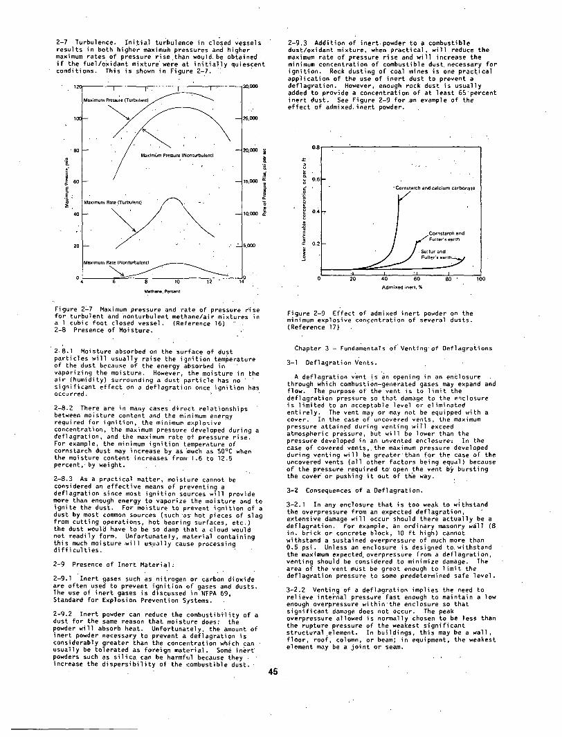
2-7 Turbulence. I n i t i a l turbulence in closed Vessels results in both higher maximum pressures and higher maximum rates of pressure rise than would, be obtained i f the fuel/oxidant mixture • were at i n i t i a l l y quiescent conditions. This is shown in Figure 2-7. i
12(]
10G
' 8 0
ioo E
4 0
20
I I ' . I I . Maximum pressure ( T u r b u l e n t ) ~ ' " - - ~
" Maximum Rate ( T u r b u l e n t ) ~ . ~ j . . . , ""
6 " 8 10 12 " 14
-" 3 0 , 0 ~
5,000
ZO,O00
•p= ._="
15,000 m
5,000
M e t h a n e , Percent
Figure 2~7 Maximum pressure and rate of pressure Fise for turbulent and nonturbulent methane/air mixtures in a I cubic foot closed vessel. (Reference 16) '" 2-8 Presence of Moisture.
2 -8 .1 Moisture absorbed on the surface of dust particles wi l l usually raise the ignit ion temperature of the dust because of the energy ,~bsorbed in vaporizing the moisture. However, the moisture in the a i r (humidity) surrounding a dust part ic le has no signif icant ef fect on a deflagration once ignit ion has occurred.
2-8.2 There are in many cases direct relationships between moisture content and the m~nimum energy required for ignit ion, the minimum explosive concentration, the maximum pressure developed during a deflagration, and the maximum rate of pressure rise. For example, the minimum ignit ion temperature of cornstarch dust may increase by as "much as SO°C when the moisture content increases from'It6 to 12.S percent,-by weight.
2-8.3 As a practical matter, moisture cannot be considered an effect ive means of preventing a deflagration since most ignit ion sources wi l l provide more than enough energy to vaporize the moisture and to ignite the dust. For moisture to prevent ignit ion of a dust by most common sources (such "as' hot pieces of slag from cutting operations, hot bearing surfaces, etc.) the dust wouIB have to be so damp that a cloud would not readily form. Unfortunately, material containing this much moisture w i l l usually cause processing d i f f i cu l t i es .
2-9 Presence of Inert Material;
2-9.1 •Inert gases such as nitrogen or carbon dioxide are often used to prevent ignit ion of gases and dusts. The use of inert" gases is discussed in NFPA 69, Standard for Explosion Prevention Systems.
2-9.2 Inert powder can reduce the ,:ombustibi~lity of a dust for the same reason that moisture does: the powder wi l l absorb heat. Unfortunately, the amount of inert powder necessary to prevent a deflagration is considerably greater than the concentration which can usually be tolerated as foreign material. Some inert" powders such as s i l i ca can be harmful because they. increase the d ispers ib i l i t y of the combustible d u s t .
45
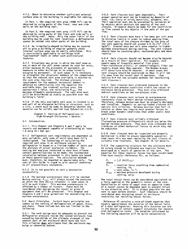
2-9.3 Addition of inert powder to a combustible dust/oxidant mixture, when practical, wi l l reduce the maximum rate of pressure rise and wi l l increase the minimum concentration of combustible dust necessary for igni t ion. Rock dusting of coal mines is one practical application of the use of inert dust to prevent a deflagration. However, enough rock dust is usually added to provide a concentration of at least 65"percent inert dust. See Figure 2-9 for an example of the ef fect of admixed, inert }owder.
0 . 8
.Z 0.6
¢ ' o
~ o.~ e
E
~- 0 . 2
- Cornstarch and calcium carbonate /
-I 0 20 100
Cornstarch arid
~# F u l l e r ~ .
I .... 'I I 40 60 80 ' Admixed inert, %
F i g u r e 2-9 Effect oF admixed inert powder on the minimum explosive concentration of several dusts. (Reference 17)
Chapter 3 - Fundamentals of' Venting of Deflagrations
3-i Deflagration Vents.
A deflagration vent is an opening in an enclosure through which combustion-generated gases may expand and flow. The purpose of the vent is to l im i t the deflagration pressure so that damage to the enclosure is limited to an acceptable level or eliminated ent i re ly. The vent may or may not be equipped with a cover. In the case of uncovered vents, the maximum pressure attained during venting wi l l exceed atmospheric pressure, but wi l l be lower than the pressure developed in an unrented enclosure: In the case of covered vents,.the maximum pressure developed during venting wi l l be greater than for the case of the uncovered vents (al l other Factors being equal) because of the pressure required to' open the vent .by bursting the cove~ or pushing i t out of the way.
3-2 Consequences of a Deflagration.
3-2.1 In any enclosure that is too weak to withstand the overpressure from an expected deflagration, extensive damage wi l l occur should there actually be a deflagration. For example, an ordinary masonry wi l l (8 in. brick or concrete block, lO f t high) cannot withstand a sustained overpressure of much more than 0.5 psi. Unless an enclosure is designed to. withstand the maximum expected overpressure from a deflagration, venting should be considered .to minimize damage. The area of the vent must be great enough to l im i t the deflagration pressure to some predetermined safe level.
3-2.2 Venting of a deflagration implies the need to relieve internal pressure fast enough to maintain a low enough overpressure within' the enclosure so that signif icant damage does not occur. The peak overpressure allowed is normally chosen to be less than the rupture pressure of the weakest signif icant structural.element. In buildings, this may be a wall , f loor , roof, column, or beam; in equipment, the weakest element may be a jo in t or seam.

Few data are available on the actual forces experienced by'the structural elements of an enclosure during a deflagration. Therefore, designs must be based on the.type of enclosure (vessel, equipment, room, building), i ts material of construEtion, i ts resistance to mechanical shock, the effects of vents (including consequent thrust forces), and the level and duration of overpressure. In practice, the vent design should be based on withstanding the maximum overpressure attained during venting of the deflagration. I f no venting is provided, the (maximum) overpressures developed during a deflagration wi l l typical ly be between 8 and 12 times the i n i t i a l absolute pressure, assuming complete combustion. In many cases i t ~s impractical and economically prohibitive to construct an enclosure that wi l l withstand or contain such pressures. In some cases, however, i t is possible to design for containment of a deflagration. (See NFPA 69, Standard for Explosion Prevention Systems.) I f adequate venting can be provided, the enclosure need not be constructed so robustly.
3-3 Maximum Rate of Pressure Rise and Maximum Pressure.
3-3.1 The rate of pressure rise is an important parameter in the venting of a deflagration; i t determines the time available for products of combustion" to escape from the enclosure and for pressure to dissipate. A rapid rate of rise means that only a short period of time is available for successful venting. Conversely, a slower rate of rise permits the venting to proceed more slowly, yet st i . l l be effect ive. In terms of required vent area, the more rapid the rate of r ise, the greater the area needed for venting to be effect ive, al l other factors being equal.
3-3.2 The ef fect of a deflagration depends on the maximum pressure attained, the maximum rate of pressure rise, and the duration of the peak overpressure. The total impulse imparted to the enclosure ( i . e . , the integral of the pressure vs. time curve) is reduced as the rat io of vent area to enclosure volume increases. (See Figure 3-3.) However, total impulse is not a useful design basis. The stress developed on the enclosure should be calculated on the bas~s of the stat ic force that is equivalent to the dynamic force developed at the'peak pressure reached during venting.
120 1,20C
101) 1,0~
80 ~ 80C
60 ~ 6~ E
40 ~ 4~
2O 2O0
0
I I --I I Du~ Concentration = 0.500 oz per cu h
_ ~~_ : :i
_Maximum Rate
2 3 4 5 I Ratio of Relief Area to Volume, .~ ft per 1QO.cu ft
12.000
1o.ooo
5,0~ i
E
~,000 •
Figure 3=3 Variation o'f pressures, rates, and impulses with vent ratios in magnesium deflagrations in a vented vessel. (Reference 18)
3-4 Vent Variables.
46
3-4.1 Vent Size and Shape. The maximum pressure developed in a vented enclosure decreases as the available vent area increases. I f the enclosure is re la t ive ly small and symmetrica]~ one large vent may be just as effect ive as several small vents of equal combined area. As an enclosure increases in size, this probably ceases to be true. Rectangular ~ents are almost as effect ive a~ square or circular vents of equal area; thus, vent shape has minimal ef fect on the successful application of venting.
3-4.2 Vent Type. Open or unrestricted vents are the most ef fect ive in relieving deflagration overpressures. Vents covered with a diaphragm, rupture disc, swinging or hinged cover, or other type of cover present iner t ia and a mechanical attachment that must be overcome. Such vents are inherently less ef fect ive. Chapter g describes various types of vents and vent closures.
3-4.3 Iner t ia of Vent Closure. The free area' of a vent does not become fu l ly effect ive in relieving ~he deflagration pressure unti l the vent closure moves completely out of the way of the vent opening. Until this occurs, the closure obstructs the combustion gases issuing from the vent. The closure has mass and this mass represents iner t ia that must be overcome by the force of the deflagration. Some f i n i t e period of time is needed For the combustion gases to push the closure completely out of the way.
Since the acceleration of the closure is inversely proportional to i ts mass, the greater the mass of the closure, the longer the closure takes to completely clear the vent opening for a given vent opening pressure. Conversely, closures of low mass move away from the vent opening more quickly and venting is more ef fect ive.
Experience has shown that the iner t ia of the vent closure is usually not signif icant i f the closure weighs less than 2.5 Ib per sq f t of free vent area.
3-4.4 Vent Operation. Vents must function dependably. Closures must not be hindered by deposits of snow, ice , or debris; neither must they be hindered by buildup.of deposits on their inside surfaces. Adequate, clear space must be maintained'on both sides of the vent to enable operation without rest r ic t ion and without impeding the free flow of vented gases..
3-5 Basic Recommendations for.Venting."Since venting of deflagrations is a complex subject of. many variables on which information is l imited, the following provides only general guidelines. ."
3-5.1 Venting is usually required in buildings, rooms, or equipment that contain an operation or process that may release combustible material in amounts suf f ic ient to create an ign i t ib le mixture with a i r or other available oxidant.
3-5.2 'The required vent area wi l l depend on the strength of the enclosure, the maximum rate of pressure rise, and maximum pressure developed for the fuel/oxidant mixture in question, and the design of the vent i t s e l f , including the presence'or absence of a closure device. Empirical methods are.presented in la ter chapters to determine the required vent area.
J
3-5.3 Vents should be evenly dlstr ibuted'over.the surface area of the enclosure to the greatest extent pract ical .
3-5.4 The gases vented from an enclosure during a deflagration must be directed to a safe locati'on to avoid injury to personnel and to minimize property damage. I t may be necessary" to insta l l guardrails immediately in front of vent panels in building walls and around vent panels in roofs to prevent personnel from fa l l ing against or through the panels. Suitable warning signs should also be posted. I t may also be necessary to provide restraining devices to keep vent panels or closures from becoming missile hazards. "An alternative means of protection is to provide a missile barr ier close enough to the vent to intercept any . missiles, but far enough from the vent so as not to impede i ts operation.

3-5.4.1 When a deflagration is vented, a-tongu:e of , flame o f ' b r i e f duration issues from'the~vent. I f the
fuel is a dust, this tongue of flame wi l l usually contain-some unburned dust, along with:'tl~e gaseous products of combustion. This is.because the amount of dust.present i n i t l a l l y is,usual'ly.greater than that which the oxidant in the container can burn.'~ This unburned dust w.ill be igni-ted as. i t flows out..the vent and can produce a large, f i rebal l that :w i l l extend not
,~ , oqly outward and upward, but .also downward from the vent. .This has been • shown-in, numerous tests.conducted with fu l l -scale equipment. , ,' ,
3-5.5 I'f vents a re ' f i t ted with closure devices, 'they should be designed so that they do not allow the development of a vacuum in the enclosure af ter heated
. , . ,
gases have cooled.
3-5.6 In'terconn'ections between separate pieces of equi'pment, should be avoided. ,,Where such interqonne, ct..ions.are necessary, flashback prevention devices should be considered to, prevent propagation of " the deflagration from one piece of equipment through the interconnection to other equipment. Such devices may be mechanical or chemical in operation.. •
3-5.? Str~uctural damage, can:also be minimized by locat ing vented equipment e i.ther ou'tslde buildings or in ,isolated areas. • ..
3-5.8 ,Ducts used to direct.vented gases from the vent to th.e, outside, of a building must be strong enough to withstand the maximum expected deflagrat-ion overpressure and must be able "to withstand, the maximum antici,pated temperature.during v,_~nting. Ducts should be. as short as possible',and should preferably not have any bends.. : ' . . .. ,- .
3'-5.9 Wind may cause a~vent to ~}perate falsely or may hinder~its operat.ion. Vent,desi!)n must anticipate the
.problems cr, eated by prevailing wind pat terns.
3-5.10 .Situations may occur in ~;hich i t is not possible to provide adequate def'iagration venting as described in Chapters 4 through ;~ of this Guide. This is not .iust il~ication for providing no venting at a l l . I t is suggested that the "maximum practical" amount of venting be provided, since some venting wi l l reduce the resulting damage to a limited deqree. In addition, consideration should be given to other pFotectlon and prevention methods..,(~See NFPA 69, Standard for .. Explosion Prevention ,Systems.) , ~ .
3-5.11 .,Reaction'forces result in 9 from venting should also be considered in the design of .the equi.pment and their supports. (See Subsection 5-2.9.)
Chapter 4 -'Venting of Defl.agrations . • in Low-Strength Enclosures
4-I Introduction.
4-1.1 Tl~is,Chapte'r is applicable to the~design of deflagration vents for low-strength enclosures capable of withstanding not more than 1.5 pslg (0.I bar ga.), such as rooms, bui:Idings, and cer taln.,equipment , e n.closures. • > -.
4'-i.2 The pooper design, of def]agrati,on vents depends on maoy .variables, only some of which have been . investigated in depth. The simpl,~st techniques use one or more empirical factors which ,allow, a simplified expression for vent area to.be adjusted so as to envelop availabl ~ data.. These data are the result .of anal'yses,of actual explosion i.ncidents and exper.imental tests. •
4-1.3 • Tests add analyses conducted to date have allowed certain generalizations to be.made. The calculationT techniques presented in - th is Guide are based on these generalizations, l 'he techniques must, " therefore, be recognized as 'approximate only. The user o f t h i s Gulde. i.s urged to give special" attention to. al l precaut.ionary statements. , . , . ,~ . , ' -
47
4-2 General . .. ~.
4-2'.1 The reason f o r p rov id ing d e f l a g r a t i o n ven t i ng f o r an enc losure is to min imize o r e l i m i n a t e s t r u c t u r a l damage to the enc losure i t s e l f and to reduce the p . r obab i l i t y o f both damage t o - o t h e r : s t r u c t u r e s and injury to personnel.
4-2.2 Most enclosures of.the type addressed by. this Chapter cannot be subjected to.high internal : overpressures without serious damage. Adequate venting can minimize the damage from a deflagration.,'However, the venting must be sufficient" to prevent the maximum pressure developed within the enclosure from exceeding the "breaking point" of the weakest structural element, which may be a wall, the f loor , the roof, a column, or a beam.
4-2.3 Care must be taken to ensure that the weakest structural element ,is recognized. All structural elements must be considered.- walls, windows, doors, f loors, ceilings, roofs, and structural supports'.' For example, i t must be recognized that f loors and roofs are usually not designed for much structural loading from beneath. Furthermore, the structural analysis must be based on the actual design and the existing condition of the enclosure.
4-3 Calculating the Vent Area.
4-3.1 Numerous methods have been proposed for " : ' calculating the vent area for an enclosure (References 19 through 23). Some venting models (References 24 and 25) have used the surface area of the enclosure as a basis for determining vent area. Analysis of available data (References 26 through 41) shows,that such methods overcome certain deficiencies of previous methods of calculating vent area. The recommended venting equation is as follows:
• . " . , ,
A~ = C A s
where Av = vent area ( f t 2 or m 2) C = venting equation constant (See Table
4-3) A s = internal surface area of enclosure" "
( f t 2 or m 2) P = maximum internal overpressure whlch can
be wi,thstood by the weake'st structural , , element (psi or kPa.)
4-3.2 Applicable Dimensions. The form of the venting equation is such that there are no dimensional constraintsc(such as a maximum length~to-dlameter
,'rat.i.o) ~ . that the vent area is no~' applied solely to one end of an'elongated enclosure. Fo~' elongated enclosures, the vent area should be applied as evenly as possible with respect to the longest dimension. I f the available vent area is restr icted to .one end of an elongated enclosure,~ for example the top of a s i lo or ' the end wall of a building, the rat io of length-to-diametem sho'uld not exceed 3. (For larger ratios of.length-to-diamete~ or higher,allowable ove~pressures, see Chapters'6 through 8.) "For cross-sections other than'clrcular or square, the effect ive diameter can be taken as the hydraul.ic diameter. The-hydraulic diameter is given by 4A/p,
,.where A is the cross-sectional'area,andp is the ' ,perimeter of~the cross-section. Therefore, i f the vent area is restricted to one end of an elongated .. enclosure, the venting equation is constrained-as follows:
L3 ~ 12 A/p ('.ft or m) . '
where L3 = longest dimenslon'of the enclosure
" ' ( f t or m ) ' . ' • -.~.,A = cross~sectional area ( f t 2 or m 2) •
. . . . p = perimeter of cross-section ( f t ' o r m)

I f the vent area is restr icted to one end of an elongated enclosure containing a highly-turbulent gas mixture, the rat io of length-to-diameter should not exceed 2, or:
L3 < 8 A/p ( f t or m)
Where the above constraints on L3 are violated, investigate alternate methods in Chapters 6 through 8 ~ r possible solutions.
I t should also be noted that these constraints apply only to the use of the recommended fuel characteristics constants given in Table 4-3.
4-3.3 Venting Equation Constant. The value of C in the venting equation serves two purposes: i t characterizes the fuel and i t clears the dimensional units. Also, two sets of C values have been derived so that the venting equation can be used with either English or SI units. Table 4~3 gives some recommended values of C.
Table 4-3
FU~I
Fuel Characteristic Constant for Venting Equation
C. (osia) I /z C(kPa. aa} I /z
Anhydrous Ammonia* 0.05 0.13
Methane 0.13 0.34
A1iphatic gases 0.16 0.42 (excluding methane) or gases with fun- damental burning velocity less than 1.3 times that of propane
St-1 dusts 0.08 0.21
St-2 dusts 0.14 0.37
St-3 dusts* 0.25 0.66
*Estimated
4-3.3.1 The values of C in Table 4-3 were determined by enveloping the available data. I f suitable large scale tests are conducted for a specific application, an alternate value of C may be used.
4-3.3.2 The available database includes References 26 through 41. Most data are for al iphatic gases. I t is believed that l iquid mists can be treated as al iphatic gases provided that the fundamental burning velocity of the vapor is less than 1.3 times that of propane. No recommendations can presently be given for fast-burning gases such as hydrogen, certain alkenes, alkynes, dienes and epoxides. This is because the recommended method allows for i n i t i a l turbulence and turbulence-generatlng internals and no venting data have been generated to address such conditions for fast-burning gases. Expert opinion should be sought in such cases. Unusually high rates of combustion (including detonation) have been observed in actual practice during turbulent hydrogen combustion; as conditions become severe, combustion rates may approach those of detonation for other fast-burning fuels. In addition, as rates of pressure'rise increase, the inert ia of vent closures becomes more c r i t i ca l (see Subsection 9-3.3). Even i f detonation does not occur, i t may be impossible to successfully vent fast deflagrations in some cases.
4-4 Calculation of Internal Surface Area. The enclosure is defined by the structural elements that are capable of withstanding the expected overpressure. The surface area of any equipment within the enclosure is excluded. Non-structural part i t ions which cannot withstand the expected overpressure (e.g., suspended ceilings) are not considered to be part of the enclosure's internal surface area, As. The internal surface area, As, in the venting equation, includes
48
roof or ce i l i ngs , wa l ls , and f l o o r and may be based on simple geometric figures. Thus, surface corrugations are neglected. Minor deviations from the simplest shape (parallelepiped, prism, cone, etc.) are also neglected. Regular geometrical deviations such as "saw-toothed" roofs may be "averaged" by adding the contributed volume to that of the major structure and calculating A s for the basic geometry of the major structure. However, while the surface area of equipment and contained structures should be neglected, the internal surface area of any a'djoinlng rooms must be included and the vent area distributed as symmetrically and evenly as possible in proportion to the contribution of each volume to As.
4-5 Enclosure Strength.
4-5.1 The term P in the equation is defined as the "maximum internal overpressure which can be resisted by the weakest structural element." This term was or ig ina l ly derived from an or i f i ce equation which uses the pressure' d i f ferent ia l across the o r i f i ce . Since one side of the vent is'always assumed to be atmospheric, the gage pressure within the enclosure can be used.
4-5.2 Theoretically, the force exerted on an enclosure by an internal deflagratlon is dynamic. However, recent work by Howard an d Karabinis (Reference 26) indicates that the enclosure may be assumed to respond as i f the peak deflagration pressure is applied as a stat ic. loading, provided some inelast ic deformation (but not catastrophic fai lure) can be accepted. Therefore, i f a structural member must not be permanently damaged or deformed by the deflagration i t must be designed to withstand the maximum internal overpressure, P, without catastrophic fa i lure.
4-5.3 In designing an enclosure to prevent catastrophic fa i lure while s t i l l allowing some. inelast ic deformation, the'normal dead and l ive loads should not be relied upon to provide adequate restra int . For example, wallsshould be fastened along top and bottom edges, as well as at a l l corners.
4-5.4 In al l cases, except as noted in Subsection 4-5.5, the maximum allowable design stress should not exceed two-thlrds of the ultimate strength.
4-5.5 Ductile design practices should be used. For materi'als subject to b r i t t l e fai lure, 'such as cast iron, special reinforcing should be considered. I f such reinforcing is not used, the maximum allowable design stress should not exceed 25 percent of the ultimate strength.
4-5.6 In al l cases, the strength of the enclosure should exceed the vent re l ie f pressure by at least 0.35 psi. (50 psf or 2.4 kPa)
4-6 Vent Design.
4-6.1 Where inclement weather, environmental contamination, or loss of material, is not a consideration, open vents may be used and are recommended. In most cases, however, vents wi l l be covered by some type of lightweight closure or panel. The panel must be designed, constructe d , instal led, and maintained so that i t wi l l readily release and move out of the path of the combustion gases. The panel must also not become a missile hazard when i t operates.
4-6.2 The total weight of the panel assembly, including any insulation and permanently-mounted hardware, should be as low as pract ical , but in no case should i t exceed 2.5 I b / f t 2. The purpose of this l imi ta t ion is to keep the inert ia of the assembly as low as possible so that the vent opens as rapidly as possible.
4-6.3 The material of construction of the panel should besui table for the environment towhich i t wi l l be exposed. B r i t t l e materials wi l l fragment, producing potent ial ly lethal missiles. Some panels, because of the i r configuration, may travel some distance from the enclosure. Each instal lat ion must be evaluated to determine the extent of the hazard to personnel from such missiles.

4-6.4 Vent panels must release at as low an internal pressure as'pract ical, yet stay in place when subjected to external wind forces. The suction effects of wind passing around.and over the'structure and.@cross the surface of the panel must beconsidered. In most case~, the vent panel release'pressure can be about 20 pounds per sq f t (psf). In areas subject to severe windstorms, the release pressure may have to be as" great as 30 psf.
4-6.5 Under the dynamic condit$ons of "deflagration yenting, magnetic, springCloaded, or diaphragm-type panels wi l l release at overpressures reasonably close to their design values. Release devices that fa i l under tension or shear may require unusual.ly higher forces for operation under dynamic condition than under the stat ic conditions at which they are usually tested. These higher forces may not be compatible with the design requirements of the vent system.
4-6.6 The'panel (or panels) must provide the required vent area for the volume of the enclosure being protected. I f this enclosure is i t se l f subdiv.ided by walls, part i t ions, f loors, or ceilings into compartments, then each compartment that contains a deflagration hazard must be provided with i ts own vent.
4-6.7 'A single large vent should not provide the required vent area for more than one enclosure. This restr ict ion ensures that the pressure developed by a deflagration must only move the mass o£ vent panel required for venting that enclosure only.
4-6.8 Each panel must be designed and installed to move freely without interference by obstructions such as ductwork, piping, etc. This ensures that the flow of combustion gases.is not impeded by a "hung-up" vent panel.
'4-6:9 Guardrails must be install'ed in front of the panel to keep personnel from leaning against and possibly fa l l i ng t h r o u g h t h e panel. , . . - .
4-6.10 A restraining device may be needed to keep the panel from tearing completely free of the enclosure and
.becoming a missile. This. is discussed in Chapter 9. '
'4-6.11 The c r i te r ia for the design of roof panels are basically the same as for wall panels. Since the panels wi l l not l i ke ly be safe to step on or s i t on, access to the roof should be Prohibited or guardrails should, be:installed around each panel.-.In climates. subject to snow and ice accumulation, the panels should not be insulated, thus allowing building heat to thaw any snow and ice. I f building heat alone is not adequate, special heating may have to be provided.
4 - 7 S a m p l e C a l c u l a t l o n . . , "
4-7.1 Consider the building i l lustrated in Eigure 4-7(a) for which deflagration venting is required. The building is to be protectedagainst a deflagration of a hydrocarbon vapor, having the burning.characteristics 6f propane. Themaximum allowable overpressure that this building can withstand has been determined by structural analysis, to be 0.5 psi (3.45 kPa).
4-7.2 Divide the building into sensible geometric parts (Parts l and 2).shown in. Figure 4-7(b).
t s .25~)- '~
, T . " - - ]
P-,o.(,.-,-)-H _j L_
4-7 3 Calculate the total internal surface area of each part of the building.
PART I SURFACE AREA
Floor = 170 x 30 = 5100 "ft 2
Roof = 170 x 31.6 = 5372 f t 2
Rear Wall = 170 x'20 = 3400 f t 2
Front Wall = 120 x 30 + 50 x 10 = 4100 f t 2
Side Walls = 2 x 30 x 20 = 1200 f t 2 (Rectangular Part)
Side Walls (Triangular Part) = 30 x IO = 300 f t 2
Total internal surface of Part I , (Asl) = 19,472 f t z
PART 2 SURFACE AREA
Floor = 50 x 30 = 1500 f t 2
Roof = 50 x 30 = 1500 f t ~
Front Wall = 50 x 20 = I000 f t 2
Side Walls = 2 x 30 x 20 = 1200 f t 2
Total internal surface of Part 2 (Ass) = 5200 f t 2
Thus, 'the" total internal surface area for the whole building,
As is given by:
As = 1 9 , 4 7 2 + 5 2 0 0 = 2 4 , 6 7 2 f t 2
4 - 7 . 4 C a l c u l a t e t h e t o t a l v e n t a r e a r e q u i r e m e n t u s i n g :
.. A~ : C ' A ~ (Pred) I / `
Where, A s = 24~672 f t z Pred = 0.5 psi C =:0.16 (psig) '/2 (from Table 4-3)
Substituting,
0.16 • 2~672 Av ~ ~ (0.5)172 = 5583 f t 2
The total vent'area requiremen't of 5583 f t 2 should be divided evenly over the outer surface of the building and should be apportioned between the parts in the same rat io as their surface area. Thus,
Av, " Av .lAs_t~ = 5583 . 19,472 = 4406 f t z " . . \ / A s 2 4 , 6 7 2
- A v 2 = A v .[ASl~ = 5 5 8 3 . 5 2 0 0 = 1177. f t 2 • \ / As 2 ~
' ' ~ . . - - - - - - - -I]o. (s , o, . )
• 5 o .
w "--7
, , ~-,o .o8~-~-i _j
F- ~
L_
4 9 Figure 4-7(a) Building Used in Sample Figure 4-7(b) "Not to Scale. Calculation (Not to Scale).
4-7.5 Check to determine whether suf f ic ient external surface area on the building is available for venting.
In Part I , the required vent area (4406 f t 2) can be obtained by using parts of the front, rear and side walls or the building roof.
In Part 2, the required vent area (1177 f t 2) can be obtained by using parts of the front and side walls or the building roof. Note: Only the outer "skin" of the building may be used for vent locations; a deflagration cannot be vented into other parts of the building.
4-7.6 An irregularly-shaped building may be squared o f f to give a building of regular geometry whose internal surface area can be easily calculated. This is part icular ly applicable to buildings with "saw-toothed" roofs or other such architectural features.
4-7.7 Situations may arise in which the roof area or one or more of the wall areas cannot be used for vents, either because of the placement of equipment, or exposure to other buildings or to areas normally occupied by personnel. In such cases i t is necessary to strengthen the structural members of the compartment so that the reduced vent area available is matched to the vent area required. The minimum pressure requirement for the weakest structural member i s obtained by substituting into the equation the available area, the internal surface area, the appropriate C value, and calculating Pred, the maximum allowable overpressure. The vent area must s t i l l be distributed as evenly as possible over the building's "skin".
4-7.8 I f the only available vent area is located in an end wall of an elongated building or structure, such as a s i lo, a check must be made to determine whether the equation can be val idly applied (see Subsection 4-3.3).
Chapter 5 Venting of Deflagrations in High-Strength Enclosures - General
5-I Introduction.
5 - l . l This Chapter and Chapters 6 and 7 apply to vessels and equipment capable of withstanding at least 1.5 psig (O.l bar ga).
5-I.2 Deflagration vent requirements are dependent on many variables, only some of which have been fu l ly investigated. The technology of calculating the required vent area in an enclosure subject to deflagration is based on a limited number of tests and the analyses of actual explosion incidents. The testing and analyses conducted to date have allowed certain generalizations to be made; the recommended calculation methods presented in this Guide are based on these generalizations. The calculation methods must, therefore, be regarded as approximate only. The user of this Guide is urged to give special attention to al l precautionary statements.
5-I .3 I t is not possible to vent a detonation successfully.
5-1.4 The maximum overpressure that wi l l be reached during venting, Pred, wi l l always exceed the pressure at which the vent device releases; in some cases i t wi l l be much higher. This maximum overpressure is affected by a number of factors. These must be considered when designing the vessel or piece of equipment that wi l l be protected. This Chapter and Chapters 6 and 7 give guidelines for determining this maximum overpressure.
5-2 Basic Principles. Certain basic principles are common to the venting of deflagrations of gases, mists, and dusts. These include but are not limited to the following:
5-2.1 The vent design must be adequate to prevent the deflagration pressure inside the vented enclosure from exceeding two-thirds of the ultimate strength of the weakest part of the enclosure which must not f a i l . This cr i ter ion does anticipate that the enclosure may bulge o r otherwise deform.
5-2.2 Vent closures must open dependably. Their proper operation must not be hindered by deposits of snow, i ce , ' t a r ry or sticky materials, polymers, etc. Their operation must not be prevented by corrosion or by objects which obstruct the opening of the vent closure. Allowance should be made for the restr ic t ion to flow caused by any objects in the path of the gas flow.
5-2.3 Vent closures must have a low mass per unit area to minimize iner t ia in order to reduce opening time. The total mass of the closure divided by the area of the vent opening should not exceed 2.5 I b . / f t 2 (12.5 kg/m2). Greater mass per unit area results in higher maximum overpressure during venting. The vent closure should have no counter~eights; counterweights add more iner t ia .
5-2.4 Vent closures should not become missile hazards as a result of their operation. For example, vent panels made of frangible material l ike glass f iber-reinforced plastic, or cement/inorganic f iber can readily break when they operate. The broken pieces wi l l constitute missile hazards. In most cases the vent closure should be restrained so that i t w i l l not f l y away from the vessel when i t operates. (See Section 9-4 for two suitable methods for restraining vent closures~)
5-2.5 Vent closures must withstand exposuPe to the materials and process conditions within the vessel or enclosure being protected. They must also withstand ambient conditions on the non-process side.
5-2.6 Vent closures must release at overpressures reasonably close to their design release pressures. Therefore, release mechanisms must be pFoperly designed and instal led. Magnetic or spring-loaded closures wi l l sat isfy this cr i ter ion. Release devices that fa i l in tension or shear may require much greater forces to break under ~ynamic conditions than under stat ic test conditions.
5-2.7 Vent closures must rel iably withstand f luctuating pressure d i f fe rent ia ls which are below the design release pressure. They must also withstand any vibration or other mechanical forces to which they may be subjected.
5-2.8 Vent closures must be inspected'and properly maintained in order to ensure dependable operation. In some cases this may mean replacing the vent closure at suitable time intervals. See Chapter 10 for detai ls.
5-2.9 The supporting structure for the enclosure must be strong enough to withstand any reaction forces developed as a result of operation of the vent. The equation for these reaction forces has'been established from test results (Reference 42), as follows:
Fr = 1.2 (A)!Pred) where ' " Fr "= reaction force resulting from combustion
" venting, Ib; A = vent area, in.2; Pred = maximum pressure developed during
venting, psig.
The total thrust force can be considered equi'valent to a force applied at the geometric center of the vent. Insta l la t ion of vents of equal area on opposite sides of a vessel cannot be depended upon to prevent thrust in one direction onlyL I t is always possible for one vent to open before another. Such imbalance should be considered when designing vessel or enclosure restraints for resisting thrust forces.
Reference 42 contains a rule-of-thumb equation that roughly approximates the duration of the thrust force of a dust deflagration. Knowing this duration can aid in the design of certain support structures for vessels with deflagration vents. The duration calculated by the following equation wi l l be quite'conservative:
50

tF = (lO-Z)(Kst)(V ' /3) ( P ~ ) ( ~ - -
where tF = duration of pressure pulse.,.sec; =
Kst = Deflagration Index for dust.(see - Chapter 7);
V = vessel volume; m3;
Pre'~ = maximum pressure developed,during venting, bar ga;
A = Area of vent (without vent duct), m 2.
• 5-3 Correlating Parameters for Deflagration Yenting.
5-3.1 The technical l i te ra ture reports extensi.ve experimental work on venting of deflagrations in vessels up to 100 m 3 in volume (Refe.rences 3 and 43 through 48). From this.experimer, tal work, Bartknecht and Donat have developed a series of nomographs, Figures 6-2(a) through (d) in Chapter 6 and Figures 7-2(a).through ( f ) in Chapter 7, that can be used for determining the necessary vent areas for ,vessels and equipment.
5-3.2 The nomographs d i f f e r from ear l ier techniques in that they are not based on a l inear relationship of vent area to vessel volume.
5-3.3 The selection of the proper homograph to use is discussed in detail in Chapters 6 and 7. .
5-3.4 The homographs may not exactly predict the vent area required for di f ferent volumes of vessels. Certain data (Reference 40) indicate that the.gas venting homographs may not be conservatlve'in eyery case. For the present, however, the use of the venting nomographs is recommended on the basis of successful
i ndus t r i a l experience. Also,.tes~s in a fu l l -scale ., mock-up of a large refuse shredding.hammermill have
shown that the extreme levels of turbulence inherent in i ts operation caused pressures to exceed those indicated'by.nomograph recommendations for.turbulent propane-air deflagrations (References 38 and 83).
5-3.5 The homographs apply only to enclosures where the length to diameter rat io is less than.5. For long pipes or process ducts or vessels whose L/D rat io is 5 or greater, the deflagration vent design should be based on the information given in Chapter 8. (.See also Subsection 7-4.1.)
10.0.
5 . 0 -
2 .0 -
i.o, "o
=.
o.5-
0.2 -
0.1, i 0.1 0,2
Figure 5-4(a)
/
f /
/ /
/ /
#-
J
. ' Duc t length > .3 m
. . . . Duc t length ~ 3 m
4
i , i i 0.5 .1.0 2.0 . 5.0 10.0
Pred w i t h o u t duct, ba: ga. . •
Maximum pressure de~'eloped du~ing., venting of gases, with and without vent ducts. (Reference 49)
5-3'.6 The nomographs for deflagration'venting!of gases (Chapter 6) and for deflagration venting of dusts (Chapter~7) are based on experimental data.. The homographs for gases cannot be used for dusts, and vice versa;
5-4 Effects of Vent Ducts. "' " ' . . . . . "
5-4.l. Normally, equipmenLto be vented is placed in a safe out~ide locatid6 and"is'vented direct ly to the. outdoors.
5-4.2 In some situations equipment or vessels that require deflagration vents must be located inside buildings. In these cases the vents preferably should not discharge ~!thi.n the-buiqdings;- Flames emerging
' from the vessel'during the venting process may seriously injure personnel and may damage other equipment or the building i t s e l f . Gases discharging from the vent may also cause appreciable overpressure within the building and lead to additional damage. Therefore, vent ducts should:be:used to diEect vented material from the equipment to the outdoors.. ~ •
5-4.3 Vent ducts will. s igni f icant ly increase the pr~ssure devel6ped in'~the equTpmenE during venting. The vent ducts must have a cross-sectlon at least as 9~eat'as that of..the vent i t s e l f . . The increase in overpressure due to theJuse oE vent ducts as.a function of duct length is shown in Figures 5-~(.a), for gases, and 5-4(b), for dusts. The same phenomenon, as a function-of f low'velocity; through the duct, is shown' for both gases and dusts in Figures 5-4(c) and 5-4(d), respe'cti~ely. ' '
5-4.3.1 The use of vent,ducts of ' larger cross-section than the vent wi l l result in a smaller increas'e in the maximum pressure deve'loped during venting (Pred) than wi l l vent ducts of equivalent cross section. Figure 5-4(e) shows this trend based on tests in a l f t 3 Vessel, but'should not be:Fused for design.
5-4.4 I f vented equipment must be located within. buildings, they should be placed close to exter ior walls so that the vent ducts wi l l be as short as possible,,preferably not more than 3 m long.
5-4.5 Vent ducts should be as straight.as possible. Any bends wi l l cause increases in the overpressure devel'oped during Venting. I f bends ai~"u~avoidable, they should be as shallow-angled ( i . e . , have as long a radius) as practical.
10.0, - " '
5 .0 m
2.o- / "
1.o- / =- /
~= 05- / Q.~ . #
e
0.2-
0.1. i 0.1 0.2
Duc t If)ngth > 3 m
~ Duc t leqgzh ~ 3 rn
i i 0.5 1.0 2.O
Pred w i t h o u t duct , bar ga.
Figure 5-4(b) Maximum pressure developed during venting of dusts, with and without vent ducts. Reference 62)
I 5.0 10.0
i .,
51

.o
1o =,
=,
E o
5,0
2.5 2.0
1.0
0.5
0.1 0.1
J
f
0.2
J r J
f "
GASES I velocity ;~ 330 m/s
- - - - - - v e l o c i t y < 33~)m/s I I
0.4 0,6 0.8 1.0
I J
J L , r
1.5 2.0
Pred without duct, bar ga. '
Figure 5-4(c) Maximum pressure developed during venting of gases, with and without vent ducts. Reference 3)
5.0
2.0
1.0
0.5 s
J
f
j
~,,,w
DUSTS velocity ~'
- - w ~ velocity <C
0.1 0.1 0.2 0.4
330 m/s
33~) m/s
0.6 0.8 1.0 1.5 2.0
Preo without duct, bar ga.
Figure 5 - 4 ( d ) Maximum pressure developed during venting of dusts, with and without vent ducts. (Reference 3)
30 KEY
No. Vent dia, in Duct dia,in
1 4.25 4.25 25 - - 2 4.25 5.75 ~ 1
20-3 575
, / 10
-¢ 5
I I I 5 10 15 20
Duct length, ft
Figure 5-4(e) Maximum pressure developed during venting of explosion of cornstarch through various sized ducts. .(Reference 17)
S-5 Exposure from the Venting Process. Flames emerging from the vessel or equipment during the venting process can seriously injure personnel, can ignite other combustibles in the v i c in i t y , can result in ensuing f i res or secondary explosions, and can result in overpressure damage to adjacent buildings or equipment. For a given quantity of combustible mixture, the amount which wi l l be expelled from the vent and the thermal and overpressure damage which results outside of the equipment wi l l depend on the volume of the equipment and the vent opening pressure. For a given volume of equipment and a given quantity of combustible mixture, a lower vent opening pressure relat ive to the internal operating pressure wi l l result in more unburned material being discharged through the vent, resulting in a larger f i rebal l outside the equipment. A higher vent opening pressure relat ive to internal operating pressure wi l l result in more combustion taking place inside the equipment prior to the vent opening, higher velocity through the vent, and the potential for more overpressure damage.
5-6 Location of Deflagration Vents Relative to Air Intakes. Deflagration vents should not be located in such positions that the vented material can be picked up by a i r intakes.
Chapter 6 Venting of Deflagrations of Gas Mixtures and Mists in High Strength Enclosures
6-I Nomographs for Deflagration Venting.
6 - I . I The homographs in Figures 6-2(a) through 6-2(d) (Reference 3) can be used for determining the necessary vent area For venting methane, propane, coke gas, or hydrogen during a deflagration. I t is important to note that these nomographs were developed for i n i t i a l conditions of:
- no in i t ia l ' turbulence in the vessel at the time of ignit ion,
- no turbulence-produclng internal appurtenances,
- a low ignit ion energy of lO Joules or less, and
- atmospheric, pressure.
See later sections of this chapter for effects of changes in these variables.
6-1.1.1 As an alternate to Figures 6-2(a) through 6-2(d), the following equation may be used to determine the necessary vent area For methane, propane, coke gas, and hydrogen deflagrations. The equation was developed to reproduce the values obtained from the homographs and is presented here as a convenience for the user of this guide. (Reference 50) The equation is:
Av = Ca) IV b] [el (c)(Pstat) [Pred] d
where Av = vent area, m 2 V = enclosure volume, m 3 e = 2.718 (base of natural logarithm)
Pred = reduced pressure, bar ga Pstat= vent closure release pressure, bar ga
= a= b= ~ - d=
and for: Methane 0.I05 0 . 7 7 0 1 . 2 3 0 -0.823 Propane 0.148 0 . 7 0 3 0 . 9 4 2 -0.671 Coke Gas 0 . 1 5 0 0 . 6 9 5 1 . 3 8 0 -0.707 Hydrogen 0 . 2 ? 9 0 . 6 8 0 0 . 7 5 5 -0.393
Since this equation is derived from the homographs, i t is no more accurate than the nomographs themselves. The equation is subject to the same l imitat ions as the homographs and therefore should not be used for indiscriminate extrapolation; serious errors in the value of Av wi l l occur i f this is done.
52

6-1.2 The nomographs apply only to cases where vessel or equipment length- to-diameter ' rat io (L/D) is f ive or less. For venting equipment having an L/D greater than f i ve , refer to Chapter 8. "
6-2 Deflagration Venting of Gases Other than Thos~ = Specified on the Nomographs. .The nomographs in Figures 6-2(a) through 6-2(d) can be used to establish the deflagrat ion vent requirements fo r gases othe'r than methane, propane, coke gas, and hydrogen. Three approaches that may be used fo r rother gases are described below.
6-2.1 Use of Deflagration Testing to Interpolate ." Between Nomographs. Deflagration test ing, as described in Appendix A, may be use d 'to characterize a specif ic gas for interpolat ion between ~th(, nomographs. The " basis for this interpolat ion is that i f two gases yi'eld the same maximum rate of pressur(, r ise, (dP/dt)ma~, when they are ignited in the same closed test ves'sel,'. i t can be assumed that they wi'll both require the same vent area to provide protection for 'any size of enclosure. ~
The maximum rate of pressdre..rise of a gas Varies with the volume and shape of the test vessel and with the igni t ion energy. Thus, i 'f th is technique is to'be ' used for . interpolation, the values of the'maximum.rate of pressure r ise for the specif ic gas~ ~ and.for the gases used in the homographs, must: be determined. - These determinatio.ns must be performed 'in. the~same test vessel, using the same igni t ion energy." For fur ther detai ls of the test procedure see A~pendix A. See Subsection 6-2.4 for an.example.of in terpolat ion between the homographs of the "st,~ddard" gases having higher and lower maximum rates Of pressure r ise than the gas in question.
6-2.2" Classi f icat ion of Gases by Fundamental Burning" Velocity. With less dependability, the def lagrat ion venting requirements of certain gases can be deter~mined by comparing the i r fundamental burning velocit ies~ Su, with that of propane. Table EI-l in Appendix B gives values of Su For many common gases. I t should be noted that the values of Su in this table have been derived from a single source, as explained in the Appendix. These values may not b~, ~6nsistent wit h those from other sources. . . " "
I f the fundamental burning veloci ty given in Appendix . B for a specif ic gas is less than 60 cm/sec, about 1.3 times that of propane, then the propane nomograph' (Figure 6-2(b)) may be used. I f the fundamental burning veloci ty exceeds 60 cm/sec then the hydrogen nomograph (Figure 6-2(d)) may be used.
6-2.3 Use of Nomographs Without Test i6g. ~If test 'data of the type described in Subsection 6-2.1 are . unavailable, the hydrogen nomograph, Figure 6-2(d), can" be used to estimate.the ven~ reqdirements. Although this approach is conservative in many cases, the additional vent area result ing from i ts use wi l l normally be small. • . . . .
6-2.4 Example of Determining the RequiredlDeflagratidn Vent Area by Interpolat ion. Given a I0 m3~vessel which must be provided wit h def lagrat ion venting for a gas that is not spec i f i ca l ly covered by a homograph, calculate the required vent area for the fol lowing conditions:
"- Maximum allowable value of pr(,~ = 0.8 bar ga
- Psta~ = 0.2 bar ga
- Maximum rate of pressure r ise for gas in question in a par t icu lar test vessel = 730 bar/sec
Using the propane and hydrogen nomographs (Figures 6-2(b)'.and (d)) , the required ve'nt area to protect the vessel specified wi l l be lO.l m 2 and 11.0 m 2 respectively. The maximum rates of pressure r ise fo r propane and~hydrogen are 369 and 2029 bar/sec, respectively, ,in the same test vessel. By l~near interpolat ion, ' the'required vent area fo r th is vessel and this specif ic gas~is:
I0.I + ( 730 - 36g~ X ( I I . 0 - I0 . I ) = 10.3 m z 2029 36 V
6-2.5 KG Values. The 'maximum rate ,o f pressure r ise can be normalized to give the Ko value (See equation t-'in Appendix A). I t should, however~ be noted that the K~ value is not cqnstant and wi l l v~ry depending on test conditions. .In par t icu lar , incre6sing the volume of the test vessel and increasing the ign i t ion energy ~an result in increased KG values. Although the K o value provides a means of comparing the maximum rates, of pressure r ise of various gases, ' i t should only be used'as a basis for def lagrat ion vent sizing i f the tests are performed in vessels of approximately the same shape, and •size, and with the same kind of ign i te r having the same ign i t ion energy. (See Appendix C for examples of K G .values.)
6-3 Effects of I n i t i a l Turbulence and Internal Vessel Appurtenances for Enclosures with I n i t i a l Pressure Near Atmospheric.
6-3.1 I n i t i a l Turbulence. In many items of industr ia l equipment, the gas phase is present in a turbulent condition. An example is the continuous feed of a combustible gas/oxidant mixture to a cata ly t ic par t ia l oxidation reactor. Normally this mixture enters the reactor head'as a high veloci ty turbulent flow through a pipe. A~ the gas enters the reactor head, s t i l l more turbulence develops due to the sudden enlargement of the flow cross section . . . .
I f the gas system is i n i t i a l l y turbulent, the rate of def]agration is increased (References.3 and 31). In
" t h i s case the nomographs do not d i rec t ly apply. I t has been found that i n i t i a l ' l y turbulent methane and propane exhib i t (dP/dt)ma~ values simi lar to that of i n i t i a l l y quiescent hydrogen. For this reason the hydrogen homograph should be used for venting i n i t i a l l y turbulent gases which have (dP/dt)ma~ values, in the quiescent state, that are s imi lar to or less than that of propane.
The suscept ib i l i ty of a turbulent system to detonation increases with increasing values of the quiescent (dP/dt)~a~. In par t icu lar , compo'unds that have (dP/dt)ma~ values close to that of hydrogen are highly susceptible to detonation when ignited under turbulent conditions. I t should be noted that def lagrat ion venting is not an e~fective meEhodof p~otecting against the effects of a detona'tion.
53
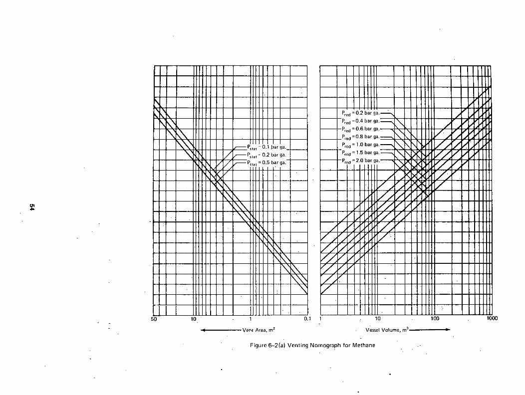
5 0 1 0 "
I I / ,
\x I \
~ P s t a t 0.1 .bar ga._
/ ~ Pstat = 0.2 bar ga.
Pstat = 0 . 5 b a r g a . - I I l I I ' I II I I
\
1
Vent Area, m 2
m
i
I I I I 1
I ~ \ 11 I ~ 1 1 1 ~
0.1 1 .: 10
Vessel Volume, m 3
100 1000
F igure 6 -2 (a ) Ven t i ng N o m o g r a p h f o r Me thane .-

( j n O l
5 0 I 0
q
I ' - 0 .1 I 10
Vent Area, m 2 : - Vessel Volume, m 3
Figure 6 -2 (b ) Vent ing Nomograph for Propane
1 0 0
Im -
1 0 0 0

01
50
\ \
\ \ X \,'R
\
ill1 Ill[Ill 1 1111 ~"--Pstat = 0"1 bar ga" 1111 ,/~Pstat=O'2barga', 1111 "//~Pstat=Ogbarga I I l l I I " I
111,1,'/. / IIII \ ,HI,I'" "" IIII \ X , I ~ ~ 1111 \ '~[11 III
Il l l ', x.,,, IIII II11 \~,k, IIII II11 ~ : X III t I111 ~,~111 I111 ~ 1 llll ~L~, II11 1]~" <~. 1111 1111"~,
III1 1111 tttl fill I111 II11 II11 1111 Illl
10 1
Vent Area, m 2
0.1
11111111 1111 1 I P;e;:6.~ ~'~';.-~ 1'11 11 "re~=O'"barga'--" \ I 1] 1 I. Pred =0"6barga'~-~ \ i ' ~ \ 1 11 J~1
P r e d = O ' a b a r g a ' ~ ~ "~ \ J II / " 1 , ~
Pred = 1.0 bar g a . ~ ~\ " J ,~\ \ ~ ~l I I ~ --Pred = 1.5 bar g a . ~ ~'\ \ \
~ - - P r e d =2.0 bar g a , ~ \ • \
1111 / >~ / , Ill[ / ' , / ~ , , ~ . ~ " / " I I
,kf fL/ / , ~ ~,'L,,t"II I I I
~ / / ~ / ' . , r ] l l I II I I ~ / . , / , / " II11 111. l / . , / I111 I I1 I / Illl II1 I
1111 111 I 1111 111 I l l l l I l l I
i " 10 100
Vessel Volume, m 3 •
1000
Figure 6-2(c) Venting Nomograph for Coke Gas

t.ln
• i
' 1 " , . - o . "
• , : . . _"
. . 5 q .10
1- ' l l l l i 1 ! I l l I 11111 Ill i !!! j]
____L~r~o:O'~roa'--~ 1 ~ P . e d = 0.6 bar ga. ". , "~ __~__Pred=0.8 barga. ~ \ \ > ~., I .~---J--Pred = 1.0 ba'r ga.--'-~" \ \
Pped = 1.5 bar ga . -~x \ - ' ~ \ ' ~ L . --Pred = 2.0 ' \'~,~ ~ '~
. \ \
• . ~ J "
f /
/
J , "~
ii ~. "/ • r j ]
i
' i
i •
!
i .
1 I
0.1 1. 10
Vessel Volume, m 3
Figure 6-2(d) Venting Nomograph for.Hydrogen
1 •
Vent Area, m 2
I I ] " /
i
',100"
. D
1000
o , Y~ - r "

6-3.2 Vessel Appurtenances. The presence of internal appurtenances within vented equipment can result in turbulence which may result in transit ion from deflagration to detonation. When the equipment contains internal appurtenances, an expert should be consulted to determine i f the potential exists for a detonation to occur. (See Reference 51 for further information.)
6-4 Use of the Nomographs with Hydrogen. The user is cautioned that hydrogen/air deflagrations can readily undergo transit ion to detonations. I t is therefore recommended that, before using the nomograph for hydrogen (Figure 6-2(d)), consideration should be given to the potential for a detonation to occur. This may require test work and consultation with an expert on the subject.
6-5 Effect of High Ignit ion Energy.
6-5.1 The amount and type of ignit ion energy can affect the effect ive flame speed and the venting. The' exact amount of ignit ion energy which may occur in vessels or equipment cannot normally be predicted. In many industrial cases, however, the ignit ion energy can be quite large.
6-5.2 A typical case is that of two vessels connected" by a pipe. Ignit ion in one vessel wi l l cause two effects in the second vessel. Pressure development in the f i r s t vessel wi l l force gas through the connecting plpe into the second vessel, resulting in an increase in both pressure and turbulence. The flame front wi l l also be forced through the pipe into the second vessel, where i t wi l l become a very large ignit ion source. The overall effect wi l l depend on the relat ive sizes of the vessels and the pipe, as well as on the length of the pipe. This has been investigated by Bartknecht, who found the effects can be quite signif icant (Reference 52). Pressures developed in the pipeline i t se l f can also be quite high, especially i f the deflagration changes to detonation. When such conditions prevail in equipment design, the reader should refer to Reference 52 or should consult a s p e c i a l i s t .
6-6 Extrapolation of Nomographs.
6-6.1 The lowest Pstat value on the homographs is 0.1 bar ga; the lowest Pred value is 0.2 bar ga. I t is sometimes desirable to vent equipment at lower pressures, with resulting lower maximum pressure developed during venting (Pred)- To determine the necessary vent area requires extrapolation of the homographs. A graphical approach is shown in Figure 6-6. Such a graph wi l l need to be constructed for each vessel size.
6-6.2 In Figure 6-6 the vent areas for a lO m 3 vessel were taken from the four gas nomographs at constant Pred, but for d i f ferent values of Pstat. Similar graphs can be constructed for various values of Pred. This graph allows interpolation and extrapolation, thus extending the u t i l i t y of the basic homographs.
6-6.3 Recently published papers have proposed calculation of vent areas for gases on the basis of. fundamental flame and gas flow properties and experimentally determined constants (References 22, 74, 75). These calculation procedures have not yet been fu l ly tested against the venting nomographs. The venting homographs are to be taken as the f inal authority within thei r applicable ranges of Pstat and Pred.
The user is cautioned not to extrapolate the homographs below 0.05 bar ga for Pstat nor below 0.1 bar ga for Pred. For values below these refer to Chapter 4. Pred should also not be extrapolated above 2.0 bar ga, the upper l im i t in the nomographs. Pstat can be extrapolated upward, but i t must always be less than Pred by at least 0.05 bar.
"E
8 >
1.0.
2.0' I
I
I Oo not
J extrapolate II below 0.05
bars gage
I O" I
J ,
V = 10 m 3 Fred = I bar
0 0.05 0.4
Psta'{" bar ga.
08
Figure 6-6 Extrapolation of Nomographs. (Reference 54)-
6-7 Effect of I n i t i a l Elevated Pressure.
6-7.1 The effect of i n i t i a l pressure must be correlated on the basis of absolute pressures. The data from Reference 55 serve as a basis for correlating pressures developed during venting as a function of the i n i t i a l absolute pressure of gases in the vessel and as a function of the absolute pressure at which the vent opens. I f the rat io of vent bursting pressure to i n i t i a l gas pressure is kept constant and i f vessel size and vent size are kept constant, the pressure developed during the ventlng'of propane combustion wi l l vary approximately as the 1.5 power of the i n i t i a l pressure. The power exponent for propane varies from about 1.2 for larger vent ratios (A/V2/3 = 0.3) to about 1.5 for smaller vent ratios (A/V z/3 = O.l). For hydrogen, the exponent ranges from ] . l to 1.2.
6-7.2 I t is .recommended that the 1.5 power be used in extrapolating from the nomograph for gases having K o values close to that of propane. For hydrogen~ the recommended exponent for increased i n i t i a l pressure is 1.2; for ethylene, 1.4. The l a t t e r value has not been validated by test. The correlation may apply to i n i t i a l pressures up to 4 atmospheres absolute, but this also.i~ untested.
6-7.3 Based on his extensive experimentation, Bartknecht (Reference 3) maintains: "The nomographs are based on an operating pressure of l bar (absolute), but they may be usedwithout correction for operating pressures up to 1.2 bar (absolute).. For higher operating pressures, suf f ic ient experience is not y e t available. For the time being i t should be assumed that when the operating pressure is raised above normal (atmospheric) pressu're, the reduced explosion pressure (Pred) wi l l show a proportional increase for a given constant re l i e f venting area."
6-8 Effect of I n i t i a l Temperature. The effect of i n i t i a l temperature is discussed in this Guide in Chapter 2. In most cases an increase in i n i t i a l temperature wi l l result in an increase in maximum rate of pressure rise and a decrease in the pressure generated by combustion in an unvented vessel. I t is therefore believed that no adjustment in the estimated pressure developed during venting needs to be made for an increase in i n i t i a l temperature (Reference 56). The same may be true for i n i t i a l temperatures below ambient.
58

6-9 Effects of Combinations of. Variables. There. are insuf f ic ient data to'determine precisely how combinations of variables may af fect the maximum- pressure developed duri.ng venting (Pred)- On'the basis of test work recently conducted (Reference 57), i t appears that ~the effects of i n i t i a l turbulence, ( i . e . , prior to ignit ion) may not be s.ignificant when the i n i t i a l pres'sure is above l.O bar ga. In such cases an allowance would only. be made for the i n i t i a l pressure above atmospheric, but not for turbulence.
6-I0 Deflagration ?f Mists of Combustible Liquids. Combustible mists wi l l bu'rn not only at. temperatures above the flashpoint temperature of the l iquid but also. at temperatures below-the flashpoint temperature (See References 58 through 61). In this sense, mists are similar to dispersed dusts, which may also be ignited at any i n i t i a l temperature. The design of explosion venting for many combustible mists can be based on the propane venting nomograph., For more detail 6n combustiblelmists see Chapter 2.
6- I I Deflagration of Foams of Combustible Liquids. _ Foams'of combustible li'quids ,can burn.' I f the foam is "'
produced by bubbling a i r through theliRuld', the bubbles wil l . contain a i r for burning. Combustion characteristics wi l l depend on a number of properties such as the specific l iquid, size of.'bubble, and . thickness of bubble filmL There is, however, a more hazardous case. I f a combustible ,liquid is' saturated with a i r under pressure and i f the l iquid phase is then released from pressure with the formation of a foam, the gas phase in the bubbles may be preferent ial ly enriched in oxygen. This-is because the so lub i l i ty of oxygen in combustible liquids is' higher than that of nitrogen. The increased oxygen concentration w i l l . result in intensified combustion. I t is therefore recommended that combustlble foams be carefully tested relati.~e to design for deflagration vent ing. .
6-12 Venting Deflagrations of Combustible Gases Evolved from Sol'ids. In certaln processes combustible gases may evolve' from solid materials., These ga~es may Form combustible mixtures with any oxidant present. ~I f ~he solid is i t se l f combustible, and is.dispersed in the gas/oxidant mixture, as'mlght be the case in a fluidized bed dryer, a "hybPid" mixture results. For hybrid mixtures use the-nomograph.that applies to the component that requires the larger vent area, which is usually the" gas. See also Section 7-8 for more detai l .
6-13 "Venting of Deflagrations in Conveylng and Venti lating Ducts. Most deflagrations.of combustible gas mixtures inside ducts occur aL i n i t i a l "internal pressures of.nearly.atmospheric.' The venting of .. deflagrations in. such ducts.is di:~cussed in. Chapter 8.
Chapter-7. Venting of Deflagrations of Dust Mixtures in High Strength Enclosures - .
7-I Introduction.
7-1.1 The most comprehenslve.design bases for venting of dust deflagration~.are contained in VDI Richtl inie 3673, published "in'Germany (Reference 62). This work is based on data obtained from an extensive test program involvin~ four dusts and'four vessel sizes: l , • lO, 30,' and "60 m~." The homographS; developed from the
. test data are reproduced here as Figur'es.7-1(a) through 7-1(f) . The nomogr~phs apply.to vessels of L/Dnot over 5.
7-1.1.1 As an alternative to Figures 7-1(a)', 7-1(b), and 7-1(c), the following equat~ol may be used to determine the necessary vent area. This equation was developed to reproduce the values "obtained From the homographs and is presented here as a convenience for the user of .this guide. (Reference 50) The equation is:
Av = (a) IV 2/3 ] [Kst] b [Pred] c
Where a , = 0.000571 (e) 2Psta1: b ' = ' 0 . 9 7 8 ( e ) - ° ' ~ ° ~ p s t a t c = - 0 . 6 8 7 " ( e ) ° ' 2 2 6 P s t a t
and A v = v e n t a r e a , m z V = enclosure volume, m 3 e = 2.718 (baseof natural.logarithm)
Pred reduced pressure, bar ga ." 59
Pstat = vent closure release pressure, bar ga Kst = deflagration index for dust,.'bar-m
sec
Since this equation is derived from the homographs, i t is no more-accurate than the nomographs themselves. The equation is subject to the same l imltat ions as the
.nomographs and, therefore,.should not be used for indiscriminate extrapolation; serious errors !n the value of Av wi l l occur i f this is done.
7- ' I . I .2 As an alternative to Figures 7-1(d), 7- l (e) , and 7-1(f) , the following equations may be used to determine the necessary vent areal Thes6 equations were developed to reproduce the values obtained from the homographs and are presented here as"a convenience for the user of this guide. (Reference 63) The equations are: . .
For Figure 7-1(di, (Pstat = O.l bar g a ) 0.96027
Log Av + C = 0.67005 (Log V) + (P/ed)O'21 '°
where Av : vent area, 'm 2 = V = enclosure volume, m 3
Pred = reduced pressure, bar ga C = 1.88854 for St-I dusts
= 1.69846 for. St-2 dusts , ' = Ii.50821 for St-3 dusts
For Figure 7-!(e).~ (Pstat = O.2'bar ga)" 1.03112 "
Log A~ + C = 0.67191 (Log V) + (Pred) 0"3
where Av = vent area, m 2 V = enclosure volume, m 3
Pred = reduced pressure, bar ga.' C = 1.93133 for St-1 dusts
= 1.71583 for .St-2 dusts = 1.50115 for St-3 dusts
For Figure 7-l i(f), ' .(Pstat = 0.5 bar ga) 1.20083
Log Av • C = 0.65925 (Log V) + (Pred) 0"3916
where Av = vent area, m 2 V = enclosure volume, m 3
- ' Pred = reduced pressure, bar ga C = 1.94357 for St~l dusts
= 1.69627 for St-2 dusts • = 1.50473 for St-3 dusts
Since these equations are derived from the ' nomographs, they are'no more accurate than the nomographs themselves. They are subject to the same l imitat ions'as the nomographs and, therefore, should not be used for indiscriminate extrapolation; serious errors in.the value.of A~'will occur i f this is done.
7LI.2 "Figures 7 - l (a i , (b)," and (c) are based on the Kst values "for the individual dusts, as determlned by test procedures described in Appendix A. Figures 7-1(d), (e), and ( f ) are based on the dust classes St- l , St-2, and St-3, respectively. These du'st classes represent a range of Kst values,Las shown i~ Table 7-I .
Table 7-I Hazard Classes of Dust Defl'agrations ~'2
Hazard K s t , 3 ' ' ": C l a s s b a r m / s e c ' _ _ ,
St-I ~ 200 St-2 201 - 300 St-3 > 300
IThe application of the nomographs is limited by an upper Kst value of 600.
ZSee Appendix D for examples of Kst values.
3Kse values were determined in approximately spherical calibrated test vessels of at least 20 l i t e r capacity.
7-I .3 Combustion v'enting characteristics of dusts of the same chemical composition vary with the physical properties such as size and shape of dust part ic le, moisture content, and others. See Subsection 2-2.1.2 and Appendix A for more information on this subject.

10 1 '
q Vent Area, m 2
100
Vessel Voiume, m 3
o .
o~ ~o
0.1 1 10 100
Figure 7-1 (a) Vent ing Nomograph for Dus ts - Pstat = 0.1 bar ga.
1000

O'J
l ~ IIII ~ P L
[ I b k \ " ]
'kPk \ ~ \ IIII' ,NJ',k\ \ ] \ ,, I I I I / , ] '~k'\\ \ " X I I I I . , . , ' k l l , ; ~ \ \ \ [ \ N i l I J/ / 3,4",k'~\\ \ \ \ N, ' f [ / " / " 1N,.'E,,J \ x" k \ i \ ' N J~KL,," / 11 'h', \ 'X k ~ ~ . ",,1"14d> ~" / • 111 " , " , , \ r ~ \ \ \ 134~"x" I I I ~,NN ~X\N[12%~:3 I I I \ ~ \ \ \ N Y I ~ " ~"~ I I I I \~ .~ \ " , ~ X %,
II I \\NJ3CJ2 ~ x I I I \ " ¢ k ~ k \ I I I . ' ~ " x I I I • ~ , \ I11 I l l , X \ II1 I I I I " II1 I I I I ~ III IIII ]]1 .[]]] ]]1 I l l l
111 I t l I/I I.l.I
-I]l I l l l
"' 'tl] ]11 -:1 I l l I l l l II1
" ' Ill 1II 1Q0 ~ 10 :
III1.11 I .I K St, bar.m/sec - - -
/ - - - - 5O / z ~ / / - ~ 75
., / ~ 100 / / , / / ~ 15o
• ~ 200 : / . / / F - - 250 / / . , / / / ~ 3 0 0 / / / - - 4uo / , / / - - 500" ~-/~ 600 : ' ;c / IIIII K , . ~ \,
X X " ~ \ l l I I I
\ ~ \ , \N.1"11..I
X X \ L I r'kl',
N x x " ~ t s X,
\ \ \ \ \ \ l l i \ , \ \ \
I 0.I
Vent Area, m 2
lO
. vessel Volume, m 3
F igure 7-1 (b) V e n t i n g N o m o g r a p h fo r Dusts - Pstat = 0.2 bar ga.
400 1000

I'kll Ir'k
H I N.Pk [IN." 1'14 I" N, Pk I&]'[" L'I~" IR~k"
II]~ II1 III I I I I I I I I I III III III III 111 III I I I I I I I11 III III
I l l l I I I I I I I I I I I I 1111 [111 [111 II I I I I I I III
[111 H[I
!o0
\ ,, \
, , \ k \
<
N \ I11
\ Iit' " k \ \ I /
~ , ' , , \ N 2 ~ ¢ x ~ \ \ \ l ~ l X e
\ \ \ N X I ~ x NNNX~,,
~ C
IIIBb ]111 '~ IIII IIII IIII IIII IIII
ti.t IIII
II 1111 IIII Illl IIII IIII
10
/ / , / / / r - - 200 •
/ / 250 I I / Z " / / / / , . 300 / / / / , 400
X / ~ ~ 5 o o / X - - 6 o o X k ~ , / v N ' \ ,, ,,.N-N \ i \ \ \ X
"~, XN \ \ \ "
\ \
\ \ , \ \
\ . " \ \ x \ \ \ \ , , ' \ \ \ \ \
\ ,
\ \ \ "1
1 . 0.1 1
Vent Area. m 2
10
Vessel Volume, m 3
100 1000
Figure 7-1 (c) Vent ing Nomograph for Dusts-Pstat = 0.5 bar ga.

O}
1 0 0 10 '
£ . , ,"
1 '
Ven t Area,. m r . . . . , .
0.1 1
"1.0 " - -
10 " : 100
Ves_sel Vo lume , m 3 . , . , . . . . ~lm
' F i g u r e 7 - 1 (d ) V e n t i n g N o m o g r a p h s f o r Classes o f Dus ts -Ps ta t = 0 .1 b a r ga.
,1000 • =

100 10 100
f / /
/ / / -= f ,,," f / / ~ x , ,
/ /
J~iJ I I I I . ,
Pred, bar ga,
0.8 ---, 0.8 " ~ 1.0 ~ 1.5 ~ ~ 2.0 - - - - , ~
i i I I |
i l
1 0.1 1 10
Vent Area, m 2 Vessel Volume, m 3
" i I
1 I
L |
I
Figure 7-1 (e) Venting Nomograph for Classes of Dusts-Pstat = 0.2 bar ga.
I I
I1 I1 II
II 11 , i
I I I I
II ! 1
I I
il | |
II | 1
I I
J !
1000

, ( , n . ° ,
°
?
1 0 0 10
4
1
Vent Area, m 2
• 0 . 1
• / / •
/ I . / /
; / / z "---~ 7 / i /
, z - ~ 7 ~ - r - " / i
L / "
I ,
. - i i 1
• ' I I I I - .
l I , . : : j • ]
I I | l l : I P I J
. 1 + 1 . . . .
' P red-- bar ga.,
. 0 . 6 _ _ . N ,
0 . 8 - ~ : -
N - 1 . 5 ~ ~ ~ \ \ L
: \
J
I
. ~ !
7 . j ~ , f
. / / / / . r A . ~ / :
f J I ' I
i
-I , i
• i 2. '
I l
I
! I
• ! ;
1 0 " ' 2 " " .
V e s s e l V o l u m e , m 3
Figure 7-1 (f) Venting Nomograph for Classesof Dusts- Ps,a~ = 0:5 bar ga.
i i
i i • .
m i
I '
k "
b, r , ~
f / ".]
p , . i ~ " ! I
: ! : i '
- r
: i . i
' I I - ' •
I 100
• . IL
..
. " , ,
° . ; .
,! I
! i
I : 1
. ! i I:
,4'
2
|
!
!
- i
I t
I "
I
I
: i
E I t
t :
1 0 0 0

7-2 Use of Dust Nomographs.
7-2.1 The necessary vent area for a dust can be .. determined from the.homographs as a function of the Kst value or the dust hazard class, the vessel volume . . . . . and strength, and the relieving pressure of the vent closure.
7-2.2 The vent areas predicted by the two sets of~ homographs described in Subsection 7-1.2 may not completely agree. The agreement is, however, suf f ic ient ly close for practical applications. When experimental~values of Kst are a~ailable,Figures 7-1(a) through 7-1(c) should preferably be used to establish the minimum vent.area required. The - homographs themselves are not exact and the' determination of Kst:can introduce additional errors. However, the homographs have been shown to predict the required vent area with suff ic ient accuracy. for dependable use in industry. . .
7-2.3 Dusts of the same hazard class which have maximum deflagration pressures not greater than 9 bar ga require less vent area than those which have a maximum deflagration pressure greater than 9 bar ga. The nomographs in Figures 7-2(a) and 7~2(b), based on test work reported in Reference 84, are limited to dusts whose maximum•deflagration pressure in closed vessel tests (see Appendix A) are not greater than 9 bar ga and only for vent Opening pressures not exceeding O.l bar ga. The l imitat ions stated in Subsection 7-2.2 apply to these homographs as well~ Also, none of the equations in Subsections 7 - I .1 . I or 7 - I . I . 2 are applicable to these two homographs.
7-3 Extrapolation and Interpqlation of Nomographs.
7-3.1 The dust homographs can be extrapolated and interpolated using the graphical techniques described in Section 6-6.
7-3.2 The user is cautioned not to extrapolate the nomographs below 0.05 bar ga for Pstat nor below 0.1 bar ga for Pred. For values below these, use the calculation procedure in Chapter 4. Furthermore, Pred should not be extrapolated above 2.0 bar ga, the upper l imi t in the nomographs. Although'Pstat may be extrapolated upward, i t must always.be less than Pr&d by at least 0.05 bar. The venting homographs are to be taken as the final authori ty.within their applicable ranges of Pstat and Pred.
7-3.3 The dust homographs were developed for essentially atmospheric i n i t i a l pressure, before ignit ion, and they apply to i n i t i a l pressures up to 0.2 bar ga. No guidance is .available at Rresent for systems operating at higher i n i t i a l pressures.
7-4 Bins, Hoppers and Silos. " ..
7-4.1 Deflagration venting for bins, hoppers, and silos must be from the top or the upper side, above the maximum level of the material-contained and must be directed to a safe outside location (see Sections 5-5 and 7-7). In som~ instances the required vent area may be as large as the vessel cross section. In these cases the entire vessel -top can be made to vent. Space must be available above the top to allow i t to open suf f ic ient ly . The'top should be as'lightweight as possible. (See Subsection 3-4.3 for effects of. vent- mass.) Large diameter tops of this type cannot be'made self-supporting and wi l l require internal supports. Panels which make up the top mustnot be welded or otherwise attached to the internal roof supports. As an alternative, individual vent closures may be located on the top or the side (above the maximum level of solids). When vent closures are located on the side and top of the vessel, the maximum useful area for venting wi l l correspond to the cross-sectional area of the vessel. The reader is cautioned that deflagration venting of these vessels can result in higher pressures than expected from the venting nomographs. (Reference 85)
7-4.2 The vent area required is determined by the strength of the vessel. I f this vent area is larger
• than t6e vessel cross section, the vessel needs to be strengthened to contain a pressure consistent'with the available vent area. In al l cases the total volume of the vessel should.be assumed to contain a suspension of the combustible dust in question. That is, no credit should be taken for the vessel being part ly fu l l of sett ledmateria1.
7c4.3. Deflagration venting is sometimes accomplished by means of ventpanels distributed around the wall of the vessel just beneath the top._ In such cases care must be taken not to f i l l the vessel above the bottoms
, 'of. the vent panels. Otherwise, large amounts of dust may be blown out into the atmosphere, be ignited, and form a large f i reba l l . Furthermore; dust piled above the bottoms of vent panels can hinder vent panel
opening and can also result "in Pstat values which are higher than design.
7~5 Effects of Vent Ducts. The e'ffects of. vent ducts are discussed in Section 5-4.
7~6 Venting of Enclosed Bag Dust Collectors. I t is desirable to design bag f i l t e r vent panels in such a way as to minimize the potential for bags and cages to interfere with the venting process." The f i l t e r medium may not adequately segregate the clean and d i r ty sections of the collector during the deflagration. Therefore, the entire volume of each section should be used when calculating the vent area for that section. I f the volume of the clean section above the tube sheet is re lat ive ly small, the vent area required may be achieved by placing the vents on the dir ty-sect lon.
7-7 Flame Clouds from Dust Deflagrations. Normally when Oust deflagratlons occur, there is far more dust present than there is oxidant to burn i t completely. When venting takes place, large amounts of unburned dust are vented from the vessel. Burning continues as the dust mixes with additional a i r from the surrounding atmosphere. Hence a very large and long f i rebal l of burning dust develops, whichcan extend downward as well as upward. The size of the f i rebal l depends on
' many factors. In one deflagcation venting test a dust f i rebal l extended at least 4 m below the level of the vent and about 15 m horizontally. Personnel enveloped by such a f i rebal l would l ike ly not survive. The potentiall.y large size of the f i rebal l extending from the dust deflagratlon vent should be considered when locating vents.and vent ducts so as to. avoid hazards to adjacent equipment and personnel.
7-8 Hybrid Mixtures.
7-8..1 A mixture of a combustible gas and a combustible dust constitutes a hybrid mixture. Such a mixture may be ign i t ib le even i f both constituents are below thei r respective lower flammable l imi ts . The properties of hybrid mixtures are extensively discussed by Bartknecht (Reference 3). ' Certain dusts which do not form combustible mixtures by themselves, may do so i f a combustible gas is added, even i f the l a t t e r is at a concentration below i ts lower flammable l im i t . The lower.flammable l imi t concentrations of most combustible dusts are decreased by addition of combdstible gases, eyed when the concentrations of the l a t t e r a~e below'~heir lower flammable l imi ts . The minimum ignit lon energy is also reduced below that for the dust alone.
For additional information see Subsection 2-2.2.1.
7-8.2 The effect ive Kst value of most combustible dusts is raised by the admixture of a combustible gas, even i f the gas concentration is below the lower flammable l im i t . This in turn leads to an increase in the required vent area. For hybrid mixtures, use the nomograph for the component that requires the greater vent area. This is usually the gas.
BB

10 1
bar ga. r°~, . ' - - - - q ~ q
o:+o-~ -I 1 O0
2 . 0 0 ~ 1 ~ " i , j
. #
, / / t / -.1 - - - ~ 7 -
/ / . , ~ . . . .
f L ~ ' , . " ;
+ j - ~ j • , ++
I 0.1 . 0.01 1 10
q Ven t Area, m = Vessel ~ /o lume, m 3
Figure 7-2(a) A l te rna te Ven t ing Nomogrbph fo r Dusts of Class St -1 whose M a x i m u m Def lagrat ion Pressure Does Not Exceed 9 bar ga.
I] II
J
f J / : t ! ! ! ! ! I I l l l l
t t t t t t £
: ; : : : : :
: i L I I L I - + + +++++
:++++++ " " : ! ' ! E ! ! !
1 I I I I I 1
1 I I I I I I •
. . . . . lObO 100 '
i_

q Vent Area, m 2
10
- - =
1 0.1 0.01 10 100 1000
Vessel Volume, m~ •
¢10
Figure 7-2(b) Alternate Venting Nomograph for Dusts'of Class St-2 whose Maximum Deflagratiqn Pressure Does Not Exceed 9 bar ga.

Chapter 8 Venting of Deflagrations from Pipes, Ducts, and Elongated Vessels Operating
At or Near Atmdspheric Pressure
8-I Scope. This chapter applies to systems operating at pressures up to 1.2 bar absolute.
8-2 General. • -'
8-2.1 Several factors make the design of deflagration vents for pipes, ducts, and elongated'vessels (length to diameter ratios of 5 or greater) a di f ferent problem than the design of deflagration vents for ordinary vessels and enclosures. These include:
(a) The geometry of large L/D ratios promotes rapid acceleration of flames. Acceleration to very high flame speeds, or even detonations, can occur.
(b) For an individual vent, any. vent area exceeding the cross-sectional area of the pipe, duct, or vessel wi l l not be effect ive in further reducing the deflagration pressure. The cross-sectional area is the maximum effect ive vent area obtainable.
(c) Turbulence-producing appurtenances such as valves, elbows, and other f i t t i ngs are frequently present. The turbulence produced can generate sudden flame acceleration and a Consequent rapid increase in pressure.
(d) Ignit ion of a combustible mixture in a vessel to which a pipe or duct is attached results in a flame front that generates considerable turbulence ahead of i tsel f 'and precompresses the ga's in' the pipe or duct. When the flame front reaches the entrance to the pipe or duct, i t is fu l l y developed and turbulent. The result is a flame .front that propagates into the pipe or duct with much greater i n i t i a l violence than that which wouldresult from spark ignit ion in the pipe or duct i t s e l f .
(e) Conversely, when a flame front propagates through an inadequately vented pipe or duct and then enters an enclosure or vessel containing a mixture in the flammable range, the resulting j e t of flame is such a massive ignit ion source that any deflagration venting in the vessel may be rendered inadequate.
8-2.2 The design of adequate deflagration venting for pipes, ducts, and elongated vessels is further complicated by the fact that there has been relat ively l i t t l e systematic test work published on this subject . . The guidelines in this chapter are based on information contained in References 3 and 64 through 71 and are thought to provide reasonable protection, but their use should be tempered by sound engineering judgement for specific applications. Any deviation from these guidelines should be in the direction of more, rather than less, vent area.
8-3 Design Guidelines.
8-3.1 For pipes, ducts, or elongated vessels having cross sections other than circular, the hydraulic diameter should be used in the correlations that fol low." The hydraulic diameter is equal "t~ 4A/p, where A is the area of the cross section and p is the perimeter, of the cross section.
8-3.2 The total vent area at each vent location should be at least equal to the cross-sectional area of the duct or pipe. The required vent area can be accomplished by using either one 'or more than one vent at each location.
8-3.3 Any pipes or ducts connected to a vessel in which a deflagration can occur may also require deflagration venting. For gases and Class St-3 dusts, a deflagration vent whose area is equal to the cross-sectional area of the pipe or duct should be provided at a location on the pipe or duct that is no
more than two diameters distant from the point of connection to the vessel. For Class St-2 and St -1 dusts, evaluations should be made to 'detemine' the ' need for any addit ional yenting on a case by cash basis.
8-3.4 Deflagration vents'shoul~ be qocate'd .close'tO possible ign i t ion sources, when the'se source~"can be identifie~. • " : .......
8-3.5 For systems handllng gases, unless appropriate tests indicate otherwise, pip@s and ducts conlaining obstacles should be prdvided with dbflagration ~ents on each side of the obstacle. When designing for a Pred of 0.2 bar or less~ two'vents., each ~f which has an area equal to the cross-sectional area~of th~ duct'~or pipe, should be placed on each side of the obstacle at distances from the obstacle of 3 diameters and 6 diameters, respectively. When~de~igning for a Pred of greater than 0.2 bar, one vent'on each'side ofthe obstacle at'distances of 3 diameters shoOld~bb ~ suf f ic ient . At the present time~ the're'is not suf f ic ient information available for venting'o.f dusts. An obstacle is defined here as an'e~bow, tee, flow sp l i t t e r , o r i f i ce , valve, or any appurtenance that blocks'more than 5 percent of the cross~sectional area of the pipe or duct.
8-3.6 The weight of deflagration vent'clpsures should not exceed 2.5 Ib/sq f t for each ~quare foot of f~ee vent area.
8-3.7' The release pressure of vents ~bould be" as much below the design value of Pred'as possible, ' consistent with operating conditions, but should not exceed one half of the design value for Pred- 'Covers may be held by magnets or springs.
8-3.8 Deflagration vents must discharge to a location that wi l l notendanger personnel.
8-3.9 Consideration should be given to reaction forces that develop during venting. See Subsection 5-2.9.
8-4 Determination of Pred for Pipes, Ducts, or Elongated Vessels that are Vented at One End Only.
8-4.1 The curves in Figure 8-4(a) should be used to determine the maximum allowable length of a smooth, straight pipe, duct, or vessel that is closed on one end and vented on the other when no additional deflagration vents are provided. I f L/D ratios greater than those shown in the figure are present, there is a risk that detonation may occur. In these cases, the container should be designed to resist detonation pressures, provided with additional vents,, or provided with explosion prevention measures such as those described in NFPA 69,.Standard on Explosion Prevention Systems. Class St-l.dusts are an exception in that there is no evidence that large L/D'ratios can lead to a detonation of these dusts.
8-4.2 I n i t i a l Velocity 2 m/sec or Less--Gases. The curves in Figure 8-4(b) should be used to estimate the pressure developed in a pipe, duct, or vessel that is vented at one end only when the pressure results from deflagration of a gas/air mixture i n i t i a l l y flowing at a velocity of 2 m/sec or less. This'applies to gas mixtures having properties similar to those of propane. For diameters other than those shown, the curves should be interpolated. I f the p~essure developed may exceed the strength of the container, additional vents should be provided as outlined in Section 8-5.
824.3 I n i t i a l Velocity 2 m/see or Less--Dusts. The curves in Figure 8-4(c) should be used to estimate the deflagration pressure developed in a pipe, duct, or elongated vessel that is closed on one end and vented on the other, with no additional vents, when dust/air mixtures i n i t i a l l y flowing at 2 m/sec or less are ignited. I f the pressure developed exceeds the burst strength of the container, then additional vents should be provided as outlined in Section 8-5.
69
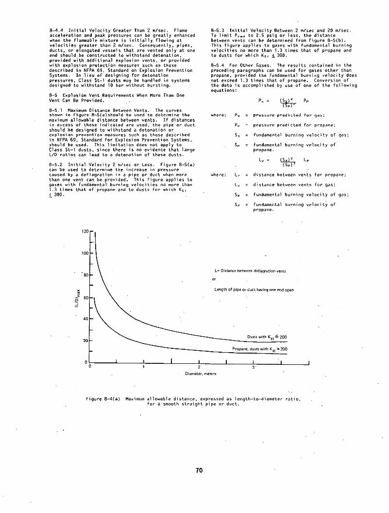
8-4.4 I n i t i a l Velocity Greater Than 2 m/sec. Flame acceleration and peak pressures can be greatly enhanced when the flammable mixture is i n i t i a l l y , flowing at velocit ies greater than 2 m/sec. Consequently, pipes, ducts, or elongated vessels that are vented only at one end shouldbe constructed to withstand detonation, provided with additional explosion vents, or provided with explosion protection measures such as those described in NFPA 69, Standard on Explosion Prevention Systems. In l ieu of designing for detonation pressures, Class St-l dusts may be handled in systems designed to withstand 10 bar without bursting.
8-5 Explosion Vent Requirements When More Than One Vent Can Be Provided.
8-5.] Maximum Distance Between Vents. The curves shown in Figure 8~5(a)should be used to determine the maximum allowable distance between vents. I f distances in excess of those indicated are used,'the pipe or duct should be designed to withstand a detonation or explosion prevention measures such as those described in NFPA 69, Standard for Explosion Prevention Systems, should be used. This l imi tat ion does not apply to Class St-l dusts, since there is no evidence that large L/D ratios can lead to a detonation of these dusts.
8-5.2 I n i t i a l Velocity 2 m/sec or Less. Figure 8-5(a) can be used to determine the increase in pressure caused by a deflagration in a pipe or duct when more than one vent can be provided. This figure applies to gases with fundamental burning velocit ies no more than 1.3 times that of propane and to dusts for which Kst < 300.
8-5.3 I n i t i a l Velocity Between 2 m/sec and 20 m/sec. To l imi t Pred to 2.5 psig or less, the distance between vents can be determined from Figure 8-5(b). This figure applies to gases with fundamental burning velocit ies no more than 1.3 times that of propane and to dusts for which Kst ~ 300.
8-5.4 For Other Gases. The results contained in the preceding paragraphs can be used for gases other than propane, provided the fundamental burning velocity does not exceed 1.3 times that of propane. Conversion of the data is accomplished by use of one of the following equations:
Px = L ~ P.
where: Px = pressure predicted For gas;
Pp = pressure predicted for propane;
Sx = fundamental burning velocity of gas;
Sp = fundamental burning velocity of propane.
S 2 Lx = ~ Lp
where: Lp = distance between vents for propane;
Lx = distance between vents for gas;
Sx = fundamental burning velocity of gas;
Sp = fundamental burning ~elocity of propane.
2°F~ o L ' i
0
L= Distance between deflagration vents
or
Length of pipe or duct having one end open
Dusts with Kst ~ 200
Propane, dusts with Kst :~ 200
I I I 1 2 3"
Diameter, meters
F i g u r e 8 - 4 ( a ) Maximum allowable distance, expressed as length-to-diameter rat io, for a smooth straight pipe or duct.
70

J
lo m
5 m
L
m
0 0
10 , - -
n
w
m
6 m
B
i
m
0 -'I .... I ,..I I I I I I • ; ' " 20 :. 40 - . , . 60 80
Length - to - diameter ra t io
F i g u r e 8 - 4 ( b ) Haxir, tum p r e s s u r e deve loped d u r i n g d e f l a g r a t i o n o f p r o p a n e - a i r m i x t u r e s f ] o w i n g a t ;-~ m/s o r l e s s in a smooth, s t r a i g h t p ipe c losed a t one end.
~ , . " : • ] t ~300 " r " " :
Kst = 200 "'
I I i ..... I I I 1 I I I 20 40 . 60 80
Length - to - diameter ratio
• F i g u r e 8 - 4 ( c ) .Maximum p ressu re .d .eve loped d u r i n g d e f l a g r a t i o n o f d u s t - a i r m i x t u r e s f l o w i n g a t ~ m/s o r l e s s ~n a smooth, s t r a i g h t p ipe c losed a t ' o n e end.
• •
71

0.3 D
0.2
Jo
i 0.1 c
0
j Kst,3oo • / ~ ! s t a n c e between vents
I 20 40 60 80
Length-to-diameterratio
F igu re 8 - 5 ( a ) Haximum p ressu re deve loped du r i ng d e f l a g r a t i o n o f dus ts in a p ipe o r duct when more than one ven t i s p rov ided .
15
F igu re 8 - 5 ( b )
PrOpane and dusts with KSl ~" 300 2 m/s and 20 m/s
I I - . I I l 2
Oiameler, meters
Vent spac ing r e q u i r e d to keep Preo from exceed ing 0 .2 bar ga.
72

8-5.5 I n i t i a l Velocity Greater Than 20 m/sec, or Gases Having Burning Velocities'More Than 1.3 Times That of Propane, gJ~ Dusts With Kst > 300. For these situations, vents should be placed no more than I to 2 m apart, or the pipe or duct should have a.design pressure capable of withstanding a detonation or explosion protection measures, such as those described in NFPA 69, Standard on Explosion'PrevebEio'n Systems, should be employed. : , .
8-5.6 Obstacles. For ducts or pipes containing obstacles as previously described, vents should be placed as specified in Subsection 8-3.5. Additional vents, as specified elsewhere in Section 8-5, may also be required.
8-6 Examples. . .
8-6.1 A dryer handling a dust whose Kst is 190 is 2 m in diameter and 20"m long and is.designed so that one end functions as an explosion vent. What pressure wi l l be developed during a vented-explosion?
(a) Check maximum allowable "length: According to Figure 8-4(a), an L/D of about 25 is allowable. The dryer has an L/D of I0, so this is acceptable.
(b) Maximum Pressure: According to Figure 8-4(c), a pressure of about l.O bar ga wi l l be developed in this equipment by the deflagration of this dust. Hence, the equipment must have a design pressure of at least this value..
8-6.2 A f lare stack is 0.4 m in diameter by 40 m ta l l and is equipped with a water seal at i t s base. What must i ts design pressure be in order to protect i t from the pressure developed by ignit ion of a fue l -a i r mixture having properties similar to those of propane?
(a) Check maximum allowable length: From'Figure 8-4(a), a maximum L/D of 28 is allowed. This stack has an L/D equal to I00. Therefore, i t must be designed to withstand a detonation ormust be protected by some other means.
8-6.3 A straight duct l m in diameter and I00 m long is to be protected by explosion vents. I t contains a hydrocarbon/air mixture having properties s imi lar ' to those of propane. What vent spa:cing is required to l imi t the deflagration pressure to 2;5 psig (0.17 bar) i f (a).the yelocity is less than 2 m/sec,.or (b) the velocity is less .than 20 m/see? In both cases, the vents are designed t ° open at 0.05 bar ga.
(a) From Figure 8-5(a), the spacing must be about 45 diameters (45 m) in order to l im i t the increase to 0.12 bar above Pstat. However, t~is v~olates the maximum allowable spaclng'of about 19 diameters: as indicated in Figure 8-4(a)'." Hence, the vent spacing should not exceed 19 m for this case. I t "is recommended that seven vents be provided, including one at each end.
(b) Fro~ Figure. 8-5(b), the vents should be placed no more-than 7.6 m apart. In order to'meet this requirement, i t is recommended that a vent be placed at each end and that 13 additional vents be evenly spaced along the duct.
8-6.4 Provide deflagration vents for the ducts in the system shown in Figure 8-6.4. Assume al l ducts are 0.6 m in diameter and that the dust col lector, dryer, and al l ducts have a maximum allowable working pressure of 0.2 bar ga and that the'maximum operating pressure anywhere in the system is limited to 0.05 bar ga. The system handles a class St-3 dust. I t is further assumed that the dryer and dust collector are equipped with adequate deflagration vents. Since the system handles an St-3 dust, i t is recommended that the provisions of Subsections 8-2.3 and 8-2.5 be followed. Therefore, the following vents are required:
- A and B, located two and f ive diameters distance, respect!vely, from the dryer outlet.
- C and D, located three and six diameters distance, respectively, from the f i r s t elbow.
73
- G, located two diameters upstream of the dust col lector in let .
• " ' " : , " t ;
- H, I , add J, located at the midpoints, respectively, of the three 1.5 m sections. Since these sections are less than three diameters in length, the second vents specified.in Subsection 8-2.5 ( i . e . , the vents to be located six diameters upstream and downstream of an obstruction) are not requi.red. ;
- K and L, located three and si.x diameters, distance, respectively, af ter the last~elbow. .
Additional venting is requi.red..for the 20 m s e c t i o n . At tO0 m3/min, the velocity in the lines is. 6 m/sec. Hence, Figure 8-4(b) should be used. Accord.ing to this curve, vents should be placed at intervals of 6 I /2 m or less. The distance between vents D and G is 15.2 m. Therefore, two additional vents (E. and F), located I/3 and 2/3, respectivel.y, of-the distance between O and G are required.
The total vent area at each vent location should be at least equal to the cross-sectional area o{ .the duct. This wi l l result inca value of O.2. bar ga. for Pred. According to. Subsection 8-2.7, the vent release pressure should be no higher than O.l bar ga.
Ouct Lengths
Dryer Outlet to first elbow Firl t elbow to dust collector Dust collector to second elbow Second elbow to fan inlet Fan outlet to third elbow Third elbow to end of duct
~ - .
El"
• T
5 m 20 m
1.5 m 1.5 rn 1.5 rn' 5 m
( ~ = Vent locations
D u s t '
Figure 8-6.4 Diagram For example in Subsection 8-6.4.
Chapter 9 Oescription of Deflagration Vents and Vent Closures- ".
"9-i General.
9-I.1 The deflagration vents and vent closures described in this Chapter have been designed to relieve the overpressure that results from a deflagration within an enclosure. ,-
9-1.2 Some types of vent and closure assemblies are commercially available and may be purchased ready-to- instal l . Others must be custom-fabricated on si te by the user. The following descriptions maybe used as a basis for the selection or design of suitable vent and closure assemblies.
9-2 Normally Open Vents. " '" "
9-2.1 The most effect ive deflagration vent is an unobstructed opening that has no c losure . Open vents are an option wherever equipment or rooms do not need to be to ta l l y closed. However, there are comparatively few situations where operations with an inherent• deflagration hazard can be conducted in open equipment.
9-2.2 Louvered Openlngs. Openings fitted :with fixed louvers may be considered as open vents. However,.the construction of the louvers par t ia l l y obstructs the opening, thus reducing the net free vent.area. The obstruction presented by the louvers decreases the flow rate of gases passing through the vent and increases the pressure drop across the vent. These factors must be considered when choosing louvered vents.
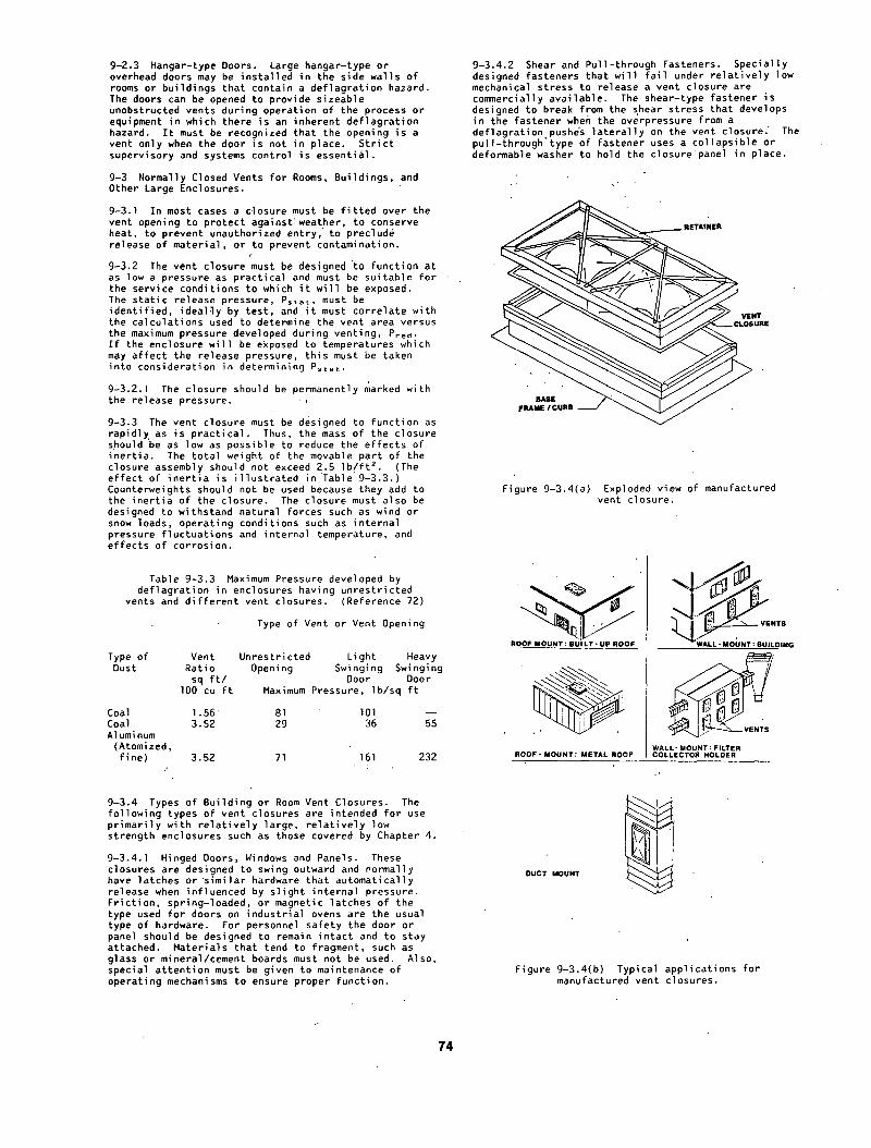
9-2.3 Hangar-type Doors. Large hangar-type or overhead doors may be installed in the side walls of rooms or buildings that contain a deflagration hazard. The doors can be opened to provide sizeable unobstructed vents during operation of the process or equipment in which there is an inherent deflagration hazard. I t must be recognized that the opening is a vent only when the door is not in place. St r ic t supervisory and systems control is essential.
9-3 Normally Closed Vents for Rooms, Buildings, and Other Large Enclosures.
9-3.1 In most cases a closure must be f i t t ed over the vent opening to protect against weather, to conserve heat, to prevent unauthorized entry, to preclude release of material, or to prevent contamination.
9-3.2 The vent closure must be designed to function at as low a pressure as practical and must be suitable for the service conditions to which i t wi l l be exposed. The stat ic release pressure, Pstat, must be identi f ied, idealqy by test, and i t must correlate with the-calculations used to determine the vent area versus the maximum pressure developed during venting, Pred. I f the enclosure wi l l be exposed to temperatures which may affect the release pressure, this must be taken into consideration in determining Pstat.
9-3.2.1 The closure should be permanently marked with the release pressure.
9-3.3 The vent closure must be designed to function as rapidl~ as is pract ical . Thus, the mass of the closure should be as low as possible to reduce the effects of inert ia. The total weight of the movable part of the closure assembly should not exceed 2.5 I b / f t 2. (The effect of i ne r t i a is i l lustrated in Table 9-3.3.) Counterweights should not be used because they add to the inert ia of the closure. The closure must also be designed to withstand natural forces such as wind or snow loads, operating conditions such as internal pressure fluctuations and internal temperature, and effects of corrosion.
Table 9-3.3 Maximum Pressure developed by deflagration in enclosures having unrestricted
vents and di f ferent vent closures. (Reference 72)
Type of Vent or Vent Opening
Type of Vent Unrestricted Light Heavy Dust Ratio O p e n i n g Sw ing ing Swinging
sq f t / Door Door lO0 c u f t Maximum Pressure, Ib/sq f t
Coal 1.56' 81 101 - - Coal 3.52 29 36 55 Aluminum
(Atomized, fine) 3.52 71 161 232
9-3.4 Types of Building or Room Vent Closures. The following types of vent closures are intended for use primarily with re la t ive ly large, re lat ive ly low strength enclosures such as those covered by Chapter 4.
9-3.4.1 Hinged Doors, Windows and Panels. These closures are designed to swing outward and normally have latches or similar hardware that automatically release when influenced by sl ight internal pressure. Frict ion, sprlng-loaded, or magnetic latches of the type used for doors on industrial ovens are the usual type of hardware. For personnel safety the door or panel should be designed to remain intact and to stay attached. Materials that tend to fragment, such as glass or mineral/cement boards must not be used. Also, special attention must be given to maintenance of operating mechanisms to ensure proper function.
9-3.4.2 Shear and Pull-through Fasteners. Specially designed fasteners that wi l l f a i l under re lat ively low mechanical stress to release a vent Closure are commercially available. The shear-type fastener is designed to break from the shear stress that develops in the fastener when the overpressure from a deflagrati'on pushe's la tera l ly on the vent closure." The pull-through'type of fastener uses a collapsible or deformable washer to hold the closurepanel in place.
URE
FRAME / CURB + - - / ~ ~ l J J
Figure 9-3.4(a) Exploded view of manufactured vent closure.
ROOF MOUNT: B U I L T - U P ROOF
R O O F - M O U N T : METAL ROOF WALL- MOUNT : FILTER COLLECTOR HOLDER
DUCT MOUNT
Figure 9-3.4(b) Typical applications for manufactured vent closures.
74

-The force of the deflagration on the.panel causes'the washer to be'pull'ed through • the mounting boleand'the panel can then ~e pushed away from the vent opening. Since these fasteners can be~"applied to a var!ety of "types and configurations of vent and ~losure assemblies, the 'resRonse of a given fastener to ~
'pressure di f ferent ia l cannot be predicted for anygiven application based'on' fastener test' data alone. Dynamic testing should be carried out to establish the Pstat for any given "fastener/venticlosure combination.
Shear and "pul]'-through fasteners are sui'table' for applica'tions where thevent design call's fo'r very large vent areas, such as the entire side wall of a ro~m..
. . !
9-3.4.'3 Friction-held Closures.. 'Some commercially availabl'e vent' and'closure'assenlblies use a fle~'ible" diaphrag~n he]d around i ts edges in a' restraining frame.' When a deflagration occurS, the pressure ' deforms the diaphragm, "pushing i t from i ts frame. (See Figures 9-3.4(a) and (b).) This type of vent and closure assembly is well suited for large stru'ctu~e~ such as rooms, buildings conveyor enclosures, si los, 'dust collectors and baghouses•~ and other large enclosures. It' is "also particularly' sui'ted to ductwork 'operating at dr' c~ose to atmosp.heric~.~Fessure.
In locations where personnel ~r equipment might be 'damaged by f ly ing ~phragms ~ethering' of the diaph'ragm to ' i t~ frame or other sa?ety measures may be necessary;
The material used fo;r the diaphragm sh~ul'd be durable, nonshattering, and should"n'ot exceed 2.5 I b / f t z. The diaphragm should be appropriately 'dimensioned and attached; - ' '
-"These veSt'and closure assemblie~ are capable of being tested by static:methods and by:simulated
. deflagrations corresponding.to the intended application. I t is~recommended that both stat ic and dynamic tests be conducted. .
9-3.4.4 '!Weak'" Roof or Wall Construction. A portion of a roof~or wall may bedel iberate ly designed to fa i l under s l ight overpressure. In thisitype of venting, suitable lightweight panels may be located between strong par t i t ion walls. In some cases the entire roof area is constructed as a blowout panel. In al l cases the weak wall or roof must be adequately anchored to prevent wind ] i~ t . ' '
9-4 Restraints fop Large Area Paneis. ,"
9-4.1 When large, lightweight'panels are used as vent closures (usually o~er entire wall areas), i t l i s usually necessary to tether the panels so they do not become missile hazards. The restraining method shown in Figure 9-4.1 i l lustra£es o~e method that is part icular ly suited for conventional single wall metal panels. The'key features of the system iHclude a permanent anchor between the panel and the building structural frame using a 2 in. w~de, 10 gage bar washer~ The length of the b~r' is equal to'the panel' width, less 2 i'n. and-less any overlap between'panel's. The bar washer/Vent panel assembly ~s secured'to the' building structural frame using at least three 3/8 in. diameter throOgh-bolts. "Shear fasteners or.col lapslble washers are used at the opposite end of the panel.
9-4.1.1 "Pop" rivets'~ave been used sd~cessfuily as the fai lure fastener. During deflagration tests using . th is 'design the pop'rivets fai led withi'n acceptable~ design l imits to all'ow rotation of the panel 'about the plastic"hinge formed by the attac'hment 9flthe panel to the building structural frame. ! ' , i
9-4.].2 Precautionary Measures for Aluminum Vent Panels. In tests of 21 gage corrugated aluminum panels, a tendency for the panels to tear out in the v i c in i t y of the through-bolts (see Figure 9-4.1) has been observed'. This ma~ be controlled by maintaining
at least"3 in.'.distance" between the "edge of thep.anel and the bar washer and by Hinging the panels to the Towest building structural member. This li.mits the amount of rotation l;hat can occur, thus'reducing the chance of tear-out.
, t .
' ''" au,ld,ng girt "' .. . ..
3/8 in. dia.. " , o~
" I ° ' " Bar washer" " "
• ( 1 0 g a . I ~ __ ( , Girt
- ~ Lap
' I I " - - - I I I . I ' ; • I I I I . M I I I " I I I I Vent panel . I
'I V , T. I.~_ l'Ear washer I
r~--~-~ I ~ - -
. E l e v a t i o n showing vent panels and bar washer assemblies
.; • , •
' Figure 9-4.1' Panel restraintsystem for single wall metal vent panels. ' ;
9-4.2 When th e vent closure panel is a double-wall type (such as insulated sandwich panels) the restraint sys'tem•describ'ed in Subsection 9-4.1 is not. recommen.ded. "The stiffness of the double-wall panel is muck great'er than that of' a singl e wall panel ~. The fo'rmation of t'he plast ic hinge.will o'ccur more'slowly and' rot'at'.io'h'of the.panel' may be'inc~)mplete. Both factors' wi l l tend to delay, or impede venting during a , ,. • • deflagration.
'The' r'es'trai6t~system shown in' Figure 9-4.2 i s ' ' recommended f'or'double-wall panels. For successful functioning, the panel area'is l imited to 33 f t 2 and i ts mass "to 2.5 Ib/fE z.
Vent panel'~l~" I • " ~ J I Sheetmetal subgirt I
I I / (10 GA') ~ , ~ Roof girder
1/4 in 'd ia '~ I V 9 lind rivet ~ l e ' / / Girt t thru-bolt ~ ~L |
' ' .I I for~deyebol t ICshockabsorber_ f reedomto /~ | (3/16 in. Thk.) move through
' ./11 X, II. " " Bar washer I I rope clips
I I \'fai,-safe ? I I \ ~%tth-elrng~l{4'in' dia.,4 ft. long galv. II , ~ 1 7 . wlrer°pe te ther
I.L. ff .=, . - .0 , . . 0o,=
'"2°I f n Close-up of shock absorber
, =
Figure 9-4.2 Panel res t ra in t system for double-wall insulated metal vent panel•
75

9-4.2.1 Tests employing fewer than three rope clips have in some instances resulted in slippage of . the tether through the rope cl ips, thus permitting the vent panel to become a free pro jec t i le .
9-4.2.2 Forged eyebolts are necessary. Al ternat ively, a 0.5 in. "U" bolt may be substituted for the forged eyebolt.
9-4.2.3 A "shock absorber" device with a f a i l - sa fe tether is provided. The shock absorber is a 4 in. wide, 3/16 in. thick, L-shaped piece of steel plate to which the tether is attached. During venting, the shock absorber wi l l form a plast ic hinge at the juncture in the "L" as the outstanding leg of the "L" rotates in an e f f o r t to fol low the movement of the panel away from the structure. The rotat ion of this leg provides additional distance and time over which the panel is decelerated while simultaneously dissipating some of the panel's k inet ic energy.
9-5 Equipment Vent Closures.
9-5.1 Hinged Devices. Hinged doors or covers may be designed to function as vent closures for many kinds of equipment. The hinge should be designed to o f fe r minimum f r i c t i ona l resistance and to ensure that the closure device remains intact during venting. Closures held shut with spring, magnetic, or f r i c t i on latches are most frequently used for this for~ of protection. Hinged devices can be used on t o ta l l y enclosed mixers, blenders, dr iers, and similar equipment. I t is d i f f i c u l t to vent equipment of this type i f the shel l , drum, or enclosure revolves, turns, or vibrates. Charging doors or inspection ports can be designed to serve this purpose when the i r action does not endanger personnel. Special attention should be provided to the regular maintenance of hinge and spring-loaded mechanisms to ensure proper operation.
9-5.2 Rupture Diaphragm Devices. Rupture diaphragms may be designed in round, square, rectangular, or other shapes to e f fec t i ve ly provide vent r e l i e f area to f i t the avai lable mounting space. (See Figure 9-5.2.)
Figure 9-5.2 Typical rupture diaphragm.
9-5.3 Static Release Pressure. As in a l l vent closure designs the stat ic vent release pressure, Pstat, must be ident i f ied. Pstat is a function of vent design and materials of construction and may vary from l o t . t o lo t during manufacture. Therefore, a minimum of two samples from each lo t manufactured must be destruct ively tested. The average of the test values is to be considered the stat ic vent release pressure.
9-5.4 Effects of Temperature. Most materials used for rupture diaphragms wi l l be affected by elevated or reduced operating temperatures. I f the operating temperature at the vent closure device is other than ambient, the s tat ic release pressure should be rated at the coincident operating temperature. This may be done by performing the two required-tests of the l o t manufactured at the coincident temperature o~ by using a temperature versus pressure curve, established spec i f i ca l ly for the material or materials of the rupture diaphragm, which is then applied to the average of the destructive ~ests performed at the ambient temperature.
9-5.5 Opening Characteristics~ Some materials used as rupture diaphragms may balloon, tear away from the mounting frame, or otherwise open randomly, leaving the vent opening pa r t i a l l y blocked on i n i t i a l rupture. Although such rest r ic t ions may be momentary, delays of only a few milliseconds in re l iev ing def lagrat ions of dusts or gases having high' rates of pressure r ise may cause extensive damage to equipment. For these reasons only rupture diaphragms with control led opening patterns which ensure fu l l opening on i n i t i a l rupture should be u t i l i zed .
9-5.6 Blow-out panels may be held in place by special rubber clamps (see Figure 9-5.6). Pressures developed by a def lagrat ion wi l l push the panel out of the rubber clamp, providing an unrestricted vent'ppening.
• \ . !
I
t membrane
/
~Relainer
Fi g~Jre 9-5.6
Exploded view
Typical blow-out panel.
9-5.6.1 The panel must be secured to avoid missile hazards. Such restra ints should be careful !y designed and tested for the type of appl icat ion.
9-5.6.2 Because the weight of the panel wi l l have a marked ef fect on i ts performance, any replacement. panels must be manufactured from the same material and material thickness as the or ig inal design.
9-5.6.3 Aging, corrosion, or embrittlement of rubber clamps may cause the Pstat of such ve~t closure devices to change. Scheduled replacement'of the rubber clamp may be necessary to maintain the desired performance.
76

Chapter 10 Inspection and Maintenance
10-1 General.
I0-1.1 Thi.s chapter covers the inspection and maintenance procedures necessary to ensure proper function and operation of devices for venting deflagrations. •
IO-l.2 The occupant of the property in which the deflagration vents are located is responsible f o r inspecting and maintaining such devices.
lO-l.3. Inspection and maintenance should only be performed by persons experienced and knowledgeable in the insta l la t ion and operation of the devices used.
I0-2 Definit ions. For the purpose of this chapter, the following terms have the meanings shown. •
Inspection. Veri f icat ion that the venting device i s in place and able to function as intended.- This is done by ensuring that the device is proper~y installed, that i t has not operated or been tampered with, and that there is no condition that might hinder i ts operation. . .
Maintenance. Repair of any defects noted during inspection and periodic testing, performance of procedures recommended by the manufacturer of the device, or replacement of the device or i ts components.
10-3 Inspection Frequency and Procedures.
I0-3.1 I f required, acceptance inspections and tests should be conducted immediately a f ter insta l lat ion to establish that the venting devices have been installed according to manufacturers' specifications and accepted practices and'that al l operating mechanisms wi l l ' function as intended.
I0-3.2 Venting devices should be inspected bn a regular basis', the frequency of ~hich wi l l depend on the environmental and service conditions to which the devices wi l l be exposed. Proces:~ or occupancy changes which may introduce signif icant change in condition, such as changes in the severity of corrosive conditions, increases in accumulation of deposits or debris, etc. , may require more frequent inspection.
I0-3.3 'The recommendations of the manufacturer regarding'inspection procedures and frequency should be followed•
10-3.4 Inspection procedures and frequency should be in written form and should include provisions for periodic testing , where practical•
10-3.5 To f ac i l i t a t e inspection, access to and v i s i b i l i t y of venting devices should not be obstructed.
I0-3.6 Any seals or tamper indicators that are found to be broken, any obvious physicE~l damage or corrosion, and any other defects found during inspection should be immediately corrected.
lO-3.7"'Any structural changes or' additions that might interfere with operation of venting devices should be immediately reported.
10-4 Maintenance. -.
lO-4.1 Venting devices should receive appropriate preventive maintenance as recommended by the manufacturer.
I0-4.2 Any defects noted during inspection should receive immediate corrective action•
10-5 Recordkeeping. A record should be maintained showing the date and the results of each inspection, and the date and description of each maintenance ac t i v i t y . The record should be kept at least unti l the completion of the next inspection.
Appendix A Guidelines for Measuring Deflagration Indices of Dusts and Gases
A-I General Comments on Dust Testing. At the time of the writ ing of this Guide, work'was progressing by standards-setting organizations (such as Committee E27 on."Hazard Potential of Chemicals" of the American Society for Testing and Materials) towards a standard method of measuring deflagration properties of dusts. This Appendix does not discuss'formal procedures but is a general discussion of test procedures already in use which-rely on the same basic principles.
A- l - I Purpose• The purpose of these measurements is to predict the effect of the deflagration of a part icular material (dust or gas) in a large enclosure without carrying out fu l l -scale test work.
A-2 Basic Principles. The homographs presented in this Guide and" those in VDI 3673 (Reference 62) are based on large-scale tests carried out in vented vessels using a variety of test materials and vessel sizes (References 3, 43). For each test material and vessel Volume, the maximum reduced deflagration pressure (Pre~) was found for a series of vents with various areas (Av) and opening pressures (Pstat). Use of the nomographs requires only that a single material c lassi f icat ion (the K G or'Kst index) be experimentally obtained by the user; Knowing the volume and mechanical constraints of the enclosure to be protected, the user can then determine the venting requirements from the nomographs:
A-2-1 The K G and Kst Indices'. The test dusts used during the large-scale test work were classif ied according to the maximum rate of pressure rise that was recorded when each was deflagrated in a I m 3 closed test vessel• The maximum rate of pressure rise found in this 1 m ~ vessel was designated "Kst." Kst is. not a fundamental, material property; but depends on the conditions of the test. The classif ication'work carried out in the l m 3 vessel provides, the only direct l ink between'small-scale closed vessel tests and the large-scale vented tests on which the nomographs are based. ""
The Kc index may similarly be determined in a I m 3 vessel, but published Ko values correspond to tests made in smaller vessels. K o is known to be volume-dependent and should not be considered a constant. I ts use is restricted to normalizing (dP/dt)max data gathered under a fixed set of test conditions.
A-2-2 Standardization of a Test Faci l i ty• The objective of standardization is to be able to compare the deflagration behavior of a part icular material with others for which fu l l -scale test data are available. Without access to the l m 3 vessel in which tKe original Ks~ classif ications were made, i t is essential to standardize' the tes( conditions employed using samples tested either in the l m 3 vessel or i.n one standardized against~iE. Thehomographs ident i fy a series of gas mixtures that were used in the Full-scale tests. In order to calibrate for gases, the actual KG values are not c r i t i ca l . Thi.s is because one may compare the maximum rate of pressure rise of a part icular gas mixture with that of the gas mixtures identif ied in the homographs. I f these (dP/dt)~ax values a~e all measured under identical conditions, in a vessel meeting certain c r i te r ia (Appendix. Section A-3), the nomographs may be used by interpolation. In order to calibrate for dusts, which cannot be identif ied by composition alone, i t is necessary to obtain samples having~stablished Kst (Appendix Section A-4).
A-2-3 Determination of the Ko and Kst Indices. I f the maximum rate of pressure rise is measured in a vessel of volume other than l m 3" the following ' relationship is used to normalize the value obtained to a. l m ~ vessel. ,.
77

(dP/dt)max , (V) I/3 = K
where P = pressure, (bar) t = time, (s) V = Volume, (m 3) K = Norma l i zed K o or Kst Index
.(bar-m/s)
The measured maximum deflagration pressure Pmax i.s not scaled For volume and the experimental.value is adequate for design purposes. The maximum rate of pressure rise is normalized to a volume of l m 3 using the above equation. I f the maximum rate of pressure rise As given in units of bar/sec, and the test volume in units of m 3, the equation defines the Ko or Kst index for the test material.
Example: The volume of a spherical test vessel is 26 l i te rs (0.026 m 3) and the maximum rate of pressure rise, (dP/dt)max, found from the slope of the pressure-vs-time curve is 8300 psi/s (572 bar/s.) . Substituting these values in the equation above, the normalized index is equal to 572 x (0.026) ~/3, or 169 bar-m/s.
'A-2-4 Effect of Volume on Ko and Kst. In the case of many i n i t i a l l y quiescent gases, the normalized index K G is found not to be constant but to increase with vessel volume. Figure A-I shows the variation of Kc with vessel volume for methane, propane, and pentane as measured in spherical test vessels (Refe•rence 73). The increase of Ko is related to various flame acceleration effects as described in References 40, 74, and 75. I t is for this reason that Ko values measured in vessels of d i f ferent sizes cannot be direct ly compared, even i f a l l other factors affecting K o are held constant. Any K G measurement should be made in a spherical vessel at least 5 l i t e r s in volume and the values obtained should be used only to interpolate between the venting requirements of gases identif ied in the homographs (Appendix Section A-3).
The effect of vessel volume alone on Kst. values obtained for part icular dusts has not been well established. Dusts cannot be suspended in a quiescent manner and the i n i t i a l turbulence introduces a nonscaleable variable. However, i t cannot be assumed that Kst in the equation in Appendix A-2-3 is independent of vessel volume. I t has been found (Reference 43) that.Kst values obtained in the original I m 3 classifying vessel cannot be reprodu,ced in spherical vessels of less than 16 l i t e r s volume nor in the cyl indrical Hartmann apparatus. All existing f ac i l i t i e s that have standardized equipment use a spherical test vessel of at least 20 l i t e r s volume or a squat cylinder of larger volume (such as the l m 3 classi,fying vessel i t s e l f ) . The principle of Kst standardization in such vessels is to adjust test. conditions (part icular ly i n i t i a l turbulence) unti l i t can be demonstrated that a series of dusts al l yield .Kst values in acceptable agreement with the values that have been established in the l m 3 vessel. I f , vessels of volume other than l m 3 are used, the equation in Appendix A-2-3 must be used. This may lead to errors which are dependent on Kst. Such errors should be consideredwhen applying test data to vent design (Reference 73).
A-2-5 Effect of I n i t i a l Pressure. The i n i t i a l pressure for deflagration testing is one standard atmosphere (14.7 psla or~760 mmHg). Al ternat ively, a standard pressure of l bar could be used with negligible error. I f i n i t i a l pressures are not of standard value, they must be reported and correction methods applied. Pma~ is proportional to i n i t i a l test pressure and any difference between i n i t i a l test pressure and one standard atmosphere wi l l be multiplied by the deflagration pressure rat io (usually. between 7 and 12) in the measured Pma~ value. Measured (dP/dt)ma~ values wi l l be affected to a smaller degree. The ef fect of i n i t i a l pressure is most important where tests are conducted at ambient pressure. Ambient pressure can vary from extremes of
12.9 to 15,6 psla, even at sea level, and decreases with elevation. For example, at an elevation of 2 km (I.25 miles), the average pressure in lat i tude 50°N is l l . 5 psia. I t is readily seen that a Pmax value measured at such an elevation would be about 20 percent lower than would be measured at one standard atmosphere, assuming a lO:l deflagration pressure rat io. I t is always preferable to conduct tests under standard conditions rather than to correct the measured values.
A-3 Gas Testing. The test vessel used for gas testing should be spherical with a volume of at least 5 l i t e r s and preferably 20 l i t e rs or greater. Since the only source of i n i t i a l turbulence is the ignition source employed, an important consideration is that the flame front not by unduly distorted by the ignit ion process. The ~gnition source should be centrally-placed and should approximate a point source. A discrete capacitor discharge carrying no great excess of energy above that needed to ignite the mixture is recommended. Fused-wire and chemical igniters may cause multipoint ignit ion and should not be used for routine KG measurements in sma~l vessels.
Standardization gas mixtures, as identif ied in "the homographs, must be i n i t i a l l y tested in the system. Each gas mixture must be ver i f ied to bewell mixed and quiescent immediately prior to ignit ion. The maximum rates of pressure rise are measured systematically For several compositions close to the stoichiometric , mixture unti l the maximum KG value has been found. A table of Ko values is then established for the standardization gases as measured in the test vessel. These values wi l l not necessarily be the same as the K G values given i n t he gas nomographs (see Appendix Section A-2-4).
In order to subsequently apply the nomographs to a test gas, the maximum K G value for the test gas must f i r s t be found under identical conditions to those used for standardization. The test material is compared with standardization gases ha~ing K G values above and below the test value as measured in the test vessel and the vent requirements are then found by interpolation between the requirements for the standardization gases.
A data base shouid be established for the test equipment in which Ko values are given for a wide variety of gases tested under the standardized conditions. KG values should not be reported unless this data base, or at a minimum the K G values found for the standardization gases, are also reported.
Most combustible gas mixtures at the optimum concentration may be conveniently ignited in small vessels using a capacitor spark of lO0 mJ or less and this might be a normal ignit ion source for standardization. However, the ignit ion requirements For certain exceptional gas mixtures may greatly exceed this figure. Before a gas mixture is designated as noncombustible, i t should be subjected to a strong ignit ion source (Appendix Section A-5).
Although the nomographs deal with deflagrations of gases in a i r , i t may be necessary to predict the ef fect of other oxidants such as chlorine. I t is recommended that the KG concept not be extended to such cases except where considerable expertise can be demonstrated by the test f a c i l i t y . Many gaseous mixtures wi l l be incompatible with the material of the test vessel and with trace contaminants within i t including traces of humidity. Expert opinion should be sought, in applying such test data to the protection of large enclosures.
A-3-1 The composition l imi ts For the coke gas used to develop the gas homographs were:
45-55% Hydrogen 6-I0% Carbon Monoxide
25-33% Methane 4.6% Nitrogen 0.1% Carbon Dioxide 2-3% Unspecified Hydrocarbons
78

There are no available data to indicate whether Ko varies sign'ifi'cantly within these l imi ts .
A-4. Dust Testing. Dust samples having .the same chemical composition wi l l not necessarily'display " similar Kst values or even similar.deflagration pressures (P~a~')-' The burning rate of a dust depends markedly on the part ic le 's ize di'stribution and shape, and on other factors such 'as surface' oxidation .(agihg) and moisture content.-"The form in which a dust is." tested must. bear a direct relation to the form.of that
.dust in the enclosure to be protected."'Owing to the" physical factors ihfluencing the deflagration • properties of dusts,'the nomographs do not ' ident i fy ' the dusts' involvedin large~scale testing except by thei r measured Kst values. Although Appendix D of this Guide gives both Kst and dust ' ident l t ies ' fo r samples tested in a l m 3 vessel, i t must not be'assumed that other samples of the same dusts wi l l yield, the same Kst values. These data cannot.be used for vessel standardization, but are useful in determining trends. The test vessel to be used for routine work must be standardized using dust samples whose Kst and Pma~ characteristics are .known.
A~4-1 Obtaining Samples for Standardization." Samples should be obtained having established Kst values in ' Dust Classes St- l , St-2; and St-3. At the time of the writ ing of this Guide, suitable standard samples-were not generally available. '"
A-4-2 'Effect of Dust Testing Variables. For a ' particular spherical test vessel (20 l i t e r s or greater) and a part icular prepared dust sample, the following factors .affect the measured Kst:
0 the" mass of'sample'di~persed, or concentration; o the uniformity of the dispersion; o the turbulence at ignit ion; o • the ignit ion strength~ "' '
I The concentration "is not subject to standardization
since this must be varied for each sample tested unti l 'the maximum Kst Has been found. The maximum Kst usually corresponds to a concen~r'ation several times greater than stoichiometric. A useful series of test concentrations, are (in'g/m3): 250, 375, 500, 625, 750, 1000." A plot of measured Kst is made against" concentration, and tests are continued unti l the maximum, has been found. .By testing progressively leaner mixtures', the minimum explosive concentration" (lean l imi t or LFL) may similarly be determined. This l imi t may be' affecte~ by ignit ion energy.
A-4-2.1 Obtaining a Uniform Dust Dispersion. The uniformity of dust dispersion is implied by the ab i l i t y to ach'ieve consistent and reproducible Kst values in acceptable agreement with the established values for the samples tested. Poor dispersion w i l l lead to low values of Kst and Pma..
A number'of dust dispersion methods exist. For small vessels the most. common types are the perforated ring and the "whipping hose." The perforated' ring (Figure A-3) f i t s around the inside surface of the test vessel and is designed to disperse the dust in many directions. A ring of this type is described in Reference 43 in relation to the dust classifying work in the l m ~ vessel. However, an inherent problem with this device is a tendency to clog in the presence of waxy materials, low-density materials, and materials that become highly e lec t r ica l ly charged during dispersion. To minimize these problems, the whipping hose is recommended. This is a short length of heavy-duty rubber Eubing (Figure A-2) which "whips" during dust injection and disperses the dust. These two methods have been compared under otherwise identical conditions (Reference 73) showing that they may not be interchangeable and the dispersion method should be subject to standardization.
.A-4-2.2 Standardizing Turbulence at Igni t ion. During dust injection, the partlal'ly-evacuated test vessel receives a pulse of a i r from the ai'r bomb (Figure A-2) which brings the pressur~ to l atmosphere (absolute) and dispe~ses dust placed below the dispersion system. Some time af ter the'end of in ject ion the igni ter is f i red. "The following test variables af fect turbulence
: a t ignit ion in the test vessel:
o a i r bomb ~olume; .,... o a i r bomb p r e s s u r e ; . o ini t ia l" vessel pgessure;
. .o injection time; • o ignit ion delay time.
References 73 and 76"describe ~ombinations of.these variables that have yielded ~atisfactory result's. For example, a 26 l i t e r test vessel (Reference 73) employed a l l i t e r a i r bomb at 300 psi.a. Havlng.established the a i r ~ bomb~volume and pressure, the i n i t i a l test. vessel reduced pres'sure'and injection time are set so that af ter dust injectlon the test vessel is at l atmosRhere absolute. I t should~be noted that the ai~ bomb. and te~t vessel pressures need not equalize during dust d~spersion. Injection time and ignit ion delay..time are set using solenoid valves operated by a suitable timing c i rcu i t . For standardization, reproducibi l i ty of timing is essential and i t may be.found that the optimum ignition, delay time is of the orderLlO . . milliseconds. Fast-act'ing valves and accurate timi.ng devices should be employed.
Standardi'zation using well-characterized samples..-. (Appendix Section A-4-1) is complete when samples,in Dust Classes St- l , St-2, and St-3 have"~een shown to yield the expected Kst ('to within acceptable error) with no adjustment to the variables l isted in this Section. Also, the mode of i gnitio~ (Appendix Section A-4-2.3) should not be changed foc standardized testing.
A -4 -2 .3 Ignit ion Source. The ignit ion source may af fect the Kst values obtained evep. i f al l other variables are held con'stant. I t has been found (.Reference 43) that in a l m 3 vessel., capacitor discharge sources of between 40 mJ and 16 J gave comparable Kst and Pmax data to those-obtained using a 10 kJ chemical "igniter. In the same vessel,.a permanent spark "gap underrated both Kst and P~a. for a range of samples. In References 73 and 77, i t is described how comparable Kst and Pmax values were obtained in vessels of about 20 l i t e r s using between l and 6 centrally-placed electr ic match igniters rated at 138 J apiece.
VarioUs types of e lec t r i ca l l y - i n i t i a ted chemical. ignit ion source'device's have proven satlsfactory during routi'ne test worW, the most popular being two 138 J electr ic match igniters or two 5 kJ pyrotechnic devices. ~These ignition" sources are not interchangeable and standardization must be based on a fixed type of igniter." The matches have insuff ic ient power to ignite al l combustible dust suspensions. For this reason, any dust appearing to be St-O should be retested using two 5 kJ pyrotechnic igniters (Appendix Section A-5). The routine use of the pyrotechnic igni ter as a standardized source requires a method of correction for i ts inherent pressure effects in small vessels (Reference 73). Neither source is therefore ideal for al l applications.
A-4-3 Dust Preparation for Kst Testing. A dust must be tested in a form which bears a direct relation to i ts form in any enclosure to be protected (Appendix Section A-4). Only standardization dusts and samples taken from such enclosures are normally tested in the "as-received" state. The following factors af fect the Kst:
o size distr ibut ion; o part ic le shape; o contaminants (gas or sol id).
Although dusts may be produced in a coarse state, a t t r i t i on can generate " f ines . " Fines may accumulate in cyclones and baghouses, on surfaces, and in the void space when f i l l i n g large enclosures. For routine testing, i t is assumed that such fines may be represented by a sample screened to sub-200 mesh (75 l~m). For comprehensive test ing, cascade screening into narrow size fract ions of constant weight allows Kst to be found for a series of average diameters. Samples taken f romthe enclosure help in detemining representative and "worst case" size fract ions,to be tested. I f su f f i c i en t sample cannot be obtained as sub-200 mesh, i t may be necessary to grind the coarse material. This wi l l introduce a possible error by af fect ing the shape of the fines produced. The specific surface of a sample, which affects burning rate, depends on both size d is t r ibu t ion and par t ic le shape.
When considering f ines accumulation, the accumulation of additives must also be considered. Many dust-handllng processes may accumulate additives such as antioxidants that are added as only a small f ract ion of the bulk. Such accumulation may af fect Kst and," by reducing the ign i t ion energy necessary to igni te the mixture may increase the probabi l i ty of a def lagrat ion (Reference 73).
Combustible gases may be present in admixtures with dusts (hybrid mixtures) and may accumulate with time owing to gas desorption from the sol id phase. Where this poss ib i l i ty exists, both Kst and igni t ion energy may be affected. The ef fect of hybrid mixtures may be synergistic to the def lagrat ion and a gas present at only a fract ion of i t s lower flammable l im i t must be considered (Reference 3). Testing of hybrid mixtures may be carried out by in ject ing the gas-plus-dust mixture into an ident ical gas mixture already present in the test vessel. The gas cohcentration (determined
• on the basis of par t ia l pressure at the time of igni t ion) should be systematically varied to determine the range of hybrid Kst values that might apply to the practical system.
The use of a whipping hose (Appendix Section A-4-2.1) should avoid the necessity of using inert flow-enhancing addit ives to help dust dispersion in most cases. The use of such addit ives in testing is not recommended.
A-5 Classi f icat ion as "Noncombustible." A gas or dust mixture cannot be classed as noncombustible ( fo r example, Dust Class St-O) unless i t has been subjected repeatedly to a strong chemical ign i t ion source of 10 kJ. I f a material f a i l s to igni te over the range of concentrations tested using the standard ign i t ion source, then, a f te r checking the equipment using a material of known behavior, the test sequence is repeated using a lO kJ chemical ign i te r . I t must be established that the strong ign i t ion source wi l l not y ield a pressure history in the vessel that may be confused with any def lagrat ion produced by i t .
An a l t e r n a t i v e to the use of the strong i g n i t i o n source and i t s associated pressure e f f ec t s in small vessels is to tes t f i ne r size f rac t i ons than the rout ine sub-200 mesh. Dust i gn i t i on energy var ies wi th approximately the cube of p a r t i c l e diameter (Reference 73), hence the use of e l e c t r i c matches may be extended to iden t i f i ca t ion of St-O dusts. Similar ly, the dust lean l im i t concentration may be subject to ign i t ion energy effects which decrease with decreasing par t ic le size of the sample. Such effects largely disappear when sub-400 mesh samples are tested. In the case of gases, a strong igni t ion source consisting of capacitance discharges in excess of lO J or fused-wire s o u r c e s of simi lar energy may be used. Such sources are rout inely used for flammable l im i t determination.
A-6 Instrumentation Notes. Data may be gathered by analog or d ig i ta l methods, but the rate at which this is done must be adequate for the purpose. The logging equipment should be capable of resolving a signal of l kHz or higher frequency ( for d ig i ta l methods, better than I data point per mil l isecond). For fast-burning dusts and gases, par t i cu la r ly in small vessels, faster rates of data logging may be required to resolve (dP/dt)ma×. Data logging systems include oscilloscopes, oscillographs, microcomputers and other d ig i ta l recorders. An advantage of d ig i ta l methods is that both the system operation and subsequent data reduction can be readily automated using computer methods (Reference 73). A computer report from an automated system is shown in Figure A-4. A fur ther advantage of d ig i ta l methods is that expansion of the time axis enables a more accurate measurement of slope of the pressure/time curve than can be obtained from an analog oscilloscope record. When using automated data reduction, i t is essential to incorporate appropriate logic to obviate the ef fect of spurious e lect r ica l signals. Such signals may be reduced by judicious cable placement, grounding, and screening, but are d i f f i c u l t to avoid altogether. I t is advantageous to manually confirm automated (dP/dt)max values using the pressure-time curve generated.
When making up gas mixtures by the method of par t ia l pressures, i t is important to incorporate a suitable gas temperature measuring device, e.g., a thermocouple, to ensure this is done at constant temperature. Gas analysis is preferable where such f a c i l i t i e s ex is t .
I t has been found that piezoelectr ic pressure transducers are sat isfactory in test systems of this kind owing to good cal ibrat ion s t ab i l i t y . The transducer should be flush-mounted to the inside wall of the vessel and coated with si l icone rubber, thereby minimizing acoustic and thermal ef fects.
The ent i re test system should be rout inely maintained and subjected to periodic tests using standard materials of known behavior. Soon a f te r i n i t i a l standardization i t is advisable to prepare large quanti t ies of well-characterized dust samples (Classes St - l , St-2, and St-3) of a type not subject to aging or other ef fects . When suitably stored, these dusts may be used for periodic system performance tests.
80

ELEC+R'ON,C Q .+ -RUPTURE D'+C MANOME'TER L . ~ f
,~ " WHIPPING HOSE - - ~ - ~ ~ , - " 1 G N ,'T'E R '
/ - 2 " DUST SA MPL ~ : " - ~ ' ~ - - PIEZOE L E CTRIC I - ~ ) . ~(~ C~A~T'I '(~ I~ : - - ~ \ \ TRANSDUCER
AIR i ~ SOLENOID [
L 1 I I I
I NOTE: TRANSDUCER IS FLUSH-MOUNTED'AND'COATED WITH
OPAQUE SILl(ZONE RUBBER TO PREVENT ACOUSTIC & THERMAL EF,FECTS.
Figure A'-I Effect of Test Vo!ume. on KG .Measured in Spherical Vessels.
600
500
~¢n 400
-" 300
JD
(.~ 200 , v
1 0 0
,LEGEND ( a ) - - 1OOJ SPARK ( b ) - - - 10J SPARK
'e BARTKNECHT DATA ( c ) - l O 0 0 0 J PYROTECHNIC - • FENWAL DATA • (d) . . . . 1J SPARK
• UNION CARBIDE DATA ( e ) - 2 5 0 mJ SPARK o US BUREAU OF MINES (f) . . . . . (a),(b) or (c)
' ' ( R 3 ~ - 7 8 3 9 ) D A T A s. ~ US BUREAU OF MINES ,.~) PENTANE ' T ( ~ f
(R'~'-7507) DATA 1 / w+ =i~ PROPANE f " ' r ( e )
_ { (d)~ . . I I (a)O / / t I "~ • 6(5) • " / (a)
f ~.,s - j / .. ~ . " ' ~ a )
/ . .L- . ' l ' f° ) - •
-- ( ~ ll(~ l, ' , ~i~(f) (e]l ( d ) ~ METHANE
' . . . . . . . . ~ ( a ) . e l & ( e )
' . . . . . . . I i i r . . . . . I . . . . . . . . I . . . . . . . . I . . . . . . . . I . . . . . . . . I , . . . . . . .
0.001. 0.01 0.1 10.00 1 1 0 1 0 0
V O L U M E (M 3) --
.° Figure A-2 Typical Dust Testing Apparatus.
81

J
F i g u r e ' A - 3 P e r f o r a t e d Ring D i s p e r s i o n System.
r i L E NO. - 4 1 T|NUVIN | 1 0
LOGGlmG LATE: $ . 0 POIIqTIIII~||C |NJ |CTION rRESSUS[: | 00 PSI VACUUlq IN SPHERE: i . i q P S I
| G N I T I O N OEL&Y T I N t : I I ~ H |SC S A H r L | I N J E C T I O N T I M E : IS0 Y~|C COHC|NTR&TION: $ 1 i ~ q t n l
HAl PRESSURI : I t ? A? 4q H I E ¢ ~AS RATE: | | 4 9 4 &T S| H I E ¢ RST • | S 4
/
iS0
120
P 90 I [
S S U R [
60 ( P S I )
i i i i | ' " i
*! 1
i ) ' . . i , ................... ~ ........................... ~ ........ ~ . . . . . . . . . . . . . m ~ . . . . . . .
: i r
i i i i ' : [ • . ; i
.................... F . . . . . . . . . . . . . . . . . . . . . . . . . . . . . . . . i - - - i ! i i : i : ! ' i !
60 t2O i80 240 200 TXM[ (MSEC)
F i g u r e A-4 Computer Repor t f rom 26 L i t e r Tes t A p p a r a t u s .
I
8 2

Appendix B Fundamental Burning Velocit ies • foF Selected Combustible Gases in Air
The values of fundamental burning veloci ty given in Table B-l. are based on NACA Report 1300.(78). For the purpose of this Guide,"a reference value of 46"cm/sec for the fundamental burning velocity of, propane has been used. The compilation given in Perry's (Reference 79) is based on the same data (NACA Report 1300).but uses a d i f fe ren t reference valu~ of 39 cm/sec for the fundamental burning veloci ty of propane. Thevreason fo.r using .the higher reference yalue (46 cm/sec) is to gain closeragreement with more recently-.published data.
Table B-I Fundamental Burning Velocit ies of Selected Gases :. ,
Gas ' ' Fundamen~alBiJrning
Acetone Acetylene Acrolein Acry lon i t r i l e Allene (propadiehe) Benzene
,n-butyl- ' , te r t . -bu ty l2 , l ;2-dimethyl- ,1,2 4~tFimethyl±
i,2-Butadiene (methylallene) 1,3-Butadiene
,2,3-dimethyl- . ' ,2-methyl-
n~Butane ,2-cyclopropyl- .. ,2,2-dimethyl- ,2,3-dimethyl- ,2-methyl- ,2,2,3-tr imethyl-
Butanone 1-Butene
,2-cyclopropyl- ,2,3-dimethyl- ,2-ethyl - ,2-methyl- ,3-methyl- 2,3-dimethyl-2-butene
2-Buten-l-yne (vinylacetylene) l-Butyne
,3,3-dimethyl- 2-Butyne Carbon d isu l f ide Carbon monoxide Cyclobutane
,ethyl - , isopropyl- ,methyl- ,methylene-
Cyclohexane ,methyl-
Cyclopentadiene Cyclopentane
,methyl- Cyclopentene Cyclopropane
,cis-1,2-dimethyl- , t rans- l ,2-dimethyl- ,e thy l - ,methyl- , I ,1 ,2- t r imethy l -
trans-Decalin (decahydronaphthalene) .. n-Decane l-Decene Diethyl ether Dimethyl ether Ethane
'Ethene (ethylene)
Velocity, "cm/sec
54 166" 66 50 87 48 37 h 39 37 39 68 64 52 55 45 47 42 43 43 42 42 51 50 46 46 46 49 44 89 68 56 61 58 46 67 53 46 52 61 46 44 46 44 42 48 56 55 55 56 58 52 36 43 44 47 54 47 80*
Ethyl acetate Ethylene oxide Ethylenimine n-Heptane Hexadecane 1,5-Hexadiene n-Hexane 1-Hexene 1-Hexyne 3-Hexyne Hydrogen Isopropyl a lcohol Isopropylamine Methane
,d ipheny l - Methyl a lcohol 1,2-Pentadiene ( e t h y l a l l e n e ) c i s - l , 3 -Pen tad iene t rans-1 ,3-Pentad iene (p ipery lene)
, 2 -me thy l - ( c i s or t rans) 1,4-Pentadiene 2,3-Pentadiene n-Pentane
,2,2-dimethyl- ,2,3-dimethyl- ,2,4-dimethyl- ,2-methyl- ,3-methyl- ,2,2,4-t r imethyl-
l-Pentene ,2-methyl- ,4-methyl-
cis-2-Pentene l-Pentyne
,4-methyl- 2-Pentyne
,4-methyl- Propane
,2-cyclopropyl- ,1-deutero- • ,1-deutero-2-methyl- "
. . ,2-deutero-2-methyl- ,2,2-dimethyl- ,2-methyl- .
Propene (propylene) ,2-cyclopropyl ,2 -methy l -
Propionaldehyde Propylene oxide (1,2-epoxypropane) -1-Propyne Spiropentane " - Tetrahydropyran T e t r a l i n ( te t rahydronaphtha lene) Toluene (methylbenzene) Gasoline (lO0-octane) Jet fuel , grade OP-I (average) Jet fuel , grade JP-4 (average)
Fundom¢'n~ol Burnina Velocity. cm/sec
38 108 46 46
• 44 52 46 50 57 . 53
312" 41 31 40* 35 56 61 55 54 46 55 60 46 41 43 42 43 43 41 50 47 48 51 63 53 61 54 46* 50 40 40 40 39 41 52 53 44 58 82 82 71 48 39 41 40 40 41
* Gases so marked have been c r i t i c a l l y examined i'n References 80 o'r 81 w~th regard to fundamental burning veloc i ty . Table B-2 compares the selected values from these references with those given in Table B-I.
Table B-2 Comparison of Fundamental Burning Velocit ies fo r Selected Gases
Table Gas B-I
Fundamental Burning Velocity, cm/sec Andrews and Bradley (80) France and Pritchard (81) (in a i r ) ( in oxygen) .(in a i r )
Acety lene Ethylene Hydrogen Methane Propane
166 158 1140 - - 80 79 . . . .
312 310 1400 347 40 45 450 43 46 - - 83 - - 46

Appendix C Deflagration Characteristics of Selected Combustible Gases
As stated in Subsection 6-2.5 and in Appendix A, the K o value is not constant and wi l l vary depending on test conditions such as type and amount of igni t ion energy, volume of test vessel, and other test conditions. Thus a single value of KG for a part icular set of test conditions is but a "snapshot" among a continuum of values which vary over the range of test conditions.
Figure A-l , Appendix A, show's KG values for methane, propane, and pentane over a range of vessel sizes.
Below are l is ted KG values determined for several gases. The values were determined by tests in a 5-1i ter sphere with igni t ion by an electr ic spark of approximately ]0 J energy. Where the fuels had suf f ic ient vapor pressure, the tests were done at room temperature. Where the fuels did not have su f f i c ien t l y high vapor pressure, the tests were done at elevated temperature, and the test results were then extrapolated to room temperature. The source of the test data is the laboratory of Dr. W. Bartknecht, Ciba Geigy Co., Basel, Switzerland (private communication).
A K G value for a combustible gas can be approximated from a known Ko value for another combustible gas by the following equation:
(KG)z = (KG), • (Su)2 • (Pmax)z (Su), • (Pmax)~
where subscript l = gas whose KG is known
subscript 2 = gas whose K G is not known
KG = Deflagration Index for gases, bar • m/sec
Su = Fundamental Burning Velocity, cm/sec
Pmax = Maximum Pressure Developed when an optimum mixture of gas and a i r , i n i t i a l l y at atmospheric pressure and temperature, is burned in a closed vessel, bars absolute.
(See Appendix B for values of fundamental burning veloci t ies for a number of gases.)
The values for Pmax for the two gases can be measured by actual test under closely similar conditions, or they can both be calculated for adiabatic combustion conditions. However, one Pmax cannot be calculated and the other measured by test. By "optimum mixture" is meant a mixture of that composition which gives the highest maximum pressure during combustion. Usually this is not a stoichiometric mixture but one which is s l i gh t l y richer in fuel gas than stoichiometric. This equation applies best where the two combustible gases have similar values of KG.
FLAMMABLE GAS
Methane
Ethane
Propane
Pentane
Ethvl-
A_q_e_t_e=
Table C-I
FLAMMABLE RANGE, mol% Pmax, bar gage KG L i t . Measured L i t . " Measured bar.m/sec
5 - 15 5 - 1 4 . 5 7 . 2 7 . 0 5 6 4
3 - 1 2 . 5 2 . 5 - 13 - 7 . 8 106
2 . 1 - 9 . 5 2 . 0 - I 0 . 0 8 . 6 7 . 9 9 6
1 . 5 - 8 . 5 1 . 7 5 - 8 . 5 8 . 6 8 . 0 92
1 . 4 - 7 . 8 1 . 5 - 8 . 7 7 . 6 5 1 0 4
1.0 - 7.8 0.5 - - 6.6 94
- 0 . 8 - - 6 . 9 1 0 9
4 . 0 - 7 5 . 6 5 . 0 - 7 2 . 5 7 . 4 6 . 9 6 5 9
*Literature values are taken from Nabert & Schon, Sicherheitstechnische Kenzahlen brennbarer Gase und Dampfe (Technical Safety Characteristics of Flammable Gases and Vapors).
84

Appendix O Deflagration Characterist ics of Selected Combustible Dusts
The fo l lowing tables are •based on in format ion obtained from Forschunasbericht Staubexplosioncn; Brenn- und ExglosionsKennorossen von Stauben, published by Hauptverband der gewerblichen Berufsgenossenschaften e.V. , Langwartweg 103, 5300 Bonn,. 1, West Germany, 1980. (Reference 82) For each dust, the tables show the median p a r t i c l e size of the mater ia l tested as well as the following test results obtained in a l m 3 .' vessel: minimum explosive concentrat ion, maximum pressure developed by the explosion (P,ax) , and the maximum rate of pressure r i se (dP/dt)ma~. Also shown is the Kst value, which is equiva lent to (dP/dt)max because of the size of the t es t vessel, and the Oust Hazard Class'as used in the homographs in Chapter 7 of. , th is Guide.
L..
Material
Cellulose
Cellulose, pulp
Cork
• Corn
Eggwhite
Milk, powdered
nonfat, dry
Soy Flour
Starch, c o r n
Starch, rice
• Starch, wheat
Sugar
Sugar, milk
Sugar, beet
Tapioca
Whey
Wood Flour
Hed i an p a r t i c l e
s ize,
313 ,,
4;:
42
28
17
83
60
2O
7
18
22
3O
27
29
22
41
29
Table D-I
Minimum explosive
concentration g/m 3
• 60
30
30
60
125
6O
200
6O
30
200
6O
60
125
125 • . . ~C
Agr i cu l t u ra l Products
Pma x', bar, ga
9~7
9 . 9
9.6
9.4
8.3 ~
5.8
8.8
9.2 10.3
9 . 2
9.9'
8.5
8.3'
8.2
9.4
9.8
10.5
K s t
• (dP/dt)ma=, bar-m bar/sec sec
• 229 229
62 62
202 202
75 75
38 38
28 28
125 125
110 110
2O2 2O2
101 101
115 115
138 138
82 82
59 59
62 62
140 140
205 205
Dust Hazard
Class
2
1
2
1
1
1
1
t
2
1
I
1
1
1
1
1
2
v
85

Material
Charcoal, activated
Charcoal, wood
Coal, bituminous
Coke, petroleum
Lampblack
Lignite
Peat, 15% HzO
Peat, 22% H20
Soot, pine
Material
Adipic Acid
An th raqu i none
Ascorbi c Acid
Cal ci um Acetate
,1
Cal ci um Stearate
Carboxymethyl- cel lulose
Dextrin
Lactose
Lead Stearate
Methyl cel I ul ose
Paraformal de- hyde
Sod i um Ascorbate
Sodium Stearate
Sulfur
Material
Aluminum
Bronze
I ron Carbonyl
Magnesium
Zinc
Zinc
Table D-2
Median p a r t i c l e size, Mm
28
14
24
15
Carbonaceous Dusts
Minimum e x p l o s i v e
concentration Pmax, g/m 3 bar, g a ' bar/see ,'see
60 7 .7 44' • ' 44 '
60 9 .0 10 10
60 9 .2 129 ~ 129'
125 7 .6 47 ' : " 47
' " " " Ks# ' ' ,Dus~ ( dP /d t )~a~ , bar-m ' 'Hazard ,' "
C lass .
i ,
1
1 "
1
<10
32
<lO
60 8 .4 121 121
60 10~0 151 151
58 60 10.9 157
46 125 8 .4 69
- 7.9 26 26
Median ~art ic le
size, ~m
<10
<lO
39'
92
Minimum explosive
concentration g/m 3
60
60.'
500
Table D-3.. Chemical Dusts
Kst Dust Pmax, (dP/dt)'max, bar-m Hazard bar, ga bar/sec sec Class
8.0 97 97 1
10. 6 364 364 3
9 .0 111 111 1
5 .2 9 9 1
85 250 6 .5 21 21 1
12
24 '
30
125
9.1 132 132
9 .2 136 136
41
23
12
75
60
60
30
60
8 .8 106 106
7.7 81' 81
9 .2 152 152
9 .5 134 134
23 60 9 .9 178 178
23
22
20
60 8.4.
30 8.8
30 6.8
Table D-4
119 119 1
123 123 1
151 151 1
Metal Dusts
Median Minimum ~ a r t i c l e e x p l o s i v e
s i z e , c o n c e n t r a t i o n Pmax, g/m 3 bar , ga
29 30 12.4
18 750 4.1
<10 125 6.1
28 30 17.5
10 250 6 . 7
<10 125 7 .3
Kst Dust (dP /d t )max , bar-m Hazard
ba r / sec sec Class
415 415 3
31 31 1
111 111 1
508 508 3
125 125 1
176 176 ]
86

Med i an f';" par t i ,:I e
, . S i Z l = ,
Mater ia l l~m
' : ! "
(po ly )Acry la ± mide 1(}"
(po ' ly )Ac~ylon i - t r i l e 25
(po ly)Ethy lene (Low Pressure
Process) <10
Ep()xy. Resin • 2 6
'Melamine Resin ' 18
Melamine, molded ~ (Wood- f l o u r ai~(l Mi r~eral Fi l.led Phenol- Formaldehyde) 15
Melamine, molded (Phenol_. • - . Ce l lu lose)
(poly)Methyl 21 Ac ry l ate
(pol y.)Methyl ~' AErylate, " Emulsion Polymer . 18
Phenolic Resin "<10
(poly)Propylene 25
. " " 'Te'rpene-Phdnbl l
Res i n l 0 "
Urea- Formaldehyde/ " Ce l lu lose ,
""Molded 13 n
po ly )V iny ] ' Acetate/ : ' ' "' Ethylene. Copolymer "
( pol y)Vi ny I. Alcohol
(pol y )V iny l ' Butyra l ' "
(po'l y)Vi nyl" " ' Chlor ide '107
. (poly)Vi.nyl Ch lo r ide /
" Vinyl Acety- ' ' lene Emulsion Copol yme r 3!i
' (po ly . iV iny l "- "Ch lo r ide l " Ethy lene/Viny l " Acetylene
": ' ' Suspension ~ . Copol),mer '60
. T a b l e 0 - 5 Plastics
Minimum exp los ive
cqncentrat lon g/m 3
250 . ' ' " r
' K s t
Pma. . ( d P / d t ) m a ~ , bar--m b a r , g a bar/sec -. • sec
5.9 12 12
8 . 5 121 '121
D u s t Haza rd
Class
1 " "
..:
• 1 2 . , ' ~ :
• , , , . ,
3 0
30. " " ' '
<
125
6 0 .
6 0 , , ~ , , . , .
3O
. ,_ . .
30
1 5
30
'15 .. ""
' 60'
32 " : : 30
26 . " "" 60 :
65 ' 30
L ~' .
200
60 • '.
60 '
8 . 0
7 . 9
1 0 . 2
7.5
I0 .O
9.4
10 .1
9.3
8.4
8 . 7
1 0 . 2
8.6
8.9
8.9
Z.6
8.2
8.3
156
"129"
110
i56 1
'" 129 ' 1
II0 1
41 41 1 '
'127
26g .~
202
129
:1o!
143
136
i!9
128
147
46
127 1
269 ' 2 "-.
202 2
129 , - J '
101
143
136
, q
119 1
128 1
' 1 4 7 ' . ' 1. •
46 ' 1
, . "..
95 :- ' 95 '
, , . . . . •
98 98 1
. . , . .
1
' I
1
87

Appendix E Referenced Publications
I. Oacobson, M., Cooper A. R., and Nagy, 3.; Exolosib i l i ty of Metal Powder~; Investioations 6516; U.S. Bureau of Mines; Pittsburgh; 1964.
2. Bal lal, D. R. and Lefebure, A. H.; " Igni t ion and Flame Quenching of Quiescent Fuel Mists"; Proceeding@ of the Royal Society, London; Vol 364; 1978; pp. 277-294.
3. Bartknecht, W.; Explosions: Course. Prevention, Protection; Springer-Verlag; New York; 198].
4. Ib id. ; p. 51.
5. Ib id. ; p. 50.
6. Field, P.; Dust Explosions; Handbook of Powder Technology, Volume 4; Elsevier Scient i f ic Publishing Co.; New York; 1982; pp. 88-90.
7. Haase, H.; Electrostatic Hazards: Their Evaluation and Control; Verlag Chemie; New York; 1977.
8. Calcote, H. F., Gregory, C. A. Jr . , Barrett, C. M., and Gilmer, R. B.; "Spark Ignit ion, Effect of Molecular Structure"; Industrial and Engineering Chemi~_LQL; Vol. 44; p. 2659; 1952.
9. 3acobson, Cooper, and Nagy; pp. c i t .
lO. Nagy, J., Dorsett, H. G. 3r., 'and Cooper, A. R.; Exolos ib i l i tv of Carbonaceous Dusts; Investigations 6597; U.S. Bureau of Mines; Pittsburgh; 1965.
] l . Dorsett, H. G. Jr. and Nagy, 3.; Dust Exolos ib i l i tv of Chemicals. Drugs, Dyes. and Pesticides; Report of Investioations 7132; U.S. Bureau of Mines; Pittsburgh; ]968.
12. 3acobson, M., Nagy, 3., Cooper, A. R., and Ball , F. 3.; Exo los ib i l i tv of AQricultural Dust~; Investigations 5753; U.S. Bureau of Mines; Pittsburgh; 1961.
13. 3acobson, M., Nagy, J., and Cooper, A. R.; Explos ib i l i tv of Dusts Used in the Plastics Industry; Report of InvestiQations 5971; U.S. Bureau of Mines; Pittsburgh; I962.
]4. Eckhoff, R.; "Toward Absolute Minimum Ignit ion Energies for Dust Clouds?"; Combustion and Flame; Vol. 24; Elsevier Scient i f ic Publishing Co.; New York; 1975; pp. 53-64.
15. Fenning, R. W.; "Gaseous Combustion at Medium Pressures"; Phil. Trans. Royal Society; London; Serial A, Vol. 225; ]926.
16. Nagy, 3., Seller, E. C., Corm, J. W., and Verakis, H.C.; Explosion Development in Closed Vessels; of Investioations 7507; U.S. Bureau of Mines; Pittsburgh; 1971.
17. Nagy, 3. and Verakis, H. C.; Development and Control of Dust Explosion~; Marcel Dekker; New York; 1983.
]8. Hartmann, I . and Nagy, O.; Effect of Relief Vents on Reduction of Pressures Developed bv Dust Explosion~; Report of Investiaations 3924; U.S. Bureau of Mines; Pittsburgh; 1946.
]9. Howard, W. B.; "Interpretation of a Building Explosion Accident"; Loss Prevention - Volume 6; American Inst i tu te of Chemical Engineers; New York; 1972; pp. 68-73.
20. Runes, E.; "Explosion Venting"; ib id . ; pp. 63-67.
21. Rust, E. A.; "Explosion Venting for Low-Pressure Equipment"; Chemical Engineering; McGraw-Hill Co.; New York; Nov. 5, 1979; pp. 102-110.
22. Swift, I . ; "Venting Deflagrations - Theory and Practice"; Plant/Operations Proaress; Vol. 3, No. 2; American Inst i tute of Chemical Engineers; New York; Apri l , 1984; pp. 89-93.
23. Yap, C.; "Explosion Venting of Low-Strength Equipment and Structures"; Loss Preventlon-Volume 8; American Inst i tute of Chemical Engineers; New York; ]974; pp. 109.
24. Swift, I . and Epstein, M.; "Performance of Low Pressure Explosion Vents", Paper 84d; 20th Annual Loss Prevention Symposium; AIChE Spring National Meeting, New Orleans, LA; April 6-]0, 1986.
25. Benson, R. S. and Burgoyne, J. H'; Bri t ish Shipbuilding Research Assn. Report No. 76; 1951.
26. Howard, W. B. and Karabinis, A. H.; "Tests of Explosion Venting of Buildings"; Plant/Operations ~ ; Vol. I; American Inst i tute of Chemical Engineers; New York; January ]982; pp..51-68.
27. Zalosh, R. G.; "Gas Explosion Tests in Room-Size Vented Enclosures"; Loss Prevention - Volume 13; American Inst i tute of Chemical Engineers, New York; 1980.
28. Kommitten fur Explosions Forsok, Bromma 1957. Slutrapport, Stockholm, April 1958.
29. Tonkin, P. S. and Berlemont, C.F.3.; "Dust Explosions in a Larg-Scale Cyclone Plant"; Fire Research Note No. 942; Fire Research Station, Borehamwood, UK; July 1972.
30. Sapko, M." 3., Furno, A. L., and Kuchta, 3. M.; Flame and Pressure Development of Larae-Scale CH4-Air-Na Explosions; Report of Investigations 8176, U.S. Burea of Mines, Pittsburgh, PA; ]976.
3]. Harris, G. F. P. and Briscoe, P. G.; "The Venting of Peptone Vapor-Air Explosions in a Large Vessel;" Combustion and Flame, Vol. l l ; August 1967; pp. 329-388.
32. Cubbage, P. A. and Simmonds, W. A.; "An Investigat'ion of Explosion.Reliefs for Industrial Drying Ovens," Gas Council Res. (London) Communications GC23, ]955.
33. Thorne P. F., Rogowski, Z. W., and Field, P.; "Performance of Low Inert ia Explosion Reliefs Fitted to a 22 m 3 Cubical Chamber," 4th Int. Symp. on Loss Prevention and Safety Promotion in the Process Industries; EFCE Publication Series, No. 33, Vol. 3, FI-FlO, September 12-]6, 1983.
34. van Wingerden, C. J. M. and Zeeuwen, J. P.; "Venting of Gas Explosions in Large Rooms," 4th Int. Symp. on Loss Prevention and Safety Promotion in the Process Industries, EFCE Publication Series, No. 33 Vol. 3, F38-F47, September ]2-16, ]983.
35. Yap, C., deRis, 3., Bajpai~ S. N., and Buckley, J. L., "Evaluation of Protection from Explosion Overpressure in AEC Gloveboxes," Factory Mutual Research Corporation, FMRC Report 16215.1, December 1969.
36. Burgoyne, 3. H. and Wilson,.M. 3. G.; "The Relief of Pentane Vapor-Air Explosions in Vessels," Symp. on Chemical Process Hazards, Inst. Chem.'England (London), 1960, p. 25.
37. Lunn, G. A. and Cairns, F.; "The Venting of Dust Explosions in a Dust Collector," 3.'Hazardous Materials, Vol. 12; 1985; pp. 85-I07.
38. Zalosh, R. G. and Coil, 3. P.; "Explosion Venting Test Program for Municipal Solid Waste Shredders," presented at 1981 Annual Meeting of Society of Fire Protection Engineers, F.P.E. Seminar on Engineering Fire Safe Conservation and Resource Recovery, Dallas, Texas, May 18-2], 1981.
Be

39. Cooper, M. G.', Fairweather~ MJ, 'and T~te, 3. P]; "On the Mechanisms of Pressure Generation in Vented' Explosions," Combustion and Flame, 65: 1-14, 1986.'
40. Solberg, D. M., Pappas, 3. A.~ and Skramstad, E.; "Observati'oh's of Flame Instab i l i t ' ies in Large-Scale " Ven~ed Gas Explosions,".18th Syniposium ( In t . ) on Combustion, Combustion Inst i tu te , p p: 1607-1614, 1981.
41. van Wingerden, C. 3. M. and Zeeuwen, 3. P.; "Flame Ins tab i l i t ies in Vented Gas Exp!osions," Combustion and Flame, 51, pp. I09-III~-1983.
42. Faber, M.; Symposium on Safetv Aaainst Exolosions; ' Lucerne, Switzerland; June 5-7, 1984.
43. Donat, C.; "Application of Exp1osion Pressure Relief as a Protective Measure for Industrial Plant Equipment"; LOss Prevention-Volume 11; American Inst i tute of Chemical Eng!neers; New York; 1977.
44. Donat, C.; "Release of the Pressure of an Explosion With Rupture Discs and Explosion Valves"; ACHEMA 73; Frankfurt am Main, Republic of Germany; 1973.
45. Donat, C.; Staub-Reinhaltung der Luft; Vol. 31, No. 4; Apri l , 1971; pp 154-160.
46. Bartknecht, W. and Kuhner, G.; ForschunQsbericht 4_~; Burdesinstitut fur Arbeitsschutz; 1971.
47. Bartknecht, W.; Explosions: Course. PreventioE~ Protection; Springer-Verlag; New York; 1981.
48. Pineau,J. , G i l ta i re , M., and Dangreaux, J.; "Etude d'explosions de poussieres en recipients de l , lO et 100 m3"; Note No. I005-83-76, Cahier de Notes Documentaires; No. 83, 2nd Trime~tre; 1976.
49. Bartknecht, N.; private communication.
50. Simpson, L. L.; "Equations For the VDI and Bartknecht Nomograms"; Plant/Ooerat'ion Progess; Vol. 5, No. l ; American Ins t i tu te of Chemical Engineers, New York; Jan. 1986; pp. 49-51.
51. Lee, J.H.S. and Guirao, C.M.; "Pressure Development in Closed and Vented Vessels"; Plant/Ooerations Progress; Vol. I, No. 2, American Inst i tu te of.Chemical Engineers; Apr i l , 1982; pp. 75-85.
52. Bartknecht, W.; op. c i t . ; pp. 18-23 and" p. 124.
53. ;bid; pp. 7-26.
54. Ibid; p. I l l .
55. Cousins, E. W. and Cotton, P. E.; "The Protection of Closed Vessels Against Internal Explosions"; American Society of Mechanical Engineers; Paper No. 51-PRI-2; 1951.
56. Maisey, H. R.; "Gaseous and Dust Explosion Venting"; Chemical and Process Engineering; Vol. 46; October, 1965.
57. Chippett, S.; "An Investigation of Vented Explosions at I n i t i a l l y Elevated Pressures for Propane/Air Flames"; Report of Research Project conducted for NFPA Committee on Explosion Protection Systems; February 2, 1984.'
58. Burgoyne, J. H..and-Cohen, L.; Proceedings of the Royal Society; Vol. 225; London; 1954; pp. 375-392.
59. Browning, 3. A., Tyler, T. L., and Dral l , W. G.; "Effect of Part ic le Size on Combustion of Uniform Suspension"; Industr ial and Engineering Chemistry; Vol. 49; 1957; pp. 142-148.
60. Howard, W. B. and Vincent, G. C.; "Hydrocarbon Mist Explosions - Part I: Prevention by Explosion Suppression"; Loss Prevention - V ~ ; American Ins t i tu te of Chemical Engineers; New York; 1976; pp. 43-47.
'61. Zabetakis, M.; FIBmmabilitv Characterist ics of Combustible Gases and Vaoors; Bul let in 627;.U.S. Bureau of Mines; Pittsburgh; 1965; pp. 6-7.
62. Pressure Release of Dust Explosions; VDI 'Richt l in ie 3673; Verein Deutscher Ingenieu~e - Kommlssion Reinhaltung der Luft, Dusseldorf; 1979 and 1983;'VDI Verlag GmbH, Dusseldorf.
63. Schwab,.'R. F.; private communication.
64~ Rasbash, D. J. and Rogowski, Z. W.; "Gaseous Explosions in Vented Ducts"; Combustion and Flame; Vol. 4, NO. 4; Butterworth; London; December, 1960; pp. 301-312.
65. Rasbash, D. 3. and Rogowski, Z. W.; "Rel ief of Explosions in Propane/Air Mixtures Moving in a Straight Unobstructed Duct";.Second Symposium on Chemical Process Hazards with Special Reference to Plant Design; Ins t i tu t ion of Chemical Engineers; London; 1963.
66. Palmer, K. N.; "Rel ief Venti'ng of Dust Explosions in Process Plant"; Symposium on Major LOSS Prevention in the Process Industries; IChemE Symposium Series No. 34; Ins t i tu t ion of Chemical Engineers, London; 1971.
67. Palmer, K. N.; Dust Explosions and Fires; Chapman andHal l ; London; 1973.
68. Guide to the Use of Flame Arrestors and Explosion Reliefs; Ministry of Labour; New Series No. 34; Her Majesty's Stationary Off ice; London, 1965.
69. Pineau, 3. and Ronchail, G.; "Propagation of Dust Explosions in Ducts"; Proceedings of the Symposium on the Control and Prevention of Dust Explosions; Basle; 1982.
70. Matsuda, T., Toyonaga, K., Nozima, Y., Kobayash~, M., and Shim!zu, T.; "Some Observations on Dust Exp los ib i l i t y in a Pneumatic Transport System"; Journal - of Powder and Bulk Solids Telchnology; Vol. 6, No. 4; 1982; pp. 22-28.
71. Bjorklund, R. A. and Ryason, P. R.; Detonation Flame Arrestor Devices for Gasoline Caroo Vapor Recoverv Systems; Publication 80-18; Jet Propulsion Laboratories; Pasadena; 1980.
72L Palmer, K. N.; "Explosion Protection of a Dust Extraction System"; Ins t i tu t ion of Chemical Engineers; Symposium Series 39; Apr i l , 1974.
73. Br i t ton, L. G. and Chippett, S.; "Practical Aspects of Dust Deflagration Testing," Paper 58d, 17th Annual Loss Prevention Symposium;'American Ins t i tu te of Chemical Engineers; Houston, March 24-28, 1985.
74. Swift, I . ; "Gaseous Combustion Venting - A Simplified Approach", The Ins t i tu t ion of Chemical Engineers Symposium Series 82, 4th International Symposium on Loss Prevention and Safety Promotion in the Process Industries, Volume 3 - Chemical Process Hazards (1983).
75. Chlppett, 'S.; "Modeling Vented Explosions", Combustion and Flame; Elsevier Sc ient i f i c Publishing Co., Volume 55,' No. I; (1984).
76. Swift, I . ; "Developments in Dust Exp los ib i l l t y Testing: The Effect of Test Variables," Proceedings of the International Specialists Meeting on Fuel-Air Explosions, McGill University, Montreal, November 4-6, (1981) edited by J. H. S. Lee and C. M. Guirao, University of Waterloo Press (1982).
77. Cocks, R. E. and Meyer, R. C.; "Fabrication and Use of a 20 L i ter Spherical Dust Testing Apparatus," LOSS Prevention. Volume 14; American Ins t i tu te of Chemical Engineers (1981).
78. NACA Report 1300; National Advisory Committee on Aeronautics; 1959, Tables 31-32.
8 9

79. Perry, R. H. and Chilton, C. H. (Eds.); Enaineers' Handbook. 5th Edition: McGraw-Hill, New York; ]973.
80. Andrews, G. E. and Bradley, D.;. "Determination of Burning Velocities: A Cri t ical Review"; Combustion and Flame; Vol. 18; Elsevier Scienti f ic Publishing Co.; New York; 1972; pp. 133-153.
81. France, D. H. and Pritchard, R.; "Burning Velocity Measurements of Multlcomponent Fuel Gas Mixtures"; Gas Warme International; Vol. 26, No. 12; 1977.
82. Forschungsbericht Staubexplosionen: Brenn- und Explosionskenngrossen von Stauben; Hauptverband der gewerblichen Berufsgenossenschaften e.V.; Bonn; |980.
83. Zalosh, R. G. and Col], J. P.; "Explosion Venting Test Program for Municipal Solid Waste Shredders"; SFPE Technoloay Reoort 81-9; Society o f Fire Protection Engineers, Boston, MA; Apri l , 1981.
84. Bartknecht, W.; "Pressure Venting of Dust Explosions in Large Vessels"; Paper 82f; 20th Annual Loss Prevention Symposium; AIChE Spring National Meeting; New Orleans, LA; April 6-I0, 1986.
85. Bartknecht, W.; "Effectiveness of Explosion Venting as a Protective Measure for Silos"; Plant/Ooeration Prooress, Vol. 4, No. l ; American Inst i tute of Chemical Engineers, New York; January, 1985, pp. 4-13.
The following NFPA documents are referenced in this guide:
NFPA 30-]987, Flammable and Combustible Liquids Code
NFPA 69-1986, Explosion Prevention Systems.
90