report o n fo r a t - wollondilly shire
TRANSCRIPT

P
G
PROPOS
STAT
SO
GEOTEC
SED RES
TION ST
OUWEST
CHNICAL
SIDENTI
TREET, M
JKGEOTECHN PO Box 9Tel: 02 9www.jkgeJeffery &JK Geotec
T DEVEL
L INVEST
IAL SUB
MENANG
Re
GeoteICAL & ENVIRON
976, North Ryd888 5000 Faeotechnics.co
Katauskas Ptyhnics ABN 17 00
REPOR
TLOPMEN
OTIGATIO
FOBDIVISIO
AGLE, NS
7 May 20ef: 27284Z
echnicNMENTAL ENGINE
de BC NSW 1ax: 02 9888 5
om.au y Ltd, trading03 550 801
RT
TO NT
ON ON
OR ON
AT SW
014 rpt
cs EERS
670 001
as

27284Zrpt Page ii
Date: 7 May 2014 Report No: 27284Zrpt Revision No: 0 Report prepared by: A ZENON Principal Geotechnical Engineer For and on behalf of JK GEOTECHNICS PO Box 976 NORTH RYDE BC NSW 1670 © Document Copyright of JK Geotechnics.
This Report (which includes all attachments and annexures) has been prepared by JK Geotechnics (JK) for its Client, and is intended for the use only by that Client. This Report has been prepared pursuant to a contract between JK and its Client and is therefore subject to:
a) JK’s proposal in respect of the work covered by the Report;
b) the limitations defined in the Client’s brief to JK;
c) the terms of contract between JK and the Client, including terms limiting the liability of JK.
If the Client, or any person, provides a copy of this Report to any third party, such third party must not rely on this Report, except with the express written consent of JK which, if given, will be deemed to be upon the same terms, conditions, restrictions and limitations as apply by virtue of (a), (b), and (c) above. Any third party who seeks to rely on this Report without the express written consent of JK does so entirely at their own risk and to the fullest extent permitted by law, JK accepts no liability whatsoever, in respect of any loss or damage suffered by any such third party.
27284Zrpt Page iii
TABLE OF CONTENTS
1 INTRODUCTION 1
2 INVESTIGATION PROCEDURE 1
3 RESULTS OF INVESTIGATION 2 3.1 Site Description 2 3.2 Subsurface Conditions 3 3.3 Laboratory Test Results 5
4 COMMENTS AND RECOMMENDATIONS 5 4.1 General Statement 5 4.2 Stability 5 4.3 Earthworks 6 4.4 Footings (Site Classification) 6 4.5 Buried Services 6 4.6 Pavements 7 4.7 Further Geotechnical Investigation 7
5 GENERAL COMMENTS 7
STS TABLE A: MOISTURE CONTENT, ATTERBERG LIMITS & LINEAR SHRINKAGE TEST REPORT STS TABLE B: EMERSON CLASS NUMBER TEST REPORT BOREHOLE LOGS 1 TO 15 INCLUSIVE FIGURE 1: BOREHOLE LOCATION PLAN REPORT EXPLANATION NOTES

27284Zrpt Page 1
1 INTRODUCTION This report presents the results of a geotechnical investigation for the proposed residential
subdivision at Station Street, Menangle, NSW. The investigation was commissioned by Ms Fiona
Van Der Hoeven of Elton Consulting, on behalf of Souwest Development, by email dated
27 February 2014. The commission was in accordance with our proposal (Ref P38248Z
Menangle) dated 5 February 2014. This report confirms and amplifies our preliminary
geotechnical report dated 31 March 2014.
We understand from the land use allocation plan and from the geotechnical services brief
prepared by Elton Consulting dated 31 January 2014, that the site will be subdivided into about
350 low density residential lots which will be serviced by internal roadways. A Neighbourhood
Centre is also proposed.
The purpose of the investigation was to obtain geotechnical information on subsurface conditions
as a basis for comments and recommendations on site constraints, general earthworks, footings
(site classification), buried services trenches, and pavements, all for initial planning purposes.
2 INVESTIGATION PROCEDURE The fieldwork for the investigation was carried out on 6 and 7 February 2014 and comprised the
auger drilling of 15 boreholes (JK1 to JK15) to depths between 2m and 6m using our truck
mounted JK350 drilling rig. The borehole locations, as indicated on attached Figure 1, were
spread out relatively evenly across the original site area and agreed with the client, after which
they were set out using a hand held GPS device. The surface reduced levels (RLs) at the
borehole locations were estimated by interpolation between ground contours shown on the
provided survey plan, and are thus approximate. The survey plan forms the basis of Figure 1.
The nature and composition of the subsurface soil and rock horizons were assessed by logging
the materials recovered during drilling. The strength of the soil profile was assessed from the
Standard Penetration Test (SPT) ‘N’ numbers, augmented by hand penetrometer readings on
clayey samples recovered in the SPT split tube sampler. The strength of the bedrock was
assessed by observation of drilling resistance when using a tungsten carbide (TC) bit,
examination of the recovered rock chip samples, and subsequent correlation with laboratory
moisture content testing. We note that rock strengths determined in this way are approximate and
may vary by up to one order of strength magnitude. Groundwater observations were made during

27284Zrpt Page 2
and on completion of drilling individual boreholes. Class 18 PVC standpipes were installed in four
boreholes (JK1, JK8, JK9 & JK15) to depths ranging between 3.2m to 6m for the purpose of long
term groundwater monitoring. Details of the standpipes are provided on the relevant borehole
logs. For further details on the investigation procedure adopted, reference should be made to the
attached Report Explanation Notes.
Our geotechnical engineer was present full time on site during the fieldwork and set out the
borehole locations, nominated sampling and testing, directed standpipe installation, and logged
the subsurface profile. The borehole logs are attached to this report together with a glossary of
logging terms and symbols used.
Selected soil and rock chip samples were submitted to a NATA registered laboratory (Soil Test
Services) for moisture content, Atterberg Limits, linear shrinkage and Emerson Class testing.
The test results are summarised in the attached STS Tables A and B.
3 RESULTS OF INVESTIGATION
3.1 Site Description The site is located within the slightly undulating topography of the region characterised by shallow
gully features and low level rolling hills. The site itself has an irregular plan shape and is bounded
by Menangle Road to the west and the Hume Highway to the east. Station Street extends along
the western end of the southern site boundary, the Southern Highlands Rail Line extends north-
south through the site, and Menangle Rail Station is located centrally within the site. The existing
Menangle village is located immediately to the south-west.
At the time of the investigation, the site comprised predominately grass covered undulating
paddocks which generally sloped down to the north and south-east at between about 3° and 5°.
The high point in the local topography is located over the northern end of the existing Menangle
Village. Two shallow and one deeper gully features within the site with side slopes between about
2° and 5° and 8° and 10°, respectively, extended roughly from south to north towards the
meandering Nepean River, which is located some 900m to the north and to the east of the
Menangle Rail Station. The gully feature located on the western side of the site fed into a siltation
earth dam to the north. All of the gulley features and the dam were ‘dry’ at the time of the
investigation. Small to medium size trees were concentrated around the banks of the deeper
gulley feature located towards the east of the site.

27284Zrpt Page 3
Located centrally over the site and to the west of Menangle Station, were a number of large metal
shed structures and metal silos, a dilapidated single storey concrete structure and low level
stockpiles comprising timber and metal demolition materials. A relatively narrow overgrown
concrete paved surface ran through the centre of this area and was generally in poor condition.
The rail corridor for the Southern Highlands Rail Line had been cut into the surrounding
topography along the south and extended over a fill embankment along the north. The cutting at
the southern end was up to about 4m deep at the Station Street bridge and had side slopes up to
40°. The embankment increased in height northwards from Menangle Station up to about 5m and
had side slopes of about 30°.
One storey brick houses were located at the western end of Station Street and to the east of the
Station Street bridge over the railway line.
To the west and south-west of the site, across Menangle Road and Station Street, respectively,
were established residential areas, which included single storey timber panel cottages.
The grass covered paddocks continued to the north and south-east of the site
3.2 Subsurface Conditions The 1:100,000 geological map of Wollongong indicates that the site is underlain by Hawkesbury
Sandstone with the sandstone being capped by the Ashfield Shales over higher lying western
portion of the site. The investigation has confirmed the above in general, and revealed a
generalised subsurface profile comprising surficial fill/topsoil over residual silty clay with
weathered shale and/or sandstone bedrock at relatively shallow depth. Groundwater was not
encountered within the depths investigated. Reference should be made to the attached borehole
logs for detailed subsurface conditions at specific locations. A summary of the subsurface
conditions as encountered, is presented below:
Fill/Topsoil Clayey and gravelly fill / topsoil was encountered at the surface of all boreholes and extended to a
maximum depth of 0.5m, but was typically up to 0.2m deep. The fill/topsoil was assessed to be of
low to medium plasticity with inclusions comprising ironstone gravel and root fibres.

27284Zrpt Page 4
Residual Silty Clay Residual silty clay was encountered below the fill/topsoil in all boreholes. The silty clay varied
between low and high plasticity and very stiff to hard strength.
Weathered Shale and Sandstone Bedrock Weathered shale bedrock was encountered below the residual silty clay in boreholes JK1 to JK8,
JK11, JK13 and JK15 (generally over the western portion of the site) at depths between 0.4m
(JK15) and 2.1m (JK6). The shale on first contact was generally of extremely low to medium
strength and rapidly improved to high strength with depth. Weathered sandstone bedrock was
encountered below the residual silty clay in boreholes JK9, JK10, JK12 and JK14 (over the
eastern portion of the site) at depths between 0.8m (JK10 and JK14) and 2.0m (JK12).
The sandstone on first contact was generally of low to medium strength and rapidly improved to
high strength with depth. The medium and higher strength shale and sandstone bedrock was
encountered in all boreholes following relatively shallow or no penetration. Interbedded shale and
sandstone was encountered below the shale at 3m depth in JK3. Shale was encountered below
the sandstone at 1.8m depth and was in turn underlain by sandstone from 3m depth in JK9.
Sandstone was encountered below the shale at 1.5m depth in JK11. Auger refusal was
encountered in high strength shale and sandstone bedrock in boreholes JK1, JK8, JK9, JK10 and
JK14 at depths between 2.0m (JK14) and 4.0m (JK8). The greatest depth to bedrock was
concentrated within a strip extending east to west across the centre of the site.
Groundwater Groundwater was not encountered and all boreholes were ‘dry’ during drilling, on completion of
drilling, and a short period after completion of drilling individual boreholes.
The groundwater in the four boreholes which standpipes was measured on 18 March 2014,
almost two weeks following the completion of drilling, with the following results:
Borehole
Depth to Groundwater Surface (m)
JK1 3.12
JK8 ‘dry’
JK9 2.31
JK15 4.64

27284Zrpt Page 5
3.3 Laboratory Test Results The laboratory moisture content, Atterberg Limits and linear shrinkage test results confirmed our
field assessed soil properties and indicated that the residual clays to have a moderate or slight
shrink-swell reactivity.
The Emerson Class Number testing indicated the clay samples to have a moderate dispersion
potential.
The moisture content test results on recovered rock chip samples correlated well with our field
assessed rock strengths.
4 COMMENTS AND RECOMMENDATIONS The comments and recommendations which follow should be considered as preliminary and
general in nature and are intended to aid the planning and initial design process. More extensive
geotechnical investigations will be required for detailed design and construction documentation.
4.1 General Statement No significant geotechnical constraints were encountered, and the site is considered suitable for
its intended purpose (ie. low density residential development with a neighbourhood/community
centre).
We note that the site layout was revised subsequent to the fieldwork for the geotechnical
investigation having been completed. Although the eastern portion of the site was not covered,
significant variations are not expected, and the information presented in this report is considered
adequate for planning purposes over the entire site area. The eastern portion of the site must,
however, be included in the further geotechnical investigations recommended in Section 4.7
below.
4.2 Stability
The site grades are relatively flat (<5°) and bedrock underlies the site from relatively shallow
depth (<2m). Potential stability or landslip are not expected to be an issue and therefore no
special precautions need be taken in this respect.
27284Zrpt Page 6
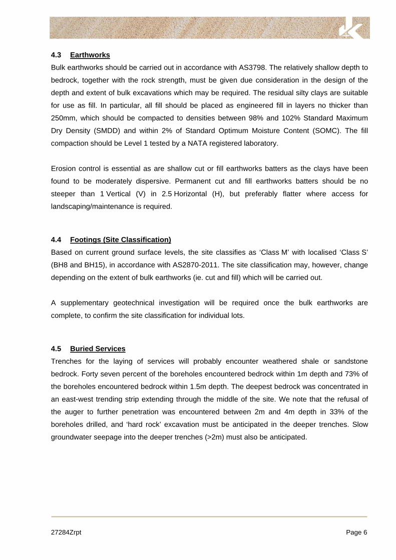
4.3 Earthworks Bulk earthworks should be carried out in accordance with AS3798. The relatively shallow depth to
bedrock, together with the rock strength, must be given due consideration in the design of the
depth and extent of bulk excavations which may be required. The residual silty clays are suitable
for use as fill. In particular, all fill should be placed as engineered fill in layers no thicker than
250mm, which should be compacted to densities between 98% and 102% Standard Maximum
Dry Density (SMDD) and within 2% of Standard Optimum Moisture Content (SOMC). The fill
compaction should be Level 1 tested by a NATA registered laboratory.
Erosion control is essential as are shallow cut or fill earthworks batters as the clays have been
found to be moderately dispersive. Permanent cut and fill earthworks batters should be no
steeper than 1 Vertical (V) in 2.5 Horizontal (H), but preferably flatter where access for
landscaping/maintenance is required.
4.4 Footings (Site Classification) Based on current ground surface levels, the site classifies as ‘Class M’ with localised ‘Class S’
(BH8 and BH15), in accordance with AS2870-2011. The site classification may, however, change
depending on the extent of bulk earthworks (ie. cut and fill) which will be carried out.
A supplementary geotechnical investigation will be required once the bulk earthworks are
complete, to confirm the site classification for individual lots.
4.5 Buried Services Trenches for the laying of services will probably encounter weathered shale or sandstone
bedrock. Forty seven percent of the boreholes encountered bedrock within 1m depth and 73% of
the boreholes encountered bedrock within 1.5m depth. The deepest bedrock was concentrated in
an east-west trending strip extending through the middle of the site. We note that the refusal of
the auger to further penetration was encountered between 2m and 4m depth in 33% of the
boreholes drilled, and ‘hard rock’ excavation must be anticipated in the deeper trenches. Slow
groundwater seepage into the deeper trenches (>2m) must also be anticipated.

27284Zrpt Page 7
4.6 Pavements The design of pavements will depend on subgrade preparation, subgrade drainage, the nature
and composition of any new fill imported to the site, as well as vehicle loadings and use.
Provided the subgrade is adequately prepared (ie. the width of the roadway is boxed out and the
exposed subgrade at design level is successfully proof-rolled), flexible pavements may be
tentatively designed for a soaked CBR value of 3%.
A supplementary geotechnical investigation along the proposed pavements will be required once
the bulk earthworks are complete, to confirm the design CBR value.
4.7 Further Geotechnical Investigation A further geotechnical investigation must be carried out once the bulk earthworks have been
completed to confirm the site classification (AS2870) for individual lots and the CBR design
value(s) for the proposed pavements.
The scope of the further geotechnical investigation can only be determined once the extent and
depth of bulk earthworks have been established and the lot layouts finalised.
5 GENERAL COMMENTS The comments and recommendations which follow should be considered as preliminary and
general in nature and are intended to aid the planning and initial design process. More extensive
geotechnical investigations will be required for detailed design and construction documentation.
Occasionally, the subsurface conditions between the completed boreholes may be found to be
different (or may be interpreted to be different) from those expected. Variation can also occur
with groundwater conditions, especially after climatic changes. If such differences appear to
exist, we recommend that you immediately contact this office.
A waste classification will need to be assigned to any soil excavated from the site prior to offsite
disposal. Subject to the appropriate testing, material can be classified as Virgin Excavated
Natural Material (VENM), General Solid, Restricted Solid or Hazardous Waste. If the natural soil
has been stockpiled, classification of this soil as Excavated Natural Material (ENM) can also be
undertaken, if requested. However, the criteria for ENM are more stringent and the cost
associated with attempting to meet these criteria may be significant. Analysis takes seven to

27284Zrpt Page 8
10 working days to complete, therefore, an adequate allowance should be included in the
construction program unless testing is completed prior to construction. If contamination is
encountered, then substantial further testing (and associated delays) should be expected.
We strongly recommend that this issue is addressed prior to the commencement of excavation on
site.
This report has been prepared for the particular project described and no responsibility is
accepted for the use of any part of this report in any other context or for any other purpose.
If there is any change in the proposed development described in this report then all
recommendations should be reviewed. Copyright in this report is the property of JK Geotechnics.
We have used a degree of care, skill and diligence normally exercised by consulting engineers in
similar circumstances and locality. No other warranty expressed or implied is made or intended.
Subject to payment of all fees due for the investigation, the client alone shall have a licence to
use this report. The report shall not be reproduced except in full.


0
1
2
3
4
5
6
7
DRY ONCOMPLET-
ION& AFTER20 HRS
ON18-3-14
N = 287,12,16
CH
CL
-
-
FILL: Silty clay topsoil, low plasticity,dark brown, trace of root fibres.SILTY CLAY: high plasticity, brown,trace of root fibres.SILTY CLAY: medium plasticity, lightgrey, with fine to medium grainedironstone gravel.
SHALE: dark grey and red brown.
as above,but with clay seams.
INTERBEDDED SHALE ANDSANDSTONE: fine grained, dark greyand red brown.
END OF BOREHOLE AT 3.5m
MC<PLMC<PL
DW
(H)
M
H
GRASS COVER
TOO FRIABLE FORHP TESTING
MODERATE 'TC' BITRESISTANCE
BANDED MODERATERESISTANCE
HIGH RESISTANCE
'TC' BIT REFUSAL
CLASS 18 PVCSTANDPIPEINSTALLED TO 3.5mDEPTH. MACHINESLOTTED BETWEEN3.5m AND 0.5m,CASING 0.5m TOSURFACE,BACKFILLED WITH2mm SAND FILTERSAND 3.5m TO 0.5m,BENTONITE SEAL0.5m TO 0.2m,METAL MONUMENTCONCRETED ATSURFACE
JK GeotechnicsGEOTECHNICAL AND ENVIRONMENTAL ENGINEERS
BOREHOLE LOGBorehole No.
JK1
Client: SOUWEST DEVELOPMENT
Project: PROPOSED SUB-DIVISION
Location: OFF STATION STREET, MENANGLE, NSW
Job No. 27284Z Method: SPIRAL AUGERJK350
R.L. Surface: » 79.0m
Date: 6-3-14 Datum: ASSUMED
Logged/Checked by: D.S./A.Z.
Gro
undw
ate
rR
ecord
ES
SA
MP
LE
SU
50
DB
DS
Fie
ld T
ests
Depth
(m
)
Gra
phic
Log
Unifie
dC
lassific
ation
DESCRIPTION
Mois
ture
Conditio
n/
Weath
eri
ng
Str
ength
/R
el. D
ensity
Hand
Penetr
om
ete
rR
eadin
gs (
kP
a.)
Remarks
CO
PY
RIG
HT
1/1
0
1
2
3
4
5
6
7
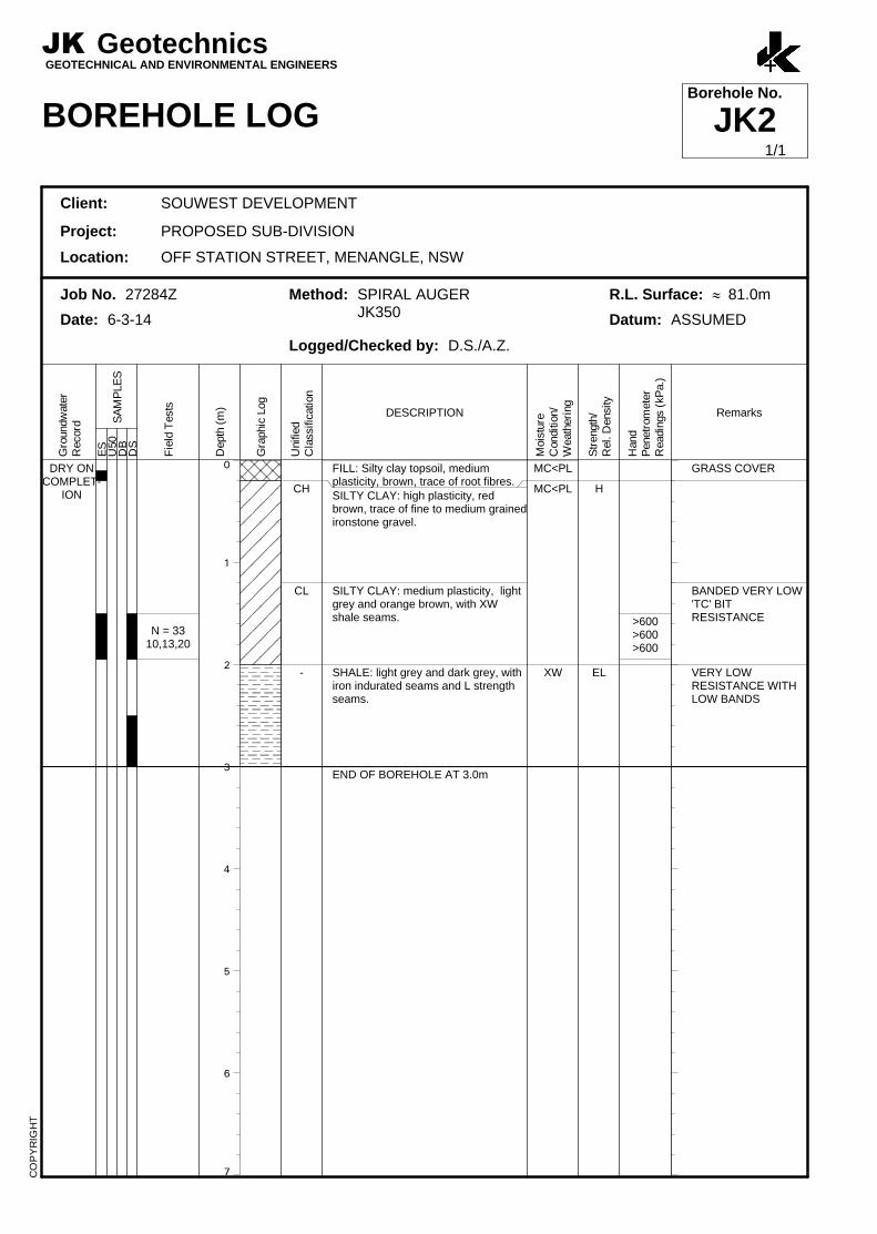
DRY ONCOMPLET-
ION
N = 3310,13,20
CH
CL
-
FILL: Silty clay topsoil, mediumplasticity, brown, trace of root fibres.SILTY CLAY: high plasticity, redbrown, trace of fine to medium grainedironstone gravel.
SILTY CLAY: medium plasticity, lightgrey and orange brown, with XWshale seams.
SHALE: light grey and dark grey, withiron indurated seams and L strengthseams.
END OF BOREHOLE AT 3.0m
MC<PL
MC<PL
XW
H
EL
>600>600>600
GRASS COVER
BANDED VERY LOW'TC' BITRESISTANCE
VERY LOWRESISTANCE WITHLOW BANDS
JK GeotechnicsGEOTECHNICAL AND ENVIRONMENTAL ENGINEERS
BOREHOLE LOGBorehole No.
JK2
Client: SOUWEST DEVELOPMENT
Project: PROPOSED SUB-DIVISION
Location: OFF STATION STREET, MENANGLE, NSW
Job No. 27284Z Method: SPIRAL AUGERJK350
R.L. Surface: » 81.0m
Date: 6-3-14 Datum: ASSUMED
Logged/Checked by: D.S./A.Z.
Gro
undw
ate
rR
ecord
ES
SA
MP
LE
SU
50
DB
DS
Fie
ld T
ests
Depth
(m
)
Gra
phic
Log
Unifie
dC
lassific
ation
DESCRIPTION
Mois
ture
Conditio
n/
Weath
eri
ng
Str
ength
/R
el. D
ensity
Hand
Penetr
om
ete
rR
eadin
gs (
kP
a.)
Remarks
CO
PY
RIG
HT
1/1

0
1
2
3
4
5
6
7
DRY ONCOMPLET-
ION
N = 328,12,20
CH
-
FILL: Silty clay, medium plasticity,brown, trace of root fibres.SILTY CLAY: high plasticity, orangebrown, trace of root fibres.SILTY CLAY: high plasticity, lightgrey, with fine to medium grainedironstone gravel.
SHALE: brown and red brown.
END OF BOREHOLE AT 3.0m
MC<PL
MC<PL
DW
(H)
H
M
>600>600>600
GRASS COVER
MODERATERESISTANCE
JK GeotechnicsGEOTECHNICAL AND ENVIRONMENTAL ENGINEERS
BOREHOLE LOGBorehole No.
JK3
Client: SOUWEST DEVELOPMENT
Project: PROPOSED SUB-DIVISION
Location: OFF STATION STREET, MENANGLE, NSW
Job No. 27284Z Method: SPIRAL AUGERJK350
R.L. Surface: » 81.5m
Date: 6-3-14 Datum: ASSUMED
Logged/Checked by: D.S./A.Z.
Gro
undw
ate
rR
ecord
ES
SA
MP
LE
SU
50
DB
DS
Fie
ld T
ests
Depth
(m
)
Gra
phic
Log
Unifie
dC
lassific
ation
DESCRIPTION
Mois
ture
Conditio
n/
Weath
eri
ng
Str
ength
/R
el. D
ensity
Hand
Penetr
om
ete
rR
eadin
gs (
kP
a.)
Remarks
CO
PY
RIG
HT
1/1

0
1
2
3
4
5
6
7
DRY ONCOMPLET-
ION
N = 209,10,10
N = 298,16,13
CH
-
FILL: Silty clay topsoil, mediumplasticity, red brown, trace of fine tomedium grained ironstone gravel androot fibres.SILTY CLAY: high plasticity, redbrown and light grey, with fine tocoarse grained ironstone gravel.
as above,but light grey.
SHALE: dark grey.
END OF BOREHOLE AT 3.0m
MC<PL
MC<PL
DW
H
M
>600>600>600
>600>600>600
GRASS COVER
LOW 'TC' BITRESISTANCE
JK GeotechnicsGEOTECHNICAL AND ENVIRONMENTAL ENGINEERS
BOREHOLE LOGBorehole No.
JK4
Client: SOUWEST DEVELOPMENT
Project: PROPOSED SUB-DIVISION
Location: OFF STATION STREET, MENANGLE, NSW
Job No. 27284Z Method: SPIRAL AUGERJK350
R.L. Surface: » 86.2m
Date: 6-3-14 Datum: ASSUMED
Logged/Checked by: D.S./A.Z.
Gro
undw
ate
rR
ecord
ES
SA
MP
LE
SU
50
DB
DS
Fie
ld T
ests
Depth
(m
)
Gra
phic
Log
Unifie
dC
lassific
ation
DESCRIPTION
Mois
ture
Conditio
n/
Weath
eri
ng
Str
ength
/R
el. D
ensity
Hand
Penetr
om
ete
rR
eadin
gs (
kP
a.)
Remarks
CO
PY
RIG
HT
1/1
0
1
2
3
4
5
6
7
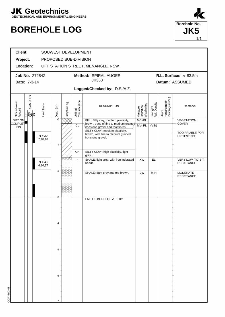
DRY ONCOMPLET-
ION
N = 207,10,10
N = 434,16,27
CL
CH
-
FILL: Silty clay, medium plasticity,brown, trace of fine to medium grainedironstone gravel and root fibres.SILTY CLAY: medium plasticity,brown, with fine to medium grainedironstone gravel.
SILTY CLAY: high plasticity, lightgrey.
SHALE: light grey, with iron induratedbands.
SHALE: dark grey and red brown.
END OF BORHOLE AT 3.0m
MC<PL
MV<PL
XW
DW
(VSt)
EL
M-H
VEGETATIONCOVER
TOO FRIABLE FORHP TESTING
VERY LOW 'TC' BITRESISTANCE
MODERATERESISTANCE
JK GeotechnicsGEOTECHNICAL AND ENVIRONMENTAL ENGINEERS
BOREHOLE LOGBorehole No.
JK5
Client: SOUWEST DEVELOPMENT
Project: PROPOSED SUB-DIVISION
Location: OFF STATION STREET, MENANGLE, NSW
Job No. 27284Z Method: SPIRAL AUGERJK350
R.L. Surface: » 83.5m
Date: 7-3-14 Datum: ASSUMED
Logged/Checked by: D.S./A.Z.
Gro
undw
ate
rR
ecord
ES
SA
MP
LE
SU
50
DB
DS
Fie
ld T
ests
Depth
(m
)
Gra
phic
Log
Unifie
dC
lassific
ation
DESCRIPTION
Mois
ture
Conditio
n/
Weath
eri
ng
Str
ength
/R
el. D
ensity
Hand
Penetr
om
ete
rR
eadin
gs (
kP
a.)
Remarks
CO
PY
RIG
HT
1/1

0
1
2
3
4
5
6
7
DRY ONCOMPLET-
ION
N = 184,8,10
N = 2810,15,13
CH
CL
-
FILL: Silty gravel, fine to coarsegrained shale, dark grey, trace of clayfines and root fibres.
SILTY CLAY: high plasticity, orangebrown mottled light grey, with fine tomedium grained ironstone gravel,trace of root fibres.
SILTY CLAY: low plasticity, light greyand orange brown, with L strengthshale seams.
SHALE: dark grey and red brown.
END OF BOREHOLE AT 3.0m
D
MC<PL
DW
H
L-M
550550
>600
>600>600>600
GRASS COVER
BANDED VERY LOW'TC' BITRESISTANCE
LOW TO MODERATERESISTANCE
JK GeotechnicsGEOTECHNICAL AND ENVIRONMENTAL ENGINEERS
BOREHOLE LOGBorehole No.
JK6
Client: SOUWEST DEVELOPMENT
Project: PROPOSED SUB-DIVISION
Location: OFF STATION STREET, MENANGLE, NSW
Job No. 27284Z Method: SPIRAL AUGERJK350
R.L. Surface: » 80.0m
Date: 6-3-14 Datum: ASSUMED
Logged/Checked by: D.S./A.Z.
Gro
undw
ate
rR
ecord
ES
SA
MP
LE
SU
50
DB
DS
Fie
ld T
ests
Depth
(m
)
Gra
phic
Log
Unifie
dC
lassific
ation
DESCRIPTION
Mois
ture
Conditio
n/
Weath
eri
ng
Str
ength
/R
el. D
ensity
Hand
Penetr
om
ete
rR
eadin
gs (
kP
a.)
Remarks
CO
PY
RIG
HT
1/1

0
1
2
3
4
5
6
7
DRY ONCOMPLET-
ION
N = 267,11,15
CL
-
FILL: Silty clay topsoil, mediumplasticity, brown, trace of root fibres.SILTY CLAY: medium plasticity, lightgrey and orange brown, trace of rootfibres.
SHALE: brown and red brown.
SHALE: dark grey, brown and redbrown.
END OF BOREHOLE AT 3.0m
MC<PL
MC<PL
DW
H
L-M
M-H
>600>600>600
GRASS COVER
LOW TO MODERATE'TC' BITRESISTANCE
MODERATE TO HIGHRESISTANCE
JK GeotechnicsGEOTECHNICAL AND ENVIRONMENTAL ENGINEERS
BOREHOLE LOGBorehole No.
JK7
Client: SOUWEST DEVELOPMENT
Project: PROPOSED SUB-DIVISION
Location: OFF STATION STREET, MENANGLE, NSW
Job No. 27284Z Method: SPIRAL AUGERJK350
R.L. Surface: » 80.0m
Date: 6-3-14 Datum: ASSUMED
Logged/Checked by: D.S./A.Z.
Gro
undw
ate
rR
ecord
ES
SA
MP
LE
SU
50
DB
DS
Fie
ld T
ests
Depth
(m
)
Gra
phic
Log
Unifie
dC
lassific
ation
DESCRIPTION
Mois
ture
Conditio
n/
Weath
eri
ng
Str
ength
/R
el. D
ensity
Hand
Penetr
om
ete
rR
eadin
gs (
kP
a.)
Remarks
CO
PY
RIG
HT
1/1

0
1
2
3
4
5
6
7
DRY ONCOMPLET-
ION,AFTER
22.5HRS &
ON18-3-14
N > 1612,16/100mm
REFUSAL
CL
-
FILL: Silty clay, medium plasticity,dark brown, trace of fine to mediumgrained ironstone gravel and rootfibres.SILTY CLAY: medium plasticity,orange brown.SHALE: light grey and dark grey.
SHALE: dark grey and brown.
SHALE: dark grey.
END OF BOREHOLE AT 4.0m
MC<PL
MC<PL
XW-DW
SW
EL-VL
M
H
GRASS COVER
VERY LOW 'TC' BITRESISTANCE
MODERATERESISTANCE
HIGH RESISTANCE
'TC' BIT REFUSAL
CLASS 18 PVCSTANDPIPEINSTALLED TO 4mDEPTH. MACHINESLOTTED BETWEEN1m AND 4m, CASINGTO SURFACE,BACKFILLED WITH2mm SAND FILTERSAND 4m TO 0.5m,BENTONITE SEAL0.5m TO 0.2m,METAL MONUMENTCONCRETED ATSURFACE
JK GeotechnicsGEOTECHNICAL AND ENVIRONMENTAL ENGINEERS
BOREHOLE LOGBorehole No.
JK8
Client: SOUWEST DEVELOPMENT
Project: PROPOSED SUB-DIVISION
Location: OFF STATION STREET, MENANGLE, NSW
Job No. 27284Z Method: SPIRAL AUGERJK350
R.L. Surface: » 84.0m
Date: 6-3-14 Datum: ASSUMED
Logged/Checked by: D.S./A.Z.
Gro
undw
ate
rR
ecord
ES
SA
MP
LE
SU
50
DB
DS
Fie
ld T
ests
Depth
(m
)
Gra
phic
Log
Unifie
dC
lassific
ation
DESCRIPTION
Mois
ture
Conditio
n/
Weath
eri
ng
Str
ength
/R
el. D
ensity
Hand
Penetr
om
ete
rR
eadin
gs (
kP
a.)
Remarks
CO
PY
RIG
HT
1/1
0
1
2
3
4
5
6
7
DRY ONCOMPLET-
ION
ON18-3-14
N = 167,8,8
CL
-
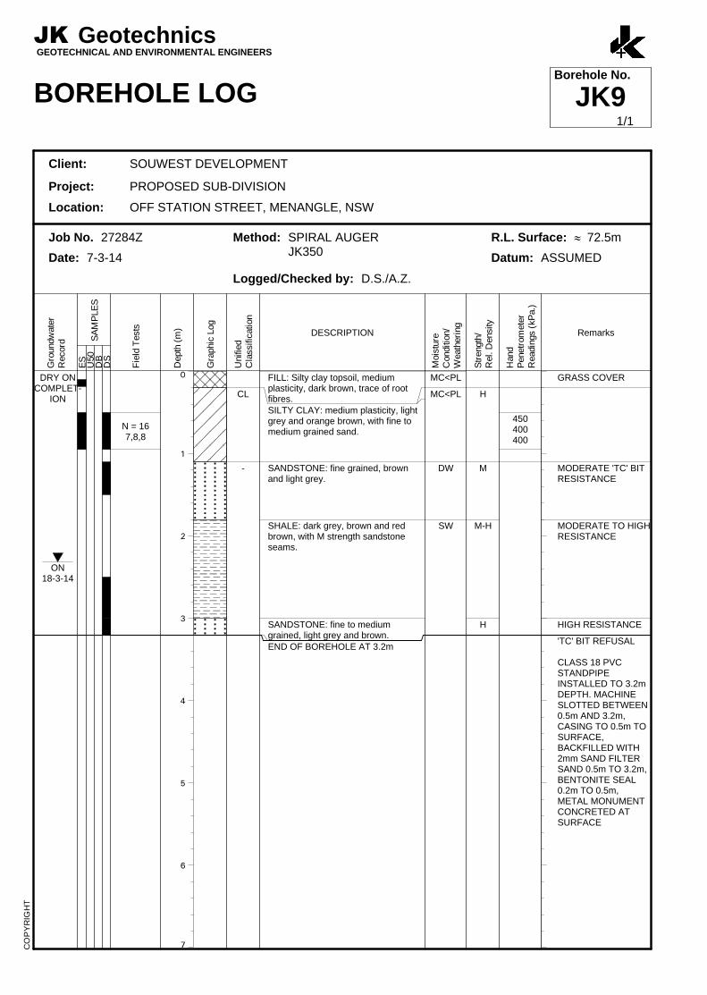
FILL: Silty clay topsoil, mediumplasticity, dark brown, trace of rootfibres.SILTY CLAY: medium plasticity, lightgrey and orange brown, with fine tomedium grained sand.
SANDSTONE: fine grained, brownand light grey.
SHALE: dark grey, brown and redbrown, with M strength sandstoneseams.
SANDSTONE: fine to mediumgrained, light grey and brown.END OF BOREHOLE AT 3.2m
MC<PL
MC<PL
DW
SW
H
M
M-H
H
450400400
GRASS COVER
MODERATE 'TC' BITRESISTANCE
MODERATE TO HIGHRESISTANCE
HIGH RESISTANCE
'TC' BIT REFUSAL
CLASS 18 PVCSTANDPIPEINSTALLED TO 3.2mDEPTH. MACHINESLOTTED BETWEEN0.5m AND 3.2m,CASING TO 0.5m TOSURFACE,BACKFILLED WITH2mm SAND FILTERSAND 0.5m TO 3.2m,BENTONITE SEAL0.2m TO 0.5m,METAL MONUMENTCONCRETED ATSURFACE
JK GeotechnicsGEOTECHNICAL AND ENVIRONMENTAL ENGINEERS
BOREHOLE LOGBorehole No.
JK9
Client: SOUWEST DEVELOPMENT
Project: PROPOSED SUB-DIVISION
Location: OFF STATION STREET, MENANGLE, NSW
Job No. 27284Z Method: SPIRAL AUGERJK350
R.L. Surface: » 72.5m
Date: 7-3-14 Datum: ASSUMED
Logged/Checked by: D.S./A.Z.
Gro
undw
ate
rR
ecord
ES
SA
MP
LE
SU
50
DB
DS
Fie
ld T
ests
Depth
(m
)
Gra
phic
Log
Unifie
dC
lassific
ation
DESCRIPTION
Mois
ture
Conditio
n/
Weath
eri
ng
Str
ength
/R
el. D
ensity
Hand
Penetr
om
ete
rR
eadin
gs (
kP
a.)
Remarks
CO
PY
RIG
HT
1/1

0
1
2
3
4
5
6
7
DRY ONCOMPLET-
ION
N > 2011,20/150mm
REFUSAL
CL
-
FILL: Silty clay topsoil, mediumplasticity, brown, trace of fine tomedium grained ironstone gravel androot fibres.SILTY CLAY: low plasticity, light greyand orange brown, trace of finegrained sand.SANDSTONE: fine grained, light greyand orange brown.
SANDSTONE: fine grained, light grey.
END OF BOREHOLE AT 2.0m
MC<PL
MC<PL
DW
SW
H
M-H
H
>600>600>600
GRASS COVER
MODERATE'TC' BITRESISTANCE
HIGH RESISTANCE
'TC' BIT REFUSAL
JK GeotechnicsGEOTECHNICAL AND ENVIRONMENTAL ENGINEERS
BOREHOLE LOGBorehole No.
JK10
Client: SOUWEST DEVELOPMENT
Project: PROPOSED SUB-DIVISION
Location: OFF STATION STREET, MENANGLE, NSW
Job No. 27284Z Method: SPIRAL AUGERJK350
R.L. Surface: » 74.5m
Date: 7-3-14 Datum: ASSUMED
Logged/Checked by: D.S./A.Z.
Gro
undw
ate
rR
ecord
ES
SA
MP
LE
SU
50
DB
DS
Fie
ld T
ests
Depth
(m
)
Gra
phic
Log
Unifie
dC
lassific
ation
DESCRIPTION
Mois
ture
Conditio
n/
Weath
eri
ng
Str
ength
/R
el. D
ensity
Hand
Penetr
om
ete
rR
eadin
gs (
kP
a.)
Remarks
CO
PY
RIG
HT
1/1

0
1
2
3
4
5
6
7
DRY ONCOMPLET-
ION
N > 228,22/
100mmREFUSAL
CL
-
FILL: Silty clay, low plasticity, brown,with fine to medium grained ironstonegravel, trace of fine grained sand androot fibres.SILTY CLAY: medium plasticity,orange brown and light grey, with fineto medium grained ironstone gravel,trace of root fibres.SHALE: dark grey and brown.
SANDSTONE: fine grained, light grey.
END OF BOREHOLE AT 3.0m
MC<PL
MC<PL
DW
SW
H
L-M
H
>600>600>600
GRASS COVER
LOW TO MODERATE'TC' BITRESISTANCE
HIGH RESISTANCE
JK GeotechnicsGEOTECHNICAL AND ENVIRONMENTAL ENGINEERS
BOREHOLE LOGBorehole No.
JK11
Client: SOUWEST DEVELOPMENT
Project: PROPOSED SUB-DIVISION
Location: OFF STATION STREET, MENANGLE, NSW
Job No. 27284Z Method: SPIRAL AUGERJK350
R.L. Surface: » 80.0m
Date: 7-3-14 Datum: ASSUMED
Logged/Checked by: D.S./A.Z.
Gro
undw
ate
rR
ecord
ES
SA
MP
LE
SU
50
DB
DS
Fie
ld T
ests
Depth
(m
)
Gra
phic
Log
Unifie
dC
lassific
ation
DESCRIPTION
Mois
ture
Conditio
n/
Weath
eri
ng
Str
ength
/R
el. D
ensity
Hand
Penetr
om
ete
rR
eadin
gs (
kP
a.)
Remarks
CO
PY
RIG
HT
1/1
0
1
2
3
4
5
6
7
DRY ONCOMPLET-
ION
N = 245,10,14
N = 308,15,15
CH
-
FILL: Silty clay topsoil, mediumplasticity, brown, trace of root fibres.SILTY CLAY: high plasticity, redbrown and light grey, trace of fine tomedium grained ironstone gravel androot fibres.
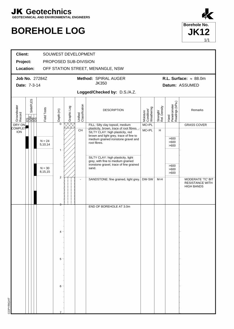
SILTY CLAY: high plasticity, lightgrey, with fine to medium grainedironstone gravel, trace of fine grainedsand.
SANDSTONE: fine grained, light grey.
END OF BOREHOLE AT 3.0m
MC<PL
MC<PL
DW-SW
H
M-H
>600>600>600
>600>600>600
GRASS COVER
MODERATE 'TC' BITRESISTANCE WITHHIGH BANDS
JK GeotechnicsGEOTECHNICAL AND ENVIRONMENTAL ENGINEERS
BOREHOLE LOGBorehole No.
JK12
Client: SOUWEST DEVELOPMENT
Project: PROPOSED SUB-DIVISION
Location: OFF STATION STREET, MENANGLE, NSW
Job No. 27284Z Method: SPIRAL AUGERJK350
R.L. Surface: » 88.0m
Date: 7-3-14 Datum: ASSUMED
Logged/Checked by: D.S./A.Z.
Gro
undw
ate
rR
ecord
ES
SA
MP
LE
SU
50
DB
DS
Fie
ld T
ests
Depth
(m
)
Gra
phic
Log
Unifie
dC
lassific
ation
DESCRIPTION
Mois
ture
Conditio
n/
Weath
eri
ng
Str
ength
/R
el. D
ensity
Hand
Penetr
om
ete
rR
eadin
gs (
kP
a.)
Remarks
CO
PY
RIG
HT
1/1

0
1
2
3
4
5
6
7
DRY ONCOMPLET-
ION
N = 277,11,16
CH
-
FILL: Silty sandy clay, low plasticity,brown, trace of fine to medium grainedironstone gravel and root fibres.SILTY CLAY: high plasticity, light greyand red brown, with fine to mediumgrained ironstone gravel.
SHALE: dark grey and red brown.
END OF BOREHOLE AT 3.0m
MC<PL
MC<PL
DW
H
M
>600>600>600
GRASS COVER
LOW TO MODERATE'TC' BITRESISTANCE
JK GeotechnicsGEOTECHNICAL AND ENVIRONMENTAL ENGINEERS
BOREHOLE LOGBorehole No.
JK13
Client: SOUWEST DEVELOPMENT
Project: PROPOSED SUB-DIVISION
Location: OFF STATION STREET, MENANGLE, NSW
Job No. 27284Z Method: SPIRAL AUGERJK350
R.L. Surface: » 84.0m
Date: 7-3-14 Datum: ASSUMED
Logged/Checked by: D.S./A.Z.
Gro
undw
ate
rR
ecord
ES
SA
MP
LE
SU
50
DB
DS
Fie
ld T
ests
Depth
(m
)
Gra
phic
Log
Unifie
dC
lassific
ation
DESCRIPTION
Mois
ture
Conditio
n/
Weath
eri
ng
Str
ength
/R
el. D
ensity
Hand
Penetr
om
ete
rR
eadin
gs (
kP
a.)
Remarks
CO
PY
RIG
HT
1/1
0
1
2
3
4
5
6
7
DRY ONCOMPLET-
ION
N > 208,20/
150mmREFUSAL
CL
-
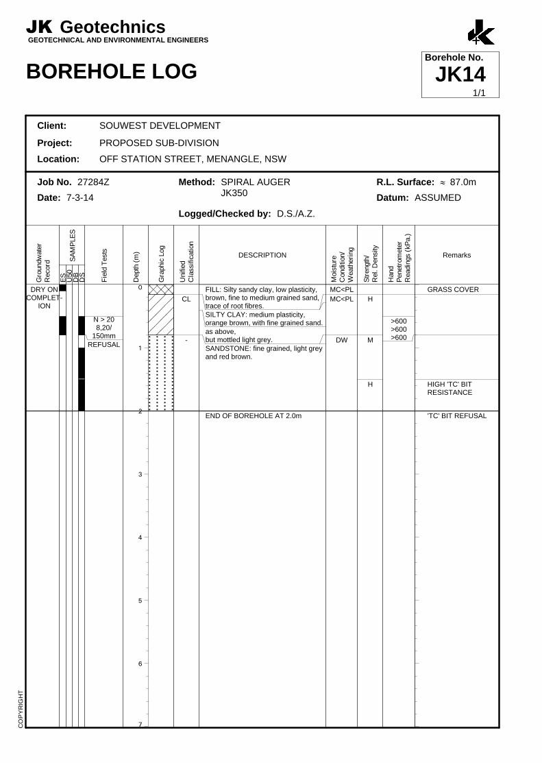
FILL: Silty sandy clay, low plasticity,brown, fine to medium grained sand,trace of root fibres.SILTY CLAY: medium plasticity,orange brown, with fine grained sand.as above,but mottled light grey.SANDSTONE: fine grained, light greyand red brown.
END OF BOREHOLE AT 2.0m
MC<PL
MC<PL
DW
H
M
H
>600>600>600
GRASS COVER
HIGH 'TC' BITRESISTANCE
'TC' BIT REFUSAL
JK GeotechnicsGEOTECHNICAL AND ENVIRONMENTAL ENGINEERS
BOREHOLE LOGBorehole No.
JK14
Client: SOUWEST DEVELOPMENT
Project: PROPOSED SUB-DIVISION
Location: OFF STATION STREET, MENANGLE, NSW
Job No. 27284Z Method: SPIRAL AUGERJK350
R.L. Surface: » 87.0m
Date: 7-3-14 Datum: ASSUMED
Logged/Checked by: D.S./A.Z.
Gro
undw
ate
rR
ecord
ES
SA
MP
LE
SU
50
DB
DS
Fie
ld T
ests
Depth
(m
)
Gra
phic
Log
Unifie
dC
lassific
ation
DESCRIPTION
Mois
ture
Conditio
n/
Weath
eri
ng
Str
ength
/R
el. D
ensity
Hand
Penetr
om
ete
rR
eadin
gs (
kP
a.)
Remarks
CO
PY
RIG
HT
1/1

0
1
2
3
4
5
6
7
DRY ONCOMPLET-
ION
ON18-3-14
CL
-
FILL: Silty clay, medium plasticity,brown, trace of root fibres.SILTY CLAY: low plasticity, light grey,with fine to medium grained ironstonegravel, trace of root fibres.SHALE: dark grey and red brown.
END OF BOREHOLE AT 6.0m
MC<PLMC<PL
DW
(H)
L-M
M
GRASS COVER
LOW TO MODERATE'TC' BITRESISTANCE
MODERATERESISTANCE
CLASS 18 PVCSTANDPIPEINSTALLED TO 3. 5mDEPTH. MACHINESLOTTED BETWEEN6m AND 1m, CASING1m TO SURFACE,BACKFILLED WITH2mm SAND FILTERSAND 6.0m TO 0.5m,BENTONITE SEAL0.5m TO 0.2m,METAL MONUMENTCONCRETED ATSURFACE
JK GeotechnicsGEOTECHNICAL AND ENVIRONMENTAL ENGINEERS
BOREHOLE LOGBorehole No.
JK15
Client: SOUWEST DEVELOPMENT
Project: PROPOSED SUB-DIVISION
Location: OFF STATION STREET, MENANGLE, NSW
Job No. 27284Z Method: SPIRAL AUGERJK350
R.L. Surface: » 87.0m
Date: 7-3-14 Datum: ASSUMED
Logged/Checked by: D.S./A.Z.
Gro
undw
ate
rR
ecord
ES
SA
MP
LE
SU
50
DB
DS
Fie
ld T
ests
Depth
(m
)
Gra
phic
Log
Unifie
dC
lassific
ation
DESCRIPTION
Mois
ture
Conditio
n/
Weath
eri
ng
Str
ength
/R
el. D
ensity
Hand
Penetr
om
ete
rR
eadin
gs (
kP
a.)
Remarks
CO
PY
RIG
HT
1/1

NOTES:Figure 2 has been recreated from the SiteConcept Plan prepared by Elton Consulting
The borehole locations presented on thisplan have been established from sitemeasurements only and should not beconstrued as survey points.
Reference should be made to the reporttext for a full understanding of this plan.
LEGEND:
Borehole location and number
Groundwater monitoring well location
JK1
HU
ME
HIG
HW
AY
STATION STREET
ME
NA
NG
LE
RO
AD
NEPEANRIV
ER
JK1
JK2
JK3 JK4
JK5
JK8
JK6
JK7
JK9
JK10
JK11
JK13
JK12
JK14
JK15

Jeffery & Katauskas Pty Ltd, trading as JK Geotechnics ABN 17 003 550 801
JKG Report Explanation Notes Rev2 May 2013 Page 1 of 4
REPORT EXPLANATION NOTES
INTRODUCTION
These notes have been provided to amplify the geotechnicalreport in regard to classification methods, field proceduresand certain matters relating to the Comments andRecommendations section. Not all notes are necessarilyrelevant to all reports.
The ground is a product of continuing natural and man-made processes and therefore exhibits a variety ofcharacteristics and properties which vary from place to placeand can change with time. Geotechnical engineeringinvolves gathering and assimilating limited facts about thesecharacteristics and properties in order to understand orpredict the behaviour of the ground on a particular site undercertain conditions. This report may contain such factsobtained by inspection, excavation, probing, sampling,testing or other means of investigation. If so, they aredirectly relevant only to the ground at the place where andtime when the investigation was carried out.
DESCRIPTION AND CLASSIFICATION METHODS
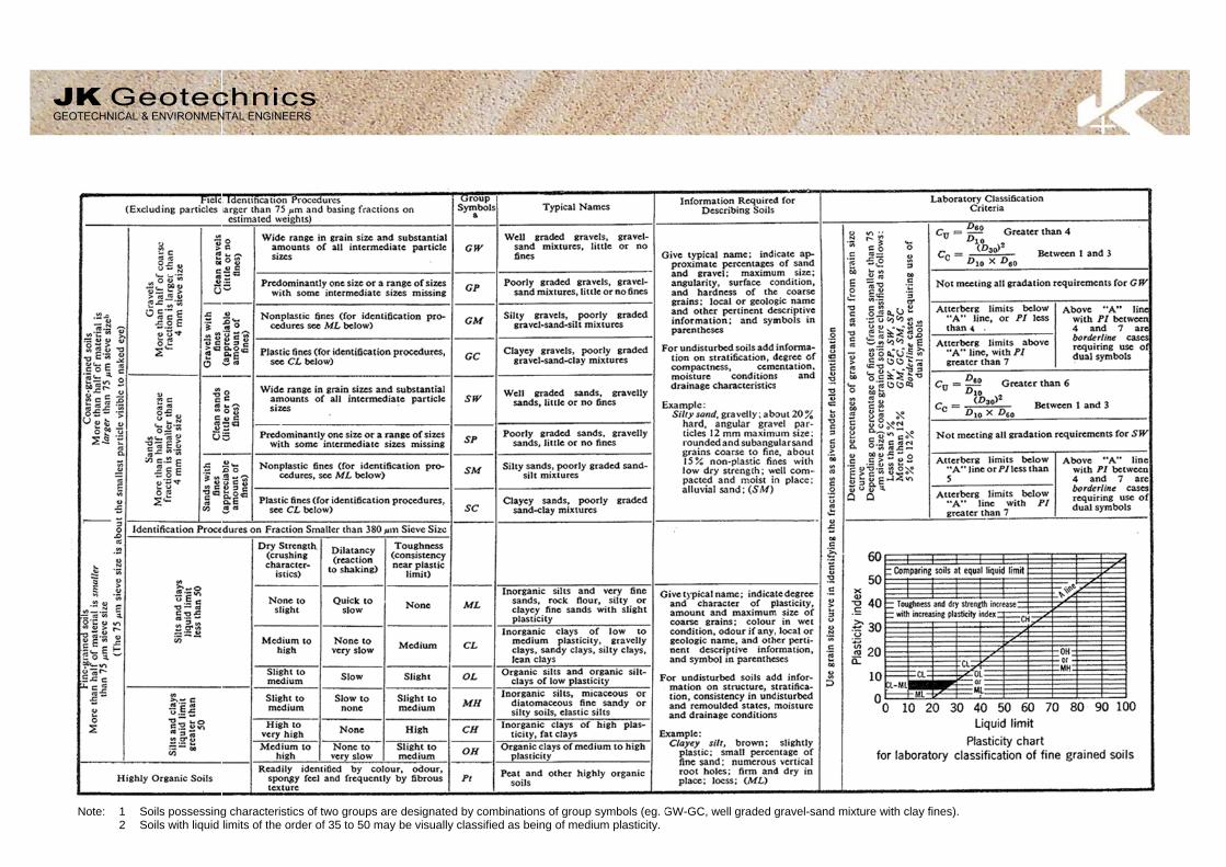
The methods of description and classification of soils androcks used in this report are based on Australian Standard1726, the SAA Site Investigation Code. In general,descriptions cover the following properties – soil or rock type,colour, structure, strength or density, and inclusions.Identification and classification of soil and rock involvesjudgement and the Company infers accuracy only to theextent that is common in current geotechnical practice.
Soil types are described according to the predominatingparticle size and behaviour as set out in the attached UnifiedSoil Classification Table qualified by the grading of otherparticles present (e.g. sandy clay) as set out below:
Soil Classification Particle Size
Clay
Silt
Sand
Gravel
less than 0.002mm
0.002 to 0.075mm
0.075 to 2mm
2 to 60mm
Non-cohesive soils are classified on the basis of relativedensity, generally from the results of Standard PenetrationTest (SPT) as below:
Relative DensitySPT ‘N’ Value(blows/300mm)
Very loose
Loose
Medium dense
Dense
Very Dense
less than 4
4 – 10
10 – 30
30 – 50
greater than 50
Cohesive soils are classified on the basis of strength(consistency) either by use of hand penetrometer, laboratorytesting or engineering examination. The strength terms aredefined as follows.
ClassificationUnconfined CompressiveStrength kPa
Very Soft
Soft
Firm
Stiff
Very Stiff
Hard
Friable
less than 25
25 – 50
50 – 100
100 – 200
200 – 400
Greater than 400
Strength not attainable
– soil crumbles
Rock types are classified by their geological names,together with descriptive terms regarding weathering,strength, defects, etc. Where relevant, further informationregarding rock classification is given in the text of the report.In the Sydney Basin, ‘Shale’ is used to describe thinlybedded to laminated siltstone.
SAMPLING
Sampling is carried out during drilling or from otherexcavations to allow engineering examination (andlaboratory testing where required) of the soil or rock.
Disturbed samples taken during drilling provide informationon plasticity, grain size, colour, moisture content, minorconstituents and, depending upon the degree of disturbance,some information on strength and structure. Bulk samplesare similar but of greater volume required for some testprocedures.
Undisturbed samples are taken by pushing a thin-walledsample tube, usually 50mm diameter (known as a U50), intothe soil and withdrawing it with a sample of the soilcontained in a relatively undisturbed state. Such samplesyield information on structure and strength, and arenecessary for laboratory determination of shear strengthand compressibility. Undisturbed sampling is generallyeffective only in cohesive soils.
Details of the type and method of sampling used are givenon the attached logs.
INVESTIGATION METHODS
The following is a brief summary of investigation methodscurrently adopted by the Company and some comments ontheir use and application. All except test pits, hand augerdrilling and portable dynamic cone penetrometers requirethe use of a mechanical drilling rig which is commonlymounted on a truck chassis.
JK GeotechnicsGEOTECHNICAL & ENVIRONMENTAL ENGINEERS

JKG Report Explanation Notes Rev2 May 2013 Page 2 of 4
Test Pits: These are normally excavated with a backhoe ora tracked excavator, allowing close examination of the insitusoils if it is safe to descend into the pit. The depth ofpenetration is limited to about 3m for a backhoe and up to6m for an excavator. Limitations of test pits are the problemsassociated with disturbance and difficulty of reinstatementand the consequent effects on close-by structures. Caremust be taken if construction is to be carried out near test pitlocations to either properly recompact the backfill duringconstruction or to design and construct the structure so asnot to be adversely affected by poorly compacted backfill atthe test pit location.
Hand Auger Drilling: A borehole of 50mm to 100mmdiameter is advanced by manually operated equipment.Premature refusal of the hand augers can occur on a varietyof materials such as hard clay, gravel or ironstone, and doesnot necessarily indicate rock level.
Continuous Spiral Flight Augers: The borehole isadvanced using 75mm to 115mm diameter continuousspiral flight augers, which are withdrawn at intervals to allowsampling and insitu testing. This is a relatively economicalmeans of drilling in clays and in sands above the water table.Samples are returned to the surface by the flights or may becollected after withdrawal of the auger flights, but they canbe very disturbed and layers may become mixed.Information from the auger sampling (as distinct fromspecific sampling by SPTs or undisturbed samples) is ofrelatively lower reliability due to mixing or softening ofsamples by groundwater, or uncertainties as to the originaldepth of the samples. Augering below the groundwatertable is of even lesser reliability than augering above thewater table.
Rock Augering: Use can be made of a Tungsten Carbide(TC) bit for auger drilling into rock to indicate rock qualityand continuity by variation in drilling resistance and fromexamination of recovered rock fragments. This method ofinvestigation is quick and relatively inexpensive but providesonly an indication of the likely rock strength and predictedvalues may be in error by a strength order. Where rockstrengths may have a significant impact on constructionfeasibility or costs, then further investigation by means ofcored boreholes may be warranted.
Wash Boring: The borehole is usually advanced by arotary bit, with water being pumped down the drill rods andreturned up the annulus, carrying the drill cuttings.Only major changes in stratification can be determined fromthe cuttings, together with some information from “feel” andrate of penetration.
Mud Stabilised Drilling: Either Wash Boring orContinuous Core Drilling can use drilling mud as acirculating fluid to stabilise the borehole. The term ‘mud’encompasses a range of products ranging from bentonite topolymers such as Revert or Biogel. The mud tends to maskthe cuttings and reliable identification is only possible fromintermittent intact sampling (eg from SPT and U50 samples)or from rock coring, etc.
Continuous Core Drilling: A continuous core sample isobtained using a diamond tipped core barrel. Provided fullcore recovery is achieved (which is not always possible invery low strength rocks and granular soils), this techniqueprovides a very reliable (but relatively expensive) method ofinvestigation. In rocks, an NMLC triple tube core barrel,which gives a core of about 50mm diameter, is usually usedwith water flush. The length of core recovered is comparedto the length drilled and any length not recovered is shownas CORE LOSS. The location of losses are determined onsite by the supervising engineer; where the location isuncertain, the loss is placed at the top end of the drill run.
Standard Penetration Tests: Standard Penetration Tests(SPT) are used mainly in non-cohesive soils, but can alsobe used in cohesive soils as a means of indicating density orstrength and also of obtaining a relatively undisturbedsample. The test procedure is described in AustralianStandard 1289, “Methods of Testing Soils for EngineeringPurposes” – Test F3.1.
The test is carried out in a borehole by driving a 50mmdiameter split sample tube with a tapered shoe, under theimpact of a 63kg hammer with a free fall of 760mm. It isnormal for the tube to be driven in three successive 150mmincrements and the ‘N’ value is taken as the number ofblows for the last 300mm. In dense sands, very hard claysor weak rock, the full 450mm penetration may not bepracticable and the test is discontinued.
The test results are reported in the following form:
In the case where full penetration is obtained withsuccessive blow counts for each 150mm of, say, 4, 6and 7 blows, as
N = 134, 6, 7
In a case where the test is discontinued short of fullpenetration, say after 15 blows for the first 150mm and30 blows for the next 40mm, as
N>3015, 30/40mm
The results of the test can be related empirically to theengineering properties of the soil.
Occasionally, the drop hammer is used to drive 50mmdiameter thin walled sample tubes (U50) in clays. In suchcircumstances, the test results are shown on the boreholelogs in brackets.
A modification to the SPT test is where the same drivingsystem is used with a solid 60 tipped steel cone of thesame diameter as the SPT hollow sampler. The solid conecan be continuously driven for some distance in soft clays orloose sands, or may be used where damage wouldotherwise occur to the SPT. The results of this Solid ConePenetration Test (SCPT) are shown as "N c” on the boreholelogs, together with the number of blows per 150mmpenetration.

JKG Report Explanation Notes Rev2 May 2013 Page 3 of 4
Static Cone Penetrometer Testing and Interpretation:Cone penetrometer testing (sometimes referred to as aDutch Cone) described in this report has been carried outusing an Electronic Friction Cone Penetrometer (EFCP).The test is described in Australian Standard 1289, Test F5.1.
In the tests, a 35mm diameter rod with a conical tip ispushed continuously into the soil, the reaction beingprovided by a specially designed truck or rig which is fittedwith an hydraulic ram system. Measurements are made ofthe end bearing resistance on the cone and the frictionalresistance on a separate 134mm long sleeve, immediatelybehind the cone. Transducers in the tip of the assembly areelectrically connected by wires passing through the centre ofthe push rods to an amplifier and recorder unit mounted onthe control truck.
As penetration occurs (at a rate of approximately 20mm persecond) the information is output as incremental digitalrecords every 10mm. The results given in this report havebeen plotted from the digital data.
The information provided on the charts comprise:
Cone resistance – the actual end bearing force dividedby the cross sectional area of the cone – expressed inMPa.
Sleeve friction – the frictional force on the sleeve dividedby the surface area – expressed in kPa.
Friction ratio – the ratio of sleeve friction to coneresistance, expressed as a percentage.
The ratios of the sleeve resistance to cone resistancewill vary with the type of soil encountered, with higherrelative friction in clays than in sands. Friction ratios of1% to 2% are commonly encountered in sands andoccasionally very soft clays, rising to 4% to 10% in stiffclays and peats. Soil descriptions based on coneresistance and friction ratios are only inferred and mustnot be considered as exact.
Correlations between EFCP and SPT values can bedeveloped for both sands and clays but may be site specific.
Interpretation of EFCP values can be made to empiricallyderive modulus or compressibility values to allow calculationof foundation settlements.
Stratification can be inferred from the cone and frictiontraces and from experience and information from nearbyboreholes etc. Where shown, this information is presentedfor general guidance, but must be regarded as interpretive.The test method provides a continuous profile ofengineering properties but, where precise information on soilclassification is required, direct drilling and sampling may bepreferable.
Portable Dynamic Cone Penetrometers: PortableDynamic Cone Penetrometer (DCP) tests are carried out bydriving a rod into the ground with a sliding hammer andcounting the blows for successive 100mm increments ofpenetration.
Two relatively similar tests are used:
Cone penetrometer (commonly known as the ScalaPenetrometer) – a 16mm rod with a 20mm diametercone end is driven with a 9kg hammer dropping 510mm(AS1289, Test F3.2). The test was developed initiallyfor pavement subgrade investigations, and correlationsof the test results with California Bearing Ratio havebeen published by various Road Authorities.
Perth sand penetrometer – a 16mm diameter flat endedrod is driven with a 9kg hammer, dropping 600mm(AS1289, Test F3.3). This test was developed fortesting the density of sands (originating in Perth) and ismainly used in granular soils and filling.
LOGS
The borehole or test pit logs presented herein are anengineering and/or geological interpretation of the sub-surface conditions, and their reliability will depend to someextent on the frequency of sampling and the method ofdrilling or excavation. Ideally, continuous undisturbedsampling or core drilling will enable the most reliableassessment, but is not always practicable or possible tojustify on economic grounds. In any case, the boreholes ortest pits represent only a very small sample of the totalsubsurface conditions.
The attached explanatory notes define the terms andsymbols used in preparation of the logs.
Interpretation of the information shown on the logs, and itsapplication to design and construction, should therefore takeinto account the spacing of boreholes or test pits, themethod of drilling or excavation, the frequency of samplingand testing and the possibility of other than “straight line”variations between the boreholes or test pits. Subsurfaceconditions between boreholes or test pits may varysignificantly from conditions encountered at the borehole ortest pit locations.
GROUNDWATER
Where groundwater levels are measured in boreholes, thereare several potential problems:
Although groundwater may be present, in lowpermeability soils it may enter the hole slowly or perhapsnot at all during the time it is left open.
A localised perched water table may lead to anerroneous indication of the true water table.
Water table levels will vary from time to time withseasons or recent weather changes and may not be thesame at the time of construction.
The use of water or mud as a drilling fluid will mask anygroundwater inflow. Water has to be blown out of thehole and drilling mud must be washed out of the hole or‘reverted’ chemically if water observations are to bemade.

JKG Report Explanation Notes Rev2 May 2013 Page 4 of 4
More reliable measurements can be made by installingstandpipes which are read after stabilising at intervalsranging from several days to perhaps weeks for lowpermeability soils. Piezometers, sealed in a particularstratum, may be advisable in low permeability soils or wherethere may be interference from perched water tables orsurface water.
FILL
The presence of fill materials can often be determined onlyby the inclusion of foreign objects (eg bricks, steel etc) or bydistinctly unusual colour, texture or fabric. Identification ofthe extent of fill materials will also depend on investigationmethods and frequency. Where natural soils similar tothose at the site are used for fill, it may be difficult withlimited testing and sampling to reliably determine the extentof the fill.
The presence of fill materials is usually regarded withcaution as the possible variation in density, strength andmaterial type is much greater than with natural soil deposits.Consequently, there is an increased risk of adverseengineering characteristics or behaviour. If the volume andquality of fill is of importance to a project, then frequent testpit excavations are preferable to boreholes.
LABORATORY TESTING
Laboratory testing is normally carried out in accordance withAustralian Standard 1289 ‘Methods of Testing Soil forEngineering Purposes’. Details of the test procedure usedare given on the individual report forms.
ENGINEERING REPORTS
Engineering reports are prepared by qualified personnel andare based on the information obtained and on currentengineering standards of interpretation and analysis. Wherethe report has been prepared for a specific design proposal(eg. a three storey building) the information andinterpretation may not be relevant if the design proposal ischanged (eg to a twenty storey building). If this happens,the company will be pleased to review the report and thesufficiency of the investigation work.
Every care is taken with the report as it relates tointerpretation of subsurface conditions, discussion ofgeotechnical aspects and recommendations or suggestionsfor design and construction. However, the Company cannotalways anticipate or assume responsibility for:
Unexpected variations in ground conditions – thepotential for this will be partially dependent on boreholespacing and sampling frequency as well as investigationtechnique.
Changes in policy or interpretation of policy by statutoryauthorities.
The actions of persons or contractors responding tocommercial pressures.
If these occur, the company will be pleased to assist withinvestigation or advice to resolve any problems occurring.
SITE ANOMALIES
In the event that conditions encountered on site duringconstruction appear to vary from those which were expectedfrom the information contained in the report, the companyrequests that it immediately be notified. Most problems aremuch more readily resolved when conditions are exposedthat at some later stage, well after the event.
REPRODUCTION OF INFORMATION FORCONTRACTUAL PURPOSES
Attention is drawn to the document ‘Guidelines for theProvision of Geotechnical Information in Tender Documents’ ,published by the Institution of Engineers, Australia. Whereinformation obtained from this investigation is provided fortendering purposes, it is recommended that all information,including the written report and discussion, be madeavailable. In circumstances where the discussion orcomments section is not relevant to the contractual situation,it may be appropriate to prepare a specially editeddocument. The company would be pleased to assist in thisregard and/or to make additional report copies available forcontract purposes at a nominal charge.
Copyright in all documents (such as drawings, borehole ortest pit logs, reports and specifications) provided by theCompany shall remain the property of Jeffery andKatauskas Pty Ltd. Subject to the payment of all fees due,the Client alone shall have a licence to use the documentsprovided for the sole purpose of completing the project towhich they relate. License to use the documents may berevoked without notice if the Client is in breach of anyobjection to make a payment to us.
REVIEW OF DESIGN
Where major civil or structural developments are proposedor where only a limited investigation has been completed orwhere the geotechnical conditions/ constraints are quitecomplex, it is prudent to have a joint design review whichinvolves a senior geotechnical engineer.
SITE INSPECTION
The company will always be pleased to provide engineeringinspection services for geotechnical aspects of work towhich this report is related.
Requirements could range from:
i) a site visit to confirm that conditions exposed are noworse than those interpreted, to
ii) a visit to assist the contractor or other site personnel inidentifying various soil/rock types such as appropriatefooting or pier founding depths, or
iii) full time engineering presence on site.
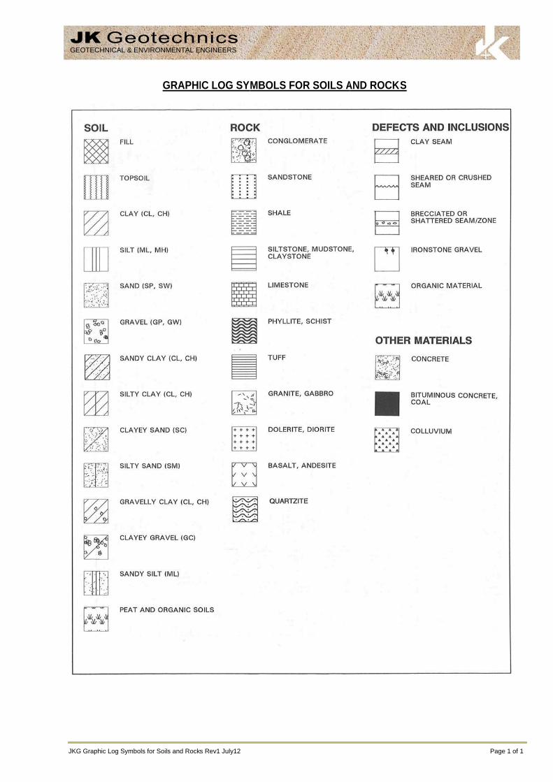
JKG Graph
GEOTEC
hic Log Symbols fo
HNICAL & ENVI
or Soils and Rock
GRAPHI
RONMENTAL E
s Rev1 July12
IC LOG SY
NGINEERS
MBOLS FOOR SOILS AAND ROCKSKS
Pag
ge 1 of 1
Note:
1 Soils possessing2 Soils with liquid
g characteristics of twolimits of the order of 3
UNIF
o groups are designat35 to 50 may be visual
FIED SOIL
ted by combinations olly classified as being
CLASSIFIC
of group symbols (eg. Gof medium plasticity.
CATION TA
GW-GC, well graded g
ABLE
gravel-sand mixture wwith clay fines).

JKG Log S
LOG
Groundw
Samples
Field Te
Moisture(Cohesiv (Cohesio
Strength(ConsistCohesiv
Density Relative(Cohesio
Hand PeReading
Remarks
GEOTEC
ymbols Rev1 Jun
G COLUMN
water Record
s
ests
e Condition ve Soils)
onless Soils)
h tency)
ve Soils
Index/ e Density onless Soils)
enetrometer gs
s
CHNICAL & ENV
e12
SYMBOL
ES U50 DB DS
ASB ASS SAL
N = 17 4, 7, 10
Nc = 5
7
3R
VNS = 25
PID = 100
MC>PL MC≈PL MC<PL
D M W
VS S F St
VSt H
( )
VL L
MD D
VD ( )
300 250
‘V’ bit
‘TC’ bit
60
VIRONMENTAL
C
4
Standing wa
Extent of bo
Groundwate
Soil sample Undisturbed Bulk disturbeSmall disturbSoil sample Soil sample Soil sample
Standard Peshow blows
Solid Cone Pfigures show ‘R’ refers to
R
Vane shear
Photoionisat
Moisture conMoisture conMoisture conDRY –MOIST –WET –
VERY SOFTSOFTFIRMSTIFFVERY STIFFHARDBracketed sy
Density IndVery LooseLooseMedium DenDenseVery DenseBracketed sy
Numbers indnoted otherwise.
Hardened st
Tungsten caPenetration rotation of au
ENGINEERS
LOG SYM
ater level. Time d
rehole collapse s
er seepage into b
taken over depth 50mm diametered sample takenbed bag sample taken over depthtaken over depthtaken over depth
enetration Test (Sper 150mm pen
Penetration Testw blows per 150mo apparent hamm
reading in kPa o
tion detector rea
ntent estimated tntent estimated tntent estimated t
– Runs freely t– Does not run– Free water vi
T – Unconfin – Unconfin – Unconfin – Unconfin
F – Unconfin -– Unconfin
ymbol indicates
ex (ID) Range (%<1515-35
nse 35-6565-85>85
ymbol indicates
dicate individual
teel ‘V’ shaped b
arbide wing bit. of auger string inugers.
MBOLS
D
delay following c
shortly after drilli
borehole or exca
h indicated, for er tube sample ta
n over depth indictaken over dept
h indicated, for ah indicated, for ah indicated, for s
SPT) performed etration. ‘R’ as n
t (SCPT) performmm penetration fmer refusal within
of Undrained She
ding in ppm (So
to be greater thato be approximatto be less than phrough fingers. freely but no freisible on soil surf
ned compressivened compressivened compressivened compressivened compressivened compressiveestimated consis
%)
estimated densit
test results in kP
bit.
n mm under stat
EFINITION
completion of dril
ng.
vation noted dur
environmental anken over depth incated. h indicated.
asbestos screeniacid sulfate soil asalinity analysis.
between depthsnoted below.
med between depfor 60 degree son the correspond
ear Strength.
il sample headsp
n plastic limit. tely equal to plas
plastic limit.
ee water visible oface.
e strength less the strength 25-50e strength 50-10e strength 100-2e strength 200-4e strength greatestency based on
SPT ‘N
ty based on ease
Pa on representa
ic load of rig app
lling may be sho
ring drilling or ex
nalysis. ndicated.
ing. analysis.
s indicated by lin
pths indicated byolid cone driven bing 150mm dept
pace test).
stic limit.
on soil surface.
han 25kPa 0kPa 00kPa 200kPa 400kPa er than 400kPa n tactile examina
N’ Value Range ( 0-4 4-10 10-30 30-50 >50
e of drilling or ot
ative undisturbed
plied by drill head
Pag
own.
xcavation.
es. Individual fig
y lines. Individuaby SPT hammer.th increment.
tion or other test
(Blows/300mm)
0 0
her tests.
d material unless
d hydraulics with
ge 1 of 2
gures
al .
ts.
)
s
hout

JKG Log Symbols Rev
ROCK M
Residual
Extremel
Distinctly
Slightly w
Fresh roc
ROCK SRock strenbedding. Abstract V
TE
Extremel
------------
Very Low
------------
Low:
------------
Medium
------------
High:
------------
Very Hig
------------
Extremel
ABBRE
ABBR
v1 June12
MATERIAL W
TERM
l Soil
ly weathered roc
y weathered rock
weathered rock
ck
STRENGTH ngth is defined bThe test proc
Volume 22, No 2,
ERM SY
ly Low:
------------
w:
------------
------------
Strength:
------------
------------
h:
------------
ly High:
----
----
----
----
-----
-----
EVIATIONS U
REVIATION
Be CS J P
Un S R IS
XWS Cr 60t
WEATHERIN
SYMBO
RS
ck XW
k DW
SW
FR
by the Point Loacedure is desc 1985.
YMBOL Is (5
EL
-----------
VL
-----------
L
-----------
M
-----------
H
-----------
VH
-----------
EH
USED IN DE
DES
Bedding Plane Clay Seam Joint Planar Undulating Smooth Rough Ironstained Extremely WeaCrushed Seam Thickness of de
LO
NG CLASSIF
OL
Soil develoevident; th
Rock is weremoulded
Rock strenironstainingweathering
Rock is slig
Rock show
d Strength Indexribed by the
50) MPa
0.03
0.1
0.3
1
3
10
Eas May A pieknife
A piewith A piescra
A pieone
A pieRing
EFECT DESC
SCRIPTION
Parting
thered Seam
efect in millimetre
OG SYMBOL
FICATION
oped on extremelyhere is a large cha
eathered to such , in water.
ngth usually chang. Porosity mayg products in pore
ghtly discoloured
ws no sign of deco
x (Is 50) and refInternational Jo
ily remoulded by
y be crumbled in t
ece of core 150me. Sharp edges o
ece of core 150m knife.
ece of core 150matched or scored w
ece of core 150mblow. Cannot be
ece of core 150mgs when struck wi
CRIPTION
es
Defec(ie re
LS continue
D
y weathered rockange in volume bu
an extent that it
nged by weathery be increased bes.
but shows little or
omposition or stain
fers to the strengournal of Rock
hand to a materia
he hand. Sandst
mm long x 50mm dof core may be fria
mm long x 50mm d
mm long x 50mm dwith knife; rock ri
mm long x 50mm de scratched with p
mm long x 50mm dith a hammer.
ct orientations melative to horizont
d
DEFINITION
k; the mass strucut the soil has not
has “soil” proper
ring. The rock y leaching, or m
r no change of str
ning.
gth of the rock sk Mechanics, M
FIELD GUIDE
al with soil propert
one is “sugary” an
dia. may be brokeable and break du
dia. can be broken
dia. core cannot bngs under hamme
dia. may be brokeen knife; rock rin
dia. is very difficul
NOT
measured relativetal for vertical ho
cture and substant been significantl
rties, ie it either d
may be highly dmay be decreased
rength from fresh
substance in theMining, Science
E
ties.
nd friable.
en by hand and eauring handling.
n by hand with dif
be broken by hander.
en with hand-held ngs under hamme
lt to break with ha
TES
e to the normal oles)
Page
nce fabric are no y transported.
disintegrates or c
discoloured, usuad due to deposit
rock.
direction normae and Geomec
asily scored with a
fficulty. Readily s
d, can be slightly
pick after more ther.
and-held hammer.
to the long core
2 of 2
longer
can be
ally by tion of
al to the chanics.
a
cored
han
.
e axis