reliazation of a physical forest demonstrator - a scaled ...541727/fulltext01.pdf · realization of...
TRANSCRIPT

Realization of a physical forest machine demonstrator
- A scaled modular approach
ATHUL VASUDEV
KAVIRESH M. BHANDARI
Master of Science Thesis
Stockholm, Sweden 2012


3
Realization of a physical forest machine demonstrator - A scaled modular approach
Athul Vasudev
Kaviresh M. Bhandari
Master of Science Thesis MMK 2012:35 MKN 063
KTH Industrial Engineering and Management
Machine Design
SE-100 44 STOCKHOLM

4

5
Examensarbete MMK 2012:35 MKN 063
Realisering av en modulär skogsmaskin
- En skalmodell
Athul Vasudev
Kaviresh M. Bhandari
Godkänt
2012-06-15
Examinator
Kjell Andersson
Handledare
Kjell Andersson
Uppdragsgivare
Skogforsk
Kontaktperson
Björn Löfgren
Sammanfattning
Trä för kommersiellt bruk avverkas med hjälp av skogsmaskiner som skördare och skotare.
Skördaren fäller, kvistar och kapar träd i längder medan skotaren transporterar detta timmer till
en uppsamlingsplats för vidare transport till sågverk och processindustri. Framtida
skogsmaskiner måste vara mycket skonsammare mot såväl maskinoperatören som mark än vad
dagens maskiner är. Detta innebär att nya maskiner och lösningar måste utvecklas och testas. En
fysisk prototyp i form av en skalmodell är en användbar ansats för att testa hur olika typer av
lösningar för hjul- och hyttupphängningar, däck, kran arkitekturer mm kan realiseras. Syftet med
detta projekt var att utveckla en sådan fysisk prototyp av en skogsmaskin i skala 1:5 vilken har
namngetts som Skogbil.
En skalningsstrategi användes för att komma fram till en specifikation av skalade dimensioner
och egenskaper för Skogbil som är jämförbara med en fullskalemodell. Modular Function
Deployment, MFD har använts för att identifiera såväl moduler som arkitektur för systemet.
Därefter har olika arkitekturer för en skogsmaskin genererats, bl.a. med pendelarm, boogiearm
och flytande framaxel. Den föreslagna skotarens arkitektur består av flytande framaxel vilket
idag inte är vanligt bland Skotare.
Skogbil kommer att drivas med 8, 50 W navmonterade borstlösa motorer med integrerad
växellåda och styras med en fjärrkontroll. Den kompletta drivlinan drivs av 24 V batterier medan
styrleden använder sig av 2 st standard R/C servon som drivs med ett 7.4 V Li-Po batteri.
Verifiering och jämförelse av dynamiskt beteendet av Skogbil med en fullskalig skotare har
utförts på såväl komponent som systemnivå.

6

7
Master of Science Thesis MMK 2012:35 MKN 063
Realization of a physical forest machine demonstrator
- A scaled modular approach
Athul Vasudev
Kaviresh M. Bhandari
Approved
2012-06-15
Examiner
Kjell Andersson
Supervisor
Kjell Andersson
Commissioner
Skogforsk
Contact person
Björn Löfgren
Abstract
Wood for commercial use is harvested from forests using forest machines like harvesters which
folds, branches and cuts trees and forwarders which transports logs to a landing area for further
transport to a processing facility. Future forest machines have to be much gentler to the machine
operators and forest soil than today's machines. Hence new machine solutions must be developed
and tested. A practical way is to develop a physical scale model which can be used as a test-bed
to incorporate different types of solutions for suspensions, cabin damping, tires and tracks, crane
and overall architecture. The aim of this project was to develop such a 1:5 scale model of a forest
machine, named as – Skogbil.
A scaling strategy was employed to arrive at important scale dimensions and specifications of
Skogbil which would be comparable to the full scale model. Modular function deployment was
implemented to identify modules and architecture of the system. Following this, various concepts
of forest machine with pendulum arms, boogie arms and live axle suspensions were generated. A
new architecture is proposed and manufactured with live axle suspension which is not common
among forwarders today.
Skogbil will be driven using 8, 50 W hub-mounted brushless motors and gearboxes which would
be controlled using a remote control. The complete driveline is powered by 24 V batteries
whereas the articulation is powered using 2 standard R/C servos with a 7.4 V Li-Po battery.
Component and system level verifications are performed to compare the dynamic behavior of
Skogbil with a full scale forwarder.

8

9
FOREWORD
Here we would like to thank all those who have contributed with their help, guidance, motivation
and assistance during the thesis work.
This Master thesis work is an outcome of the Forest Technology Academy, a co-operation
between KTH – Royal Institute of Technology and Skogforsk, Forest research institute of
Sweden and supported by many sponsor companies like Rottne, John Deere, Ponsse, Gremo,
Trelleborg and Komatsu Forest, which is greatly acknowledged.
First and foremost we would like to thank our supervisor and teacher Professor Kjell Andersson
for his continuous support, guidance and help in ordering materials and components for the
forwarder. We would also like to thank our teacher, Professor Ulf Sellgren for his motivation and
advice in developing innovative architectures of the forwarder.
Thank you Dr. Björn Löfgren, Skogforsk for supporting our decisions and Professor Jan
Wikander for your comments and suggestion during the pulse meetings. We would like to
immensely thank Thomas Östberg, Lab and workshop supervisor, for manufacturing number of
components for the forwarder. In spite of the language barrier, all our detail drawings spoke to
him and without his patience and help it wouldn’t have been possible to realize the forwarder.
Thank you Martin Nyström for arranging our technical visit to Rottne Industri AB, Växjö.
We would further like to thank Staffan Qvarnström for providing laboratory support, Björn
Möller for helping with 3D printing machine, Hampus Krantz for making many water-jet parts
for us, Mikael Hellgren for his guidance with controllers and sharing the eco-marathon tools,
Peter Georén for his help with batteries, Johannes Edrén for his motivation and guidance with
scale down vehicles, Abdurasul Pirnazarov for his help with understanding forestry tires.
Thanks to our fellow colleagues Girish Kasturi, Madura Wijekoon, Sun Xuan, Zhenduo Wang,
Qiwu Wang, and Samuel Joseph for being there with us throughout our thesis. Thanks to all our
classmates for being there with us, we will miss you all!
Last but not the least we would like to thank our Parents and Siblings for their love, continuous
motivation and moral support throughout our Master program.
Athul Vasudev
Kaviresh M. Bhandari
Stockholm, June 2012

10

11
NOMENCLATURE AND GLOSSARY
Latin symbols Description Unit
Characteristic length of the full scale (m)
Characteristic length of the scale model (m)
n RPM at the wheel (rpm)
V Velocity of the forwarder (m/s)
Radius of the tire of the scale model (m)
Greek symbols Description Unit
Scaling factor for length (-)
Scaling factor for time (-)
Scaling factor for area (-)
Scaling factor for volume (-)
Scaling factor for velocity (-)
Scaling factor for acceleration (-)
Scaling factor for density (-)
Density of steel (kg/m3)
Density of aluminum (kg/m3)
Scaling factor for mass (-)
Scaling factor for inertia (-)
Scaling factor for force (-)
Scaling factor for Torque (-)
Scaling factor for stiffness (-)
Scaling factor for damping (-)
Scaling factor for pressure (-)

12

13
TABLE OF CONTENTS
SAMMANFATTNING (SWEDISH)………………………………………………5
ABSTRACT………………………………………………………………………..7
FOREWORD……………………………………………………………………….9
NOMENCLATURE………………………………………………………………11
TABLE OF CONTENTS…………………………………………………………13
LIST OF FIGURES……………………………………………………………….17
LIST OF TABLES………………………………………………………………...19
1 INTRODUCTION…………………………………………………………...21
1.1 Background…………………………………………………………….21
1.2 Purpose and objectives…………………………………………………21
1.3 Scope…………………………………………………………………...22
1.4 Delimitations…………………………………………………………...22
1.5 Thesis overview………………………………………………………...23
2 FRAME OF REFERENCE………………………………………………….25
2.1 Market survey……………………………………………………..…....25
2.2 Requirements specification…………………………………………….27
2.3 Scaling strategy……………………………………………………...…27
2.3.1 Dimensional analysis…………………………………………...28
2.3.2 Geometric scaling………………………………………………29
2.4 Modular design…………………………………………………………30
2.5 Design methodology…………………………………………………....34

14
3 DESIGN……………………………………………………………………..35
3.1 Scaled dimensions……………………………………………………...35
3.2 Product modules………………………………………………………..35
3.3 Product architecture and interfaces…………………………………….37
3.4 Vehicle dynamics………………………………………………………37
3.5 Concept design…………………………………………………………38
3.6 Frame concepts…………………………………………………………40
3.7 Suspension concepts……………………………………………………40
3.8 Concept forwarders…………………………………………………….41
3.9 Concept selection………………………………………………………42
3.10 Detail design……………………………………………………………42
3.10.1 Design guideline……………………………………………..42
3. 10.2 Interface design……………………………………………...43
3. 10.3 Frame………………………………………………………...44
3.10.4 Suspension…………………………………………………...45
3.10.5 Cabin………………………………………………………...45
3.10.6 Articulation and steering mechanism………………………..46
3.10.7 Bunk and gate………………………………………………..48
3.10.8 Tire selection………………………………………………...48
3.10.9 Radio equipment selection ……………………….…………49
3.10.10 Motor, gearbox and controller selection………………….....49
3.10.11 Driveline layout……………………………………………...50
4 VERIFICATION…………………………………………………………….53

15
4.1 Component verification ………………………………………………..53
4.1.1 Strength verification ………………………………………...53
4.2 System verification……………………………………………………..55
4.3 Functional testing………………………………………………………56
4.4 Requirement validation………………………………………………...57
5 RESULT……………………………………………………………………..59
6 DISCUSSIONS………………………………………………………...........61
7 CONCLUSIONS AND FUTURE WORK ………………………………….63
8 REFERENCES………………………………………………………………65
APPENDIX A: MARKET SURVEY …………………………………………….67
APPENDIX B: RERQUIREMENTS SPECIFICATION …..…………………….69
APPENDIX C: CHART OF MFD… …………………………………………….71
APPENDIX D: MODULE INDICATION MATRIX…....……………………….73
APPENDIX E: FUNCTION MEANS DIAGRAM……………………………….75
APPENDIX F: SIMULINK MODEL… ……...………………………………….77
APPENDIX G: MOTOR & GEAR - SPECIFICATIONS………………………..79
APPENDIX H: REQUIREMENTS VALIDATION……………………………...81
APPENDIX I: VERIFICATION - MASS AND INERTIA…................................83
APPENDIX J: SKOGBIL PICTURES……………….…………………………...85

16

17
LIST OF FIGURES
Figure 1. SMV Rapid – a typical forest forwarder (Rottne AB, 2012). ....................................... 21
Figure 2. Rottne F18 (Rottne AB, 2012) and a Komatsu 860.4 (komatsu.se, 2012) .................... 25
Figure 3. Boogie arm suspension for forwarders, (forestmachines.ru, 2012) .............................. 26
Figure 4. The EL-Forest GT-8 forwarder bunk (el-forest.se, 2012) ............................................ 26
Figure 5. Eco Log pendulum arm suspension (eco-log.se, 2012) ............................................... 26
Figure 6. Eco Log pendulum arm suspension on 580C and 550D harvester ............................... 27
Figure 7. Valmet 860.4 (komatsu.se, 2012) ............................................................................... 28
Figure 8: Function structure heuristics - Börjesson (2012). ........................................................ 31
Figure 9. Chart of MFD (MF2011, 2011) .................................................................................. 32
Figure 10. Steps involved in MFD - Erixon (1998) .................................................................... 33
Figure 11. Design methodology - a V-Model - MF2011, KTH, (2011) ...................................... 34
Figure 12. Interface matrix between different modules .............................................................. 37
Figure 13. Power and torque requirement for Skogbil according to the Simulink - vehicle
dynamics model ........................................................................................................................ 38
Figure 14. Concept sketches for vehicle architecture ................................................................. 39
Figure 15. Different frame concepts .......................................................................................... 40
Figure 16. Concepts for forwarder suspension ........................................................................... 41
Figure 17. Concepts for Skogbil ................................................................................................ 42
Figure 18. Frame-suspension interface ...................................................................................... 43
Figure 19. Interfaces representation for articulation ................................................................... 44
Figure 20. Frame-cabin Interface ............................................................................................... 44
Figure 21. Suspension arm, motor and wheel interfaces............................................................. 44
Figure 22. Frame ....................................................................................................................... 45
Figure 23. Suspension arm ........................................................................................................ 45
Figure 24. Cabin........................................................................................................................ 45
Figure 25. Passive cabin damper (Mecmove AB, 2012). ............................................................ 46
Figure 26. Articulation .............................................................................................................. 46
Figure 27. Steering force calculation ......................................................................................... 47
Figure 28. Torque requirement at different steering angles ........................................................ 47
Figure 29. Articulation steering mechanism for Skogbil............................................................. 47
Figure 30. Implemented steering mechanism ............................................................................. 47
Figure 31. Skogbil’s bunk and gate ............................................................................................ 48
Figure 32. Futaba 4PKS transmitter with R614FS receiver (Futaba, Surface systems, 2012)...... 49
Figure 33. Skogbil's driveline layout .......................................................................................... 52
Figure 34. Frame analysis.......................................................................................................... 53
Figure 35. Suspension interface plate analysis ........................................................................... 54
Figure 36. Motor hub ................................................................................................................ 54
Figure 37. Bunk and gate .......................................................................................................... 54

18
Figure 38. Centre of gravity loaded and unloaded ...................................................................... 55
Figure 39. Steering layout of Skogbil ......................................................................................... 56
Figure 40. Grade ability test with one wheel traction with front frame ....................................... 57
Figure 41. Overall dimensions of Skogbil .................................................................................. 59

19
LIST OF TABLES
Table 1. Dimensionless Pi groups to verify dynamic similitude ................................................. 29
Table 2. Scaled dimension for Skogbil from the scaling strategy ................................................ 35
Table 3. List of modules and associated forwarder components ................................................. 36
Table 4. Vehicle parameters based on vehicle dynamics model ................................................. 38
Table 5. Specifications of the passive cabin damper (Mecmove AB, 2012). .............................. 46
Table 6. Load - deflection relationship of Trelleborg 710/45-26.5 T428 tire .............................. 48
Table 7. Specifications of tire selected for Skogbil ..................................................................... 49
Table 8. CG comparison ............................................................................................................ 55
Table 9. Bill of material for Skogbil .......................................................................................... 59

20

21
1 INTRODUCTION
In this chapter brief introduction, problem description, purpose and delimitations are presented.
The thesis overview is discussed in brief.
1.1 Background
The predominant forest harvesting method is the Cut-To-Length (CTL) method, based on a two-
machine solution – a harvester and a forwarder. A harvester is a machine which used for CTL
logging of the forest trees. In short it folds, branches and cuts trees. A forwarder is used to carry
the felled logs from the forest to a landing area. Simply stated, the forwarder transports logs to a
loading area for further transport to a processing facility. A typical forwarder in a forest
environment looks as shown in Figure 1.
Figure 1. SMV Rapid – a typical forest forwarder (Rottne AB, 2012).
In contrast a harwarder is a machine which performs both the functions of the harvester and the
forwarder. The present-state-of art in the forwarders have not seen major architectural changes in
their design. Also the new machines require being much gentler to the ground and the operator.
1.2 Purpose and objectives
Soil damage and operator comfort are currently the main issues in the existing forest machines.
The soil damage and the corresponding rut formation are mainly due to the high ground pressure
exerted by the forest machine. Also, with higher standard requirements imposed on improving
operator comfort has led to a challenge to develop and test new damping solutions like active,
semi-active and testing of different passive dampers. Further, historically the architecture of the
forest machines has been similar for all the manufacturers. Hence the research for finding new
solutions for better architecture than prevailing ones is on the rise.
The new machine solutions have to be much gentler to the machine operators than today's
machines. It is particularly important to develop new machine concepts that are gentle to the
terrain and thus reduce damages on the soil and the remaining trees. To reduce soil damage,

22
different types of tracks, tires, rear suspension, frame, damping equipment, etc. can be tested on
a machine. However, full scale testing on an actual forest machine is complicated and expensive.
It is due the fact that full scale testing involves huge costs, time and the inherent risk of making
mistakes and arriving at non-useful or misleading results.
A practical and relatively easy and less costly method to evaluate different design principles is
the use of a physical scale down prototype. It is important that the physical scale model is able to
adapt for future innovations which can be tested and analyzed on it. Hence a need is identified to
develop, and physically realize, a scale-down modular forest machine demonstrator, a forwarder
in principle. The forwarder should be able to adapt different new solutions and provide results
comparable to real forest forwarder. This scale-down model thus provides to be a platform for
development and empirical testing of new solutions for the forest machines. It can also provide
to be a test bench to try different future autonomous/semi-autonomous machine solutions by
using forest machine simulator or remote controls.
This master thesis was intended to create a scaled model of a forwarder which has been named as
“Skogbil”, with co-operation and assistance from expertise at the KTH - Royal Institute of
Technology, Skogforsk – Forest research institute of Sweden, and the leading forest machine
manufacturers.
1.3 Scope
The overall aim of the project is to create a modular physical 1:5 scale model of a forwarder. The
scale model shall be easy to adapt to different types of traction and ground contact devices so
that different alternative sub-solutions can be tested and presented. The main requirements of the
vehicle can be summarized as below.
Modular design to adapt different subsystem solutions.
Comparable to real full scale machine, e.g. in case of frequencies of the system.
Able to perform ground pressure test and vibration test in the cabin.
Provide provision for future innovation.
Remote controlled.
1.4 Delimitations
The project will focus mainly on developing a forest machine demonstrator which is modular
and can be upgraded in the future. The main focus of the project will be in modular design of the
forwarder so that future improvements can be implemented. Following are some of the
delimitations for the project.
Sensors, filters and other testing equipment’s which need to be implemented in the
vehicle will be analyzed, but the selection of parts and their mechatronic controlling is
not considered for this project. However, due considerations and provision will be made
to mount the testing equipments and sensors on the Skogbil.
A detailed model of the crane for the vehicle will not be developed, but weight of the
crane will be added on the vehicle to match the frequency and performance compared to a
full scale machine.

23
The machine will be developed to appear like a real forwarder but detail design of interior
and aesthetic parts are not considered and are out of the scope.
Interfaces of different modules will be developed to adapt different solutions. Detail
design of one configuration of the forwarder will be manufactured. However, if time
permits further configuration would be investigated, reported and at last manufactured.
1.5 Thesis overview
The background and scope of the thesis is described in the current chapter. Chapter 2 focuses
mainly on literature review, formulation of the design methodology and study about scaling
strategies.
Chapter 3 gives insight to the concept generation and detail design of the all the components.
This chapter also discusses about the result from different scaling strategies, vehicle dynamics
calculation and various modules generated.
Chapter 4 focuses mainly on the verification and validation of different components and
subsystems which have been designed
Chapter 5 presents the overall result of the thesis with the bill of materials. Chapter 6 presents
brief discussions; Chapter 7 enumerates the conclusion and future work. Chapter 8 lists all the
references followed by the appendices.

24

25
2 FRAME OF REFERENCE
The market study performed is described briefly with the major components of the forwarder
followed by the requirement specifications for Skogbil. It also consists of the scaling strategy and
modularization method. A V-model used for the design and development of Skogbil is presented.
2.1 Market survey
The configurations and technical details of forest machines like harvesters, forwarders,
harwarders and concept machines were studied and their specifications were noted. It was
necessary to look at different configurations of forest machines to know the state-of-art of the
present forest machines. A visit to Rottne Industri AB, gave insight to the different components
of the forwarder and harvester. Figure 2 shows a Rottne F18 and a Komatsu 860.4 forwarder.
Figure 2. Rottne F18 (Rottne AB, 2012) and a Komatsu 860.4 (komatsu.se, 2012)
The forwarder consists of various major systems like – driveline, suspension, articulation, axle
steering, crane, cabin & seating arrangement, frame and bunk. The driveline of the forwarder
works on hydrostatic transmission. A diesel engine is coupled with hydraulic motors which
drives the hydraulic gearbox. The hydraulic gearbox then transfers the required torque to the
individual boogie/pendulum arms via a differential.
Forest machines usually have boogie arm, pendulum arm or live axle suspensions. Figure 3
shows a boogie arm from HSM GmbH & Co. KG.

26
Figure 3. Boogie arm suspension for forwarders, (forestmachines.ru, 2012)
The EL-Forest GT-8, see Figure 4, is a remote controlled forwarder bunk with hybrid electric
driveline and live axle suspension. The Skogbil’s suspension was inspired from GT-8’s
suspension system.
Figure 4. The EL-Forest GT-8 forwarder bunk (el-forest.se, 2012)
A pendulum arm suspension is common in harvester machines. Figure 5 shows an Eco Log
harvester climbing over a gradient surface and the behavior of pendulum arm suspension. The
pendulum arm suspension provides the harvester with a better terrain adaptability and stability,
better visibility and comfort to the operator and ease of maintenance.
Figure 5. Eco Log pendulum arm suspension (eco-log.se, 2012)

27
The Figure 6(a), shows Eco Log 580C harvester with pendulum arm suspension on front frame
and boogie arm suspension on the rear frame. Whereas the Figure 6(b) shows a 550D harvester
having each wheel suspended using a pendulum arm. Appendix A provides an overview of a few
forest machines studied.
6(a)
6(b)
Figure 6. Eco Log pendulum arm suspension on 580C and 550D harvester
2.2 Requirements specification
Based on the market study and the purpose of the thesis, a list of requirements were formulated.
Detailed requirements specifications are presented in Appendix B. The major requirements were
to have a modular architecture of Skogbil which facilitates future innovations. Innovations like,
for example, an articulated forwarder, on which different types of suspensions like boogie arm,
pendulum arm and live axle suspension could be assembled and tested for performance, ground
pressure, vibrations, etc.
Further, innovations like, a forwarder bunk which operates as a shuttle to increase the harvesting-
forwarding capacity of forest machines. This means using a forwarder bunk as a separate wagon
which is controlled remotely and shuttles between the forests-the loading point to an unloading
or collection point. Whereas a crane, which can again be operated remotely as an independent
wagon, harvesting and loading the CTL wood onto the shuttle wagon. A combination of such
forwarder bunk wagons would keep the harvesting crane in continuous operation and increase
the capacity and thus the usage of the machines.
2.3 Scaling strategy
Skogbil is developed to reproduce the dynamic behavior of a full size forwarder. Skogbil will act
as a test bench to study and evaluate the effects of different types of suspensions, frame,
driveline, damping equipment and design principles. The study of different sub-systems on the

28
full scale forwarder is rather difficult, expensive and time consuming due to the large size,
weight and cost. The major advantages of scale model investigations are:
Design for various solutions can be produced quickly due to inherent simplicity,
Manufacturing and prototyping of sub-solutions is less expensive,
Desirable vehicle parameters can be changed easily for parametric studies,
Data collection from onboard sensors can be analyzed easily,
Handling, maintenance and control are easy and safe.
However, the results from the scale model tests may not simulate the complete physical and
dynamic behavior of the full scale forwarder, due to the inherent simplicity of the scale model.
Further, the fatigue behavior of the full scale forwarder may not be similar to the scale model.
Jaschinski et. al. (1999) refers to scaling approaches, like dimensional analysis, inspectional
analysis and geometric scaling. Dimensional analysis is used to derive dimensionless groups
from which the scaling factors could be estimated. In inspectional analysis, equations of motions
are derived then the scaling factors are derived to maintain the similarity between the full scale
and the scaled down model. Further, in geometric scaling the dimensions depend on scaling
factor.
To arrive at practical dimensions and specifications of the scale down forwarder the scaling
approaches mentioned above were implemented. Based on results from the different scaling
approaches and the availability of standard off-the-shelf components on the market the practical
specifications were arrived. The Valmet 860, Figure 7, was considered as a base reference
forwarder to arrive at the scale dimensions and specification.
Figure 7. Valmet 860.4 (komatsu.se, 2012)
The parameter ‘A’, machine width, depends upon the width of the tire chosen. The tire with
dimensions 710/45x26.5 was chosen for Valmet 860.4.
2.3.1 Dimensional analysis
As referred by Jaschinski et. al. (1999) dimensional analysis is a viable method to quantify the
agreement between the scale model and full size vehicle. Brennan (1999) has presented the proof
of Buckingham Pi Theorem of Dimensional Similitude with a method explaining the verification
of scale model using dynamic similitude. Based on the literature survey several dimensionless
groups were created to verify the dynamic similitude of Skogbil and a full-scale forwarder. These
dimensionless groups are presented in Table 1.

29
Table 1. Dimensionless Pi groups to verify dynamic similitude
Sr. No. Pi group Nomenclature
1 A/L A – Distance of CG from front axle
B – Distance of CG from Rear Axle
L – Distance between Front and Rear axle
Izz – Moment of inertia in lateral direction
T – Torque
M – Mass
U – Longitudinal Velocity
2 B/L
3 Izz/M(L^2)
4 T/M(U^2)
2.3.2 Geometric scaling
The dimensions of Valmet 860 are scaled to1/5. All the parameters are defined in nomenclature.
The length scaling factor is defined as:
The results from the dynamics studies are usually in terms of time histories or frequencies.
Hence its will be convenient to if the scale model represents the same frequency components as
the full size vehicle. Hence the time scaling factor is considered to be unity.
The scaling factor for area is defined as:
The scaling factor for volume is defined as:
The scaling factor for velocity is defined as:
The scaling factor for acceleration is defined as:
To obtain the similar dynamic behavior of the scale model of the forwarder as the full scale
model the density scaling factor of the scale model was envisioned to be 1. But due to practical
consideration, like availability of standard cross-sections of material to construct the frame and
the forwarder components, aluminum was chosen as the main building material. The density of
aluminum being 2600 kg/m3, whereas the density of the frame and other components for base
reference forwarder – Valmet 860 was considered to be 7800kg/m3, as the frame for Valmet 860
is made of steel. Thus the scaling factor for density is defined as:

30
The scaling factor for mass is defined as:
The scaling factor for inertia is defined as:
The scaling factor for force is defined as:
The scaling factor for torque is defined as:
The scaling factor for stiffness is defined as:
The scaling factor for damping is defined as:
The scaling factor for pressure is defined as:
2.4 Modular design
There are mainly two different types of product architecture – integral and modular. Integral
architecture have fixed or multiple/cross interfaces between the components or subsystems, in
short formulating different configurations of single system will become extremely difficult
.While in a modular architecture the components are clustered into groups based on their
functionality. Each clustered group has interfaces with other group/modules. This will help in
formulating different configurations by replacing modules. As one of the requirements for the
vehicle is to adapt different solutions of subsystems/components for testing, an extensive study
on modular architecture was performed. An overview of the modular design and different
methodology used in modular design was studied from the course material of MF2011course
(Systems engineering, 2011) at KTH. A methodology needs to be selected in order to move
further to design modular system and interfaces. Different methodologies were studied and
analyzed from Erixon (1998), Stake (2000) and by Blackenfelt (2001). The three methodologies
identified for modularization were:
1. Function structure heuristic method - Börjesson (2010).
Function heuristic method separates modules from single product architecture by finding the
dominant, branching flows or the conversion-transmission function pairs. The functions are
categorized and grouped based on the flow between different components, see Figure 8.

31
Figure 8: Function structure heuristics - Börjesson (2012).
2. Modular Function Deployment (MFD)
MFD is a well-established methodology for strategic modularization. Modular function
deployment, Erixon (1998) has following steps for establishing and developing module based
design.
1. Clarify product specifications
2. Analyze functions and select technical solutions
3. Identify product modules
4. Evaluate Concepts
5. Improve each module
A ‘Chart of modular MFD’ as shown in Figure 9, Erixon (1998) is used for integration of
different aspects of modular design i.e. from customer requirements to module indication matrix
(MIM). Customer Requirement Function Matrix (CFM), Function Means Matrix (FMM) and
Design Structure Matrix (DSM) were also used along with MIM to plot a better idea about the
modules to be developed. Functional decomposition and function means tree were studied with
aid of the existing function means tree developed for a forwarder in systems engineering course
(MF2011, KTH).

32
Figure 9. Chart of MFD (MF2011, 2011)
Tools to be used to complete these steps are mentioned in Figure 10. Following are the important
tools used.
Quality Function Deployment (QFD): QFD is a tool used to transform customer or end
user needs to design requirements and specifications. It helps to identify the product
properties which fulfill the customer requirement while it also considers the competitors’
products.
Function Means Diagram: Based on the design requirements, main functions of the
system are defined and means or solution to satisfy these functions are analyzed and
plotted. This process continues until lowest levels of solutions are reached. Further a
detailed function means diagram generated for this thesis is shown in Appendix E.
Module Indication Matrix (MIM): Module indication matrix is used to identify the
purpose of each components and group together to form a potential module. Main module
drivers are mentioned in the step 3 of the 5 different steps of Modular Function
Deployment (MFD) in Figure 10. These drivers determine the scope and functionality of
each component at different stages of product development.
Module Evaluation Matrix: Following the identification of modules the next step is to
define the product architecture. This is performed by using module evaluation matrix
which helps in plotting the interfaces between each module and hence it helps to define
the product architecture.
33
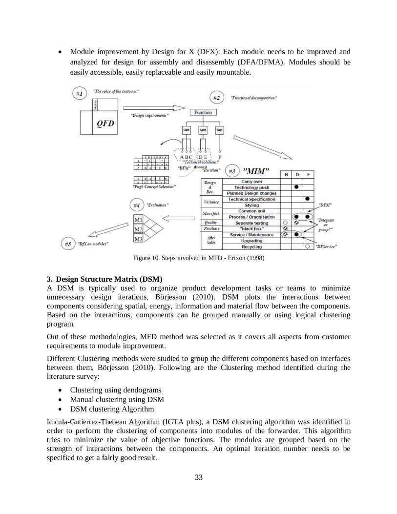
Module improvement by Design for X (DFX): Each module needs to be improved and
analyzed for design for assembly and disassembly (DFA/DFMA). Modules should be
easily accessible, easily replaceable and easily mountable.
Figure 10. Steps involved in MFD - Erixon (1998)
3. Design Structure Matrix (DSM)
A DSM is typically used to organize product development tasks or teams to minimize
unnecessary design iterations, Börjesson (2010). DSM plots the interactions between
components considering spatial, energy, information and material flow between the components.
Based on the interactions, components can be grouped manually or using logical clustering
program.
Out of these methodologies, MFD method was selected as it covers all aspects from customer
requirements to module improvement.
Different Clustering methods were studied to group the different components based on interfaces
between them, Börjesson (2010). Following are the Clustering method identified during the
literature survey:
Clustering using dendograms
Manual clustering using DSM
DSM clustering Algorithm
Idicula-Gutierrez-Thebeau Algorithm (IGTA plus), a DSM clustering algorithm was identified in
order to perform the clustering of components into modules of the forwarder. This algorithm
tries to minimize the value of objective functions. The modules are grouped based on the
strength of interactions between the components. An optimal iteration number needs to be
specified to get a fairly good result.

34
2.5 Design methodology
There are different methodologies for system level product design. Many methods have been
identified and analyzed from course (MF2011, KTH). A V-model as shown in Figure 11, below
was identified to be followed to develop Skogbil.
Figure 11. Design methodology - a V-Model - MF2011, KTH, (2011)
One of the requirements of the project is to make the vehicle modular. So in order to design a
modular product, a Modular Function Deployment (MFD) is implemented from the step of
‘Identification of customer needs’ to ‘Sub-system definition’.
MF
D

35
3 DESIGN
This chapter is the heart of the thesis and provides the details about the dimensions of Skogbil,
its different modules, architecture and interfaces. It also consists of the calculations from vehicle
dynamics, different concepts, detail design of individual components and selection of off-the-
shelf components.
3.1 Scaled dimensions
Considering the Valmet 860.4 dimensions and specifications, as presented in Appendix A,
applying the scaling strategy, scaled dimensions and specifications for Skogbil can be arrived at.
Table 2 presents the scaled dimensions of Skogbil.
Table 2. Scaled dimension for Skogbil from the scaling strategy
1/5th scale of Valmet 860.4 – Skogbil
Parameter Value
Frame Length (mm) Front 834
Rear 1080
Loader height (mm) 762
Width (mm) 598
Ground Clearance 136
Loading bay area (m2) 0.13 – 0.19
Self-weight 8WD (kg) 43
Load Capacity (kg) 38
Max. Tractive effort (kN) 93
Off-road speed (km/h) 1.4
Tires size 140 mm wide
– 270 mm dia.
However, due to the density scaling as explained in section 2.3.2, the force required is too less
and is unrealistic. Hence the scaling for force is not followed for the dimensioning for tractive
force, i.e. the motors and gearboxes which provide the necessary torque and tractive force to
Skogbil. Further, in section 3.10.10, motor and gearbox selection are explained.
3.2 Product modules
As discussed in section 2.4, different steps involved in identifying and defining modules have
been executed with a predefined modified chart for MFD and IGTA clustering Algorithm .The
Chart of MFD, Module Indication Matrix (MIM) and the Function means diagram is been
appended in Appendix C, D and E respectively. These three processes help in accomplishing first
3 stages in Modular Function Deployment. Table 3 suggests the potential modules to be
developed for the project.

36
Table 3. List of modules and associated forwarder components
Forwarder components Module
number Module
DC motor
1 Motor Motor mount
Hub reduction gear
Shaft rim connection 2 Traction
Rim and tire
Traction suspension 3 Suspension
Traction frame attachment
4 Chassis
Frame
Front frame articulation joint
Rear frame articulation joint
Damper frame joint
Test system enclosure
Gate to frame attachment
Bunk to frame attachment
Crane to frame mount
Electric actuator 5 Articulation
Universal joint
RC transmitter
6 RC
RC receiver
Signal cables
Microcontroller and motor
driver
Cabin cage
7 Cabin
Cabin cover plates
Damper - cab joint
Cabin door
Cabin ladder
Sensors
8 Test SD card storage
Filters
Gate
9 Bunk & gate Bunks
Crane
Electric cables 10 Power supply
Electric battery
Vibration damper 11 Cabin damper

37
3.3 Product architecture and interfaces
Identification of modules follows with identifying the interfaces between the modules and hence
defining the product architecture. Figure 12 represents the interface matrix between different
modules. Symbols g, e and s represent geometric, energy flow and signal flow between modules.
From this graph it can be clearly observed that most of the components have interface with the
chassis or the frame. So the product architecture can be defined as a bus modular architecture as
most of the components are mounted on a common platform. This completes the 4th stage in the
Modular Function Deployment process i.e. evaluation of concepts.
Figure 12. Interface matrix between different modules
3.4 Vehicle dynamics
In order calculate the power requirement for driving; a vehicle dynamics model was created in
Simulink (The Mathworks Inc, 2012). The Simulink model is attached in the Appendix F. The
model is based on the equation of motion for ground vehicles.
( )
Where, F x=Total Tractive Force.
Torque, Tx = F x *
Power, P = Tx* /
Other vehicle parameters are explained along with their values, see Table 4.

38
Table 4. Vehicle parameters based on vehicle dynamics model
Vehicle parameter Parameter notation Value
Vehicle mass including load
Equivalent mass of rotating parts
Frontal area
Aerodynamic drag coefficient
Rolling resistance coefficient in hard terrain,0.094 in forest
Inclination
Tire radius
Vehicle velocity Vehicle acceleration
The parameters were used in the Simulink model and power and torque characteristics of Skogbil
are calculated. The power characteristics for driving in a forest are calculated rather than
calculating for hard terrain drive. The acceleration was calculated by assuming the vehicle
reaches in maximum speed in 10 seconds. Figure 13(a) and Figure 13(b) shows the power and
torque requirement in the Skogbil respectively. As it can be observed that the vehicle is heavy
and speed requirement is low, the torque required on the wheels become substantially high, when
it needs to climb up a grade of 30°. It can be also concluded that substantial contribution to
traction comes from the power consumption in forest is due to high grades and high rolling
resistance rather than fast acceleration. Torque and power requirement of Skogbil doesn’t varies
much at both stages of acceleration and cruising.
13(a) Power requirements
13(b) Torque requirements
Figure 13. Power and torque requirement for Skogbil according to the Simulink - vehicle dynamics model
3.5 Concept design
To be able to foresee innovations discussed in section 2.2, it’s important to test different sub-
solutions and thus a scale model prototype is built as it offers many advantages. Figure 14
presents sketches to demonstrate the vehicle architecture to implement such concepts.
The sketches show concepts with pendulum and boogie arm suspension, with and without tracks.
A single remote controlled forwarder indicates an articulated frame joint steering. Whereas, the
sketches with two remote controls show cabin and crane on one single frame and forwarder bunk

39
on another separate frame which can haul as a shuttle vehicle as explained in Section 2.2.
Further, such modular architectures facilitate new concepts where pendulum or boogie arm
suspensions can be replaced with a live axle suspension and axle steering, similar to Eco Log
GT-8 (Eco Log AB, 2012) vehicle.
Figure 14. Concept sketches for vehicle architecture
The eight wheel drive (8WD), concepts have the front and rear frame joined together with the
articulation steering. Whereas the concepts with four wheels drive on each of the front and rear
frame (4 – 4WD) have separate frames without articulation steering joint. These frames cane be
remote controlled separately. Thus the cabin and crane act as one wagon and forwarder bunk acts
as another wagon.
Also, several forwarder bunk wagons can form a platoon, similar to Volvo Trucks - SARTRE
vehicle platooning project (Volvo Trucks Global, 2012), and be driven behind one another to
follow the operator driven front wagon consisting of cabin and frame.
These Initial sketches were made before proceeding further on development of concepts for
different modules/subsystems of the forwarder. This step helped to develop interfaces between
the modules, especially the interface between frame and suspension modules.

40
3.6 Frame concepts
Figure 15. Different frame concepts
Major frame concepts analyzed were the truck/open frame, box frame and single frame units, see
Figure 15. In the box frame concept, the entire frame is made out of single size square channel
while in the single frame concept the whole frame is made out of one strip of a bigger
rectangular channel into which all units will be directly mounted.
3.7 Suspension concepts
Different suspension units were developed as shown in Figure 16. Boogie arm and pendulum
arms suspensions are used in commercial forest machine while the live axles are mostly found in
off-road trucks. The Figure 16(a) shows two different types of boogie arm suspensions, one
straight arm and another with a small angle between the two arms on a boogie. It can be noted
that the boogie arm with straight configuration restricts the vertical displacement of the tire
module as the compared with the configuration with an angle between two boogie arms. Thus the
later provides better suspension while rolling over big obstacles.
16(a) – Boogie arm suspension

41
16(b) – Pendulum arm suspension
16(c) – Live axle suspension (SD2222, KTH, 2011)
Figure 16. Concepts for forwarder suspension
The Figure 16(b) shows a pendulum arm suspension. The bearing provides the necessary
rotational motion for the suspension and thus the vertical displacement of the tire module.
However a spring or linear damper is required between the pendulum arm and the vehicle chassis
to damp the vibrations induced during the vehicle operation. The concept of live axle suspension
is similar to the EL-Forest GT-8 (el-forest.se, 2012) machine. Figure 16(c) shows a live axle
concept where the tire modules are supported on a common axle beam and the beam is
suspended to the vehicle body with compression springs and struts. All the three suspension
concepts have an electric traction units comprising of motors with gearboxes mounted on motor
shaft and are not similar to, for example, Figure 3, where a geared reduction takes place
throughout the boogie arm.
3.8 Concept forwarders
The final configurations of the concepts were modeled based on the sketches, frame, suspension
units, innovation level – new architecture and modularization. The components like cabin, bunk,
gate and the articulation were conceptually made out of sheet metal components. The Figure 17
shows three final concepts for Skogbil.
The details of the concepts are:
1. Concept 1 : Box frame and bogie arms
2. Concept 2 : Single frame and pendulum arms
3. Concept 3 : Truck/open frame and live axles

42
Figure 17. Concepts for Skogbil
3.9 Concept selection
One of the delimitations the project was to focus mainly to manufacture 1 configuration of the
forwarder. So a concept was selected to proceed further with detail design. Concept 3, truck/open
frame with live axles was selected as the final configuration to be detailed due to following
reasons:
1. Easy to try with individual steering on front and rear frame
2. Possibility to remove articulation and control individual frames
3. Analyze a new architecture on forwarder
4. Easiness in manufacturing
As this is a new architecture, it will be difficult to compare it with the full scale forwarder model.
3.10 Detail design
The following sub-sections describe the detail design of the selected concepts which were then
manufactured.

43
3.10.1 Design guideline
A general design guideline was formulated in order to make the design simple and easy to
manufacture. These guidelines helped us in detail design and manufacturing adhering to a tight
time schedule. The guideline is summarized below:
Make the components from standard channels/profiles available in the market.
Design based on utilizing in-house manufacturing facilities in KTH machine design
department.
Avoid designs that need complex manufacturing techniques like casting, forging etc.
Try to utilize readily available products in market rather than making it.
Identify Swedish suppliers for the components in order to have a shorter lead time in
delivery.
Avoid permanent joints like welding, gluing etc. at the interfaces.
Standardize the components like use single size of bolts throughout the system i.e. utilize
minimum inventory.
Design the interfaces for assembly and disassembly (DFA) i.e. use minimum tools; avoid
special tools, easy accessibility and visibility.
3.10.2 Interface design
Interface definition is an important task to be performed before detailing the modules. The
critical interfaces that are identified are the frame-suspension, frame-articulation, frame-cabin
and suspension-traction interface. Frame-suspension interfaces as shown in Figure 18 was
decided to be a 5 mm thick sheet metal plate which transfer the load to the frame from
suspension and vice versa.
Figure 18. Frame-suspension interface
The frame articulation interface is made of U channels which is press fitted and fastened to the
frame as shown in Figure 19. The yaw movement at the articulation is made possible by using
two aluminum blocks with deep grove ball bearing and shaft mounted on to it.

44
Figure 19. Interfaces representation for articulation
Figure 20 shows the frame-cabin interface. Frame-cabin interface is basically a mounting plate
with rubber bushing which can act as a passive suspension. The advantage of this mounting is
that the cabin damper as well as cabin can be replaced individually.
Figure 20. Frame-cabin Interface
Figure 21. Suspension arm, motor and wheel interfaces
Figure 21 shows the interface between the traction unit, suspension arm and the wheels. The
traction from the motor is transferred to the wheels using a hub made out of steel.
3.10.3 Frame
The Frame, see Figure 22, is designed using standard aluminum U-channels as main frame and
square channel members as cross members. The length and width of the frame is based on the
scaled dimensions achieved from the scaling strategy.

45
Figure 22. Frame
3.10.4 Suspension
The suspension arm is designed using standard rectangular and circular channels cut and welded
in required length. The arm is attached to the frame interface plate with the help of bolts and
springs, see Figure 23.
Figure 23. Suspension arm
The spring is an optional component to evaluate the possibility of adding suspension in the
forwarder.
3.10.5 Cabin
Figure 24. Cabin
The cabin, see Figure 24, is made out of aluminum sheet metal with scaled dimensions from the
real forwarder. The cabin is attached to the frame with the help of rubber bushings. The rubber

46
bushing is called as Flexibloc - which is a fully bonded elastomer between two concentric steel
tubes as shown in the illustrative Figure 25.
Figure 25. Passive cabin damper (Mecmove AB, 2012).
The technical details and dimensions of the bushings are presented in Table 5.
Table 5. Specifications of the passive cabin damper (Mecmove AB, 2012).
d
(mm)
D
(mm)
L
(mm)
l
(mm)
Radial Torsion Axial Conical
Static
load
(N)
Deflection
(mm)
Max.
angle
(°)
Static
load
(N)
Deflection
(mm)
Max.
angle
(°)
12 32 40 24 1900 0.55 20 300 1 2
3.10.6 Articulation and steering mechanism
Figure 26. Articulation
The articulation joint is made out of machined U-channels, see Figure 26. The yaw motion at the
joints is achieved by adding blocks with a deep ball bearing. The yaw motion can be removed
from the system if required as the articulation joint and yaw blocks have same interface. The rear
and front frame is connected using clevis pin with support of small ball bearings.
The torque requirement for steering the vehicle is calculated by using Figure 27. The Force
required in the articulation joint is hence calculated by considering equilibrium of forces and
moments in the system. Torque is calculated based on the force and assumed length of the tie
rod. This calculation is performed to identify torque requirement in the servo. Figure 28,
represents the torque requirements at different steering angle. The max torque identified for a
single servo was 4.3 Nm. Further verification is performed by applying torque into a dynamic
model of the forwarder in Autodesk Inventor (Autodesk, 2012).

47
Figure 27. Steering force calculation
Figure 28. Torque requirement at different steering angles
Due to unavailability of high torque servos within a short delivery time, two Futaba servos
(Futaba, digital servo, 2012) of 3 Nm, was purchased and used in the model. The simplified
layout of the steering system in the forwarder is shown in Figure 29. The steering mechanism is
simulated with the help of Adams model (MSC Software, 2012) in order to identify the optimal
positions of the servos and tie rods. The length of tie rod along with distance between joints
plays an important role in determining the steering angle.
Figure 29. Articulation steering mechanism for Skogbil
Figure 30. Implemented steering mechanism

48
Based on results from the Adams simulations the optimal positions were identified and
implemented in forwarder model, see Figure 30. A maximum steering angle of ±20° was
achieved with current steering linkages.
3.10.7 Bunk and gate
As shown in Figure 31 the bunk and gate module is made out of 10 mm thick aluminum plates.
In the bunk area two, 10 mm thick plates are attached together for a better strength. The whole
module is attached to the rear frame using an interface plate.
Figure 31. Skogbil’s bunk and gate
3.10.8 Tire selection
Table 2 shows the required tire dimensions for Skogbil. A thorough market search was done to
find a tire of required dimensions and properties. However, a 140 mm wide tire with a diameter
of 270 mm was not available off-the shelf. Moreover, the available tires which closely match the
required tire dimensions have to be tested for vertical stiffness and vertical damping. So that
these values can be used to make a dynamic Adams simulations model (MSC Software, 2012).
The properties like the vertical stiffness of 710/45-26.5 T428 163A8 Trelleborg tire (Trelleborg
AB, 2012) are tabulated in the Table 6.
Table 6. Load - deflection relationship of Trelleborg 710/45-26.5 T428 tire
Pressure (bar) 4 5 6
Deflection (mm) @ road conditions, load = 4875 kg 44.55 40.32 36.87
Stiffness (N/mm) @ road conditions, load = 4875 kg 1073.48 1186.10 1297.09
Deflection (mm) @ forest conditions, load = 6000 kg 49.85 44.92 40.90
Stiffness (N/mm) @ forest conditions, load = 6000 kg 1180.74 1310.32 1439.12
The tires selected for Skogbil, is presented in Table 7. However, due to the lack of testing facility
the stiffness and damping could not be evaluated. The detail information about the different
parameters mentioned in Table 7 can be found in the Trelleborg product catalog - Tires for light
services (Trelleborg AB, 2012).

49
Table 7. Specifications of tire selected for Skogbil
Name Trelleborg tires 4” family, farming range
Picture
Size 4.10 – 4
PR/LI 4
Diameter (mm) 276
Width (mm) 104
Rim size 2.10 x 4
3.10.9 Radio equipment selection
A standard Futaba 4PK-2.4 GHz, FASST R/C radio was purchased off-the-shelf. This radio
includes a R614FS receiver. The radio has 4 channels and outputs a PWM signal on each of the
channels’ signal terminal. Figure 32 shows an image of the purchased radio transmitter and
receiver.
Figure 32. Futaba 4PKS transmitter with R614FS receiver (Futaba, Surface systems, 2012)
The receiver works fine with a 5 Ah, 7.4 V, 30 C, Li-Po (Lithium-Polymer) rechargeable battery.
However, the receiver can handle voltages in the range of 3.5 – 8.4 V. This battery can power all
the channels with 7.4 V and can also power the steering servo through the steering channel.
3.10.10 Motor, gearbox and controller selection
Brushed and brushless motors were considered for selection. Initially brushed motors were
considered to be used due to their inherent ease of control, but however due to large dimensions
in length they were rejected. Figure 13 shows that the overall power should be over 250 W. Also,
as the maximum continuous speed of Skogbil is about 1.4 km/h, hence a 50 W motor for each tire
with a gear reduction ratio of 216 was chosen.
It is always advisable to have motors with more power delivering capacity than required due to
the motor efficiency and danger of overheating at peak power requirements. Thus total power
available for Skogbil is 400 W, as Skogbil has an 8 wheel configuration. The speed requirement
on each wheel to achieve a speed of 1.4 km/h, turns out to be 28 rpm, according to equation
mentioned below.

50
The specification of the EC 45 Flat, 50 W brushless motor and GP 42 planetary gear head with a
reduction ratio of 216:1, from Maxon motor (Maxon motor ag, Product, 2012) is presented in
Appendix G.
ESCON 50/5 (Maxon motor ag, Products, 2012), a 4-quadrant PWM servo controller was chosen
for the brushless EC motors. The controller can work with brushed as well as brushless motors. It
can be configured on a computer via USB port connection and ESCON Studio software, supplied
by the manufacturer. The controller supports four digital inputs and provides 2 digital outputs. It
also supports two analog inputs and provides two analog outputs. The controller also has two
inbuilt potentiometers to provide any appropriate pre-set value input to the motor. The controller
gain can be set and fine-tuned while the configuration of the controller using ESCON Studio
software.
The controller provides three choices for the controlling the motor – speed control (closed loop),
speed control (open loop), and current control. An open loop speed controller was used to control
the motors. The PWM (Pulse Width Modulation) signal from the signal terminal of the R/C
receiver is sent to one of the digital input port of the ESCON controller which controls the speed
of the motor.
However, development of an R/C PWM interpreter circuit which can receive the signals from the
receiver and split it into eight outputs with appropriate PWM duty cycle has to be developed, for
future studies as explained in chapter 2, by Wolm (2009). Further, the interpreter circuit should
also calculate the slip at each wheel using the encoders or hall sensors available with the
brushless motors to provide appropriate torque to each which to avoid individual wheel slip.
Development of such an interpreter circuit is limited from the current thesis work.
3.10.11 Driveline layout
Skogbil has a complete electric driveline. All the eight motors are powered from two 12 V, 7.2
Ah lead-acid batteries, connected in series. The total driving time is assumed to be around 30
minutes. However, additional capacity or usage of advanced batteries would help in increasing
the driving time. The positive and the negative terminals across the series connection of the
batteries are divided into eight outputs each. Each of the ESCON 50/5 controllers are powered
from these split connections. The Figure 33 shows the positive and negative terminal with red
and black color lines respectively.
The motor and gearbox are mounted together with a pinion gear glued onto the motor shaft. It is
however possible to remove the gearbox and replace it with another gearbox of a different
reduction ratio, if required. The glued pinion could be easily removed from the motor shaft with
some hot air gun. The controller and motor are connected using an eight core shielded cable
which connects with a Molex connector with two rows and four poles at each row (2x4P). A
maroon colored arrow between each of the motor and the controller symbolically shows such a
cable and connector connection in the Figure 33. The motor has eight terminals; out of them
three are for motor windings and hall sensors respectively, one for the positive power supply and
another for negative ground. Further details are found in the EC45 flat, 50W motor specifications
catalog by Maxon motor (Maxon motor ag, 2012). The motor and gearbox connection using

51
pinion gear and their mounting with the appropriate cables can be purchased off-the-shelf from
the motor manufacturer.
The Futaba 4PKS transmitter transmits the radio signals from the 4 channels which are received
at R614FS receiver. The receiver is powered by a separate 7.4 V Li-Po battery as seen in the
Figure 33. The Li-Po battery powers all the positive and negative terminals of the four channels
on the receiver. Thus, the two Futaba S9157 servos are directly powered through a single 7.4 V
Li-Po battery. A Y-cable is used to split the power and the signal for the two steering servo from
a single channel on the receiver which is represented by the steering channel 2 (CH2) in the
Figure 33. The blue line indicates the signal transfer from CH2 to the servos, via a Y-cable.
The channel 1 (CH1) is used for linear acceleration and further to provide continuous speed to
Skogbil. As shown in the Figure 33, the orange line indicates the signal transfer between the
CH1 and the individual controllers. The signal is split into eight from CH1 to the controllers
using seven Y-cables. The signal ground of CH1 is depicted by dotted black line, which is also
split to all 8 controllers. It should be noted that as the receiver is powered by the Li-Po battery
pack, hence the positive terminal from CH1 to the controller side should be left open, see Figure
33. Thus the receiver would not draw power from each of the controllers.
Further, to be able to drive Skogbil in forward and reverse direction, it is necessary to switch
between the channel 3 (CH3) and 4 (CH4) respectively. Thus, CH3-Enable clockwise; propels
Skogbil in the forward direction whereas CH4-Enable counter-clockwise; propels Skogbil in the
reverse direction. The signal form CH3 and Ch4 are symbolically shown by yellow and green
lines respectively. It should be again noted that the positive and negative terminals of CH3 and
CH4 should be left open, so that the receiver would not draw power from each of the controllers.
The interpreter circuit mentioned in section 3.10.10 is again required to amplify the signals from
the CH3 and CH4, to enable clockwise and counter-clockwise rotation of the motors. The signal
strength, i.e. the voltage of the PWM signal is too low for the controller to enable such a rotation.
Hence, without the interpreter circuit the signal can be taken from the positive terminal of CH3
and CH4, shown with a small red line on each of these channels. However, in this case, when
such an interpreter circuit is absent, a manual switch onboard would be required to enable such
clockwise and anti-clockwise motor rotation. Such a switch would simply provide the controllers
with the respective channels’ (CH3 & CH4) positive terminal. Thus two switches, one for
forward and one for reverse would perform the job satisfactorily. This would mean to switch the
direction of operation of Skogbil manually and not using the channel 3 and channel 4 buttons on
the transmitter. Figure 33 shows the complete driveline layout of Skogbil.

52
Figure 33. Skogbil's driveline layout

53
4 VERIFICATION
The verification chapter shows the component and function verification performed on Skogbil. It
also discusses about the requirements validation.
4.1 Component verification
Component or subsystem level verification is performed to determine following parameters
1. Static strength and stiffness of components
2. Mass and moment of inertia compared with full scale model
3. Scale dimensions compared with a full scale model.
4.1.1 Strength verification
The static strength of critical load carrying components were analyzed and verified. The critical
load carrying components identified was frame, suspension-frame interface plate, gate and bunk
and motor hub. The analysis was performed in inbuilt stress analysis tool in Autodesk inventor
(Autodesk 2012) as well as in ANSYS workbench (ANSYS 2012). A safety factor of 2 has been
assumed, hence the applied load is double than the real load.
Figure 34. Frame analysis
The frame has been analyzed for its static load bearing capacity, see Figure 34. A total load of
120kg is applied onto the frame. The rear frame is loaded with 80kg and the front frame with
40kg.The stress level observed was within safe limits and the displacement was observed to be
minimal. The suspension interface plate has added strength to the frame. The disadvantage of
having an additional plate is that this increases the stiffness of complete frame.

54
Figure 35. Suspension interface plate analysis
An analysis was performed on suspension interface plate as it acts as a member, which transfers
the load between frame and suspension. The analysis was performed by applying maximum
tractive force and vertical load. The result shows clearly that the plate is safe for operation, see
Figure 35.
Figure 36. Motor hub Figure 37. Bunk and gate
The torque from the motor is transferred to the wheels with the help of motor hub which is made
out of steel. The motor hub is subjected to high torque and carries a portion of weight of the
vehicle, see Figure 36. The bunk and gate of the forwarder was analyzed with the load that
would be applied on Skogbil, see Figure 37. The analysis showed high stress values, which was
due to a sharp transition of cross-sections. On changing the transition to a smoother one the high
stress concentration was removed.

55
4.2 System verification
The centre of gravity (CG) of the forwarder was compared with the full scale model. The
reference point for measurement of CG along the X direction is the centre of articulation and for
Y was top face of rear frame. The reference point was selected based on the input data received
from the full scale forwarder model.
Figure 38. Centre of gravity loaded and unloaded
Table 8. CG comparison
CG Loaded mm Unloaded (mm)
X (full scale) 2000 500
Y (full scale) 1000 0
X (expected) 400 100
Y (expected) 200 0
X (achieved) 292 135
Y (achieved) 89 -32
From the Table 8 & Figure 38 it can be observed that the CG locations for loaded and unloaded
cases do not match. The ground clearance of actual full scale model is 598mm, the scaled ground
clearance should be around 120mm but in Skogbil has a ground clearance of 229mm. This high
ground clearance is due to the live axle suspension, in which the ground clearance is raised due
to the presence of axle below the frame unlike the boogie and pendulum arm suspension where
the axle rests inside the frame. Due to this ground clearance the frame location is shifted up by
109mm. Hence a relatively lower CG is obtained compared to expected value in Y direction in
loaded condition. There is a shift in the X direction as the mass in front frame is relatively low.

56
The comparison is performed based on the CAD model with all components and masses, real
measurement would be a perfect comparison.
4.3 Functional testing
Functional testing of the forwarder was performed in order to verify the steer ability and grade
ability.
Figure 39. Steering layout of Skogbil
The steering mechanism of the Skogbil was subjected to functional testing. The steering was
unable to perform as expected because of a weak servo horn as highlighted in Figure 39. The
solution to this problem is to change the material of the servo horn to steel from plastic. As with
the application of torque from the servo, the horn deforms rather than applying a push/pull force
to the frame.
Supplier delay of the special motor cables and connectors for brushless motors restricted the
functional testing of the complete vehicle for grade ability. As only one motor cable and it’s
connector was available, traction was provided to a single wheel of Skogbil. Initially the test was
performed only on the front frame without any rear frame and other modules like cabin, bunk
and gate etc, see Figure 40.

57
Figure 40. Grade ability test with one wheel traction with front frame
With the setup as shown in Figure 40 it was possible to move forward and reverse the front
frame of Skogbil with traction at one wheel. However the wheel with traction experienced slip.
Further, while the complete vehicle was being tested, with the rear frame connected to the front
frame with the help of articulation, the single wheel with traction was unable to move Skogbil
forward due to higher power demand from the entire vehicle. Also, the only wheel with traction
experienced very high slip, hence a slip control strategy should be applied to Skogbil.
4.4 Requirement validation
A requirement validation was performed to compare whether the user requirements were
satisfied with the current design. Few requirements like traction at all wheels with the help of
radio control system were partially achieved because of the delay in delivery of motor
connection cables. Another requirement which was not satisfied was the articulated steering due
to the weak servo horn. Most of the requirements regarding the modularity and scaling were
achieved. However, further verifications need to be performed in order to validate the model.
Detail list of requirements validation is appended in Appendix H.

58

59
5 RESULT
This chapter briefly shows the overall result of the thesis project. The major dimensions and the
bill of materials is presented.
The Figure 41, shows the final overall dimension of the designed and manufactured Skogbil.
Appendix J shows the pictures of the manufactured Skogbil.
Figure 41. Overall dimensions of Skogbil
The Table 9 shows the bill of material of the final design.
Table 9. Bill of material for Skogbil
Sr no: Part Description Material QuantityMass
per piece (kg)
Total
mass (kg)
1 Frame_F Front frame Aluminum 6061 standard U profile 50X30X30X4
Aluminum 6061 standard U profile 30X30X30X31 3,00 3,00
2 Frame_R Rear frameAluminum 6061 standard U profile 50X30X30X4
Aluminum 6061 Standard U profile 30X30X30X31 4,41 4,41
3 Motor assembly Maxon motor 50W with a gear ratio of 216:1 - 8 0,56 4,48
4 Suspension assembly Suspension arm with interface platesAluminum 6061 standard rect profile 60X40X5
Aluminum 6061 standard round profile 70X34 3,80 15,20
5 Crane mount Crane mount Aluminum 6061 4mm thick plate 1 0,52 0,52
6 Articulation Assembly Articulation joint with frame interfaceAluminum 6061 standard U profile 60X60X60X5
Aluminum 6061 Standard U profile 80X60X60X51 1,20 1,20
7 Bunk and gate Bunk and gate with interface plate Aluminum 6061 10mm thick plate 1 11,60 11,60
8 Tire and rim Trelleborg tires with rims - 8 1,80 14,40
9 Cabin Cabin assembly with rubber bushings Aluminum 6061 2mm thick plate 1 2,30 2,30
10 Cabin mount Cabin mountAluminum 6061 standard SQ profile 20X20X2
Aluminum 6061 2mm thick plate1 0,24 0,24
11 Battery 12V 7.2 Ah Omni power - 2 2,10 4,20
12 Controller ESCON 50/5 controller - 8 0,12 0,97
13 RC system Futuba 4PKS 4-channel 2.4 Ghz - 1 0,05 0,05
14 Servo Futuba S9157 dgital servo 3 Nm - 2 0,10 0,20
15 Tie rod Steering mechanism Aluminum 2 0,30 0,60
16 Hood Hood to protect batteries Aluminum 6061 2mm thick plate 1 0,40 0,40
17 Motor hub Hub connection between motor and tires Steel 8 0,40 3,19
66,95Total mass
Bill of material - Skogbil

60

61
6 DISCUSSIONS
Chapter 2 discusses about the frame of reference and details about the scaling strategy and
modularization techniques. Several forest machines available on the market were reviewed and
an industrial visit to Rottne Industri AB, one of the leading manufacturers of forest machines,
was conducted. Also, observations during a visit to a forest where the actual forest machines
were in operation, gave a valuable insight in understanding the physics behind these forest
machines.
The scaling strategy used was geometric scaling, according to the section 2.3.2. It should be
noted that the density scaling factor is a crucial scaling factor. As the density scaling decides the
mass of the complete vehicle. The component and system inertias and CG locations thus get
affected. The forwarder is a complex product with number of components. Different components
are manufactured from various materials - alloys, steels, composites, etc. It is difficult to obtain
an average density of the complete forwarder. Hence, the exact mass scaling cannot be matched.
If the density scaling is considered to be 1, the loaded mass of Skogbil, turns out to be 240kg
whereas if the density scaling is considered as 3, then the loaded mass of Skogbil, turns out to be
80kg. Due to unavailability of standard profiles of smaller cross-sections in steel, aluminum was
used as the construction material which resulted in a density scale of 3. Hence achieving proper
scaling of a vehicle is challenging based of geometric scaling.
Section 2.3.1 states the dimensional analysis method to verify the dynamic similitude between
the scale-down and the full scale vehicle. However, due to limited time, verification based on
dimensional analysis was not achieved. Thus, scaling of the vehicle parameters and specification
is an interdependent task and non-linear in nature. The vehicle dynamics of the vehicle cannot be
scaled linearly as the dynamic equation is a second order, second degree differential equation.
Thus the current motors and gear boxes are over-dimensioned to accommodate for higher torque
requirement while driving over off-road terrain. The current gear ratio selected is 216:1, but can
be easily changed to a lower gear ratio, say 53:1, without changing the motor. So that Skogbil
can be tested at higher speeds.
The rubber bushing which act as a passive cabin damper was scaled down linearly to dimensions.
The rubber bushing appeared to be stiffer than expected. Hence should be replaced with a less
stiff bushing. To achieve a modular interface between the frame and suspension units an
interface plate was incorporated according to the ideas generated from MFD. However the
interface place increased the overall stiffness of the frame. Due to the presence of bolted joints
between the interface place and the frame, the assembly process is not easy. Thus, modularity in
the product was achieved, but the target to make model easy to assemble and disassemble was
not achieved at few assembly points. Further, the assembly of motor-gearbox system to the
suspension arm or axle was more difficult than expected due to variations in the motor assembly
and high tolerances at the mounting points on the suspension arm. However, manufacturing a
new axle would eliminate the difficulties in assembly.
The verification is performed at component and system level as explained in Chapter 4.
Components have been verified against its strength and stiffness. The overall system appears to
be stiffer and heavier than expected. Furthermore system level verifications need to be performed
in order to match the dynamics with the full scale model of the forwarder. Verifications on
speed, frequency and grade ability can also be performed by implementing appropriate sensors

62
like, accelerometers, gyro etc, on Skogbil. Steering functionality of the forwarder is verified in
dynamic simulation environment in Autodesk Inventor. The centre of gravity of the forwarder
did not match with the full scale model of the forwarder. Due to the reasons mentioned in the
section 4.2. Further, physical weights can be added to the vehicle as it will help to match the
centre of gravity but the required weight would have to be compromised.
A potential delay was observed in the motor delivery, manufacturing and assembly of
components. This resulted in introducing further delimitations into the thesis. The lack of
knowledge and experience on motor control, radio control, and system-motor controller
interactions also introduced delays and difficulty in completion of tasks on time.

63
7 CONCLUSIONS AND FUTURE WORK
Modular Architecture
One of the objectives of this thesis was to develop a modular architecture of the forwarder which
can implement different sub-system solutions and future innovations. A modular architecture is
developed along with its potential interfaces in order to satisfy the objective with the help of
strategic modularization methodology named ‘Modular Function Deployment’.
Design and Development
Scaling of forwarder is achieved to an extent. The overall dimensions were successfully
matched. Further improvements required to match the dimensionless pi groups developed,
discussed in section 2.3.1, to match the dynamic properties of Skogbil. An innovative solution for
a forwarder suspension was developed. The new design can implement future innovations and
improvements within a very short time frame. Parts have been manufactured and assembled
within the time schedule. Developing a better control system with students in Mechatronics will
help in using the physical model more efficiently.
Verification and Comparison
Component level verifications were performed against static strength and dynamic properties. A
detail level of system verifications needs to be performed to compare the natural frequency of the
system to a full scale model. Further implementations of sensors could help in detail analysis and
verification of forwarder dynamic properties.

64

65
8 REFERENCES
Brennan, S, N., “Modeling and control issues associated with scaled vehicles”, Master’s thesis,
University of Illinois Urbana Champaign, USA, 1999.
Blackenfelt, M., “Managing complexity by product modularization”, Doctoral Thesis, Dept. of
machine Design, KTH – Royal Institute of Technology, 2001.
Edrén, J., “Exploring force allocation control of over actuated vehicles”, Licentiate Thesis,
TRITA AVE 2011:80, ISSN 1651-7660.
Erixon, G., “Modular Function Deployment”, Doctoral Thesis, Dept. of Production Engineering,
KTH – Royal Institute of Technology, 1998.
Börjesson, F., Sellgren, U., “Modularization of novel machines: Motives, Means and
Opportunities”, NordDesign 2010.
Börjesson, F., “Approaches to modularity in product architecture”, Licentiate thesis, Department
of Machine Design, KTH – Royal Institute of Technology, 2012.
Jaschinski, A., Chollet, H., Iwnicki, S., Wickens, A., & Würzen, J., “The application of roller
rigs to railway vehicle dynamics”, Vehicle System Dynamics, Vol. 31, pp. 345-392, 1999.
MF2011 Systems Engineering, Lecture 2, Department of Machine Design, KTH – Royal
Institute of Technology, 2011.
Rehnberg, A., Edrén, J., Eriksson, M., Drugge, L., Trigell, S, A., “Scale model investigations of
articulated frame steer vehicle snaking stability”, IJVSMT, Vol. 6, No. 2, pp. 126-144, 2011.
Stake, R, B., “On conceptual development of modular products - Development of supporting
tools for the modularization process”, Doctoral Thesis, Dept. of Production Engineering, KTH –
Royal Institute of Technology, 2000.
SD2222, Vehicle Components, Wheel Suspension and Steering Systems, KTH – Royal Institute
of Technology, 2011.
Wolm, P., “Dynamic stability control of front wheel drive wheelchairs using solid state
accelerometers and gyroscopes”, Master Thesis, University of Canterbury, 2009.
Internet
ANSYS, Computer software, Vers. 13.0, http://www.ansys.com/ (2012).
Autodesk, Computer software , Autodesk Inventor-produkter, Professional Vers. 2013,
http://www.autodesk.se/adsk/servlet/pc/index?id=14569091&siteID=440386 , accessed 2012-06.
Eco Log AB, http://www.eco-log.se, accessed – 2012-05-30.
EL Forest, http://www.el-forest.se/, accessed – 2012-02-05.
Futaba, Surface systems, http://www.futaba-rc.com/systems/futk4901.html, accessed 2012-6-01.
Futaba, Digital servo, http://www.gpdealera.com/cgi-bin/wgainf100p.pgm?I=FUTM0217,
accessed – 2012-05-25.

66
HSM Hohenloher Spezial Maschinenbau GmbH&Co.KG. http://www.hsm-forstmaschinen.de/,
accessed 2012-05-31.
Mecmove AB, http://www.mecmove.se/gummi-metallbussningar/Gummi_metallbussningar.pdf,
accessed – 2012-06-01.Rottne AB, http://www.rottne.com/, accessed 2012-02-06.
Maxon motor ag, http://www.maxonmotor.com/maxon/view/content/product_index, accessed
2012-06-01.
MSC Software, Adams, http://www.mscsoftware.com/Products/CAE-Tools/Adams.aspx,
Accessed – 2012-06-01.
http://www.forestmachines.ru/brochures/hsm/HSM_208F_Series_Forwarders_English.pdf,
accessed – 2012-05-30.
The Mathworks Inc., Matlab 2011a. (2012).
Trelleborg AB, http://www.trelleborg.com/en/wheelsystems/Products-and-Solutions/Forestry-
Tires/TWIN-Forestry-Allround/, accessed – 2012-06-01.
Volvo Trucks Global, First demonstration of SARTRE vehicle platooning,
http://www.volvotrucks.com/trucks/global/en-
gb/newsmedia/Pages/press_article.aspx?pubID=10054, accessed – 2012-06-01.

67
APPENDIX A: MARKET SURVEY
Manufacturer Rottne Ponsse EL-Forest Komatsu
Parameter F18 BufalloDual GT8 860.4
Frame Length
(mm)
Front 4679 8850/91501
4750 4170
Rear 6038 9400–99502 5400
Height (mm) Cab 3794
3850 1300 3810 Loader 3776
Width (mm) 30503 2690–2990
4 2650 2990
5
Ground Clearance 773 690 750 680
Loading bay area (m2) 5.3 - 6.5 4.5 – 5.1 3.3 – 4.5
Self weight 8WD (kg) 22000 -
23200 17100/17800
6
4000 16060
Load Capacity (kg) 18000 14000 8000 14000
Power (kW) 187 @1800
rpm 205
4 x 20 kW 150 @ 1900
rpm
Max. Torque (Nm) 1095
@1500 rpm
1100 @ 1200
- 1600 rpm
800 Nm @
1500 rpm
Max. Tractive effort (kN) 220 180 Thrust ~ 2000 kg 174
Speed (kmph) 0 - 20 0 - 23 50 0 – 23
7
0 – 7 8
Tires 8 WD
600-700 mm
Wide tires
4WD
600/50–22.5
Front -
600/55x26.5
Rear -
710/45x26.5
1 Total length as a harvester 2 Total length as a forwarder 3 With tires 750/55x26.5 4 With 600 – 700 mm wide tires respectively 5 With tires 710/45x26.5 6 Weight as an 8WD harvester and as a forwarder respectively 7 On-road speed 8 Off-road speed

68

69
APPENDIX B: REQUIREMENTS SPECIFICATION
End-user needs
Modular scale down model
Overall volume scaled down to 1:5
Weight scaling in relation to ground pressure
Articulated steering along with individual wheel
steering
RC controlled electric motor
Battery operated
Maximum power – scaled proportionally
Performance related to actual model
Normal operation 1 to 2 hours on battery
Maximum load capacity
Modular bunk
Comparable with a full scale model
Perform ground pressure and
ground shear testing
Modular suspension
Modular traction unit
Number of wheels from 6 to 10
Modular frame
Able to apply different loads (front and rear frame)
Modular articulation and steering
Perform cabin vibration testing
Modular cabin
Modular cabin suspension
Look alike cabin
Adapt different damping equipment’s
Upgradable
Provision for sensor and actuators
Provision for crane
Provision for further development and detailing
Aesthetic looks Look like forwarder
Braking performance Confirm braking standards
Efficiency High efficiency for the vehicle
Safety
Safe for operation
Safe to access parts/modules
Safe for repair and maintenance

70

71
APPENDIX C: CHART OF MFD

72

73
APPENDIX D: MODULE INDICATION MATRIX

74

75
APPENDIX E: FUNCTION MEANS DIAGRAM

76

77
APPENDIX F: SIMULINK MODEL

78

79
APPENDIX G: MOTOR & GEAR – SPECIFICATIONS
Parameter Unit Value
Maxon EC 45 Flat, brushless motor, 50 W – with
Hall sensors - Article no. - 251601
Nominal voltage V 24
No load speed rpm 6700
Nominal speed rpm 5260
No load current mA 201
Nominal torque mNm 84.3
Nominal current A 2.36
Stall torque mNm 822
Starting current A 24.5
Max. efficiency % 83
Torque constant mNm/A 33.5
Speed constant rpm/v 285
Rotor inertia gcm2 135
Thermal time constant winding s 16.6
No. of pole pairs 8
Weight kg 0.110
Length mm 21.3
Maxon Planetary Gear-head GP 42 C, 3 – 15 Nm
Article no. - 260553
Reduction 216
Inertia gcm2 5
Max. motor shaft diameter mm 4
No. of gear stages 3
Max. Continuous torque Nm 15.0
Intermittently permissible
torque at gear output Nm 22.5
Max. efficiency % 72
Weight kg 0.460
Length mm 70
Calculations for total torque output
Motor torque constant * Gear
ratio Nm/A 7.24
Motor torque constant * Gear
ratio*Nominal motor current Nm 17.07
Motor torque constant * Gear
ratio*Nominal motor
current*Motor & gear efficiency
Nm 10.20
Power drawn at 10.2 Nm torque W 26.01

80
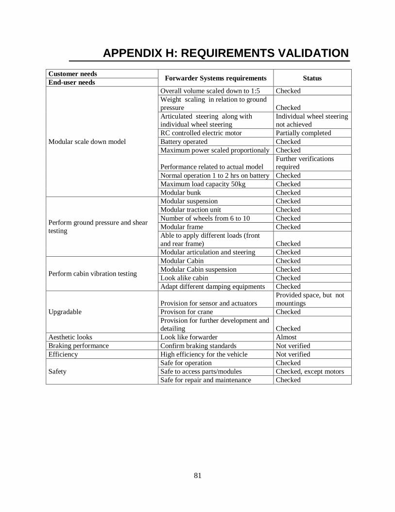
81
APPENDIX H: REQUIREMENTS VALIDATION
Customer needs Forwarder Systems requirements Status
End-user needs
Modular scale down model
Overall volume scaled down to 1:5 Checked
Weight scaling in relation to ground
pressure Checked
Articulated steering along with individual wheel steering
Individual wheel steering not achieved
RC controlled electric motor Partially completed
Battery operated Checked
Maximum power scaled proportionaly Checked
Performance related to actual model Further verifications required
Normal operation 1 to 2 hrs on battery Checked
Maximum load capacity 50kg Checked
Modular bunk Checked
Perform ground pressure and shear
testing
Modular suspension Checked
Modular traction unit Checked
Number of wheels from 6 to 10 Checked
Modular frame Checked
Able to apply different loads (front
and rear frame) Checked
Modular articulation and steering Checked
Perform cabin vibration testing
Modular Cabin Checked
Modular Cabin suspension Checked
Look alike cabin Checked
Adapt different damping equipments Checked
Upgradable
Provision for sensor and actuators
Provided space, but not
mountings
Provison for crane Checked
Provision for further development and detailing Checked
Aesthetic looks Look like forwarder Almost
Braking performance Confirm braking standards Not verified
Efficiency High efficiency for the vehicle Not verified
Safety
Safe for operation Checked
Safe to access parts/modules Checked, except motors
Safe for repair and maintenance Checked

82
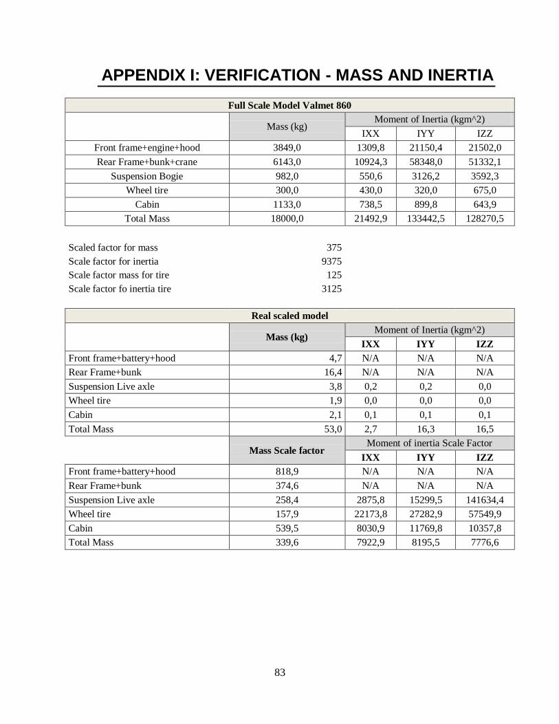
83
APPENDIX I: VERIFICATION - MASS AND INERTIA
Full Scale Model Valmet 860
Mass (kg) Moment of Inertia (kgm^2)
IXX IYY IZZ
Front frame+engine+hood 3849,0 1309,8 21150,4 21502,0
Rear Frame+bunk+crane 6143,0 10924,3 58348,0 51332,1
Suspension Bogie 982,0 550,6 3126,2 3592,3
Wheel tire 300,0 430,0 320,0 675,0
Cabin 1133,0 738,5 899,8 643,9
Total Mass 18000,0 21492,9 133442,5 128270,5
Scaled factor for mass 375
Scale factor for inertia 9375 Scale factor mass for tire 125
Scale factor fo inertia tire 3125
Real scaled model
Mass (kg) Moment of Inertia (kgm^2)
IXX IYY IZZ
Front frame+battery+hood 4,7 N/A N/A N/A
Rear Frame+bunk 16,4 N/A N/A N/A
Suspension Live axle 3,8 0,2 0,2 0,0
Wheel tire 1,9 0,0 0,0 0,0
Cabin 2,1 0,1 0,1 0,1
Total Mass 53,0 2,7 16,3 16,5
Mass Scale factor
Moment of inertia Scale Factor
IXX IYY IZZ
Front frame+battery+hood 818,9 N/A N/A N/A
Rear Frame+bunk 374,6 N/A N/A N/A
Suspension Live axle 258,4 2875,8 15299,5 141634,4
Wheel tire 157,9 22173,8 27282,9 57549,9
Cabin 539,5 8030,9 11769,8 10357,8
Total Mass 339,6 7922,9 8195,5 7776,6

84

85
APPENDIX J: SKOGBIL PICTURES

86
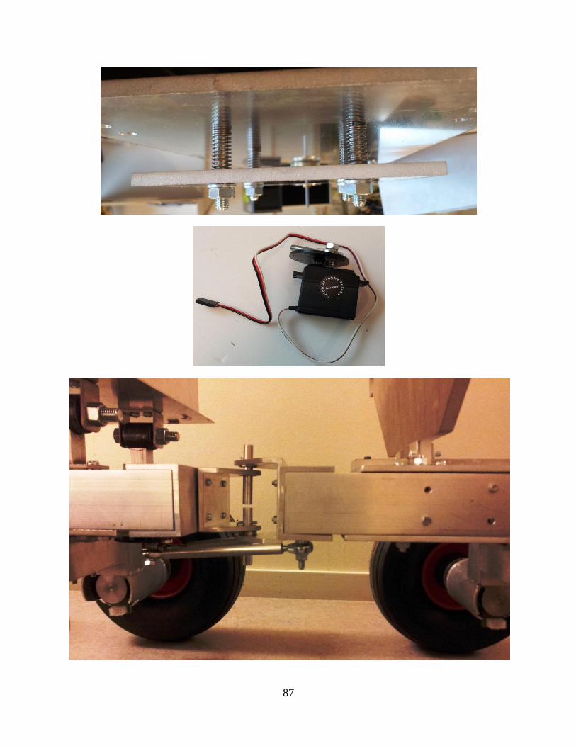
87

88