reinforcement mechanisms in mwcnt-filled polycarbonate · reinforcement mechanisms in...
TRANSCRIPT

COMPOSITES
www.elsevier.com/locate/compscitech
Composites Science and Technology 66 (2006) 1159–1170
SCIENCE ANDTECHNOLOGY
Reinforcement mechanisms in MWCNT-filled polycarbonate
A. Eitan a, F.T. Fisher b,*, R. Andrews c, L.C. Brinson b, L.S. Schadler a
a Materials Science and Engineering, Rensselaer Polytechnic Institute, Troy, NY 12180, USAb Department of Mechanical Engineering, Northwestern University, Evanston, IL 60208, USA
c Center for Applied Energy Research, University of Kentucky, Lexington, KY 40511, USA
Received 5 October 2005; accepted 5 October 2005Available online 5 December 2005
Abstract
The filler/matrix interface in fiber-reinforced polymer composites is critical in controlling load transfer from the matrix to the fiber,failure mechanisms, and degradation. It is not clear, however, how the mechanisms of load transfer in traditional composites apply tonanofiber-filled polymers. This paper is focused on understanding the reinforcement mechanisms in multiwalled carbon nanotube(MWCNT)/bisphenol-A polycarbonate (PC) composites. Strain dependent Raman spectroscopy shows that there is load transfer fromthe matrix to the nanotubes, and that the efficiency of the load transfer is improved by surface modification of the MWCNT. Dynamicmechanical analysis as well as electron microscopy reveals the presence of a large annular interphase region of immobilized polymer sur-rounding the embedded nanotubes. Micromechanical modeling of the elastic modulus of the composite that accounts for the limited loadtransfer to the interior shells of the MWCNT suggests this immobilized polymer provides an additional reinforcement mechanism that isunique for nano-filled composites.� 2005 Elsevier Ltd. All rights reserved.
Keywords: A. Nanostructures; A. Particle-reinforced composites; A. Polymer–matrix composites; B. Mechanical properties; C. Complex moduli
1. Introduction
Carbon nanotubes are an intriguing reinforcement forpolymers because of their unique mechanical propertiesand extremely large surface area per unit volume. Experi-ments [1–5] and calculations [6–13] show that nanotubeshave a modulus equal to or greater than the best graphitefibers, and strengths at least an order of magnitude higherthan typical graphite fibers. For example, measurement ofthe tensile properties of individual multi-walled carbonnanotubes (MWCNTs) obtained values of 11–63 GPa forthe tensile strength and 270–950 GPa for Young�s modulus[1]. For comparison, the modulus and strength of graphitefibers are 300–800 and 5 GPa, respectively.
0266-3538/$ - see front matter � 2005 Elsevier Ltd. All rights reserved.
doi:10.1016/j.compscitech.2005.10.004
* Corresponding author. Present address: Department of MechanicalEngineering, Stevens Institute of Technology, Hoboken, NJ 07030, USA.Tel.: +1 201 216 8913; fax: +1 201 216 8315.
E-mail address: [email protected] (F.T. Fisher).
In addition to their outstanding mechanical properties,the surface area per unit volume of nanotubes is much lar-ger than that of embedded graphite fibers. For example,30 nm diameter nanotubes have �150 times more surfacearea than 5 lm diameter fibers for the same filler volumefraction, such that the nanotube/matrix interfacial area ismuch larger than that in traditional fiber-reinforced com-posites. As shown in Fig. 1, this results in a much largerpercentage of interphase (also called the interaction zonein the literature) in nanotube-reinforced polymers whenthe ratio of the thickness t of the interphase versus theinclusion radius rf is plotted with respect to the volumefraction of the inclusion. Polymer within this interphaseregion has a structure and properties altered from that ofthe bulk polymer matrix due to interactions with theembedded nanotubes. This interphase region is differentin nature from the extensive work in the literature onfiber-reinforced composites describing engineered inter-faces, where fiber sizings (of often negligible volume frac-tion) are purposefully introduced to enhanced the

Fig. 1. Fraction of non-bulk polymer in the interphase region as afunction of volume fraction of fiber inclusion, where t is the interphasethickness and rf is the radius of the nanotube/fiber inclusion.
1160 A. Eitan et al. / Composites Science and Technology 66 (2006) 1159–1170
compatibility between the fibers and the polymer matrix(see the excellent review provided in [14]). In traditionalfiber composites this interfacial region is critical to controlthe load transfer from the matrix to the fiber and thus crit-ically influences both the modulus and fracture behavior ofthe composites [15–19]. However, due to the extreme sur-face area in nanotube-filled polymers the volume fractionof the interphase can be quite significant (in some instanceseven larger then that of the embedded nanotubes), suggest-ing an effective behavior more appropriately characterizedas that of a three phase composite. While the polymerproperties in the interphase are not well understood, it isclear that the mobility of the polymer is often altered in thisregion [20,21].
To predict the properties of nanotube-filled polymers, itis essential to understand the role of the nanotube–polymerinterface with regards to both load transfer and the forma-tion of the interphase region. Further, the realization ofoptimal effective mechanical properties for nanotube–poly-mer systems will likely be dependent on the ability to tailorboth the interface and interphase within the material.Thus, a number of researchers are investigating both cova-lent and non-covalent surface modifications of the nano-tubes to enhance the efficiency of load transfer to thenanotubes [22–28]. One particular challenge in this areais that the properties of the nanotube/polymer interfaceand of the polymer in the interaction zone are exceedinglydifficult to measure experimentally. For example, whileinterfacial strength is often determined in traditional com-posites using single fiber pull-out tests and fragmentationtests [29,30], only recently have these techniques been suc-cessfully applied to nanotube/polymer interfaces [31].Raman spectroscopy has also been used to measure loadtransfer from the matrix to the filler [32,33], but in the caseof nano-fillers has only been applied for qualitative com-parison [34]. The properties of the interphase are yetanother challenge, although previous work has probedthe influence of the local polymer environment on polymerchain mobility [35–42]. More recent work has addressed
the change in polymer chain mobility within the interphaseregion of nanotube–polymer composites based on theeffective viscoelastic behavior of macroscale samples, usingmicromechanical modeling techniques to study the local(nano-scale) properties of the interphase polymer [43,44].Consistent with the results presented here, others have alsosuggested that changes in the non-bulk polymer behaviormay provide an additional reinforcement mechanism inthese systems; for example, nanopullout work has sug-gested that the interphase can withstand stresses thatwould otherwise cause considerable yield in the bulk poly-mer [31]. There have been few studies, however, that corre-late the effect of the interface chemistry, the properties ofthe interphase polymer, and the macroscopic mechanicalproperties of the composite.
This paper presents a comprehensive study of the mech-anisms of nanotube reinforcement as a function of inter-face chemistry for MWCNT–polycarbonate composites.In particular, both load transfer within the compositeand non-bulk polymer interphase formation are character-ized using Raman spectroscopy, electron microscopy anddynamic mechanical analysis. This study indicates thatboth an increase in load transfer efficiency and a largernon-bulk polymer interphase result from surface modifica-tion of the MWCNTs. The correlation between the macro-mechanical properties of MWCNT-filled composites andthe molecular-level structure and behavior of the polymerchains presents new insights regarding the critical parame-ters influencing the mechanical behavior of these materials.
2. Experimental
2.1. Materials
The MWCNTs used here were produced by thermalchemical vapor deposition of a xylene–ferrocene feedstockat 700 �C in a quartz tube furnace [45]. The mean diameterof the MWCNTs was 31 nm, with a relatively broad distri-bution [46]. Lexan 121 (General Electric) was chosen forthe polymer matrix. Lexan 121 has a melt flow index of17.5, tensile yield stress of 61 MPa, and an elongation tobreak of 125%. The solvents tetrahydrofuran and methanol(analytical grade) were purchased from Aldrich and used asreceived.
2.2. Preparation of nanotube/polycarbonate composites
MWCNT were either used as received (AR) or surfaceepoxide-modified (EP). The details of the surface modifica-tion of the MWCNT and its characterization are describedelsewhere [28]. Briefly, the surface-modified nanotubeswere oxidized and then reacted with a hydroxyl-terminatedepoxide molecule. These covalently attached functionalgroups were then allowed to react with the polycarbonatematrix chains by transesterification [47,48] to cause tether-ing of polycarbonate chains onto the outer walls of theMWCNT.

A. Eitan et al. / Composites Science and Technology 66 (2006) 1159–1170 1161
MWCNT-reinforced PC samples were prepared by dis-persing the MWCNTs in tetrahydrofuran by bath ultra-sonication in a water ice bath (Fisher Scientific FS60) for3 h. PC pellets were dried at 125 �C for 2 h, followed by dis-solution in tetrahydrofuran. The MWCNT dispersion andthe PC solution were then mixed together and ultra-soni-cated for 1 more hour. The mixture was then dropped intostirred methanol causing precipitation of the compositematerial. The composite material was dried at 70 �C undervacuum for 16 h. To eliminate the risk of crystallization,dogbone samples were prepared using a DACA mini-injec-tion molding machine. The barrel temperature was 205 �Cand the mold temperature was 140 �C, and the injectionpressure was 862 kPa. The dimensions of the samples were25.0 mm · 4.0 mm · 1.5 mm (length · width · thickness).The composite samples prepared in this work containedAR-MWCNT concentrations of 2, 5 and 10 wt%, andEP-MWCNT concentration of 5 wt%. Pure PC sampleswere fabricated using an identical procedure as an experi-mental control.
Differential scanning calorimetry (DSC) verified thatstress crystallization was not induced within the samplesas noted by the absence of a melting endotherm. In addi-tion, MWNTs were removed from the bulk polymer matrixvia filtration through PTFE (100 lm pore size) using THFas a solvent. After removal from the nanocomposite theseMWNTs where still found to be coated by a polymersheathing, at which time they were again analyzed byDSC to examine whether polymer crystallization was pres-ent at the MWNTs surface. No evidence of such crystallinepolymer was detected, eliminating crystallinity as a causeof the behavior noted below.
2.3. Characterization
Tensile tests of dog-bone shaped samples wereconducted on an Instron 3042 equipped with an extensom-eter to record initial strains up to 10% during the runs.Samples were run at an extension rate of 0.5 mm/min.Strains larger than 10% were determined based on therelative displacement of the crossheads of the Instron. Atleast 3–5 samples were tested for each material, with theaverage values for these tests reported here with error barswhere appropriate.
Temperature and frequency dependent tests were com-pleted on a Rheometrics DMTA-V in tensile mode. Sampledimensions were 8 mm · 3.2 mm · 1 mm (length · width ·thickness). Two distinct dynamic mechanical tests weredone as described below. The first mode of testing con-sisted of temperature sweeps to measure the storage (E 0)and loss (E00) moduli as a function of temperature. In thesetests, the samples were subjected to a sinusoidal strain of0.03% (to ensure linear viscoelastic behavior) at a fre-quency of 1 Hz. The temperature scan rate for these testswas 2 �C/min. The loss tangent (tand) curve is defined asthe ratio of the loss modulus to the storage modulus.Finally, the glass transition temperature (Tg) of each sam-
ple is defined here as the peak of the loss modulus curve asa function of temperature. For the second mode of testing,frequency sweeps at different temperatures were run from0.2 to 200 Hz at five frequencies per decade, evenly spacedin log frequency space. After each isotherm the tempera-ture was raised and held constant for 5 min before the sub-sequent test. These isothermal runs were conducted from130 to 180 �C. The applied sinusoidal strain for the fre-quency domain tests was again 0.03%. At least three sam-ples of each type were tested. For clarity, only the mostrepresentative curve for each sample is shown; all testsshowed consistent sample behavior.
The viscoelastic behavior of nanotube–polymer compos-ites was characterized through the loss modulus and therelaxation spectra. These properties are directly related tochanges in molecular mobility. For example, if there is adistinct region of altered mobility, the relaxation spectraand loss modulus response of the material will change rel-ative to the viscoelastic response of the pure polymer; if thisnon-bulk polymer is characterized by reduced molecularmobility, peaks in the spectra and loss modulus willbroaden towards higher frequencies and higher tempera-tures, respectively. If the entire polymer matrix has effec-tively been altered by interactions with the nanotubesurface, the loss modulus and relaxation spectra will shifthorizontally with respect to that of the pure polymer.
Details of the analysis for obtaining the relaxation spec-tra were described elsewhere [43,49]. Briefly, the storage(E 0) and loss (E00) moduli can be expressed using a standardProny series as a function of the frequency x:
E0ðxÞ ¼ E1 þXN
j¼1
Ejx2
ð1=s2j Þ þ x2
; ð1Þ
E00ðxÞ ¼ E1 þXN
j¼1
ðEj=sjÞxð1=s2
j Þ þ x2; ð2Þ
where Ej are the Prony series coefficients and sj are the relax-ation times. Based on the response at different temperaturesover a relatively small frequency range (limited by theinstrument range of the DMA), time-temperature superpo-sition is used to obtain master curves for the storage andloss moduli at a particular reference temperature (150 �Cfor this work). Based on this master reference curve at a sin-gle temperature, the experimental storage and loss modulidata were fit to a 30 term Prony representation such thatthe Prony coefficients Ej were determined via a least-squaresfitting procedure assuming relaxation times sj evenly spacedand spanning the frequency range of the master referencecurve [50]. Once the Prony coefficients have been deter-mined for a given set of sj, the relaxation spectra H(s),which provides insight as to the relative significance ofrelaxation processes occurring at different time scales, canbe estimated using Alfrey�s approximation as [51]
HðsÞ �XN
j¼1
ssj
Eje� s
sj . ð3Þ

Fig. 2. Representative SEM image of the fracture surface for 5 wt%MWCNT in polycarbonate showing excellent dispersion.
1162 A. Eitan et al. / Composites Science and Technology 66 (2006) 1159–1170
Examination of the samples by electron microscopy wasconducted on composite fracture surfaces that wereobtained from the tensile-tested samples. In addition,probing of the nanocomposite fracture surface using ananomanipulator operating within a scanning electronmicroscope [52] was conducted as described elsewhere [46].
Raman spectroscopy was used to monitor the efficiencyof load transfer to the nanotubes. MWCNT-polymer dogbone samples (both AR and EP-MWCNT) were pressedinto �100 lm films using a Carver double plate press at205 �C. The film was then glued on a dog-bone shaped sub-strate made of Ultem. A strain gauge was glued on theUltem film for accurate measurement of the strain on thefilm. Polarized Raman spectroscopy (Reinshaw S2000)with 514 nm excitation was used to monitor the positionof the second order disorder peak as a function of theapplied composite strain. The slope of this Raman peakposition versus applied strain curve can be regarded as ameasure of the load transfer efficiency in the composite,where a steeper slope corresponds to more efficient loadtransfer.
In addition, we used polarized Raman spectroscopy tomeasure the degree of MWNT alignment in the unstrainedcomposites using procedures described by Gommans andco-workers [53]. With the polarizer and analyzer in parallel,the samples were rotated in 5� increments from 0� to 90�relative to the polarizer. Several points were measured oneach sample, and the data from two samples was averaged.The measurements were done at 10 mW and five accumula-tions of 10 s to provide a peak with high signal to noiseratio. The normalized intensity values (against the maxi-mum) were plotted against the angle of the sample. Itwas found that: 39% of the MWNT were in the range of0–22.5�, 25% of the MWNTs were from 22.5� to 45�,10% from 45� to 67.5� and 26% from 67.5� to 90�. Thus,while there was some processing-induced alignment dueto the injection molding of the samples, the alignmentwas rather minimal and similar for all the compositestested. Thus, one can conclude that processing-inducedalignment is not responsible for the interphase effects char-acterized in this paper.
3. Results
3.1. Mechanical properties
The quality of the MWCNT dispersion in the compositewas examined by field emission scanning electron micros-copy of the fracture surface of the tensile-tested specimens.Fig. 2 shows a representative example of the homogeneousdispersions that were achieved for the AR and EP-MWCNT/PC composites. The good dispersion is necessaryfor optimal mechanical properties and insures maximumsurface area for nanotube/polymer interaction. Fig. 3(a)shows typical stress–strain curves for the AR-MWCNT/PC composites at several MWCNT concentrations. Anincrease in the elastic modulus and the yield stress was
observed with increasing MWCNT content. The values ofthe elastic modulus as a function of the nanotube concen-tration, both for AR-MWCNT and EP-MWCNT, are pre-sented graphically in Fig. 3(b). A 70% increase is seen dueto incorporation of 5 wt% AR-MWCNT compared to purePC moduli. A higher increase is seen for the surface mod-ified MWCNT (95% increase compared to pure PC at5 wt% loading). Table 1 summarizes the modulus, yieldstress, and strain-to-failure for each composite sample.Note that the yield stress increased and the strain-to-failuredecreased for the EP surface-modified samples. While thevalues of Young�s modulus and the yield strain were char-acterized by very small scatter in the data, the values forthe strain to failure showed a much more significant spreadin measured values. While these initial results suggest thatthe strain to failure values reported for the nanocompositesamples were distinct based on the nanotube treatment,this topic will be the subject of future investigation.
3.2. Viscoelastic properties
The DMTA results of the temperature sweeps for thedifferent samples are shown in Fig. 4. The storage moduluscurves (Fig. 4(a)) show an increase in the modulus in theglassy state region as a function of the AR-MWCNTconcentration, as expected from the results of the room-temperature elastic tests. Further, the high-temperaturerubbery (above Tg) storage modulus for 10 wt% AR-MWCNT/PC composites is an order of magnitude higherthan unfilled PC. The glass transition temperature (definedhere as the peak of the loss modulus curve, Fig. 4(b)) seemsto shift slightly to higher temperatures upon furtherloading of AR-MWCNTs. However, of greater interest isthe broadening of the loss modulus curve as the concentra-tion of the AR-MWCNT increases. Specifically, thebroadening is more pronounced in the region above Tg ofthe pure polycarbonate sample. The loss factor peak of
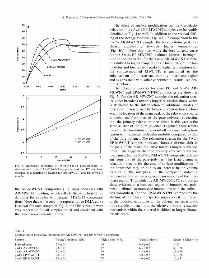
Fig. 3. Mechanical properties of MWCNT-filled polycarbonate: (a)stress–strain curves of AR-MWCNT composites and pure PC; (b) elasticmodulus as a function of loading for AR-MWCNT and EP-MWCNTsamples.
A. Eitan et al. / Composites Science and Technology 66 (2006) 1159–1170 1163
the AR-MWCNT composites (Fig. 4(c)) decreases withAR-MWCNT loading, which reflects the reduction in thedamping for samples with greater MWCNT concentra-tions. Note that while only one representative DMA curveis shown for each sample in Fig. 4, the DMA results werevery repeatable for all samples tested and consistent withthe conclusions presented above.
Table 1Comparison of mechanical properties for AR-MWCNT and EP-MWCNT co
Sample Young�s modulus (GPa) Yield s
Polycarbonate 2.0 ± 0.1 592 wt% AR-MWCNT 2.6 ± 0.1 675 wt% AR-MWCNT 3.3 ± 0.1 702 wt% EP-MWCNT 2.8 ± 0.1 695 wt% EP-MWCNT 3.8 ± 0.1 78
The effect of surface modification on the viscoelasticbehavior of the 5 wt% EP-MWCNT samples can be readilyidentified in Fig. 4 as well. In addition to the vertical shift-ing of the storage modulus (Fig. 4(a)) in comparison to the5 wt% AR-MWCNT sample, the loss modulus peak hasshifted significantly towards higher temperatures(Fig. 4(b)). Note also that while the loss tangent curvefor the 5 wt% EP-MWCNT is almost identical in magni-tude and shape to that for the 5 wt% AR-MWCNT sample,it is shifted to higher temperatures. This shifting of the lossmodulus and loss tangent peaks to higher temperatures forthe surface-modified MWCNTs is attributed to theenhancement of a restricted-mobility interphase regionand is consistent with other experimental results (see Sec-tion 4 below).
The relaxation spectra for pure PC and 5 wt% AR-MCWNT and EP-MWCNT/PC composites are shown inFig. 5. For the AR-MWCNT samples the relaxation spec-tra curve broadens towards longer relaxation times, whichis attributed to the introduction of additional modes ofrelaxation characterized by longer relaxation times. How-ever, the location of the main peak of the relaxation spectrais unchanged from that of the pure polymer, suggestingthat the primary relaxation mechanism in this case is thesame as that of the pure polymer. Together, these resultsindicate the formation of a non-bulk polymer interphaseregion with restricted molecular mobility compared to thatof the pure polymer. The relaxation spectra for the 5 wt%EP-MWCNT sample, however, shows a distinct shift inthe peak of the relaxation curve towards longer relaxationtimes. This suggests that the primary effective relaxationmechanism for the 5 wt% EP-MWCNT composite is differ-ent from that of the pure polymer. This large change inrelaxation spectra for the case of surface modification ofthe nanotubes may be due to an increase in the volumefraction of the interphase in the composite and/or adecrease in the effective polymer chain mobility of the inter-phase region. Thus while the AR-MWCNT/PC compositesshow evidence of a localized region of immobilized poly-mer (attributed to nanoscale interactions with the embed-ded nanotubes), for the EP-MWCNT/PC composites theshifting of the relaxation spectra suggests that the impactof the modified nanotubes on the polymer matrix is muchmore significant, such that the effective primary relaxationmechanism within the material is shifted to longer charac-teristic times.
mposites
tress (MPa) Yield strain(%) Strain to failure (%)
6.5 ± 0.2 >1006.5 ± 0.2 80 ± 304.8 ± 0.2 25 ± 105.0 ± 0.2 50 ± 204.0 ± 0.2 10 ± 3
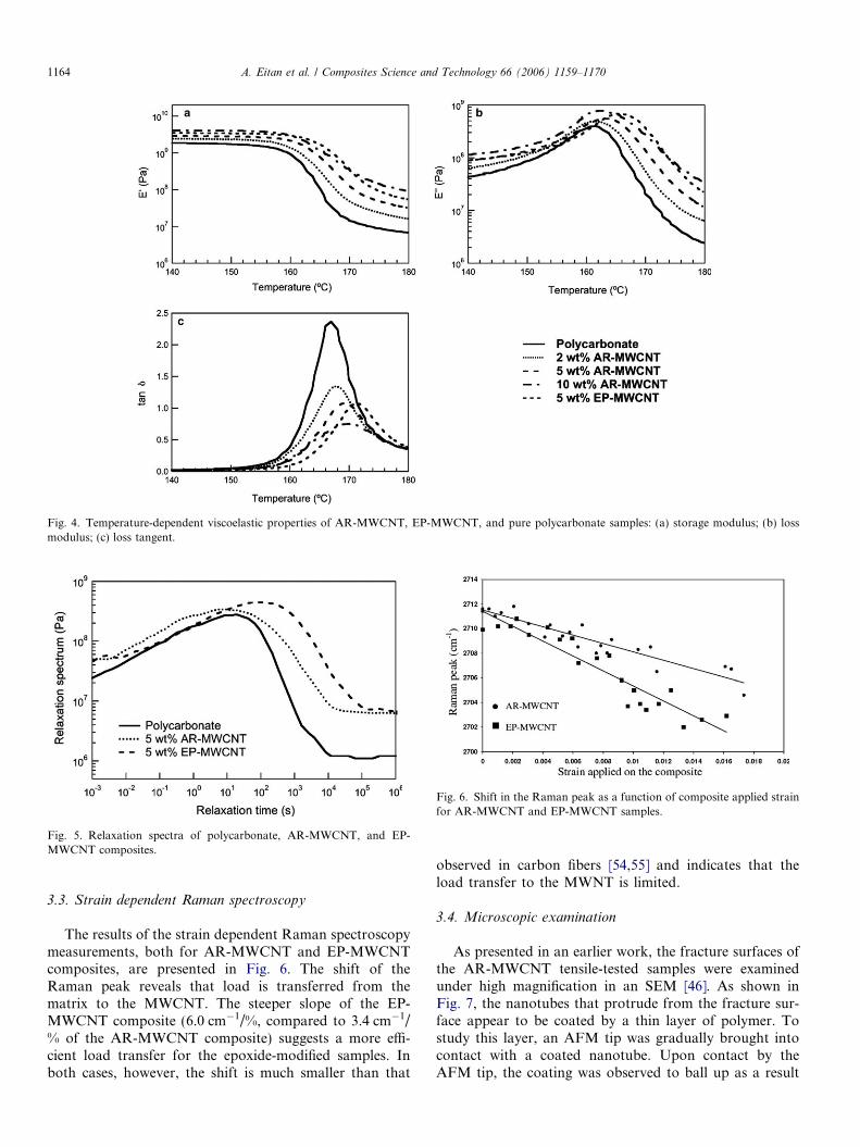
Fig. 4. Temperature-dependent viscoelastic properties of AR-MWCNT, EP-MWCNT, and pure polycarbonate samples: (a) storage modulus; (b) lossmodulus; (c) loss tangent.
Fig. 5. Relaxation spectra of polycarbonate, AR-MWCNT, and EP-MWCNT composites.
Fig. 6. Shift in the Raman peak as a function of composite applied strainfor AR-MWCNT and EP-MWCNT samples.
1164 A. Eitan et al. / Composites Science and Technology 66 (2006) 1159–1170
3.3. Strain dependent Raman spectroscopy
The results of the strain dependent Raman spectroscopymeasurements, both for AR-MWCNT and EP-MWCNTcomposites, are presented in Fig. 6. The shift of theRaman peak reveals that load is transferred from thematrix to the MWCNT. The steeper slope of the EP-MWCNT composite (6.0 cm�1/%, compared to 3.4 cm�1/% of the AR-MWCNT composite) suggests a more effi-cient load transfer for the epoxide-modified samples. Inboth cases, however, the shift is much smaller than that
observed in carbon fibers [54,55] and indicates that theload transfer to the MWNT is limited.
3.4. Microscopic examination
As presented in an earlier work, the fracture surfaces ofthe AR-MWCNT tensile-tested samples were examinedunder high magnification in an SEM [46]. As shown inFig. 7, the nanotubes that protrude from the fracture sur-face appear to be coated by a thin layer of polymer. Tostudy this layer, an AFM tip was gradually brought intocontact with a coated nanotube. Upon contact by theAFM tip, the coating was observed to ball up as a result
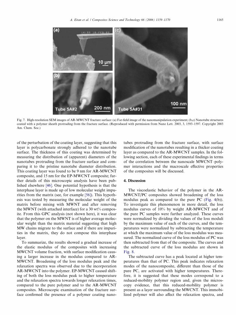
Fig. 7. High-resolution SEM images of AR-MWCNT fracture surface: (a) Far-field image of the nanomanipulation experiment; (b,c) Nanotube structurescoated with a polymer sheath protruding from the fracture surface. (Reproduced with permission from Nano Lett. 2003, 3, 1593–1597. Copyright 2003Am. Chem. Soc.)
A. Eitan et al. / Composites Science and Technology 66 (2006) 1159–1170 1165
of the perturbation of the coating layer, suggesting that thislayer is polycarbonate strongly adhered to the nanotubesurface. The thickness of this coating was determined bymeasuring the distribution of (apparent) diameters of thenanotubes protruding from the fracture surface and com-paring it to the pristine nanotube diameter distribution.This coating layer was found to be 9 nm for AR-MWCNTcomposite, and 15 nm for the EP-MWCNT composite; fur-ther details of this microscopic analysis have been pub-lished elsewhere [46]. One potential hypothesis is that theinterphase layer is made up of low molecular weight impu-rities from the matrix (see, for example [56]). This hypoth-esis was tested by measuring the molecular weight of thematrix before mixing with MWNT and after removingthe MWNT (with attached interface) for a 30 wt% compos-ite. From this GPC analysis (not shown here), it was clearthat the polymer on the MWNT is of higher average molec-ular weight than the matrix material suggesting that highMW chains migrate to the surface and if there are impuri-ties in the matrix, they do not compose this interphaselayer.
To summarize, the results showed a gradual increase ofthe elastic modulus of the composites with increasingMWCNT volume fraction, with surface modification caus-ing a larger increase in the modulus compared to AR-MWCNT. Broadening of the loss modulus peak and therelaxation spectra was observed due to the incorporationAR-MWCNT into the polymer. EP-MWCNT caused shift-ing of both the loss modulus peak to higher temperatureand the relaxation spectra towards longer relaxation times,compared to the pure polymer and to the AR-MWCNTcomposites. Microscopic examination of the fracture sur-face confirmed the presence of a polymer coating nano-
tubes protruding from the fracture surface, with surfacemodification of the nanotubes resulting in a thicker coatinglayer as compared to the AR-MWCNT samples. In the fol-lowing section, each of these experimental findings in termsof the correlation between the nanoscale MWCNT–poly-mer interactions and the macroscale effective propertiesof the composites will be discussed.
4. Discussion
The viscoelastic behavior of the polymer in the AR-MWCNT/PC composites showed broadening of the lossmodulus peak as compared to the pure PC (Fig. 4(b)).To investigate this phenomenon in more detail, the lossmodulus curves of 10% by weight AR-MWCNT and ofthe pure PC samples were further analyzed. These curveswere normalized by dividing the values of the loss moduliby the maximum value of each of the curves, and the tem-peratures were normalized by subtracting the temperatureat which the maximum value of the loss modulus was mea-sured. The normalized curve of the loss modulus of PC wasthen subtracted from that of the composite. The curves andthe subtracted curve of the loss modulus are shown inFig. 8.
The subtracted curve has a peak located at higher tem-peratures than that of PC. This peak indicates relaxationmodes of the nanocomposite, different than those of thepure PC, are activated with higher temperatures. There-fore, it is suggested that these modes correspond to areduced-mobility polymer region and, given the micros-copy evidence, that this reduced-mobility polymer ispresent as a layer surrounding the MWCNT. This immobi-lized polymer will also affect the relaxation spectra, and
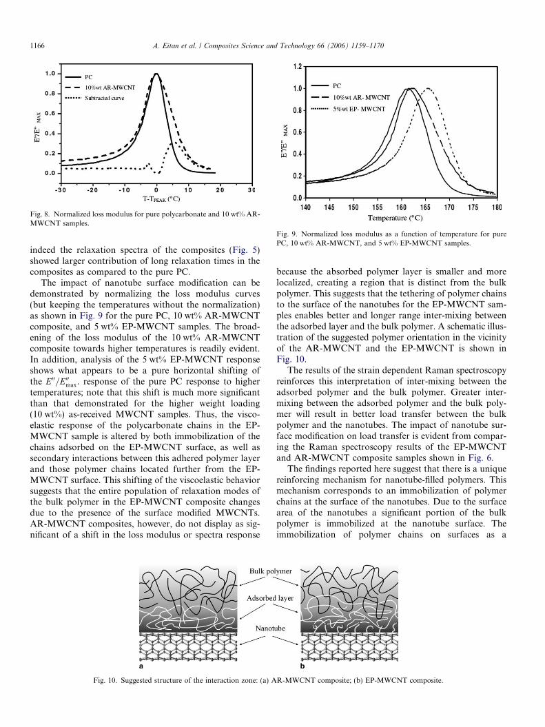
Fig. 8. Normalized loss modulus for pure polycarbonate and 10 wt% AR-MWCNT samples.
Fig. 9. Normalized loss modulus as a function of temperature for purePC, 10 wt% AR-MWCNT, and 5 wt% EP-MWCNT samples.
1166 A. Eitan et al. / Composites Science and Technology 66 (2006) 1159–1170
indeed the relaxation spectra of the composites (Fig. 5)showed larger contribution of long relaxation times in thecomposites as compared to the pure PC.
The impact of nanotube surface modification can bedemonstrated by normalizing the loss modulus curves(but keeping the temperatures without the normalization)as shown in Fig. 9 for the pure PC, 10 wt% AR-MWCNTcomposite, and 5 wt% EP-MWCNT samples. The broad-ening of the loss modulus of the 10 wt% AR-MWCNTcomposite towards higher temperatures is readily evident.In addition, analysis of the 5 wt% EP-MWCNT responseshows what appears to be a pure horizontal shifting ofthe E00=E00max. response of the pure PC response to highertemperatures; note that this shift is much more significantthan that demonstrated for the higher weight loading(10 wt%) as-received MWCNT samples. Thus, the visco-elastic response of the polycarbonate chains in the EP-MWCNT sample is altered by both immobilization of thechains adsorbed on the EP-MWCNT surface, as well assecondary interactions between this adhered polymer layerand those polymer chains located further from the EP-MWCNT surface. This shifting of the viscoelastic behaviorsuggests that the entire population of relaxation modes ofthe bulk polymer in the EP-MWCNT composite changesdue to the presence of the surface modified MWCNTs.AR-MWCNT composites, however, do not display as sig-nificant of a shift in the loss modulus or spectra response
Fig. 10. Suggested structure of the interaction zone: (a) A
because the absorbed polymer layer is smaller and morelocalized, creating a region that is distinct from the bulkpolymer. This suggests that the tethering of polymer chainsto the surface of the nanotubes for the EP-MWCNT sam-ples enables better and longer range inter-mixing betweenthe adsorbed layer and the bulk polymer. A schematic illus-tration of the suggested polymer orientation in the vicinityof the AR-MWCNT and the EP-MWCNT is shown inFig. 10.
The results of the strain dependent Raman spectroscopyreinforces this interpretation of inter-mixing between theadsorbed polymer and the bulk polymer. Greater inter-mixing between the adsorbed polymer and the bulk poly-mer will result in better load transfer between the bulkpolymer and the nanotubes. The impact of nanotube sur-face modification on load transfer is evident from compar-ing the Raman spectroscopy results of the EP-MWCNTand AR-MWCNT composite samples shown in Fig. 6.
The findings reported here suggest that there is a uniquereinforcing mechanism for nanotube-filled polymers. Thismechanism corresponds to an immobilization of polymerchains at the surface of the nanotubes. Due to the surfacearea of the nanotubes a significant portion of the bulkpolymer is immobilized at the nanotube surface. Theimmobilization of polymer chains on surfaces as a
R-MWCNT composite; (b) EP-MWCNT composite.
A. Eitan et al. / Composites Science and Technology 66 (2006) 1159–1170 1167
fundamental phenomenon has been studied extensively[40,57,58]. Note that the immobilization of polymer onnanotube surfaces has been recently detected in other poly-mer composite systems as well. For example, Cadek et al.[59] found a thin layer of polyvinyl alcohol coating nano-tubes protruding from the fracture surface of the compos-ite, while Wong et al. [60] found polystyrene well coats theembedded nanotubes.
While immobilization can also occur on traditionalfibers [56], for nanotube-reinforced composite samplesthe volume of immobilized polymer comprising the inter-phase region is significant and cannot be neglected fromthe standpoint of effective composite properties predic-tions. This is demonstrated in Fig. 1, where the percent-age of non-bulk polymer in the interphase region canbe determined based on the ratio of the fiber (nanotube)radius rf versus the thickness t of this interphase region.For micron-sized fibers, the thickness of this interphaseregion is comparably small such that the ratio t/rf is smalland the percentage of interphase polymer is negligible.However, for nanotube-reinforced polymers where theratio t/rf is much larger, a greater portion of the polymerwithin the sample is characterized by this non-bulkbehavior and must be accounted for explicitly in compos-ite property predictions. Note that for nanotube diame-ters smaller than the 30-nm MWCNTs used here(including single-walled carbon nanotubes), the presenceof this non-bulk polymer interphase will be even morepronounced.
The immobilized polymer possesses different mechani-cal properties than the bulk polymer because of therestricted mobility introduced by interaction with thenanotube surface. Thus, this immobilized polymer canbe regarded as a third phase in the composite and needsto be treated separately in mechanical modeling of effec-tive properties. While the mechanical properties of thecomposite will be influenced by the mechanical propertiesof the both the MWCNTs and the immobilized layer, theproperties of the interphase polymer are unknown. How-ever, one can use micromechanical modeling to estimatethe properties of this interphase region based on the mea-sured effective properties of the nanotube–polymer com-posite [44]. This analysis also provides a framework toassess the influence of load transfer in MWNTs on com-posite properties in terms of an effective NT volumefraction.
The micromechanical model chosen for this analysis isthe Mori–Tanaka method, which is a popular tool for effec-tive property predictions of multiphase composites and isdescribed in more detail elsewhere [61–63]. Briefly, theeffective composite stiffness C is given as
C ¼XN�1
r¼0
frfCrAdilr g
! XN�1
r¼0
frfAdilr g
!�1
; ð4Þ
where Cr and fr are the stiffness and volume fraction of therth phase (the matrix is denoted as phase 0), Adil
r is the di-
lute strain concentration tensor of the rth phase, {} denotesan appropriate orientational average of the tensor quanti-ties, and parameters in bold type represent tensor quanti-ties. For ellipsoidal inclusions, the dilute strainconcentration tensor is given analytically as
Adilr ¼ ½Iþ SrC
�10 ðCr � C0Þ��1 ð5Þ
where Sr is the standard Eshelby tensor [64] and by defini-tion Adil
0 ¼ I. While treating the composite as a three-phasecomposite with two distinct inclusion phases (MWCNTsand polymer interphase) does not account for the annulargeometry of the interphase surrounding the MWCNTs, theerror introduced by this simplification is small [65]. Thus,here the MWCNT and polymer interphase componentswill be separately modeled using the Eshelby tensor for infi-nitely long circular cylinders.
To implement the micromechanical model one mustaddress the appropriate modulus and volume fractionthat should be assigned to the MWCNTs. In the litera-ture, experimental results for MWCNT modulus varyfrom 270 to 950 GPa [1] and 450 ± 230 GPa [66], respec-tively, suggesting that assuming a modulus value of600 GPa for the MWCNTs is appropriate. While itmay seem acceptable to use the occupied (total) volumefraction of the MWCNTs (where the rule-of-thumb con-version factor of 2:1 is used to convert weight fraction tovolume fraction of MWCNTs), due to poor load transferbetween the adjacent shells in MWCNTs the moduli val-ues determined in the experimental papers is calculatedbased on only the outer shell of the MWCNT. Thus,one may argue that a more appropriate selection forthe effective volume fraction of MWCNTs in the sampleassigns the nanotube modulus to a volume fraction basedon the volume of the outer shell only (see also, for exam-ple [67]). The volume of the outer shell Vos can be relatedto the total occupied volume of the MWCNT Vocc suchthat Vos/Vocc = 4t/D, where the thickness of the outershell t is assumed to equal the 0.34-nm interlayer spacingin graphite.
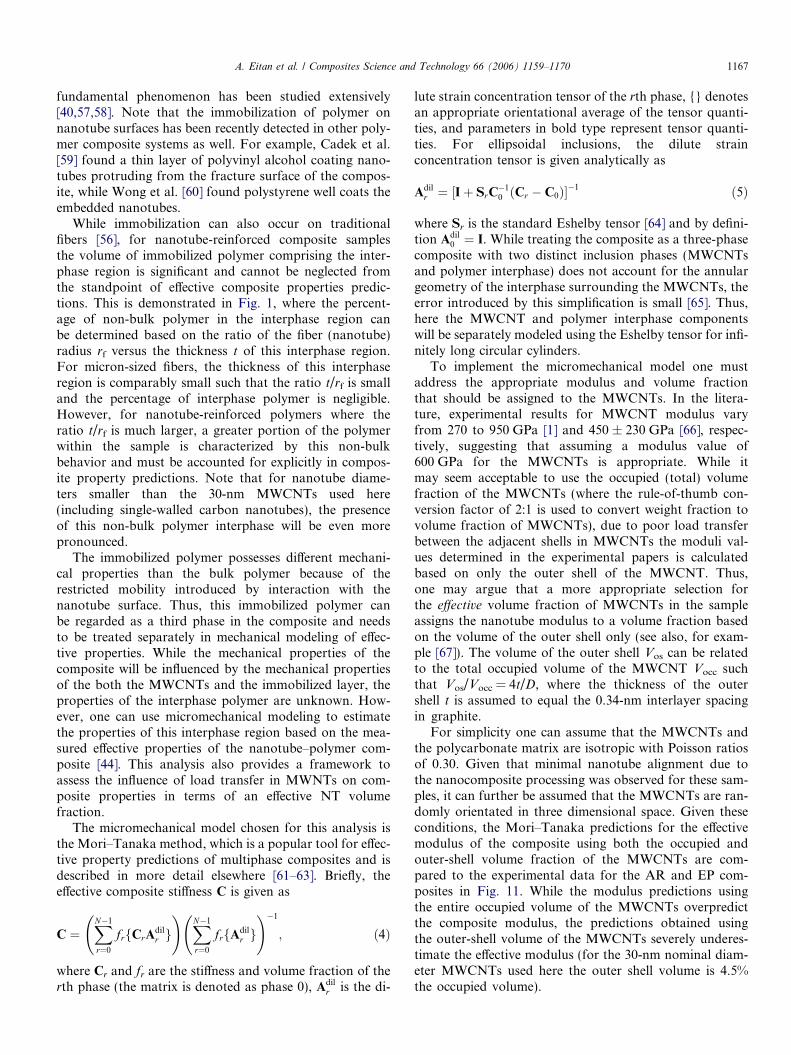
For simplicity one can assume that the MWCNTs andthe polycarbonate matrix are isotropic with Poisson ratiosof 0.30. Given that minimal nanotube alignment due tothe nanocomposite processing was observed for these sam-ples, it can further be assumed that the MWCNTs are ran-domly orientated in three dimensional space. Given theseconditions, the Mori–Tanaka predictions for the effectivemodulus of the composite using both the occupied andouter-shell volume fraction of the MWCNTs are com-pared to the experimental data for the AR and EP com-posites in Fig. 11. While the modulus predictions usingthe entire occupied volume of the MWCNTs overpredictthe composite modulus, the predictions obtained usingthe outer-shell volume of the MWCNTs severely underes-timate the effective modulus (for the 30-nm nominal diam-eter MWCNTs used here the outer shell volume is 4.5%the occupied volume).
Fig. 11. Comparison of micromechanical predictions and experimentalmeasurements of the MWCNT-PC moduli. Vocc and Vos (Vos = 0.045Vocc)are the occupied and outer-shell volume of the MWCNTs, respectively.
1168 A. Eitan et al. / Composites Science and Technology 66 (2006) 1159–1170
In actuality the appropriate volume fraction of nano-tubes to use for this analysis is intermediate these twoextremes. While the outer shell volume fraction (Vos) mayaccount for the negligible contribution of the inner shellsof MWCNTs loaded in pure tension, within the compositethe randomly oriented MWCNTs experience a complexstress state (including bending and shear, further compli-cated by the non-straight actual morphology of the NTs[68–70]), where the inner shells may be expected to contrib-ute to the reinforcement provided by the MWCNTs. Like-wise, assigning the nanotube modulus to the entire volume(Vocc) of the MWCNTs in the composite does not accountfor the weak interactions between shells in a MWCNT andis clearly an overestimate of contributing volume fractionfor tubes experiencing significant tensile loads. As a com-promise one can consider a simple model where theMWCNTs are assumed to be unidirectionally aligned inthe direction of loading and only the outer-shell volume(Vos) of the MWCNT is used. This choice will provide aneffective modulus prediction intermediate to the previoustwo extremes. This prediction is also shown in Fig. 11.The modulus predictions generated in this manner areapproximately equal to using 25% of the occupied nano-tube volume (25%Vocc) for the case of three-dimensionalrandomly orientated MWCNTs.
While the complex nature of the nanotube morphologyin the composite complicates the analysis, one can arguethat assuming that all of the nanotubes are aligned withthe axis of loading should provide an upper bound predic-tion to the composite properties. Yet this last calculationdone using the Vos lies below the experimental data. How-ever, to this point, the modeling has only considered atwo-phase composite consisting of the MWCNTs and thepolycarbonate matrix. As discussed earlier, characteriza-tion of this composite system has detailed the presence ofa non-bulk polymer interphase that exhibits reduced poly-mer mobility due to strong interactions with embedded
nanotubes. The micromechanical modeling also providesa route to obtain a first approximation for the modulus ofthe interphase region by solving an inverse problem. Toillustrate this point, one can determine the interphase mod-ulus values that fit the high loading (5 wt%) experimentaldata using a three-phase Mori-Tanaka analysis. Taking30 nm as the mean diameter of the MWCNTs and 9 and15 nm to be the nominal interphase thicknesses found forthe AR and EP samples, the ratio of the interphase volumefraction to the occupied MWCNT volume fraction is foundto be 1.56 and 3.0 for the AR and EP samples, respectively.Using Vocc = 25% for the effective occupied volume fractionof the three-dimensional randomly orientated MWCNTs(to match the results of the unidirectionally aligned,outer-shell model discussed above) and the appropriateinterphase volume fractions, interphase moduli of 75 and70 GPa are found to match the experimental data for theAR and EP samples, respectively.
Modeling nanotube composites is inherently difficultdue to unknown complexities within the material system,simplifying assumptions that must be made, and the diffi-culty of modeling at both appropriate length and timescales. Some of the key modeling limitations at presentinclude: proper consideration of the reinforcement pro-vided by the MWCNT inner shells, explicit impact of func-tionalization on the nanotube mechanical properties,incorporation of non-uniform properties throughout thegradient interphase, impact of the inter-connected networkstructure of the embedded nanotubes on effective proper-ties, and analysis of the bonding and load transfer effi-ciency of these systems. These issues all create difficultiesin quantitative interpretation and prediction of the effectivemechanical behavior of nanotube–polymer composites.Due to these limitations, the model presented in this papershould be considered a first approximation and be consid-ered qualitative. From this view, the existence of an inter-phase zone with modulus increased an order ofmagnitude (compared to the modulus of bulk polycarbon-ate) is reasonable and consistent with the increases in mod-ulus measured for oriented polymers. As computationalmolecular techniques are developed it is envisioned thatresults from such simulations will serve as valuable inputparameters into higher-scale modeling efforts such as theone presented here. Thus as better models of the mechani-cal behavior of embedded MWCNTs and their interactionswith the local polymer chains for long time scales are devel-oped, more accurate approximations of the interphasemodulus based on macroscale experimental testing will beachievable.
5. Summary
The focus of this paper was the study of the reinforce-ment mechanisms of MWCNT-filled polymers. A reinforce-ment mechanism, unique for nano-filled polymercomposites, is suggested from this work. Immobilizationof polymer chains on the surface of the nanotubes causes

A. Eitan et al. / Composites Science and Technology 66 (2006) 1159–1170 1169
mechanical stiffening of this interphase region and thus canbe considered as an additional reinforcing component in thecomposite. The large available nanotube surface area withinthe nanotube–polymer composite results in a significantregion of immobilized polymer; the extent of this interphaseregion can be made larger via appropriate surface modifica-tion of the MWCNTs as observed in high resolution SEMimaging of the composite fracture surfaces. Analysis ofthe viscoelastic properties of these composites, and in par-ticular the effective relaxation spectra of the samples, indi-cates differences in the morphology and properties ofpolymer within this non-bulk interphase region. Specifi-cally, enhanced inter-mixing in EP-MWCNT compositesallows better load transfer, and therefore improvedmechanical properties, as compared to AR-MWCNT com-posites. Thus the immobilization of the polymer in the inter-phase region provides an additional reinforcement of thecomposite, which for the case of nanotube–polymer com-posites can be significant given the considerable fractionof this altered polymer in the nanotube-reinforced polymer.
The ability to control the properties of the immobilizedpolymer layer, and the interactions between this layer andthe bulk polymer, will affect the load transfer mechanismsfrom the bulk polymer to the reinforcing components inthe composites. The thickness of the adsorbed polymerlayer, its properties, and the nature of interactions withthe bulk polymer chains are parameters that have to becontrolled in order to optimize the reinforcement efficiencyin nanotube–polymer composite materials.
Acknowledgments
A.E. and L.S.S. acknowledge the support of the USArmy SBCCOM, Natick Soldier Center as well as theNanoscale Science and Engineering Initiative of the Na-tional Science Foundation under NSF Award No. DMR-0117792. F.T.F and L.C.B appreciate the grant supportfrom the NASA University Research, Engineering andTechnology Institute on Bio Inspired Materials (BIMat)under Award No. NCC1-02037 and the NASA LangleyResearch Center Computational Materials: Nanotechnol-ogy Modeling and Simulation Program. R.A. thanks theMRSEC Advanced Carbon Materials Center (DMR-98.9686) for support.
References
[1] Yu M-F, Lourie O, Dyer M, Moloni K, Kelly TF, Ruoff RS. Strengthand breaking mechanism of multiwalled carbon nanotubes undertensile load. Science 2000;287:637.
[2] Yu M-F, Files BS, Arepalli S, Ruoff RS. Tensile loading of ropes ofsingle wall carbon nanotubes and their mechanical properties. PhysRev Lett 2000;84(24):5552.
[3] Demczyk BG, Wang YM, Cumings J, Hetman M, Han W, Zettl A,et al. Direct mechanical measurement of the tensile strength andelastic modulus of multiwalled carbon nanotubes. Mater Sci Eng A2002;334:173.
[4] Krishnan A, Dujardin E, Ebbesen TW, Yianilos PN, Treacy MMJ.Young�s modulus of single-walled nanotubes. Phys Rev B1998;58(20):14103.
[5] Lourie O, Wagner HD. Evaluation of Young�s modulus of carbonnanotubes by micro-Raman spectroscopy. J Mater Res1998;13(9):2418.
[6] Treacy MMJ, Ebbesen TW, Gibson JM. Exceptionally high young�smodulus observed for individual carbon nanotubes. Nature1996;381:678.
[7] Gao G, Cagin T, Goddard III WA. Energetics, structure, mechanicaland vibrational properties of single-walled carbon nanotubes. Nano-technology 1998;9:184.
[8] Lu JP. Elastic properties of carbon nanotubes and nanoropes. PhysRev Lett 1997;79(7):1297.
[9] Sanchez-Portal S, Artacho E, Soler JM, Rubio A, Ordejon P. Abinitio structural, elastic, and vibrational properties of carbon nano-tubes. Phys Rev B 1999;59(19):12678.
[10] Yakobson B, Brabec C, Bernholc J. Nanomechanics of carbon tubes:Instabilities beyond linear response. Phys Rev Lett 1996;76(14):2511.
[11] Popov VN, Van Doren VE, Balkanski M. Elastic properties of single-walled carbon nanotubes. Phys Rev B 2000;61(4):3078.
[12] Belytschko T, Xiao SP, Schatz GC, Ruoff R. Atomistic simulations ofnanotube fracture. Phys Rev B 2002;65(23):235430.
[13] Zhou X, Zhou JJ, Ou-Yang ZC. Strain energy and Young�s modulusof single-wall carbon nanotubes calculated from electronic energy-band theory. Phys Rev B 2000;62(20):13692.
[14] Kim JK, Mai YW. Engineered interfaces in fibre reinforced compos-ites. Oxford (UK): Elsevier; 1998.
[15] Gamstedt EK, Skrifvars M, Jacobsen TK, Pyrz R. Synthesis ofunsaturated polyesters for improved interfacial strength in carbonfibre composites. Composites Part A 2002;33(9):1239.
[16] Montes-Moran MA, Young RJ. Raman spectroscopy study of HMcarbon fibres: Effect of plasma treatment on the interfacial propertiesof single fibre/epoxy composites – Part I: Fibre characterisation.Carbon 2002;40(6):845.
[17] Montes-Moran MA, Martinez-Alonso A, Tascon JMD, Paiva MC,Bernardo CA. Effects of plasma oxidation on the surface andinterfacial properties of carbon fibres/polycarbonate composites.Carbon 2001;39(7):1057.
[18] Lopattananon N, Kettle AP, Tripathi D, Beck AJ, Duval E, FranceRM, et al. Interface molecular engineering of carbon-fiber compos-ites. Composites Part A 1999;30(1):49.
[19] Schadler LS, Galiotis C. Fundamentals and applications of micro-Raman spectroscopy to strain-measurements in fiber-reinforcedcomposites. Int Mater Rev 1995;40(3):116.
[20] Starr FW, Schroder TB, Glotzer SC. Molecular dynamics simulationof a polymer melt with a nanoscopic particle. Macromolecules2002;35(11):4481.
[21] Smith GD, Bedrov D, Li L, Byutner O. A molecular dynamicssimulation study of the viscoelastic properties of polymer nanocom-posites. J Chem Phys 2002;117(20):9478.
[22] O�Connell MJ, Boul P, Ericson LM, Huffman C, Wang YH, Haroz E,et al. Reversible water-solubilization of single-walled carbon nano-tubes by polymer wrapping. Chem Phys Lett 2001;342(3–4):265.
[23] Hill DE, Lin Y, Rao AM, Allard LF, Sun YP. Functionalization ofcarbon nanotubes with polystyrene. Macromolecules2002;35(25):9466.
[24] Hamon MA, Hu H, Bhowmik P, Niyogi S, Zhao B, Itkis ME, et al.End-group and defect analysis of soluble single-walled carbonnanotubes. Chem Phys Lett 2001;347(1–3):8.
[25] Baker SE, Cai W, Lasseter TL, Weidkamp KP, Hamers RJ.Covalently bonded adducts of deoxyribonucleic acid (DNA) oligo-nucleotides with single-wall carbon nanotubes: synthesis and hybrid-ization. Nano Lett 2002;2(12):1413.
[26] McCarthy B, Coleman JN, Czerw R, Dalton AB, Panhuis MIH,Maiti A, et al. A microscopic and spectroscopic study of interactionsbetween carbon nanotubes and a conjugated polymer. J Phys Chem B2002;106(9):2210.
1170 A. Eitan et al. / Composites Science and Technology 66 (2006) 1159–1170
[27] Czerw R, Guo ZX, Ajayan PM, Sun YP, Carroll DL. Organization ofpolymers onto carbon nanotubes: a route to nanoscale assembly.Nano Lett 2001;1(8):423.
[28] Eitan A, Jiang K, Andrews R, Schadler LS. Surface modification ofmulti-walled carbon nanotubes: towards the tailoring of the interfacein polymer composites. Chem Mater 2003;15(16):3198.
[29] Wagner HD, Eitan A. Interpretation of the fragmentation phenom-enon in single-filament composite experiments. Appl Phys Lett1990;56(20):1965.
[30] Favre JP, Perrin J. Carbon fiber adhesion to organic matrices. JMater Sci 1972;7(10):1113.
[31] Barber AH, Cohen SR, Wagner HD. Measurement of carbonnanotube–polymer interfacial strength. Appl Phys Lett2003;82(23):4140.
[32] Filiou C, Galiotis C, Batchelder DN. Residual-stress distribution incarbon-fiber thermoplastic matrix preimpregnated composite tapes.Composites 1992;23(1):28.
[33] Galiotis C, Young RJ, Yeung PHJ, Batchelder DN. The study ofmodel polydiacetylene epoxy composites. 1. The axial strain in thefiber. J Mater Sci 1984;19(11):3640.
[34] Schadler LS, Giannaris SC, Ajayan PM. Load transfer in carbonnanotube epoxy composites. Appl Phys Lett 1998;73(26):3842.
[35] Tsagaropoulos G, Eisenberg A. Dynamic mechanical study of thefactors affecting the glass transition behavior of filled polymers.Similarities and differences with random ionomers. Macromolecules1995;28:6067.
[36] Shaffer MSP, Windle AH. Fabrication and characterization of carbonnanotube/poly (vinyl alcohol) composites. Adv Mater 1999;11(11):937.
[37] Jin Z, Pramoda KP, Xu G, Goh SH. Dynamic mechanical behaviorof melt-processed multi-walled carbon nanotube/poly (methyl meth-acrylate) composites. Chem Phys Lett 2001;337:43.
[38] Lozano K, Barrera E. Nanofiber-reinforced thermoplastic compos-ites. I. Thermoanalytical and mechanical analyses. J Appl Polym Sci2001;79:125.
[39] Vaia RA, Sauer BB, Tse OK, Giannelis EP. Relaxations of confinedchains in polymer nanocomposites: glass transition properties of poly(ethylene oxide) intercalated in montmorillonite. J Polym Sci Part B:Polym Phys 1997;35(1):59.
[40] Giannelis EP, Krishnamoorti R, Manias E. Polymer-silicate nano-composites: model systems for confined polymers and polymerbrushes. Adv Polym Sci 1999;138:107.
[41] Potschke P, Fornes TD, Paul DR. Rheological behavior of multi-walled carbon nanotube/polycarbonate composites. Polymer2002;43(11):3247.
[42] Krishnamoorti R, Yurekli K. Rheology of polymer layered silicatenanocomposites. Curr Opin Colloid Interf Sci 2001;6(5–6):464.
[43] Fisher FT. Nanomechanics and the viscoelastic behavior of carbonnanotube-reinforced polymers. PhD thesis, Northwestern University,Department of Mechanical Engineering; 2002.
[44] Fisher FT, Brinson LC. Non-bulk polymer interphases in nanorein-forced polymers; in preparation.
[45] Andrews R, Jacques D, Rao AM, Derbyshire F, Qian D, Fan X,et al. Continuous production of aligned carbon nanotubes: a stepcloser to commercial realization. Chem Phys Lett 1999;303(5–6):467.
[46] Ding W, Eitan A, Fisher FT, Chen X, Dikin DA, Andrews R, et al.Direct observation of polymer sheathing in carbon nanotube–polycarbonate composites. Nano Lett 2003;3(11):1593.
[47] Li MS, Ma CCM, Lin ML, Chang FC. Chemical reactions occurringduring the preparation of polycarbonate–epoxy blends. Polymer1997;38(19):4903.
[48] Su CC, Woo EM, Chen CY, Wu RR. NMR and FTIR studies ontransreactions and hydroxyl exchanges of bisphenol-A polycarbonatewith an epoxy upon heating. Polymer 1997;38(9):2047.
[49] Fisher FT, Eitan A, Andrews R, Schadler LS, Brinson LC. Spectralresponse and effective viscoelastic properties of MWNT-reinforcedpolycarbonate. Adv Compos Lett 2004;13(2):105.
[50] Bradshaw RD, Brinson LC. A sign control method for fitting andinterconverting material functions for linearly viscoelastic materials.Mech Time-Depend Mater 1997;1:85.
[51] Ferry JD. Viscoelastic properties of polymers. New York: Wiley;1980.
[52] Yu M-F, Dyer MJ, Skidmore GD, Rohrs HW, Lu X, AusmanKD, et al. Three-dimensional manipulation of carbon nanotubesunder a scanning electron microscope. Nanotechnology1999;10(3):244.
[53] Gommans HH, Alldredge JW, Tashiro H, Park J, Magnuson J,Rinzler AG. Fibers of aligned single-walled carbon nanotubes:polarized Raman spectroscopy. J Appl Phys 2000;88(5):2509.
[54] Melanitis N, Galiotis C. Compressional behavior of carbon-fibers. 1.A Raman-spectroscopic study. J Mater Sci 1990;25(12):5081.
[55] Robinson IM, Zakikhani M, Day RJ, Young RJ, Galiotis C. Straindependence of the Raman frequencies for different types of carbon-fibers. J Mater Sci Lett 1987;6(10):1212.
[56] Raghavendran VK, Drzal LT. Fiber-matrix interfacial adhesionimprovement in carbon fiber-bisphenol-A polycarbonate compositesby polymer grafting. J Adhes 2002;78(10):895.
[57] Tadros T. Interaction forces between particles containing grafted oradsorbed polymer layers. Adv Colloid Interf Sci 2003;104:191.
[58] Stuart MAC, Cosgrove T, Vincent B. Experimental aspects ofpolymer adsorption at solid-solution interfaces. Adv Colloid InterfSci 1986;24(2–3):143.
[59] Cadek M, Coleman JN, Barron V, Hedicke K, Blau WJ. Morpho-logical and mechanical properties of carbon-nanotube-reinforcedsemicrystalline and amorphous polymer composites. Appl Phys Lett2002;81(27):5123.
[60] Wong M, Paramsothy M, Xu XJ, Ren Y, Li S, Liao K. Physicalinteractions at carbon nanotube–polymer interface. Polymer2003;44(25):7757.
[61] Mori T, Tanaka K. Average stress in matrix and average elasticenergy of materials with misfitting inclusions. Acta Metall1973;21:571.
[62] Weng GJ. Some elastic properties of reinforced solids, with specialreference to isotropic ones containing spherical inclusions. Int J EngSci 1984;22(7):845.
[63] Benveniste Y. A new approach to the application of mori-tanaka�stheory in composite materials. Mech Mater 1987;6:147.
[64] Mura T. Micromechanics of defects in solids. Dordrecht: KluwerAcademic Publishers; 1982.
[65] Fisher FT, Brinson LC. Viscoelastic interphases in polymer matrixcomposites: theoretical models and finite element analysis. ComposSci Technol 2001;61(5):731.
[66] Pan ZW, Xie SS, Lu L, Chang BH, Sun LF, Zhou WY, et al. Tensiletests of ropes of very long aligned multiwalled carbon nanotubes.Appl Phys Lett 1999;74(21):3152.
[67] Thostenson ET, Chou TW. On the elastic properties of carbonnanotube-based composites: modelling and characterization. J PhysD-Appl Phys 2003;36(5):573.
[68] Fisher FT, Bradshaw RD, Brinson LC. Effects of nanotube wavinesson the modulus of nanotube-reinforced polymers. Appl Phys Lett2002;80(24):4647.
[69] Fisher FT, Bradshaw RD, Brinson LC. Fiber waviness innanotube-reinforced polymer composites: I. Modulus predictionsusing effective nanotube properties. Compos Sci Technol2003;63(11):1684.
[70] Bradshaw RD, Fisher FT, Brinson LC. Fiber waviness in nanotube-reinforced polymer composites: II. Modelling via numerical approx-imation of the dilute strain concentration tensor. Compos Sci Technol2003;63(11):1705.