regulation no 113 of the economic commission for europe of
TRANSCRIPT

Only the original UNECE texts have legal effect under international public law The status and date of entry into force of this Regulation should be checked in the latest version of the UNECE status document TRANSWP29343 available at
httpwwwuneceorgtransmainwp29wp29wgswp29genwp29fdocsttshtml
Regulation No 113 of the Economic Commission for Europe of the United Nations (UNECE) mdash Uniform provisions concerning the approval of motor vehicle headlamps emitting a symmetrical passing beam or a driving beam or both and equipped with filament gas-discharge light sources or
LED modules
Incorporating all valid text up to
Supplement 3 to the 01 series of amendments to the Regulation mdash Date of entry into force 9 October 2014
CONTENTS
SCOPE
1 Definitions
2 Application for approval of a headlamp
3 Markings
4 Approval
5 General specifications
6 Illumination
7 Colour
8 Modification of the headlamp type and extension of approval
9 Conformity of production
10 Penalties for non-conformity of production
11 Production definitively discontinued
12 Names and addresses of Technical Services responsible for conducting approval tests and of Type Approval Authshyorities
13 Transitional provisions
ANNEXES
1 Communication
2 Examples of arrangement of approval marks
3 Spherical coordinate measuring system and test point locations
4 Tests for stability of photometric performance of headlamps in operation mdash Tests on complete Classes B C D and E headlamps
5 Minimum requirements for conformity of production control procedures
6 Requirements for lamps incorporating lenses of plastic material mdash Testing of lens or material samples and of complete lamps
7 Minimum requirements for sampling by an inspector
8 Overview of operational periods concerning test for stability of photometric performance
9 Definition and sharpness of the lsquocut-offrsquo line for symmetrical passing beam headlamps and aiming procedure by means of this lsquocut-offrsquo line
10 Centre of reference
11 Voltage markings
12 Requirements for LED modules and headlamps including LED modules
EN L 176128 Official Journal of the European Union 1462014
SCOPE ( 1 ) ( 2 )
This Regulation applies to headlamps for vehicles of categories L and T ( 3 )
1 DEFINITIONS
For the purpose of this Regulation
11 lsquoLensrsquo means the outermost component of the headlamp (unit) which transmits light through the illuminating surface
12 lsquoCoatingrsquo means any product or products applied in one or more layers to the outer face of a lens
13 lsquoHeadlamps of different typesrsquo mean headlamps which differ in such essential respects as
131 The trade name or mark
132 The characteristics of the optical system
133 The inclusion or elimination of components capable of altering the optical effects by reflection refraction absorption andor deformation during operation
134 The kind of beam produced (passing beam driving beam or both)
135 The category of filament lamp(s) the gas-discharge light source or the light source module specific identifishycation code(s)
14 lsquoHeadlamps of different ldquoClassesrdquo (A or B or C or D or E)rsquo mean headlamps identified by particular photometric provisions
15 lsquoColour of the light emitted from the devicersquo The definitions of the colour of the light emitted given in Regulation No 48 and its series of amendments in force at the time of application for type approval shall apply to this Regulation
16 However in the case of a system consisting of two headlamps a device intended for the installation on the left side of the vehicle and the corresponding device intended for the installation on the right side of the vehicle shall be considered to be of the same type
17 References made in this Regulation to standard (eacutetalon) filament lamp(s) and to Regulation No 37 shall refer to Regulation No 37 and its series of amendments in force at the time of application for type approval
18 References made in this Regulation to standard (eacutetalon) gas discharge light sources(s) and to Regulation No 99 shall refer to Regulation No 99 and its series of amendments in force at the time of application for type approval
EN 1462014 Official Journal of the European Union L 176129
( 1 ) Application of headlamps is given in the relevant Regulations on the installation of lighting and light-signalling devices ( 2 ) Nothing in this Regulation shall prevent a Party to the Agreement applying this Regulation from prohibiting the combination of a
headlamp incorporating a lens of plastic material approved under this Regulation with a mechanical headlamp-cleaning device (with wipers)
( 3 ) As defined in the Consolidated Resolution on the Construction of Vehicles (RE3) document TRANSWP2978Rev2 para 2
19 lsquoAdditional lighting unitrsquo means the part of a headlamp system that provides the bend lighting It is indeshypendent from the device that provides the principal passing beam may consist of optical mechanical and electrical components and it may be grouped andor reciprocally incorporated with other lighting or light- signalling devices
110 Other relevant definitions given in Regulations No 48 53 and 74 and their series of amendments in force at the time of application for type approval shall apply to this Regulation
2 APPLICATION FOR APPROVAL OF A HEADLAMP ( 1 )
21 The application for approval shall be submitted by the owner of the trade name or mark or by his duly accredited representative It shall specify
211 Whether the headlamp is intended to provide both a passing beam and a driving beam or only one of these beams
212 Whether it concerns a Class A or B or C or D or E headlamp
213 The category of the filament lamp(s) used as listed in Regulation No 37 and its series of amendments in force at the time of application for type approval if any
214 The category of gas-discharge light source as listed in Regulation No 99 if any
215 For LED modules the light source module specific identification code(s) if any
216 For additional lighting unit(s) the additional lighting unit identification code(s) if any
22 Every application for approval shall be accompanied by
221 Drawings in triplicate in sufficient detail to permit identification of the type and representing a frontal view of the headlamp with details of lens ribbing if any and the cross-section the drawings shall indicate the space reserved for the approval mark and if applicable
(a) In the case of LED module(s) the drawings shall indicate also the space(s) reserved for the specific identification code(s) of the module(s)
(b) In the case of additional lighting unit(s) the space(s) reserved for the specific identification code(s) on the additional lighting unit(s) and the headlamp(s) producing the principal passing beam
(c) In the case of additional lighting unit(s) the geometrical conditions of installation of the device(s) that meet the requirements of paragraph 628
222 A brief technical description including
2221 For gas discharge lamps the make and type of the ballast(s) in the case that the ballast(s) is (are) not integrated with the light source(s)
EN L 176130 Official Journal of the European Union 1462014
( 1 ) For gas-discharge light sources see Regulation No 99
2222 In the case of LED module(s)
(a) A brief technical specification of the LED module(s)
(b) A drawing with dimensions and the basic electrical and photometric values and the objective luminous flux and for each LED module a statement whether it is replaceable or not
(c) In case of electronic light source control gear information on the electrical interface necessary for approval testing
2223 In the case of a headlamp designed to provide bend lighting the minimum bank angle(s) to satisfy the requirement of paragraph 6281
223 Two samples of the type of headlamp In the case of a system consisting of two headlamps one sample intended for the installation on the left side of the vehicle and one sample intended for the installation on the right side of the vehicle
224 For Class B or C or D or E headlamps only for the test of plastic material of which the lenses are made
2241 For Class B or C or D or E fourteen lenses
22411 For Class B C D or E ten of these lenses may be replaced by ten samples of material at least 60 times 80 mm in size having a flat or convex outer surface and a substantially flat area (radius of curvature not less than 300 mm) in the middle measuring at least 15 times 15 mm
22412 Every such lens or sample of material shall be produced by the method to be used in mass production
2242 A reflector to which the lenses can be fitted in accordance with the manufacturerrsquos instructions
225 For headlamps equipped with light sources according to Regulation No 99 or equipped with LED modules only for testing the UV-resistance of light transmitting components made of plastic material against UV radiation of the light sources inside the headlamp
2251 One sample each of the relevant material as being used in the headlamp or one headlamp sample containing these Each material sample shall have the same appearance and surface treatment if any as intended for use in the headlamp to be approved
2252 The UV-resistance testing of internal materials to light source radiation is not necessary
22521 If low-UV-type gas-discharge light sources are being applied as specified in Regulation No 99 or
22522 If only low-UV-type LED modules as specified in Annex 12 to this Regulation are being applied or
22523 If provisions are taken to shield the relevant headlamp components from UV radiation eg by glass filters
226 One ballast or electronic light source control gear as applicable
23 The materials making up the lenses and coatings if any shall be accompanied by the test report of the characteristics of these materials and coatings if they have already been tested
EN 1462014 Official Journal of the European Union L 176131
3 MARKINGS
31 Headlamps submitted for approval shall bear the trade name or mark of the applicant
32 They shall comprise on the lens and on the main body ( 1 ) spaces of sufficient size for the approval mark and the additional symbols referred to in paragraph 4 these spaces shall be indicated on the drawings referred to in paragraph 221 above
33 On the back of the headlamp the indication of the category of filament lamp(s) or gas-discharge light source used
34 Class E headlamps may bear on their light-emitting surface a centre of reference as shown in Annex 10
35 Class E headlamps shall bear the voltage markings as shown in Annex 11
36 In the case of lamps with LED module(s) the lamp shall bear the marking of the rated voltage and rated wattage and the light source module specific identification code
37 LED module(s) submitted along with the approval of the lamp shall bear
371 The trade name or mark of the applicant This marking shall be clearly legible and indelible
372 The specific identification code of the module This marking shall be clearly legible and indelible
This specific identification code shall comprise the starting letters lsquoMDrsquo for lsquoMODULErsquo followed by the approval marking without the circle as prescribed in paragraph 421 below and in the case several non-identical light source modules are used followed by additional symbols or characters This specific identification code shall be shown in the drawings mentioned in paragraph 221 above The approval marking does not have to be the same as the one on the lamp in which the module is used but both markings shall be from the same applicant
373 If the LED module(s) are non-replaceable the markings for LED module(s) are not required
38 If an electronic light source control gear which is not part of a LED module is used to operate a LED module(s) it shall be marked with its specific identification code(s) the rated input voltage and wattage
39 In the case of additional lighting unit(s) the headlamps producing the principal passing beam shall bear specific identification code of the additional lighting unit(s) mentioned in paragraph 3102 below
310 Additional lighting unit(s) shall bear the following markings
3101 The trade name or mark of the applicant This marking shall be clearly legible and indelible
3102 In the case of filament light source the category(s) of filament lamp(s) andor
EN L 176132 Official Journal of the European Union 1462014
( 1 ) If the lens cannot be detached from the main body of the headlamp a unique marking as specified in paragraph 425 shall be sufficient
In the case of LED module(s) the rated voltage and rated wattage and the specific identification code(s) of the LED module(s)
3103 The specific identification code(s) of the additional lighting unit(s) This marking shall be clearly legible and indelible
This specific identification code shall be comprised of starting letters lsquoALUrsquo for lsquoAdditional Lighting Unitrsquo followed by approval marking without the circle as prescribed in paragraph 421 below (ex ALU E43 1234) and in the case where several non-identical additional lighting units are used additional symbols or characters shall follow (ex ALU E43 1234-A ALU E43 1234-B) This specific identification code shall be shown in the drawings mentioned in paragraph 221 above The approval marking does not have to be the same as the one on the lamp in which the additional lighting unit(s) is used but both markings shall be from the same applicant
4 APPROVAL
41 General
411 If all the samples of a type of headlamp submitted pursuant to paragraph 2 above satisfy the provisions of this Regulation approval shall be granted
412 Where grouped combined or reciprocally incorporated lamps satisfy the requirements of more than one Regulation a single international approval mark may be affixed provided that each of the grouped combined or reciprocally incorporated lamps satisfies the provisions applicable to it
413 An approval number shall be assigned to each type approved Its first two digits shall indicate the series of amendments incorporating the most recent major technical amendments made to the Regulation at the time of issue of the approval The same Contracting Party may not assign the same number to another type of headlamp covered by this Regulation
414 Notice of approval or of extension or refusal or withdrawal of approval or production definitively disconshytinued of a type of headlamp pursuant to this Regulation shall be communicated to the Parties to the 1958 Agreement applying this Regulation by means of a form conforming to the model in Annex 1 to this Regulation
415 In addition to the mark prescribed in paragraph 31 an approval mark as described in paragraphs 42 and 43 below shall be affixed in the spaces referred to in paragraph 32 above to every headlamp conforming to a type approved under this Regulation
42 Composition of the approval mark
The approval mark shall consist of
421 An international approval marking comprising
4211 A circle surrounding the letter lsquoErsquo followed by the distinguishing number of the country which has granted approval ( 1 )
4212 The approval number prescribed in paragraph 413 above
422 The following additional symbol
4221 A horizontal arrow with a head on each end pointing to the left and to the right
EN 1462014 Official Journal of the European Union L 176133
( 1 ) The distinguishing numbers of the Contracting Parties to the 1958 Agreement are reproduced in Annex 3 to Consolidated Resolution on the Construction of Vehicles (RE3) document TRANSWP2978Rev2Amend1
4222 On headlamps meeting the requirements of this Regulation in respect of the passing beam only the letters lsquoC- ASrsquo for Class A headlamps or lsquoC-BSrsquo for Class B headlamps or lsquoWC-CSrsquo for Class C headlamp or lsquoWC-DSrsquo for Class D headlamp or lsquoWC-ESrsquo for Class E headlamps
4223 On headlamps meeting the requirements of this Regulation in respect of the driving beam only lsquoR-BSrsquo for Class B headlamps or lsquoWR-CSrsquo for Class C headlamp or lsquoWR-DSrsquo for Class D headlamp or lsquoWR-ESrsquo for Class E headlamps
4224 On headlamps meeting the requirements of this Regulation in respect of both the passing beam and the driving beam the letters lsquoCR-BSrsquo for Class B headlamps or lsquoWCR-CSrsquo for Class C headlamp or lsquoWCR-DSrsquo for Class D headlamp or lsquoWCR-ESrsquo for Class E headlamps
4225 On headlamps incorporating a lens of plastic material the group of letters lsquoPLrsquo to be affixed near the symbols prescribed in paragraphs 421 and 422 above
4226 On headlamps other than Class A meeting the requirements of this Regulation in respect of the driving beam an indication of the maximum luminous intensity expressed by a reference mark as defined in paragraph 634 below placed near the circle surrounding the letter lsquoErsquo
423 In every case the relevant operating mode used during the test procedure according to paragraph 1111 of Annex 4 and the permitted voltage(s) according to paragraph 1112 of Annex 4 shall be stipulated on the approval forms and on the communication forms transmitted to the countries which are Contracting Parties to the Agreement and which apply this Regulation
In the corresponding cases the device shall be marked as follows
4231 on headlamps meeting the requirements of this Regulation which are so designed that the filament lamp gas- discharge light source or LED module(s) producing the passing beam shall not be lit simultaneously with that of any other lighting function with which it may be reciprocally incorporated an oblique stroke () shall be placed behind the passing lamp symbol in the approval mark
424 The two digits of the approval number which indicate the series of amendments incorporating the most recent major technical amendments made to the Regulation at the time of issue of the approval and the arrow defined in paragraph 4221 may be marked close to the above additional symbols
425 The marks and symbols referred to in paragraphs 421 to 423 above shall be clearly legible and be indelible They may be placed on an inner or outer part (transparent or not) of the headlamp which cannot be separated from the transparent part of the headlamp emitting the light In any case they shall be visible when the headlamp is fitted on the vehicle or when a movable part is opened
43 Arrangement of the approval mark
431 Annex 2 Figures 1 to 15 to this Regulation gives examples of arrangements of the approval mark with the above-mentioned additional symbols
432 Grouped combined or reciprocally incorporated lamps
4321 Where grouped combined or reciprocally incorporated lamps have been found to comply with the requirements of several Regulations a single international approval mark may be affixed consisting of a circle surrounding the letter lsquoErsquo followed by the distinguishing number of the country which has granted the approval and an approval number This approval mark may be located anywhere on the grouped combined or reciprocally incorporated lamps provided that
EN L 176134 Official Journal of the European Union 1462014
43211 It is visible as specified in paragraph 425
43212 No part of the grouped combined or reciprocally incorporated lamps that transmits light can be removed without at the same time removing the approval mark
4322 The identification symbol for each lamp appropriate to each Regulation under which approval has been granted together with the corresponding series of amendments incorporating the most recent major technical amendments to the Regulation at the time of issue of the approval and if necessary the required arrow shall be marked
43221 Either on the appropriate light-emitting surface
43222 Or in a group in such a way that each of the grouped combined or reciprocally incorporated lamps may be clearly identified
4323 The size of the components of a single approval mark shall not be less than the minimum size required for the smallest of the individual marks by the Regulation under which approval has been granted
4324 An approval number shall be assigned to each type approved The same Contracting Party may not assign the same number to another type of grouped combined or reciprocally incorporated lamps covered by this Regulation
4325 Annex 2 Figure 13 to this Regulation gives examples of arrangements of approval marks for grouped combined or reciprocally incorporated lamps with all the above mentioned additional symbols
433 Lamps the lens of which are used for different types of headlamps and which may be reciprocally incorshyporated or grouped with other lamps
The provisions laid down in paragraph 432 above are applicable
4331 In addition where the same lens is used the latter may bear the different approval marks relating to the different types of headlamps or units of lamps provided that the main body of the headlamp even if it cannot be separated from the lens also comprises the space described in paragraph 32 above and bears the approval marks of the actual functions If different types of headlamps comprise the same main body the latter may bear the different approval marks
4332 Annex 2 Figure 14 to this Regulation gives examples of arrangements of approval marks relating to the above case
5 GENERAL SPECIFICATIONS ( 1 )
51 Each sample shall conform to the specifications set forth in paragraphs 6 to 8 below
52 Headlamps shall be so made as to retain their prescribed photometric characteristics and to remain in good working order when in normal use in spite of the vibrations to which they may be subjected
EN 1462014 Official Journal of the European Union L 176135
( 1 ) Technical requirements for filament lamp see Regulation No 37 Technical requirements for gas-discharge light sources see Regushylation No 99
521 Headlamps shall be fitted with a device enabling them to be so adjusted on the vehicles as to comply with the rules applicable to them Such a device may or may not provide horizontal adjustment provided that the headlamps are so designed that they can maintain a proper horizontal aiming even after the vertical aiming adjustment Such a device need not be fitted on units in which the reflector and the diffusing lens cannot be separated provided the use of such units is confined to vehicles on which the headlamp setting can be adjusted by other means
Where a headlamp providing a passing beam and a headlamp providing a driving beam each equipped with its own filament lamp(s) gas-discharge light source or LED module(s) are assembled to form a composite unit the adjusting device shall enable each optical system individually to be duly adjusted
522 However these provisions shall not apply to headlamp assemblies whose reflectors are indivisible For this type of assembly the requirements of paragraph 63 of this Regulation apply
53 Class A B C or D
531 Headlamps shall be equipped with filament lamp(s) approved according to Regulation No 37 andor for headlamps of class C or D with (an) LED module(s)
In the case of the use of additional light source(s) andor additional lighting unit(s) to provide bend lighting only categories of filament lamps covered by Regulation No 37 provided that no restriction on the use for bending light is made in Regulation No 37 and its series of amendments in force at the time of application for type approval andor LED modules(s) shall be used
532 It is possible to use two filament light sources for the principal passing beam and several filament light sources for the driving beam
Any Regulation No 37 filament lamp may be used provided that
(a) No restriction on the use is made in Regulation No 37 and its series of amendments in force at the time of application for type approval
(b) For Class A and B its reference luminous flux at 132 V for principal dipped-beam does not exceed 900 lm
(c) For Class C and D its reference luminous flux at 132 V for principal dipped-beam does not exceed 2 000 lm
The design of the device shall be such that the filament lamp can be fixed in no other position but the correct one ( 1 )
The filament lamp holder shall conform to the characteristics given in IEC Publication 60061 The holder data sheet relevant to the category of filament lamp used applies
533 For lamps equipped with (an) LED module(s)
5331 The electronic light source control gear(s) if applicable shall be considered as being part of the headlamp they may also be part of the LED module(s)
EN L 176136 Official Journal of the European Union 1462014
( 1 ) A headlamp is regarded as satisfying the requirements of this paragraph if the filament lamp can be easily fitted into the headlamp and the positioning lugs can be correctly fitted into their slots even in darkness
5332 The headlamp and the LED module(s) themselves shall comply with the relevant requirements specified in Annex 12 to this Regulation The compliance with the requirements shall be tested
5333 The total objective luminous flux of all LED modules producing the principal passing beam shall be measured as described in paragraph 5 of Annex 12 The following minimum and maximum limits shall apply
Headlamps Class A
Headlamps Class B
Headlamps Class C
Headlamps Class D
Principal passing beam minimum
150 lumen 350 lumen 500 lumen 1 000 lumen
Principal passing beam maximum
900 lumen 1 000 lumen 2 000 lumen 2 000 lumen
5334 In the case of a replaceable LED module the removal and replacement of this LED module as described in Annex 12 paragraph 141 shall be demonstrated to the satisfaction of the Technical Service
54 Class E headlamps
541 The headlamp shall be equipped with (a) gas-discharge light source(s) approved according to Regulation No 99 andor (an) LED module(s)
In the case of the use of additional light source(s) andor additional lighting unit(s) to provide bend lighting only categories of filament lamps covered by Regulation No 37 provided that no restriction on the use for bending light is made in Regulation No 37 and its series of amendments in force at the time of application for type andor LED modules(s) shall be used
542 In the case of replaceable gas-discharge light sources the lamp holder shall conform to the dimensional characteristics as given on the data sheet of IEC Publication 60061-2 relevant to the category of gas- discharge light source used The gas-discharge light source shall fit easily into the headlamp
543 In the case of (an) LED module(s) the following requirements apply
5431 The electronic light source control gear(s) if applicable shall be considered as being part of the headlamp they may also be part of the LED module(s)
5432 The headlamp and the LED module(s) themselves shall comply with the relevant requirements specified in Annex 12 to this Regulation The compliance with the requirements shall be tested
5433 The total objective luminous flux of all LED modules producing the principal passing beam shall be measured as described in paragraph 5 of Annex 12 The following minimum limit shall apply
Headlamps Class E
Principal passing beam minimum 2 000 lumen
55 In addition Class B or C or D or E headlamps shall be complementary tested according to the requirements of Annex 4 to ensure that in use there is no excessive change in photometric performance
56 If the lens of a Class B C D or E headlamp is of plastic material tests shall be done according to the requirements of Annex 6
EN 1462014 Official Journal of the European Union L 176137
57 On headlamps designed to provide alternately a driving beam and a passing beam or headlamp systems including additional light source(s) andor additional lighting unit(s) used to produce bend lighting any mechanical electromechanical or other device incorporated in the headlamp for these purposes shall be so constructed that
571 The device is robust enough to withstand 50 000 operations under normal conditions of use In order to verify compliance with this requirement the Technical Service responsible for approval tests may
(a) Require the applicant to supply the equipment necessary to perform the test
(b) Forego the test if the headlamp presented by the applicant is accompanied by a test report issued by a Technical Service responsible for approval tests for headlamps of the same construction (assembly) confirming compliance with this requirement
572 except for additional light source(s) and additional lighting unit(s) used to produce bend lighting in the case of failure it must be possible to obtain automatically a passing beam or a state with respect to the photometric conditions which yields values not exceeding 1 200 cd in Zone 1 and at least 2 400 cd at 086 D-V by such means as eg switching off dimming aiming downwards andor functional substitution
573 except for additional light source(s) and additional lighting unit(s) used to produce bend lighting either the passing beam or the driving beam shall always be obtained without any possibility of the mechanism stopping in between the two positions
574 The user cannot with ordinary tools change the shape or position of the moving parts
58 For Class E the headlamp and ballast system shall not generate radiated or power line disturbances to cause a malfunction of other electricelectronic systems of the vehicle ( 1 )
59 The definitions in paragraphs 27113 and 27117 in Regulation No 48 allow the use of LED module which may contain holders for other light sources Notwithstanding this provision a mixture of LEDrsquo(s) and other light sources for the passing beam or each driving beam as specified by this Regulation is not allowed
510 A LED module shall be
(a) Only removable from its device with the use of tools unless it is stated in the communication sheet that the LED module is non replaceable and
(b) So designed that regardless of the use of tool(s) it is not mechanically interchangeable with any replaceable approved light source
6 ILLUMINATION
61 General provisions
611 Headlamps shall be so made that they give adequate illumination without dazzle when emitting the passing beam and good illumination when emitting a driving beam
612 The luminous intensity produced by the headlamp shall be measured at 25 m distance by means of a photoelectric cell having a useful area comprised within a square of 65 mm side The point HV is the centre-point of the coordinate system with a vertical polar axis Line H is the horizontal through HV (see Annex 3 to this Regulation)
EN L 176138 Official Journal of the European Union 1462014
( 1 ) Compliance with the requirements for electromagnetic compatibility is relevant to the individual vehicle type
613 For Class A or B or C or D
6131 Apart from (an) LED module(s) the headlamps shall be checked by means of an uncoloured standard (eacutetalon) filament lamp designed for a rated voltage of 12 V During the checking of the headlamp the voltage at the terminals of the filament lamp shall be regulated so as to obtain the reference luminous flux at 132 V as indicated at the relevant data sheet of Regulation No 37
In order to protect the standard (eacutetalon) filament lamp during the process of photometric measurement it is permissible to carry out the measurements at a luminous flux that differs from the reference luminous flux at 132 V If the test laboratory chooses to carry out measurements in such a manner the luminous intensity shall be corrected by multiplying the measured value by the individual factor F lamp of the standard (eacutetalon) filament lamp in order to verify the compliance with the photometric requirements where
F lamp = Φ reference Φ test
Φ reference is the reference luminous flux at 132 V as specified in the relevant data sheet of Regulation No 37
Φ test is the actual luminous flux used for the measurement
6132 Depending on the number of filament lamps for which the headlamp is designed it shall be considered acceptable if it meets the requirements of paragraph 6 with the same number of standard (eacutetalon) filament lamp(s) which may be submitted with the headlamp
6133 LED module(s) shall be measured at 63 V or 132 V respectively if not otherwise specified within this Regulation LED module(s) operated by an electronic light source control gear shall be measured as specified by the applicant
614 For Class E with (a) gas-discharge light source(s) according to Regulation No 99
6141 The headlamp shall be deemed satisfactory if the photometric requirements set in the present paragraph 6 are met with one light source which has been aged during at least 15 cycles in accordance with Annex 4 paragraph 4 of Regulation No 99
Where the gas-discharge light source is approved according to Regulation No 99 it shall be a standard (eacutetalon) light-source and its luminous flux may differ from the objective luminous flux specified in Regulation No 99 In this case the illuminances shall be corrected accordingly
The above correction does not apply to distributed lighting systems using a non-replaceable gas-discharge light source or to headlamps with the ballast(s) totally or partially integrated
Where the gas-discharge light source is not approved according to Regulation No 99 it shall be a production non-replaceable light source
The voltage applied to the terminals of the ballast(s) is either 132 V plusmn 01 V for 12 V systems or as otherwise specified (see Annex 11)
6142 The dimensions determining the position of the arc inside the standard gas-discharge light source are shown in the relevant data sheet of Regulation No 99
6143 Four seconds after ignition of a headlamp which has not been operated for 30 minutes or more at least 37 500 cd must be reached at point HV of a driving beam and 3 750 cd at point 2 (086 D-V) of a passing beam for headlamps incorporating driving beam and passing beam functions or 3 750 cd at point 2 (086 D- V) for headlamps having only a passing beam function The power supply shall be sufficient to secure the quick rise of the high current pulse
EN 1462014 Official Journal of the European Union L 176139
615 For Class E with (an) LED module(s)
6151 LED module(s) shall be measured at 63 V or 132 V respectively if not otherwise specified within this Regulation LED module(s) operated by an electronic light source control gear shall be measured as specified by the applicant
616 In the case of headlamp systems having additional light source(s) andor additional lighting unit(s) used to produce bend lighting the additional light source(s) shall be measured according to the paragraphs 613 614 and 615
62 Provisions concerning passing beams
621 For a correct aiming the principal passing beam shall produce a sufficiently sharp lsquocut-offrsquo to permit a satisfactory visual adjustment with its aid as indicated in paragraph 622 below The aiming shall be carried out using a flat vertical screen set up at a distance of 10 or 25 m forward of the headlamp and at right angles to the H-V The screen shall be sufficiently wide to allow examination and adjustment of the lsquocut- offrsquo of the passing beam over at least 3deg on either side of the V-V line The lsquocut-offrsquo shall be substantially horizontal and shall be as straight as possible from at least 3deg L to 3deg R In case the visual aim leads to problems or ambiguous positions the instrumental method as specified in Annex 9 paragraphs 2 and 4 shall be applied and the quality or rather the sharpness of the lsquocut-offrsquo and the linearity shall be checked on performance
622 The principal passing beam shall be aimed so that
6221 For horizontal adjustment The beam is as symmetrical as possible with reference to line V-V
6222 For vertical adjustment the horizontal part of the lsquocut-offrsquo line is adjusted to its nominal position (057 degree) below the H-H line
If however vertical adjustment cannot be performed repeatedly to the required position within the allowed tolerances the instrumental method of Annex 9 paragraphs 4 and 5 shall be applied to test compliance with the required minimum quality of the lsquocut-offrsquo line and to perform the beam vertical adjustment
623 When so aimed the headlamp must if its approval is sought solely for provision of a passing beam ( 1 ) comply with the requirements set out in paragraphs 625 and 626 below if it is intended to provide both a passing beam and a driving beam it shall comply with the requirements set out in paragraphs 625 626 and 63
624 Where a headlamp so aimed does not meet the requirements set out in paragraphs 625 626 and 63 its alignment may be changed except for headlamps that have no mechanism to adjust horizontal aim on condition that the axis of the beam is not displaced laterally by more than 05 degree to the right or left and vertically by not more than 025 degree up or down To facilitate alignment by means of the lsquocut-offrsquo the headlamp may be partially occulted in order to sharpen the lsquocut-offrsquo However the lsquocut-offrsquo should not extend beyond the line H-H
625 The passing beam shall meet the requirements as shown in the applicable table below and the applicable figure as shown in Annex 3
Notes
For Class E headlamps the voltage applied to the terminals of the ballast(s) is either 132 V plusmn 01 V for 12 V systems or as otherwise specified (see Annex 11)
EN L 176140 Official Journal of the European Union 1462014
( 1 ) Such a special lsquopassing beamrsquo headlamp may incorporate a driving beam not subject to requirements
lsquoDrsquo means under the H-H line
lsquoUrsquo means above the H-H line
lsquoRrsquo means right of the V-V line
lsquoLrsquo means left of the V-V line
6251 For Class A headlamps (Figure B in Annex 3)
Test pointlinezone Angular coordinates mdash degrees () Required luminous intensity in cd
Any point in Zone 1 0deg to 15degU 5degL to 5degR le 320 cd
Any point on line 25 L to 25 R 172degD 5degL to 5degR ge 1 100 cd
Any point on line 125 L to 125 R 343degD 5degL to 5degR ge 550 cd
() 025deg tolerance allowed independently at each test point for photometry unless indicated otherwise
6252 For Class B headlamps (Figure C in Annex 3)
Test pointlinezone Angular coordinates mdash degrees () Required luminous intensity in cd
Any point in Zone 1 0deg to 15degU 5degL to 5degR le 700 cd
Any point on line 50 L to 50 R except 50 V 086degD 25degL to 25degR ge 1 100 cd
Point 50 V 086degD 0 ge 2 200 cd
Any point on line 25 L to 25 R 172degD 5degL to 5degR ge 2 200 cd
Any point in Zone 2 086degD to 172degD 5degL to 5degR ge 1 100 cd
() 025deg tolerance allowed independently at each test point for photometry unless indicated otherwise
6253 For Class C D or E headlamp (Figure D in Annex 3)
Test point linezone Test point angular coordinates degrees ()
Required luminous intensity in cd
Minimum Maximum
Class C Class D Class E Classes C D E
1 086degD 35degR 2 000 2 000 2 500 13 750
2 086degD 0 2 450 4 900 4 900 mdash
3 086degD 35degL 2 000 2 000 2 500 13 750
4 050degU 150degL and 150degR mdash mdash mdash 900
5 200degD 15degL and 15degR 550 1 100 1 100 mdash
6 400degD 20degL and 20degR 150 300 600 mdash
EN 1462014 Official Journal of the European Union L 176141
Test point linezone Test point angular coordinates degrees ()
Required luminous intensity in cd
Minimum Maximum
Class C Class D Class E Classes C D E
7 0 0 mdash mdash mdash 1 700
Line 1 200degD 9degL to 9degR 1 350 1 350 1 900 mdash
8 () 400degU 80degL P 8 thorn 9 thorn 10 ≧150 cd ()
700
9 () 400degU 0 700
10 () 400degU 80degR 700
11 () 200degU 40degL P 11 thorn 12 thorn 13 ≧300 cd ()
900
12 () 200degU 0 900
13 () 200degU 40degR 900
14 () 0 80degL and 80degR 50 cd () 50 cd () 50 cd () mdash
15 () 0 40degL and 40degR 100 cd () 100 cd () 100 cd () 900
Zone 1 1degU8degL-4degU8degL-4degU8degR-1degU8degR-
04degR-01degR-06degU0-01degL-04degL- 1degU8degL
mdash mdash mdash 900
Zone 2 gt 4 U to lt 15 U 8degL to 8degR mdash mdash mdash 700
() 025deg tolerance allowed independently at each test point for photometry unless indicated otherwise () On request of the applicant during measurement of these points the front position lamp approved to Regulation No 50
or Regulation No 7 if combined grouped or reciprocally incorporated shall be switched ON
Other general text
UN ECE type approval at reference luminous flux according to Regulation No 37
Nominal aim for photometry
Vertical 1 per cent D (057degD) Horizontal 0deg
Allowed tolerances for photometry
Vertical 03degD to 08degD Horizontal plusmn 05degD L-R
626 The light shall be as evenly distributed as possible within zones 1 and 2 for Class C D or E headlamps
6261 However the additional light source(s) or additional lighting unit(s) shall not be activated when the bank angle is less than 3 degrees
627 Either one or two filament light sources (class A B C D) or one gas discharge light source (class E) or one or more LED module(s) (class C D E) are permitted for the principal passing beam
EN L 176142 Official Journal of the European Union 1462014
628 Additional light source(s) andor additional lighting unit(s) used to produce bend lighting is (are) permitted provided that
6281 The following requirement regarding illumination shall be met when the principal passing beam(s) and corresponding additional light source(s) used to produce bend lighting are activated simultaneously
(a) Left bank (when the motorcycle is rotated to the left about its longitudinal axis) the luminous intensity values shall not exceed 900 cd in the zone extending from HH to 15 deg above HH and from VV to 10 deg left
(b) Right bank (when the motorcycle is rotated to the right about its longitudinal axis) the luminous intensity values shall not exceed 900 cd in the zone extending from HH to 15 deg above HH and from VV to 10 deg right
6282 This test shall be carried out with the minimum bank angle specified by the applicant simulating the condition by means of the test fixture etc
6283 For this measurement at the request of the applicant principal passing beam and additional light source(s) used to produce bend lighting may be measured individually and the photometric values obtained combined to determine compliance with the specified luminous intensity values
63 Provisions concerning driving beams
631 In the case of a headlamp designed to provide a driving beam and a passing beam measurements of the luminous intensity of the driving beam shall be taken with the same headlamp alignment as applied to the condition of paragraph 62 above in the case of a headlamp providing a driving beam only it shall be so adjusted that the area of maximum luminous intensity (I M ) is centred on the point of intersection of lines H-H and V-V such a headlamp need only meet the requirements referred to in paragraph 63
632 Irrespective of the type of light source (LED module(s) or filament light source(s) or gas discharge light source) used to produce the passing beam several light sources either
(a) One or more filament light sources listed in Regulation No 37 (Classes A B C D)
or
(b) Gas discharge light sources listed in Regulation No 99 (Class E) or
(c) LED module(s) (Classes C D E) may be used for each individual driving beam
633 Except for Class A headlamps the luminous intensity produced by the driving beam shall either conform to the requirements of paragraph 6331 (primary driving beam) or paragraph 6332 (secondary driving beam)
A primary driving beam according to the requirements of paragraph 6331 can be approved in any case
A secondary driving beam according to the requirements of paragraph 6332 can only be approved in the case where the driving beam is operated together with a passing beam or a primary driving beam This shall be clearly indicated in the communication form of Annex 1 under item 91
EN 1462014 Official Journal of the European Union L 176143
6331 The luminous intensity of a primary driving beam shall conform to the following table (Figure E in Annex 3)
Test point
number
Test point angular coordinates mdash degrees ()
Required luminous intensity [cd]
Class B Class C Class D E
MIN MAX MIN MAX MIN MAX
1 H-V 16 000 mdash 20 000 mdash 30 000 mdash
2 H-25degR and 25degL 9 000 mdash 10 000 mdash 20 000 mdash
3 H-5degR and 5degL 2 500 mdash 3 500 mdash 5 000 mdash
4 H-9degR and 9degL mdash mdash 2 000 mdash 3 400 mdash
5 H-12degR and 12degL mdash mdash 600 mdash 1 000 mdash
6 2degU-V mdash mdash 1 000 mdash 1 700 mdash
MIN luminous intensity of the maximum (I M )
20 000 mdash 25 000 mdash 40 000 mdash
MAX luminous intensity of the maximum (I M )
mdash 215 000 mdash 215 000 mdash 215 000
() 025deg tolerance allowed independently at each test point for photometry unless indicated otherwise
6332 The luminous intensity of a secondary driving beam shall conform to the following table (Figure F in Annex 3)
Test point number
Test point angular coordinates mdash degrees ()
Required luminous intensity [cd]
Class B Class C Classes D E
MIN MAX MIN MAX MIN MAX
1 H-V 16 000 mdash 20 000 mdash 30 000 mdash
2 H-25degR and 25degL 9 000 mdash 10 000 mdash 20 000 mdash
3 H-5degR and 5degL 2 500 mdash 3 500 mdash 5 000 mdash
6 2degU-V mdash mdash 1 000 mdash 1 700 mdash
MIN luminous intensity of the maximum (I M )
20 000 mdash 25 000 mdash 40 000 mdash
MAX luminous intensity of the maximum (I M )
mdash 215 000 mdash 215 000 mdash 215 000
() 025deg tolerance allowed independently at each test point for photometry unless indicated otherwise
634 The reference mark (Iprime M ) of the maximum luminous intensity (I M ) referred to in paragraphs 4226 and 6331 or 6332 shall be obtained by the ratio
Iprime M = I M 4 300
This value shall be rounded off to the value 75 mdash 10 mdash 125 mdash 175 mdash 20 mdash 25 mdash 275 mdash 30 mdash 375 mdash 40 mdash 45 mdash 50
EN L 176144 Official Journal of the European Union 1462014
64 In the case of headlamps with an adjustable reflector additional tests shall be made after the reflector has been moved vertically plusmn 2deg or at least into the maximum position if less than 2deg from its initial position by means of the headlamp adjusting device The whole headlamp shall then be re-positioned (for example by means of the goniometer) by moving it through the same number of degrees in the opposite direction to the movement of the reflector The following measurements shall be made and the points shall be within the required limits
Passing beam points HV and 086 D-V
Driving beam I M and point HV (percentage of I M )
65 The screen illumination values mentioned in paragraphs 62 and 63 above shall be measured by means of a photoreceptor the effective area of which shall be contained within a square of 65 mm side
7 COLOUR
71 The colour of the light emitted shall be white
8 MODIFICATION OF THE HEADLAMP TYPE AND EXTENSION OF APPROVAL
81 Every modification of the headlamp type shall be notified to the Type Approval Authority which approved the headlamp type The said department may then either
811 Consider that the modifications made are unlikely to have appreciable adverse effects and that in any event the headlamp still complies with the requirements or
812 Require a further test report from the technical service responsible for conducting the tests
82 Confirmation or refusal of approval specifying the alterations shall be communicated by the procedure specified in paragraph 414 above to the Parties to the Agreement which apply this Regulation
83 The competent authority issuing the extension of approval shall assign a series number to each communishycation form drawn up for such an extension and inform thereof the other Parties to the 1958 Agreement applying this Regulation by means of a communication form conforming to the model in Annex 1 to this Regulation
9 CONFORMITY OF PRODUCTION
The conformity of production procedures shall comply with those set out in the Agreement Appendix 2 (EECE324-EECETRANS505Rev2) with the following requirements
91 Headlamps approved under this Regulation shall be so manufactured as to conform to the type approved by meeting the requirements set forth in paragraphs 6 and 7
92 The minimum requirements for conformity of production control procedures set forth in Annex 5 to this Regulation shall be complied with
93 The minimum requirements for sampling by an inspector set forth in Annex 7 to this Regulation shall be complied with
94 The authority which has granted type approval may at any time verify the conformity control methods applied in each production facility The normal frequency of these verifications shall be once every two years
95 Headlamps with apparent defects are disregarded
EN 1462014 Official Journal of the European Union L 176145
96 The measuring points 8 to 15 from paragraph 6253 of this Regulation are disregarded
10 PENALTIES FOR NON-CONFORMITY OF PRODUCTION
101 The approval granted in respect of a type of headlamp pursuant to this Regulation may be withdrawn if the requirements are not complied with or if a headlamp bearing the approval mark does not conform to the type approved
102 If a Contracting Party to the Agreement applying this Regulation withdraws an approval it has previously granted it shall forthwith so notify the other Contracting Parties applying this Regulation by means of a communication form conforming to the model in Annex 1 to this Regulation
11 PRODUCTION DEFINITIVELY DISCONTINUED
If the holder of the approval completely ceases to manufacture a type of headlamp approved in accordance with this Regulation he shall so inform the authority which granted the approval Upon receiving the relevant communication that authority shall inform thereof the other Parties to the 1958 Agreement applying this Regulation by means of a communication form conforming to the model in Annex 1 to this Regulation
12 NAMES AND ADDRESSES OF TECHNICAL SERVICES RESPONSIBLE FOR CONDUCTING APPROVAL TESTS AND OF TYPE APPROVAL AUTHORITIES
The Parties to the 1958 Agreement applying this Regulation shall communicate to the United Nations Secretariat the names and addresses of the Technical Services responsible for conducting approval tests and of the Type Approval Authorities which grant approval and to which forms certifying approval or extension or refusal or withdrawal of approval or production definitively discontinued issued in other countries are to be sent
13 TRANSITIONAL PROVISIONS
131 From the date of entry into force of the 01 series of amendments to this Regulation no Contracting Party applying it shall refuse to grant approvals under this Regulation as amended by the 01 series of amendments
132 Until 60 months after the date of entry into force of the 01 series of amendments to this Regulation with regard to the changes introduced by the 01 series of amendments concerning the photometric testing procedures involving the use of the spherical coordinate system and the specification of luminous intensity values and in order to allow the Technical Services (test laboratories) to update their testing equipment no Contracting Party applying this Regulation shall refuse to grant approvals under this Regulation as amended by the 01 series of amendments where existing testing equipment is used with suitable conversion of the values to the satisfaction of the authority responsible for type approval
133 As from 60 months after the date of entry into force of the 01 series of amendments Contracting Parties applying this Regulation shall grant approvals only if the headlamp meets the requirements of this Regulation as amended by the 01 series of amendments
134 Existing approvals for headlamps already granted under this Regulation before the date of entry into force of the 01 series of amendments shall remain valid indefinitely
135 Contracting Parties applying this Regulation shall not refuse to grant extensions of approvals to the preceding series to this Regulation
EN L 176146 Official Journal of the European Union 1462014
ANNEX 1
COMMUNICATION
(Maximum format A4 (210 times 297 mm))
EN 1462014 Official Journal of the European Union L 176147
EN L 176148 Official Journal of the European Union 1462014
ANNEX 2
EXAMPLES OF ARRANGEMENT OF APPROVAL MARKS
Figure 1
a ge 5 mm for Class A headlamp
Figure 2
a ge 8 mm (on glass) a ge 5 mm (on plastic material)
The headlamp bearing one of the above approval marks has been approved in the Netherlands (E 4) pursuant to Regulation No 113 under approval number 243 meeting the requirements of this Regulation as amended by the 01 series of amendments The letters C-AS (Figure 1) indicate that it concerns a Class A passing beam headlamp and the letters CR-BS (Figure 2) indicate that it concerns a Class B passing and driving beam headlamp
Note The approval number and additional symbols shall be placed close to the circle and either above or below the letter lsquoErsquo or to the right or left of that letter The digits of the approval number shall be on the same side of the letter lsquoErsquo and face in the same direction The use of Roman numerals as approval numbers should be avoided so as to prevent any confusion with other symbols
Figure 3 Figure 4
The headlamp bearing the above approval mark is a headlamp incorporating a lens of plastic material meeting the requirements of this Regulation and is designed
Figure 3 Class B in respect of the passing beam only
Figure 4 Class B in respect of the passing beam and driving beam
EN 1462014 Official Journal of the European Union L 176149
Figure 5 Figure 6
The headlamp bearing the above approval mark is a headlamp meeting the requirements of this Regulation
Figure 5 Class B in respect of the passing beam and driving beam
Figure 6 Class B in respect of the passing beam only
The passing beam shall not be operated simultaneously with the driving beam andor another reciprocally incorporated headlamp
Figure 7 Figure 8
The headlamp bearing the above approval mark is a headlamp incorporating a lens of plastic material meeting the requirements of this Regulation and is designed
Figure 7 Class C in respect of the passing beam only
Figure 8 Class C in respect of the passing beam and driving beam
Figure 9 Figure 10
EN L 176150 Official Journal of the European Union 1462014
The headlamp bearing the above approval mark is a headlamp meeting the requirements of this Regulation
Figure 9 Class D in respect of the passing beam only
Figure 10 Class D in respect of the passing beam and driving beam
The passing beam shall not be operated simultaneously with the driving beam andor another reciprocally incorporated headlamp
Figure 11 Figure 12
The headlamp bearing the above approval mark is a headlamp meeting the requirements of this Regulation
Figure 11 Class E in respect of the passing beam only
Figure 12 Class E in respect of the passing beam and driving beam
Figure 13
Simplified marking for grouped combined or reciprocally incorporated lamps
(The vertical and horizontal lines schematize the shape of the light-signalling device They are not part of the approval mark)
Model A
Model B
EN 1462014 Official Journal of the European Union L 176151
Model C
Model D
Note The four examples above correspond to a lighting device bearing an approval mark comprising
A front position lamp approved in accordance with Regulation No 50 in its original form (00)
A headlamp Class D with a passing beam and a driving beam with a maximum intensity comprised between 123 625 and 145 125 candelas (as indicated by the number 30) approved in accordance with the requirements of this Regulation as amended by the 01 series of amendments and incorporating a lens of plastic material
A Class B front fog lamp approved in accordance with the 03 series of amendments to Regulation No 19 and incorshyporating a lens of plastic material
A front direction indicator lamp of Category 11 approved in accordance with the 00 series of amendments to Regulation No 50
Figure 14
Lamp reciprocally incorporated with a headlamp
Example 1
The above example corresponds to the marking of a lens of plastic material intended to be used in different types of headlamps namely
Either a headlamp Class D with a passing and a driving beam with a maximum luminous intensity comprised between 123 625 and 145 125 (as indicated by the number 30) approved in Germany (E1) in accordance with the requirements of this Regulation as amended by the 01 series of amendments which is reciprocally incorporated with a front position lamp approved in accordance with Regulation No 50 in its original form (00)
or
EN L 176152 Official Journal of the European Union 1462014
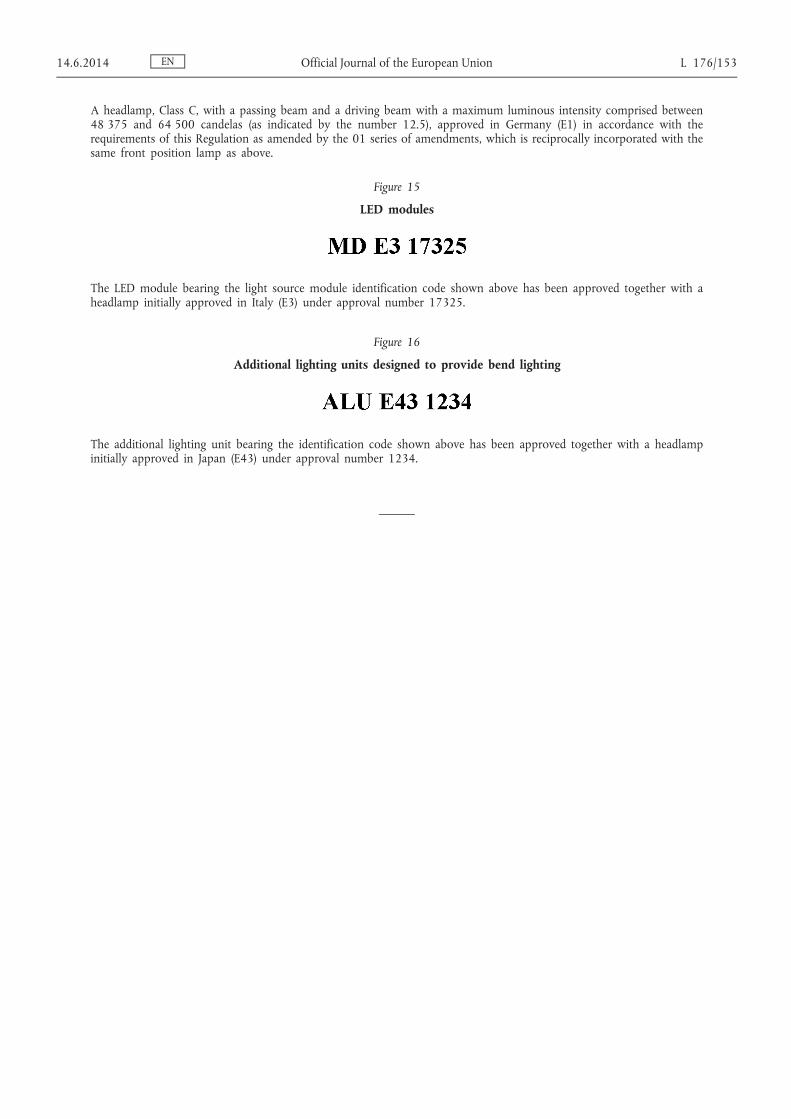
A headlamp Class C with a passing beam and a driving beam with a maximum luminous intensity comprised between 48 375 and 64 500 candelas (as indicated by the number 125) approved in Germany (E1) in accordance with the requirements of this Regulation as amended by the 01 series of amendments which is reciprocally incorporated with the same front position lamp as above
Figure 15
LED modules
The LED module bearing the light source module identification code shown above has been approved together with a headlamp initially approved in Italy (E3) under approval number 17325
Figure 16
Additional lighting units designed to provide bend lighting
The additional lighting unit bearing the identification code shown above has been approved together with a headlamp initially approved in Japan (E43) under approval number 1234
EN 1462014 Official Journal of the European Union L 176153
ANNEX 3
SPHERICAL COORDINATE MEASURING SYSTEM AND TEST POINT LOCATIONS
Figure A
Spherical Coordinate Measuring System
The angular co-ordinates are specified in degrees on a sphere with a vertical polar axis according to CIE publication No 70-1987 lsquoThe measurement of absolute luminous intensity distributionsrsquo ie corresponding to a goniometer with a horizontal (lsquoelevationrsquo) axis fixed to the ground and a second moveable (lsquorotationrsquo) axis perpendicular to the fixed horizontal axis
EN L 176154 Official Journal of the European Union 1462014
Figure B
Passing beam test points and zones for Class A headlamp(s)
H-H horizontal plane V-V vertical plane passing through focus of headlamp
Figure C
Passing beam test points and zones for Class B headlamp(s)
H-H horizontal plane V-V vertical plane passing through focus of headlamp
EN 1462014 Official Journal of the European Union L 176155
Figure D
Passing beam mdash position of test points and zones for Classes C D and E headlamp(s)
Figure E
Primary driving beam mdash position of test points
EN L 176156 Official Journal of the European Union 1462014
Figure F
Secondary driving beam mdash position of test points
EN 1462014 Official Journal of the European Union L 176157
ANNEX 4
TESTS FOR STABILITY OF PHOTOMETRIC PERFORMANCE OF HEADLAMPS IN OPERATION mdash TESTS ON COMPLETE CLASSES B C D AND E HEADLAMPS
Once the photometric values have been measured according to the prescriptions of this Regulation in the point for Imax for driving beam and in points 050 U15 L and 050 U15 R 50 R 50 L for Class B passing beam and in points 086 D-35 R 086 D-35 L 050 U-15 L and 050 U-15 R for Classes C D and E passing beam a complete headlamp sample shall be tested for stability of photometric performance in operation lsquoComplete headlamprsquo shall be understood to mean the complete lamp itself including those surrounding body parts filament lamps gas discharge light sources or LED module(s) which could influence its thermal dissipation
The tests shall be carried out
(a) In a dry and still atmosphere at an ambient temperature of 23 degC plusmn 5 degC the test sample being mounted on a base representing the correct installation on the vehicle
(b) In case of replaceable light sources using mass production filament light sources which have been aged for at least one hour or mass production gas-discharge light sources which have been aged for at least 15 hours or mass production LED modules which have been aged for at least 48 hours and cooled down to ambient temperature before starting the tests as specified in this Regulation The LED modules supplied by the applicant shall be used
The measuring equipment shall be equivalent to that used during headlamp type approval tests
The test sample shall be operated without being dismounted from or readjusted in relation to its test fixture The light source used shall be a light source of the category specified for that headlamp
1 TEST FOR STABILITY OF PHOTOMETRIC PERFORMANCE
11 Clean headlamp
The headlamp shall be operated for 12 hours as described in paragraph 111 and checked as prescribed in paragraph 112
111 Test procedure ( 1 )
The headlamp shall be operated for a period according to the specified time so that
1111 (a) In the case where only one lighting function (driving or passing beam or front fog lamp) is to be approved the corresponding light source is lit for the prescribed time ( 2 )
(b) In the case of a headlamp with a passing beam and one or more driving beams or in case of a headlamp with a passing beam and a front fog lamp
(i) The headlamp shall be subjected to the following cycle until the time specified is reached
(a) 15 minutes passing-beam lit
(b) 5 minutes all functions lit
EN L 176158 Official Journal of the European Union 1462014
( 1 ) For the test schedule see Annex 8 to this Regulation ( 2 ) When the tested headlamp includes signalling lamps the latter shall be lit for the duration of the test In the case of a direction
indicator lamp it shall be lit in flashing mode with an onoff time of approximately one to one
(ii) If the applicant declares that the headlamp is to be used with only the passing beam lit or only the driving beam(s) lit ( 3 ) at a time the test shall be carried out in accordance with this condition activating ( 2 ) successively the passing beam half of the time and the driving beam(s) (simultaneously) for half of the time specified in paragraph 11 above
(c) In the case of a headlamp with a front fog lamp and one or more driving beams
(i) The headlamp shall be subjected to the following cycle until the time specified is reached
(a) 15 minutes front fog lamp lit
(b) 5 minutes all functions lit
(ii) If the applicant declares that the headlamp is to be used with only the front fog lamp lit or only the driving beam(s) lit ( 3 ) at a time the test shall be carried out in accordance with this condition activating ( 2 ) successively the front fog lamp half of the time and the driving beam(s) (simultaneously) for half the time specified in paragraph 11 above
(d) In the case of headlamp with a passing beam one or more driving beams and a front fog lamp
(i) The headlamp shall be subjected to the following cycle until the time specified is reached
(a) 15 minutes passing-beam lit
(b) 5 minutes all functions lit
(ii) If the applicant declares that the headlamp is to be used with only the passing beam lit or only the driving beam(s) ( 3 ) lit at a time the test shall be carried out in accordance with this condition activating ( 2 ) successively the passing beam half of the time and the driving beam(s) for half the time specified in paragraph 11 above while the front fog lamp is subjected to a cycle of 15 minutes off and 5 minutes lit for half of the time and during the operation of the driving beam
(iii) If the applicant declares that the headlamp is to be used with only the passing beam lit or only the front fog lamp ( 3 ) lit at a time the test shall be carried out in accordance with this condition activating ( 2 ) successively the passing beam half of the time and the front fog lamp for half of the time specified in paragraph 11 above while the driving beam(s) is(are) subjected to a cycle of 15 minutes off and 5 minutes lit for half of the time and during the operation of the passing beam
(iv) If the applicant declares that the headlamp is to be used with only the passing beam lit or only the driving beam(s) ( 3 ) lit or only the front fog lamp ( 3 ) lit at a time the test shall be carried out in accordance with this condition activating ( 2 ) successively the passing beam one third of the time the driving beam(s) one third of the time and the front fog lamp for one third of the time specified in paragraph 11 above
(e) In the case of a headlamp having additional light source(s) used to produce bend lighting except for additional lighting unit(s) it (they) shall be switched on for one minute and switched off for nine minutes during the activation of the principal passing beam
EN 1462014 Official Journal of the European Union L 176159
( 3 ) Should two or more lamp light source be simultaneously lit when headlamp flashing is used this shall not be considered as being normal use of the light source simultaneously
If the headlamp has several additional light sources used to produce bend lighting the test shall be carried out with the combination of light source(s) that represents the most severe operating condition
1112 Test voltage
The voltage shall be applied to the terminals of the test sample as follows
(a) In case of replaceable filament light source(s) operated directly under vehicle voltage system conditions the test shall be performed at 63 V 132 V or 280 V as applicable except if the applicant specifies that the test sample may be used at a different voltage In this case the test shall be carried out with the filament light source operated at the highest voltage that can be used
(b) In case of replaceable gas discharge light source(s) The test voltage for the electronic light source control- gear or the light source in case the ballast is integrated with the light source is 132 plusmn 01 V for 12 V vehicle voltage systems or otherwise specified in the application for approval
(c) In the case of non-replaceable light sources operated directly under vehicle voltage system conditions all measurements on lighting units equipped with non-replaceable light sources (filament light sources andor others) shall be made at 63 V 132 V or 280 V or at other voltages according to the vehicle voltage system as specified by the applicant respectively
(d) In the case of light sources replaceable or non-replaceable being operated independently from vehicle supply voltage and fully controlled by the system or in the case of light sources supplied by a supply and operating device the test voltages as specified above shall be applied to the input terminals of that device The test laboratory may require from the manufacturer the supply and operating device or a special power supply needed to supply the light source(s)
(e) LED module(s) shall be measured at 675 V 132 V or 280 V respectively if not otherwise specified within this Regulation LED module(s) operated by an electronic light source control gear shall be measured as specified by the applicant
(f) Where signalling lamps are grouped combined or reciprocally incorporated into the test sample and operating at voltages other than the nominal rated voltages of 6 V 12 V or 24 V respectively the voltage shall be adjusted as declared by the manufacturer for the correct photometric functioning of that lamp
112 Test results
1121 Visual inspection
Once the headlamp has been stabilized to the ambient temperature the headlamp lens and the external lens if any shall be cleaned with a clean damp cotton cloth It shall then be inspected visually no distortion deformation cracking or change in colour of either the headlamp lens or the external lens if any shall be noticeable
1122 Photometric test
To comply with the requirements of this Regulation the photometric values shall be verified in the following points
For Class B headlamp
Passing beam 50 R mdash 50 L mdash 050 U15 L and 050 U15 R
Driving beam Point of I max
EN L 176160 Official Journal of the European Union 1462014
For Classes C D and E headlamp
Passing beam 086 D35 R mdash 086 D35 L mdash 050 U15 L and 15 R
Driving beam Point of I max
Another aiming may be carried out to allow for any deformation of the headlamp base due to heat (the change of the position of the lsquocut-offrsquo line is covered in paragraph 2 of this Annex)
Except for points 050 U15 L and 050 U15 R a 10 per cent discrepancy between the photometric characteristics and the values measured prior to the test is permissible including the tolerances of the photoshymetric procedure The value measured at points 050 U15 L and 050 U15 R shall not exceed the photoshymetric value measured prior to the test by more than 255 cd
12 Dirty headlamp
After being tested as specified in paragraph 11 above the headlamp shall be operated for one hour as described in paragraph 111 after being prepared as prescribed in paragraph 121 and checked as prescribed in paragraph 112
121 Preparations of the headlamp
1211 Test mixture
12111 For headlamp with the outside lens in glass
The mixture of water and a polluting agent to be applied to the headlamp shall be composed of
(a) 9 parts by weight of silica sand with a particle size of 0-100 μm
(b) 1 part by weight of vegetal carbon dust (beechwood) with a particle size of 0-100 μm
(c) 02 parts by weight of NaCMC ( 4 ) and
(d) An appropriate quantity of distilled water with a conductivity of le 1 mSm
The mixture must not be more than 14 days old
12112 For headlamp with outside lens in plastic material
The mixture of water and polluting agent to be applied to the headlamp shall be composed of
(a) 9 parts by weight of silica sand with a particle size of 0-100 μm
(b) 1 part by weight of vegetal carbon dust (beechwood) with a particle size of 0-100 μm
(c) 02 part by weight of NaCMC ( 4 )
(d) 13 parts by weight of distilled water with a conductivity of le 1 mSm and
EN 1462014 Official Journal of the European Union L 176161
( 4 ) NaCMC represents the sodium salt of carboxymethylcellulose customarily referred to as CMC The NaCMC used in the dirt mixture shall have a degree of substitution (DS) of 06-07 and a viscosity of 02-03 Pa s for a 2 per cent solution at 20 degC
(e) 2 plusmn 1 parts by weight of surface-actant ( 5 )
The mixture must not be more than 14 days old
1212 Application of the test mixture to the headlamp
The test mixture shall be uniformly applied to the entire light-emitting surface of the headlamp and then left to dry
This procedure shall be repeated until the illumination value has dropped to 15-20 per cent of the values measured for each of the following points under the conditions described in this Annex
For Class B headlamp
Passing beamdriving beam and driving beam only Point of E max
Passing beam only B 50 and 50 V
For Classes C D and E headlamp
Passing beamdriving beam and driving beam only Point of E max
Passing beam only 050 U15 L and 15 R and 086 DV
2 TEST FOR CHANGE IN VERTICAL POSITION OF THE lsquoCUT-OFFrsquo LINE UNDER THE INFLUENCE OF HEAT
This test consists of verifying that the vertical drift of the lsquocut-offrsquo line under the influence of heat does not exceed a specified value for an operating headlamp producing a passing beam
The headlamp tested in accordance with paragraph 1 shall be subjected to the test described in paragraph 21 without being removed from or readjusted in relation to its test fixture
21 Test
The test shall be carried out in a dry and still atmosphere at an ambient temperature of 23 degC plusmn 5 degC
Using a mass production filament lamp(s) which has been aged for at least one hour or a mass production gas-discharge light source which has been aged for at least 15 hours or the LED module(s) as submitted with the headlamps which has (have) been aged for at least 48 hours the headlamp shall be operated on passing beam without being dismounted from or readjusted in relation to its test fixture (For the purpose of this test the voltage shall be adjusted as specified in paragraph 1112) The position of the lsquocut-offrsquo line in its horizontal part (between the vertical lines passing through point 50 L and 50 R for Class B headlamp 35 L and 35 R for Classes C D and E headlamp) shall be verified 3 minutes (r 3 ) and 60 minutes (r 60 ) respectively after operation
The measurement of the variation in the lsquocut-offrsquo line position as described above shall be carried out by any method giving acceptable accuracy and reproducible results
22 Test results
221 The result in milliradians (mrad) shall be considered as acceptable for a headlamp producing a passing beam only when the absolute value Δr I frac14 jr 3 Auml r 60 j recorded on the headlamp is not more than 10 mrad (Δr I le 10 mrad)
EN L 176162 Official Journal of the European Union 1462014
( 5 ) The tolerance on quantity is due to the necessity of obtaining a dirt that correctly spreads out on all the plastic lens
222 However if this value is more than 10 mrad but not more than 15 mrad (10 mrad lt Δr I le 15 mrad) a second headlamp shall be tested as described in paragraph 21 after being subjected three consecutive times to the cycle as described below in order to stabilize the position of mechanical parts of the headlamp on a base representative of the correct installation on the vehicle
Operation of the passing beam for one hour (the voltage shall be adjusted as specified in paragraph 1112)
Period of rest for one hour
The headlamp type shall be considered as acceptable if the mean value of the absolute values Δr I measured on the first sample and Δr II measured on the second sample is not more than 10 mrad
EN 1462014 Official Journal of the European Union L 176163
ANNEX 5
MINIMUM REQUIREMENTS FOR CONFORMITY OF PRODUCTION CONTROL PROCEDURES
1 GENERAL
11 The conformity requirements shall be considered satisfied from a mechanical and a geometrical standpoint if the differences do not exceed inevitable manufacturing deviations within the requirements of this Regulation This condition also applies to colour
12 For Classes A B C and D headlamps
121 With respect to photometric performances the conformity of mass-produced headlamps shall not be contested if when testing photometric performances of any headlamp chosen at random and equipped with standard filament lamp(s) andor LED module(s) as present in the lamp
122 For Class A headlamps no measured value deviates unfavourably by more than 20 per cent from the value prescribed in this Regulation
123 For Classes B C and D headlamps
1231 No measured value deviates unfavourably by more than 20 per cent from the value prescribed in this Regulation For values in zone 1 for Classes B C and D headlamps the maximum unfavourable deviation may be respectively
255 cd equivalent 20 per cent
380 cd equivalent 30 per cent
1232 And if for the driving beam a tolerance of + 20 per cent for maximum values and ndash 20 per cent for minimum values is observed for the photometric values at any measuring point specified in paragraphs 6331 or 6332 of this Regulation
124 If in the case of a lamp equipped with a replaceable filament light source according to Regulation No 37 the results of the tests described above do not meet the requirements tests shall be repeated using another standard filament lamp(s)
125 If the results of the tests described above do not meet the requirements the alignment of the headlamp may be changed provided that the axis of the beam is not displaced laterally by more than 05 degree to the right or left and not by more than 02 degree up or down
13 For Class E headlamps
131 For Class E headlamps measured at 132 V plusmn 01 V or as otherwise specified and equipped with
(a) A removable standard gas-discharge light source according to Regulation No 99 In this case the luminous flux of this gas-discharge light source may differ from the reference luminous flux specified in Regulation No 99 and the illuminances shall be corrected accordingly
or
(b) A serial production gas-discharge light source and a serial ballast In this case the luminous flux of this light source may deviate from the nominal luminous flux due to light source and ballast tolerances as specified in Regulation No 99 and accordingly the measured illuminances may be corrected by 20 per cent in the favourable direction
EN L 176164 Official Journal of the European Union 1462014
or
(c) LED modules as present in the lamp
The conformity of mass-produced headlamps chosen at random and equipped with a gas discharge lamp andor LED module(s) present in the headlamp with respect to photometric performance shall not be contested provided that
132 No measured value deviates unfavourably by more than 20 per cent from the value prescribed in this Regulation For values in zone 1 the maximum unfavourable deviation may be respectively
255 cd equivalent 20 per cent
380 cd equivalent 30 per cent
133 And if for the driving beam a tolerance of + 20 per cent for maximum values and ndash 20 per cent for minimum values is observed for the photometric values at any measuring point specified in paragraphs 6331 or 6332 of this Regulation
134 If the results of the tests described above do not meet the requirements the alignment of the headlamp may be changed provided that the axis of the beam is not displaced laterally by more than 05 degree to the right or left and not by more than 02 degree up or down
135 If the results of the tests described above do not meet the requirements tests on the headlamp shall be repeated using another standard gas-discharge light source andor ballast or LED module and electronic light source control gear whichever is applicable according to paragraph 131 above
14 With respect to the verification of the change in vertical position of the lsquocut-offrsquo line under the influence of heat the following procedure shall be applied (Classes B C D and E headlamps only)
One of the sampled headlamps shall be tested according to the procedure described in paragraph 21 of Annex 4 after being subjected three consecutive times to the cycle described in paragraph 222 of Annex 4
The headlamp shall be considered as acceptable if Δr does not exceed 15 mrad
If this value exceeds 15 mrad but is not more than 20 mrad a second sample shall be subjected to the test after which the mean of the absolute values recorded on both samples shall not exceed 15 mrad
15 Headlamps with apparent defects are disregarded
16 If however for a series of samples vertical adjustment cannot be performed repeatedly to the required position within the allowed tolerances the quality of lsquocut-offrsquo shall be tested on one of the headlamps from the series of samples according to the procedure described in Annex 9 paragraphs 2 and 4
2 MINIMUM REQUIREMENTS FOR VERIFICATION OF CONFORMITY BY THE MANUFACTURER
For each type of headlamp the holder of the approval mark shall carry out at least the following tests at appropriate intervals The tests shall be carried out in accordance with the provision of this Regulation
If any sampling shows non-conformity with regard to the type of test concerned further samples shall be taken and tested The manufacturer shall take steps to ensure the conformity of the production concerned
21 Nature of tests
Tests of conformity in this Regulation shall cover the photometric characteristics and for Classes B C D and E headlamps the verification of the change in vertical position of the lsquocut-offrsquo line under influence of heat
EN 1462014 Official Journal of the European Union L 176165
22 Methods used in tests
221 Tests shall generally be carried out in accordance with the methods set out in this Regulation
222 In any test of conformity carried out by the manufacturer equivalent methods may be used with the consent of the competent authority responsible for approval tests The manufacturer is responsible for proving that the applied methods are equivalent to those laid down in this Regulation
223 The application of paragraphs 221 and 222 requires regular calibration of test apparatus and its correlation with measurement made by a competent authority
224 In all cases the reference methods shall be those of this Regulation particular for the purpose of administrative verification and sampling
23 Nature of sampling
Samples of headlamps shall be selected at random from the production of a uniform batch A uniform batch means a set of headlamps of the same type defined according to the production methods of the manufacturer
The assessment shall in general cover series production from individual factories However a manufacturer may group together records concerning the same type from several factories provided these operate under the same quality system and quality management
24 Measured and recorded photometric characteristics
The sampled headlamps shall be subjected to photometric measurements at the points provided for in the Regulation the reading being limited at the points
241 For Class A headlamps HV LH RH 125 L and 125 R
242 For Class B headlamps I max HV ( 1 ) in the case of the driving beam and to the points HV 086 D35 R 086 D35 L in the case of the passing beam
243 For Classes C D and E headlamps I max HV ( 1 ) in the case of the driving beam and to the points HV 086 D35 R 086 D35 L in the case of the passing beam
25 Criteria governing acceptability
The manufacturer is responsible for carrying out a statistical study of the test results and for defining in agreement with the competent authority criteria governing acceptability of his products in order to meet the specification laid down for verification of conformity of products in paragraph 91 of this Regulation
The criteria governing acceptability shall be such that with a confidence level of 95 per cent the minimum probability of passing a spot check in accordance with Annex 7 (first sampling) would be 095
EN L 176166 Official Journal of the European Union 1462014
( 1 ) When the driving beam is reciprocally incorporated with the passing beam HV in the case of the driving beam shall be the same measuring point as in the case of the passing beam
ANNEX 6
REQUIREMENTS FOR LAMPS INCORPORATING LENSES OF PLASTIC MATERIAL mdash TESTING OF LENS OR MATERIAL SAMPLES AND OF COMPLETE LAMPS
1 GENERAL SPECIFICATIONS
11 The samples supplied pursuant to paragraph 224 of this Regulation shall satisfy the specifications indicated in paragraphs 21 to 25 below
12 The two samples of complete lamps supplied pursuant to paragraph 223 of this Regulation and incorporating lenses of plastic material shall with regard to the lens material satisfy the specifications indicated in paragraph 26 below
13 The samples of lenses of plastic material or samples of material shall be subjected with the reflector to which they are intended to be fitted (where applicable) to approval tests in the chronological order indicated in table A reproduced in Appendix 1 to this Annex
14 However if the lamp manufacturer can prove that the product has already passed the tests prescribed in paragraphs 21 to 25 below or the equivalent tests pursuant to another Regulation those tests need not be repeated only the tests prescribed in Appendix 1 table B shall be mandatory
2 TESTS
21 Resistance to temperature changes
211 Tests
Three new samples (lenses) shall be subjected to five cycles of temperature and humidity (RH = relative humidity) change in accordance with the following programme
(a) 3 hours at 40 degC plusmn 2 degC and 85-95 per cent RH
(b) 1 hour at 23 degC plusmn 5 degC and 60-75 per cent RH
(c) 15 hours at ndash 30 degC plusmn 2 degC
(d) 1 hour at 23 degC plusmn 5 degC and 60-75 per cent RH
(e) 3 hours at 80 degC plusmn 2 degC
(f) 1 hour at 23 degC plusmn 5 degC and 60-75 per cent RH
Before this test the samples shall be kept at 23 degC plusmn 5 degC and 60-75 per cent RH for at least four hours
Note The periods of one hour at 23 degC plusmn 5 degC shall include the periods of transition from one temperature to another which are needed in order to avoid thermal shock effects
212 Photometric measurements
2121 Method
Photometric measurements shall be carried out on the samples before and after the test
These measurements shall be made using a standard (eacutetalon) lamp a standard gas-discharge light source or (an) LED module(s) as present in the headlamp at the following points
EN 1462014 Official Journal of the European Union L 176167
B 50 50 L and 50 R for Class B headlamp 086 D35 R 086 D35 L 050 U15 L and 15 R for Classes C D and E headlamp for the passing beam or a passingdriving lamp
I max for the driving beam of a driving lamp or a passingdriving lamp
2122 Results
The variation between the photometric values measured on each sample before and after the test shall not exceed 10 per cent including the tolerances of the photometric procedure
22 Resistance to atmospheric and chemical agents
221 Resistance to atmospheric agents
Three new samples (lenses or samples of material) shall be exposed to radiation from a source having a spectral energy distribution similar to that of a black body at a temperature between 5 500 K and 6 000 K Appropriate filters shall be placed between the source and the samples so as to reduce as far as possible radiations with wave lengths smaller than 295 nm and greater than 2 500 nm The samples shall be exposed to an energetic illumination of 1 200 Wm 2 plusmn 200 Wm 2 for a period such that the luminous energy that they receive is equal to 4 500 MJm 2 plusmn 200 MJm 2 Within the enclosure the temperature measured on the black panel placed on a level with the samples shall be 50 degC plusmn 5 degC In order to ensure a regular exposure the samples shall revolve around the source of radiation at a speed between 1 and 5 min ndash1
The samples shall be sprayed with distilled water of conductivity lower than 1 mSm at a temperature of 23 degC plusmn 5 degC in accordance with the following cycle
Spraying 5 minutes drying 25 minutes
222 Resistance to chemical agents
After the test described in paragraph 221 above and the measurement described in paragraph 2231 below have been carried out the outer face of the said three samples shall be treated as described in paragraph 2222 with the mixture defined in paragraph 2221 below
2221 Test mixture
The test mixture shall be composed of 615 per cent n-heptane 125 per cent toluene 75 per cent ethyl tetrachloride 125 per cent trichloroethylene and 6 per cent xylene (volume per cent)
2222 Application of the test mixture
Soak a piece of cotton cloth (as specified in ISO 105) until saturation with the mixture defined in paragraph 2221 above and within 10 seconds apply it for 10 minutes to the outer face of the sample at a pressure of 50 Ncm 2 corresponding to an effort of 100 N applied on a test surface of 14 times 14 mm
During this 10-minute period the cloth pad shall be soaked again with the mixture so that the composition of the liquid applied is continuously identical with that of the test mixture prescribed
During the period of application it is permissible to compensate the pressure applied to the sample in order to prevent it from causing cracks
2223 Cleaning
At the end of the application of the test mixture the samples shall be dried in the open air and then washed with the solution described in paragraph 23 (resistance to detergents) 23 degC plusmn 5 degC
Afterwards the samples shall be carefully rinsed with distilled water containing not more than 02 per cent impurities at 23 degC plusmn 5 degC and then wiped off with a soft cloth
EN L 176168 Official Journal of the European Union 1462014
223 Results
2231 After the test of resistance to atmospheric agents the outer face of the samples shall be free from cracks
scratches chipping and deformation and the mean variation in transmission Δt frac14 T 2 Auml T 3
T 2 measured on the
three samples according to the procedure described in Appendix 2 to this Annex shall not exceed 0020 (Δt m lt 0020)
2232 After the test of resistance to chemical agents the samples shall not bear any traces of chemical staining likely to
cause a variation of flux diffusion whose mean variation Δt frac14 T 5 Auml T 4
T 2 measured on the three samples
according to the procedure described in Appendix 2 to this Annex shall not exceed 0020 (Δdm le 0020)
23 Resistance to detergents and hydrocarbons
231 Resistance to detergents
The outer face of three samples (lenses or samples of material) shall be heated to 50 degC plusmn 5 degC and then immersed for five minutes in a mixture maintained at 23 degC plusmn 5 degC and composed of 99 parts distilled water containing not more than 002 per cent impurities and one part alkylaryl sulphonate
At the end of the test the samples shall be dried at 50 degC plusmn 5 degC
The surface of the samples shall be cleaned with a moist cloth
232 Resistance to hydrocarbons
The outer face of these three samples shall then be lightly rubbed for one minute with a cotton cloth soaked in a mixture composed of 70 per cent n-heptane and 30 per cent toluene (volume per cent) and shall then be dried in the open air
233 Results
After the above two tests have been performed successively the mean value of the variation in transmission
Δt frac14 T 2 Auml T 3
T 2 measured on the three samples according to the procedure described in Appendix 2 to this
Annex shall not exceed 0010 (Δt m le 0010)
24 Resistance to mechanical deterioration
241 Mechanical deterioration method
The outer face of the three new samples (lenses) shall be subjected to the uniform mechanical deterioration test by the method described in Appendix 3 to this Annex
242 Results
After this test the variations
in transmission Δt frac14 T 2 Auml T 3
T 2
and in diffusion Δt frac14 T 5 Auml T 4
T 2
shall be measured according to the procedure described in Appendix 2 in the area specified in paragraph 22411 of this Regulation The mean value of the three samples shall be such that
Δt m le 0100
Δd m le 0050
EN 1462014 Official Journal of the European Union L 176169
25 Test of adherence of coatings if any
251 Preparation of the sample
A surface of 20 mm times 20 mm in area of the coating of a lens shall be cut with a razor blade or a needle into a grid of squares approximately 2 mm times 2 mm The pressure on the blade or needle shall be sufficient to cut at least the coating
252 Description of the test
Use an adhesive tape with a force adhesion of 2 N(cm of width) plusmn 20 per cent measured under the standardized conditions specified in Appendix 4 to this Annex This adhesive tape which shall be at least 25 mm wide shall be pressed for at least five minutes to the surface prepared as prescribed in paragraph 251
Then the end of the adhesive tape shall be loaded in such a way that the force of adhesion to the surface considered is balanced by a force perpendicular to that surface At this stage the tape shall be torn off at a constant speed of 15 ms plusmn 02 ms
253 Results
There shall be no appreciable impairment of the gridded area Impairments at the intersections between squares or at the edges of the cuts shall be permitted provided that the impaired area does not exceed 15 per cent of the gridded surface
26 Tests of the complete headlamp incorporating a lens of plastic material
261 Resistance to mechanical deterioration of the lens surface
2611 Tests
The lens of lamp sample No 1 shall be subjected to the test described in paragraph 241 above
2612 Results
After the test the results of photometric measurements carried out on the headlamp in accordance with this Regulation shall not exceed
(a) By more than 30 per cent the maximum values prescribed at point HV and shall not be more than 10 per cent below the minimum values prescribed at point 50 L and 50 R for Class B headlamp 086 D35 R 086 D35 L for Class C D and E headlamp
(b) By more than 10 per cent below the minimum values prescribed for HV in the case of a headlamp producing driving beam only
262 Test of adherence of coatings if any
The lens of lamp sample No 2 shall be subjected to the test described in paragraph 25 above
27 Resistance to light source radiations
The following test shall be done
Flat samples of each light transmitting plastic component of the headlamp are exposed to the light of the LED module(s) or the gas-discharge light source The parameters such as angles and distances of these samples shall be the same as in the headlamp These samples shall have the same colour and surface treatment if any as the parts of the headlamp
After 1 500 hours of continuous operation the colorimetric specifications of the transmitted light must be met and the surfaces of the samples shall be free of cracks scratches scalings or deformation
EN L 176170 Official Journal of the European Union 1462014
3 VERIFICATION OF THE CONFORMITY OF PRODUCTION
31 With regard to the materials used for the manufacture of lenses the lamps of a series shall be recognized as complying with this Regulation if
311 After the test for resistance to chemical agents and the test for resistance to detergents and hydrocarbons the outer face of the samples exhibits no cracks chipping or deformation visible to the naked eye (see paragraphs 222 231 and 232)
312 After the test described in paragraph 2611 the photometric values at the points of measurement considered in paragraph 2612 are within the limits prescribed for conformity of production by this Regulation
32 If the test results fail to satisfy the requirements the tests shall be repeated on another sample of headlamps selected at random
EN 1462014 Official Journal of the European Union L 176171
Appendix 1
CHRONOLOGICAL ORDER OF APPROVAL TESTS
A Tests on plastic materials (lenses or samples of material supplied pursuant to paragraph 224 of this Regulation)
Samples Tests
Lenses or samples of material Lenses
1 2 3 4 5 6 7 8 9 10 11 12 13 14
11 Limited photometry
(para 212) x x x
111 Temperature change
(para 211) x x x
112 Limited photometry
(para 212) x x x
121 Transmission measurement x x x x x x x x x
122 Diffusion measurement x x x x x x
13 Atmospheric agents
(para 221) x x x
131 Transmission measurement x x x
14 Chemical agents
(para 222) x x x
141 Diffusion measurement x x x
15 Detergents
(para 231) x x x
16 Hydrocarbons
(para 232) x x x
161 Transmission measurement x x x
17 Deterioration
(para 241) x x x
171 Transmission measurement x x x
172 Diffusion measurement x x x
18 Adherence
(para 25) x
19 Resistance to light source radiations
(para 27) x
EN L 176172 Official Journal of the European Union 1462014
B Tests on complete headlamps (supplied pursuant to paragraph 223 of this Regulation)
Tests
Complete headlamp
Sample No
1 2
21 Deterioration
(para 2611) x
22 Photometry
(para 2612) x
23 Adherence
(para 262) x
EN 1462014 Official Journal of the European Union L 176173
Appendix 2
METHOD OF MEASUREMENT OF THE DIFFUSION AND TRANSMISSION OF LIGHT
1 Equipment (see figure)
The beam of a collimator K with a half divergence β2 = 174 times 10 4 rd is limited by a diaphragm Dτ with an opening of 6 mm against which the sample stand is placed
A convergent achromatic lens L 2 corrected for spherical aberrations links the diaphragm Dτ with the receiver R the diameter of the lens L 2 shall be such that it does not diaphragm the light diffused by the sample in a cone with a half top angle of β2 = 14deg
An annular diaphragm D D with angles αdeg2 = 1deg and αmax2 = 12deg is placed in an image focal plane of the lens L 2
The non-transparent central part of the diaphragm is necessary in order to eliminate the light arriving directly from the light source It shall be possible to remove the central part of the diaphragm from the light beam in such a manner that it returns exactly to its original position
The distance L 2 Dτ and the focal length F 2 ( 1 ) of the lens L 2 shall be so chosen that the image of Dτ completely covers the receiver R
When the initial incident flux is referred to 1 000 units the absolute precision of each reading shall be better than 1 unit
2 Measurements
The following readings shall be taken
Reading With sample With central part of DD Quantity represented
T 1 no no Incident flux in initial reading
T 2 yes (before test) no Flux transmitted by the new material in a field of 24deg
T 3 yes (after test) no Flux transmitted by the tested material in a field of 24deg
T 4 yes (before test) yes Flux diffused by the new material
T 5 yes (after test) yes Flux diffused by the tested material
EN L 176174 Official Journal of the European Union 1462014
( 1 ) For L 2 it is recommended to use a focal distance of about 80 mm
EN 1462014 Official Journal of the European Union L 176175
Appendix 3
SPRAY TESTING METHOD
1 Test equipment
11 Spray gun
The spray gun used shall be equipped with a nozzle 13 mm in diameter allowing a liquid flow rate of 024 plusmn 002 lminute at an operating pressure of 60 bars ndash 0+ 05 bar
Under these operation conditions the fan pattern obtained shall be 170 mm plusmn 50 mm in diameter on the surface exposed to deterioration at a distance of 380 mm plusmn 10 mm from the nozzle
12 Test mixture
The test mixture shall be composed of
Silica sand of hardness 7 on the Mohr scale with a grain size between 0 and 02 mm and an almost normal distribution with an angular factor of 18 to 2
Water of hardness not exceeding 205 gm 3 for a mixture comprising 25 g of sand per litre of water
2 Test
The outer surface of the lamp lenses shall be subjected once or more than once to the action of the sand jet produced as described above The jet shall be sprayed almost perpendicular to the surface to be tested
The deterioration shall be checked by means of one or more samples of glass placed as a reference near the lenses to be tested The mixture shall be sprayed until the variation in the diffusion of light on the sample or samples measured by the method described in Appendix 2 is such that
Δd frac14 T 5 Auml T 4
T 2 frac14 00250 Euml 00025
Several reference samples may be used to check that the whole surface to be tested has deteriorated homogeneously
EN L 176176 Official Journal of the European Union 1462014
Appendix 4
ADHESIVE TAPE ADHERENCE TEST
1 PURPOSE
This method allows to determine under standard conditions the linear force of adhesion of an adhesive tape to a glass plate
2 PRINCIPLE
Measurement of the force necessary to unstick an adhesive tape from a glass plate at an angle of 90deg
3 SPECIFIED ATMOSPHERIC CONDITIONS
The ambient conditions shall be at 23 degC plusmn 5 degC and 65 plusmn 15 per cent RH
4 TEST PIECES
Before the test the sample roll of adhesive tape shall be conditioned for 24 hours in the specified atmosphere (see paragraph 3 above)
Five test pieces each 400 mm long shall be tested from each roll These test pieces shall be taken from the roll after the first three turns were discarded
5 PROCEDURE
The test shall be under the ambient conditions specified in paragraph 3
Take the five test pieces while unrolling the tape radially at a speed of approximately 300 mms then apply them within 15 seconds in the following manner
Apply the tape to the glass plate progressively with a slight length-wise rubbing movement of the finger without excessive pressure in such a manner as to leave no air bubble between the tape and the glass plate
Leave the assembly in the specified atmospheric conditions for 10 minutes
Unstick about 25 mm of the test piece from the plate in a plane perpendicular to the axis of the test piece Fix the plate and fold back the free end of the tape at 90deg Apply force in such a manner that the separation line between the tape and the plate is perpendicular to this force and perpendicular to the plate
Pull to unstick at a speed of 300 mms plusmn 30 mms and record the force required
6 RESULTS
The five values obtained shall be arranged in order and the median value taken as a result of the measurement This value shall be expressed in Newtons per centimetre of width of the tape
EN 1462014 Official Journal of the European Union L 176177
ANNEX 7
MINIMUM REQUIREMENTS FOR SAMPLING BY AN INSPECTOR
1 GENERAL
11 The conformity requirements shall be considered satisfied from a mechanical and a geometrical standpoint in accordance with the requirements of this Regulation if any if the differences do not exceed inevitable manushyfacturing deviations This condition also applies to colour
12 For Classes A B C and D headlamps
121 With respect to photometric performances the conformity of mass-produced headlamps shall not be contested if when testing photometric performances of any headlamp chosen at random and equipped with standard filament lamp(s) andor LED module(s) as present in the headlamp
122 Class A headlamps no measured value deviates unfavourably by more than 20 per cent from the value prescribed in this Regulation
123 Classes B C and D headlamps
1231 No measured value deviates unfavourably by more than 20 per cent from the value prescribed in this Regulation For values in zone 1 for Classes B C and D headlamps the maximum unfavourable deviation may be respectively
255 cd equivalent 20 per cent
380 cd equivalent 30 per cent
1232 And if for the driving beam a tolerance of + 20 per cent for maximum values and ndash 20 per cent for minimum values is observed for the photometric values at any measuring point specified in paragraph 6331 or 6332 of this Regulation
124 If the results of the tests described above do not meet the requirements tests shall be repeated using other standard filament lamp(s)
125 If the results of the tests described above do not meet the requirements the alignment of the headlamp may be changed provided that the axis of the beam is not displaced laterally by more than 05 degree to the right or left and not by more than 02 degree up or down
13 For Class E headlamps
131 For Class E headlamps measured at 132 V plusmn 01 V or as otherwise specified and equipped with
(a) A removable standard gas-discharge light source according to Regulation No 99 In this case the luminous flux of this gas-discharge light source may differ from the reference luminous flux specified in Regulation No 99 and the illuminances shall be corrected accordingly
or
(b) A serial production gas-discharge light source and a serial ballast In this case the luminous flux of this light source may deviate from the nominal luminous flux due to light source and ballast tolerances as specified in Regulation No 99 and accordingly the measured illuminances may be corrected by 20 per cent in the favourable direction
or
(c) LED modules as present in the lamp
EN L 176178 Official Journal of the European Union 1462014
The conformity of mass-produced headlamps chosen at random and equipped with a Gas Discharge lamp andor LED module(s) present in the headlamp with respect to photometric performance shall not be contested provided that
132 No measured value deviates unfavourably by more than 20 per cent from the value prescribed in this Regulation For values in zone 1 the maximum unfavourable deviation may be respectively
255 cd equivalent 20 per cent
380 cd equivalent 30 per cent
133 And if for the driving beam a tolerance of + 20 per cent for maximum values and ndash 20 per cent for minimum values is observed for the photometric values at any measuring point specified in paragraph 6331 or 6332 of this Regulation
134 If the results of the tests described above do not meet the requirements the alignment of the headlamp may be changed provided that the axis of the beam is not displaced laterally by more than 05 degrees to the right or left and not by more than 02 degrees up or down
135 If the results of the tests described above do not meet the requirements tests on the headlamp shall be repeated using another standard gas-discharge light source a gas-discharge light source andor ballast or (an) LED module(s) and electronic light source control gear(s) whatever is applicable according to paragraph 131 above
14 Headlamps with apparent defects are disregarded
15 If however for a series of samples vertical adjustment cannot be performed repeatedly to the required position within the allowed tolerances the quality of lsquocut-offrsquo shall be tested on one of the headlamps from the series of samples according to the procedure described in Annex 9 paragraphs 2 and 4
2 FIRST SAMPLING
In the first sampling four headlamps are selected at random The first sample of two is marked A the second sample of two is marked B
21 The conformity is not contested
211 Following the sampling procedure shown in Figure 1 of this Annex the conformity of mass-produced headlamps shall not be contested if the deviations of the measured values of the headlamps in the unfavourable directions are
2111 Sample A
A1 one headlamp 0 per cent
one headlamp not more than 20 per cent
A2 both headlamps more than 0 per cent
but not more than 20 per cent
Go to sample B
2112 Sample B
B1 both headlamps 0 per cent
EN 1462014 Official Journal of the European Union L 176179
22 The conformity is contested
221 Following the sampling procedure shown in Figure 1 of this Annex the conformity of mass-produced headlamps shall be contested and the manufacturer requested to make his production meet the requirements (alignment) if the deviations of the measured values of the headlamps are
2211 Sample A
A3 one headlamp not more than 20 per cent
one headlamp more than 20 per cent
but not more than 30 per cent
2212 Sample B
B2 in the case of A2
one headlamp more than 0 per cent
but not more than 20 per cent
one headlamp not more than 20 per cent
B3 in the case of A2
one headlamp 0 per cent
one headlamp more than 20 per cent
but not more than 30 per cent
23 Approval withdrawn
Conformity shall be contested and paragraph 11 applied if following the sampling procedure shown in Figure 1 of this Annex the deviations of the measured values of the headlamps are
231 Sample A
A4 one headlamp not more than 20 per cent
one headlamp more than 30 per cent
A5 both headlamps more than 20 per cent
232 Sample B
B4 in the case of A2
one headlamp more than 0 per cent
but not more than 20 per cent
one headlamp more than 20 per cent
B5 in the case of A2
both headlamps more than 20 per cent
B6 in the case of A2
one headlamp 0 per cent
one headlamp more than 30 per cent
EN L 176180 Official Journal of the European Union 1462014
3 REPEATED SAMPLING
In the case of A3 B2 B3 a repeated sampling third sample C of two headlamps selected from stock manushyfactured after alignment is necessary within two monthsrsquo time after the notification
31 The conformity is not contested
311 Following the sampling procedure shown in Figure 1 of this Annex the conformity of mass-produced headlamps shall not be contested if the deviations of the measured values of the headlamps are
3111 Sample C
C1 one headlamp 0 per cent
one headlamp not more than 20 per cent
C2 both headlamps more than 0 per cent
but not more than 20 per cent
Go to sample D
3112 Sample D
D1 in the case of C2
both headlamps 0 per cent
32 The conformity is contested
321 Following the sampling procedure shown in Figure 1 of this Annex the conformity of mass-produced headlamps shall be contested and the manufacturer requested to make his production meet the requirements (alignment) if the deviations of the measured values of the headlamps are
3211 Sample D
D2 in the case of C2
one headlamp more than 0 per cent
but not more than 20 per cent
one headlamp not more than 20 per cent
33 Approval withdrawn
Conformity shall be contested and paragraph 11 applied if following the sampling procedure shown in Figure 1 of this Annex the deviations of the measured values of the headlamps are
331 Sample C
C3 one headlamp not more than 20 per cent
one headlamp more than 20 per cent
C4 both headlamps more than 20 per cent
332 Sample D
D3 in the case of C2
one headlamp 0 or more than 0 per cent
one headlamp more than 20 per cent
EN 1462014 Official Journal of the European Union L 176181
Figure 1
EN L 176182 Official Journal of the European Union 1462014
ANNEX 8
OVERVIEW OF OPERATIONAL PERIODS CONCERNING TEST FOR STABILITY OF PHOTOMETRIC PERFORMANCE
Abbreviations P passing beam lamp
D driving beam lamp (D 1 + D 2 means two driving beams)
F front fog lamp
means a cycle of 15 minutes off and 5 minutes lit
means a cycle of 9 minutes off and 1 minutes lit
All following grouped headlamps and front fog lamps together with the added class B marking symbols are given as examples and are not exhaustive
1 P or D or F (C-BS or R-BS or B) Additional light source(s) used to produce bend lighting
2 P+D (CR-BS) or P+D 1 +D 2 (CR-BS R-BS) Additional light source(s) used to produce bend lighting
3 P+D (CR-BS) or P+D 1 +D 2 (CR-BS R-BS) Additional light source(s) used to produce bend lighting
4 P+F (C-BS B) Additional light source(s) used to produce bend lighting
5 P+F (C-BS B) or C-BSB Additional light source(s) used to produce bend lighting
6 D+F (R-BS B) or D 1 +D 2 +F (R-BS R-BS B) Additional light source(s) used to produce bend lighting
7 D+F (R-BS B) or D 1 +D 2 +F (R-BS R-BS B) Additional light source(s) used to produce bend lighting
EN 1462014 Official Journal of the European Union L 176183
8 P+D+F (CR-BS B) or P+D 1 +D 2 +F (CR-BS R-BS B)
Additional light source(s) used to produce bend lighting
9 P+D+F (CR-BS B) or P+D 1 +D 2 +F (CR-BS R-BS B)
Additional light source(s) used to produce bend lighting
10 P+D+F (CR-BS B) or P+D 1 +D 2 +F (CR-BS R-BS B)
Additional light source(s) used to produce bend lighting
11 P+D+F (CR-BS B) or P+D 1 +D 2 +F (CR-BS R-BSB)
Additional light source(s) used to produce bend lighting
EN L 176184 Official Journal of the European Union 1462014
ANNEX 9
DEFINITION AND SHARPNESS OF THE lsquoCUT-OFFrsquo LINE FOR SYMMETRICAL PASSING BEAM HEADLAMPS AND AIMING PROCEDURE BY MEANS OF THIS lsquoCUT-OFFrsquo LINE
1 GENERAL
11 The luminous intensity distribution of the symmetrical passing-beam headlamps shall incorporate a lsquocut-offrsquo line which enables the symmetrical passing-beam headlamp to be adjusted correctly for the photometric measurements and for the aiming on the vehicle The characteristics of the lsquocut-offrsquo line shall comply with the requirements set out in paragraphs 2 to 4 below
2 SHAPE OF THE lsquoCUT-OFFrsquo LINE
21 For visual adjustment of the symmetrical passing-beam headlamp the lsquocut-offrsquo line shall provide a horizontal line for vertical adjustment of the symmetrical passing-beam headlamp extending to either side of the V-V line (see Figure 1) as specified in paragraph 621 of this Regulation
Figure 1
Shape and position of the lsquocut-offrsquo line
3 ADJUSTMENT OF THE SYMMETRICAL PASSING-BEAM HEADLAMP
31 Horizontal adjustment the beam with the lsquocut-offrsquo line shall be so positioned that the projected beam pattern appears approximately symmetrical to the V-V line
32 Vertical adjustment after horizontal adjustment of the symmetrical passing-beam headlamp according to paragraph 31 above the vertical adjustment shall be performed in such a way that the beam with its lsquocut-offrsquo line is moved upwards from the lower position until the lsquocut-offrsquo line is situated at nominal vertical position For nominal vertical adjustment the lsquocut-offrsquo line is positioned on the V-V line at 1 per cent below the h-h line
If the horizontal part is not straight but slightly curved or inclined the lsquocut-offrsquo line shall not exceed the vertical range formed by two horizontal lines which are situated from 3deg left to 3deg right of the V-V line at 02deg for Class B and 03deg for Classes A C D and E headlamps above and below the nominal position of the lsquocut-offrsquo (see Figure 1)
33 When the vertical adjustments of three different individuals differs by more than 02deg for Class B and 03deg for Classes A C D and E head lamps the horizontal part of the lsquocut-offrsquo line is assumed not to provide sufficient linearity or sharpness for performing visual adjustment In this case the quality of lsquocut-offrsquo shall be tested instrumentally for compliance with requirements as follows
4 MEASUREMENT OF THE QUALITY OF lsquoCUT-OFFrsquo
41 Measurements shall be performed by vertically scanning through the horizontal part of the lsquocut-offrsquo line in angular steps not exceeding 005deg
(a) At either a measurement distance of 10 m and a detector with a diameter of approximately 10 mm
EN 1462014 Official Journal of the European Union L 176185
(b) Or at a measurement distance of 25 m and a detector with a diameter of approximately 30 mm
The measurement of the lsquocut-offrsquo quality shall be considered acceptable if the requirements of the paragraph 412 of this Annex shall comply with at least one measurement at 10 m or 25 m
The measuring distance at which the test was determined shall be noted down in paragraph 9 Annex 1 lsquoCommunication formrsquo of this Regulation
The scanning is performed from its lower position upwards through the lsquocut-offrsquo line along the vertical lines at - 3deg to - 15deg and + 15deg to + 3deg from the V-V line When so measured the quality of the lsquocut-offrsquo line shall meet the following requirements
411 Not more than one lsquocut-offrsquo line shall be visible ( 1 )
412 Sharpness of lsquocut-offrsquo if scanned vertically through the horizontal part of the lsquocut-offrsquo line along the plusmn 25 lines the maximum value measured for
G frac14 ethlog E V Auml log E ethV thorn 01degTHORN THORN
is called the sharpness factor G of the lsquocut-offrsquo line The value of G shall not be less than 013 for Class B and 008 for Classes A C D and E
413 Linearity the part of the lsquocut-offrsquo line which serves for vertical adjustment shall be horizontal from 3degL to 3degR of the V-V line This requirement is deemed to be met if the vertical positions of the inflection points according to paragraph 32 above at 3deg left and right of the V-V line do not differ by more than 02deg for Class B and 03deg for Classes A C D and E headlamps from the nominal position at the V-V line
5 INSTRUMENTAL VERTICAL ADJUSTMENT
If the lsquocut-offrsquo line complies with the above quality requirements the vertical beam adjustment can be performed instrumentally For this purpose the inflection point where d 2 (log E)dv 2 = 0 is positioned on the V-V line in its nominal position below the h-h-line The movement for measuring and adjusting the lsquocut-offrsquo line shall be upwards from below the nominal position
EN L 176186 Official Journal of the European Union 1462014
( 1 ) This paragraph will be amended if an objective test method is available
ANNEX 10
CENTRE OF REFERENCE
Diameter = a
a = 2 mm min
This optional mark of the centre of reference shall be positioned on the lens at its intersection with the reference axis of the passing beam and also on the lenses of the driving beams when they are neither grouped nor combined nor reciprocally incorporated with a passing beam
The above drawing represents the mark of the centre of reference as projected on a plane substantially tangent to the lens about the centre of the circle The lines constituting this mark may either be solid or dotted
EN 1462014 Official Journal of the European Union L 176187
ANNEX 11
VOLTAGE MARKINGS
This marking must be placed on the main body of each headlamp containing only gas discharge light sources and ballast and on each external part of the ballast
This marking must be placed on the main body of each headlamp containing at least one gas discharge light source and ballast
The ballast(s) is(are) designed for a Volts network system
The ballast(s) is(are) designed for a Volts network system
None of the filament lamps which the headlamp contains is designed for a 24 Volts network system
EN L 176188 Official Journal of the European Union 1462014
ANNEX 12
REQUIREMENTS FOR LED MODULES AND HEADLAMPS INCLUDING LED MODULES
1 GENERAL SPECIFICATIONS
11 Each LED module sample submitted shall conform to the relevant specifications of this Regulation when tested with the supplied electronic light source control-gear(s) if any
12 LED module(s) shall be so designed as to be and to remain in good working order when in normal use They shall moreover exhibit no fault in design or manufacture A LED module shall be considered to have failed if any one of its LEDs has failed
13 LED module(s) shall be tamperproof
14 The design of removable LED module(s) shall be such that
141 When the LED module is removed and replaced by another module provided by the applicant and bearing the same light source module identification code the photometric specifications of the headlamp shall be met
142 LED modules with different light source module identification codes within the same lamp housing shall not be interchangeable
2 MANUFACTURE
21 The LED(s) on the LED module shall be equipped with suitable fixation elements
22 The fixation elements shall be strong and firmly secured to the LED(s) and the LED module
3 TEST CONDITIONS
31 Application
311 All samples shall be tested as specified in paragraph 4 below
312 The kind of light sources on a LED MODULE shall be light-emitting diodes (LED) as defined in Regulation No 48 paragraph 271 in particular with regard to the element of visible radiation Other kinds of light sources are not permitted
32 Operating conditions
321 LED module operating conditions
All samples shall be tested under the conditions as specified in paragraph 613 of this Regulation If not specified differently in this Annex LED modules shall be tested inside the headlamp as submitted by the manufacturer
322 Ambient temperature
For the measurement of electrical and photometric characteristics the headlamp shall be operated in dry and still atmosphere at an ambient temperature of 23 degC plusmn 5 degC
33 Ageing
Upon the request of the applicant the LED module shall be operated for 48 h and cooled down to ambient temperature before starting the tests as specified in this Regulation
EN 1462014 Official Journal of the European Union L 176189
4 SPECIFIC SPECIFICATIONS AND TESTS
41 Colour rendering
411 Red content
In addition to measurements as described in paragraph 7 of this Regulation the minimum red content of the light of a LED module or headlamp incorporating LED module(s) tested at 50 V shall be such that
k red frac14 eth 780 nm
λfrac14610 nm
E e ethλTHORN VethλTHORN dλ eth 780 nm
λfrac14380 nm
E e ethλTHORN VethλTHORN dλ
ETH 005
where
E e (λ) (unit W) is the spectral distribution of the irradiance
V(λ) (unit 1) is the spectral luminous efficiency
(λ) (unit nm) is the wavelength
This value shall be calculated using intervals of one nanometre
42 UV-radiation
The UV-radiation of a low-UV-type LED module shall be such that
k UV frac14 eth 400 nm
λfrac14250 nm
E e ethλTHORN SethλTHORN dλ
k m eth 780 nm
λfrac14380 nm
E e ethλTHORN VethλTHORN dλ
Iuml 10 ndash5 W=lm
where
S(λ)(unit 1) is the spectral weighting function
k m = 683 lmW is the maximum value of the luminous efficacy of radiation
(For definitions of the other symbols see paragraph 411 above)
This value shall be calculated using intervals of one nanometre The UV-radiation shall be weighted according to the values as indicated in the Table UV below
Table UV
Values according to lsquoIRPAINIRC Guidelines on limits of exposure to ultraviolet radiationrsquo Wavelengths (in nanometres) chosen are representative other values should be interpolated
λ S(λ)
250 0430
255 0520
260 0650
265 0810
270 1000
275 0960
280 0880
285 0770
290 0640
295 0540
300 0300
λ S(λ)
305 0060
310 0015
315 0003
320 0001
325 000050
330 000041
335 000034
340 000028
345 000024
350 000020
λ S(λ)
355 000016
360 000013
365 000011
370 000009
375 0000077
380 0000064
385 0000530
390 0000044
395 0000036
400 0000030
EN L 176190 Official Journal of the European Union 1462014
43 Temperature stability
431 Illuminance
4311 A photometric measurement of the headlamp shall be made after 1 minute of operation for the specific function at the test point specified below For these measurements the aim can be approximate but must be maintained for before and after ratio measurements
Test points to be measured
Principal passing beam 50 V
(For the measurement of bend lighting the test point shall be specified by the manufacturer)
Driving beam H mdash V
4312 The lamp shall continue operation until photometric stability has occurred The moment at which the photometry is stable is defined as the point in time at which the variation of the photometric value is less than 3 per cent within any 15 minute period After stability has occurred aim for complete photometry shall be performed in accordance with requirements of specific device Photometer the lamp at all test points required for the specific device
4313 Calculate the ratio between the photometric test point value determined in paragraph 4311 and the point value determined in paragraph 4312
4314 Once stability of photometry has been achieved apply the ratio calculated above to each of the remainder of the test points to create a new photometric table that describes the complete photometry based on one minute of operation
4315 The luminous intensity values measured after one minute and after photometric stability has occurred shall comply with the minimum and maximum requirements
432 Colour
The colour of the light emitted measured after one minute and measured after photometric stability has been obtained as described in paragraph 4312 of this Annex shall both be within the required colour boundaries
5 The measurement of the objective luminous flux of LED module(s) producing the principal passing beam shall be carried out as follows
51 The LED module(s) shall be in the configuration as described in the technical specification as defined in paragraph 222 of this Regulation Optical elements (secondary optics) shall be removed by the Technical Service at the request of the applicant by the use of tools This procedure and the conditions during the measurements as described below shall be described in the test report
52 Three LED modules of each type shall be submitted by the applicant with the light source control gear if applicable and sufficient instructions
Suitable thermal management (eg heat sink) may be provided to simulate similar thermal conditions as in the corresponding headlamp application
Before the test each LED module shall be aged at least for 48 hours under the same conditions as in the corresponding headlamp application
EN 1462014 Official Journal of the European Union L 176191
In the case of use of an integrating sphere the sphere shall have a minimum diameter of one meter and at least ten times the maximum dimension of the LED module whichever is the largest The flux measurements can also be performed by integration using a goniophotometer The prescriptions in the CIE mdash Publication 84 mdash 1989 regarding the room temperature positioning etc shall be taken into consideration
The LED module shall be burned in for approximately one hour in the closed sphere or goniophotometer
The flux shall be measured after stability has occurred as explained in paragraph 4312 of this Annex
The average of the measurements of the three samples of each type of LED module shall be deemed to be its objective luminous flux
EN L 176192 Official Journal of the European Union 1462014
- Regulation No 113 of the Economic Commission for Europe of the United Nations (UNECE) mdash Uniform provisions concerning the approval of motor vehicle headlamps emitting a symmetrical passing beam or a driving beam or both and equipped with filament gas-discharge light sources or LED modules
-

SCOPE ( 1 ) ( 2 )
This Regulation applies to headlamps for vehicles of categories L and T ( 3 )
1 DEFINITIONS
For the purpose of this Regulation
11 lsquoLensrsquo means the outermost component of the headlamp (unit) which transmits light through the illuminating surface
12 lsquoCoatingrsquo means any product or products applied in one or more layers to the outer face of a lens
13 lsquoHeadlamps of different typesrsquo mean headlamps which differ in such essential respects as
131 The trade name or mark
132 The characteristics of the optical system
133 The inclusion or elimination of components capable of altering the optical effects by reflection refraction absorption andor deformation during operation
134 The kind of beam produced (passing beam driving beam or both)
135 The category of filament lamp(s) the gas-discharge light source or the light source module specific identifishycation code(s)
14 lsquoHeadlamps of different ldquoClassesrdquo (A or B or C or D or E)rsquo mean headlamps identified by particular photometric provisions
15 lsquoColour of the light emitted from the devicersquo The definitions of the colour of the light emitted given in Regulation No 48 and its series of amendments in force at the time of application for type approval shall apply to this Regulation
16 However in the case of a system consisting of two headlamps a device intended for the installation on the left side of the vehicle and the corresponding device intended for the installation on the right side of the vehicle shall be considered to be of the same type
17 References made in this Regulation to standard (eacutetalon) filament lamp(s) and to Regulation No 37 shall refer to Regulation No 37 and its series of amendments in force at the time of application for type approval
18 References made in this Regulation to standard (eacutetalon) gas discharge light sources(s) and to Regulation No 99 shall refer to Regulation No 99 and its series of amendments in force at the time of application for type approval
EN 1462014 Official Journal of the European Union L 176129
( 1 ) Application of headlamps is given in the relevant Regulations on the installation of lighting and light-signalling devices ( 2 ) Nothing in this Regulation shall prevent a Party to the Agreement applying this Regulation from prohibiting the combination of a
headlamp incorporating a lens of plastic material approved under this Regulation with a mechanical headlamp-cleaning device (with wipers)
( 3 ) As defined in the Consolidated Resolution on the Construction of Vehicles (RE3) document TRANSWP2978Rev2 para 2
19 lsquoAdditional lighting unitrsquo means the part of a headlamp system that provides the bend lighting It is indeshypendent from the device that provides the principal passing beam may consist of optical mechanical and electrical components and it may be grouped andor reciprocally incorporated with other lighting or light- signalling devices
110 Other relevant definitions given in Regulations No 48 53 and 74 and their series of amendments in force at the time of application for type approval shall apply to this Regulation
2 APPLICATION FOR APPROVAL OF A HEADLAMP ( 1 )
21 The application for approval shall be submitted by the owner of the trade name or mark or by his duly accredited representative It shall specify
211 Whether the headlamp is intended to provide both a passing beam and a driving beam or only one of these beams
212 Whether it concerns a Class A or B or C or D or E headlamp
213 The category of the filament lamp(s) used as listed in Regulation No 37 and its series of amendments in force at the time of application for type approval if any
214 The category of gas-discharge light source as listed in Regulation No 99 if any
215 For LED modules the light source module specific identification code(s) if any
216 For additional lighting unit(s) the additional lighting unit identification code(s) if any
22 Every application for approval shall be accompanied by
221 Drawings in triplicate in sufficient detail to permit identification of the type and representing a frontal view of the headlamp with details of lens ribbing if any and the cross-section the drawings shall indicate the space reserved for the approval mark and if applicable
(a) In the case of LED module(s) the drawings shall indicate also the space(s) reserved for the specific identification code(s) of the module(s)
(b) In the case of additional lighting unit(s) the space(s) reserved for the specific identification code(s) on the additional lighting unit(s) and the headlamp(s) producing the principal passing beam
(c) In the case of additional lighting unit(s) the geometrical conditions of installation of the device(s) that meet the requirements of paragraph 628
222 A brief technical description including
2221 For gas discharge lamps the make and type of the ballast(s) in the case that the ballast(s) is (are) not integrated with the light source(s)
EN L 176130 Official Journal of the European Union 1462014
( 1 ) For gas-discharge light sources see Regulation No 99
2222 In the case of LED module(s)
(a) A brief technical specification of the LED module(s)
(b) A drawing with dimensions and the basic electrical and photometric values and the objective luminous flux and for each LED module a statement whether it is replaceable or not
(c) In case of electronic light source control gear information on the electrical interface necessary for approval testing
2223 In the case of a headlamp designed to provide bend lighting the minimum bank angle(s) to satisfy the requirement of paragraph 6281
223 Two samples of the type of headlamp In the case of a system consisting of two headlamps one sample intended for the installation on the left side of the vehicle and one sample intended for the installation on the right side of the vehicle
224 For Class B or C or D or E headlamps only for the test of plastic material of which the lenses are made
2241 For Class B or C or D or E fourteen lenses
22411 For Class B C D or E ten of these lenses may be replaced by ten samples of material at least 60 times 80 mm in size having a flat or convex outer surface and a substantially flat area (radius of curvature not less than 300 mm) in the middle measuring at least 15 times 15 mm
22412 Every such lens or sample of material shall be produced by the method to be used in mass production
2242 A reflector to which the lenses can be fitted in accordance with the manufacturerrsquos instructions
225 For headlamps equipped with light sources according to Regulation No 99 or equipped with LED modules only for testing the UV-resistance of light transmitting components made of plastic material against UV radiation of the light sources inside the headlamp
2251 One sample each of the relevant material as being used in the headlamp or one headlamp sample containing these Each material sample shall have the same appearance and surface treatment if any as intended for use in the headlamp to be approved
2252 The UV-resistance testing of internal materials to light source radiation is not necessary
22521 If low-UV-type gas-discharge light sources are being applied as specified in Regulation No 99 or
22522 If only low-UV-type LED modules as specified in Annex 12 to this Regulation are being applied or
22523 If provisions are taken to shield the relevant headlamp components from UV radiation eg by glass filters
226 One ballast or electronic light source control gear as applicable
23 The materials making up the lenses and coatings if any shall be accompanied by the test report of the characteristics of these materials and coatings if they have already been tested
EN 1462014 Official Journal of the European Union L 176131
3 MARKINGS
31 Headlamps submitted for approval shall bear the trade name or mark of the applicant
32 They shall comprise on the lens and on the main body ( 1 ) spaces of sufficient size for the approval mark and the additional symbols referred to in paragraph 4 these spaces shall be indicated on the drawings referred to in paragraph 221 above
33 On the back of the headlamp the indication of the category of filament lamp(s) or gas-discharge light source used
34 Class E headlamps may bear on their light-emitting surface a centre of reference as shown in Annex 10
35 Class E headlamps shall bear the voltage markings as shown in Annex 11
36 In the case of lamps with LED module(s) the lamp shall bear the marking of the rated voltage and rated wattage and the light source module specific identification code
37 LED module(s) submitted along with the approval of the lamp shall bear
371 The trade name or mark of the applicant This marking shall be clearly legible and indelible
372 The specific identification code of the module This marking shall be clearly legible and indelible
This specific identification code shall comprise the starting letters lsquoMDrsquo for lsquoMODULErsquo followed by the approval marking without the circle as prescribed in paragraph 421 below and in the case several non-identical light source modules are used followed by additional symbols or characters This specific identification code shall be shown in the drawings mentioned in paragraph 221 above The approval marking does not have to be the same as the one on the lamp in which the module is used but both markings shall be from the same applicant
373 If the LED module(s) are non-replaceable the markings for LED module(s) are not required
38 If an electronic light source control gear which is not part of a LED module is used to operate a LED module(s) it shall be marked with its specific identification code(s) the rated input voltage and wattage
39 In the case of additional lighting unit(s) the headlamps producing the principal passing beam shall bear specific identification code of the additional lighting unit(s) mentioned in paragraph 3102 below
310 Additional lighting unit(s) shall bear the following markings
3101 The trade name or mark of the applicant This marking shall be clearly legible and indelible
3102 In the case of filament light source the category(s) of filament lamp(s) andor
EN L 176132 Official Journal of the European Union 1462014
( 1 ) If the lens cannot be detached from the main body of the headlamp a unique marking as specified in paragraph 425 shall be sufficient
In the case of LED module(s) the rated voltage and rated wattage and the specific identification code(s) of the LED module(s)
3103 The specific identification code(s) of the additional lighting unit(s) This marking shall be clearly legible and indelible
This specific identification code shall be comprised of starting letters lsquoALUrsquo for lsquoAdditional Lighting Unitrsquo followed by approval marking without the circle as prescribed in paragraph 421 below (ex ALU E43 1234) and in the case where several non-identical additional lighting units are used additional symbols or characters shall follow (ex ALU E43 1234-A ALU E43 1234-B) This specific identification code shall be shown in the drawings mentioned in paragraph 221 above The approval marking does not have to be the same as the one on the lamp in which the additional lighting unit(s) is used but both markings shall be from the same applicant
4 APPROVAL
41 General
411 If all the samples of a type of headlamp submitted pursuant to paragraph 2 above satisfy the provisions of this Regulation approval shall be granted
412 Where grouped combined or reciprocally incorporated lamps satisfy the requirements of more than one Regulation a single international approval mark may be affixed provided that each of the grouped combined or reciprocally incorporated lamps satisfies the provisions applicable to it
413 An approval number shall be assigned to each type approved Its first two digits shall indicate the series of amendments incorporating the most recent major technical amendments made to the Regulation at the time of issue of the approval The same Contracting Party may not assign the same number to another type of headlamp covered by this Regulation
414 Notice of approval or of extension or refusal or withdrawal of approval or production definitively disconshytinued of a type of headlamp pursuant to this Regulation shall be communicated to the Parties to the 1958 Agreement applying this Regulation by means of a form conforming to the model in Annex 1 to this Regulation
415 In addition to the mark prescribed in paragraph 31 an approval mark as described in paragraphs 42 and 43 below shall be affixed in the spaces referred to in paragraph 32 above to every headlamp conforming to a type approved under this Regulation
42 Composition of the approval mark
The approval mark shall consist of
421 An international approval marking comprising
4211 A circle surrounding the letter lsquoErsquo followed by the distinguishing number of the country which has granted approval ( 1 )
4212 The approval number prescribed in paragraph 413 above
422 The following additional symbol
4221 A horizontal arrow with a head on each end pointing to the left and to the right
EN 1462014 Official Journal of the European Union L 176133
( 1 ) The distinguishing numbers of the Contracting Parties to the 1958 Agreement are reproduced in Annex 3 to Consolidated Resolution on the Construction of Vehicles (RE3) document TRANSWP2978Rev2Amend1
4222 On headlamps meeting the requirements of this Regulation in respect of the passing beam only the letters lsquoC- ASrsquo for Class A headlamps or lsquoC-BSrsquo for Class B headlamps or lsquoWC-CSrsquo for Class C headlamp or lsquoWC-DSrsquo for Class D headlamp or lsquoWC-ESrsquo for Class E headlamps
4223 On headlamps meeting the requirements of this Regulation in respect of the driving beam only lsquoR-BSrsquo for Class B headlamps or lsquoWR-CSrsquo for Class C headlamp or lsquoWR-DSrsquo for Class D headlamp or lsquoWR-ESrsquo for Class E headlamps
4224 On headlamps meeting the requirements of this Regulation in respect of both the passing beam and the driving beam the letters lsquoCR-BSrsquo for Class B headlamps or lsquoWCR-CSrsquo for Class C headlamp or lsquoWCR-DSrsquo for Class D headlamp or lsquoWCR-ESrsquo for Class E headlamps
4225 On headlamps incorporating a lens of plastic material the group of letters lsquoPLrsquo to be affixed near the symbols prescribed in paragraphs 421 and 422 above
4226 On headlamps other than Class A meeting the requirements of this Regulation in respect of the driving beam an indication of the maximum luminous intensity expressed by a reference mark as defined in paragraph 634 below placed near the circle surrounding the letter lsquoErsquo
423 In every case the relevant operating mode used during the test procedure according to paragraph 1111 of Annex 4 and the permitted voltage(s) according to paragraph 1112 of Annex 4 shall be stipulated on the approval forms and on the communication forms transmitted to the countries which are Contracting Parties to the Agreement and which apply this Regulation
In the corresponding cases the device shall be marked as follows
4231 on headlamps meeting the requirements of this Regulation which are so designed that the filament lamp gas- discharge light source or LED module(s) producing the passing beam shall not be lit simultaneously with that of any other lighting function with which it may be reciprocally incorporated an oblique stroke () shall be placed behind the passing lamp symbol in the approval mark
424 The two digits of the approval number which indicate the series of amendments incorporating the most recent major technical amendments made to the Regulation at the time of issue of the approval and the arrow defined in paragraph 4221 may be marked close to the above additional symbols
425 The marks and symbols referred to in paragraphs 421 to 423 above shall be clearly legible and be indelible They may be placed on an inner or outer part (transparent or not) of the headlamp which cannot be separated from the transparent part of the headlamp emitting the light In any case they shall be visible when the headlamp is fitted on the vehicle or when a movable part is opened
43 Arrangement of the approval mark
431 Annex 2 Figures 1 to 15 to this Regulation gives examples of arrangements of the approval mark with the above-mentioned additional symbols
432 Grouped combined or reciprocally incorporated lamps
4321 Where grouped combined or reciprocally incorporated lamps have been found to comply with the requirements of several Regulations a single international approval mark may be affixed consisting of a circle surrounding the letter lsquoErsquo followed by the distinguishing number of the country which has granted the approval and an approval number This approval mark may be located anywhere on the grouped combined or reciprocally incorporated lamps provided that
EN L 176134 Official Journal of the European Union 1462014
43211 It is visible as specified in paragraph 425
43212 No part of the grouped combined or reciprocally incorporated lamps that transmits light can be removed without at the same time removing the approval mark
4322 The identification symbol for each lamp appropriate to each Regulation under which approval has been granted together with the corresponding series of amendments incorporating the most recent major technical amendments to the Regulation at the time of issue of the approval and if necessary the required arrow shall be marked
43221 Either on the appropriate light-emitting surface
43222 Or in a group in such a way that each of the grouped combined or reciprocally incorporated lamps may be clearly identified
4323 The size of the components of a single approval mark shall not be less than the minimum size required for the smallest of the individual marks by the Regulation under which approval has been granted
4324 An approval number shall be assigned to each type approved The same Contracting Party may not assign the same number to another type of grouped combined or reciprocally incorporated lamps covered by this Regulation
4325 Annex 2 Figure 13 to this Regulation gives examples of arrangements of approval marks for grouped combined or reciprocally incorporated lamps with all the above mentioned additional symbols
433 Lamps the lens of which are used for different types of headlamps and which may be reciprocally incorshyporated or grouped with other lamps
The provisions laid down in paragraph 432 above are applicable
4331 In addition where the same lens is used the latter may bear the different approval marks relating to the different types of headlamps or units of lamps provided that the main body of the headlamp even if it cannot be separated from the lens also comprises the space described in paragraph 32 above and bears the approval marks of the actual functions If different types of headlamps comprise the same main body the latter may bear the different approval marks
4332 Annex 2 Figure 14 to this Regulation gives examples of arrangements of approval marks relating to the above case
5 GENERAL SPECIFICATIONS ( 1 )
51 Each sample shall conform to the specifications set forth in paragraphs 6 to 8 below
52 Headlamps shall be so made as to retain their prescribed photometric characteristics and to remain in good working order when in normal use in spite of the vibrations to which they may be subjected
EN 1462014 Official Journal of the European Union L 176135
( 1 ) Technical requirements for filament lamp see Regulation No 37 Technical requirements for gas-discharge light sources see Regushylation No 99
521 Headlamps shall be fitted with a device enabling them to be so adjusted on the vehicles as to comply with the rules applicable to them Such a device may or may not provide horizontal adjustment provided that the headlamps are so designed that they can maintain a proper horizontal aiming even after the vertical aiming adjustment Such a device need not be fitted on units in which the reflector and the diffusing lens cannot be separated provided the use of such units is confined to vehicles on which the headlamp setting can be adjusted by other means
Where a headlamp providing a passing beam and a headlamp providing a driving beam each equipped with its own filament lamp(s) gas-discharge light source or LED module(s) are assembled to form a composite unit the adjusting device shall enable each optical system individually to be duly adjusted
522 However these provisions shall not apply to headlamp assemblies whose reflectors are indivisible For this type of assembly the requirements of paragraph 63 of this Regulation apply
53 Class A B C or D
531 Headlamps shall be equipped with filament lamp(s) approved according to Regulation No 37 andor for headlamps of class C or D with (an) LED module(s)
In the case of the use of additional light source(s) andor additional lighting unit(s) to provide bend lighting only categories of filament lamps covered by Regulation No 37 provided that no restriction on the use for bending light is made in Regulation No 37 and its series of amendments in force at the time of application for type approval andor LED modules(s) shall be used
532 It is possible to use two filament light sources for the principal passing beam and several filament light sources for the driving beam
Any Regulation No 37 filament lamp may be used provided that
(a) No restriction on the use is made in Regulation No 37 and its series of amendments in force at the time of application for type approval
(b) For Class A and B its reference luminous flux at 132 V for principal dipped-beam does not exceed 900 lm
(c) For Class C and D its reference luminous flux at 132 V for principal dipped-beam does not exceed 2 000 lm
The design of the device shall be such that the filament lamp can be fixed in no other position but the correct one ( 1 )
The filament lamp holder shall conform to the characteristics given in IEC Publication 60061 The holder data sheet relevant to the category of filament lamp used applies
533 For lamps equipped with (an) LED module(s)
5331 The electronic light source control gear(s) if applicable shall be considered as being part of the headlamp they may also be part of the LED module(s)
EN L 176136 Official Journal of the European Union 1462014
( 1 ) A headlamp is regarded as satisfying the requirements of this paragraph if the filament lamp can be easily fitted into the headlamp and the positioning lugs can be correctly fitted into their slots even in darkness
5332 The headlamp and the LED module(s) themselves shall comply with the relevant requirements specified in Annex 12 to this Regulation The compliance with the requirements shall be tested
5333 The total objective luminous flux of all LED modules producing the principal passing beam shall be measured as described in paragraph 5 of Annex 12 The following minimum and maximum limits shall apply
Headlamps Class A
Headlamps Class B
Headlamps Class C
Headlamps Class D
Principal passing beam minimum
150 lumen 350 lumen 500 lumen 1 000 lumen
Principal passing beam maximum
900 lumen 1 000 lumen 2 000 lumen 2 000 lumen
5334 In the case of a replaceable LED module the removal and replacement of this LED module as described in Annex 12 paragraph 141 shall be demonstrated to the satisfaction of the Technical Service
54 Class E headlamps
541 The headlamp shall be equipped with (a) gas-discharge light source(s) approved according to Regulation No 99 andor (an) LED module(s)
In the case of the use of additional light source(s) andor additional lighting unit(s) to provide bend lighting only categories of filament lamps covered by Regulation No 37 provided that no restriction on the use for bending light is made in Regulation No 37 and its series of amendments in force at the time of application for type andor LED modules(s) shall be used
542 In the case of replaceable gas-discharge light sources the lamp holder shall conform to the dimensional characteristics as given on the data sheet of IEC Publication 60061-2 relevant to the category of gas- discharge light source used The gas-discharge light source shall fit easily into the headlamp
543 In the case of (an) LED module(s) the following requirements apply
5431 The electronic light source control gear(s) if applicable shall be considered as being part of the headlamp they may also be part of the LED module(s)
5432 The headlamp and the LED module(s) themselves shall comply with the relevant requirements specified in Annex 12 to this Regulation The compliance with the requirements shall be tested
5433 The total objective luminous flux of all LED modules producing the principal passing beam shall be measured as described in paragraph 5 of Annex 12 The following minimum limit shall apply
Headlamps Class E
Principal passing beam minimum 2 000 lumen
55 In addition Class B or C or D or E headlamps shall be complementary tested according to the requirements of Annex 4 to ensure that in use there is no excessive change in photometric performance
56 If the lens of a Class B C D or E headlamp is of plastic material tests shall be done according to the requirements of Annex 6
EN 1462014 Official Journal of the European Union L 176137
57 On headlamps designed to provide alternately a driving beam and a passing beam or headlamp systems including additional light source(s) andor additional lighting unit(s) used to produce bend lighting any mechanical electromechanical or other device incorporated in the headlamp for these purposes shall be so constructed that
571 The device is robust enough to withstand 50 000 operations under normal conditions of use In order to verify compliance with this requirement the Technical Service responsible for approval tests may
(a) Require the applicant to supply the equipment necessary to perform the test
(b) Forego the test if the headlamp presented by the applicant is accompanied by a test report issued by a Technical Service responsible for approval tests for headlamps of the same construction (assembly) confirming compliance with this requirement
572 except for additional light source(s) and additional lighting unit(s) used to produce bend lighting in the case of failure it must be possible to obtain automatically a passing beam or a state with respect to the photometric conditions which yields values not exceeding 1 200 cd in Zone 1 and at least 2 400 cd at 086 D-V by such means as eg switching off dimming aiming downwards andor functional substitution
573 except for additional light source(s) and additional lighting unit(s) used to produce bend lighting either the passing beam or the driving beam shall always be obtained without any possibility of the mechanism stopping in between the two positions
574 The user cannot with ordinary tools change the shape or position of the moving parts
58 For Class E the headlamp and ballast system shall not generate radiated or power line disturbances to cause a malfunction of other electricelectronic systems of the vehicle ( 1 )
59 The definitions in paragraphs 27113 and 27117 in Regulation No 48 allow the use of LED module which may contain holders for other light sources Notwithstanding this provision a mixture of LEDrsquo(s) and other light sources for the passing beam or each driving beam as specified by this Regulation is not allowed
510 A LED module shall be
(a) Only removable from its device with the use of tools unless it is stated in the communication sheet that the LED module is non replaceable and
(b) So designed that regardless of the use of tool(s) it is not mechanically interchangeable with any replaceable approved light source
6 ILLUMINATION
61 General provisions
611 Headlamps shall be so made that they give adequate illumination without dazzle when emitting the passing beam and good illumination when emitting a driving beam
612 The luminous intensity produced by the headlamp shall be measured at 25 m distance by means of a photoelectric cell having a useful area comprised within a square of 65 mm side The point HV is the centre-point of the coordinate system with a vertical polar axis Line H is the horizontal through HV (see Annex 3 to this Regulation)
EN L 176138 Official Journal of the European Union 1462014
( 1 ) Compliance with the requirements for electromagnetic compatibility is relevant to the individual vehicle type
613 For Class A or B or C or D
6131 Apart from (an) LED module(s) the headlamps shall be checked by means of an uncoloured standard (eacutetalon) filament lamp designed for a rated voltage of 12 V During the checking of the headlamp the voltage at the terminals of the filament lamp shall be regulated so as to obtain the reference luminous flux at 132 V as indicated at the relevant data sheet of Regulation No 37
In order to protect the standard (eacutetalon) filament lamp during the process of photometric measurement it is permissible to carry out the measurements at a luminous flux that differs from the reference luminous flux at 132 V If the test laboratory chooses to carry out measurements in such a manner the luminous intensity shall be corrected by multiplying the measured value by the individual factor F lamp of the standard (eacutetalon) filament lamp in order to verify the compliance with the photometric requirements where
F lamp = Φ reference Φ test
Φ reference is the reference luminous flux at 132 V as specified in the relevant data sheet of Regulation No 37
Φ test is the actual luminous flux used for the measurement
6132 Depending on the number of filament lamps for which the headlamp is designed it shall be considered acceptable if it meets the requirements of paragraph 6 with the same number of standard (eacutetalon) filament lamp(s) which may be submitted with the headlamp
6133 LED module(s) shall be measured at 63 V or 132 V respectively if not otherwise specified within this Regulation LED module(s) operated by an electronic light source control gear shall be measured as specified by the applicant
614 For Class E with (a) gas-discharge light source(s) according to Regulation No 99
6141 The headlamp shall be deemed satisfactory if the photometric requirements set in the present paragraph 6 are met with one light source which has been aged during at least 15 cycles in accordance with Annex 4 paragraph 4 of Regulation No 99
Where the gas-discharge light source is approved according to Regulation No 99 it shall be a standard (eacutetalon) light-source and its luminous flux may differ from the objective luminous flux specified in Regulation No 99 In this case the illuminances shall be corrected accordingly
The above correction does not apply to distributed lighting systems using a non-replaceable gas-discharge light source or to headlamps with the ballast(s) totally or partially integrated
Where the gas-discharge light source is not approved according to Regulation No 99 it shall be a production non-replaceable light source
The voltage applied to the terminals of the ballast(s) is either 132 V plusmn 01 V for 12 V systems or as otherwise specified (see Annex 11)
6142 The dimensions determining the position of the arc inside the standard gas-discharge light source are shown in the relevant data sheet of Regulation No 99
6143 Four seconds after ignition of a headlamp which has not been operated for 30 minutes or more at least 37 500 cd must be reached at point HV of a driving beam and 3 750 cd at point 2 (086 D-V) of a passing beam for headlamps incorporating driving beam and passing beam functions or 3 750 cd at point 2 (086 D- V) for headlamps having only a passing beam function The power supply shall be sufficient to secure the quick rise of the high current pulse
EN 1462014 Official Journal of the European Union L 176139
615 For Class E with (an) LED module(s)
6151 LED module(s) shall be measured at 63 V or 132 V respectively if not otherwise specified within this Regulation LED module(s) operated by an electronic light source control gear shall be measured as specified by the applicant
616 In the case of headlamp systems having additional light source(s) andor additional lighting unit(s) used to produce bend lighting the additional light source(s) shall be measured according to the paragraphs 613 614 and 615
62 Provisions concerning passing beams
621 For a correct aiming the principal passing beam shall produce a sufficiently sharp lsquocut-offrsquo to permit a satisfactory visual adjustment with its aid as indicated in paragraph 622 below The aiming shall be carried out using a flat vertical screen set up at a distance of 10 or 25 m forward of the headlamp and at right angles to the H-V The screen shall be sufficiently wide to allow examination and adjustment of the lsquocut- offrsquo of the passing beam over at least 3deg on either side of the V-V line The lsquocut-offrsquo shall be substantially horizontal and shall be as straight as possible from at least 3deg L to 3deg R In case the visual aim leads to problems or ambiguous positions the instrumental method as specified in Annex 9 paragraphs 2 and 4 shall be applied and the quality or rather the sharpness of the lsquocut-offrsquo and the linearity shall be checked on performance
622 The principal passing beam shall be aimed so that
6221 For horizontal adjustment The beam is as symmetrical as possible with reference to line V-V
6222 For vertical adjustment the horizontal part of the lsquocut-offrsquo line is adjusted to its nominal position (057 degree) below the H-H line
If however vertical adjustment cannot be performed repeatedly to the required position within the allowed tolerances the instrumental method of Annex 9 paragraphs 4 and 5 shall be applied to test compliance with the required minimum quality of the lsquocut-offrsquo line and to perform the beam vertical adjustment
623 When so aimed the headlamp must if its approval is sought solely for provision of a passing beam ( 1 ) comply with the requirements set out in paragraphs 625 and 626 below if it is intended to provide both a passing beam and a driving beam it shall comply with the requirements set out in paragraphs 625 626 and 63
624 Where a headlamp so aimed does not meet the requirements set out in paragraphs 625 626 and 63 its alignment may be changed except for headlamps that have no mechanism to adjust horizontal aim on condition that the axis of the beam is not displaced laterally by more than 05 degree to the right or left and vertically by not more than 025 degree up or down To facilitate alignment by means of the lsquocut-offrsquo the headlamp may be partially occulted in order to sharpen the lsquocut-offrsquo However the lsquocut-offrsquo should not extend beyond the line H-H
625 The passing beam shall meet the requirements as shown in the applicable table below and the applicable figure as shown in Annex 3
Notes
For Class E headlamps the voltage applied to the terminals of the ballast(s) is either 132 V plusmn 01 V for 12 V systems or as otherwise specified (see Annex 11)
EN L 176140 Official Journal of the European Union 1462014
( 1 ) Such a special lsquopassing beamrsquo headlamp may incorporate a driving beam not subject to requirements
lsquoDrsquo means under the H-H line
lsquoUrsquo means above the H-H line
lsquoRrsquo means right of the V-V line
lsquoLrsquo means left of the V-V line
6251 For Class A headlamps (Figure B in Annex 3)
Test pointlinezone Angular coordinates mdash degrees () Required luminous intensity in cd
Any point in Zone 1 0deg to 15degU 5degL to 5degR le 320 cd
Any point on line 25 L to 25 R 172degD 5degL to 5degR ge 1 100 cd
Any point on line 125 L to 125 R 343degD 5degL to 5degR ge 550 cd
() 025deg tolerance allowed independently at each test point for photometry unless indicated otherwise
6252 For Class B headlamps (Figure C in Annex 3)
Test pointlinezone Angular coordinates mdash degrees () Required luminous intensity in cd
Any point in Zone 1 0deg to 15degU 5degL to 5degR le 700 cd
Any point on line 50 L to 50 R except 50 V 086degD 25degL to 25degR ge 1 100 cd
Point 50 V 086degD 0 ge 2 200 cd
Any point on line 25 L to 25 R 172degD 5degL to 5degR ge 2 200 cd
Any point in Zone 2 086degD to 172degD 5degL to 5degR ge 1 100 cd
() 025deg tolerance allowed independently at each test point for photometry unless indicated otherwise
6253 For Class C D or E headlamp (Figure D in Annex 3)
Test point linezone Test point angular coordinates degrees ()
Required luminous intensity in cd
Minimum Maximum
Class C Class D Class E Classes C D E
1 086degD 35degR 2 000 2 000 2 500 13 750
2 086degD 0 2 450 4 900 4 900 mdash
3 086degD 35degL 2 000 2 000 2 500 13 750
4 050degU 150degL and 150degR mdash mdash mdash 900
5 200degD 15degL and 15degR 550 1 100 1 100 mdash
6 400degD 20degL and 20degR 150 300 600 mdash
EN 1462014 Official Journal of the European Union L 176141
Test point linezone Test point angular coordinates degrees ()
Required luminous intensity in cd
Minimum Maximum
Class C Class D Class E Classes C D E
7 0 0 mdash mdash mdash 1 700
Line 1 200degD 9degL to 9degR 1 350 1 350 1 900 mdash
8 () 400degU 80degL P 8 thorn 9 thorn 10 ≧150 cd ()
700
9 () 400degU 0 700
10 () 400degU 80degR 700
11 () 200degU 40degL P 11 thorn 12 thorn 13 ≧300 cd ()
900
12 () 200degU 0 900
13 () 200degU 40degR 900
14 () 0 80degL and 80degR 50 cd () 50 cd () 50 cd () mdash
15 () 0 40degL and 40degR 100 cd () 100 cd () 100 cd () 900
Zone 1 1degU8degL-4degU8degL-4degU8degR-1degU8degR-
04degR-01degR-06degU0-01degL-04degL- 1degU8degL
mdash mdash mdash 900
Zone 2 gt 4 U to lt 15 U 8degL to 8degR mdash mdash mdash 700
() 025deg tolerance allowed independently at each test point for photometry unless indicated otherwise () On request of the applicant during measurement of these points the front position lamp approved to Regulation No 50
or Regulation No 7 if combined grouped or reciprocally incorporated shall be switched ON
Other general text
UN ECE type approval at reference luminous flux according to Regulation No 37
Nominal aim for photometry
Vertical 1 per cent D (057degD) Horizontal 0deg
Allowed tolerances for photometry
Vertical 03degD to 08degD Horizontal plusmn 05degD L-R
626 The light shall be as evenly distributed as possible within zones 1 and 2 for Class C D or E headlamps
6261 However the additional light source(s) or additional lighting unit(s) shall not be activated when the bank angle is less than 3 degrees
627 Either one or two filament light sources (class A B C D) or one gas discharge light source (class E) or one or more LED module(s) (class C D E) are permitted for the principal passing beam
EN L 176142 Official Journal of the European Union 1462014
628 Additional light source(s) andor additional lighting unit(s) used to produce bend lighting is (are) permitted provided that
6281 The following requirement regarding illumination shall be met when the principal passing beam(s) and corresponding additional light source(s) used to produce bend lighting are activated simultaneously
(a) Left bank (when the motorcycle is rotated to the left about its longitudinal axis) the luminous intensity values shall not exceed 900 cd in the zone extending from HH to 15 deg above HH and from VV to 10 deg left
(b) Right bank (when the motorcycle is rotated to the right about its longitudinal axis) the luminous intensity values shall not exceed 900 cd in the zone extending from HH to 15 deg above HH and from VV to 10 deg right
6282 This test shall be carried out with the minimum bank angle specified by the applicant simulating the condition by means of the test fixture etc
6283 For this measurement at the request of the applicant principal passing beam and additional light source(s) used to produce bend lighting may be measured individually and the photometric values obtained combined to determine compliance with the specified luminous intensity values
63 Provisions concerning driving beams
631 In the case of a headlamp designed to provide a driving beam and a passing beam measurements of the luminous intensity of the driving beam shall be taken with the same headlamp alignment as applied to the condition of paragraph 62 above in the case of a headlamp providing a driving beam only it shall be so adjusted that the area of maximum luminous intensity (I M ) is centred on the point of intersection of lines H-H and V-V such a headlamp need only meet the requirements referred to in paragraph 63
632 Irrespective of the type of light source (LED module(s) or filament light source(s) or gas discharge light source) used to produce the passing beam several light sources either
(a) One or more filament light sources listed in Regulation No 37 (Classes A B C D)
or
(b) Gas discharge light sources listed in Regulation No 99 (Class E) or
(c) LED module(s) (Classes C D E) may be used for each individual driving beam
633 Except for Class A headlamps the luminous intensity produced by the driving beam shall either conform to the requirements of paragraph 6331 (primary driving beam) or paragraph 6332 (secondary driving beam)
A primary driving beam according to the requirements of paragraph 6331 can be approved in any case
A secondary driving beam according to the requirements of paragraph 6332 can only be approved in the case where the driving beam is operated together with a passing beam or a primary driving beam This shall be clearly indicated in the communication form of Annex 1 under item 91
EN 1462014 Official Journal of the European Union L 176143
6331 The luminous intensity of a primary driving beam shall conform to the following table (Figure E in Annex 3)
Test point
number
Test point angular coordinates mdash degrees ()
Required luminous intensity [cd]
Class B Class C Class D E
MIN MAX MIN MAX MIN MAX
1 H-V 16 000 mdash 20 000 mdash 30 000 mdash
2 H-25degR and 25degL 9 000 mdash 10 000 mdash 20 000 mdash
3 H-5degR and 5degL 2 500 mdash 3 500 mdash 5 000 mdash
4 H-9degR and 9degL mdash mdash 2 000 mdash 3 400 mdash
5 H-12degR and 12degL mdash mdash 600 mdash 1 000 mdash
6 2degU-V mdash mdash 1 000 mdash 1 700 mdash
MIN luminous intensity of the maximum (I M )
20 000 mdash 25 000 mdash 40 000 mdash
MAX luminous intensity of the maximum (I M )
mdash 215 000 mdash 215 000 mdash 215 000
() 025deg tolerance allowed independently at each test point for photometry unless indicated otherwise
6332 The luminous intensity of a secondary driving beam shall conform to the following table (Figure F in Annex 3)
Test point number
Test point angular coordinates mdash degrees ()
Required luminous intensity [cd]
Class B Class C Classes D E
MIN MAX MIN MAX MIN MAX
1 H-V 16 000 mdash 20 000 mdash 30 000 mdash
2 H-25degR and 25degL 9 000 mdash 10 000 mdash 20 000 mdash
3 H-5degR and 5degL 2 500 mdash 3 500 mdash 5 000 mdash
6 2degU-V mdash mdash 1 000 mdash 1 700 mdash
MIN luminous intensity of the maximum (I M )
20 000 mdash 25 000 mdash 40 000 mdash
MAX luminous intensity of the maximum (I M )
mdash 215 000 mdash 215 000 mdash 215 000
() 025deg tolerance allowed independently at each test point for photometry unless indicated otherwise
634 The reference mark (Iprime M ) of the maximum luminous intensity (I M ) referred to in paragraphs 4226 and 6331 or 6332 shall be obtained by the ratio
Iprime M = I M 4 300
This value shall be rounded off to the value 75 mdash 10 mdash 125 mdash 175 mdash 20 mdash 25 mdash 275 mdash 30 mdash 375 mdash 40 mdash 45 mdash 50
EN L 176144 Official Journal of the European Union 1462014
64 In the case of headlamps with an adjustable reflector additional tests shall be made after the reflector has been moved vertically plusmn 2deg or at least into the maximum position if less than 2deg from its initial position by means of the headlamp adjusting device The whole headlamp shall then be re-positioned (for example by means of the goniometer) by moving it through the same number of degrees in the opposite direction to the movement of the reflector The following measurements shall be made and the points shall be within the required limits
Passing beam points HV and 086 D-V
Driving beam I M and point HV (percentage of I M )
65 The screen illumination values mentioned in paragraphs 62 and 63 above shall be measured by means of a photoreceptor the effective area of which shall be contained within a square of 65 mm side
7 COLOUR
71 The colour of the light emitted shall be white
8 MODIFICATION OF THE HEADLAMP TYPE AND EXTENSION OF APPROVAL
81 Every modification of the headlamp type shall be notified to the Type Approval Authority which approved the headlamp type The said department may then either
811 Consider that the modifications made are unlikely to have appreciable adverse effects and that in any event the headlamp still complies with the requirements or
812 Require a further test report from the technical service responsible for conducting the tests
82 Confirmation or refusal of approval specifying the alterations shall be communicated by the procedure specified in paragraph 414 above to the Parties to the Agreement which apply this Regulation
83 The competent authority issuing the extension of approval shall assign a series number to each communishycation form drawn up for such an extension and inform thereof the other Parties to the 1958 Agreement applying this Regulation by means of a communication form conforming to the model in Annex 1 to this Regulation
9 CONFORMITY OF PRODUCTION
The conformity of production procedures shall comply with those set out in the Agreement Appendix 2 (EECE324-EECETRANS505Rev2) with the following requirements
91 Headlamps approved under this Regulation shall be so manufactured as to conform to the type approved by meeting the requirements set forth in paragraphs 6 and 7
92 The minimum requirements for conformity of production control procedures set forth in Annex 5 to this Regulation shall be complied with
93 The minimum requirements for sampling by an inspector set forth in Annex 7 to this Regulation shall be complied with
94 The authority which has granted type approval may at any time verify the conformity control methods applied in each production facility The normal frequency of these verifications shall be once every two years
95 Headlamps with apparent defects are disregarded
EN 1462014 Official Journal of the European Union L 176145
96 The measuring points 8 to 15 from paragraph 6253 of this Regulation are disregarded
10 PENALTIES FOR NON-CONFORMITY OF PRODUCTION
101 The approval granted in respect of a type of headlamp pursuant to this Regulation may be withdrawn if the requirements are not complied with or if a headlamp bearing the approval mark does not conform to the type approved
102 If a Contracting Party to the Agreement applying this Regulation withdraws an approval it has previously granted it shall forthwith so notify the other Contracting Parties applying this Regulation by means of a communication form conforming to the model in Annex 1 to this Regulation
11 PRODUCTION DEFINITIVELY DISCONTINUED
If the holder of the approval completely ceases to manufacture a type of headlamp approved in accordance with this Regulation he shall so inform the authority which granted the approval Upon receiving the relevant communication that authority shall inform thereof the other Parties to the 1958 Agreement applying this Regulation by means of a communication form conforming to the model in Annex 1 to this Regulation
12 NAMES AND ADDRESSES OF TECHNICAL SERVICES RESPONSIBLE FOR CONDUCTING APPROVAL TESTS AND OF TYPE APPROVAL AUTHORITIES
The Parties to the 1958 Agreement applying this Regulation shall communicate to the United Nations Secretariat the names and addresses of the Technical Services responsible for conducting approval tests and of the Type Approval Authorities which grant approval and to which forms certifying approval or extension or refusal or withdrawal of approval or production definitively discontinued issued in other countries are to be sent
13 TRANSITIONAL PROVISIONS
131 From the date of entry into force of the 01 series of amendments to this Regulation no Contracting Party applying it shall refuse to grant approvals under this Regulation as amended by the 01 series of amendments
132 Until 60 months after the date of entry into force of the 01 series of amendments to this Regulation with regard to the changes introduced by the 01 series of amendments concerning the photometric testing procedures involving the use of the spherical coordinate system and the specification of luminous intensity values and in order to allow the Technical Services (test laboratories) to update their testing equipment no Contracting Party applying this Regulation shall refuse to grant approvals under this Regulation as amended by the 01 series of amendments where existing testing equipment is used with suitable conversion of the values to the satisfaction of the authority responsible for type approval
133 As from 60 months after the date of entry into force of the 01 series of amendments Contracting Parties applying this Regulation shall grant approvals only if the headlamp meets the requirements of this Regulation as amended by the 01 series of amendments
134 Existing approvals for headlamps already granted under this Regulation before the date of entry into force of the 01 series of amendments shall remain valid indefinitely
135 Contracting Parties applying this Regulation shall not refuse to grant extensions of approvals to the preceding series to this Regulation
EN L 176146 Official Journal of the European Union 1462014
ANNEX 1
COMMUNICATION
(Maximum format A4 (210 times 297 mm))
EN 1462014 Official Journal of the European Union L 176147
EN L 176148 Official Journal of the European Union 1462014
ANNEX 2
EXAMPLES OF ARRANGEMENT OF APPROVAL MARKS
Figure 1
a ge 5 mm for Class A headlamp
Figure 2
a ge 8 mm (on glass) a ge 5 mm (on plastic material)
The headlamp bearing one of the above approval marks has been approved in the Netherlands (E 4) pursuant to Regulation No 113 under approval number 243 meeting the requirements of this Regulation as amended by the 01 series of amendments The letters C-AS (Figure 1) indicate that it concerns a Class A passing beam headlamp and the letters CR-BS (Figure 2) indicate that it concerns a Class B passing and driving beam headlamp
Note The approval number and additional symbols shall be placed close to the circle and either above or below the letter lsquoErsquo or to the right or left of that letter The digits of the approval number shall be on the same side of the letter lsquoErsquo and face in the same direction The use of Roman numerals as approval numbers should be avoided so as to prevent any confusion with other symbols
Figure 3 Figure 4
The headlamp bearing the above approval mark is a headlamp incorporating a lens of plastic material meeting the requirements of this Regulation and is designed
Figure 3 Class B in respect of the passing beam only
Figure 4 Class B in respect of the passing beam and driving beam
EN 1462014 Official Journal of the European Union L 176149
Figure 5 Figure 6
The headlamp bearing the above approval mark is a headlamp meeting the requirements of this Regulation
Figure 5 Class B in respect of the passing beam and driving beam
Figure 6 Class B in respect of the passing beam only
The passing beam shall not be operated simultaneously with the driving beam andor another reciprocally incorporated headlamp
Figure 7 Figure 8
The headlamp bearing the above approval mark is a headlamp incorporating a lens of plastic material meeting the requirements of this Regulation and is designed
Figure 7 Class C in respect of the passing beam only
Figure 8 Class C in respect of the passing beam and driving beam
Figure 9 Figure 10
EN L 176150 Official Journal of the European Union 1462014
The headlamp bearing the above approval mark is a headlamp meeting the requirements of this Regulation
Figure 9 Class D in respect of the passing beam only
Figure 10 Class D in respect of the passing beam and driving beam
The passing beam shall not be operated simultaneously with the driving beam andor another reciprocally incorporated headlamp
Figure 11 Figure 12
The headlamp bearing the above approval mark is a headlamp meeting the requirements of this Regulation
Figure 11 Class E in respect of the passing beam only
Figure 12 Class E in respect of the passing beam and driving beam
Figure 13
Simplified marking for grouped combined or reciprocally incorporated lamps
(The vertical and horizontal lines schematize the shape of the light-signalling device They are not part of the approval mark)
Model A
Model B
EN 1462014 Official Journal of the European Union L 176151
Model C
Model D
Note The four examples above correspond to a lighting device bearing an approval mark comprising
A front position lamp approved in accordance with Regulation No 50 in its original form (00)
A headlamp Class D with a passing beam and a driving beam with a maximum intensity comprised between 123 625 and 145 125 candelas (as indicated by the number 30) approved in accordance with the requirements of this Regulation as amended by the 01 series of amendments and incorporating a lens of plastic material
A Class B front fog lamp approved in accordance with the 03 series of amendments to Regulation No 19 and incorshyporating a lens of plastic material
A front direction indicator lamp of Category 11 approved in accordance with the 00 series of amendments to Regulation No 50
Figure 14
Lamp reciprocally incorporated with a headlamp
Example 1
The above example corresponds to the marking of a lens of plastic material intended to be used in different types of headlamps namely
Either a headlamp Class D with a passing and a driving beam with a maximum luminous intensity comprised between 123 625 and 145 125 (as indicated by the number 30) approved in Germany (E1) in accordance with the requirements of this Regulation as amended by the 01 series of amendments which is reciprocally incorporated with a front position lamp approved in accordance with Regulation No 50 in its original form (00)
or
EN L 176152 Official Journal of the European Union 1462014
A headlamp Class C with a passing beam and a driving beam with a maximum luminous intensity comprised between 48 375 and 64 500 candelas (as indicated by the number 125) approved in Germany (E1) in accordance with the requirements of this Regulation as amended by the 01 series of amendments which is reciprocally incorporated with the same front position lamp as above
Figure 15
LED modules
The LED module bearing the light source module identification code shown above has been approved together with a headlamp initially approved in Italy (E3) under approval number 17325
Figure 16
Additional lighting units designed to provide bend lighting
The additional lighting unit bearing the identification code shown above has been approved together with a headlamp initially approved in Japan (E43) under approval number 1234
EN 1462014 Official Journal of the European Union L 176153
ANNEX 3
SPHERICAL COORDINATE MEASURING SYSTEM AND TEST POINT LOCATIONS
Figure A
Spherical Coordinate Measuring System
The angular co-ordinates are specified in degrees on a sphere with a vertical polar axis according to CIE publication No 70-1987 lsquoThe measurement of absolute luminous intensity distributionsrsquo ie corresponding to a goniometer with a horizontal (lsquoelevationrsquo) axis fixed to the ground and a second moveable (lsquorotationrsquo) axis perpendicular to the fixed horizontal axis
EN L 176154 Official Journal of the European Union 1462014
Figure B
Passing beam test points and zones for Class A headlamp(s)
H-H horizontal plane V-V vertical plane passing through focus of headlamp
Figure C
Passing beam test points and zones for Class B headlamp(s)
H-H horizontal plane V-V vertical plane passing through focus of headlamp
EN 1462014 Official Journal of the European Union L 176155
Figure D
Passing beam mdash position of test points and zones for Classes C D and E headlamp(s)
Figure E
Primary driving beam mdash position of test points
EN L 176156 Official Journal of the European Union 1462014
Figure F
Secondary driving beam mdash position of test points
EN 1462014 Official Journal of the European Union L 176157
ANNEX 4
TESTS FOR STABILITY OF PHOTOMETRIC PERFORMANCE OF HEADLAMPS IN OPERATION mdash TESTS ON COMPLETE CLASSES B C D AND E HEADLAMPS
Once the photometric values have been measured according to the prescriptions of this Regulation in the point for Imax for driving beam and in points 050 U15 L and 050 U15 R 50 R 50 L for Class B passing beam and in points 086 D-35 R 086 D-35 L 050 U-15 L and 050 U-15 R for Classes C D and E passing beam a complete headlamp sample shall be tested for stability of photometric performance in operation lsquoComplete headlamprsquo shall be understood to mean the complete lamp itself including those surrounding body parts filament lamps gas discharge light sources or LED module(s) which could influence its thermal dissipation
The tests shall be carried out
(a) In a dry and still atmosphere at an ambient temperature of 23 degC plusmn 5 degC the test sample being mounted on a base representing the correct installation on the vehicle
(b) In case of replaceable light sources using mass production filament light sources which have been aged for at least one hour or mass production gas-discharge light sources which have been aged for at least 15 hours or mass production LED modules which have been aged for at least 48 hours and cooled down to ambient temperature before starting the tests as specified in this Regulation The LED modules supplied by the applicant shall be used
The measuring equipment shall be equivalent to that used during headlamp type approval tests
The test sample shall be operated without being dismounted from or readjusted in relation to its test fixture The light source used shall be a light source of the category specified for that headlamp
1 TEST FOR STABILITY OF PHOTOMETRIC PERFORMANCE
11 Clean headlamp
The headlamp shall be operated for 12 hours as described in paragraph 111 and checked as prescribed in paragraph 112
111 Test procedure ( 1 )
The headlamp shall be operated for a period according to the specified time so that
1111 (a) In the case where only one lighting function (driving or passing beam or front fog lamp) is to be approved the corresponding light source is lit for the prescribed time ( 2 )
(b) In the case of a headlamp with a passing beam and one or more driving beams or in case of a headlamp with a passing beam and a front fog lamp
(i) The headlamp shall be subjected to the following cycle until the time specified is reached
(a) 15 minutes passing-beam lit
(b) 5 minutes all functions lit
EN L 176158 Official Journal of the European Union 1462014
( 1 ) For the test schedule see Annex 8 to this Regulation ( 2 ) When the tested headlamp includes signalling lamps the latter shall be lit for the duration of the test In the case of a direction
indicator lamp it shall be lit in flashing mode with an onoff time of approximately one to one
(ii) If the applicant declares that the headlamp is to be used with only the passing beam lit or only the driving beam(s) lit ( 3 ) at a time the test shall be carried out in accordance with this condition activating ( 2 ) successively the passing beam half of the time and the driving beam(s) (simultaneously) for half of the time specified in paragraph 11 above
(c) In the case of a headlamp with a front fog lamp and one or more driving beams
(i) The headlamp shall be subjected to the following cycle until the time specified is reached
(a) 15 minutes front fog lamp lit
(b) 5 minutes all functions lit
(ii) If the applicant declares that the headlamp is to be used with only the front fog lamp lit or only the driving beam(s) lit ( 3 ) at a time the test shall be carried out in accordance with this condition activating ( 2 ) successively the front fog lamp half of the time and the driving beam(s) (simultaneously) for half the time specified in paragraph 11 above
(d) In the case of headlamp with a passing beam one or more driving beams and a front fog lamp
(i) The headlamp shall be subjected to the following cycle until the time specified is reached
(a) 15 minutes passing-beam lit
(b) 5 minutes all functions lit
(ii) If the applicant declares that the headlamp is to be used with only the passing beam lit or only the driving beam(s) ( 3 ) lit at a time the test shall be carried out in accordance with this condition activating ( 2 ) successively the passing beam half of the time and the driving beam(s) for half the time specified in paragraph 11 above while the front fog lamp is subjected to a cycle of 15 minutes off and 5 minutes lit for half of the time and during the operation of the driving beam
(iii) If the applicant declares that the headlamp is to be used with only the passing beam lit or only the front fog lamp ( 3 ) lit at a time the test shall be carried out in accordance with this condition activating ( 2 ) successively the passing beam half of the time and the front fog lamp for half of the time specified in paragraph 11 above while the driving beam(s) is(are) subjected to a cycle of 15 minutes off and 5 minutes lit for half of the time and during the operation of the passing beam
(iv) If the applicant declares that the headlamp is to be used with only the passing beam lit or only the driving beam(s) ( 3 ) lit or only the front fog lamp ( 3 ) lit at a time the test shall be carried out in accordance with this condition activating ( 2 ) successively the passing beam one third of the time the driving beam(s) one third of the time and the front fog lamp for one third of the time specified in paragraph 11 above
(e) In the case of a headlamp having additional light source(s) used to produce bend lighting except for additional lighting unit(s) it (they) shall be switched on for one minute and switched off for nine minutes during the activation of the principal passing beam
EN 1462014 Official Journal of the European Union L 176159
( 3 ) Should two or more lamp light source be simultaneously lit when headlamp flashing is used this shall not be considered as being normal use of the light source simultaneously
If the headlamp has several additional light sources used to produce bend lighting the test shall be carried out with the combination of light source(s) that represents the most severe operating condition
1112 Test voltage
The voltage shall be applied to the terminals of the test sample as follows
(a) In case of replaceable filament light source(s) operated directly under vehicle voltage system conditions the test shall be performed at 63 V 132 V or 280 V as applicable except if the applicant specifies that the test sample may be used at a different voltage In this case the test shall be carried out with the filament light source operated at the highest voltage that can be used
(b) In case of replaceable gas discharge light source(s) The test voltage for the electronic light source control- gear or the light source in case the ballast is integrated with the light source is 132 plusmn 01 V for 12 V vehicle voltage systems or otherwise specified in the application for approval
(c) In the case of non-replaceable light sources operated directly under vehicle voltage system conditions all measurements on lighting units equipped with non-replaceable light sources (filament light sources andor others) shall be made at 63 V 132 V or 280 V or at other voltages according to the vehicle voltage system as specified by the applicant respectively
(d) In the case of light sources replaceable or non-replaceable being operated independently from vehicle supply voltage and fully controlled by the system or in the case of light sources supplied by a supply and operating device the test voltages as specified above shall be applied to the input terminals of that device The test laboratory may require from the manufacturer the supply and operating device or a special power supply needed to supply the light source(s)
(e) LED module(s) shall be measured at 675 V 132 V or 280 V respectively if not otherwise specified within this Regulation LED module(s) operated by an electronic light source control gear shall be measured as specified by the applicant
(f) Where signalling lamps are grouped combined or reciprocally incorporated into the test sample and operating at voltages other than the nominal rated voltages of 6 V 12 V or 24 V respectively the voltage shall be adjusted as declared by the manufacturer for the correct photometric functioning of that lamp
112 Test results
1121 Visual inspection
Once the headlamp has been stabilized to the ambient temperature the headlamp lens and the external lens if any shall be cleaned with a clean damp cotton cloth It shall then be inspected visually no distortion deformation cracking or change in colour of either the headlamp lens or the external lens if any shall be noticeable
1122 Photometric test
To comply with the requirements of this Regulation the photometric values shall be verified in the following points
For Class B headlamp
Passing beam 50 R mdash 50 L mdash 050 U15 L and 050 U15 R
Driving beam Point of I max
EN L 176160 Official Journal of the European Union 1462014
For Classes C D and E headlamp
Passing beam 086 D35 R mdash 086 D35 L mdash 050 U15 L and 15 R
Driving beam Point of I max
Another aiming may be carried out to allow for any deformation of the headlamp base due to heat (the change of the position of the lsquocut-offrsquo line is covered in paragraph 2 of this Annex)
Except for points 050 U15 L and 050 U15 R a 10 per cent discrepancy between the photometric characteristics and the values measured prior to the test is permissible including the tolerances of the photoshymetric procedure The value measured at points 050 U15 L and 050 U15 R shall not exceed the photoshymetric value measured prior to the test by more than 255 cd
12 Dirty headlamp
After being tested as specified in paragraph 11 above the headlamp shall be operated for one hour as described in paragraph 111 after being prepared as prescribed in paragraph 121 and checked as prescribed in paragraph 112
121 Preparations of the headlamp
1211 Test mixture
12111 For headlamp with the outside lens in glass
The mixture of water and a polluting agent to be applied to the headlamp shall be composed of
(a) 9 parts by weight of silica sand with a particle size of 0-100 μm
(b) 1 part by weight of vegetal carbon dust (beechwood) with a particle size of 0-100 μm
(c) 02 parts by weight of NaCMC ( 4 ) and
(d) An appropriate quantity of distilled water with a conductivity of le 1 mSm
The mixture must not be more than 14 days old
12112 For headlamp with outside lens in plastic material
The mixture of water and polluting agent to be applied to the headlamp shall be composed of
(a) 9 parts by weight of silica sand with a particle size of 0-100 μm
(b) 1 part by weight of vegetal carbon dust (beechwood) with a particle size of 0-100 μm
(c) 02 part by weight of NaCMC ( 4 )
(d) 13 parts by weight of distilled water with a conductivity of le 1 mSm and
EN 1462014 Official Journal of the European Union L 176161
( 4 ) NaCMC represents the sodium salt of carboxymethylcellulose customarily referred to as CMC The NaCMC used in the dirt mixture shall have a degree of substitution (DS) of 06-07 and a viscosity of 02-03 Pa s for a 2 per cent solution at 20 degC
(e) 2 plusmn 1 parts by weight of surface-actant ( 5 )
The mixture must not be more than 14 days old
1212 Application of the test mixture to the headlamp
The test mixture shall be uniformly applied to the entire light-emitting surface of the headlamp and then left to dry
This procedure shall be repeated until the illumination value has dropped to 15-20 per cent of the values measured for each of the following points under the conditions described in this Annex
For Class B headlamp
Passing beamdriving beam and driving beam only Point of E max
Passing beam only B 50 and 50 V
For Classes C D and E headlamp
Passing beamdriving beam and driving beam only Point of E max
Passing beam only 050 U15 L and 15 R and 086 DV
2 TEST FOR CHANGE IN VERTICAL POSITION OF THE lsquoCUT-OFFrsquo LINE UNDER THE INFLUENCE OF HEAT
This test consists of verifying that the vertical drift of the lsquocut-offrsquo line under the influence of heat does not exceed a specified value for an operating headlamp producing a passing beam
The headlamp tested in accordance with paragraph 1 shall be subjected to the test described in paragraph 21 without being removed from or readjusted in relation to its test fixture
21 Test
The test shall be carried out in a dry and still atmosphere at an ambient temperature of 23 degC plusmn 5 degC
Using a mass production filament lamp(s) which has been aged for at least one hour or a mass production gas-discharge light source which has been aged for at least 15 hours or the LED module(s) as submitted with the headlamps which has (have) been aged for at least 48 hours the headlamp shall be operated on passing beam without being dismounted from or readjusted in relation to its test fixture (For the purpose of this test the voltage shall be adjusted as specified in paragraph 1112) The position of the lsquocut-offrsquo line in its horizontal part (between the vertical lines passing through point 50 L and 50 R for Class B headlamp 35 L and 35 R for Classes C D and E headlamp) shall be verified 3 minutes (r 3 ) and 60 minutes (r 60 ) respectively after operation
The measurement of the variation in the lsquocut-offrsquo line position as described above shall be carried out by any method giving acceptable accuracy and reproducible results
22 Test results
221 The result in milliradians (mrad) shall be considered as acceptable for a headlamp producing a passing beam only when the absolute value Δr I frac14 jr 3 Auml r 60 j recorded on the headlamp is not more than 10 mrad (Δr I le 10 mrad)
EN L 176162 Official Journal of the European Union 1462014
( 5 ) The tolerance on quantity is due to the necessity of obtaining a dirt that correctly spreads out on all the plastic lens
222 However if this value is more than 10 mrad but not more than 15 mrad (10 mrad lt Δr I le 15 mrad) a second headlamp shall be tested as described in paragraph 21 after being subjected three consecutive times to the cycle as described below in order to stabilize the position of mechanical parts of the headlamp on a base representative of the correct installation on the vehicle
Operation of the passing beam for one hour (the voltage shall be adjusted as specified in paragraph 1112)
Period of rest for one hour
The headlamp type shall be considered as acceptable if the mean value of the absolute values Δr I measured on the first sample and Δr II measured on the second sample is not more than 10 mrad
EN 1462014 Official Journal of the European Union L 176163
ANNEX 5
MINIMUM REQUIREMENTS FOR CONFORMITY OF PRODUCTION CONTROL PROCEDURES
1 GENERAL
11 The conformity requirements shall be considered satisfied from a mechanical and a geometrical standpoint if the differences do not exceed inevitable manufacturing deviations within the requirements of this Regulation This condition also applies to colour
12 For Classes A B C and D headlamps
121 With respect to photometric performances the conformity of mass-produced headlamps shall not be contested if when testing photometric performances of any headlamp chosen at random and equipped with standard filament lamp(s) andor LED module(s) as present in the lamp
122 For Class A headlamps no measured value deviates unfavourably by more than 20 per cent from the value prescribed in this Regulation
123 For Classes B C and D headlamps
1231 No measured value deviates unfavourably by more than 20 per cent from the value prescribed in this Regulation For values in zone 1 for Classes B C and D headlamps the maximum unfavourable deviation may be respectively
255 cd equivalent 20 per cent
380 cd equivalent 30 per cent
1232 And if for the driving beam a tolerance of + 20 per cent for maximum values and ndash 20 per cent for minimum values is observed for the photometric values at any measuring point specified in paragraphs 6331 or 6332 of this Regulation
124 If in the case of a lamp equipped with a replaceable filament light source according to Regulation No 37 the results of the tests described above do not meet the requirements tests shall be repeated using another standard filament lamp(s)
125 If the results of the tests described above do not meet the requirements the alignment of the headlamp may be changed provided that the axis of the beam is not displaced laterally by more than 05 degree to the right or left and not by more than 02 degree up or down
13 For Class E headlamps
131 For Class E headlamps measured at 132 V plusmn 01 V or as otherwise specified and equipped with
(a) A removable standard gas-discharge light source according to Regulation No 99 In this case the luminous flux of this gas-discharge light source may differ from the reference luminous flux specified in Regulation No 99 and the illuminances shall be corrected accordingly
or
(b) A serial production gas-discharge light source and a serial ballast In this case the luminous flux of this light source may deviate from the nominal luminous flux due to light source and ballast tolerances as specified in Regulation No 99 and accordingly the measured illuminances may be corrected by 20 per cent in the favourable direction
EN L 176164 Official Journal of the European Union 1462014
or
(c) LED modules as present in the lamp
The conformity of mass-produced headlamps chosen at random and equipped with a gas discharge lamp andor LED module(s) present in the headlamp with respect to photometric performance shall not be contested provided that
132 No measured value deviates unfavourably by more than 20 per cent from the value prescribed in this Regulation For values in zone 1 the maximum unfavourable deviation may be respectively
255 cd equivalent 20 per cent
380 cd equivalent 30 per cent
133 And if for the driving beam a tolerance of + 20 per cent for maximum values and ndash 20 per cent for minimum values is observed for the photometric values at any measuring point specified in paragraphs 6331 or 6332 of this Regulation
134 If the results of the tests described above do not meet the requirements the alignment of the headlamp may be changed provided that the axis of the beam is not displaced laterally by more than 05 degree to the right or left and not by more than 02 degree up or down
135 If the results of the tests described above do not meet the requirements tests on the headlamp shall be repeated using another standard gas-discharge light source andor ballast or LED module and electronic light source control gear whichever is applicable according to paragraph 131 above
14 With respect to the verification of the change in vertical position of the lsquocut-offrsquo line under the influence of heat the following procedure shall be applied (Classes B C D and E headlamps only)
One of the sampled headlamps shall be tested according to the procedure described in paragraph 21 of Annex 4 after being subjected three consecutive times to the cycle described in paragraph 222 of Annex 4
The headlamp shall be considered as acceptable if Δr does not exceed 15 mrad
If this value exceeds 15 mrad but is not more than 20 mrad a second sample shall be subjected to the test after which the mean of the absolute values recorded on both samples shall not exceed 15 mrad
15 Headlamps with apparent defects are disregarded
16 If however for a series of samples vertical adjustment cannot be performed repeatedly to the required position within the allowed tolerances the quality of lsquocut-offrsquo shall be tested on one of the headlamps from the series of samples according to the procedure described in Annex 9 paragraphs 2 and 4
2 MINIMUM REQUIREMENTS FOR VERIFICATION OF CONFORMITY BY THE MANUFACTURER
For each type of headlamp the holder of the approval mark shall carry out at least the following tests at appropriate intervals The tests shall be carried out in accordance with the provision of this Regulation
If any sampling shows non-conformity with regard to the type of test concerned further samples shall be taken and tested The manufacturer shall take steps to ensure the conformity of the production concerned
21 Nature of tests
Tests of conformity in this Regulation shall cover the photometric characteristics and for Classes B C D and E headlamps the verification of the change in vertical position of the lsquocut-offrsquo line under influence of heat
EN 1462014 Official Journal of the European Union L 176165
22 Methods used in tests
221 Tests shall generally be carried out in accordance with the methods set out in this Regulation
222 In any test of conformity carried out by the manufacturer equivalent methods may be used with the consent of the competent authority responsible for approval tests The manufacturer is responsible for proving that the applied methods are equivalent to those laid down in this Regulation
223 The application of paragraphs 221 and 222 requires regular calibration of test apparatus and its correlation with measurement made by a competent authority
224 In all cases the reference methods shall be those of this Regulation particular for the purpose of administrative verification and sampling
23 Nature of sampling
Samples of headlamps shall be selected at random from the production of a uniform batch A uniform batch means a set of headlamps of the same type defined according to the production methods of the manufacturer
The assessment shall in general cover series production from individual factories However a manufacturer may group together records concerning the same type from several factories provided these operate under the same quality system and quality management
24 Measured and recorded photometric characteristics
The sampled headlamps shall be subjected to photometric measurements at the points provided for in the Regulation the reading being limited at the points
241 For Class A headlamps HV LH RH 125 L and 125 R
242 For Class B headlamps I max HV ( 1 ) in the case of the driving beam and to the points HV 086 D35 R 086 D35 L in the case of the passing beam
243 For Classes C D and E headlamps I max HV ( 1 ) in the case of the driving beam and to the points HV 086 D35 R 086 D35 L in the case of the passing beam
25 Criteria governing acceptability
The manufacturer is responsible for carrying out a statistical study of the test results and for defining in agreement with the competent authority criteria governing acceptability of his products in order to meet the specification laid down for verification of conformity of products in paragraph 91 of this Regulation
The criteria governing acceptability shall be such that with a confidence level of 95 per cent the minimum probability of passing a spot check in accordance with Annex 7 (first sampling) would be 095
EN L 176166 Official Journal of the European Union 1462014
( 1 ) When the driving beam is reciprocally incorporated with the passing beam HV in the case of the driving beam shall be the same measuring point as in the case of the passing beam
ANNEX 6
REQUIREMENTS FOR LAMPS INCORPORATING LENSES OF PLASTIC MATERIAL mdash TESTING OF LENS OR MATERIAL SAMPLES AND OF COMPLETE LAMPS
1 GENERAL SPECIFICATIONS
11 The samples supplied pursuant to paragraph 224 of this Regulation shall satisfy the specifications indicated in paragraphs 21 to 25 below
12 The two samples of complete lamps supplied pursuant to paragraph 223 of this Regulation and incorporating lenses of plastic material shall with regard to the lens material satisfy the specifications indicated in paragraph 26 below
13 The samples of lenses of plastic material or samples of material shall be subjected with the reflector to which they are intended to be fitted (where applicable) to approval tests in the chronological order indicated in table A reproduced in Appendix 1 to this Annex
14 However if the lamp manufacturer can prove that the product has already passed the tests prescribed in paragraphs 21 to 25 below or the equivalent tests pursuant to another Regulation those tests need not be repeated only the tests prescribed in Appendix 1 table B shall be mandatory
2 TESTS
21 Resistance to temperature changes
211 Tests
Three new samples (lenses) shall be subjected to five cycles of temperature and humidity (RH = relative humidity) change in accordance with the following programme
(a) 3 hours at 40 degC plusmn 2 degC and 85-95 per cent RH
(b) 1 hour at 23 degC plusmn 5 degC and 60-75 per cent RH
(c) 15 hours at ndash 30 degC plusmn 2 degC
(d) 1 hour at 23 degC plusmn 5 degC and 60-75 per cent RH
(e) 3 hours at 80 degC plusmn 2 degC
(f) 1 hour at 23 degC plusmn 5 degC and 60-75 per cent RH
Before this test the samples shall be kept at 23 degC plusmn 5 degC and 60-75 per cent RH for at least four hours
Note The periods of one hour at 23 degC plusmn 5 degC shall include the periods of transition from one temperature to another which are needed in order to avoid thermal shock effects
212 Photometric measurements
2121 Method
Photometric measurements shall be carried out on the samples before and after the test
These measurements shall be made using a standard (eacutetalon) lamp a standard gas-discharge light source or (an) LED module(s) as present in the headlamp at the following points
EN 1462014 Official Journal of the European Union L 176167
B 50 50 L and 50 R for Class B headlamp 086 D35 R 086 D35 L 050 U15 L and 15 R for Classes C D and E headlamp for the passing beam or a passingdriving lamp
I max for the driving beam of a driving lamp or a passingdriving lamp
2122 Results
The variation between the photometric values measured on each sample before and after the test shall not exceed 10 per cent including the tolerances of the photometric procedure
22 Resistance to atmospheric and chemical agents
221 Resistance to atmospheric agents
Three new samples (lenses or samples of material) shall be exposed to radiation from a source having a spectral energy distribution similar to that of a black body at a temperature between 5 500 K and 6 000 K Appropriate filters shall be placed between the source and the samples so as to reduce as far as possible radiations with wave lengths smaller than 295 nm and greater than 2 500 nm The samples shall be exposed to an energetic illumination of 1 200 Wm 2 plusmn 200 Wm 2 for a period such that the luminous energy that they receive is equal to 4 500 MJm 2 plusmn 200 MJm 2 Within the enclosure the temperature measured on the black panel placed on a level with the samples shall be 50 degC plusmn 5 degC In order to ensure a regular exposure the samples shall revolve around the source of radiation at a speed between 1 and 5 min ndash1
The samples shall be sprayed with distilled water of conductivity lower than 1 mSm at a temperature of 23 degC plusmn 5 degC in accordance with the following cycle
Spraying 5 minutes drying 25 minutes
222 Resistance to chemical agents
After the test described in paragraph 221 above and the measurement described in paragraph 2231 below have been carried out the outer face of the said three samples shall be treated as described in paragraph 2222 with the mixture defined in paragraph 2221 below
2221 Test mixture
The test mixture shall be composed of 615 per cent n-heptane 125 per cent toluene 75 per cent ethyl tetrachloride 125 per cent trichloroethylene and 6 per cent xylene (volume per cent)
2222 Application of the test mixture
Soak a piece of cotton cloth (as specified in ISO 105) until saturation with the mixture defined in paragraph 2221 above and within 10 seconds apply it for 10 minutes to the outer face of the sample at a pressure of 50 Ncm 2 corresponding to an effort of 100 N applied on a test surface of 14 times 14 mm
During this 10-minute period the cloth pad shall be soaked again with the mixture so that the composition of the liquid applied is continuously identical with that of the test mixture prescribed
During the period of application it is permissible to compensate the pressure applied to the sample in order to prevent it from causing cracks
2223 Cleaning
At the end of the application of the test mixture the samples shall be dried in the open air and then washed with the solution described in paragraph 23 (resistance to detergents) 23 degC plusmn 5 degC
Afterwards the samples shall be carefully rinsed with distilled water containing not more than 02 per cent impurities at 23 degC plusmn 5 degC and then wiped off with a soft cloth
EN L 176168 Official Journal of the European Union 1462014
223 Results
2231 After the test of resistance to atmospheric agents the outer face of the samples shall be free from cracks
scratches chipping and deformation and the mean variation in transmission Δt frac14 T 2 Auml T 3
T 2 measured on the
three samples according to the procedure described in Appendix 2 to this Annex shall not exceed 0020 (Δt m lt 0020)
2232 After the test of resistance to chemical agents the samples shall not bear any traces of chemical staining likely to
cause a variation of flux diffusion whose mean variation Δt frac14 T 5 Auml T 4
T 2 measured on the three samples
according to the procedure described in Appendix 2 to this Annex shall not exceed 0020 (Δdm le 0020)
23 Resistance to detergents and hydrocarbons
231 Resistance to detergents
The outer face of three samples (lenses or samples of material) shall be heated to 50 degC plusmn 5 degC and then immersed for five minutes in a mixture maintained at 23 degC plusmn 5 degC and composed of 99 parts distilled water containing not more than 002 per cent impurities and one part alkylaryl sulphonate
At the end of the test the samples shall be dried at 50 degC plusmn 5 degC
The surface of the samples shall be cleaned with a moist cloth
232 Resistance to hydrocarbons
The outer face of these three samples shall then be lightly rubbed for one minute with a cotton cloth soaked in a mixture composed of 70 per cent n-heptane and 30 per cent toluene (volume per cent) and shall then be dried in the open air
233 Results
After the above two tests have been performed successively the mean value of the variation in transmission
Δt frac14 T 2 Auml T 3
T 2 measured on the three samples according to the procedure described in Appendix 2 to this
Annex shall not exceed 0010 (Δt m le 0010)
24 Resistance to mechanical deterioration
241 Mechanical deterioration method
The outer face of the three new samples (lenses) shall be subjected to the uniform mechanical deterioration test by the method described in Appendix 3 to this Annex
242 Results
After this test the variations
in transmission Δt frac14 T 2 Auml T 3
T 2
and in diffusion Δt frac14 T 5 Auml T 4
T 2
shall be measured according to the procedure described in Appendix 2 in the area specified in paragraph 22411 of this Regulation The mean value of the three samples shall be such that
Δt m le 0100
Δd m le 0050
EN 1462014 Official Journal of the European Union L 176169
25 Test of adherence of coatings if any
251 Preparation of the sample
A surface of 20 mm times 20 mm in area of the coating of a lens shall be cut with a razor blade or a needle into a grid of squares approximately 2 mm times 2 mm The pressure on the blade or needle shall be sufficient to cut at least the coating
252 Description of the test
Use an adhesive tape with a force adhesion of 2 N(cm of width) plusmn 20 per cent measured under the standardized conditions specified in Appendix 4 to this Annex This adhesive tape which shall be at least 25 mm wide shall be pressed for at least five minutes to the surface prepared as prescribed in paragraph 251
Then the end of the adhesive tape shall be loaded in such a way that the force of adhesion to the surface considered is balanced by a force perpendicular to that surface At this stage the tape shall be torn off at a constant speed of 15 ms plusmn 02 ms
253 Results
There shall be no appreciable impairment of the gridded area Impairments at the intersections between squares or at the edges of the cuts shall be permitted provided that the impaired area does not exceed 15 per cent of the gridded surface
26 Tests of the complete headlamp incorporating a lens of plastic material
261 Resistance to mechanical deterioration of the lens surface
2611 Tests
The lens of lamp sample No 1 shall be subjected to the test described in paragraph 241 above
2612 Results
After the test the results of photometric measurements carried out on the headlamp in accordance with this Regulation shall not exceed
(a) By more than 30 per cent the maximum values prescribed at point HV and shall not be more than 10 per cent below the minimum values prescribed at point 50 L and 50 R for Class B headlamp 086 D35 R 086 D35 L for Class C D and E headlamp
(b) By more than 10 per cent below the minimum values prescribed for HV in the case of a headlamp producing driving beam only
262 Test of adherence of coatings if any
The lens of lamp sample No 2 shall be subjected to the test described in paragraph 25 above
27 Resistance to light source radiations
The following test shall be done
Flat samples of each light transmitting plastic component of the headlamp are exposed to the light of the LED module(s) or the gas-discharge light source The parameters such as angles and distances of these samples shall be the same as in the headlamp These samples shall have the same colour and surface treatment if any as the parts of the headlamp
After 1 500 hours of continuous operation the colorimetric specifications of the transmitted light must be met and the surfaces of the samples shall be free of cracks scratches scalings or deformation
EN L 176170 Official Journal of the European Union 1462014
3 VERIFICATION OF THE CONFORMITY OF PRODUCTION
31 With regard to the materials used for the manufacture of lenses the lamps of a series shall be recognized as complying with this Regulation if
311 After the test for resistance to chemical agents and the test for resistance to detergents and hydrocarbons the outer face of the samples exhibits no cracks chipping or deformation visible to the naked eye (see paragraphs 222 231 and 232)
312 After the test described in paragraph 2611 the photometric values at the points of measurement considered in paragraph 2612 are within the limits prescribed for conformity of production by this Regulation
32 If the test results fail to satisfy the requirements the tests shall be repeated on another sample of headlamps selected at random
EN 1462014 Official Journal of the European Union L 176171
Appendix 1
CHRONOLOGICAL ORDER OF APPROVAL TESTS
A Tests on plastic materials (lenses or samples of material supplied pursuant to paragraph 224 of this Regulation)
Samples Tests
Lenses or samples of material Lenses
1 2 3 4 5 6 7 8 9 10 11 12 13 14
11 Limited photometry
(para 212) x x x
111 Temperature change
(para 211) x x x
112 Limited photometry
(para 212) x x x
121 Transmission measurement x x x x x x x x x
122 Diffusion measurement x x x x x x
13 Atmospheric agents
(para 221) x x x
131 Transmission measurement x x x
14 Chemical agents
(para 222) x x x
141 Diffusion measurement x x x
15 Detergents
(para 231) x x x
16 Hydrocarbons
(para 232) x x x
161 Transmission measurement x x x
17 Deterioration
(para 241) x x x
171 Transmission measurement x x x
172 Diffusion measurement x x x
18 Adherence
(para 25) x
19 Resistance to light source radiations
(para 27) x
EN L 176172 Official Journal of the European Union 1462014
B Tests on complete headlamps (supplied pursuant to paragraph 223 of this Regulation)
Tests
Complete headlamp
Sample No
1 2
21 Deterioration
(para 2611) x
22 Photometry
(para 2612) x
23 Adherence
(para 262) x
EN 1462014 Official Journal of the European Union L 176173
Appendix 2
METHOD OF MEASUREMENT OF THE DIFFUSION AND TRANSMISSION OF LIGHT
1 Equipment (see figure)
The beam of a collimator K with a half divergence β2 = 174 times 10 4 rd is limited by a diaphragm Dτ with an opening of 6 mm against which the sample stand is placed
A convergent achromatic lens L 2 corrected for spherical aberrations links the diaphragm Dτ with the receiver R the diameter of the lens L 2 shall be such that it does not diaphragm the light diffused by the sample in a cone with a half top angle of β2 = 14deg
An annular diaphragm D D with angles αdeg2 = 1deg and αmax2 = 12deg is placed in an image focal plane of the lens L 2
The non-transparent central part of the diaphragm is necessary in order to eliminate the light arriving directly from the light source It shall be possible to remove the central part of the diaphragm from the light beam in such a manner that it returns exactly to its original position
The distance L 2 Dτ and the focal length F 2 ( 1 ) of the lens L 2 shall be so chosen that the image of Dτ completely covers the receiver R
When the initial incident flux is referred to 1 000 units the absolute precision of each reading shall be better than 1 unit
2 Measurements
The following readings shall be taken
Reading With sample With central part of DD Quantity represented
T 1 no no Incident flux in initial reading
T 2 yes (before test) no Flux transmitted by the new material in a field of 24deg
T 3 yes (after test) no Flux transmitted by the tested material in a field of 24deg
T 4 yes (before test) yes Flux diffused by the new material
T 5 yes (after test) yes Flux diffused by the tested material
EN L 176174 Official Journal of the European Union 1462014
( 1 ) For L 2 it is recommended to use a focal distance of about 80 mm
EN 1462014 Official Journal of the European Union L 176175
Appendix 3
SPRAY TESTING METHOD
1 Test equipment
11 Spray gun
The spray gun used shall be equipped with a nozzle 13 mm in diameter allowing a liquid flow rate of 024 plusmn 002 lminute at an operating pressure of 60 bars ndash 0+ 05 bar
Under these operation conditions the fan pattern obtained shall be 170 mm plusmn 50 mm in diameter on the surface exposed to deterioration at a distance of 380 mm plusmn 10 mm from the nozzle
12 Test mixture
The test mixture shall be composed of
Silica sand of hardness 7 on the Mohr scale with a grain size between 0 and 02 mm and an almost normal distribution with an angular factor of 18 to 2
Water of hardness not exceeding 205 gm 3 for a mixture comprising 25 g of sand per litre of water
2 Test
The outer surface of the lamp lenses shall be subjected once or more than once to the action of the sand jet produced as described above The jet shall be sprayed almost perpendicular to the surface to be tested
The deterioration shall be checked by means of one or more samples of glass placed as a reference near the lenses to be tested The mixture shall be sprayed until the variation in the diffusion of light on the sample or samples measured by the method described in Appendix 2 is such that
Δd frac14 T 5 Auml T 4
T 2 frac14 00250 Euml 00025
Several reference samples may be used to check that the whole surface to be tested has deteriorated homogeneously
EN L 176176 Official Journal of the European Union 1462014
Appendix 4
ADHESIVE TAPE ADHERENCE TEST
1 PURPOSE
This method allows to determine under standard conditions the linear force of adhesion of an adhesive tape to a glass plate
2 PRINCIPLE
Measurement of the force necessary to unstick an adhesive tape from a glass plate at an angle of 90deg
3 SPECIFIED ATMOSPHERIC CONDITIONS
The ambient conditions shall be at 23 degC plusmn 5 degC and 65 plusmn 15 per cent RH
4 TEST PIECES
Before the test the sample roll of adhesive tape shall be conditioned for 24 hours in the specified atmosphere (see paragraph 3 above)
Five test pieces each 400 mm long shall be tested from each roll These test pieces shall be taken from the roll after the first three turns were discarded
5 PROCEDURE
The test shall be under the ambient conditions specified in paragraph 3
Take the five test pieces while unrolling the tape radially at a speed of approximately 300 mms then apply them within 15 seconds in the following manner
Apply the tape to the glass plate progressively with a slight length-wise rubbing movement of the finger without excessive pressure in such a manner as to leave no air bubble between the tape and the glass plate
Leave the assembly in the specified atmospheric conditions for 10 minutes
Unstick about 25 mm of the test piece from the plate in a plane perpendicular to the axis of the test piece Fix the plate and fold back the free end of the tape at 90deg Apply force in such a manner that the separation line between the tape and the plate is perpendicular to this force and perpendicular to the plate
Pull to unstick at a speed of 300 mms plusmn 30 mms and record the force required
6 RESULTS
The five values obtained shall be arranged in order and the median value taken as a result of the measurement This value shall be expressed in Newtons per centimetre of width of the tape
EN 1462014 Official Journal of the European Union L 176177
ANNEX 7
MINIMUM REQUIREMENTS FOR SAMPLING BY AN INSPECTOR
1 GENERAL
11 The conformity requirements shall be considered satisfied from a mechanical and a geometrical standpoint in accordance with the requirements of this Regulation if any if the differences do not exceed inevitable manushyfacturing deviations This condition also applies to colour
12 For Classes A B C and D headlamps
121 With respect to photometric performances the conformity of mass-produced headlamps shall not be contested if when testing photometric performances of any headlamp chosen at random and equipped with standard filament lamp(s) andor LED module(s) as present in the headlamp
122 Class A headlamps no measured value deviates unfavourably by more than 20 per cent from the value prescribed in this Regulation
123 Classes B C and D headlamps
1231 No measured value deviates unfavourably by more than 20 per cent from the value prescribed in this Regulation For values in zone 1 for Classes B C and D headlamps the maximum unfavourable deviation may be respectively
255 cd equivalent 20 per cent
380 cd equivalent 30 per cent
1232 And if for the driving beam a tolerance of + 20 per cent for maximum values and ndash 20 per cent for minimum values is observed for the photometric values at any measuring point specified in paragraph 6331 or 6332 of this Regulation
124 If the results of the tests described above do not meet the requirements tests shall be repeated using other standard filament lamp(s)
125 If the results of the tests described above do not meet the requirements the alignment of the headlamp may be changed provided that the axis of the beam is not displaced laterally by more than 05 degree to the right or left and not by more than 02 degree up or down
13 For Class E headlamps
131 For Class E headlamps measured at 132 V plusmn 01 V or as otherwise specified and equipped with
(a) A removable standard gas-discharge light source according to Regulation No 99 In this case the luminous flux of this gas-discharge light source may differ from the reference luminous flux specified in Regulation No 99 and the illuminances shall be corrected accordingly
or
(b) A serial production gas-discharge light source and a serial ballast In this case the luminous flux of this light source may deviate from the nominal luminous flux due to light source and ballast tolerances as specified in Regulation No 99 and accordingly the measured illuminances may be corrected by 20 per cent in the favourable direction
or
(c) LED modules as present in the lamp
EN L 176178 Official Journal of the European Union 1462014
The conformity of mass-produced headlamps chosen at random and equipped with a Gas Discharge lamp andor LED module(s) present in the headlamp with respect to photometric performance shall not be contested provided that
132 No measured value deviates unfavourably by more than 20 per cent from the value prescribed in this Regulation For values in zone 1 the maximum unfavourable deviation may be respectively
255 cd equivalent 20 per cent
380 cd equivalent 30 per cent
133 And if for the driving beam a tolerance of + 20 per cent for maximum values and ndash 20 per cent for minimum values is observed for the photometric values at any measuring point specified in paragraph 6331 or 6332 of this Regulation
134 If the results of the tests described above do not meet the requirements the alignment of the headlamp may be changed provided that the axis of the beam is not displaced laterally by more than 05 degrees to the right or left and not by more than 02 degrees up or down
135 If the results of the tests described above do not meet the requirements tests on the headlamp shall be repeated using another standard gas-discharge light source a gas-discharge light source andor ballast or (an) LED module(s) and electronic light source control gear(s) whatever is applicable according to paragraph 131 above
14 Headlamps with apparent defects are disregarded
15 If however for a series of samples vertical adjustment cannot be performed repeatedly to the required position within the allowed tolerances the quality of lsquocut-offrsquo shall be tested on one of the headlamps from the series of samples according to the procedure described in Annex 9 paragraphs 2 and 4
2 FIRST SAMPLING
In the first sampling four headlamps are selected at random The first sample of two is marked A the second sample of two is marked B
21 The conformity is not contested
211 Following the sampling procedure shown in Figure 1 of this Annex the conformity of mass-produced headlamps shall not be contested if the deviations of the measured values of the headlamps in the unfavourable directions are
2111 Sample A
A1 one headlamp 0 per cent
one headlamp not more than 20 per cent
A2 both headlamps more than 0 per cent
but not more than 20 per cent
Go to sample B
2112 Sample B
B1 both headlamps 0 per cent
EN 1462014 Official Journal of the European Union L 176179
22 The conformity is contested
221 Following the sampling procedure shown in Figure 1 of this Annex the conformity of mass-produced headlamps shall be contested and the manufacturer requested to make his production meet the requirements (alignment) if the deviations of the measured values of the headlamps are
2211 Sample A
A3 one headlamp not more than 20 per cent
one headlamp more than 20 per cent
but not more than 30 per cent
2212 Sample B
B2 in the case of A2
one headlamp more than 0 per cent
but not more than 20 per cent
one headlamp not more than 20 per cent
B3 in the case of A2
one headlamp 0 per cent
one headlamp more than 20 per cent
but not more than 30 per cent
23 Approval withdrawn
Conformity shall be contested and paragraph 11 applied if following the sampling procedure shown in Figure 1 of this Annex the deviations of the measured values of the headlamps are
231 Sample A
A4 one headlamp not more than 20 per cent
one headlamp more than 30 per cent
A5 both headlamps more than 20 per cent
232 Sample B
B4 in the case of A2
one headlamp more than 0 per cent
but not more than 20 per cent
one headlamp more than 20 per cent
B5 in the case of A2
both headlamps more than 20 per cent
B6 in the case of A2
one headlamp 0 per cent
one headlamp more than 30 per cent
EN L 176180 Official Journal of the European Union 1462014
3 REPEATED SAMPLING
In the case of A3 B2 B3 a repeated sampling third sample C of two headlamps selected from stock manushyfactured after alignment is necessary within two monthsrsquo time after the notification
31 The conformity is not contested
311 Following the sampling procedure shown in Figure 1 of this Annex the conformity of mass-produced headlamps shall not be contested if the deviations of the measured values of the headlamps are
3111 Sample C
C1 one headlamp 0 per cent
one headlamp not more than 20 per cent
C2 both headlamps more than 0 per cent
but not more than 20 per cent
Go to sample D
3112 Sample D
D1 in the case of C2
both headlamps 0 per cent
32 The conformity is contested
321 Following the sampling procedure shown in Figure 1 of this Annex the conformity of mass-produced headlamps shall be contested and the manufacturer requested to make his production meet the requirements (alignment) if the deviations of the measured values of the headlamps are
3211 Sample D
D2 in the case of C2
one headlamp more than 0 per cent
but not more than 20 per cent
one headlamp not more than 20 per cent
33 Approval withdrawn
Conformity shall be contested and paragraph 11 applied if following the sampling procedure shown in Figure 1 of this Annex the deviations of the measured values of the headlamps are
331 Sample C
C3 one headlamp not more than 20 per cent
one headlamp more than 20 per cent
C4 both headlamps more than 20 per cent
332 Sample D
D3 in the case of C2
one headlamp 0 or more than 0 per cent
one headlamp more than 20 per cent
EN 1462014 Official Journal of the European Union L 176181
Figure 1
EN L 176182 Official Journal of the European Union 1462014
ANNEX 8
OVERVIEW OF OPERATIONAL PERIODS CONCERNING TEST FOR STABILITY OF PHOTOMETRIC PERFORMANCE
Abbreviations P passing beam lamp
D driving beam lamp (D 1 + D 2 means two driving beams)
F front fog lamp
means a cycle of 15 minutes off and 5 minutes lit
means a cycle of 9 minutes off and 1 minutes lit
All following grouped headlamps and front fog lamps together with the added class B marking symbols are given as examples and are not exhaustive
1 P or D or F (C-BS or R-BS or B) Additional light source(s) used to produce bend lighting
2 P+D (CR-BS) or P+D 1 +D 2 (CR-BS R-BS) Additional light source(s) used to produce bend lighting
3 P+D (CR-BS) or P+D 1 +D 2 (CR-BS R-BS) Additional light source(s) used to produce bend lighting
4 P+F (C-BS B) Additional light source(s) used to produce bend lighting
5 P+F (C-BS B) or C-BSB Additional light source(s) used to produce bend lighting
6 D+F (R-BS B) or D 1 +D 2 +F (R-BS R-BS B) Additional light source(s) used to produce bend lighting
7 D+F (R-BS B) or D 1 +D 2 +F (R-BS R-BS B) Additional light source(s) used to produce bend lighting
EN 1462014 Official Journal of the European Union L 176183
8 P+D+F (CR-BS B) or P+D 1 +D 2 +F (CR-BS R-BS B)
Additional light source(s) used to produce bend lighting
9 P+D+F (CR-BS B) or P+D 1 +D 2 +F (CR-BS R-BS B)
Additional light source(s) used to produce bend lighting
10 P+D+F (CR-BS B) or P+D 1 +D 2 +F (CR-BS R-BS B)
Additional light source(s) used to produce bend lighting
11 P+D+F (CR-BS B) or P+D 1 +D 2 +F (CR-BS R-BSB)
Additional light source(s) used to produce bend lighting
EN L 176184 Official Journal of the European Union 1462014
ANNEX 9
DEFINITION AND SHARPNESS OF THE lsquoCUT-OFFrsquo LINE FOR SYMMETRICAL PASSING BEAM HEADLAMPS AND AIMING PROCEDURE BY MEANS OF THIS lsquoCUT-OFFrsquo LINE
1 GENERAL
11 The luminous intensity distribution of the symmetrical passing-beam headlamps shall incorporate a lsquocut-offrsquo line which enables the symmetrical passing-beam headlamp to be adjusted correctly for the photometric measurements and for the aiming on the vehicle The characteristics of the lsquocut-offrsquo line shall comply with the requirements set out in paragraphs 2 to 4 below
2 SHAPE OF THE lsquoCUT-OFFrsquo LINE
21 For visual adjustment of the symmetrical passing-beam headlamp the lsquocut-offrsquo line shall provide a horizontal line for vertical adjustment of the symmetrical passing-beam headlamp extending to either side of the V-V line (see Figure 1) as specified in paragraph 621 of this Regulation
Figure 1
Shape and position of the lsquocut-offrsquo line
3 ADJUSTMENT OF THE SYMMETRICAL PASSING-BEAM HEADLAMP
31 Horizontal adjustment the beam with the lsquocut-offrsquo line shall be so positioned that the projected beam pattern appears approximately symmetrical to the V-V line
32 Vertical adjustment after horizontal adjustment of the symmetrical passing-beam headlamp according to paragraph 31 above the vertical adjustment shall be performed in such a way that the beam with its lsquocut-offrsquo line is moved upwards from the lower position until the lsquocut-offrsquo line is situated at nominal vertical position For nominal vertical adjustment the lsquocut-offrsquo line is positioned on the V-V line at 1 per cent below the h-h line
If the horizontal part is not straight but slightly curved or inclined the lsquocut-offrsquo line shall not exceed the vertical range formed by two horizontal lines which are situated from 3deg left to 3deg right of the V-V line at 02deg for Class B and 03deg for Classes A C D and E headlamps above and below the nominal position of the lsquocut-offrsquo (see Figure 1)
33 When the vertical adjustments of three different individuals differs by more than 02deg for Class B and 03deg for Classes A C D and E head lamps the horizontal part of the lsquocut-offrsquo line is assumed not to provide sufficient linearity or sharpness for performing visual adjustment In this case the quality of lsquocut-offrsquo shall be tested instrumentally for compliance with requirements as follows
4 MEASUREMENT OF THE QUALITY OF lsquoCUT-OFFrsquo
41 Measurements shall be performed by vertically scanning through the horizontal part of the lsquocut-offrsquo line in angular steps not exceeding 005deg
(a) At either a measurement distance of 10 m and a detector with a diameter of approximately 10 mm
EN 1462014 Official Journal of the European Union L 176185
(b) Or at a measurement distance of 25 m and a detector with a diameter of approximately 30 mm
The measurement of the lsquocut-offrsquo quality shall be considered acceptable if the requirements of the paragraph 412 of this Annex shall comply with at least one measurement at 10 m or 25 m
The measuring distance at which the test was determined shall be noted down in paragraph 9 Annex 1 lsquoCommunication formrsquo of this Regulation
The scanning is performed from its lower position upwards through the lsquocut-offrsquo line along the vertical lines at - 3deg to - 15deg and + 15deg to + 3deg from the V-V line When so measured the quality of the lsquocut-offrsquo line shall meet the following requirements
411 Not more than one lsquocut-offrsquo line shall be visible ( 1 )
412 Sharpness of lsquocut-offrsquo if scanned vertically through the horizontal part of the lsquocut-offrsquo line along the plusmn 25 lines the maximum value measured for
G frac14 ethlog E V Auml log E ethV thorn 01degTHORN THORN
is called the sharpness factor G of the lsquocut-offrsquo line The value of G shall not be less than 013 for Class B and 008 for Classes A C D and E
413 Linearity the part of the lsquocut-offrsquo line which serves for vertical adjustment shall be horizontal from 3degL to 3degR of the V-V line This requirement is deemed to be met if the vertical positions of the inflection points according to paragraph 32 above at 3deg left and right of the V-V line do not differ by more than 02deg for Class B and 03deg for Classes A C D and E headlamps from the nominal position at the V-V line
5 INSTRUMENTAL VERTICAL ADJUSTMENT
If the lsquocut-offrsquo line complies with the above quality requirements the vertical beam adjustment can be performed instrumentally For this purpose the inflection point where d 2 (log E)dv 2 = 0 is positioned on the V-V line in its nominal position below the h-h-line The movement for measuring and adjusting the lsquocut-offrsquo line shall be upwards from below the nominal position
EN L 176186 Official Journal of the European Union 1462014
( 1 ) This paragraph will be amended if an objective test method is available
ANNEX 10
CENTRE OF REFERENCE
Diameter = a
a = 2 mm min
This optional mark of the centre of reference shall be positioned on the lens at its intersection with the reference axis of the passing beam and also on the lenses of the driving beams when they are neither grouped nor combined nor reciprocally incorporated with a passing beam
The above drawing represents the mark of the centre of reference as projected on a plane substantially tangent to the lens about the centre of the circle The lines constituting this mark may either be solid or dotted
EN 1462014 Official Journal of the European Union L 176187
ANNEX 11
VOLTAGE MARKINGS
This marking must be placed on the main body of each headlamp containing only gas discharge light sources and ballast and on each external part of the ballast
This marking must be placed on the main body of each headlamp containing at least one gas discharge light source and ballast
The ballast(s) is(are) designed for a Volts network system
The ballast(s) is(are) designed for a Volts network system
None of the filament lamps which the headlamp contains is designed for a 24 Volts network system
EN L 176188 Official Journal of the European Union 1462014
ANNEX 12
REQUIREMENTS FOR LED MODULES AND HEADLAMPS INCLUDING LED MODULES
1 GENERAL SPECIFICATIONS
11 Each LED module sample submitted shall conform to the relevant specifications of this Regulation when tested with the supplied electronic light source control-gear(s) if any
12 LED module(s) shall be so designed as to be and to remain in good working order when in normal use They shall moreover exhibit no fault in design or manufacture A LED module shall be considered to have failed if any one of its LEDs has failed
13 LED module(s) shall be tamperproof
14 The design of removable LED module(s) shall be such that
141 When the LED module is removed and replaced by another module provided by the applicant and bearing the same light source module identification code the photometric specifications of the headlamp shall be met
142 LED modules with different light source module identification codes within the same lamp housing shall not be interchangeable
2 MANUFACTURE
21 The LED(s) on the LED module shall be equipped with suitable fixation elements
22 The fixation elements shall be strong and firmly secured to the LED(s) and the LED module
3 TEST CONDITIONS
31 Application
311 All samples shall be tested as specified in paragraph 4 below
312 The kind of light sources on a LED MODULE shall be light-emitting diodes (LED) as defined in Regulation No 48 paragraph 271 in particular with regard to the element of visible radiation Other kinds of light sources are not permitted
32 Operating conditions
321 LED module operating conditions
All samples shall be tested under the conditions as specified in paragraph 613 of this Regulation If not specified differently in this Annex LED modules shall be tested inside the headlamp as submitted by the manufacturer
322 Ambient temperature
For the measurement of electrical and photometric characteristics the headlamp shall be operated in dry and still atmosphere at an ambient temperature of 23 degC plusmn 5 degC
33 Ageing
Upon the request of the applicant the LED module shall be operated for 48 h and cooled down to ambient temperature before starting the tests as specified in this Regulation
EN 1462014 Official Journal of the European Union L 176189
4 SPECIFIC SPECIFICATIONS AND TESTS
41 Colour rendering
411 Red content
In addition to measurements as described in paragraph 7 of this Regulation the minimum red content of the light of a LED module or headlamp incorporating LED module(s) tested at 50 V shall be such that
k red frac14 eth 780 nm
λfrac14610 nm
E e ethλTHORN VethλTHORN dλ eth 780 nm
λfrac14380 nm
E e ethλTHORN VethλTHORN dλ
ETH 005
where
E e (λ) (unit W) is the spectral distribution of the irradiance
V(λ) (unit 1) is the spectral luminous efficiency
(λ) (unit nm) is the wavelength
This value shall be calculated using intervals of one nanometre
42 UV-radiation
The UV-radiation of a low-UV-type LED module shall be such that
k UV frac14 eth 400 nm
λfrac14250 nm
E e ethλTHORN SethλTHORN dλ
k m eth 780 nm
λfrac14380 nm
E e ethλTHORN VethλTHORN dλ
Iuml 10 ndash5 W=lm
where
S(λ)(unit 1) is the spectral weighting function
k m = 683 lmW is the maximum value of the luminous efficacy of radiation
(For definitions of the other symbols see paragraph 411 above)
This value shall be calculated using intervals of one nanometre The UV-radiation shall be weighted according to the values as indicated in the Table UV below
Table UV
Values according to lsquoIRPAINIRC Guidelines on limits of exposure to ultraviolet radiationrsquo Wavelengths (in nanometres) chosen are representative other values should be interpolated
λ S(λ)
250 0430
255 0520
260 0650
265 0810
270 1000
275 0960
280 0880
285 0770
290 0640
295 0540
300 0300
λ S(λ)
305 0060
310 0015
315 0003
320 0001
325 000050
330 000041
335 000034
340 000028
345 000024
350 000020
λ S(λ)
355 000016
360 000013
365 000011
370 000009
375 0000077
380 0000064
385 0000530
390 0000044
395 0000036
400 0000030
EN L 176190 Official Journal of the European Union 1462014
43 Temperature stability
431 Illuminance
4311 A photometric measurement of the headlamp shall be made after 1 minute of operation for the specific function at the test point specified below For these measurements the aim can be approximate but must be maintained for before and after ratio measurements
Test points to be measured
Principal passing beam 50 V
(For the measurement of bend lighting the test point shall be specified by the manufacturer)
Driving beam H mdash V
4312 The lamp shall continue operation until photometric stability has occurred The moment at which the photometry is stable is defined as the point in time at which the variation of the photometric value is less than 3 per cent within any 15 minute period After stability has occurred aim for complete photometry shall be performed in accordance with requirements of specific device Photometer the lamp at all test points required for the specific device
4313 Calculate the ratio between the photometric test point value determined in paragraph 4311 and the point value determined in paragraph 4312
4314 Once stability of photometry has been achieved apply the ratio calculated above to each of the remainder of the test points to create a new photometric table that describes the complete photometry based on one minute of operation
4315 The luminous intensity values measured after one minute and after photometric stability has occurred shall comply with the minimum and maximum requirements
432 Colour
The colour of the light emitted measured after one minute and measured after photometric stability has been obtained as described in paragraph 4312 of this Annex shall both be within the required colour boundaries
5 The measurement of the objective luminous flux of LED module(s) producing the principal passing beam shall be carried out as follows
51 The LED module(s) shall be in the configuration as described in the technical specification as defined in paragraph 222 of this Regulation Optical elements (secondary optics) shall be removed by the Technical Service at the request of the applicant by the use of tools This procedure and the conditions during the measurements as described below shall be described in the test report
52 Three LED modules of each type shall be submitted by the applicant with the light source control gear if applicable and sufficient instructions
Suitable thermal management (eg heat sink) may be provided to simulate similar thermal conditions as in the corresponding headlamp application
Before the test each LED module shall be aged at least for 48 hours under the same conditions as in the corresponding headlamp application
EN 1462014 Official Journal of the European Union L 176191
In the case of use of an integrating sphere the sphere shall have a minimum diameter of one meter and at least ten times the maximum dimension of the LED module whichever is the largest The flux measurements can also be performed by integration using a goniophotometer The prescriptions in the CIE mdash Publication 84 mdash 1989 regarding the room temperature positioning etc shall be taken into consideration
The LED module shall be burned in for approximately one hour in the closed sphere or goniophotometer
The flux shall be measured after stability has occurred as explained in paragraph 4312 of this Annex
The average of the measurements of the three samples of each type of LED module shall be deemed to be its objective luminous flux
EN L 176192 Official Journal of the European Union 1462014
- Regulation No 113 of the Economic Commission for Europe of the United Nations (UNECE) mdash Uniform provisions concerning the approval of motor vehicle headlamps emitting a symmetrical passing beam or a driving beam or both and equipped with filament gas-discharge light sources or LED modules
-
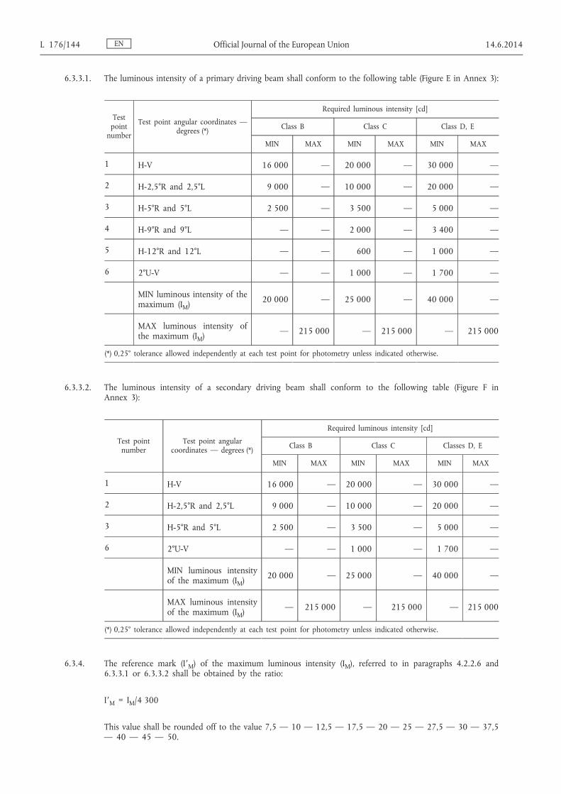