register your service manual - teeco...
TRANSCRIPT

Register Your Service Manual
Empire Comfort Systems Inc. 918 Freeburg Avenue Belleville, Illinois 62220-2623 618 233-7420 800 851-3153 Fax: 618 233-7097 800 443-8648
Name Date
Company Location
Mailing Address City, ST, zIP
Phone Fax: E-Mail *
My Company’s Products and Services: (Please check all that apply)
Sell Install Service ** LP Fired Products
Natural Gas Fired Products
Vented Heaters
Vent-Free Heaters
Vented Hearth
Vent-Free Hearth
Gas Grills
Please List Any Certifications You Currently Hold and the Year Earned:
Your Comments/Suggestions:
* Empire will send Sales Bulletins, Service Bulletins, and other product information to the e-mail address listed above. If you do not wish to receive these, please check this box.
** Empire’s web sites list servicing companies. If you wish to have your company/location listed, please provide the service contact information. This information will be published:
Contact Name Phone E-Mail
Physical Address City, ST, zIP (no PO Boxes)
Fax your completed form to Tech Services at 800 443-8648

2

Heater Technical Service And Troubleshooting Manual

4
Vent Free Heater Troubleshooting ..........................................................................................1:1SR Series Heater Troubleshooting .......................................................................................1:13BF Series Heater Troubleshooting .......................................................................................1:19Millivolt Direct Vent Heater Troubleshooting ........................................................................2:1DV210/215 Series Heater Troubleshooting .........................................................................2:15DV25/35 Series Heater Troubleshooting .............................................................................2:2124 Volt Direct Vent Heater Troubleshooting ..........................................................................3:1DV55SPP Heater Troubleshooting .......................................................................................3:13DV55IP Heater Troubleshooting .........................................................................................3:19DVC35 Heater Troubleshooting ...........................................................................................3:29DV-E Series Heater Troubleshooting ...................................................................................3:39Millivolt B Vent Heater Troubleshooting ...............................................................................4:1GWT Series Heater Troubleshooting ...................................................................................4:13Thermocouple B Vent Heater Troubleshooting ......................................................................5:1RH Series Heater Troubleshooting .......................................................................................5:1324 Volt B Vent Heater Troubleshooting ..................................................................................6:1FAW40SPP / IP Heater Troubleshooting ..............................................................................6:14FAW55SPP Heater Troubleshooting ....................................................................................6:22FAW55IP Heater Troubleshooting .......................................................................................6:26Floor Furnace Troubleshooting ..............................................................................................7:1Control Valves And Devices ...................................................................................................8:1Vented And Vent Free Sizing Charts ......................................................................................9:1Service Bulletins...................................................................................................................10:1Suggested Parts Lists ............................................................................................................11:1
Section Page
TABLE OF CONTENTS

Sec1:1
Vent Free Heater Troubleshooting
Sec1:2
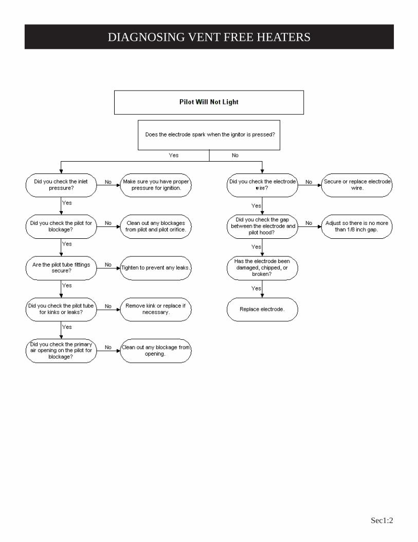
DIAGNOSING VENT FREE HEATERS

Sec1:3
DIAGNOSING VENT FREE HEATERS

Sec1:4
DIAGNOSING VENT FREE HEATERS

Sec1:5
DIAGNOSING VENT FREE HEATERS

Sec1:6
DIAGNOSING VENT FREE HEATERS

Sec1:7
DIAGNOSING VENT FREE HEATERS

Sec1:8
DIAGNOSING VENT FREE HEATERS

Sec1:9
DIAGNOSING VENT FREE HEATERS

Sec1:10

Sec1:11
SR Series Heater Troubleshooting
Sec1:12
FOR YOUR SAFETY READ BEFORE LIGHTINGWARNING: If you do not follow these instructions exactly, a fire or explosion may result caus-
ing property damage, personal injury or loss of life.
A. This appliance has a pilot which must be lighted by hand. When lighting the pilot, follow these instructions exactly.
B. BEFORE LIGHTING smell all around the appliance area for gas. Be sure to smell next to the floor because some gas is heavier than air and will settle on the floor.
WHAT TO DO IF YOU SMELL GAS• Do not try to light any appliance.• Do not touch any electrical switch; Do not use any phone in your building.• Immediately call your gas supplier from a neighbor's
phone. Follow the gas supplier's instructions.• If you cannot reach your gas supplier, call the fire
department.
C. Use only your hand to push in or turn the gas control knob. Never use tools. If the knob will not push in or turn by hand, don't try to repair it; call a qualified service technician. Force or attempted repair may result in a fire or explosion.
D. Do not use this appliance if any part has been under water. Immediately call a qualified service technician to inspect the appliance and to replace any part of the control system and any gas control which has been under water.
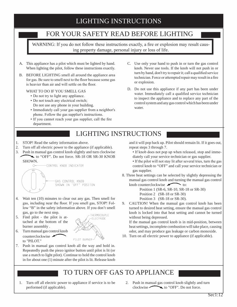
LIGHTING INSTRUCTIONS1. STOP! Read the safety information above.2. Turn off all electric power to the appliance (if applicable).3. Push in manual gas control knob slightly and turn clockwise
to “OFF”. Do not force. SR-18 OR SR-30 KNOB SHOWN.
4. Wait ten (10) minutes to clear out any gas. Then smell for gas, including near the floor. If you smell gas, STOP! Fol-low “B” in the safety information above. If you don’t smell gas, go to the next step.
5. Find pilot - the pilot is at-tached at the bottom of the burner assembly .
6. Turn manual gas control knob counterclockwise to "PILOT."
7. Push in manual gas control knob all the way and hold in. Repeatedly push the piezo ignitor button until pilot is lit (or use a match to light pilot). Continue to hold the control knob in for about one (1) minute after the pilot is lit. Release knob
and it will pop back up. Pilot should remain lit. If it goes out, repeat steps 3 through 7.
• If knob does not pop up when released, stop and imme-diately call your service technician or gas supplier.• If the pilot will not stay lit after several tries, turn the gas control knob to “OFF” and call your service technician or gas supplier.
8. Three heat settings can be selected by slightly depressing the manual gas control knob and turning the manual gas control knob counterclockwise to:
Position 1 (SR-6, SR-10, SR-18 or SR-30) Position 2 (SR-18 or SR-30) Position 3 (SR-18 or SR-30).
9. CAUTION! When the manual gas control knob has been turned to desired heat setting, ensure the manual gas control knob is locked into that heat setting and cannot be turned without being depressed.If the manual gas control knob is in mid-position, between heat settings, incomplete combustion will take place, causing odor, and may produce gas leakage or carbon monoxide.
10. Turn on all electric power to appliance (if applicable).
TO TURN OFF GAS TO APPLIANCE1. Turn off all electric power to appliance if service is to be
performed (if applicable).2. Push in manual gas control knob slightly and turn
clockwise to "OFF". Do not force.
LIGHTING INSTRUCTIONS

Sec1:13
Figure 1 (SR-6)
When facing the front of the appliance the following minimum clearances to combustible construction must be maintained.Left side 6 inches (152mm). Right side 6 inches 152mm).Do not install in alcove or closet. Rear wall 0 (0mm) inches. Ceiling 24 inches (610mm).Minimum vertical clearance from a projection above the appliance (shelves, window sills, etc.) 10 inches (254mm).Maximum horizontal extension of projection above the appliance 12 inches (305mm).Floor (top surface of carpeting, tile, etc.) 2 inches (51mm).
Provide adequate clearances around air openings.Adequate accessibility clearances for purposes of servicing and proper operation must be provided.
Figure 2 (SR-6)
CEILING
WINDOW SILL OR SHELF
24” MIN(610mm)
10” MIN(254mm)
12” MAX(305mm)
0” (0mm) CLEARANCETO REAR WALL
SIDE VIEW
2” MIN(51mm)
FLOOR
CEILING
SIDE WALL
WINDOW SILL OR SHELF
24” MIN(610mm)
10” MIN(254mm)
6” MIN(152mm)
6” MIN(152mm)
2” MIN(51mm)
FLOOR
When facing the front of the appliance the following minimum clearances to combustible construction must be maintained.Left side 6 inches (152mm). Right side 6 inches (152mm).Do not install in alcove or closet. Rear wall 0 inches (0mm). Ceiling 24 inches (610mm).Minimum vertical clearance from a projection above the appliance (shelves, window sills, etc.) 14 inches (356mm).Maximum horizontal extension of projection above the appliance 12 inches (305mm).Floor (top surface of carpeting, tile, etc.) 2 inches (51mm).
Provide adequate clearances around air openings.Adequate accessibility clearances for purposes of servicing and proper operation must be provided.
SR-6 CLEARANCES
SR-10 CLEARANCES

Sec1:14
Figure 3 (SR-10)
CEILING
WINDOW SILL OR SHELF
24” MIN(610mm)
14” MIN(356mm)
12” MAX(305mm)
0” (0mm) CLEARANCETO REAR WALL
SIDE VIEW
2” MIN(51mm)
FLOOR
Figure 4 (SR-10)
FLOOR
CEILING
SIDE WALL
24” MIN(610mm)
14” MIN(356mm)
6” MIN(152mm)
6” MIN(152mm)
2” MIN(51mm)
When facing the front of the appliance the following minimum clearances to combustible construction must be maintained.
Left side 6 inches (152mm). Right side 6 inches (152mm).Do not install in alcove or closet. Rear wall 0 inches (0mm). Ceiling 36 inches (914mm).Minimum vertical clearance from a projection above the appliance (shelves, window sills, etc.) 36 inches (914mm).Floor (top surface of carpeting, tile, etc.) 2 inches (51mm).
Provide adequate clearances around air openings.Adequate accessibility clearances for purposes of servicing and proper operation must be provided.
FLOOR
2” MIN(51mm)
6” (152mm)MIN
6” (152mm)MIN
SIDE WALL
CEILING
36” (914mm) MIN
Figure 5 (SR-18)
SR-18 CLEARANCES

Sec1:15
When facing the front of the appliance the following minimum clearances to combustible construction must be maintained.
Left side 8 inches (203mm). Right side 8 inches (203mm).Do not install in alcove or closet.Rear wall 0 inches (0mm). Ceiling 36 inches (914mm).Minimum vertical clearance from a projection above the appliance (shelves, window sills, etc.) 36 inches (914mm).Floor (top surface of carpeting, tile, etc.) 2 inches (51mm).
Provide adequate clearances around air openings.
Adequate accessibility clearances for purposes of servicing and proper operation must be provided.
CEILING
SIDE WALL
8” MIN. 8” MIN.
36” MIN
2” MIN
FLOOR
Figure 6 (SR-30)
SR-30 CLEARANCES
Sec1:16
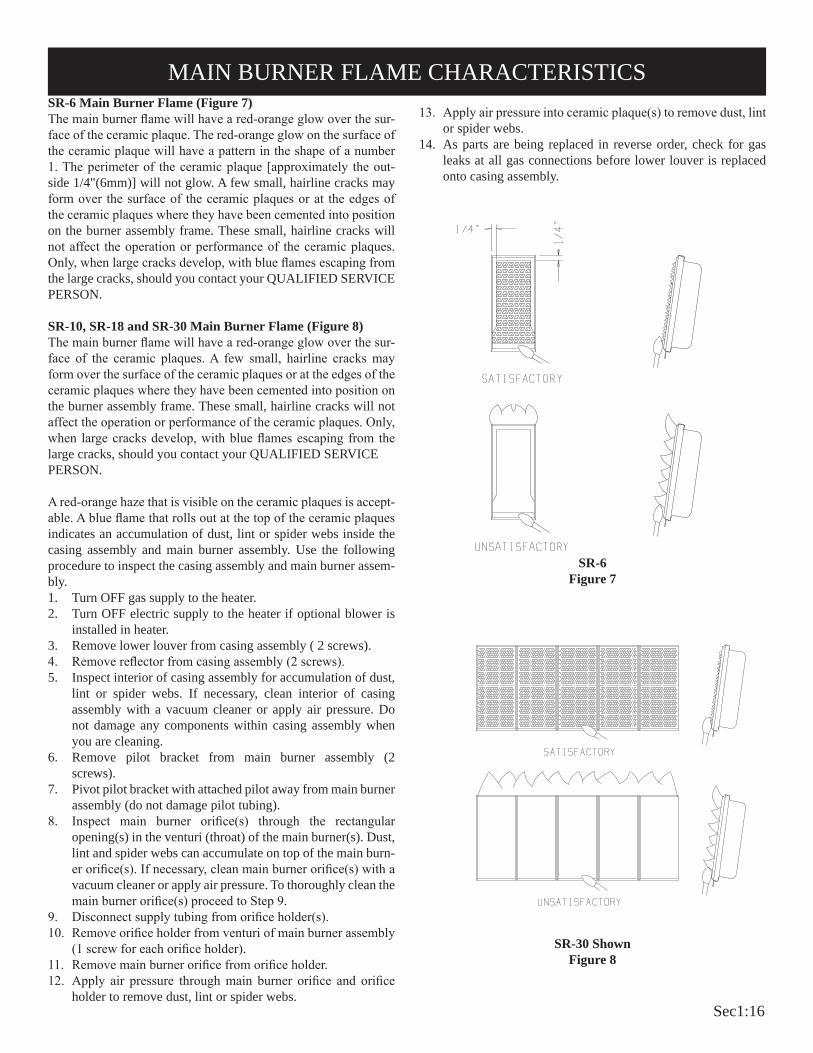
SR-6 Main Burner Flame (Figure 7)The main burner flame will have a red-orange glow over the sur-face of the ceramic plaque. The red-orange glow on the surface of the ceramic plaque will have a pattern in the shape of a number 1. The perimeter of the ceramic plaque [approximately the out-side 1/4"(6mm)] will not glow. A few small, hairline cracks may form over the surface of the ceramic plaques or at the edges of the ceramic plaques where they have been cemented into position on the burner assembly frame. These small, hairline cracks will not affect the operation or performance of the ceramic plaques. Only, when large cracks develop, with blue flames escaping from the large cracks, should you contact your QUALIFIED SERVICE PERSON.
SR-10, SR-18 and SR-30 Main Burner Flame (Figure 8)The main burner flame will have a red-orange glow over the sur-face of the ceramic plaques. A few small, hairline cracks may form over the surface of the ceramic plaques or at the edges of the ceramic plaques where they have been cemented into position on the burner assembly frame. These small, hairline cracks will not affect the operation or performance of the ceramic plaques. Only, when large cracks develop, with blue flames escaping from the large cracks, should you contact your QUALIFIED SERVICEPERSON.
A red-orange haze that is visible on the ceramic plaques is accept-able. A blue flame that rolls out at the top of the ceramic plaques indicates an accumulation of dust, lint or spider webs inside the casing assembly and main burner assembly. Use the following procedure to inspect the casing assembly and main burner assem-bly.1. Turn OFF gas supply to the heater.2. Turn OFF electric supply to the heater if optional blower is
installed in heater.3. Remove lower louver from casing assembly ( 2 screws).4. Remove reflector from casing assembly (2 screws).5. Inspect interior of casing assembly for accumulation of dust,
lint or spider webs. If necessary, clean interior of casing assembly with a vacuum cleaner or apply air pressure. Do not damage any components within casing assembly when you are cleaning.
6. Remove pilot bracket from main burner assembly (2 screws).
7. Pivot pilot bracket with attached pilot away from main burner assembly (do not damage pilot tubing).
8. Inspect main burner orifice(s) through the rectangular opening(s) in the venturi (throat) of the main burner(s). Dust, lint and spider webs can accumulate on top of the main burn-er orifice(s). If necessary, clean main burner orifice(s) with a vacuum cleaner or apply air pressure. To thoroughly clean the main burner orifice(s) proceed to Step 9.
9. Disconnect supply tubing from orifice holder(s).10. Remove orifice holder from venturi of main burner assembly
(1 screw for each orifice holder).11. Remove main burner orifice from orifice holder.12. Apply air pressure through main burner orifice and orifice
holder to remove dust, lint or spider webs.
SR-6 Figure 7
SR-30 ShownFigure 8
13. Apply air pressure into ceramic plaque(s) to remove dust, lint or spider webs.
14. As parts are being replaced in reverse order, check for gas leaks at all gas connections before lower louver is replaced onto casing assembly.
MAIN BURNER FLAME CHARACTERISTICS
Sec1:17
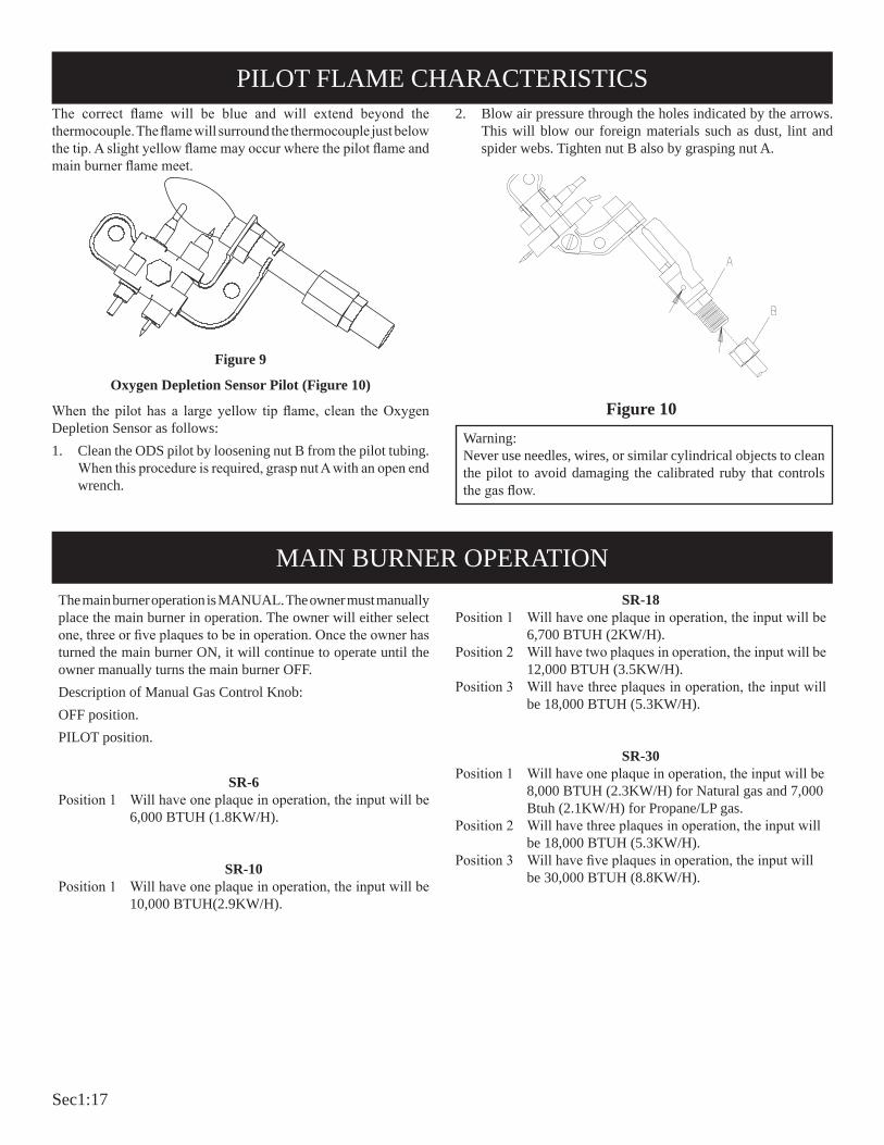
The correct flame will be blue and will extend beyond the thermocouple. The flame will surround the thermocouple just below the tip. A slight yellow flame may occur where the pilot flame and main burner flame meet.
Figure 9
Oxygen Depletion Sensor Pilot (Figure 10)
When the pilot has a large yellow tip flame, clean the Oxygen Depletion Sensor as follows:1. Clean the ODS pilot by loosening nut B from the pilot tubing.
When this procedure is required, grasp nut A with an open end wrench.
Warning: Never use needles, wires, or similar cylindrical objects to clean the pilot to avoid damaging the calibrated ruby that controls the gas flow.
2. Blow air pressure through the holes indicated by the arrows. This will blow our foreign materials such as dust, lint and spider webs. Tighten nut B also by grasping nut A.
The main burner operation is MANUAL. The owner must manually place the main burner in operation. The owner will either select one, three or five plaques to be in operation. Once the owner has turned the main burner ON, it will continue to operate until the owner manually turns the main burner OFF.Description of Manual Gas Control Knob:OFF position.PILOT position.
SR-6Position 1 Will have one plaque in operation, the input will be
6,000 BTUH (1.8KW/H).
SR-10Position 1 Will have one plaque in operation, the input will be
10,000 BTUH(2.9KW/H).
SR-18Position 1 Will have one plaque in operation, the input will be
6,700 BTUH (2KW/H).Position 2 Will have two plaques in operation, the input will be
12,000 BTUH (3.5KW/H).Position 3 Will have three plaques in operation, the input will
be 18,000 BTUH (5.3KW/H).
SR-30Position 1 Will have one plaque in operation, the input will be
8,000 BTUH (2.3KW/H) for Natural gas and 7,000 Btuh (2.1KW/H) for Propane/LP gas.
Position 2 Will have three plaques in operation, the input will be 18,000 BTUH (5.3KW/H).
Position 3 Will have five plaques in operation, the input will be 30,000 BTUH (8.8KW/H).
PILOT FLAME CHARACTERISTICS
MAIN BURNER OPERATION
Figure 10
Sec1:18
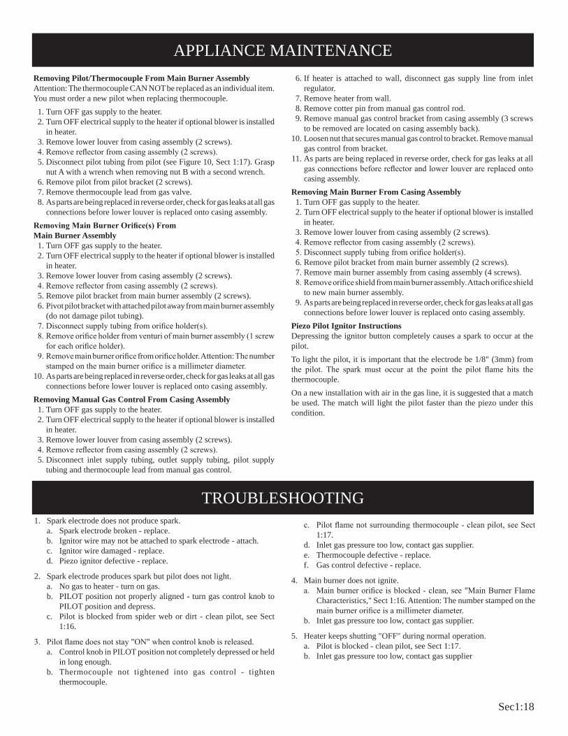
1. Spark electrode does not produce spark.a. Spark electrode broken - replace.b. Ignitor wire may not be attached to spark electrode - attach.c. Ignitor wire damaged - replace.d. Piezo ignitor defective - replace.
2. Spark electrode produces spark but pilot does not light.a. No gas to heater - turn on gas.b. PILOT position not properly aligned - turn gas control knob to
PILOT position and depress.c. Pilot is blocked from spider web or dirt - clean pilot, see Sect
1:16.
3. Pilot flame does not stay "ON" when control knob is released.a. Control knob in PILOT position not completely depressed or held
in long enough.b. Thermocouple not tightened into gas control - tighten
thermocouple.
c. Pilot flame not surrounding thermocouple - clean pilot, see Sect 1:17.
d. Inlet gas pressure too low, contact gas supplier.e. Thermocouple defective - replace.f. Gas control defective - replace.
4. Main burner does not ignite.a. Main burner orifice is blocked - clean, see "Main Burner Flame
Characteristics," Sect 1:16. Attention: The number stamped on the main burner orifice is a millimeter diameter.
b. Inlet gas pressure too low, contact gas supplier.
5. Heater keeps shutting "OFF" during normal operation.a. Pilot is blocked - clean pilot, see Sect 1:17.b. Inlet gas pressure too low, contact gas supplier
Removing Pilot/Thermocouple From Main Burner AssemblyAttention: The thermocouple CAN NOT be replaced as an individual item. You must order a new pilot when replacing thermocouple. 1. Turn OFF gas supply to the heater. 2. Turn OFF electrical supply to the heater if optional blower is installed
in heater. 3. Remove lower louver from casing assembly (2 screws). 4. Remove reflector from casing assembly (2 screws). 5. Disconnect pilot tubing from pilot (see Figure 10, Sect 1:17). Grasp
nut A with a wrench when removing nut B with a second wrench. 6. Remove pilot from pilot bracket (2 screws). 7. Remove thermocouple lead from gas valve. 8. As parts are being replaced in reverse order, check for gas leaks at all gas
connections before lower louver is replaced onto casing assembly.Removing Main Burner Orifice(s) From Main Burner Assembly 1. Turn OFF gas supply to the heater. 2. Turn OFF electrical supply to the heater if optional blower is installed
in heater. 3. Remove lower louver from casing assembly (2 screws). 4. Remove reflector from casing assembly (2 screws). 5. Remove pilot bracket from main burner assembly (2 screws). 6. Pivot pilot bracket with attached pilot away from main burner assembly
(do not damage pilot tubing). 7. Disconnect supply tubing from orifice holder(s). 8. Remove orifice holder from venturi of main burner assembly (1 screw
for each orifice holder). 9. Remove main burner orifice from orifice holder. Attention: The number
stamped on the main burner orifice is a millimeter diameter. 10. As parts are being replaced in reverse order, check for gas leaks at all gas
connections before lower louver is replaced onto casing assembly.Removing Manual Gas Control From Casing Assembly 1. Turn OFF gas supply to the heater. 2. Turn OFF electrical supply to the heater if optional blower is installed
in heater. 3. Remove lower louver from casing assembly (2 screws). 4. Remove reflector from casing assembly (2 screws). 5. Disconnect inlet supply tubing, outlet supply tubing, pilot supply
tubing and thermocouple lead from manual gas control.
6. If heater is attached to wall, disconnect gas supply line from inlet regulator.
7. Remove heater from wall. 8. Remove cotter pin from manual gas control rod. 9. Remove manual gas control bracket from casing assembly (3 screws
to be removed are located on casing assembly back). 10. Loosen nut that secures manual gas control to bracket. Remove manual
gas control from bracket. 11. As parts are being replaced in reverse order, check for gas leaks at all
gas connections before reflector and lower louver are replaced onto casing assembly.
Removing Main Burner From Casing Assembly 1. Turn OFF gas supply to the heater. 2. Turn OFF electrical supply to the heater if optional blower is installed
in heater. 3. Remove lower louver from casing assembly (2 screws). 4. Remove reflector from casing assembly (2 screws). 5. Disconnect supply tubing from orifice holder(s). 6. Remove pilot bracket from main burner assembly (2 screws). 7. Remove main burner assembly from casing assembly (4 screws). 8. Remove orifice shield from main burner assembly. Attach orifice shield
to new main burner assembly. 9. As parts are being replaced in reverse order, check for gas leaks at all gas
connections before lower louver is replaced onto casing assembly.Piezo Pilot Ignitor InstructionsDepressing the ignitor button completely causes a spark to occur at the pilot. To light the pilot, it is important that the electrode be 1/8" (3mm) from the pilot. The spark must occur at the point the pilot flame hits the thermocouple. On a new installation with air in the gas line, it is suggested that a match be used. The match will light the pilot faster than the piezo under this condition.
APPLIANCE MAINTENANCE
TROUBLESHOOTING

Sec1:19

Sec1:20

Sec1:21
BF Series Heater Troubleshooting

Sec1:22
TO TURN OFF GAS TO APPLIANCE
1. STOP! Read the safety information above.2. Set thermostat (gas control knob) to lowest setting.3. Turn off all electric power to the appliance (if applicable).4. Push in gas control knob slightly and turn clockwise
to "OFF". Do not force.
5. Wait ten (10) minutes to clear out any gas. Then smell for
gas, including near the floor. If you smell gas, STOP! Follow "B" in the safety information above. If you don't smell gas, go to the next step.
6. Find pilot - the pilot is attached at the bottom of the burner assembly .
7. Turn gas control knob counterclock-wise to "PILOT."
8. Push in gas control knob all the way and hold in. Repeatedly push the piezo ignitor button until pilot is lit (or use a match to light pilot). Continue to hold the control knob in for about one (1) minute after the pilot is lit. Release knob and it will pop back up. Pilot should remain
lit. If it goes out, repeat steps 4 through 8.• If knob does not pop up when released, stop and im-
mediately call your service technician or gas supplier. • If the pilot will not stay lit after several tries, turn the gas
control knob to "OFF" and call your service technician or gas supplier.
9. Attention! Gas control has an INTERLOCK latching device. When the pilot is initially lit and the safety magnet is ener-gized (pilot stays "ON") the INTERLOCK latching device becomes operative. If the gas control is turned to the "OFF" position or gas flow to the appliance is shut off, the pilot cannot be relighted until the safety magnet is de-energized (approximately 60 seconds). There will be an audible "click" when the safety magnet in the gas control is de-energized. Pilot can now be relighted. Repeat steps 4 through 8.
10. Turn gas control knob counterclockwise to "HI".
11. Turn on all electric power to appliance (if applicable).12. Set thermostat (gas control knob) to desired setting from "HI"
to "LO".
FOR YOUR SAFETY READ BEFORE LIGHTINGWARNING: If you do not follow these instructions exactly, a fire or explosion may result caus-
ing property damage, personal injury or loss of life.
A. This appliance has a pilot which must be lighted by hand. When lighting the pilot, follow these instructions exactly.
B. BEFORE LIGHTING smell all around the appliance area for gas. Be sure to smell next to the floor because some gas is heavier than air and will settle on the floor.
WHAT TO DO IF YOU SMELL GAS• Do not try to light any appliance.• Do not touch any electrical switch; do not use any phone in your building.• Immediately call your gas supplier from a neighbor's
phone. Follow the gas supplier's instructions.• If you cannot reach your gas supplier, call the fire depart-
ment.
C. Use only your hand to push in or turn the gas control knob. Never use tools. If the knob will not push in or turn by hand, don't try to repair it; call a qualified service technician. Force or attempted repair may result in a fire or explosion.
D. Do not use this appliance if any part has been under water. Immediately call a qualified service technician to inspect the appliance and to replace any part of the control system and any gas control which has been under water.
1. Set thermostat (gas control knob) to lowest setting.2. Turn off all electric power to appliance if service is to be
performed (if applicable).
3. Push in gas control knob slightly and turn clockwise to "OFF". Do not force.
LIGHTING INSTRUCTIONS
LIGHTING INSTRUCTIONS

Sec1:23
BF-30Figure 2
BF-10 and BF-20Figure 1
When facing the front of the appliance the following minimum clearances to combustible construction must be maintained.Do not install in alcove or closet.
Provide adequate clearances around air openings. Adequate accessibility clearances for purposes of servicing and proper operation must be provided.
BF-10/BF-20 BF-30Left side 5" (127mm) 8" (203mm)Right side 5" (127mm) 8" (203mm)Rear wall 0" (0mm) 0" (0mm)Ceiling 36" (914mm) 36" (914mm)Minimum vertical clearance from a projections above the appliance (shelves, window sills, etc.)
36" (914mm) 36" (914mm)
Floor (top surface of carpeting, tile, etc.) 2" (51mm) 2" (51mm)
CLEARANCES

Sec1:24
Piezo Pilot Ignitor InstructionsDepressing the ignitor button completely causes a spark to occur at the pilot. To light the pilot, it is important that the electrode be 1/8" (3mm) from the pilot. The spark must occur at the point the pilot flame hits the thermocouple. On a new installation with air in the gas line, it is suggested that a match be used. The match will light the pilot faster than the piezo under this condition.There will be a short blue inner flame with a much larger, lighter blue, secondary flame. The burner flame may have a small yellow tip when hot. Dust in the combustion air will produce an orange or red flame. Do not mistake the orange or red flame for an improper yellow flame. Clean main burner by applying compressed air into ports and throat of main burner.
Figure 3
Attention: BF-10, Natural or Propane gas has a front and rear air shutter.
BF-20, Propane gas only has a front air shutter. BF-30, Propane gas only has a front air shutter.
Air Shutter Adjustment (Figure 4)The air shutter on main burner is factory set at a 3/32" opening. If yellow flames occur on main burner loosen 1/4" screw on air shutter in order to increase air shutter opening. The slot on air shutter allows the air opening to be increased or decreased. Tighten 1/4" screw on air shutter after air shutter adjustment has been completed.
Figure 4
Cleaning Main Burner Orifice and Main Burner 1. Turn OFF gas supply to the heater.2. Turn OFF electric supply to the heater if optional blower,
SRB-18T or SRB-30T is installed in heater.3. Remove lower louver from casing assembly (2 screws).4. Remove reflector from casing assembly (2 screws).5. Inspect interior of casing assembly for accumulation of dust,
lint or spider webs. If necessary, clean interior of casing assembly with a vacuum cleaner or apply air pressure. Do not damage any components within casing assembly when you are cleaning.
6. Remove main burner orifice from orifice holder.7. Apply air pressure through main burner orifice and orifice
holder to remove dust, lint or spider webs.8. Apply air pressure into main burner to remove dust, lint or
spider webs.9. As parts are being replaced in reverse order, check for gas
leaks at all gas connections before lower louver is replaced onto casing assembly.
MAIN BURNER FLAME CHARACTERISTICS

Sec1:25
The correct flame will be blue and will extend beyond the thermo-couple. The flame will surround the thermocouple just below the tip. A slight yellow flame may occur where the pilot flame and main burner flame meet.
Figure 5
Oxygen Depletion Sensor Pilot (Figure 6)When the pilot has a large yellow tip flame, clean the Oxygen Depletion Sensor as follows:
1. Remove pilot from main burner assembly, see "Appliance Maintenance", Sect 1:26.
2. Apply air pressure through the holes in the pilot indicated by the arrows in Figure 6. This will blow out foreign materials such as dust, lint and spider webs.
Figure 6
Warning: Never use needles, wires, or similar cylindrical objects to clean the pilot to avoid damaging the calibrated ruby that controls the gas flow.
PILOT FLAME CHARACTERISTICS
1. Spark electrode does not produce spark.a. Spark electrode broken - replace.b. Ignitor wire may not be attached to spark electrode -
attach.c. Ignitor wire damaged - replace.d. Piezo ignitor defective - replace.
2. Spark electrode produces spark but pilot does not light.a. No gas to heater - turn on gas.b. PILOT position not properly aligned - turn gas control knob
to PILOT position and depress.c. Pilot is blocked from spider web or dirt - clean pilot, see
Figure 6.
3. Pilot flame does not stay "ON" when control knob is released.a. Control knob in PILOT position not completely depressed
or held in long enough.
b. INTERLOCK latching device is operative - see "Lighting Instructions," Sect 1:23, Step 9.
c. Thermocouple lead not tightened into gas control - tighten thermocouple lead.
d. Pilot flame not surrounding thermocouple - clean pilot, see Figure 6.
e. Inlet gas pressure too low, contact gas supplier.f. Thermocouple defective - replace pilot.g. Gas control defective - replace.
4. Main burner does not ignite.a. Main burner orifice is blocked - clean, see "Main Burner
Flame Characteristics," Sect 1:24. b. Inlet gas pressure too low, contact gas supplier.
5. Heater keeps shutting "OFF" during normal operation.a. Pilot is blocked - clean pilot, see Figure 6.b. Inlet gas pressure too low, contact gas supplier
SYMPTOMS - POSSIBLE CAUSES AND CORRECTIONS
TROUBLESHOOTING

Sec1:26
Glass Removal, Cleaning and Glass Replacement1. Remove chrome grill from reflector.2. Slide glass upward to remove glass from chrome grill.3. Clean glass with a non-abrasive household glass cleaner and
warm water. Gas fireplace glass cleaner can also be used.4. Align glass with rails on chrome grill and slide glass downward
into chrome grill.5. Attach chrome grill onto reflector. Warning: Do not operate unvented room heater without glass/
chrome grill attached to reflector.
To Remove Pilot From Main Burner Assembly1. Turn OFF gas supply to the heater.2. Turn OFF electrical supply to the heater if optional blower,
SRB-18T or SRB-30T is installed in heater.3. Remove lower louver from casing assembly (2 screws).4. Remove reflector from casing assembly (2 screws).5. Disconnect pilot tubing from pilot (see Figure 6, Sect 1:25).
Grasp nut A with a wrench when removing nut B with a second wrench.
6. Remove pilot from pilot bracket (2 nuts).7. As parts are being replaced in reverse order, check for gas
leaks at all gas connections before lower louver is replaced onto casing assembly.
To Remove Main Burner Orifice From Main Burner Assembly1. Turn off gas supply to the heater.2. Turn off electrical supply to the heater if optional blower,
SRB-18T or SRB-30T is installed in heater.3. Remove lower louver from casing assembly (2 screws).4. Remove reflector from casing assembly (2 screws).5. Disconnect supply tubing from orifice holder.6. Remove orifice holder from venturi of main burner assem-
bly.7. Remove main burner orifice from orifice holder.8. As parts are being replaced in reverse order, check for gas
leaks at all gas connections before lower louver is replaced onto casing assembly.
To Remove Gas Valve From Casing Assembly1. Turn OFF gas supply to the heater.2. Turn OFF electrical supply to the heater if optional blower,
SRB-18T or SRB-30T is installed in heater. 3. Remove lower louver from casing assembly (2 screws).4. Remove reflector from casing assembly (2 screws).5. Remove upper louver from casing assembly (2 screws).6. If installed, remove optional blower assembly (4 screws).7. Disconnect inlet supply tubing, outlet supply tubing, pilot
supply tubing and thermocouple lead from gas valve.8. If heater is attached to wall, disconnect gas supply line from
inlet regulator.9. Remove heater from wall.10. Remove gas valve bracket from casing assembly (4 screws to
be removed are located on casing assembly back).11. Remove hydraulic thermostat bulb from thermostat bulb clip
located at casing assembly bottom.12. Remove gas valve from gas valve bracket.13. As parts are being replaced in reverse order, check for gas leaks
at all gas connections before upper louver, reflector and lower louver are replaced onto casing assembly.
To Remove Main Burner From Casing Assembly1. Turn OFF gas supply to the heater.2. Turn OFF electrical supply to the heater if optional blower,
SRB-18T or SRB-30T is installed in heater. 3. Remove lower louver from casing assembly (2 screws).4. Remove reflector from casing assembly (2 screws).5. Disconnect supply tubing from orifice holder.6. Remove main burner assembly from casing assembly (2
screws).7. Remove air shutter(s) from main burner. BF-10 Natural and
LP has two (2) air shutters, BF-20 LP has one (1) air shutter and BF-30 LP has one (1) air shutter. Attach air shutter(s) to new main burner assembly.
8. As parts are being replaced in reverse order, check for gas leaks at all gas connections before lower louver is replaced onto casing assembly.
APPLIANCE MAINTENANCE

Sec1:27
SERVICE NOTES

Sec1:28
SERVICE NOTES

Sec1:29

Sec2:1
Millivolt Direct Vent Heater Troubleshooting

Sec2:2
DIAGNOSING MILLIVOLT DIRECT VENT HEATERS

Sec2:3
DIAGNOSING MILLIVOLT DIRECT VENT HEATERS

Sec2:4
DIAGNOSING MILLIVOLT DIRECT VENT HEATERS

Sec2:5
DIAGNOSING MILLIVOLT DIRECT VENT HEATERS
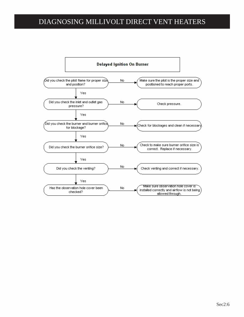
Sec2:6
DIAGNOSING MILLIVOLT DIRECT VENT HEATERS

Sec2:7
DIAGNOSING MILLIVOLT DIRECT VENT HEATERS

Sec2:8
DIAGNOSING MILLIVOLT DIRECT VENT HEATERS

Sec2:9
DIAGNOSING MILLIVOLT DIRECT VENT HEATERS
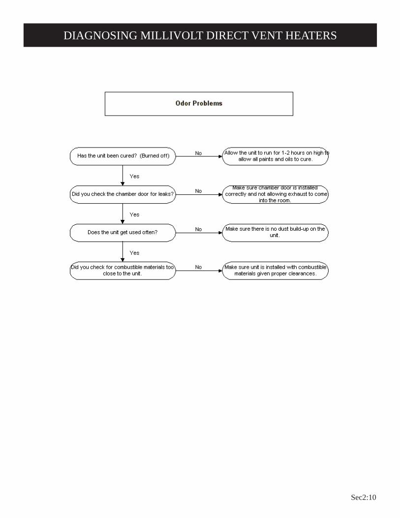
Sec2:10
DIAGNOSING MILLIVOLT DIRECT VENT HEATERS

Sec2:11
DIAGNOSING MILLIVOLT DIRECT VENT HEATERS

Sec2:12

Sec2:13
DV 210/215 Series Troubleshooting

Sec2:14
1. STOP! Read the safety information above.2. Set the thermostat to lowest setting.3. Turn off all electric power to the appliance (if appli-
cable).4. Remove control access panel (front panel).5. Push in gas control knob slightly and turn clockwise
to "OFF".
NOTE: Knob cannot be turned from "PILOT" to "OFF" unless knob is pushed in slightly. Do not force.
6. Wait ten (10) minutes to clear out any gas. Then smell for gas, including near the floor. If you smell gas, STOP! Follow "B" in the safety information above. If you don't smell gas, go to the next step.
7. Remove the pilot access cover located on the combustion chamber.
8. Find pilot - follow metal tube from gas control. The pilot is behind the pilot access cover.
9. Turn knob on gas control counterclockwise to "PILOT."10. Push in control knob all the way and hold in. Imme-
diately light the pilot with the Piezo Pilot Ignitor or a match. Continue to hold the control knob in for about one (1) minute after the pilot is lit. Release knob, and it will pop back up. Pilot should remain lit. If it goes out, repeat steps 5 through 10.
• If knob does not pop up when released, stop and immediately call your service technician or gas supplier.
• If the pilot will not stay lit after several tries, turn the gas control knob to "OFF" and call your service technician or gas supplier.
11. Replace pilot access cover.12. Turn gas control knob counterclockwise to
"ON."13. Replace control access panel (front panel).14. Turn on all electric power to the appliance (if appli-
cable).15. Set thermostat to desired setting.16. CAUTION: Pilot access cover must be kept tightly
closed during operation.
TO TURN OFF GAS TO APPLIANCE
FOR YOUR SAFETY READ BEFORE LIGHTING
WARNING: If you do not follow these instructions exactly, a fire or explo-sion may result causing property damage, personal injury or loss of life.
A. This appliance has a pilot which must be lighted by hand. When lighting the pilot, follow these instructions exactly.
B. BEFORE LIGHTING smell all around the appliance area for gas. Be sure to smell next to the floor because some gas is heavier than air and will settle on the floor.
WHAT TO DO IF YOU SMELL GAS• Do not try to light any appliance.• Do not touch any electrical switch; do not use any phone in your building.• Immediately call your gas supplier from a neighbor's
phone. Follow the gas supplier's instructions.
• If you cannot reach your gas supplier, call the fire department.
C. Use only your hand to push in or turn the gas control knob. Never use tools. If the knob will not push in or turn by hand, don't try to repair it; call a quali-fied service technician. Force or attempted repair may result in a fire or explosion.
D. Do not use this appliance if any part has been under water. Immediately call a qualified service techni-cian to inspect the appliance and to replace any part of the control system and any gas control which has been under water.
LIGHTING INSTRUCTIONS
1. Set the thermostat to lowest setting.2. Turn off all electric power to appliance if service is to be
performed (if applicable).3. Remove control access panel (front panel).
4. Push in gas control knob slightly and turn clockwise to "OFF." Do not force.
5. Replace control access panel (front panel).
PILOTBURNER
THERMOPILE
LIGHTING INSTRUCTIONS

Sec2:15
The vent terminal of a direct vent appliance, with an input of 10,000 Btu per hour (3 kW) or less shall be located at least 6" (150mm) from any air opening into a building, and such an appliance with an input over 10,000 Btu per hour (3 kW) but not over 50,000 Btu per hour (14.7 kW) shall be installed with a 9" (229mm) vent terminal clearance and the bottom of the vent terminal and the air intake shall be located at least 12" (305mm) above grade.
WARNING: The nearest point of the vent cap should be a minimum horizontal distant of six (6) feet (1.8m) from any pressure regulator. In case of regulator malfunction, the six (6) feet (1.8m) distance will reduce the chance of gas entering the vent cap.
1. In selecting a location for installation, it is necessary to provide adequate accessibility clearances for servicing and proper installation.
2. Although certified for 0 clearance to the floor , the unit is held in place by a wall bracket. Enough clearance [2" (51mm) suggested] to allow changing or adding floor covering is recommended. Other clearances to combustible construction:
Sides 1" (25mm) and 12" (305mm) from the top. 3. Note the position of the vent relative to the center of the unit.
The DV-210 has the vent in the center. The DV-215 vent is 2" (51mm) off center to the right.
4. The minimum distance from the center of the outside vent to the nearest outside corner or obstruction is 16" (406mm).
5. The DV-210/DV-215 minimum wall depth is 4 1/2" (114mm) and maximum wall depth is 13" (330mm). The use of tubes not supplied by the manufacturer result in unsatisfactory performance.
CLEARANCES

Sec2:16
These heating thermostats are specially designed for use on self-generating systems. They should never be used on line or low voltage A.C. circuits.Exterior Wall — The thermostat may be mounted on an exterior wall above the heater if it is located in the same stud space as the vent tubes and is a minimum of 6" (152mm) above the heater.Interior Wall — The thermostat should be installed on an inside wall away from the unit but in the same room. Note: Use 16 gauge wire to prevent excessive loss of millivolts.Proper operation depends on a good pilot flame. The flame must cover the top of the thermopile. Cleaning of the pilot orifice and burner may be required due to spiders.System CheckA millivolt meter is required to check the system. The millivolt readings should be:• Across the thermopile terminals, 400-450 millivolts with ther-
mostat OFF.• Across the thermopile terminals, 150-250 millivolts with ther-
mostat ON.• Across the thermostat wires at the valve, less than 30 millivolts
with thermostat ON.• Across the thermostat wires at the thermostat, less than 5 mil-
livolts with thermostat ON. (Strong winds, dirty pilot and low pressure will reduce readings.)
Piezo Pilot Ignitor InstructionsDepressing the piezo ignitor button completely causes a spark to occur at the pilot. This is a substitute for a match which requires opening the pilot hole cover.To light the pilot, it is important that the electrode be 1/8" (3mm) from the thermopile. The spark must occur at the point the burner flame hits the thermopile. The end of the electrode will be red hot with the pilot on.On a new installation with air in the gas line, it is suggested that a match be used. The match will light the pilot faster than the piezo under this condition.
Figure 1
THERMOSTAT LOCATION

Sec2:17
On the main burner, the burning gas forms a primary flame and a secondary flame. The primary flame is blue and about 3/16" (5mm) high. The secondary flame is very pale blue, 3 inches (76mm) to 5 inches (127mm) high. Dust in the combustion air will produce an orange flame. Do not mistake it for an improper yellow flame.
Figure 3
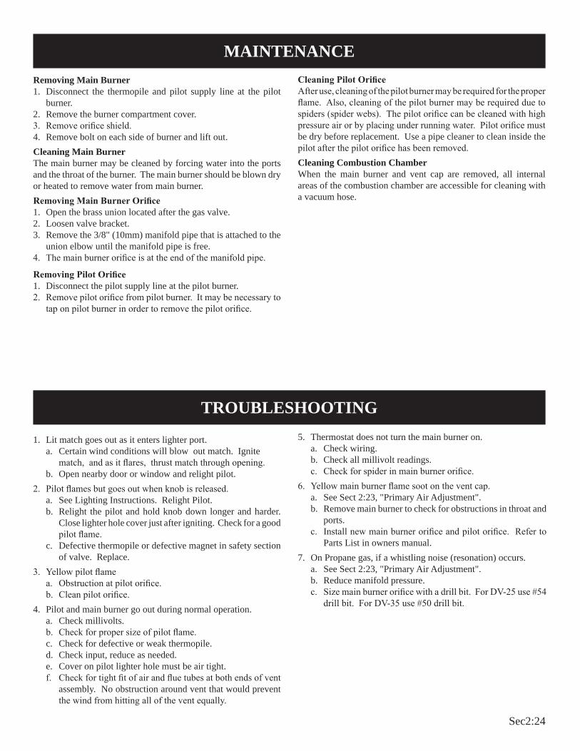
Steps in Removing Main Burner, Orifice and Valve1. Disconnect the thermopile and pilot supply line at the pilot
burner.2. Remove the burner compartment cover 5/16" (8mm) socket
suggested.3. Remove screw holding left side of burner and lift out.4. Main burner orifice is now accessible. Use 1/2" (13mm) box end
wrench to remove and apply non-hardening pipe dope sparingly to orifice threads when replaced.
5. To remove the entire gas valve the nut holding the orifice fitting to the chamber must be removed and the gas supply to the valve disconnected. After this, the valve and orifice elbow can be removed as a unit.
Cleaning The Pilot BurnerCleaning of the pilot may be an annual necessity due to spiders. After removing the supply tubing and orifice, use a pipe cleaner or wire to clean the entire internal part of the pilot.Cleaning the Combustion Chamber and Main BurnerWhen the main burner and vent cap are removed, all internal areas of the combustion chamber are accessible for cleaning with a vacuum hose. The main burner may be cleaned by forcing water into the ports and the throat of the burner. The burner should be blown dry or heated to dry all water out before reinstalling.
The pilot flame is blue and goes toward the main burner and thermopile horizontally. A slight yellow tip on the flame is normal. The pilot flame must surround and extend approximately 1/4" (6mm) beyond the thermopile, and must extend beyond the first row toward the second row of main burner ports.
Figure 2
PILOT FLAME CHARACTERISTICS
MAIN BURNER FLAME CHARACTERISTICS
MAINTENANCE
M AIN BURNER
PILOTFLAM E
BURNER CHANNEL
THERM OPILE

Sec2:18
1. Lit match goes out as it enters lighter port. a. Certain wind conditions will blow out match. Ignite
match, and as it flares, thrust match through opening. b. Open nearby door or window and relight pilot.2. Pilot flames but goes out when knob is released. a. See Lighting Instructions. Relight Pilot. b. Relight the pilot and hold knob down longer and harder.
Close lighter hole cover just after igniting. Check for a good pilot flame.
c. Defective thermopile or defective magnet in safety section of valve. Replace.
3. Yellow pilot flame. a. Obstruction at pilot orifice. b. Clean and properly size orifice.4. Pilot and main burner go out during normal operation. a. Check millivolts. b. Check for proper size of pilot flame.
c. Check for defective or weak thermopile. d. Check input, reduce as needed. e. Cover on pilot lighter hole must be air tight. f. Check for tight fit of air and flue tubes at both ends of vent
assembly. No obstruction around vent that would prevent the wind from hitting all of the vent equally.
5. Thermostat does not turn the main burner on. a. Check wiring. b. Check all millivolt readings. c. Check for spider in main burner orifice.6. Yellow main burner flame soot on the vent cap. a. Remove main burner to check for obstructions in throat,
ports and orifices. b. Install new main burner orifice and pilot orifice. Refer to
Parts List in Owners Manual.
TROUBLESHOOTING

Sec2:19

Sec2:20
DV 25/35 Series Troubleshooting

Sec2:21
FOR YOUR SAFETY READ BEFORE LIGHTINGWARNING: If you do not follow these instructions exactly, a fire or explosion may result caus-
ing property damage, personal injury or loss of life.
A. This appliance has a pilot which must be lighted by hand. When lighting the pilot, follow these instructions exactly.
B. BEFORE LIGHTING smell all around the appliance area for gas. Be sure to smell next to the floor because some gas is heavier than air and will settle on the floor.
WHAT TO DO IF YOU SMELL GAS• Do not try to light any appliance.• Do not touch any electrical switch; do not use any phone in your building.• Immediately call your gas supplier from a neighbor's
phone. Follow the gas supplier's instructions.• If you cannot reach your gas supplier, call the fire
department.C. Use only your hand to push in or turn the gas control
knob. Never use tools. If the knob will not push in or turn by hand, don't try to repair it; call a qualified service technician. Force or attempted repair may result in a fire or explosion.
D. Do not use this appliance if any part has been under water. Immediately call a qualified service technician to inspect the appliance and to replace any part of the control system and any gas control which has been under water.
TO TURN OFF GAS TO APPLIANCE1. Set the thermostat to lowest setting.2. Turn off all electric power to appliance if service is to be
performed (if applicable).3. Remove casing front assembly.
4. Push in gas control knob slightly and turn clockwise to "OFF." Do not force.
5. Replace casing front assembly.
1. STOP! Read the safety information above.2. Set the thermostat to lowest setting.3. Turn off all electric power to the appliance (if appli-
cable).4. Remove casing front assembly.5. Push in gas control knob slightly and turn clockwise
to "OFF".
NOTE: Knob cannot be turned from "PILOT" to "OFF" unless knob is pushed in slightly. Do not force.
6. Wait ten (10) minutes to clear out any gas. Then smell for gas, including near the floor. If you smell gas, STOP! Follow "B" in the safety information above. If you don't smell gas, go to the next step.
7. Remove the pilot access cover located on the combustion chamber.
8. Find pilot - follow metal tube
from gas control. The pilot is behind the pilot access cover.9. Turn knob on gas control counterclockwise to "PILOT."10. Push in control knob all the way and hold in. Imme-
diately light the pilot with the Piezo Pilot Ignitor or a match. Continue to hold the control knob in for about one (1) minute after the pilot is lit. Release knob, and it will pop back up. Pilot should remain lit. If it goes out, repeat steps 5 through 10.
• If knob does not pop up when released, stop and immediately call your service technician or gas supplier.
• If the pilot will not stay lit after several tries, turn the gas control knob to "OFF" and call your service technician or gas supplier.
11. Replace pilot access cover.12. Turn gas control knob counterclockwise to
"ON."13. Replace casing front assembly.14. Turn on all electric power to the appliance (if appli-
cable).15. Set thermostat to desired setting.16. CAUTION: Pilot access cover must be kept tightly closed
during operation.
LIGHTING INSTRUCTIONS
LIGHTING INSTRUCTIONS
Sec2:22
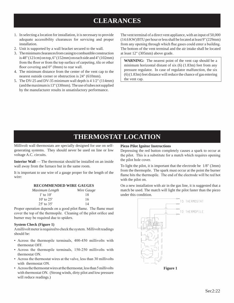
Millivolt wall thermostats are specially designed for use on self-generating systems. They should never be used on line or low voltage A.C. circuits.
Interior Wall — The thermostat should be installed on an inside wall away from the furnace but in the same room.
It is important to use wire of a gauge proper for the length of the wire:
RECOMMENDED WIRE GAUGES Maximum Length Wire Gauge 1' to 10' 18 10' to 25' 16 25' to 35' 14Proper operation depends on a good pilot flame. The flame must cover the top of the thermopile. Cleaning of the pilot orifice and burner may be required due to spiders.
System Check (Figure 1)A millivolt meter is required to check the system. Millivolt readings should be:
• Across the thermopile terminals, 400-450 millivolts with thermostat OFF.
• Across the thermopile terminals, 150-250 millivolts with thermostat ON.
• Across the thermostat wires at the valve, less than 30 millivolts with thermostat ON.
• Across the thermostat wires at the thermostat, less than 5 millivolts with thermostat ON. (Strong winds, dirty pilot and low pressure will reduce readings.)
Piezo Pilot Ignitor InstructionsDepressing the red button completely causes a spark to occur at the pilot. This is a substitute for a match which requires opening the pilot hole cover.To light the pilot, it is important that the electrode be 1/8" (3mm) from the thermopile. The spark must occur at the point the burner flame hits the thermopile. The end of the electrode will be red hot with the pilot on.On a new installation with air in the gas line, it is suggested that a match be used. The match will light the pilot faster than the piezo under this condition.
Figure 1
THERMOSTAT LOCATION
1. In selecting a location for installation, it is necessary to provide adequate accessibility clearances for servicing and proper installation.
2. Unit is supported by a wall bracket secured to the wall.3. The minimum clearances from casing to combustible construction
is 48" (121cm) on top, 6" (152mm) on each side and 4" (102mm) from the floor or from the top surface of carpeting, tile or other floor covering and 0" (0mm) to rear wall.
4. The minimum distance from the center of the vent cap to the nearest outside corner or obstruction is 24" (610mm).
5. The DV-25 and DV-35 minimum wall depth is 4 1/2" (114mm) (and the maximum is 13" (330mm). The use of tubes not supplied by the manufacturer results in unsatisfactory performance.
The vent terminal of a direct vent appliance, with an input of 50,000 (14.6 KW) BTU per hour or less shall be located at least 9" (229mm) from any opening through which flue gases could enter a building. The bottom of the vent terminal and the air intake shall be located at least 12" (305mm) above grade.
WARNING: The nearest point of the vent cap should be a minimum horizontal distant of six (6) (1.83m) feet from any pressure regulator. In case of regulator malfunction, the six (6) (1.83m) feet distance will reduce the chance of gas entering the vent cap.
CLEARANCES

Sec2:23
The correct flame will be almost horizontal, blue and will extend past the thermopile 1/4" (6mm). The flame will surround the thermopile just below the tip.On propane (LP-gas) slight yellow might occur where the pilot flame and burner flame meet.Natural gas pilots require adjusting when the inlet pressure is above 5" w.c. (1.25kPa) Turn adjustment screw clockwise to reduce flame.Propane (LP-gas) will not require adjusting.
Figure 2
There will be a short blue inner flame with a much larger lighter blue secondary flame. The burner flame may have a yellow tip when hot. See the burner drawing showing the approximate heights of each part of the flame. Dust in the combustion air will produce an orange or red flame. Do not mistake the orange or red flame for an improper yellow flame. After use, cleaning may be required for the proper flame.
Figure 3
Primary Air Adjustment (Figure 4) An air adjustment bolt is located on the chamber support bottom. The four inch (102mm) clearance between the furnace and the floor allows access to the air adjustment bolt. The air adjustment bolt is above the rectangular opening on the inner casing bottom.On Propane gas, if a whistling noise (resonation) occurs, screw air adjustment bolt into the chamber support in order to reduce the
amount of primary air. If the whistling noise (resonation) is not eliminated when the air adjustment bolt is screwed into the chamber support this may indicate the air adjustment bolt is misaligned. Grasp air adjustment bolt and pivot (push) air adjustment bolt away from yourself. Observe the main burner flame as you push air adjustment bolt and when the main burner flame begins to develop a yellow flame, you should stop pushing on the air adjustment bolt. Screw air adjustment bolt out of the chamber support until the yellow flame on the main burner is eliminated. The air adjustment bolt should now be properly aligned. The reduction in primary air will soften the main burner flame and will eliminate the whistling noise (resonation).On Propane or Natural gas, if a yellow flame occurs, screw air adjustment bolt out of the chamber support but do not completely remove air adjustment bolt from chamber support. The repositioning of the air adjustment bolt will increase the amount of primary air. The increase in primary air will sharpen the main burner flame and will eliminate the yellow flame.
Figure 4
PILOT FLAME CHARACTERISTICS
MAIN BURNER FLAME CHARACTERISTICS
Sec2:24
1. Lit match goes out as it enters lighter port.a. Certain wind conditions will blow out match. Ignite
match, and as it flares, thrust match through opening.b. Open nearby door or window and relight pilot.
2. Pilot flames but goes out when knob is released. a. See Lighting Instructions. Relight Pilot.b. Relight the pilot and hold knob down longer and harder.
Close lighter hole cover just after igniting. Check for a good pilot flame.
c. Defective thermopile or defective magnet in safety section of valve. Replace.
3. Yellow pilot flamea. Obstruction at pilot orifice.b. Clean pilot orifice.
4. Pilot and main burner go out during normal operation.a. Check millivolts.b. Check for proper size of pilot flame.c. Check for defective or weak thermopile.d. Check input, reduce as needed.e. Cover on pilot lighter hole must be air tight.f. Check for tight fit of air and flue tubes at both ends of vent
assembly. No obstruction around vent that would prevent the wind from hitting all of the vent equally.
5. Thermostat does not turn the main burner on.a. Check wiring.b. Check all millivolt readings.c. Check for spider in main burner orifice.
6. Yellow main burner flame soot on the vent cap.a. See Sect 2:23, "Primary Air Adjustment".b. Remove main burner to check for obstructions in throat and
ports.c. Install new main burner orifice and pilot orifice. Refer to
Parts List in owners manual. 7. On Propane gas, if a whistling noise (resonation) occurs.
a. See Sect 2:23, "Primary Air Adjustment".b. Reduce manifold pressure.c. Size main burner orifice with a drill bit. For DV-25 use #54
drill bit. For DV-35 use #50 drill bit.
Removing Main Burner1. Disconnect the thermopile and pilot supply line at the pilot
burner. 2. Remove the burner compartment cover. 3. Remove orifice shield.4. Remove bolt on each side of burner and lift out.Cleaning Main BurnerThe main burner may be cleaned by forcing water into the ports and the throat of the burner. The main burner should be blown dry or heated to remove water from main burner.Removing Main Burner Orifice1. Open the brass union located after the gas valve. 2. Loosen valve bracket. 3. Remove the 3/8" (10mm) manifold pipe that is attached to the
union elbow until the manifold pipe is free. 4. The main burner orifice is at the end of the manifold pipe.
Removing Pilot Orifice1. Disconnect the pilot supply line at the pilot burner.2. Remove pilot orifice from pilot burner. It may be necessary to
tap on pilot burner in order to remove the pilot orifice.
Cleaning Pilot OrificeAfter use, cleaning of the pilot burner may be required for the proper flame. Also, cleaning of the pilot burner may be required due to spiders (spider webs). The pilot orifice can be cleaned with high pressure air or by placing under running water. Pilot orifice must be dry before replacement. Use a pipe cleaner to clean inside the pilot after the pilot orifice has been removed.Cleaning Combustion Chamber When the main burner and vent cap are removed, all internal areas of the combustion chamber are accessible for cleaning with a vacuum hose.
MAINTENANCE
TROUBLESHOOTING
Sec2:25
SERVICE NOTES

Sec2:26
SERVICE NOTES

Sec2:27

Sec3:1
24 Volt Direct Vent Heater Troubleshooting

Sec3:2
DIAGNOSING 24 VOLT DIRECT VENT HEATERS

Sec3:3
DIAGNOSING 24 VOLT DIRECT VENT HEATERS

Sec3:4
DIAGNOSING 24 VOLT DIRECT VENT HEATERS

Sec3:5
DIAGNOSING 24 VOLT DIRECT VENT HEATERS

Sec3:6
DIAGNOSING 24 VOLT DIRECT VENT HEATERS

Sec3:7
DIAGNOSING 24 VOLT DIRECT VENT HEATERS

Sec3:8
DIAGNOSING 24 VOLT DIRECT VENT HEATERS

Sec3:9
DIAGNOSING 24 VOLT DIRECT VENT HEATERS

Sec3:10
DIAGNOSING 24 VOLT DIRECT VENT HEATERS

Sec3:11
DIAGNOSING 24 VOLT DIRECT VENT HEATERS

Sec3:12

Sec3:13
DV55SPP Heater Troubleshooting

Sec3:14
1. STOP! Read the safety information above. 2. Set the thermostat to lowest setting.3. Turn off all electric power to the appliance.4. Remove control access panel (lower front panel).5. Turn gas control knob clockwise to "OFF."
6. Wait ten (10) minutes to clear out any gas. Then smell for gas, including near the floor. If you smell gas, STOP! Follow "B" in the safety information above. If you don't smell gas, go to the next step.
7. Remove the pilot access cover located on the combustion chamber.
8. Find pilot - follow metal tube from gas control. The pilot is located between the two burner tubes behind the
pilot access cover.9. Turn gas control knob counterclockwise to
"PILOT."10. Push and hold red reset button down completely and
repeatedly push the ignitor button until the pilot burner is lit. Pilot may also be lit with a match. Continue to hold the red reset button down for about one (1) minute after the pilot is lit. Release button and it will pop back up. Pilot should remain lit. If it goes out, repeat steps 5 through 10.
• If button does not pop up when released, stop and immediately call a qualified service technician or gas supplier.
• If the pilot will not stay lit after several tries, turn the gas control knob to "OFF" and call your service technician or gas supplier.
11. Replace pilot access cover.
12. Turn gas control knob counterclockwise to "ON."
13. Replace control access panel (lower front panel).
14. Turn on all electric power to the appliance.
15. Set thermostat to desired setting.
FOR YOUR SAFETY READ BEFORE LIGHTINGWARNING: If you do not follow these instructions exactly, a fire or explosion may result
causing property damage, personal injury or loss of life.
A. This appliance has a pilot which must be lighted by hand. When lighting the pilot, follow these instructions exactly.
B. BEFORE LIGHTING smell all around the appliance area for gas. Be sure to smell next to the floor because some gas is heavier than air and will settle on the floor.
WHAT TO DO IF YOU SMELL GAS• Do not try to light any appliance.• Do not touch any electrical switch; do not use any phone in your building.• Immediately call your gas supplier from a neighbor's
phone. Follow the gas supplier's instructions.
• If you cannot reach your gas supplier, call the fire department.
C. Use only your hand to push in or turn the gas control knob. Never use tools. If the knob will not push in or turn by hand, don't try to repair it; call a qualified service technician. Force or attempted repair may result in a fire or explosion.
D. Do not use this appliance if any part has been under water. Immediately call a qualified service technician to inspect the appliance and to replace any part of the control system and any gas control which has been under water.
TO TURN OFF GAS TO APPLIANCE1. Set the thermostat to lowest setting.2. Turn off all electric power to appliance if service is to be
performed .3. Remove control access panel (lower front panel).
4. Push in gas control knob slightly and turn clockwise to "OFF." Do not force.
5. Replace control access panel (lower front panel).
LIGHTING INSTRUCTIONS
LIGHTING INSTRUCTIONS
Sec3:15
Clearances 1. In selecting a location for installation, it is necessary to provide
adequate accessibility clearances for servicing and proper installation.
2. The DV-55 minimum wall depth is 4 1/2 inches and maximum wall depth is 13 inches. The maximum wall depth may be extended to 19" (483mm) using the model DV-1190 extended flue kit. The use of tubes not supplied by the manufacturer results in unsatisfactory performance.
3. The DV-55 can be attached to the wall or recessed into the wall up to 4 inches in depth but the minimum 4 1/2 inches vent/air intake system wall depth must be maintained. Example: If furnace is recessed into the wall at a depth of 4 inches, the minimum wall depth must be 8 1/2 inches.
4. The wall in which the furnace is recessed has (0) zero clearance to the furnace sides and top.
5. When using side discharge registers, SOR-1 or SOK-1, the furnace cannot be recessed into the wall.
6. Clearance to sidewall or combustible material is 4 inches. 7. Ceiling clearance is 4 inches. 8. Floor and rear wall clearance is (0) zero inches. 9. Clearance of 18 inches is required to sidewall or combustible
material when flush mounted SOR-1, side outlet register is used. See Figure 4.
10. The minimum distance from the center of the vent cap to the nearest outside corner or obstruction is 24 inches.
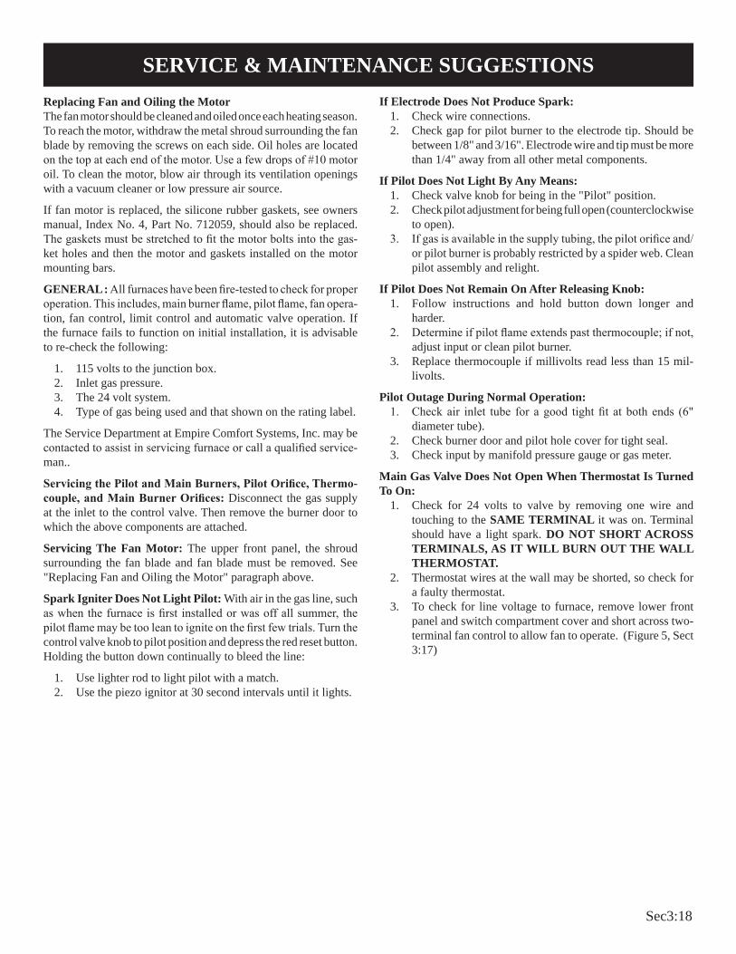
The vent terminal of a direct vent appliance with an input over 50,000 BTU per hour shall be located at least 12 inches from any opening through which flue gases could enter a building. The bot-tom of the vent terminal and the air intake shall be located at least 12 inches above grade.
WARNING: The nearest point of the vent cap should be a minimum horizontal distant of six (6) feet from any pressure regulator. In case of regulator malfunction, the six (6) feet distance will reduce the chance of gas entering the vent cap.
Figure 2
Figure 1
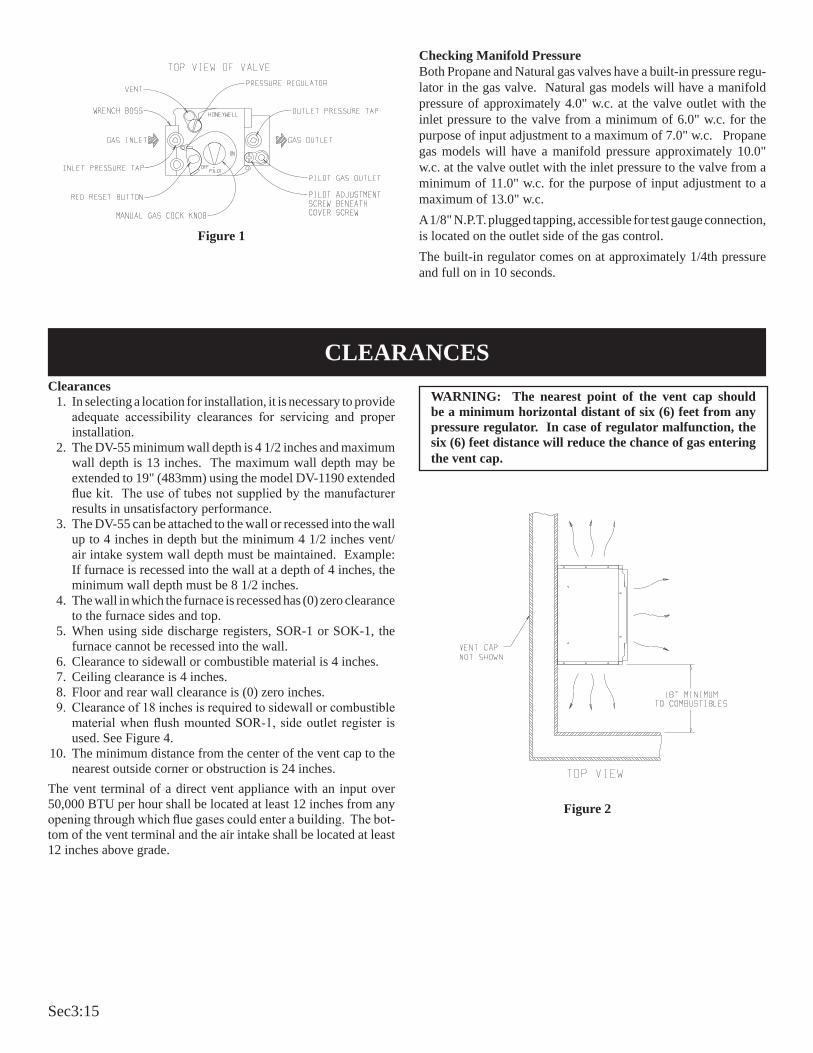
Checking Manifold PressureBoth Propane and Natural gas valves have a built-in pressure regu-lator in the gas valve. Natural gas models will have a manifold pressure of approximately 4.0" w.c. at the valve outlet with the inlet pressure to the valve from a minimum of 6.0" w.c. for the purpose of input adjustment to a maximum of 7.0" w.c. Propane gas models will have a manifold pressure approximately 10.0" w.c. at the valve outlet with the inlet pressure to the valve from a minimum of 11.0" w.c. for the purpose of input adjustment to a maximum of 13.0" w.c. A 1/8" N.P.T. plugged tapping, accessible for test gauge connection, is located on the outlet side of the gas control.The built-in regulator comes on at approximately 1/4th pressure and full on in 10 seconds.
CLEARANCES

Sec3:16
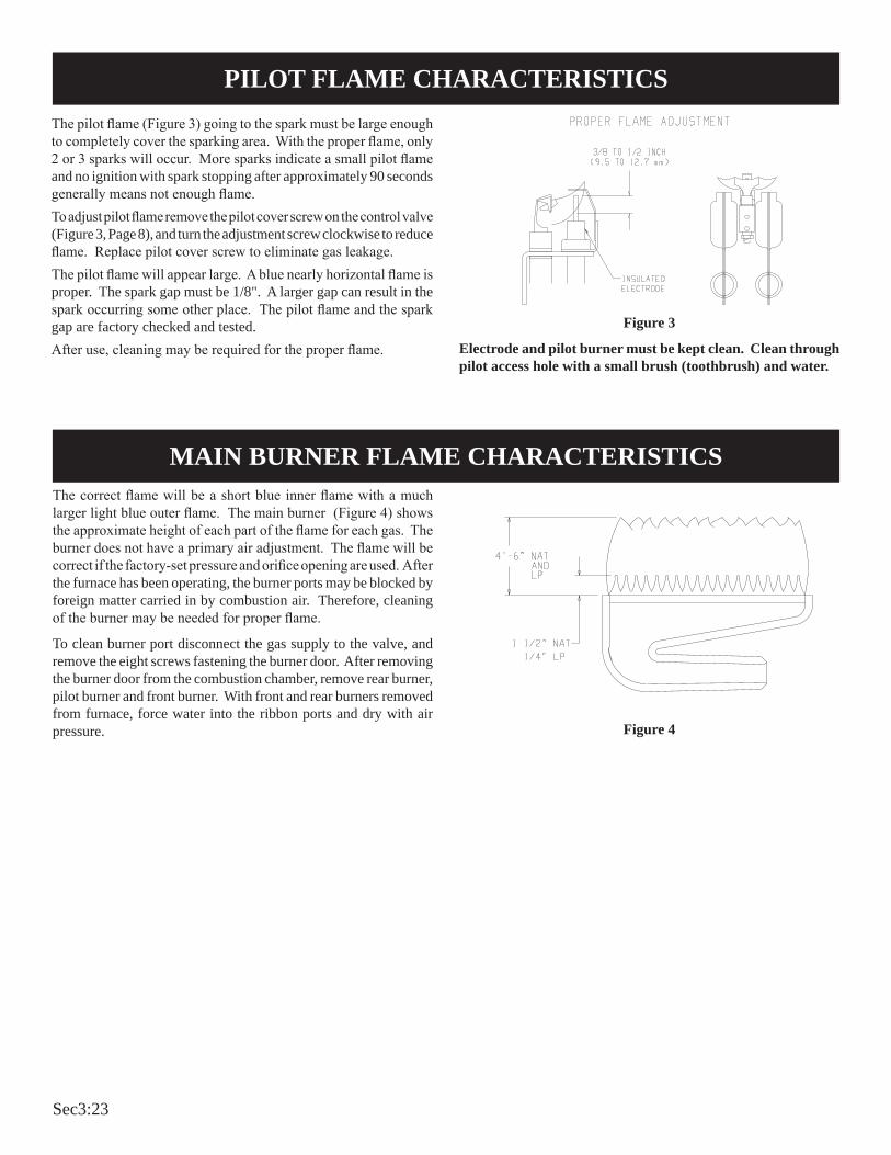
The correct flame will be a short blue inner flame with a much larger light blue outer flame. The main burner (Figure 4) shows the approximate height of each part of the flame for each gas. The burner does not have a primary air adjustment. The flame will be correct if the factory-set pressure and orifice opening are used. After the furnace has been operating, the burner ports may be blocked by foreign matter carried in by combustion air. Therefore, cleaning of the burner may be needed for proper flame.
To clean burner port disconnect the gas supply to the valve, and remove the eight screws fastening the burner door. After remov-ing the burner door from the combustion chamber, remove rear burner, pilot burner and front burner. With front and rear burners removed from furnace, force water into the ribbon ports and dry with air pressure.
The correct pilot flame (Figure 3) will be blue, extending past the thermocouple. The flame will surround the thermocouple just below the tip.
Natural gas pilots require adjusting when the inlet gas pressure is above 5" w.c. Remove the pilot cover screw on the control valve (Figure 3, page 8), and turn the adjustment screw clockwise to reduce flame. Replace pilot cover screw to eliminate gas leaking at that control valve opening.
LP gas (propane) will not require adjustment.
After use, cleaning may be required for the proper flame.
PROPER FLAME ADJUSTMENT
Figure 3
Figure 4
PILOT FLAME CHARACTERISTICS
MAIN BURNER FLAME CHARACTERISTICS

Sec3:17
Figure 5
WiringThe appliance, when installed, must be electrically grounded in ac-cordance with local codes or, in the absence of local codes, with the National Electrical Code, ANSI/NFPA 70 or Canadian Electrical Code, CSA C22.1, if an external electrical source is utilized. This appliance is equipped with a three-prong [grounding] plug for your protection against shock hazard and should be plugged directly into a properly grounded three-prong receptacle. Do not cut or remove the grounding prong from this plug. For an ungrounded receptacle, an adapter, which has two prongs and a wire for grounding, can be purchased, plugged into the ungrounded receptacle and its wire connected to the receptacle mounting screw. With this wire completing the ground, the appliance cord plug can be plugged into the adapter and be electrically grounded. A 7/8" hole is provided in the junction box for use with a conduit connector if local codes require this type of protection.Thermostat InstallationThe thermostat should be installed in the same room as the furnace 4' to 5' above the floor and away from another heat source (cooking stove, hot water heater, etc.) including walls and doorways with a heat source in an adjoining room. Do Not Install Thermostat on Outside Wall.
CAUTION: Label all wires prior to disconnection when servic-ing controls. Wiring errors can cause improper and dangerous operation. Verify proper operation after servicing.
WIRING
Sec3:18
Replacing Fan and Oiling the MotorThe fan motor should be cleaned and oiled once each heating season. To reach the motor, withdraw the metal shroud surrounding the fan blade by removing the screws on each side. Oil holes are located on the top at each end of the motor. Use a few drops of #10 motor oil. To clean the motor, blow air through its ventilation openings with a vacuum cleaner or low pressure air source.
If fan motor is replaced, the silicone rubber gaskets, see owners manual, Index No. 4, Part No. 712059, should also be replaced. The gaskets must be stretched to fit the motor bolts into the gas-ket holes and then the motor and gaskets installed on the motor mounting bars.
GENERAL : All furnaces have been fire-tested to check for proper operation. This includes, main burner flame, pilot flame, fan opera-tion, fan control, limit control and automatic valve operation. If the furnace fails to function on initial installation, it is advisable to re-check the following:
1. 115 volts to the junction box.2. Inlet gas pressure.3. The 24 volt system.4. Type of gas being used and that shown on the rating label.
The Service Department at Empire Comfort Systems, Inc. may be contacted to assist in servicing furnace or call a qualified service-man..
Servicing the Pilot and Main Burners, Pilot Orifice, Thermo-couple, and Main Burner Orifices: Disconnect the gas supply at the inlet to the control valve. Then remove the burner door to which the above components are attached.
Servicing The Fan Motor: The upper front panel, the shroud surrounding the fan blade and fan blade must be removed. See "Replacing Fan and Oiling the Motor" paragraph above.
Spark Igniter Does Not Light Pilot: With air in the gas line, such as when the furnace is first installed or was off all summer, the pilot flame may be too lean to ignite on the first few trials. Turn the control valve knob to pilot position and depress the red reset button. Holding the button down continually to bleed the line:
1. Use lighter rod to light pilot with a match. 2. Use the piezo ignitor at 30 second intervals until it lights.
If Electrode Does Not Produce Spark:1. Check wire connections.2. Check gap for pilot burner to the electrode tip. Should be
between 1/8" and 3/16". Electrode wire and tip must be more than 1/4" away from all other metal components.
If Pilot Does Not Light By Any Means:1. Check valve knob for being in the "Pilot" position.2. Check pilot adjustment for being full open (counterclockwise
to open).3. If gas is available in the supply tubing, the pilot orifice and/
or pilot burner is probably restricted by a spider web. Clean pilot assembly and relight.
If Pilot Does Not Remain On After Releasing Knob: 1. Follow instructions and hold button down longer and
harder.2. Determine if pilot flame extends past thermocouple; if not,
adjust input or clean pilot burner.3. Replace thermocouple if millivolts read less than 15 mil-
livolts.
Pilot Outage During Normal Operation:1. Check air inlet tube for a good tight fit at both ends (6"
diameter tube).2. Check burner door and pilot hole cover for tight seal.3. Check input by manifold pressure gauge or gas meter.
Main Gas Valve Does Not Open When Thermostat Is Turned To On:
1. Check for 24 volts to valve by removing one wire and touching to the SAME TERMINAL it was on. Terminal should have a light spark. DO NOT SHORT ACROSS TERMINALS, AS IT WILL BURN OUT THE WALL THERMOSTAT.
2. Thermostat wires at the wall may be shorted, so check for a faulty thermostat.
3. To check for line voltage to furnace, remove lower front panel and switch compartment cover and short across two-terminal fan control to allow fan to operate. (Figure 5, Sect 3:17)
SERVICE & MAINTENANCE SUGGESTIONS

Sec3:19

Sec3:20
DV55IP Heater Troubleshooting
Sec3:21
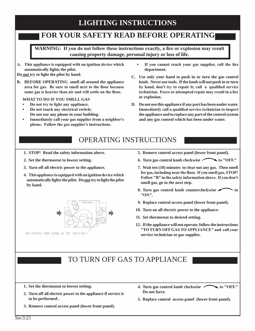
FOR YOUR SAFETY READ BEFORE OPERATINGWARNING: If you do not follow these instructions exactly, a fire or explosion may result
causing property damage, personal injury or loss of life.
A. This appliance is equipped with an ignition device which automatically lights the pilot.
Do not try to light the pilot by hand.
B. BEFORE OPERATING smell all around the appliance area for gas. Be sure to smell next to the floor because some gas is heavier than air and will settle on the floor.
WHAT TO DO IF YOU SMELL GAS• Do not try to light any appliance.• Do not touch any electrical switch; Do not use any phone in your building.• Immediately call your gas supplier from a neighbor's
phone. Follow the gas supplier's instructions.
• If you cannot reach your gas supplier, call the fire department.
C. Use only your hand to push in or turn the gas control knob. Never use tools. If the knob will not push in or turn by hand, don't try to repair it; call a qualified service technician. Force or attempted repair may result in a fire or explosion.
D. Do not use this appliance if any part has been under water. Immediately call a qualified service technician to inspect the appliance and to replace any part of the control system and any gas control which has been under water.
1. STOP! Read the safety information above.
2. Set the thermostat to lowest setting.
3. Turn off all electric power to the appliance.
4. This appliance is equipped with an ignition device which automatically lights the pilot. Do not try to light the pilot by hand.
5. Remove control access panel (lower front panel).
6. Turn gas control knob clockwise to "OFF."
7. Wait ten (10) minutes to clear out any gas. Then smell for gas, including near the floor. If you smell gas, STOP! Follow "B" in the safety information above. If you don't smell gas, go to the next step.
8. Turn gas control knob counterclockwise to "ON".
9. Replace control access panel (lower front panel).
10. Turn on all electric power to the appliance.
11. Set thermostat to desired setting.
12. If the appliance will not operate, follow the instructions "TO TURN OFF GAS TO APPLIANCE" and call your service technician or gas supplier.
OPERATING INSTRUCTIONS
TO TURN OFF GAS TO APPLIANCE
1. Set the thermostat to lowest setting.
2. Turn off all electric power to the appliance if service is to be performed .
3. Remove control access panel (lower front panel).
4. Turn gas control knob clockwise to "OFF." Do not force.
5. Replace control access panel (lower front panel).
LIGHTING INSTRUCTIONS

Sec3:22
Figure 1
Checking Manifold PressureBoth Propane and Natural gas valves have a built-in pressure regulator in the gas valve. Natural gas models will have a mani-fold pressure of approximately 3.5" w.c. at the valve outlet with the inlet pressure to the valve from a minimum of 5.0" w.c. for the purpose of input adjustment to a maximum of 7.0" w.c. Propane gas models will have a manifold pressure approximately 10.0" w.c. at the valve outlet with the inlet pressure to the valve from a minimum of 11.0" w.c. for the purpose of input adjustment to a maximum of 13.0" w.c. A 1/8" N.P.T. plugged tapping, accessible for test gauge connection, is located on the outlet side of the gas control.The built-in regulator comes on at approximately 1/4th pressure and full on in 10 seconds.Safety Lockout
S8600H module provides 100 percent shutoff, or safety lockout. If the pilot fails to light within 90 seconds, the control system will shut down. The control system must be reset by setting the thermostat below room temperature for one minute or by turning off power to the module for one minute.
Clearances 1. In selecting a location for installation, it is necessary to provide
adequate accessibility clearances for servicing and proper installation.
2. The DV-55 minimum wall depth is 4 1/2 inches and maximum wall depth is 13 inches. The maximum wall depth may be extended to 19" (483mm) using the model DV-1190 extended flue kit. The use of tubes not supplied by the manufacturer results in unsatisfactory performance.
3. The DV-55 can be attached to the wall or recessed into the wall up to 4 inches in depth but the minimum 4 1/2 inches vent/air intake system wall depth must be maintained. Example: If furnace is recessed into the wall at a depth of 4 inches, the minimum wall depth must be 8 1/2 inches.
4. The wall in which the furnace is recessed has (0) zero clearance to the furnace sides and top.
5. When using side discharge registers, SOR-1 or SOK-1, the furnace cannot be recessed into the wall.
6. Clearance to sidewall or combustible material is 4 inches. 7. Ceiling clearance is 4 inches. 8. Floor and rear wall clearance is (0) zero inches. 9. Clearance of 18 inches is required to sidewall or combustible
material when flush mounted SOR-1, side outlet register is used.
10. The minimum distance from the center of the vent cap to the nearest outside corner or obstruction is 24 inches.
The vent terminal of a direct vent appliance with an input over 50,000 BTU per hour shall be located at least 12 inches from any opening through which flue gases could enter a building. The bottom of the vent terminal and the air intake shall be located at least 12 inches above grade.
WARNING: The nearest point of the vent cap should be a minimum horizontal distant of six (6) feet from any pressure regulator. In case of regulator malfunction, the six (6) feet distance will reduce the chance of gas entering the vent cap.
Figure 2
CLEARANCES
Sec3:23
Figure 3
Electrode and pilot burner must be kept clean. Clean through pilot access hole with a small brush (toothbrush) and water.
The pilot flame (Figure 3) going to the spark must be large enough to completely cover the sparking area. With the proper flame, only 2 or 3 sparks will occur. More sparks indicate a small pilot flame and no ignition with spark stopping after approximately 90 seconds generally means not enough flame.To adjust pilot flame remove the pilot cover screw on the control valve (Figure 3, Page 8), and turn the adjustment screw clockwise to reduce flame. Replace pilot cover screw to eliminate gas leakage.The pilot flame will appear large. A blue nearly horizontal flame is proper. The spark gap must be 1/8". A larger gap can result in the spark occurring some other place. The pilot flame and the spark gap are factory checked and tested.After use, cleaning may be required for the proper flame.
The correct flame will be a short blue inner flame with a much larger light blue outer flame. The main burner (Figure 4) shows the approximate height of each part of the flame for each gas. The burner does not have a primary air adjustment. The flame will be correct if the factory-set pressure and orifice opening are used. After the furnace has been operating, the burner ports may be blocked by foreign matter carried in by combustion air. Therefore, cleaning of the burner may be needed for proper flame.
To clean burner port disconnect the gas supply to the valve, and remove the eight screws fastening the burner door. After removing the burner door from the combustion chamber, remove rear burner, pilot burner and front burner. With front and rear burners removed from furnace, force water into the ribbon ports and dry with air pressure. Figure 4
PILOT FLAME CHARACTERISTICS
MAIN BURNER FLAME CHARACTERISTICS

Sec3:24
WiringThe appliance, when installed, must be electrically grounded in accordance with local codes or, in the absence of local codes, with the National Electrical Code, ANSI/NFPA 70 or Canadian Electrical Code, CSA C22.1, if an external electrical source is utilized. This appliance is equipped with a three-prong [grounding] plug for your protection against shock hazard and should be plugged directly into a properly grounded three-prong receptacle. Do not cut or remove the grounding prong from this plug. For an ungrounded receptacle, an adapter, which has two prongs and a wire for grounding, can be purchased, plugged into the ungrounded receptacle and its wire connected to the receptacle mounting screw. With this wire completing the ground, the appliance cord plug can be plugged into the adapter and be electrically grounded. A 7/8" hole is provided in the junction box for use with a conduit connector if local codes require this type of protection.Thermostat InstallationThe thermostat should be installed in the same room as the furnace 4' to 5' above the floor and away from another heat source (cooking stove, hot water heater, etc.) including walls and doorways with a heat source in an adjoining room. Do Not Install Thermostat on Outside Wall.
CAUTION: Label all wires prior to disconnection when servicing controls. Wiring errors can cause improper and dangerous operation. Verify proper operation after servicing.
Figure 5
WIRING

Sec3:25
GENERAL: All furnaces have been fire-tested to check for proper operation. This includes, main burner flame, pilot flame, fan operation, fan control, limit control and automatic valve operation. If the furnace fails to function on initial installation, it is advisable to re-check the following:
1. 115 volts to the junction box.2. Inlet gas pressure.3. The 24 volt system.4. Type of gas being used and that shown on the rating label.
The Service Department at Empire Comfort Systems, Inc. may be contacted to assist in servicing furnace or call a qualified serviceman.
Servicing the Pilot and Main Burners, Pilot Orifice, and Main Burner Orifices: Disconnect the gas supply at the inlet to the control valve. Then remove the burner door to which the above components are attached.
Servicing The Fan Motor: The upper front panel, the shroud surrounding the fan blade and fan blade must be removed.
Replacing Fan and Oiling the MotorThe fan motor should be cleaned and oiled once each heating season. To reach the motor, withdraw the metal shroud surrounding the fan blade by removing the screws on each side. Oil holes are located on the top at each end of the motor. Use a few drops of #10 motor oil. To clean the motor, blow air through its ventilation openings with a vacuum cleaner or low pressure air source.
If fan motor is replaced, the silicone rubber gaskets, see owners manual, Index No. 4, Part No. 712059, should also be replaced. The gaskets must be stretched to fit the motor bolts into the gasket holes and then the motor and gaskets installed on the motor mounting bars.
S 8 6 0 0 H I N T E R M I T T E N T I G N I T I O N M O D U L E SPECIFICATIONSLockout timing is 90 seconds. Ignition timing is until pilot lights or lockout occurs.
Module shuts down and cuts power to gas control on flame failure. Gas control closes to provide 100 percent lockout on flame failure. Manual reset required.
ELECTRICAL RATINGS:Voltage and frequency: 20.5 to 28.5V (24V nom.) 60 Hz.Current rating: 0.2 A.Valve contact ratings (at 24 Vac): Run Inrush Pilot 1.0 A 10.0 A Main 1.0 A 10.0 A
SPARK GENERATOR OUTPUT: 13kV peak at 25 pf load.THERMOSTAT ANTICIPATOR SETTING: 0.2 A plus pilot valve rating
plus main valve rating. THERMOSTAT COMPATIBILITY: Standard models compatible with all
open-close switch type 24 Vac thermostats capable of supplying rated voltage and current to the module.
AMBIENT TEMPERATURE RATING: Minus 40 F to plus 175 F (minus 40 C to plus 79 C).
RELATIVE HUMIDITY RATING: 5 to 90 percent RH at 95 F.FLAME FAILURE RESPONSE TIME: 0.8 seconds at 1.0 uA flame
current.FLAME CURRENT: 1 uA, min.
CHECKOUTCheck out the gas control system: 1. At initial installation of the appliance. 2. As part of regular maintenance procedures. 3. As the first step in troubleshooting.
4. Any time work is done on the system.
STEP 1: Perform Visual Inspection. A. With power off, make sure all wiring connections are clean and
tight. B. Turn on power to appliance and ignition module. C. Open manual shutoff valves in the gas line to the appliance. D. Do gas leak test ahead of gas control if piping has been disturbed. GAS LEAK TEST: Paint pipe joints with rich soap and water solution.
Bubbles indicate gas leak. Tighten joints to stop leak.
STEP 2: Review Normal Operating Sequence and Module Specifications.
STEP 3: Reset the Module. A. Turn the thermostat to its lowest setting. B. Wait one minute. As you do Steps 4 and 5, watch for points where operation deviates
from normal. Refer to Troubleshooting Chart to correct problem.
STEP 4: Check Safety Lockout Operation. A. Turn gas supply off. B. Set thermostat above room temperature to call for heat. C. Watch for spark at pilot burner. D. Time length of spark operation. Maximum spark time is 90
seconds. E. Open manual gas cock and make sure no gas is flowing to pilot or
main burner. F. Set thermostat below room temperature and wait one minute before
continuing.
STEP 5: Check Normal Operation. A. Set thermostat above room temperature to call for heat. B. Make sure pilot lights smoothly when gas reaches the pilot burner. C. Make sure main burner lights smoothly without flashback. Make
sure burner operates smoothly without floating or lifting. D. If gas line has been disturbed, complete gas leak test. GAS LEAK TEST: Paint gas control gasket edges and all pipe
connections downstream of gas control, including pilot tubing connections, with rich soap and water solution. Bubbles indicate gas leaks. Tighten joints and screws or replace component to stop gas leak.
E. Turn thermostat below room temperature. Make sure main burner and pilot flames go out.
OPERATIONModule operation can be conveniently divided into two phases for S8600H. The phases are trial for ignition and main burner operation.
SERVICE & MAINTENANCE SUGGESTIONS
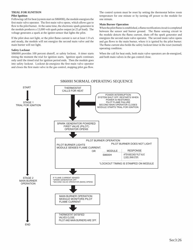
Sec3:26
TRIAL FOR IGNITIONPilot IgnitionFollowing call for heat (system start on S8600H), the module energizes the first main valve operator. The first main valve opens, which allows gas to flow to the pilot burner. At the same time, the electronic spark generator in the module produces a 13,000 volt spark pulse output (at 25 pf load). The voltage generates a spark at the igniter-sensor that lights the pilot.
If the pilot does not light, or the pilot flame current is not at least 1.0 uA and steady, the module will not energize the second main valve and the main burner will not light.
Safety LockoutS8600H provides 100 percent shutoff, or safety lockout. A timer starts timing the moment the trial for ignition starts. Ignition spark continues only until the timed trial for ignition period ends. Then the module goes into safety lockout. Lockout de-energizes the first main valve operator and closes the first main valve in the gas control, stopping pilot gas flow.
The control system must be reset by setting the thermostat below room temperature for one minute or by turning off power to the module for one minute.
Main Burner OperationWhen the pilot flame is established, a flame rectification circuit is completed between the sensor and burner ground. The flame sensing circuit in the module detects the flame current, shuts off the spark generator and energizes the second main valve operator. The second main valve opens and gas flows to the main burner, where it is ignited by the pilot burner. The flame current also holds the safety lockout timer in the reset (normal) operating condition.
When the call for heat ends, both main valve operators are de-energized, and both main valves in the gas control close.
STAGE 1TRIAL FOR IGNITION
IF FLAME CURRENT SENSED*SPARK GENERATOR OFF*SECOND VALVE OPERATOR (MAIN) OPENS
S8600H NORMAL OPERATING SEQUENCE

Sec3:27
Important 1. The following service procedures are provided as a general
guide. 2. Meter readings between gas control and ignition module must
be taken within the trial for ignition period. Once the igni-tion module locks out, the system must be reset by setting the thermostat down for at least one minute before continuing.
3. If any component does not function properly, make sure it is correctly installed and wired before replacing it.
4. The ignition module cannot be repaired. If it malfunctions, it must be replaced.
5. Only trained, experienced service technicians should service intermittent pilot systems.
Perform the CHECKOUT steps on page 15 as the first step in troubleshooting. Then check TROUBLESHOOTING GUIDE to pinpoint the cause of the problem. If troubleshooting indicates an ignition problem, see Ignition System Checks below to isolate and correct the problem.
Following troubleshooting, perform the CHECKOUT procedure (Sect 3:25) again to be sure system is operating normally.
Ignition System ChecksStep 1: Check ignition cable.Make sure: A. Ignition cable does not touch any metal surfaces. B. Ignition cable is no more than 36 inches long. C. Connections to the ignition module and to the igniter-sensor
are clean and tight. D. Ignition cable provides good electrical continuity.
Step 2: Check ignition system grounding. Nuisance shutdowns are often caused by a poor or erratic
ground. A. A common ground, usually supplied by the pilot burner
bracket, is required for the module and the pilot burner/igniter sensor.• Check for good metal-to-metal contact between the pilot
burner bracket and the main burner.• Check the ground lead from GND (BURNER) terminal on
the module to the pilot burner. Make sure connections are clean and tight. If the wire is damaged or deteriorated, replace it with No. 14-18 gauge, moisture-resistant, thermoplastic insulated wire with 105 C (221 F) minimum rating.• If flame rod or bracket are bent out of position, restore to
correct position.• Replace pilot burner/igniter sensor if insulator is
cracked.
Step 3: Check spark ignition circuit. You will need a short jumper wire made from ignition cable or other heavily insulated wire.
A. Close the manual gas valve. B. Disconnect the ignition cable at the SPARK terminal on the
module.
WARNINGWhen performing the following steps, do not touch stripped end of jumper or SPARK terminal. The ignition circuit generates 13,000 volts at 25 pf load and electrical shock can result.
C. Energize the module and immediately touch one end of the jumper firmly to the GND terminal on the module. Move the free end of the jumper slowly toward the SPARK terminal until a spark is established.
D. Pull the jumper slowly away from the terminal and note the length of the gap when sparking stops. Check table below.
Step 4: Check pilot flame current. A. Turn off furnace at thermostat. B. Disconnect main valve wire from the TH or MV terminal on
the gas control. C. Disconnect ground wire from GND (BURNER) terminal at
module. D. Connect a meter (dc microamp scale) in series with the ground
lead. • Disconnect ground lead from GND terminal on ignition
module.• Connect the black (negative) meter lead to the ignition
module GND (BURNER) terminal.• Connect the red (positive) meter lead to the free end of the
ground lead. E. Set thermostat to call for heat. The spark will light the pilot but
the main burner will not light because the main valve actuator is disconnected.
F. Read the meter. The flame sensor current must be steady and at least 1.0 uA.
G. If the reading is less than the minimum or unsteady,• Make sure pilot flame envelopes 3/8 to 1/2 inch of the flame
rod. • If necessary, adjust pilot flame by turning the pilot adjustment
screw on the gas control clockwise to decrease or counter-clockwise to increase pilot flame. Following adjustment, always replace pilot adjustment cover screw and tighten firmly to assure proper gas control operation.
• Check for cracked ceramic insulator, which can cause short to ground, and replace igniter-sensor if necessary.
• Make sure electrical connections are clean and tight. Replace damaged wire with moisture-resistant No. 18 wire rated for continuous duty up to 105 C (221 F).
H. Remove meter and reconnect all wires. Return system to normal operation before leaving job.
ARC LENGTH ACTIONNo arc or arc less than 1/8 inch
Arc 1/8 inch or longer
Check external fuse, if provided.Verify power at module input terminal.Replace module if fuse and power okay.
Voltage output is okay.
TROUBLESHOOTING
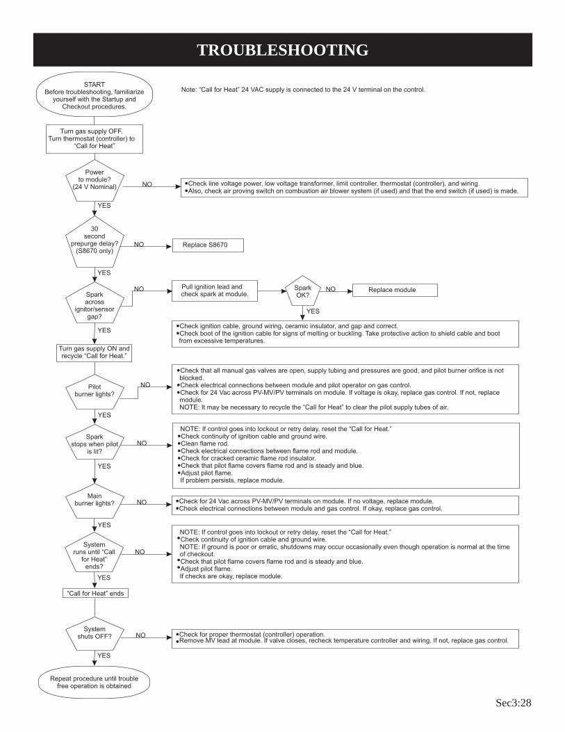
Sec3:28
TROUBLESHOOTING

Sec3:29
TROUBLESHOOTINGGreen LED Status Codes
Green LED Flash Code
(X + Y)a Indicates Next System Action Recommended Service ActionOFF No “Call for Heat” Not applicable NoneFlash Fast Startup-Flame sense calibration Not applicable NoneHeart Beat Normal operation Not applicable None3 Recycle
- Flame failed during runInitiate new trial for ignition. Flash code will remain through the ignition trial until flame is proved.
If system fails to light on next trial for ignition, check gas supply, pilot burner, flame sense wiring, contamination of flame rod, burner ground connection.
4 Flame sensed out of sequence If situation self corrects within 10 sec-onds, control returns to normal sequence. If flame out of sequence remains longer than 10 seconds, control goes to Flash code 6 + 4 (see below).
Check for pilot flame. Replace gas valve if pilot flame present. If no pilot flame, cycle “Call for Heat.” If error repeats, replace control.
7 Flame sense leakage to ground Control remains in wait mode. When the fault corrects, control resumes nor-mal operation after a one minute delay.
Check flame sense lead wire for damage or shorting. Check that flame rod is in proper position.Check flame rod ceramic for cracks, damage or tracking.
8 Low secondary voltage supply - below 15.5 Vac)
Control remains in wait mode. When the fault corrects, control resumes nor-mal operation after a one minute delay.
Check transformer and AC line for proper input voltage to the control. Check with full system load on the transformer.
6 + 2 Failed trial for ignition resulting in lockout
Remain in lockout until “Call for Heat” is cycled.
Check gas supply, pilot burner, spark and flame sense wiring, flame rod con-taminated or out of position, burner ground connection.
6 + 3 More than 5 flame failures during run on the same “Call for Heat” resulting in lockout
Remain in lockout until “Call for Heat” is cycled.
Check gas supply, pilot burner, flame sense wiring, contamination of flame rod, burner ground connection.
6 + 4 Flame sensed out of sequence - longer than 10 seconds
Control waits until flame is no longer sensed and then goes to soft lockout. Flash code continues. Control auto re-sets from soft lockout after one hour.
Check for pilot flame. Replace gas valve if pilot flame present. If no pilot flame, cycle “Call for Heat.” If error repeats, replace control.
ON Soft lockout due to error detected during self check sequences
Control auto resets from soft lockout af-ter one hour.
Reset by cycling “Call for Heat.” If er-ror repeats, replace the control.
aFlash Code Descriptions: - Flash Fast: Rapid blinking - Heartbeat: Constant 1/2 second bright 1/2 second dim cycles - A single flash code number signifies that the LED flashes X times at 2Hz, remains off for two seconds,
and then repeats the sequence. - X + Y flash codes signify that the LED flashes X times at 2Hz, remains off for two seconds, flashes Y
times at 2Hz, remains off for three seconds, and then repeats the sequence.

Sec3:30

Sec3:31
DVC35 Heater Troubleshooting

Sec3:32
DVC-35 SPP STANDING PILOT LIGHTING INSTRUCTIONS
FOR YOUR SAFETY READ BEFORE LIGHTING
WARNING: If you do not follow these instructions exactly, a fire or explosion may result causing property damage, personal injury or loss of life.
A. This appliance has a pilot which must be lighted by hand. When lighting the pilot, follow these instructions exactly.
B. BEFORE LIGHTING smell all around the appliance area for gas. Be sure to smell next to the floor because some gas is heavier than air and will settle on the floor.
WHAT TO DO IF YOU SMELL GAS •Do not try to light any appliance. •Do not touch any electrical switch; do not use any phone in your building. •Immediately call your gas supplier from a neighbor’s
phone, Follow the gas supplier’s instructions.
•If you cannot reach your gas supplier, call the fire department.
C. Use only your hand to push in or turn the gas control knob. Never use tools. If the knob will not push in or turn by hand, don’t try to repair it; call a qualified service technician. Force or attempted repair may result in a fire or explosion.
D. Do not use this appliance if any part has been under water. Immediately call a qualified service technician to inspect the appliance and to replace any part of the control system and any gas control which has been under water.
LIGHTING INSTRUCTIONS1. STOP! Read safety information above.2. Set the thermostat to lowest setting.3. Turn off all electric power to the appliance.4. Remove control access panel (lower front panel).5. Turn gas control knob clockwise to “OFF.”
6. Wait ten (10) minutes to clear out any gas. Then smell for gas, including near the floor. If you smell gas, STOP! Follow “B” in the safety information above. If you don’t smell gas, go to the next step.
7. Remove the pilot access cover located on the combustion chamber.
8. Find pilot - follow metal tube from gas control. The pilot is located between the two burner tubes behind the pilot access cover.
9. Turn gas control knob counterclockwise to “Pilot.”
10. Push and hold red reset button down completely and repeatedly push the ignitor button until the pilot burner is lit. Pilot may also be lit with a match. Continue to hold the red rest button down for about one (1) minute after the pilot is lit. Release button and it will pop back up. Pi-lot should remain lit. If it goes out, repeat step 5 through 10.
• If button does not pup up when released, stop and immediately call a qualified service technician or gas supplier.
• If the pilot will not stay lit after several tries, turn the gas control knob to “OFF” and call your service technician or gas supplier.
11. Replace pilot access cover.12. Turn gas control knob counterclockwise
to “ON.”13. Replace control access panel (lower front panel).14. Turn on all electric power to the appliance.15. Set thermostat to desired setting.
GAS CONTROL KNOB SHOWN IN “OFF” POSITION
THERMOCOUPLEPILOT BURNER
TO TURN OFF GAS TO APPLIANCE1. Set the thermostat to lowest setting.2. Turn off all electric power to appliance if service is to be
performed.3. Remove control access panel (lower front panel).
4. Push in gas control knob slightly and turn clockwise to “OFF.” Do not force.
5. Replace control access panel (lower front panel).

Sec3:33
Figure 1Checking Manifold PressureBoth Propane and Natural gas valves have a built-in pressure regulator in the gas valve. Natural gas models will have a manifold
pressure of approximately 4.0” w.c. (.996kPa) for DVC-35T and 3.5” w.c. (.871kPa) for DVC-35IPT at the valve outlet with the inlet pressure to the valve from a minimum of 5.0” w.c. (1.245kPa) for the purpose of input adjustment to a maximum of 7.0” w.c. (1.743kPa). Propane gas models will have a manifold pressure approximately 10.0” w.c. (2.49kPa) at the valve outlet with the inlet pressure to the valve from a minimum of 11.0” w.c. (2.739kPa) for the purpose of input adjustment to a maximum of 13.0” w.c. (3.237kPa). A 1/8” N.P.T. plugged tapping, accessible for test gauge connection, is located on the outlet side of the gas control.The built-in regulator comes on at approximately 1/4th pressure and full on in 10 seconds.
Clearances 1. In selecting a location for installation, it is necessary to provide
adequate accessibility clearances for servicing and proper installation. A front clearance of 36” is recommended. Do not block outlet or inlet air openings on the front grill.
2. The DV4T-59-1, 5” to 9” wall depth is the standard vent kit provided with the DVC-35T or DVC-35IPT. See Accessories Page 6 to order vent kits for wall depths of 8” to 12” or 12” to 19”. The use of tubes not supplied by the manufacturer results in unsatisfactory performance.
3. The DVC-35T and DVC-35IPT can be attached to the wall or recessed into the wall up to 9 1/2” in depth but the minimum 5” vent/air intake system wall depth must be maintained. Example: If furnace is recessed into the wall at a depth of 9 1/2”, the minimum wall depth behind the furnace must be 5”.
4. The wall in which the furnace is recessed has (0) zero clearance to the furnace sides and top.
5. When using side discharge registers, SOR-1 or SOK-1, the furnace cannot be recessed into the wall.
6. Clearance to sidewall or combustible material is 4”. 7. Ceiling clearance is 4”. 8. Floor and rear wall clearance is (0) zero inches. 9. Clearance of 18” is required to sidewall or combustible material
when flush mounted SOR-1, side outlet register is used. 10. The minimum distance from the center of the vent cap to the
nearest outside corner or obstruction is 12”.
Figure 2The vent terminal of this direct vent appliance shall be located at least 9” from any opening through which flue gases could enter a building. The bottom of the vent terminal and the air intake shall be located at least 12” above grade. See vent location, Figure 4.
WARNING: The nearest point of the vent cap should be a minimum horizontal distant of six (6) feet from any pressure regulator. In case of regulator malfunction, the six (6) feet distance will reduce the chance of gas entering the vent cap.
CLEARANCES

Sec3:34
DVC-35IP INTERMITTENT PILOT LIGHTING INSTRUCTIONSFOR YOUR SAFETY READ BEFORE LIGHTING
WARNING: If you do not follow these instructions exactly, a fire or explosion may result causing property damage, personal injury or loss of life.
A. This appl iance i s equipped wi th an ign i -tion device which automatically lights the pilot. Do NOT try to light the pilot by hand.
B. BEFORE LIGHTING smell all around the appliance area for gas. Be sure to smell next to the floor because some gas is heavier than air and will settle on the floor.
WHAT TO DO IF YOU SMELL GAS • Do not try to light any appliance. • Do not touch any electrical switch;
do not use any phone in your building. • Immediately call your gas supplier from a neighbor’s
phone, Follow the gas supplier’s instructions.
• If you cannot reach your gas supplier, call the fire de-partment.
C. Use only your hand to push in or turn the gas control knob. Never use tools. If the knob will not push in or turn by hand, don’t try to repair it; call a qualified service technician. Force or attempted repair may result in a fire or explosion.
D. Do not use this appliance if any part has been under water. Immediately call a qualified service technician to inspect the appliance and to replace any part of the control system and any gas control which has been under water.
OPERATING INSTRUCTIONS1. STOP! Read safety information above.2. Set the thermostat to lowest setting.3. Turn off all electric power to the appliance.4. This appliance is equipped with an ignition device which
automatically lights the pilot. Do not try to light the pilot by hand.
HONEYWELL IP SMART VALVE
5. Remove front panel door.6. Slide gas control switch to “OFF.”7. Wait ten (10) minutes to clear out any gas. Then smell
for gas, including near the floor. If you smell gas, STOP! Follow “B” in the safety information above. If you don’t smell gas, go to the next step.
8. Slide gas control switch to “ON.”9. Replace front panel door.10. Turn on all electric power to the appliance.11. Set thermostat to desired setting.12. If the appliance will not operate, follow the instructions,
“TO TURN OFF GAS TO APPLIANCE” and call your service technician or gas supplier.
IGN
ITO
RC
ON
TRO
L
OFF ON
GAS FLOW
GAS VALVE SHOWN IN OFF POSITION
TO TURN OFF GAS TO APPLIANCE1. Set the thermostat to lowest setting.2. Turn off all electric power to the appliance if service is to
be performed.
3. Remove front panel door.4. Slide gas control switch to “OFF.”5. Replace front panel door.

Sec3:35
PILOT FLAME CHARACTERISTICSThe correct pilot flame (Figure 3) will be blue, extending past the thermocouple. The flame will surround the thermocouple just below the tip.
Natural gas pilots require adjusting when the inlet gas pressure is above 5” w.c. (1.245kPa). Remove the pilot cover screw on the control valve, and turn the adjustment screw clockwise to reduce flame. Replace pilot cover screw to eliminate gas leaking at that control valve opening.
LP gas (Propane) will not require adjustment.
After use, cleaning may be required for the proper flame.
IP-Model PilotThis heater is using a Honeywell “Smart Valve” system for inter-mittent pilot ignition.
On a call for heat by the thermostat, this control turns on a 24 volt mini hot surface ignitor which lights a pilot that in turn lights the main burner. The gas valve used in this system is a step opening which opens at a lower pressure for ignition and then steps to a full inlet pressure of 4” H2O pressure on Natural gas and 10” H2O pressure on LP gas.
Pilot Flame Adjustment
The pilot flame should envelop 3/8 to 1/2 inch (10 to 13mm) of the tip of the flame rod. See Figure 3.
To adjust:1. Remove the pilot adjustment cover screw.2. Turn the inner adjustment screw clockwise
to decrease or counterclockwise t o increase pilot flame. Pilot adjustment is shipped at full flow rate. Turn the inner adjustment screw clockwise if the inlet pressure is too high.
3. Replace the cover screw after the adjustment to prevent gas leakage.
THERMOCOUPLE
BURNER
SPARK
ELECTRODEPILOT
STANDING PILOT
THERMOCOUPLE PILOT SHIELD
SPARK
ELECTRODE
PILOT LOCATION END VIEW
STANDING PILOT SHOWN
3/8” TO 1/2”
PILOT FLAME
GROUND
ELECTRODE
BURNER
PILOT
HOT SURFACE
IGNITOR
FLAME
ROD
IP-MODEL PILOT
Figure 3

Sec3:36
MAIN BURNER FLAME CHARACTERISTICSThe correct flame will be a short, blue inner flame with a much larger, light blue, outer flame. The burner does not have a primary air adjustment. The flame will be correct if the factory-set pressure and orifice opening are used. After the furnace has been operating, the burner ports may be blocked by foreign matter carried in by combustion air. Therefore, cleaning of the burner may be needed for proper flame.The clean burner port disconnect the gas supply to the valve, and remove the screws fastening the burner. After removing the burner door from the burner box, remove each main burner. Pilot mount-ing bracket will need to be unscrewed and moved out the way to remove all burners. Burners can be blown out using compressed air or by blowing through them. Be sure there is no lint or foreign debris blocking the burner ports. Reassemble using the same screws earlier removed and locate pilot in the same position as before and noted above. Figure 4
WIRINGThe appliance, when installed, must be electrically grounded in ac-cordance with local codes or, in the absence of local codes, with the National Electrical Code, ANSI/NFPA 70 or Canadian Electrical Code, CSA C22.1, if an external electrical source is utilized. This appliance is equipped with three-prong (grounding) plug for your protection against shock hazard and should be plugged directly into a properly grounded three-prong receptacle. Do not cut or remove the grounding prong from this plug. For an ungrounded receptacle, an adapter, which has two prongs and a wire for grounding, can be purchased, plugged into the ungrounded receptacle and its wire connected to the receptacle mounting screw. With this wire completing the ground, the appliance cord plug can be plugged into the adapter and be electrically grounded. A 7/8” hole is provided in the junction box for use with a conduit connector if local codes require this type of protection.
Thermostat InstallationThe thermostat should be installed in the same room as the furnace 4’ to 5’ above the floor and away from another heat source (cooking stove, hot water heater, etc.) including walls and doorways with a heat source in an adjoining room. Do Not Install Thermostat on Outside Wall.
CAUTION: Label all wires prior to disconnection when ser-vicing controls. Wiring errors can cause improper and danger-ous operation. Verify proper operation after servicing.
Figure 5
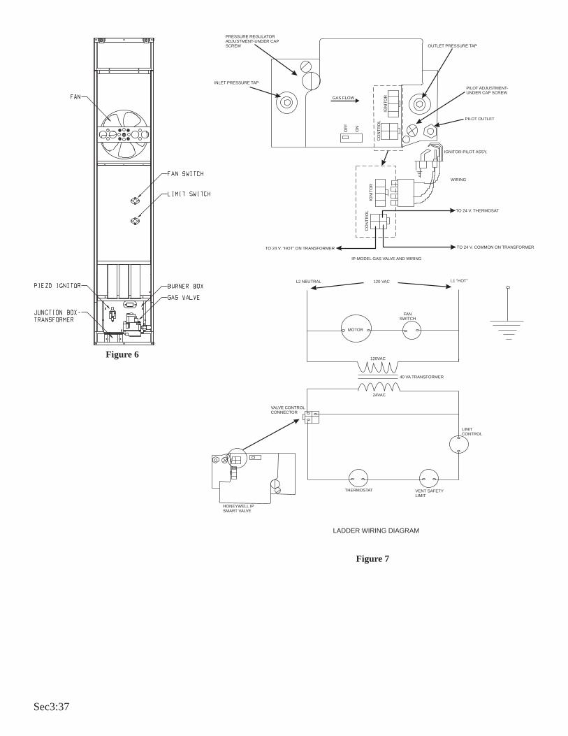
Sec3:37
GAS FLOW
OF
F
ON
CO
NT
RO
L
IGN
ITO
R
PRESSURE REGULATORADJUSTMENT-UNDER CAPSCREW
INLET PRESSURE TAP
OUTLET PRESSURE TAP
PILOT ADJUSTMENT-UNDER CAP SCREW
PILOT OUTLET
WIRING
TO 24 V. THERMOSAT
TO 24 V. COMMON ON TRANSFORMERTO 24 V. “HOT” ON TRANSFORMER
IGNITOR-PILOT ASSY.
IP-MODEL GAS VALVE AND WIRING
L2 NEUTRAL L1 “HOT”120 VAC
MOTOR
FANSWITCH
120VAC
40 VA TRANSFORMER
24VAC
VALVE CONTROLCONNECTOR
HONEYWELL IPSMART VALVE
THERMOSTAT VENT SAFETYLIMIT
LIMITCONTROL
CO
NT
RO
LIG
NIT
OR
LADDER WIRING DIAGRAM
Figure 6
Figure 7

Sec3:38
SERVICE AND MAINTENANCE SUGGESTIONSGENERAL: All furnaces have been fire-tested to check for proper operation. This includes, main burner flame, pilot flame, fan opera-tion, fan control, limit control and automatic valve operation. If the furnace fails to function on initial installation, it is advisable to re-check the following:
1. 115 volts to the junction box.2. Inlet gas pressure.3. The 24 volt system.4. Type of gas being used and that shown on the rating label.
The Service Department at Empire Comfort Systems, Inc. may be contacted to assist in servicing furnace.
Standing Pilot ModelServicing the Pilot and Main Burners, Pilot Orifice, Thermo-couple, and Main Burner Orifices: Disconnect the gas supply at the inlet to the control valve. Then remove the burner door to gain access to the above listed components.
Spark Igniter Does Not Light Pilot: With air in the gas line, such as when the furnace is first installed or was off all summer, the pilot flame may be too lean to ignite on the first few trials. Turn the control valve knob to pilot position and depress the red reset button. Holding the button down continually to bleed the line;
1. Use lighter rod to light pilot with a match
2. Use the piezo ignitor at 30 second intervals until it lights.
If Electrode Does Not Produce Spark:1. Check wire connections.
2. Check gap for pilot burner to the electrode tip. Should be between 1/8” (3mm) and 3/16” (4.8mm). Electrode wire and tip must be more than 1/4” (6.3mm) away from all other metal components.
If Pilot Does Not Light By Any Means:1. Check valve knob for being in the “Pilot” position.2. Check pilot adjustment for being full open (counterclockwise
to open).3. If gas is available in the supply tubing, the pilot orifice and/
or pilot burner is probably restricted by a spider web. Clean pilot assembly and relight.
If Pilot Does Not Remain On After Releasing Knob:1. Follow instructions and hold button down longer and hard-
er.
2. Determine if pilot flame extends past thermocouple; if not, adjust input or clean pilot burner.
3. Replace thermocouple if millivolts read less than 15 mil-livolts.
Pilot Outage During Normal Operation:1. Check air inlet tube for a good tight fit at both ends (6” diameter
tube).2. Check burner door and pilot hole cover for tight seal.3. Check input by manifold pressure gauge or gas meter.
Main Gas Valve Does Not Open when Thermostat Is Turned To On:
1. Check for 24 volts to valve by removing one wire and touching to the SAME TERMINAL it was on. Terminal should have a light spark. DO NOT SHORT ACROSS TERMINALS, AS IT WILL BURN OUT THE WALL THERMOSTAT.
2. Thermostat wires at the wall may be shorted, so check for a faulty thermostat.
3. To check for line voltage to furnace, remove front panel and short across two-terminal fan control to allow fan to operate (Figure 6).
Cleaning Combustion (Exchanger) AssemblyA QUALIFIED SERVICE PERSON should remove the combustion (exchanger) assembly and flue baffles. Apply air pressure to the inside of the combustion (exchanger) assembly and flue baffles in order to clear all passageways.
Oiling the MotorThe Fan motor should be cleaned and oiled once each heating season. Oil holes are located on the top at each end of the motor. Use a few drops of #10 motor oil. To clean the motor, blow air through its ventilation openings with a vacuum cleaner or low pressure air source.

Sec3:39
DVC-35IP INTERMITTENT PILOT SEQUENCE OF OPERATION
START
System Check
Trial forIgnition
Main BurnerOperation
END
Pilot Valve OpensIgnitor Powered
Flame SignalDetected
ThermostatCalls for Heat
Ignitor OFFMain Valve Opens
Internal CheckOK
Pilot Light and Flame isSensed During Trial For
Ignition (1)
Apply 24 VACTo Appliance
Main Pilot ValvesClose
Thermostat Call for HeatEnds
Flame SignalLost?
Pilot Valve Ignition OFFWait for Flame Signal to
Disappear
Pilot Valve ClosesIgnition OFF
Main PilotValves Close
Flame Lost MoreThan 5 Times inOne Call for Heat
5 Minute Retry Delay
3 Second Flame RecycleDelay
YES
NO
NO
YES
NO
YES
YES
NO
YES
NO
(1) Ignitor will turn OFF about 30 seconds into the trial for ignition if the pilot flame has not lit. It will turn back ON for the final 30 seconds of the 90 second trial for ignition. The pilot will be energized during the entire trial for ignition. This is normal operation for this gas ignition system.

Sec3:40
DVC-35IP INTERMITTENT PILOT SYSTEM TROUBLESHOOTING SEQUENCESTART IP SYSTEM TROUBLESHOOTING SEQUENCETurnOFFGasSupplyDisconnect System ControlHarnessSet Thermostat to Call forHeat
Check for Proper Voltage atControl Harness (See InsetA -Voltage Should be 24VBetween Thermostat and 24VCommon, and 24V Between24VCommonand24VHot.)
Plug Harness into SmartValveControlWait for Internal Check Delay(SV9501)
IgniterWarms UP and GlowsRed
Note: Igniter Will Cycle OFFand Back ONOnce During the90Second IgnitionTrial
TurnOnGasSupplyPilotBurnerLights
MainValveOpens andMainBurnerLights
System isOkay
CheckLine Voltage PowerLow Voltage TransformerLimit ControllerThermostatWiring
Unplug Pilot Burner Cable.Measure Voltage at SmartValue HSIElement Output (See Inset B) 24VNominal
Replace Igniter/Flame RodAssembly
Reconnect Pilot Burner Cable
Check that Pilot Gas is FlowingWait to Assure Pilot Gas Tubing isPurged.
Measure Voltage Between 24V Hotand 24V Common Leads toSmartValve Control. Must Measureat Least 19.5 VAC with IgniterPowered. See Inset A to IdentifyProper Lead. This Check Must beDone with the SmartValve ControlConnected and Igniter Powered.
Replace Igniter/Flame RodAssembly
Check that Pilot Flame MakesGood Contact with Pilot BurnerFlame RodCheck for Good ElectricalConnection Through the PilotTubingIf Both of the Above are Good,Replace Igniter/Flame Rod
Cycle Thermostat OFF and BackON
Main Burner Lights
YES
NO
NO
NO
NO
YES
YES
YES
Replace SmartValve Control
Reconnect Pilot Burner Cable
NO
Replace SmartValve ControlNO
Check Transformer and Line VoltSupply
NO
Replace SmartValve ControlNO
SmartValve System Troubleshooting SequenceNote: Before Troubleshooting, Become Familiar
with the Sequence of Operation
TMINSET A24 Volt
Thermostat
24Volts
24 VoltCommon 24
Volts24 VoltHot
EFTOutput
End Viewof ControlHarnessConnector
INSET BHSITerminals

Sec3:41
DV-E Series Heater Troubleshooting

Sec3:42
FOR YOUR SAFETY READ BEFORE OPERATINGWARNING: If you do not follow these instructions exactly, a fire or explosion may result caus-
ing property damage, personal injury or loss of life.
A. This appliance does not have a pilot. It is equipped with an ignition device which automatically lights the burner.
Do not try to light the burner by hand.
B. BEFORE OPERATING smell all around the appliance area for gas. Be sure to smell next to the floor because some gas is heavier than air and will settle on the floor.
WHAT TO DO IF YOU SMELL GAS• Do not try to light any appliance.• Do not touch any electrical switch; do not use any phone in your building.• Immediately call your gas supplier from a neighbor's
phone. Follow the gas supplier's instructions.
• If you cannot reach your gas supplier, call the fire department.
C. Use only your hand to push in or turn the gas control knob. Never use tools. If the knob will not push in or turn by hand, don't try to repair it; call a qualified service technician. Force or attempted repair may result in a fire or explosion.
D. Do not use this appliance if any part has been under water. Immediately call a qualified service technician to inspect the appliance and to replace any part of the control system and any gas control which has been under water.
1. STOP! Read the safety information above.
2. Set the thermostat to lowest setting.
3. Turn off all electric power to the appliance.
4. This appliance is equipped with an ignition device which automatically lights the burner. Do not try to light the burner by hand.
5. Remove control access panel (front panel).
6. Turn gas control knob clockwise to "OFF."
7. Wait ten (10) minutes to clear out any gas. Then smell for gas, including near the floor. If you smell gas, STOP! Follow "B" in the safety information above. If you don't smell gas, go to the next step.
8. Turn gas control knob counterclockwise to "ON".
9. Replace control access panel (front panel).
10. Turn on all electric power to the appliance.
11. Set thermostat to desired setting.
12. If the appliance will not operate, follow the instructions "TO TURN OFF GAS TO APPLIANCE" and call your service technician or gas supplier.
OPERATING INSTRUCTIONS
TO TURN OFF GAS TO APPLIANCE
1. Set the thermostat to lowest setting.
2. Turn off all electric power to the appliance if service is to be performed .
3. Remove control access panel (front panel).
4. Turn gas control knob clockwise to "OFF." Do not force.
5. Replace control access panel (front panel).
TOP VIEW
BACK END VIEW
GAS CONTROL LEVER SHOWNIN "OFF" POSITION
OFF
CONVERTIBLEREGULATOR
VINYL CAP
LIGHTING INSTRUCTIONS

Sec3:43
1. Pick a location on a wall with a clear space of 36" (91.4cm) high by 43" (109cm) wide in the room. In selecting a location for installation, it is necessary to provide adequate accessibility clearances for servicing and proper installation. Be sure to locate the unit close enough to a 115 VAC wall receptacle to properly power appliance.
2. Unit is supported by a wall bracket secured to the wall.3. When facing the front of the furnace the minimum clearances
from casing to combustible construction are 10" (254mm) on top, 3" (76mm) on each side, recommend 18" (457mm) on right side for servicing and 0" (0mm) from the floor and 0" (0mm) to rear wall.
4. The black flocked exhaust pipe, contained in DVE-1 Kit or DVE-2 Kit, has zero (0") inches (0mm) clearance to combustibles.
5. The minimum distance from the center of the vent cap to the nearest outside corner or obstruction is 12" (305mm).
6. The minimum wall depth is 2" (51mm) and the maximum is 10" (254mm) [or 32"(813mm) using the extended vent terminal kit accessory]. The use of vent tubes not supplied by the manufacturer may result in unsatisfactory performance.
The vent terminal of a direct vent appliance, with an input of 50,000 BTU (14.6KW) per hour or less shall be located at least 9" (229mm) from any opening through which flue gases could enter a building.The bottom of the exhaust vent terminal and the air intake shall be located at least 12" (305mm) above grade and must be vented outside.
WARNING: The nearest point of the vent cap should be a minimum horizontal distant of six (6) feet (1.83m) from any pressure regulator. In case of regulator malfunction, the six (6) feet (1.83m) distance will reduce the chance of gas entering the vent cap.
Installation on Rugs and TileIf this appliance is to be installed directly on carpeting, tile, or other combustible material, other than wood flooring, the appliance shall be installed on a metal or wood panel extending the full width and depth of the appliance.The base referred to above does not mean the fire-proof base as used on wood stoves. The protection is primarily for rugs that may be extremely thick and light-color tile that can discolor.
CLEARANCES

Sec3:44
The appliance, when installed, must be electrically grounded in ac-cordance with local codes or, in the absence of local codes, with the National Electrical Code, ANSI/NFPA 70 or Canadian Electrical Code, CSA C22.1, if an external electrical source is utilized. This appli-ance is equipped with a three-prong [grounding] plug for your protection against shock hazard and should be plugged directly into a properly grounded three-prong receptacle. Do not cut or remove the grounding prong from this plug. For an ungrounded receptacle, an adapter, which has two prongs and a wire for ground-ing, can be purchased, plugged into the ungrounded receptacle and its wire connected to the receptacle mounting screw. With this wire completing the ground, the appliance cord plug can be plugged into the adapter and be electrically grounded.
CAUTION: Label all wires prior to disconnection when servicing controls. Wiring errors can cause improper and dangerous operation. Verify proper operation after servicing.
Note: For testing flame sensor circuit use a micro-amp meter in series with sensor. Minimum current should be 1 micro-amp dur-ing operation. Be careful as flame sensor is in the 115VAC circuit. If current is below 1 micro-amp, remove sensor, clean with light sandpaper and retest. Note: This heater is equipped with a remote bulb electronic thermistor control located down low at the back of the furnace. Sometimes due
to field locations different air currents may effect the control sensing of the thermistor. This sensing bulb can be re-located if necessary to provided for better room air sensing and control. Replacement of Thermistor with 24 Volt Wall Thermostat 1. If furnace is installed, turn off gas supply and electric supply. 2. Remove casing front. 3. Remove black hose from front nipple on pressure switch. 4. Remove junction box cover (4 screws). 5. Please refer to wiring diagram for removal of the following
wires. 6. Internal Electronic Thermostat/Temperature Control
BoardAttention! No 24 volt wall thermostat wires are to be at-
tached to the internal electronic thermostat. 7. Control Board
A. Remove white wire form screw marked W.B. Remove yellow wire from screw marked C.C. Remove red wire from screw marked R.
8. Route (2) wires from any 24 volt wall thermostat through the casing back of furnace to the screws marked W and R on the control board.
9. Replace junction box cover (4 screws). 10. Replace black hose onto front nipple on pressure switch. 11. Replacement of thermistor with 24 volt wall thermostat is
completed.
CIRCULATING AIR BLOWER
WHT
FS
LS
RED
YEL
RED
BLK
1
PUR
PUR
INDUCERBLOWER
BLU
BLU
6
5
3
IF ANY OF THE ORIGINAL WIRE AS SUPPLIED WITH THEAPPLIANCE MUST BE REPLACED, IT MUST BE REPLACEDWITH A WIRE OF AT LEAST 105 ° C TEMPERATURE RATING.
LIMIT SWITCH
SECONDARY
FIELD INSTALLED
THERMOSTAT
24 VOLT115 VAC
SWITCHLIMIT
3A FUSEGND
BLACKWHITE
ON/OFF
ROLLOUT PRESSURESWITCH
R-8191
VALVEGAS
TRANSFORMER
24 VAC
PRIMARY 115 VAC
COMMON
DISCONNECT INTEGRAL THERMOSTAT "R", "W", AND "C" LEADS AND ATTACH WALL THERMOSTAT AS SHOWN
RW
5
6
PSRO
S RED
GRN
ORG
7
8
9
ORG
ELECTRONICTHERMOSTAT
INTEGRAL
WHT
YEL
RED
2
3
GRY
BRN
BRN
GV
GRY
24V
WHT
BLK
115
V
OPTIONAL WALL MOUNT THERMOSTAT
XFMRON/OFF BLACK NEUTRAL
RIBBEDINSULATION
BLACK HOTSMOOTHINSULATION
CIRCULATING AIRBLOWER MOTOR
RED LEDSTATUSLIGHT
IGN
HOT SURFACEIGNITOR
POWER SWITCH
INDUCER MOTOR
FLAME SENSOR
COMBUSTION AIR
ROS = ROLLOUT LIMIT SWITCHIGN = HOT SURFACE IGNITORPS = PRESSURE SWITCHXFMR = TRANSFORMER
CORDSET 115 VAC
FS = FLAME SENSOR
GV = GAS VALVELS = LIMIT SWITCH
4
2
4 1
WIRING
Figure 1

Sec3:45
The hot surface ignitor is energized and after a 17 second warm-up, the gas valve circuit is energized, opening the gas valve and igniting the burners. After burning for about 30 seconds, the circulating air blower comes on, delivering warm air to the room. If ignition does not occur, the ignition sequence is repeated again up to 2 more times. (3 trials for ignition-total)
3. After the furnace operates and satisfies the thermostat, the gas valve closes and the circulating air blower continues to run for about 2 minutes and then shuts off. The inducer blower runs for 5 seconds and shuts off.
If for any reason ignition and operation does not occur, the control board will blink the red fault status LED, a sequence code, indicating what to look for as a troubleshooting guide. If the red LED is ON but not blinking check the electronic temperature control to verify its operation. This can be easily done by disconnecting the 3 electronic temperature control leads from the main furnace board and using a pig tail jumper to connect R & W together on the board. If the furnace comes on and runs normally the temperature control board is malfunctioning. If the heater still does not come on, then the main furnace board is malfunctioning. Look for any fault codes below and verify the 3 amp fuse is not blown.
Your new furnace should provide many years of trouble free performance, however, a yearly inspection of the burners , flue passageways and the outlet vent assembly should be done. Be sure all passageways are open and clear of any obstruction, or soot build up. Be sure to shut off all power to the unit while performing this inspection. Periodically remove the circulating air filter and clean with water to remove all dirt. Shake dry and reinstall in unit.System Operation1. This furnace has an electronic thermostat and control board
to monitor the room temperature and then control the furnace operation to provide the best comfort and performance from a heating appliance. To operate unit turn ON/OFF switch to ON and then turn temperature control knob clockwise slowly till furnace turns on. For typical room comfort, the control knob should be pointed toward medium.
2. The furnace control board follows sequence of operation which allows for self diagnosis in the event there is a problem. The control then blinks a status light, a set number of blinks based on what problem has been encountered. When the furnace is on and there is a no fault condition, the red LED is on.
On a typical call for heat by the integral thermostat 24 VAC is applied to the W terminal on the board.
The inducer blower circuit is energized and the inducer blower comes on for 15 seconds pre-purging out any gas and closing the pressure switch.
Proper Main Burner FlameThe proper main burner flame will be a blue primary (inner) flame with a larger, lighter blue secondary (outer) blue flame.
Figure 2Cleaning Main Burner(s)Remove main burner(s) and apply air pressure inside the throat and ports of the main burner(s).Removing Main Burner(s)1. Remove front grill assembly.2. Remove burner compartment access panel (2 screws).3. Remove main burner(s) from burner compartment (2 screws
per main burner).
Removing Gas Valve1. Remove front grill assembly.2. Disconnect manifold union assembly at gas valve.3. Remove (2) two 24 volt wires from gas valve. Label wires prior
to disconnection from gas valve.4. Remove gas valve from gas valve bracket.Removing Main Burner Orifice(s)1. Remove front grill assembly.2. Remove burner compartment access panel (2 screws).3. Disconnect manifold union assembly.4. Disconnect manifold union assembly brackets (5 screws).Removing Ignitor and Flame Sensor1. Remove front grill assembly.2. Remove ignitor from burner compartment (2 screws).3. Remove flame sensor from burner compartment (1 screw).Cleaning Combustion (Exchanger) AssemblyA QUALIFIED SERVICE PERSON should remove the combustion (exchanger) assembly. Apply air pressure to the inside of the combustion (exchanger) assembly in order to clear all passageways.OilingThe blower motor has an oil hole located on each end of the motor. Use #20 motor oil only. It is best to oil the motor several times during the heating season using 2 or 3 drops each time.
MAINTENANCE
OPERATION AND TROUBLESHOOTING

Sec3:46
FURNACE CONTROL BOARDDIAGNOSTICS
FAULT SEQUENCE CODE — TROUBLE SHOOTING GUIDE
# of Blinks Fault Condition Fault CorrectionSteady On Control OK1 Flash Temperature limit switch is open -Check Circulating Air Blower Inlet or Grill Outlet for Blockage, Inducer
Blower/Circulating Air Blower Run to Cool Heat Exchanger and Limit-Check for Flame Roll Out Condition Causing Roll Out Limit Switch on Burner Box to Open
-Clean Circulating Air Filter2 Flashes Pressure switch is open with inducer on -Check Heat Exchanger and Flue System, Outlet and Inlet for Restriction
-Check Inducer Blower/Wheel for Operation/Airflow-Check Pressure Switch
3 Flashes Pressure switch is closed with inducer off -Check Pressure Switch and Replace4 Flashes Lockout due to failed ignition -Check for Broken Ignitor
-Check for Bent Ignitor Bracket - Ignitor too far from Burner-Check for Flame Sensor Malfunction/or False Ground-Check Gas Valve-Reset Thermostat
5 flashes L1/Neutral reversed or voltage not present on L1
-Shut Off Power to Unit and Dis-Connect Cordset Plug from Wall Recep-tacle.
Open Junction Box and Un-Reverse Polarity of Incoming Power LeadsRapid Flash Flame sense or internal control fault -Check Ignitor Operation
-Check Flame Sensor for Malfunction or False Grounding-Check Gas Valve-Reset Thermostat
Note: If the hot surface ignitor is to be replaced, be sure to disconnect all power to the unit. Be very careful in handling the new ignitor as they are fragile and can be broken easily if hit or dropped.

Sec3:47
SERVICE NOTES
Sec3:48
SERVICE NOTES

Sec3:49

Sec4:1
Millivolt B Vent Heater Troubleshooting
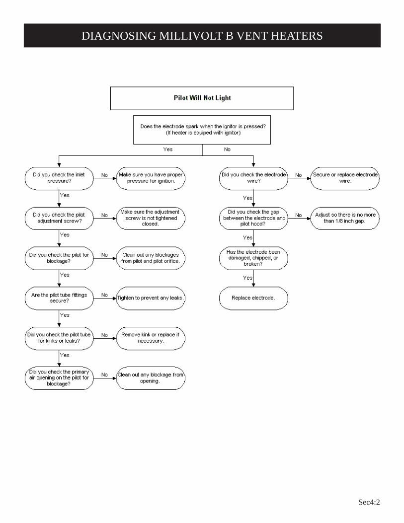
Sec4:2
DIAGNOSING MILLIVOLT B VENT HEATERS

Sec4:3
DIAGNOSING MILLIVOLT B VENT HEATERS
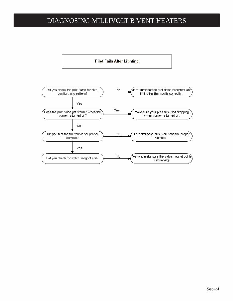
Sec4:4
DIAGNOSING MILLIVOLT B VENT HEATERS

Sec4:5
DIAGNOSING MILLIVOLT B VENT HEATERS

Sec4:6
DIAGNOSING MILLIVOLT B VENT HEATERS
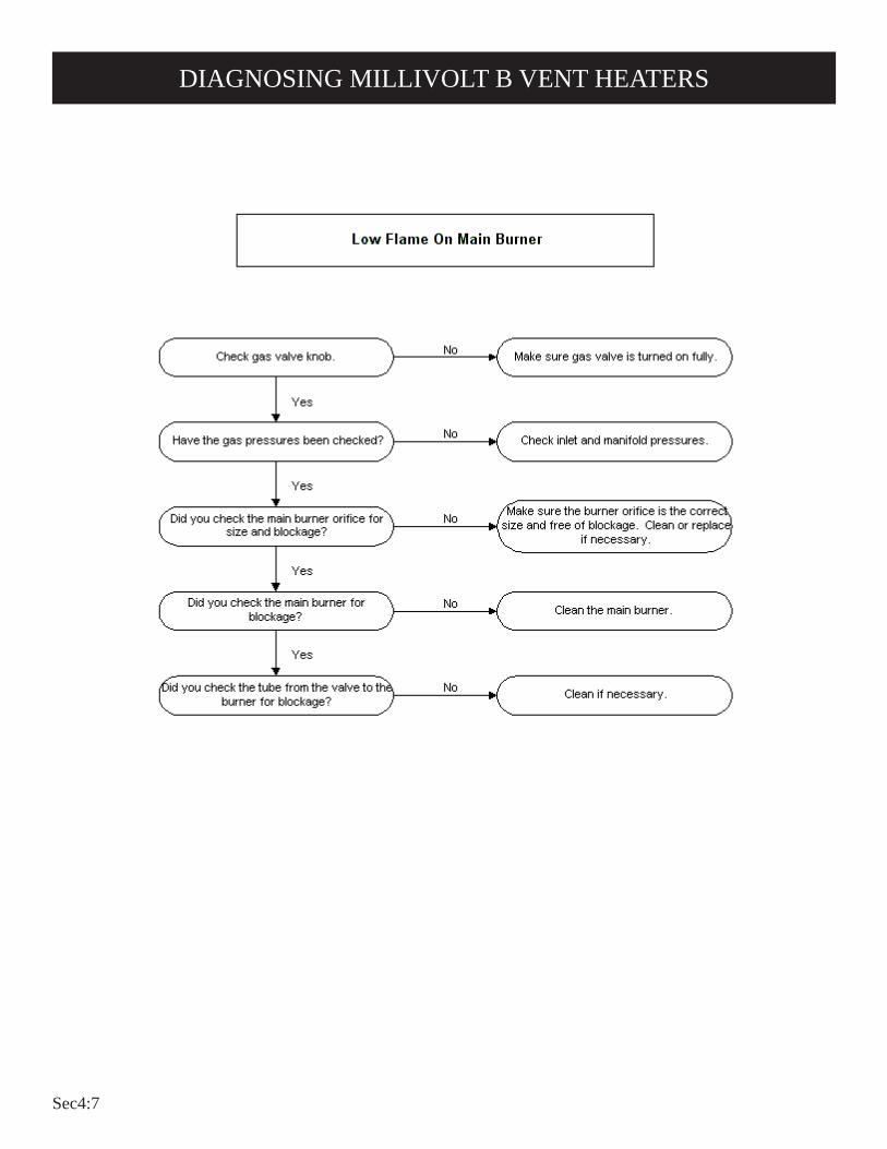
Sec4:7
DIAGNOSING MILLIVOLT B VENT HEATERS

Sec4:8
DIAGNOSING MILLIVOLT B VENT HEATERS

Sec4:9
DIAGNOSING MILLIVOLT B VENT HEATERS

Sec4:10
DIAGNOSING MILLIVOLT B VENT HEATERS

Sec4:11
DIAGNOSING MILLIVOLT B VENT HEATERS

Sec4:12
Sec4:13
GWT Series Heater Troubleshooting

Sec4:14
1. Set the thermostat to lowest setting.2. Turn off all electric power (if applicable) to appliance if
service is to be performed.3. Remove control access panel (control door).
4. Push in gas control knob slightly and turn clockwise to "OFF." Do not force.
5. Replace control access panel (control door).
1. STOP! Read the safety information above.
2. Set the thermostat to lowest setting.
3. Turn off all electric power to the appliance (if appli-cable).
4. Remove control access panel (control door).
5. Push in gas control knob slightly and turn clockwise to "OFF."
NOTE: Knob cannot be turned from "PILOT" to "OFF" unless knob is pushed in slightly. Do not force.
6. Wait ten (10) minutes to clear out any gas. Then smell for gas, including near the floor. If you smell gas, STOP! Follow "B" in the safety information above. If you don't smell gas, go to the next step.
7. Find pilot - follow metal tube from gas control. The pilot is mounted on front of main burner.
8. Turn gas control knob counterclockwise to "PILOT."
9. Push in control knob all the way and hold in. Immedi-ately light the pilot with a match. Continue to hold the control knob in for about one (1) minute after the pilot is lit. Release knob and it will pop back up. Pilot should remain lit. If it goes out, repeat steps 5 through 9.
• If knob does not pop up when released, stop and immediately call a qualified service technician or gas supplier.
• If the pilot will not stay lit after several tries, turn the gas control knob to "OFF" and call your service technician or gas supplier.
10. Turn gas control knob counterclockwise to "ON."
11. Replace control access panel (control door).
12. Turn on all electric power to the appliance (if appli-cable).
13. Set thermostat to desired setting.
GAS CONTROL KNOB SHOWN IN "OFF" POSITION
LIGHTING INSTRUCTIONS
FOR YOUR SAFETY READ BEFORE LIGHTINGWARNING: If you do not follow these instructions exactly, a fire or explosion may result
causing property damage personal injury or loss of life.
A. This appliance has a pilot which must be lighted by hand. When lighting the pilot, follow these instructions exactly.
B. BEFORE LIGHTING smell all around the appliance area for gas. Be sure to smell next to the floor because some gas is heavier than air and will settle on the floor.
WHAT TO DO IF YOU SMELL GAS• Do not try to light any appliance.• Do not touch any electrical switch; do not use any phone in your building.• Immediately call your gas supplier from a neighbor's
phone. Follow the gas supplier's instructions.
• If you cannot reach your gas supplier, call the fire department.
C. Use only your hand to push in or turn the gas control knob. Never use tools. If the knob will not push in or turn by hand, don't try to repair it; call a qualified service technician. Force or attempted repair may result in a fire or explosion.
D. Do not use this appliance if any part has been under water. Immediately call a qualified service technician to inspect the appliance and to replace any part of the control system and any gas control which has been under water.
LIGHTING INSTRUCTIONS
TO TURN OFF GAS TO APPLIANCE

Sec4:15
CAUTION — Do not run wire behind flanges of Header Plate or in any location where it might be damaged. Millivolt wall thermostats are specially designed for use on self-generating systems. They should never be used on line or low voltage A.C. circuits.Interior Wall — The thermostat should be installed on an inside wall away from the furnace but in the same room.
It is important to use wire of a gauge proper for the length of the wire:
RECOMMENDED WIRE GAUGES Maximum Length Wire Gauge 1' to 10' 18 10' to 25' 16 25' to 35' 14
Proper operation depends on a good pilot flame. The flame must cover the top of the thermopile. Cleaning of the pilot orifice and burner may be required due to spiders.System Check (Figure 1)A millivolt meter is required to check the system. Millivolt readings should be:• Across the thermopile terminals, 400-450 millivolts with
thermostat OFF.• Across the thermopile terminals, 150-250 millivolts with
thermostat ON.• Across the thermostat wires at the valve, less than 30 millivolts
with thermostat ON.• Across the thermostat wires at the thermostat, less than 5 millivolts
with thermostat ON. (Dirty pilot or low pressure will reduce readings.)
Connect thermostat wires to gas valve as shown in Figure 1.
Figure 1
THERMOSTAT LOCATION (SG MODELS)
1. In selecting a location for installation, it is necessary to provide adequate accessibility clearances for servicing and proper installation.
2. Clearances to combustible surfaces are 4" (102mm) from sides, 12" (305mm) to top, 1 1/2" (38mm) from floor.
NOTE: Minimum distance of 1 1/2" (38mm) must also be maintained from top surface of carpeting, tile, etc.
CLEARANCES

Sec4:16
Index Part No. Number Description
1 GW-130 Remote Bulb Control Kit 2 R-1224 Remote Bulb Control 3 R-2499 Wire Assembly 4 R-1162 Control Knob 5 R-1720 Plastic Clip (3 Required) 6 R-1223 Instructions 7 R-1578 No. 6-32 x 1/4" (6mm) Screw (2 Required)
Caution: Remote bulb wire routing is important. Wires should be in proper location to avoid damage from being overheated. Incorrect routing of remote bulb control wires may result in damage to wires and incorrect operation of remote bulb control. Follow these instructions and refer to the drawing for proper wire routing.
7. If remote bulb control is located on the right side of the outer casing, carefully bend or loop capillary wire around control. This will enable the sensing bulb to be positioned at the bottom of the unit.
8. Secure sensing bulb on the inside, at the bottom, of the outer casing with (2) plastics clips.
9. Feed the wire assembly down along the inside of the outer casing.10. Use third plastic clip to secure wire assembly and capillary wire to
the casing. (Approximately 24" (610mm) from bottom of unit.)11. Attach control knob to remote bulb control.12. Install furnace according to instructions in the Installation Instructions
and Owner's Manual.Note: If wall furnace is already installed, secure outer casing to unit.13. Attach wire assembly to gas valve at the "TH" and "TH/TP" terminals
on the Robertshaw valve. Attach wire assembly to gas valve at the "THERMO" terminals on
the ITT valve. If the wire assembly has two 1/4" (6mm) female con-nectors, the connectors should be cut off the wire assembly. Strip and bare the wires and attach wires to the "THERMO" terminals. Note: This remote bulb control is connected to the gas valve the same way as a wall thermostat. Any references made to the thermostat in the lighting instructions would also apply to the remote bulb control.
INSTRUCTIONSNote: At the option of the owner, the remote bulb control may be located
on the left or right side of the outer casing.1. Remove remote bulb control from the shipping carton.2. Remove outer casing assembly from shipping carton.
Note: If wall furnace is already installed, remove outer casing from unit and lay on floor with front side down.
3. Attach wire assembly to remote bulb control.4. Carefully unwind capillary wire on remote bulb control.5. Remove (3) hole plugs from left or right side of outer casing where
remote bulb control is to be installed.6. Mount remote bulb control to inside of outer casing with (2) No. 6-32
x 1/4" (6mm) screws.
TO VENT SAFETY
TO REMOTE BULB
TO
TH
ER
MO
PIL
E
MODELSGWT-25 RB, GWT-35 RB, GWT-50 RB
REMOTE BULB CONTROL INSTALLATION INSTRUCTIONS

Sec4:17
This appliance must be properly connected to a venting system. This appliance is equipped with a vent safety shutoff system.
Warning: Operation of this wall furnace when not connected to a properly installed and maintained venting system or tampering with the vent safety shutoff system can result in carbon monoxide (CO) poisoning and possible death.
This furnace is equipped with a manual reset vent safety switch. The manual reset vent safety switch will cause gas flow to the main burner to "shut off" due to improper venting or a blocked flue.To reset the manual reset vent safety switch:1. Remove outer casing.2. Depress manual reset button. The manual reset vent safety
switch is located on the draft diverter.3. Replace outer casing. If the manual reset vent safety switch continues to "shut off" the gas flow to the main burner a qualified service person must be contacted to inspect for improper venting, blockage in the vent pipe or the manual reset vent safety switch for being defective.
Figure 2
The correct flame will be a short blue inner flame with a much larger light blue outer flame. The burner does not have a primary air adjustment. The flame will be proper if the factory-set pressure and orifice are used. After the furnace has begun operating, cleaning of the burner may be needed for proper flame, examine at least 2 times per season.To clean burner ports, disconnect the gas supply to the valve. Remove the burner assembly from the combustion chamber. Remove pilot burner from main burner and then remove the main burner. Force water into the ports and blow dry with vacuum cleaner air, or low pressure compressed air.
The correct flame will be blue, extending past the thermopile. The flame will surround the thermopile just below its tip.Natural gas pilots require adjusting when the inlet gas pressure is above 5" w.c. (1.245kPa). Remove the pilot cover screw on the control valve and turn the adjustment screw clockwise to reduce flame. Replace pilot cover screw to eliminate gas leaking at that control valve opening.LP gas (propane) will not require adjustment.After use, cleaning may be required for the proper flame.Examine the pilot flame before and during each heating season.
Figure 3
Figure 4
VENT SAFETY SHUTOFF SYSTEM
PROPER MAIN BURNER FLAME
PROPER PILOT FLAME

Sec4:18
GENERAL All furnaces have been fire-tested to check for proper operation. This includes main burner flame, pilot flame, and gas control operation. If the furnace fails to function on initial installation, it is advisable to re-check the following:
1. Inlet gas pressure.2. Type of gas being used and that shown on the rating plate.
The Service Department at Empire Comfort Systems, Inc. may be contacted to assist in servicing furnace.Servicing the Pilot and Main Burner, Pilot Orifice, Thermopile and Main Burner Orifice Disconnect the gas supply at the inlet to the control valve. Remove the burner assembly to which the above components are attached.Pilot Does Not Light With air in the gas line, such as when the furnace is first installed or was "OFF" all summer, the pilot flame may be too lean to ignite on the first few trials. Turn the gas control knob to PILOT position and depress the gas control knob. Hold the gas control knob down to bleed the line;
1. Use lighter rod to light pilot with a match.If Pilot Does Not Light By Any Means
1. Check gas control knob for being in the "Pilot" position.2. Check pilot adjustment for being full open (counterclockwise
to open).3. If gas is available in the supply tubing, the pilot orifice and/
or pilot burner is probably restricted by a spider web. Clean pilot assembly and relight.
If Pilot Does Not Remain "On" After Releasing Gas Control Knob
1. Follow instructions and hold gas control knob down longer and harder.
2. Determine if pilot flame extends past thermopile; if not, adjust pilot flame or clean pilot burner.
3. Replace thermopile if millivolt reading is less than 300 millivolts when wall thermostat or remote bulb is turned OFF. Replace gas control if magnet dropout millivolt reading is over 100 millivolts.
Pilot Outage During Normal Operation1. Check input by manifold pressure gauge or gas meter.2. Check millivolt output when furnace is in operation. If
millivolt output decreases during furnace operation gas control may be defective.
Main Gas Valve Does Not Open When Thermostat Is Turned "On"
1. Check millivolt output of thermopile.2. Thermostat wires may be broken.3. Thermostat may be defective.
TROUBLESHOOTING

Sec4:19

Sec4:20

Sec5:1
Thermocouple B Vent Heater Troubleshooting

Sec5:2
DIAGNOSING THERMOCOUPLE B VENT HEATERS

Sec5:3
DIAGNOSING THERMOCOUPLE B VENT HEATERS

Sec5:4
DIAGNOSING THERMOCOUPLE B VENT HEATERS

Sec5:5
DIAGNOSING THERMOCOUPLE B VENT HEATERS

Sec5:6
DIAGNOSING THERMOCOUPLE B VENT HEATERS
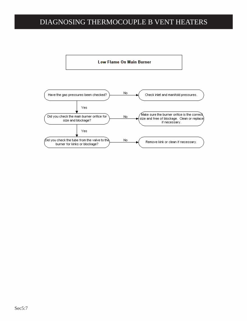
Sec5:7
DIAGNOSING THERMOCOUPLE B VENT HEATERS

Sec5:8
DIAGNOSING THERMOCOUPLE B VENT HEATERS

Sec5:9
DIAGNOSING THERMOCOUPLE B VENT HEATERS
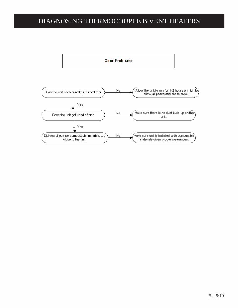
Sec5:10
DIAGNOSING THERMOCOUPLE B VENT HEATERS

Sec5:11
DIAGNOSING THERMOCOUPLE B VENT HEATERS

Sec5:12

Sec5:13
RH Series Heater Troubleshooting
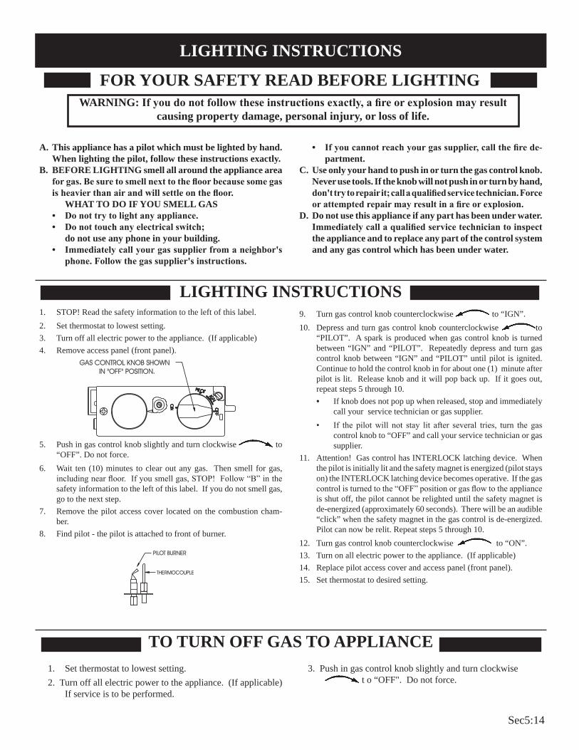
Sec5:14
1. STOP! Read the safety information to the left of this label.2. Set thermostat to lowest setting.3. Turn off all electric power to the appliance. (If applicable)4. Remove access panel (front panel).
5. Push in gas control knob slightly and turn clockwise to “OFF”. Do not force.
6. Wait ten (10) minutes to clear out any gas. Then smell for gas, including near floor. If you smell gas, STOP! Follow “B” in the safety information to the left of this label. If you do not smell gas, go to the next step.
7. Remove the pilot access cover located on the combustion cham-ber.
8. Find pilot - the pilot is attached to front of burner.
9. Turn gas control knob counterclockwise to “IGN”.10. Depress and turn gas control knob counterclockwise to
“PILOT”. A spark is produced when gas control knob is turned between “IGN” and “PILOT”. Repeatedly depress and turn gas control knob between “IGN” and “PILOT” until pilot is ignited. Continue to hold the control knob in for about one (1) minute after pilot is lit. Release knob and it will pop back up. If it goes out, repeat steps 5 through 10.• If knob does not pop up when released, stop and immediately
call your service technician or gas supplier.• If the pilot will not stay lit after several tries, turn the gas
control knob to “OFF” and call your service technician or gas supplier.
11. Attention! Gas control has INTERLOCK latching device. When the pilot is initially lit and the safety magnet is energized (pilot stays on) the INTERLOCK latching device becomes operative. If the gas control is turned to the “OFF” position or gas flow to the appliance is shut off, the pilot cannot be relighted until the safety magnet is de-energized (approximately 60 seconds). There will be an audible “click” when the safety magnet in the gas control is de-energized. Pilot can now be relit. Repeat steps 5 through 10.
12. Turn gas control knob counterclockwise to “ON”.13. Turn on all electric power to the appliance. (If applicable)14. Replace pilot access cover and access panel (front panel).15. Set thermostat to desired setting.
TO TURN OFF GAS TO APPLIANCE
A. This appliance has a pilot which must be lighted by hand. When lighting the pilot, follow these instructions exactly.
B. BEFORE LIGHTING smell all around the appliance area for gas. Be sure to smell next to the floor because some gas is heavier than air and will settle on the floor. WHAT TO DO IF YOU SMELL GAS• Do not try to light any appliance.• Do not touch any electrical switch; do not use any phone in your building.• Immediately call your gas supplier from a neighbor's
phone. Follow the gas supplier's instructions.
• If you cannot reach your gas supplier, call the fire de-partment.
C. Use only your hand to push in or turn the gas control knob. Never use tools. If the knob will not push in or turn by hand, don't try to repair it; call a qualified service technician. Force or attempted repair may result in a fire or explosion.
D. Do not use this appliance if any part has been under water. Immediately call a qualified service technician to inspect the appliance and to replace any part of the control system and any gas control which has been under water.
LIGHTING INSTRUCTIONS
1. Set thermostat to lowest setting.2. Turn off all electric power to the appliance. (If applicable)
If service is to be performed.
3. Push in gas control knob slightly and turn clockwise t o “OFF". Do not force.
FOR YOUR SAFETY READ BEFORE LIGHTINGWARNING: If you do not follow these instructions exactly, a fire or explosion may result
causing property damage, personal injury, or loss of life.
LIGHTING INSTRUCTIONS
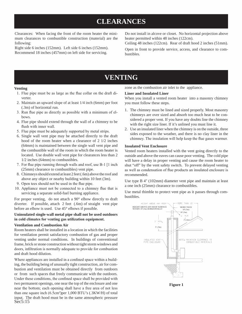
Sec5:15
Clearances: When facing the front of the room heater the mini-mum clearances to combustible construction (material) are the following:Right side 6 inches (152mm). Left side 6 inches (152mm). Recommend 18 inches (457mm) on left side for servicing.
Do not install in alcove or closet. No horizontal projection above heater permitted within 48 inches (122cm). Ceiling 48 inches (122cm). Rear of draft hood 2 inches (51mm). Open in front to provide service, access, and clearance to com-bustibles.
Venting 1. Flue pipe must be as large as the flue collar on the draft di-
verter. 2. Maintain an upward slope of at least 1/4 inch (6mm) per foot
(.3m) of horizontal run. 3. Run flue pipe as directly as possible with a minimum of el-
bows. 4. Flue pipe should extend through the wall of a chimney to be
flush with inner wall. 5. Flue pipe must be adequately supported by metal strips. 6. Single wall vent pipe may be attached directly to the draft
hood of the room heater when a clearance of 2 1/2 inches (64mm) is maintained between the single wall vent pipe and the combustible wall of the room in which the room heater is located. Use double wall vent pipe for clearances less than 2 1/2 inches (64mm) to combustibles.
7. For flue pipe running through walls and roof, use B-1 [1 inch (25mm) clearance to combustibles) vent pipe.
8. Chimneys should extend at least 2 feet (.6m) above the roof and above any object or nearby building within 10 feet (3m).
9. Open tees should not be used in the flue pipe. 10. Appliance must not be connected to a chimney flue that is
servicing a separate solid-fuel burning appliance.For proper venting, do not attach a 90° elbow directly to draft diverter. If possible, attach 2 feet (.6m) of straight vent pipe before an elbow is used. Use 45° elbows if possible.Uninsulated single-wall metal pipe shall not be used outdoors in cold climates for venting gas utilization equipment.Ventilation and Combustion AirRoom heaters shall be installed in a location in which the facilities for ventilation permit satisfactory combustion of gas and proper venting under normal conditions. In buildings of conventional frame, brick or stone construction without tight storm windows and doors, infiltration is normally adequate to provide for combustion and draft hood dilution.Where appliances are installed in a confined space within a build-ing, the building being of unusually tight construction, air for com-bustion and ventilation must be obtained directly from outdoors or from such spaces that freely communicate with the outdoors. Under these conditions, the confined space shall be provided with two permanent openings, one near the top of the enclosure and one near the bottom; each opening shall have a free area of not less than one square inch (6.5cm2)per 1,000 BTU’s (.3KW/H) of total input. The draft hood must be in the same atmospheric pressure
zone as the combustion air inlet to the appliance.Liner and Insulated LinerWhen you install a vented room heater into a masonry chimney you must follow these steps.
1. The chimney must be lined and sized properly. Most masonry chimneys are over sized and absorb too much heat to be con-sidered a proper vent. If you have any doubts line the chimney with the right size liner. If it’s unlined you must line it.
2. Use an insulated liner when the chimney is on the outside, three sides exposed to the weather, and there is no clay liner in the chimney. The insulation will help keep the flue gases warmer.
Insulated Vent EnclosureVented room heaters installed with the vent going directly to the outside and above the eaves can cause poor venting. The cold pipe will have a delay in proper venting and cause the room heater to shut “off” by the vent safety switch. To prevent delayed venting as well as condensation of flue products an insulated enclosure is recommended.Use type B 4" (102mm) diameter vent pipe and maintain at least a one inch (25mm) clearance to combustibles.Use metal thimble to protect vent pipe as it passes through com-bustibles.
Figure 1
MORE THAN 10' (3m)
10' (3m)
2' (.6m)
HEIGHT ABOVE ANY ROOF SURFACE WITHIN 10' (3m) HORIzONTALLY
3' (.9m)
VENTING
CLEARANCES

Sec5:16
The correct flame will be almost horizontal, blue and will extend past the thermocouple 1/4" (6mm). The flame will surround the thermocouple just below the tip.On Propane (LP-gas) slight yellow might occur where the pilot flame and the burner flame meet.Natural gas pilots require adjusting when the inlet pressure is above 5" w.c. (1.25kPa) Remove pilot adjustment cover. Turn adjust-ment screw clockwise to reduce flame.Propane (LP-gas) will not require adjusting.After use, cleaning of the pilot burner may be required for the proper flame. The pilot orifice can be cleaned with high pressure air or by placing under running water. Pilot orifice must be dry before replacement. Use a pipe cleaner to clean inside the pilot after the pilot orifice has been removed.To Remove Pilot Orifice1. Disconnect the pilot supply line at the pilot burner.2. Remove pilot orifice from pilot burner.It may be necessary to
tap on pilot burner in order to remove the pilot orifice.
Figure 2
There will be a short blue inner flame with a larger, lighter blue secondary flame. The burner flame may have yellow tips when hot. Dust in the combustion air will produce an orange or red flame. Do not mistake the orange or red flame for an improper yellow flame.Attention: On Propane gas, if a whistling noise (resonation) occurs close the air shutter on the main burner in order to reduce the amount of primary air. The reduction in primary air will soften the main burner flame and will eliminate the whistling noise (resonation). On Propane or Natural gas if a yellow flame occurs open the air shutter on the main burner in order to increase the amount of primary air. The increase in primary air will sharpen the main burner and will eliminate the yellow flame.
After use, cleaning of the main burner may be required for the proper flame. The main burner may be cleaned by forcing water into the ports and the throat of the burner. The burner should be blown dry or heated to remove all water before replacement.
Figure 3
On Propane Gas, if a whistling noise (resonation) occurs a. Close the air shutter on the main burner in order to reduce
the amount of primary air.
MAIN BURNER FLAME CHARACTERISTICS
PILOT FLAME CHARACTERISTICS

Sec5:17
To Remove Main Burner1. Disconnect the thermocouple and pilot supply line at the pilot
burner.2. Unscrew the nut on the orifice fitting union. Orifice fitting is
threaded into the main burner.3. Remove screw on each side of the main burner and lift out.
To Remove Main Burner Orifice1. Unscrew the nut on the orifice fitting union. Orifice fitting is
threaded into the main burner.2. Unthread the orifice fitting from the main burner.3. Main burner orifice is located at the end of the orifice fit-
ting.4. Remove main burner orifice from orifice fitting with a 1/2"
(13mm) wrench.
Cleaning Combustion ChamberA qualified serviceman should remove the chamber and apply air pressure to the inside in order to clear all passageways.
1. Impossible to light pilota. If using piezo ignitor, check electrode location.b. Remove nut at orifice and check for gas.c. If gas available, check for blocked orifice or pilot.
2. Pilot outage a. Proper size of pilot flame.b. Defective or weak thermocouple.
3. Pilot flames but goes out when knob is releaseda. Pilot flame not covering the thermocouple properly.b. Defective thermocouple.c. Defective magnet in the safety section of valve.
4. Poor thermostat controla. Thermostat needs calibrating.b. Defective thermostat section.
5. Noisy blower a. Tighten blower screws.b. Check blower wheel in the open for balance.
6. Yellow main burner flame a. Remove main burner to check for obstructions in throat,
ports and orifices.b. Install new main burner orifice and pilot orifice.c. Check gas valve for leaking.d. Open the air shutter on the main burner in order to increase
the amount of primary air.
7. Yellow pilot flamea. Small yellow tip not objectionable.b. Remove pilot orifice. Check and clean.
8. Pilot and main burner goes out after burning a few min-utesa. Improper venting of flue products. Relight and check for
improper venting.b. If vented properly, check vent safety switch, replace if
defective. 9. Burner flashes- back or “pops” and burns at main burner
orificea. Examine main burner for defects.
10. Inoperative blower a. Check fan control by shorting across terminals.b. Check for blower wheel bind by removing wheel and
operating motor.c. Check for frozen bearings due to lack of oil.
TROUBLESHOOTING
MAINTENANCE

Sec5:18
SERVICE NOTES

Sec5:19
SERVICE NOTES

Sec5:20

Sec6:1
24 Volt B Vent Heater Troubleshooting

Sec6:2
DIAGNOSING 24 VOLT B VENT HEATERS

Sec6:3
DIAGNOSING 24 VOLT B VENT HEATERS

Sec6:4
DIAGNOSING 24 VOLT B VENT HEATERS

Sec6:5
DIAGNOSING 24 VOLT B VENT HEATERS

Sec6:6
DIAGNOSING 24 VOLT B VENT HEATERS

Sec6:7
DIAGNOSING 24 VOLT B VENT HEATERS

Sec6:8
DIAGNOSING 24 VOLT B VENT HEATERS
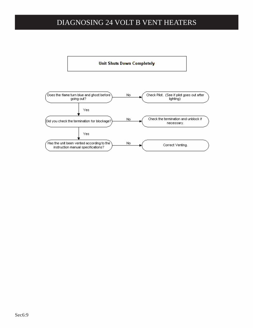
Sec6:9
DIAGNOSING 24 VOLT B VENT HEATERS

Sec6:10
DIAGNOSING 24 VOLT B VENT HEATERS

Sec6:11
DIAGNOSING 24 VOLT B VENT HEATERS

Sec6:12

Sec6:13
FAW Series Heater Troubleshooting

Sec6:14
FAW-40-SPP and IP Series Heater Troubleshooting

Sec6:15
FOR YOUR SAFETY READ BEFORE LIGHTINGWARNING: If you do not follow these instructions exactly, a fire or explosion may result
causing property damage, personal injury or loss of life.
A. This appliance has a pilot which must be lighted by hand. When lighting the pilot, follow these instructions exactly.
B. BEFORE LIGHTING smell all around the appliance area for gas. Be sure to smell next to the floor because some gas is heavier than air and will settle on the floor.
WHAT TO DO IF YOU SMELL GAS• Do not try to light any appliance.• Do not touch any electrical switch; do not use any phone in your building.• Immediately call your gas supplier from a neighbor's
phone. Follow the gas supplier's instructions.• If you cannot reach your gas supplier, call the fire
department.
C. Use only your hand to push in or turn the gas control knob. Never use tools. If the knob will not push in or turn by hand, don't try to repair it; call a qualified service technician. Force or attempted repair may result in a fire or explosion.
D. Do not use this appliance if any part has been under water. Immediately call a qualified service technician to inspect the appliance and to replace any part of the control system and any gas control which has been under water.
TO TURN OFF GAS TO APPLIANCE 1. Set the thermostat to lowest setting.
2. Turn off all electric power to appliance if service is to be performed .
3. Remove control access panel (lower front panel).
4. Push in gas control knob slightly and turn clockwise to "OFF." Do not force.
5. Replace control access panel (lower front panel).
LIGHTING INSTRUCTIONS 1. STOP! Read the safety information above. 2. Set the thermostat to lowest setting. 3. Turn off all electric power to the appliance. 4. Remove control access panel (lower front panel). 5. Turn gas control knob clockwise to "OFF."
6. Wait ten (10) minutes to clear out any gas. Then smell
for gas, including near the floor. If you smell gas, STOP! Follow "B" in the safety information above. If you don't smell gas, go to the next step.
7. Remove the pilot access cover located on the combustion chamber.
8. Find pilot - follow metal tube from gas control. The pilot is located between the two burner tubes behind the pilot access cover. 9. Turn gas control knob counterclockwise to "PILOT."
10. Push and hold red reset button down completely and repeatedly push the ignitor button until the pilot burner is lit. Pilot may also be lit with a match. Continue to hold the red reset button down for about one (1) minute after the pilot is lit. Release button and it will pop back up. Pilot should remain lit. If it goes out, repeat steps 5 through 10.
• If button does not pop up when released, stop and immediately call a qualified service technician or gas supplier.
• If the pilot will not stay lit after several tries, turn the gas control knob to "OFF" and call your service technician or gas supplier.
11. Replace pilot access cover. 12. Turn gas control knob counterclockwise
to "ON." 13. Replace control access panel (lower front panel). 14. Turn on all electric power to the appliance. 15. Set thermostat to desired setting.
STANDING PILOT MODEL
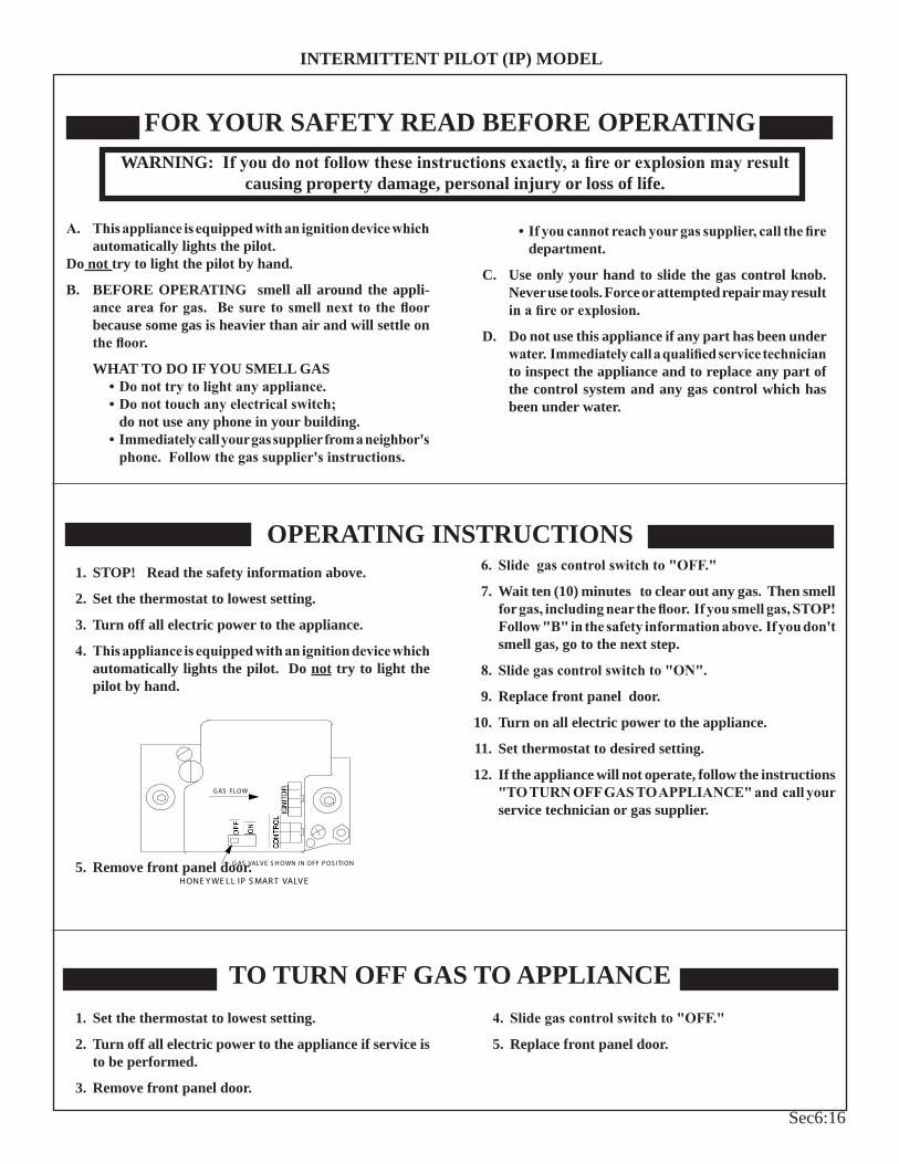
Sec6:16
FOR YOUR SAFETY READ BEFORE OPERATINGWARNING: If you do not follow these instructions exactly, a fire or explosion may result
causing property damage, personal injury or loss of life.
A. This appliance is equipped with an ignition device which automatically lights the pilot.
Do not try to light the pilot by hand.
B. BEFORE OPERATING smell all around the appli-ance area for gas. Be sure to smell next to the floor because some gas is heavier than air and will settle on the floor.
WHAT TO DO IF YOU SMELL GAS• Do not try to light any appliance.• Do not touch any electrical switch; do not use any phone in your building.• Immediately call your gas supplier from a neighbor's
phone. Follow the gas supplier's instructions.
• If you cannot reach your gas supplier, call the fire department.
C. Use only your hand to slide the gas control knob. Never use tools. Force or attempted repair may result in a fire or explosion.
D. Do not use this appliance if any part has been under water. Immediately call a qualified service technician to inspect the appliance and to replace any part of the control system and any gas control which has been under water.
1. STOP! Read the safety information above.
2. Set the thermostat to lowest setting.
3. Turn off all electric power to the appliance.
4. This appliance is equipped with an ignition device which automatically lights the pilot. Do not try to light the pilot by hand.
ONOF F
IG NITOR
CON TR OL
G AS FLOW
G AS VALV E S H OWN IN OFF P OS ITION
HONE Y WE L L IP S MAR T VALV E 5. Remove front panel door.
6. Slide gas control switch to "OFF."
7. Wait ten (10) minutes to clear out any gas. Then smell for gas, including near the floor. If you smell gas, STOP! Follow "B" in the safety information above. If you don't smell gas, go to the next step.
8. Slide gas control switch to "ON".
9. Replace front panel door.
10. Turn on all electric power to the appliance.
11. Set thermostat to desired setting.
12. If the appliance will not operate, follow the instructions "TO TURN OFF GAS TO APPLIANCE" and call your service technician or gas supplier.
OPERATING INSTRUCTIONS
TO TURN OFF GAS TO APPLIANCE 1. Set the thermostat to lowest setting.
2. Turn off all electric power to the appliance if service is to be performed.
3. Remove front panel door.
4. Slide gas control switch to "OFF."
5. Replace front panel door.
INTERMITTENT PILOT (IP) MODEL
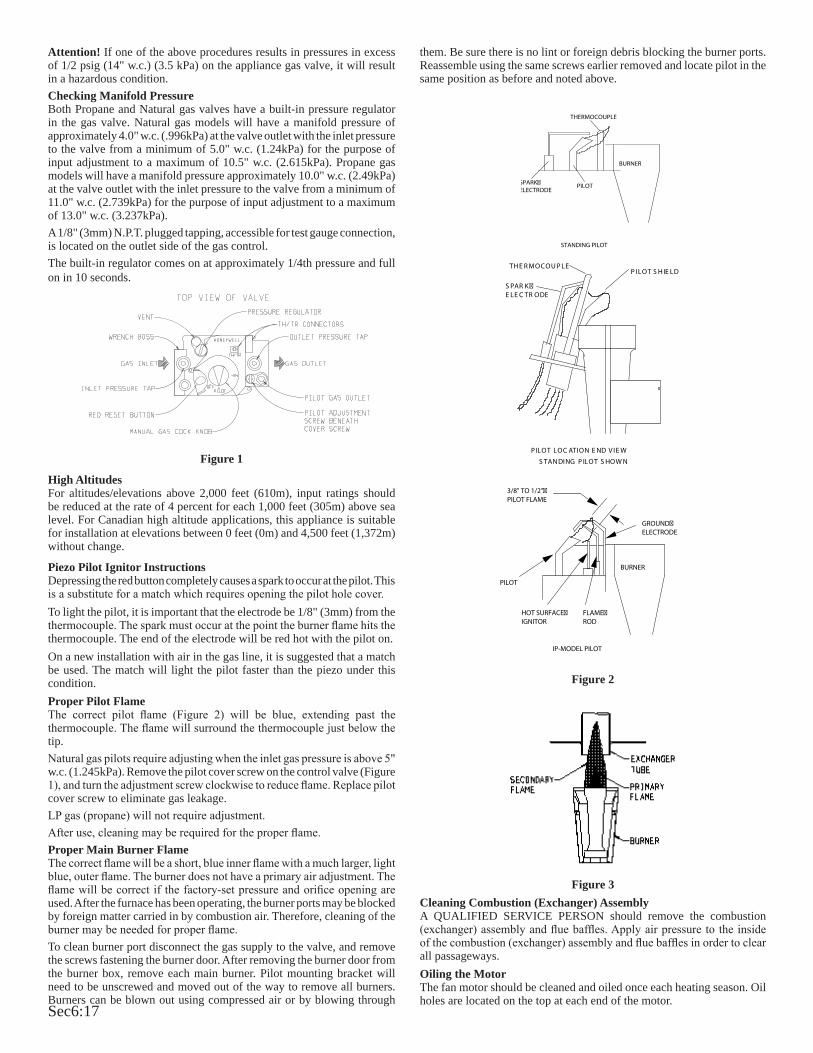
Sec6:17
Attention! If one of the above procedures results in pressures in excess of 1/2 psig (14" w.c.) (3.5 kPa) on the appliance gas valve, it will result in a hazardous condition.Checking Manifold PressureBoth Propane and Natural gas valves have a built-in pressure regulator in the gas valve. Natural gas models will have a manifold pressure of approximately 4.0" w.c. (.996kPa) at the valve outlet with the inlet pressure to the valve from a minimum of 5.0" w.c. (1.24kPa) for the purpose of input adjustment to a maximum of 10.5" w.c. (2.615kPa). Propane gas models will have a manifold pressure approximately 10.0" w.c. (2.49kPa) at the valve outlet with the inlet pressure to the valve from a minimum of 11.0" w.c. (2.739kPa) for the purpose of input adjustment to a maximum of 13.0" w.c. (3.237kPa). A 1/8" (3mm) N.P.T. plugged tapping, accessible for test gauge connection, is located on the outlet side of the gas control.The built-in regulator comes on at approximately 1/4th pressure and full on in 10 seconds.
Figure 1
High AltitudesFor altitudes/elevations above 2,000 feet (610m), input ratings should be reduced at the rate of 4 percent for each 1,000 feet (305m) above sea level. For Canadian high altitude applications, this appliance is suitable for installation at elevations between 0 feet (0m) and 4,500 feet (1,372m) without change.
Piezo Pilot Ignitor InstructionsDepressing the red button completely causes a spark to occur at the pilot. This is a substitute for a match which requires opening the pilot hole cover.To light the pilot, it is important that the electrode be 1/8" (3mm) from the thermocouple. The spark must occur at the point the burner flame hits the thermocouple. The end of the electrode will be red hot with the pilot on.On a new installation with air in the gas line, it is suggested that a match be used. The match will light the pilot faster than the piezo under this condition. Proper Pilot FlameThe correct pilot flame (Figure 2) will be blue, extending past the thermocouple. The flame will surround the thermocouple just below the tip.Natural gas pilots require adjusting when the inlet gas pressure is above 5" w.c. (1.245kPa). Remove the pilot cover screw on the control valve (Figure 1), and turn the adjustment screw clockwise to reduce flame. Replace pilot cover screw to eliminate gas leakage.LP gas (propane) will not require adjustment.After use, cleaning may be required for the proper flame.Proper Main Burner FlameThe correct flame will be a short, blue inner flame with a much larger, light blue, outer flame. The burner does not have a primary air adjustment. The flame will be correct if the factory-set pressure and orifice opening are used. After the furnace has been operating, the burner ports may be blocked by foreign matter carried in by combustion air. Therefore, cleaning of the burner may be needed for proper flame.To clean burner port disconnect the gas supply to the valve, and remove the screws fastening the burner door. After removing the burner door from the burner box, remove each main burner. Pilot mounting bracket will need to be unscrewed and moved out of the way to remove all burners. Burners can be blown out using compressed air or by blowing through
them. Be sure there is no lint or foreign debris blocking the burner ports. Reassemble using the same screws earlier removed and locate pilot in the same position as before and noted above.
SPARK�ELECTRODE
THERMOCOUPLE
PILOT
BURNER
STANDING PILOT
P ILOT LOC ATION E ND V IE W
P ILOT S H IE LDTH E R MOCOU P LE
S PAR K �E LE C TR ODE
S TAN DING P ILOT S HOW N
BURNER
PILOT
HOT SURFACE�IGNITOR
FLAME�ROD
GROUND�ELECTRODE
3/8" TO 1/2"�PILOT FLAME
IP-MODEL PILOT
Figure 2
Figure 3Cleaning Combustion (Exchanger) AssemblyA QUALIFIED SERVICE PERSON should remove the combustion (exchanger) assembly and flue baffles. Apply air pressure to the inside of the combustion (exchanger) assembly and flue baffles in order to clear all passageways.Oiling the MotorThe fan motor should be cleaned and oiled once each heating season. Oil holes are located on the top at each end of the motor.
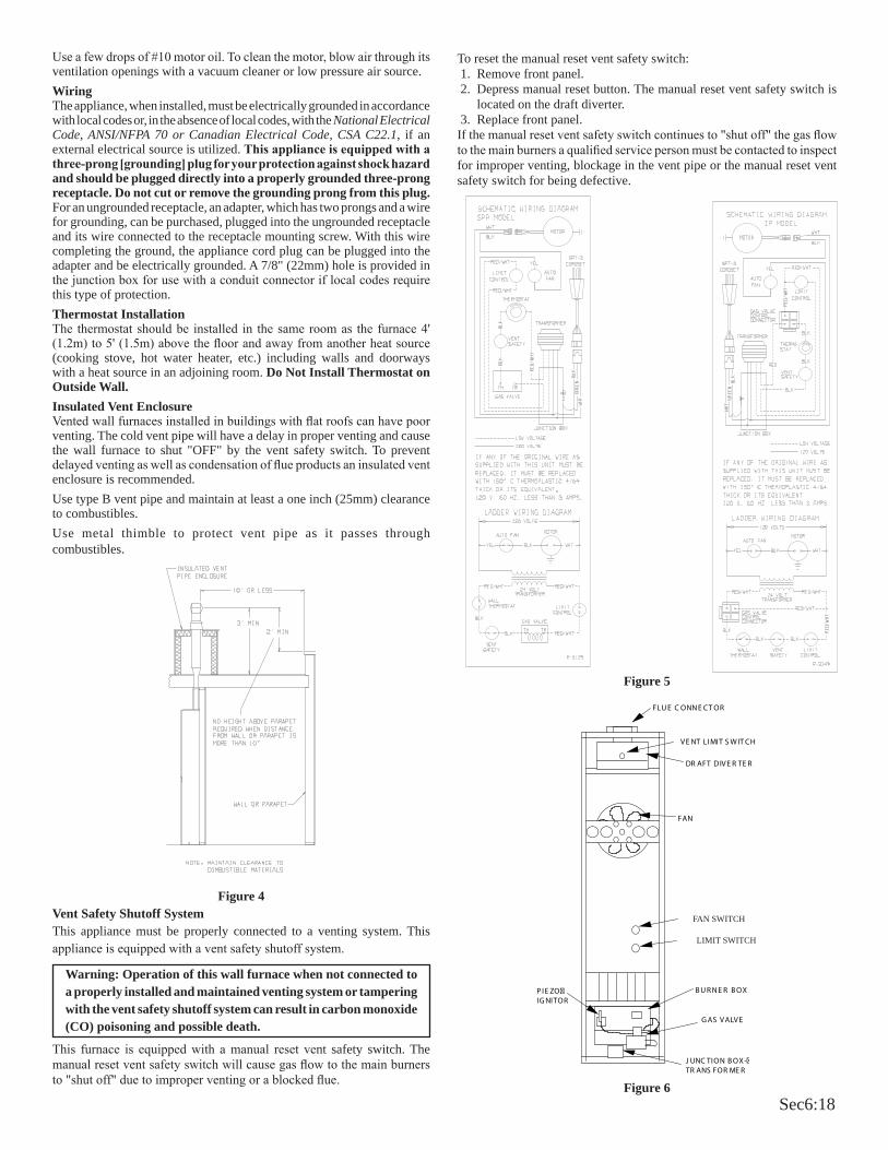
Sec6:18
Use a few drops of #10 motor oil. To clean the motor, blow air through its ventilation openings with a vacuum cleaner or low pressure air source.WiringThe appliance, when installed, must be electrically grounded in accordance with local codes or, in the absence of local codes, with the National Electrical Code, ANSI/NFPA 70 or Canadian Electrical Code, CSA C22.1, if an external electrical source is utilized. This appliance is equipped with a three-prong [grounding] plug for your protection against shock hazard and should be plugged directly into a properly grounded three-prong receptacle. Do not cut or remove the grounding prong from this plug. For an ungrounded receptacle, an adapter, which has two prongs and a wire for grounding, can be purchased, plugged into the ungrounded receptacle and its wire connected to the receptacle mounting screw. With this wire completing the ground, the appliance cord plug can be plugged into the adapter and be electrically grounded. A 7/8" (22mm) hole is provided in the junction box for use with a conduit connector if local codes require this type of protection.Thermostat InstallationThe thermostat should be installed in the same room as the furnace 4' (1.2m) to 5' (1.5m) above the floor and away from another heat source (cooking stove, hot water heater, etc.) including walls and doorways with a heat source in an adjoining room. Do Not Install Thermostat on Outside Wall.Insulated Vent EnclosureVented wall furnaces installed in buildings with flat roofs can have poor venting. The cold vent pipe will have a delay in proper venting and cause the wall furnace to shut "OFF" by the vent safety switch. To prevent delayed venting as well as condensation of flue products an insulated vent enclosure is recommended.Use type B vent pipe and maintain at least a one inch (25mm) clearance to combustibles.Use metal thimble to protect vent pipe as it passes through combustibles.
Figure 4Vent Safety Shutoff SystemThis appliance must be properly connected to a venting system. This appliance is equipped with a vent safety shutoff system.
Warning: Operation of this wall furnace when not connected to a properly installed and maintained venting system or tampering with the vent safety shutoff system can result in carbon monoxide (CO) poisoning and possible death.
This furnace is equipped with a manual reset vent safety switch. The manual reset vent safety switch will cause gas flow to the main burners to "shut off" due to improper venting or a blocked flue.
To reset the manual reset vent safety switch: 1. Remove front panel. 2. Depress manual reset button. The manual reset vent safety switch is
located on the draft diverter. 3. Replace front panel.If the manual reset vent safety switch continues to "shut off" the gas flow to the main burners a qualified service person must be contacted to inspect for improper venting, blockage in the vent pipe or the manual reset vent safety switch for being defective.
Figure 5
B U R N E R B OX
G AS V ALV E
J UNC TION B OX-�TR ANS FOR ME R
LIMIT S WITC H
FAN S WITC H
V E NT LIMIT S W IT CH
FLU E C ONN E CT OR
FAN
P IE ZO�IG NITOR
DR AFT D IV E R TE R
Figure 6
FAN SWITCH
LIMIT SWITCH

Sec6:19
SERVICE AND MAINTENANCE SUGGESTIONSCALL SERVICEMAN
GENERAL: All furnaces have been fire-tested to check for proper operation. This includes, main burner flame, pilot flame, fan operation, fan control, limit control and automatic valve operation. If the furnace fails to function on initial installation, it is advisable to re-check the following:
1. 115 volts to the junction box.2. Inlet gas pressure.3. The 24 volt system.4. Type of gas being used and that shown on the rating label.
The Service Department at Empire Comfort Systems, Inc. may be contacted to assist in servicing furnace.Standing Pilot ModelServicing the Pilot and Main Burners, Pilot Orifice, Thermocouple, and Main Burner Orifices: Disconnect the gas supply at the inlet to the control valve. Then remove the burner door to gain access to the above listed components.Spark Igniter Does Not Light Pilot: With air in the gas line, such as when the furnace is first installed or was off all summer, the pilot flame may be too lean to ignite on the first few trials. Turn the control valve knob to pilot position and depress the red reset button. Holding the button down continually to bleed the line;.
1. Use lighter rod to light pilot with a match.2. Use the piezo ignitor at 30 second intervals until it lights.
If Electrode Does Not Produce Spark:1. Check wire connections.2. Check gap for pilot burner to the electrode tip. Should be between
1/8" (3mm) and 3/16" (5mm). Electrode wire and tip must be more than 1/4" (6mm) away from all other metal components.
If Pilot Does Not Light By Any Means:1. Check valve knob for being in the "Pilot" position.2. Check pilot adjustment for being full open (counterclockwise to
open).3. If gas is available in the supply tubing, the pilot orifice and/or pilot
burner is probably restricted by a spider web. Clean pilot assembly and relight.
If Pilot Does Not Remain On After Releasing Knob: 1. Follow instructions and hold button down longer and harder.2. Determine if pilot flame extends past thermocouple; if not, adjust
input or clean pilot burner.3. Replace thermocouple if millivolts read less than 15 millivolts.
Main Gas Valve Does Not Open When Thermostat Is Turned To On:1. Check for 24 volts to valve by removing one wire and touching to the
SAME TERMINAL it was on. Terminal should have a light spark. DO NOT SHORT ACROSS TERMINALS, AS IT WILL BURN OUT THE WALL THERMOSTAT.
2. Thermostat wires at the wall may be shorted, so check for a faulty thermostat.
3. To check for line voltage to furnace, remove front panel and short across two-terminal fan control to allow fan to operate (Figure 6).
CAUTION: Label all wires prior to disconnection when servicing controls. Wiring errors can cause improper and dangerous operation. Verify proper operation after servicing.
IP-Model PilotThis heater is using a Honeywell "Smart Valve" system for intermittent pilot ignition.On a call for heat by the thermostat this control turns on a 24 volt mini hot surface ignitor which lights a pilot that in turn lights the main burner. The gas valve used in this system is a step opening which opens at a lower pressure for ignition and then steps to a full inlet pressure of 4" H2O pressure on Natural gas and 10" H20 pressure on LP gas.
Pilot Flame AdjustmentThe pilot flame should envelop 3/8 to 1/2 inch (10 to 13mm) of the tip of the flame rod. See Figure 2.To adjust:
1. Remove the pilot adjustment cover screw.2. Turn the inner adjustment screw clockwise to decrease or
counterclockwise to increase pilot flame. Pilot adjustment is shipped at full flow rate. Turn the inner adjustment screw clockwise
if the inlet pressure is too high.3. Replace the cover screw after the adjustment to prevent gas leak-
age.
ONOFF
IG N IT OR
C ONT R OL
INLE T P R E S S U R E TAP
OU TLE T P R E S S UR E TAP
P ILOT ADJ US T ME N T-�U ND E R CAP S C R E W
P ILOT OUT LE T
P R E S S U R E R E G U LAT OR �ADJ US T ME N T-UN DE R C AP �S CR E W
G AS F LOW
IG NITOR
C ONT R OL
TO 24 V. TH E R MOS TAT
T O 24 V. COMMON ON T R AN S FOR ME RTO 24 V ."H OT" ON TR ANS F OR ME R
WIR IN G
I P-MO DE L G AS VALV E AN D WIR ING
IG N IT OR -P ILOT AS S Y.
FAN�SWITCH
MOTOR
HONEYWELL IP�SMART VALVE
120 VAC
LIMIT�CONTROL
VENT SAFETY�LIMIT
THERMOSTAT
40 VA TRANSFORMER
24 VAC
120VAC
VALVE CONTROL�CONNECTOR
L1 "HOT"L2 NEUTRAL
LADDER WIRING DIAGRAM-IP VALVE
Figure 7

Sec6:20
START
System Check
Trial forIgnition
Main BurnerOperation
END
Pilot Valve OpensIgnitor Powered
Flame SignalDetected
ThermostatCalls for Heat
Ignitor OFFMain Valve Opens
Internal CheckOK
Pilot Light and Flame isSensed During Trial For
Ignition (1)
Apply 24 VACTo Appliance
Main Pilot ValvesClose
Thermostat Call for HeatEnds
Flame SignalLost?
Pilot Valve Ignition OFFWait for Flame Signal to
Disappear
Pilot Valve ClosesIgnition OFF
Main PilotValves Close
Flame Lost MoreThan 5 Times inOne Call for Heat
5 Minute Retry Delay
3 Second Flame RecycleDelay
YES
NO
NO
YES
NO
YES
YES
NO
YES
NO
(1) Ignitor will turn OFF about 30 seconds into the trial for ignition if the pilot flame has not lit. It will turn back ON for the final 30 secondsof the 90 second trial for ignition. The pilot valve will be energized during the entire trial for ignition. This is normal operation for this gasignition system.
SEQUENCE OF OPERATION

Sec6:21
START IP SYSTEM TROUBLESHOOTING SEQUENCE
TurnOFFGasSupplyDisconnect System ControlHarnessSet Thermostat to Call forHeat
Check for Proper Voltage atControl Harness (See InsetA -Voltage Should be 24VBetween Thermostat and 24VCommon, and 24V Between24VCommonand24VHot.)
Plug Harness into SmartValveControlWait for Internal Check Delay(SV9501)
IgniterWarms UP and GlowsRed
Note: Igniter Will Cycle OFFand Back ONOnce During the90Second IgnitionTrial
TurnOnGasSupplyPilotBurnerLights
MainValveOpens andMainBurnerLights
System isOkay
CheckLine Voltage PowerLow Voltage TransformerLimit ControllerThermostatWiring
Unplug Pilot Burner Cable.Measure Voltage at SmartValue HSIElement Output (See Inset B) 24VNominal
Replace Igniter/Flame RodAssembly
Reconnect Pilot Burner Cable
Check that Pilot Gas is FlowingWait to Assure Pilot Gas Tubing isPurged.
Measure Voltage Between 24V Hotand 24V Common Leads toSmartValve Control. Must Measureat Least 19.5 VAC with IgniterPowered. See Inset A to IdentifyProper Lead. This Check Must beDone with the SmartValve ControlConnected and Igniter Powered.
Replace Igniter/Flame RodAssembly
Check that Pilot Flame MakesGood Contact with Pilot BurnerFlame RodCheck for Good ElectricalConnection Through the PilotTubingIf Both of the Above are Good,Replace Igniter/Flame Rod
Cycle Thermostat OFF and BackON
Main Burner Lights
YES
NO
NO
NO
NO
YES
YES
YES
Replace SmartValve Control
Reconnect Pilot Burner Cable
NO
Replace SmartValve ControlNO
Check Transformer and Line VoltSupply
NO
Replace SmartValve ControlNO
SmartValve System Troubleshooting SequenceNote: Before Troubleshooting, Become Familiar
with the Sequence of Operation
TM
HSITerminals
INSET B
End Viewof ControlHarnessConnector
EFTOutput
24 VoltHot
24Volts
24 VoltCommon
24Volts
24 VoltThermostat
INSET A

Sec6:22
FAW-55SPP Series Heater Troubleshooting

Sec6:23
FOR YOUR SAFETY READ BEFORE LIGHTING
WARNING: If you do not follow these instructions exactly, a fire or explosion may result causing property damage, personal injury or loss of life.
A. This appliance has a pilot which must be lighted by hand. When lighting the pilot, follow these instructions exactly.
B. BEFORE LIGHTING smell all around the appliance area for gas. Be sure to smell next to the floor because some gas is heavier than air and will settle on the floor.
WHAT TO DO IF YOU SMELL GAS •Do not try to light any appliance. •Do not touch any electrical switch; do not use any phone in your building. •Immediately call your gas supplier from a neighbor’s
phone, Follow the gas supplier’s instructions.
•If you cannot reach your gas supplier, call the fire department.
C. Use only your hand to push in or turn the gas control knob. Never use tools. If the knob will not push in or turn by hand, don’t try to repair it; call a qualified service technician. Force or attempted repair may result in a fire or explosion.
D. Do not use this appliance if any part has been under water. Immediately call a qualified service technician to inspect the appliance and to replace any part of the control system and any gas control which has been under water.
LIGHTING INSTRUCTIONS1. STOP! Read safety information above.2. Set the thermostat to lowest setting.3. Turn off all electric power to the appliance.4. Remove control access panel (lower front panel).5. Turn gas control knob clockwise to “OFF.”
6. Wait ten (10) minutes to clear out any gas. Then smell for gas, including near the floor. If you smell gas, STOP! Fol-low “B” in the safety information above. If you don’t smell gas, go to the next step.
7. Remove the pilot access cover located on the combustion chamber.
8. Find pilot - follow metal tube from gas control. The pilot is located between the two burner tubes behind the pilot access cover.
9. Turn gas control knob counterclockwise to “Pilot.”
10. Push and hold red reset button down completely and repeatedly push the ignitor button until the pilot burner is lit. Pilot may also be lit with a match. Continue to hold the red rest button down for about one (1) minute after the pilot is lit. Release button and it will pop back up. Pilot should remain lit. If it goes out, repeat step 5 through 10.
• If button does not pup up when released, stop and immediately call a qualified service technician or gas supplier.
• If the pilot will not stay lit after several tries, turn the gas control knob to “OFF” and call your service technician or gas supplier.
11. Replace pilot access cover.12. Turn gas control knob counterclockwise
to “ON.”13. Replace control access panel (lower front panel).14. Turn on all electric power to the appliance.15. Set thermostat to desired setting.
GAS CONTROL KNOB SHOWN
IN “OFF” POSITION.
THERMOCOUPLEPILOT BURNER
TO TURN OFF GAS TO APPLIANCE1. Set the thermostat to lowest setting.2. Turn off all electric power to appliance if service is to be
performed.3. Remove control access panel (lower front panel).
4. Push in gas control knob slightly and turn clockwise to “OFF.” Do not force.
5. Replace control access panel (lower front panel).

Sec6:24
WiringThe appliance, when installed, must be electrically grounded in accor-dance with local codes or, in the absence of local codes with the National Electrical Code, ANSI/NFPA70 or Canadian Electrical Code CSA C22.1, if an external electrical source is utilized. This appliance is equipped with a three-prong (grounding) plug for your protection against shock hazard and should be plugged directly into a properly ground-ed three-prong receptacle. Do not cut or remove the grounding prong from this plug. For an ungrounded receptacle, an adapter, which has two prongs and a wire for grounding, can be purchased, plugged into the ungrounded receptacle and its wire connected to the receptacle mounting screw. With this wire completing the ground, the appliance cord plug can be plugged into the adapter and be electrically grounded. A 7/8” (22mm) hole is provided in the junction box for use with a conduit connector if local codes require this type of protection.
Thermostat InstallationThe thermostat should be installed in the same room as the furnace 4’ (1.2m) to 5’ (1.5m) above the floor and away from another heat source (cooking stove, hot water heater, etc.) including walls and doorways with a heat source in an adjoining room. Do Not Install Thermostat on Out-side Wall.
On a new installation with air in the gas line, it is suggested that a match be used. The match will light the pilot faster than the piezo under this condition.
Proper Pilot FlameThe correct pilot flame (Figure 1) will be blue, extending past the thermo-couple. The flame will surround the thermocouple just below the tip.
Natural gas pilots require adjusting when the inlet gas pressure is above 5” w.c. (1.245kPa). Remove the pilot cover screw on the control valve (Figure 5), and turn the adjustment screw clockwise to reduce flame. Re-place pilot cover screw to eliminate gas leakage.
LP gas (propane) will not require adjustment.
After use, cleaning may be required for the proper flame.
PROPER FLAME ADJUSTMENT
Figure 1
Proper Main Burner FlameThe correct flame will be a short blue inner flame with a much larger light blue outer flame. The main burner (Figure 7) shows the approximate height of each part of the flame for each gas. The burner does not have a primary air adjustment. The flame will be correct if the factory-set pres-sure and orifice opening are used. After the furnace has been operating, the burner ports may be blocked by foreign matter carried in by com-bustion air. Therefore, cleaning of the burner may be needed for proper flame.To clean burner port disconnect the gas supply to the valve, and remove the eight screws fastening the burner door. After removing the burner door from the combustion chamber, remove rear burner, pilot burner and front burner. With front and rear burners removed from furnace, force water into the ribbon ports and dry with air pressure.
Figure 2
Replacing Fan and Oiling the MotorThe fan motor should be cleaned and oiled once each heating season. To reach the motor, withdraw the metal shroud surrounding the fan blade by removing the screws on each side. Oil holes are located on the top at each end of the motor. Use a few drops of #10 motor oil. To clean the motor, blow air through its ventilation openings with a vacuum cleaner or low pressure air source.
If fan motor is replaced, the silicone rubber gaskets, see owners manual, Index No. 5, Part 712059, should also be replaced. The gaskets must be stretched to fit the motor bolts into the gasket holes and then the motor and gaskets installed on the motor mounting bars.
DO MAKE A PERIODIC VISUALCHECK OF PILOT & BURNERS
4” (102mm)6” (152mm)
NATANDLP
1 1/2” (38mm)1/4” (6mm)
NAT
LP
Checking Manifold PressureBoth Propane and Natural gas valves have a built-in pressure regulator in the gas valve. Natural gas models will have a manifold pressure of ap-proximately 4.0” w.c. (.996kPa) at the valve outlet with the inlet pressure to the valve from a minimum of 5.0” w.c. (1.24kPa). Propane gas models will have a manifold pressure approximately 10.0” w.c. (2.49kPa) at the valve outlet with the inlet pressure to the valve from a minimum of 11.0” w.c. (2.739kPa) for the purpose of input adjustment to a maximum of 13.0” w.c. (3.237kPa).
A 1/8” (3mm) N.P.T. plugged tapping, accessible for test gauge connection, is located on the outlet side of the gas control.The built-in regulator comes on at approximately 1/4th pressure and full on in 10 seconds.
Figure 3High AltitudesFor altitudes/elevations above 2,000 feet (610m), input ratings should be reduced at the rate of 4 percent for each 1,000 feet (305m) above sea level. Canadian High Altitudes for locations having an elevation above mean sea level between 2,000 feet (610m) and 4,500 feet (1370m), the manifold pressure is to be decreased from 4.0” w.c. (.996kPa) to 3.2” (.797kPa) w.c. for Natural Gas and from 10.0” w.c. (2.49kPa) to 8.0” w.c. (1.992kPa) for Propane Gas.
Piezo Pilot Ignitor InstructionsDepressing the red button completely causes a spark to occur at the pilot. This is a substitute for a match which requires opening the pilot hole cover.To light the pilot, it is important that the electrode be 1/8” (3mm) from the thermocouple. The spark must occur at the point the burner flame
TOP VIEW OF VALVE
PRESSURE REGULATOR
OUTLET PRESSURE TAP
GAS OUTLET
PILOT GAS OUTLET
PILOT ADJUSTMENTSCREW BENEATHCOVER SCREWMANUAL GAS COCK KNOB
RED RESET BUTTON
INLET PRESSURE TAP
GAS INLET
WRENCH BOSS
VENT
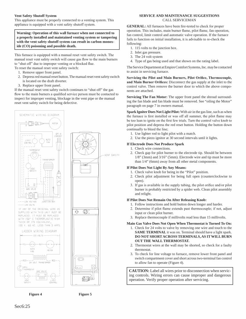
Sec6:25
Vent Safety Shutoff SystemThis appliance must be properly connected to a venting system. This appliance is equipped with a vent safety shutoff system.
This furnace is equipped with a manual reset vent safety switch. The manual reset vent safety switch will cause gas flow to the main burners to “shut off” due to improper venting or a blocked flue.To reset the manual reset vent safety switch:
1. Remove upper front panel.2. Depress red manual reset button. The manual reset vent safety switch
is located on the draft diverter.3. Replace upper front panel.
If the manual reset vent safety switch continues to “shut off” the gas flow to the main burners a qualified service person must be contacted to inspect for improper venting, blockage in the vent pipe or the manual reset vent safety switch for being defective.
Figure 4 Figure 5
Warning: Operation of this wall furnace when not connected to a properly installed and maintained venting system or tampering with the vent safety shutoff system can result in carbon monox-ide (CO) poisoning and possible death.
CAUTION: Label all wires prior to disconnection when servic-ing controls. Wiring errors can cause improper and dangerous operation. Verify proper operation after servicing.
SERVICE AND MAINTENANCE SUGGESTIONSCALL SERVICEMAN
GENERAL: All furnaces have been fire-tested to check for proper operation. This includes, main burner flame, pilot flame, fan operation, fan control, limit control and automatic valve operation. If the furnace fails to function on initial installation, it is advisable to re-check the following:
1. 115 volts to the junction box.2. Inlet gas pressure.3. The 24 volt system4. Type of gas being used and that shown on the rating label.
The Service Department at Empire Comfort Systems, Inc. may be contacted to assist in servicing furnace.
Servicing the Pilot and Main Burners, Pilot Orifice, Thermocouple, and Main Burner Orifices: Disconnect the gas supply at the inlet to the control valve. Then remove the burner door to which the above compo-nents are attached.
Servicing The Fan Motor: The upper front panel the shroud surround-ing the fan blade and fan blade must be removed. See “oiling the Motor” paragraph on page 7 in owners manual.
Spark Igniter Does Not Light Pilot: With air in the gas line, such as when the furnace is first installed or was off all summer, the pilot flame may be too lean to ignite on the first few trials. Turn the control valve knob to pilot position and depress the red reset button. Holding the button down continually to bleed the line;
1. Use lighter rod to light pilot with a match.2. Use the piezo ignitor at 30 second intervals until it lights.
If Electrode Does Not Produce Spark1. Check wire connections.2. Check gap for pilot burner to the electrode tip. Should be between
1/8” (3mm) and 3/16” (5mm). Electrode wire and tip must be more than 1/4” (6mm) away from all other metal components.
If Pilot Does Not Light By Any Means:1. Check valve knob for being in the “Pilot” position.2. Check pilot adjustment for being full open (counterclockwise to
open).3. If gas is available in the supply tubing, the pilot orifice and/or pilot
burner is probably restricted by a spider web. Clean pilot assembly and relight.
If Pilot Does Not Remain On After Releasing Knob:1. Follow instructions and hold button down longer and harder.2. Determine if pilot flame extends past thermocouple; if not, adjust
input or clean pilot burner.3. Replace thermocouple if millivolts read less than 15 millivolts.
Main Gas Valve Does Not Open When Thermostat is Turned To On:1. Check for 24 volts to valve by removing one wire and touch to the
SAME TERMINAL it was on. Terminal should have a light spark. DO NOT SHORT ACROSS TERMINALS, AS IT WILL BURN OUT THE WALL THERMOSTAT.
2. Thermostat wires at the wall may be shorted, so check for a faulty thermostat.
3. To check for line voltage to furnace, remove lower front panel and switch compartment cover and short across two-terminal fan control to allow fan to operate (Figure 4).
Sec6:26
FAW-55IP Series Heater Troubleshooting

Sec6:27
FOR YOUR SAFETY READ BEFORE OPERATINGWARNING: If you do not follow these instructions exactly, a fire or explosion may result
causing property damage, personal injury or loss of life.
A. This appliance is equipped with an ignition device which automatically lights the pilot.
Do not try to light the pilot by hand.
B. BEFORE OPERATING smell all around the appli-ance area for gas. Be sure to smell next to the floor because some gas is heavier than air and will settle on the floor.
WHAT TO DO IF YOU SMELL GAS• Do not try to light any appliance.• Do not touch any electrical switch; Do not use any phone in your building.• Immediately call your gas supplier from a neighbor’s
phone. Follow the gas supplier’s instructions.
• If you cannot reach your gas supplier, call the fire department.
C. Use only your hand to push in or turn the gas control knob. Never use tools. If the knob will not push in or turn by hand, don’t try to repair it; call a qualified service technician. Force or attempted repair may result in a fire or explosion.
D. Do not use this appliance if any part has been under water. Immediately call a qualified service technician to inspect the appliance and to replace any part of the control system and any gas control which has been under water.
1. STOP! Read the safety information above.
2. Set the thermostat to lowest setting.
3. Turn off all electric power to the appliance.
4. This appliance is equipped with an ignition device which automatically lights the pilot. Do not try to light the pilot by hand.
5. Remove control access panel (lower front panel).
6. Turn gas control knob clockwise to “OFF.”
7. Wait ten (10) minutes to clear out any gas. Then smell
for gas, including near the floor. If you smell gas, STOP! Follow “B” in the safety information above. If you don’t smell gas, go to the next step.
8. Turn gas control knob counterclockwise to “ON”.
9. Replace control access panel (lower front panel).
10. Turn on all electric power to the appliance.
11. Set thermostat to desired setting.
12. If the appliance will not operate, follow the instructions “TO TURN OFF GAS TO APPLIANCE” and call your service technician or gas supplier.
TO TURN OFF GAS TO APPLIANCE
OPERATING INSTRUCTIONS
1. Set the thermostat to lowest setting.
2. Turn off all electric power to the appliance if service is to be performed .
3. Remove control access panel (lower front panel).
4. Turn gas control knob clockwise to “OFF.” Do not force.
5. Replace control access panel (lower front panel).
LIGHTING INSTRUCTIONS

Sec6:28
Figure 2
Electrode and pilot must be kept clean. Clean through pilot access hole with a small brush (toothbrush) and water.Proper Main Burner FlameThe correct flame will be a short blue inner flame with a much larger light blue outer flame. The main burner (Figure 7) shows the approximate height of each part of the flame for each gas. The burner does not have a primary air adjustment. The flame will be correct if the factory-set pressure and orifice opening are used. After the furnace has been operating, the burner ports may be blocked by foreign matter carried in by combustion air. Therefore, cleaning of the burner may be needed for proper flame.To clean burner port disconnect the gas supply to the valve, and remove the eight screws fastening the burner door. After removing the burner door from the combustion chamber, remove rear burner, pilot burner and front burner. With front and rear burners removed from furnace, force water into the ribbon ports and dry with air pressure.
Figure 3Replacing Fan and Oiling the MotorThe fan motor should be cleaned and oiled once each heating season. To reach the motor, withdraw the metal shroud surrounding the fan blade by removing the screws on each side. Oil holes are located on the top at each end of the motor. Use a few drops of #10 motor oil. To clean the motor, blow air through its ventilation openings with a vacuum cleaner or low pressure air source.If fan motor is replaced, the silicone rubber gaskets, see owners amnual, page 14, Index No. 5, Part No. 712059 should also be replaced. The gaskets must be stretched to fit the motor bolts into the gasket holes and then the motor and gaskets installed on the motor mounting bars.
Checking Manifold PressureBoth Propane and Natural gas valves have a built-in pressure regulator in the gas valve. Natural gas models will have a manifold pressure of approximately 3.5” w.c. (.871kPa) at the valve outlet with the inlet pressure to the valve from a minimum of 5.0” w.c. (1.24kPa) for the purpose of input adjustment to a maximum of 10.5” w.c. (2.615kPa) Propane gas models will have a manifold pressure approximately 10.0” w.c. (2.49kPa) at the valve outlet with the inlet pressure to the valve from a minimum of 11.0” w.c. (2.739kPa) for the purpose of input adjustment to a maximum of 13.0” w.c. (3.237kPa). A 1/8” (3mm) N.P.T. plugged tapping, accessible for test gauge connection, is located on the outlet side of the gas control.The built-in regulator comes on at approximately 1/4th pressure and full on in 10 seconds.
Figure 1
High AltitudesFor altitudes/elevations above 2,000 feet (610m), input ratings should be reduced at the rate of 4 percent for each 1,000 feet (305m) above sea level. Canadian High Altitudes for locations having an elevation above mean sea level between 2,000 feet (610m) and 4,500 feet (1370m), the manifold pressure is to be decreased from 3.5” w.c. (.871kPa) to 2.8” w.c. (.697kPa) for Natural Gas and from 10.0” w.c. (2.49kPa) to 8.0” w.c. (1.992kPa) for Propane Gas.Proper Pilot FlameThe pilot flame (Figure 2) going to the spark must be large enough to completely cover the sparking area. With the proper flame, only 2 or 3 sparks will occur. More sparks indicate a small pilot flame and no ignition with spark stopping after approximately 90 seconds generally means not enough flame.To adjust pilot flame remove the pilot cover screw on the control valve (Figure 1), and turn the adjustment screw clockwise to reduce flame. Replace pilot cover screw to eliminate gas leakage.The pilot flame will appear large. A blue nearly horizontal flame is proper. The spark gap must be 1/8” (3mm) . A larger gap can result in the spark occurring some other place. The pilot flame and the spark gap are factory checked and tested.After use, cleaning may be required for the proper flame.Safety Lockout
S8600H module provides 100 percent shutoff, or safety lockout. If the pilot fails to light within 90 seconds, the control system will shut down. The control system must be reset by setting the thermostat below room temperature for one minute or by turning off power to the module for one minute.
4” (102mm) NAT6” (152mm) LP
1 ½”(38mm) NAT1/4” (6mm) LP
INSTALLATION
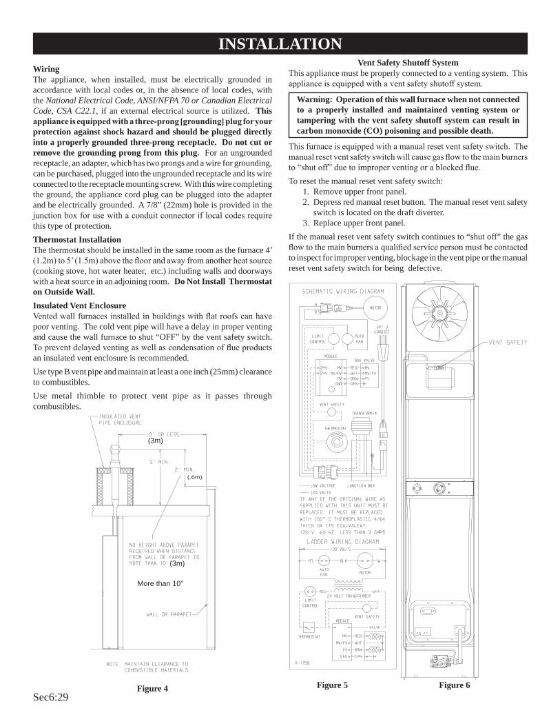
Sec6:29
Vent Safety Shutoff SystemThis appliance must be properly connected to a venting system. This appliance is equipped with a vent safety shutoff system.
Warning: Operation of this wall furnace when not connected to a properly installed and maintained venting system or tampering with the vent safety shutoff system can result in carbon monoxide (CO) poisoning and possible death.
This furnace is equipped with a manual reset vent safety switch. The manual reset vent safety switch will cause gas flow to the main burners to “shut off” due to improper venting or a blocked flue.To reset the manual reset vent safety switch: 1. Remove upper front panel. 2. Depress red manual reset button. The manual reset vent safety
switch is located on the draft diverter. 3. Replace upper front panel. If the manual reset vent safety switch continues to “shut off” the gas flow to the main burners a qualified service person must be contacted to inspect for improper venting, blockage in the vent pipe or the manual reset vent safety switch for being defective.
Figure 5 Figure 6
WiringThe appliance, when installed, must be electrically grounded in accordance with local codes or, in the absence of local codes, with the National Electrical Code, ANSI/NFPA 70 or Canadian Electrical Code, CSA C22.1, if an external electrical source is utilized. This appliance is equipped with a three-prong [grounding] plug for your protection against shock hazard and should be plugged directly into a properly grounded three-prong receptacle. Do not cut or remove the grounding prong from this plug. For an ungrounded receptacle, an adapter, which has two prongs and a wire for grounding, can be purchased, plugged into the ungrounded receptacle and its wire connected to the receptacle mounting screw. With this wire completing the ground, the appliance cord plug can be plugged into the adapter and be electrically grounded. A 7/8” (22mm) hole is provided in the junction box for use with a conduit connector if local codes require this type of protection.Thermostat InstallationThe thermostat should be installed in the same room as the furnace 4’ (1.2m) to 5’ (1.5m) above the floor and away from another heat source (cooking stove, hot water heater, etc.) including walls and doorways with a heat source in an adjoining room. Do Not Install Thermostat on Outside Wall.Insulated Vent EnclosureVented wall furnaces installed in buildings with flat roofs can have poor venting. The cold vent pipe will have a delay in proper venting and cause the wall furnace to shut “OFF” by the vent safety switch. To prevent delayed venting as well as condensation of flue products an insulated vent enclosure is recommended.Use type B vent pipe and maintain at least a one inch (25mm) clearance to combustibles.Use metal thimble to protect vent pipe as it passes through combustibles.
Figure 4
INSTALLATION
(3m)
(.6m)
(3m)
More than 10”
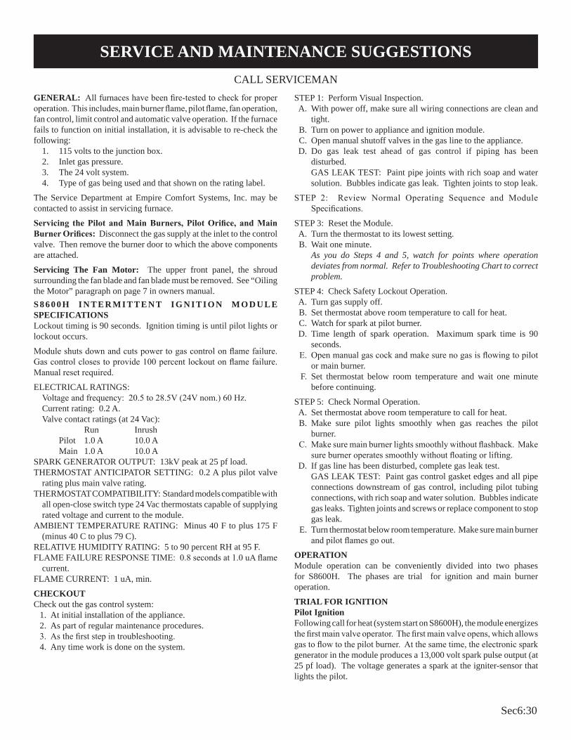
Sec6:30
CALL SERVICEMAN
SERVICE AND MAINTENANCE SUGGESTIONS
GENERAL: All furnaces have been fire-tested to check for proper operation. This includes, main burner flame, pilot flame, fan operation, fan control, limit control and automatic valve operation. If the furnace fails to function on initial installation, it is advisable to re-check the following:
1. 115 volts to the junction box.2. Inlet gas pressure.3. The 24 volt system.4. Type of gas being used and that shown on the rating label.
The Service Department at Empire Comfort Systems, Inc. may be contacted to assist in servicing furnace.
Servicing the Pilot and Main Burners, Pilot Orifice, and Main Burner Orifices: Disconnect the gas supply at the inlet to the control valve. Then remove the burner door to which the above components are attached.
Servicing The Fan Motor: The upper front panel, the shroud surrounding the fan blade and fan blade must be removed. See “Oiling the Motor” paragraph on page 7 in owners manual.S 8 6 0 0 H I N T E R M I T T E N T I G N I T I O N M O D U L E SPECIFICATIONSLockout timing is 90 seconds. Ignition timing is until pilot lights or lockout occurs.
Module shuts down and cuts power to gas control on flame failure. Gas control closes to provide 100 percent lockout on flame failure. Manual reset required.
ELECTRICAL RATINGS:Voltage and frequency: 20.5 to 28.5V (24V nom.) 60 Hz.Current rating: 0.2 A.Valve contact ratings (at 24 Vac): Run Inrush Pilot 1.0 A 10.0 A Main 1.0 A 10.0 A
SPARK GENERATOR OUTPUT: 13kV peak at 25 pf load.THERMOSTAT ANTICIPATOR SETTING: 0.2 A plus pilot valve
rating plus main valve rating. THERMOSTAT COMPATIBILITY: Standard models compatible with
all open-close switch type 24 Vac thermostats capable of supplying rated voltage and current to the module.
AMBIENT TEMPERATURE RATING: Minus 40 F to plus 175 F (minus 40 C to plus 79 C).
RELATIVE HUMIDITY RATING: 5 to 90 percent RH at 95 F.FLAME FAILURE RESPONSE TIME: 0.8 seconds at 1.0 uA flame
current.FLAME CURRENT: 1 uA, min.
CHECKOUTCheck out the gas control system: 1. At initial installation of the appliance. 2. As part of regular maintenance procedures. 3. As the first step in troubleshooting. 4. Any time work is done on the system.
STEP 1: Perform Visual Inspection. A. With power off, make sure all wiring connections are clean and
tight. B. Turn on power to appliance and ignition module. C. Open manual shutoff valves in the gas line to the appliance. D. Do gas leak test ahead of gas control if piping has been
disturbed. GAS LEAK TEST: Paint pipe joints with rich soap and water
solution. Bubbles indicate gas leak. Tighten joints to stop leak.
STEP 2: Review Normal Operating Sequence and Module Specifications.
STEP 3: Reset the Module. A. Turn the thermostat to its lowest setting. B. Wait one minute. As you do Steps 4 and 5, watch for points where operation
deviates from normal. Refer to Troubleshooting Chart to correct problem.
STEP 4: Check Safety Lockout Operation. A. Turn gas supply off. B. Set thermostat above room temperature to call for heat. C. Watch for spark at pilot burner. D. Time length of spark operation. Maximum spark time is 90
seconds. E. Open manual gas cock and make sure no gas is flowing to pilot
or main burner. F. Set thermostat below room temperature and wait one minute
before continuing.
STEP 5: Check Normal Operation. A. Set thermostat above room temperature to call for heat. B. Make sure pilot lights smoothly when gas reaches the pilot
burner. C. Make sure main burner lights smoothly without flashback. Make
sure burner operates smoothly without floating or lifting. D. If gas line has been disturbed, complete gas leak test. GAS LEAK TEST: Paint gas control gasket edges and all pipe
connections downstream of gas control, including pilot tubing connections, with rich soap and water solution. Bubbles indicate gas leaks. Tighten joints and screws or replace component to stop gas leak.
E. Turn thermostat below room temperature. Make sure main burner and pilot flames go out.
OPERATIONModule operation can be conveniently divided into two phases for S8600H. The phases are trial for ignition and main burner operation.
TRIAL FOR IGNITIONPilot IgnitionFollowing call for heat (system start on S8600H), the module energizes the first main valve operator. The first main valve opens, which allows gas to flow to the pilot burner. At the same time, the electronic spark generator in the module produces a 13,000 volt spark pulse output (at 25 pf load). The voltage generates a spark at the igniter-sensor that lights the pilot.

Sec6:31
If the pilot does not light, or the pilot flame current is not at least 1.0 uA and steady, the module will not energize the second main valve and the main burner will not light. Safety LockoutS8600H provides 100 percent shutoff, or safety lockout. A timer starts timing the moment the trial for ignition starts. Ignition spark continues only until the timed trial for ignition period ends. Then the module goes into safety lockout. Lockout de-energizes the first main valve operator and closes the first main valve in the gas control, stopping pilot gas flow. The control system must be reset by setting the thermostat below room temperature for one minute or by turning off power to the module for one minute.
Main Burner OperationWhen the pilot flame is established, a flame rectification circuit is completed between the sensor and burner ground. The flame sensing circuit in the module detects the flame current, shuts off the spark generator and energizes the second main valve operator. The second main valve opens and gas flows to the main burner, where it is ignited by the pilot burner. The flame current also holds the safety lockout timer in the reset (normal) operating condition.When the call for heat ends, both main valve operators are de-energized, and both main valves in the gas control close.
CAUTION: Label all wires prior to disconnection when servicing controls. Wiring errors can cause improper and dangerous operation. Verify proper operation after servicing.
Spark Generator PoweredFirst Valve (Pilot)Operator Opens
Pilot burner lights.Module senses flame current.
PILOT BURNER OPERATION
MODULE
S8600H
* Lockout timing is stamped on module.
RESPONSE
After 90 seconds*pilot valvecloses, spark stops.
OR
IF FLAME CURRENT SENSEDSpark generator offSecond valve operator(Main) opens.
MAIN BURNER OPERATIONModule monitors pilotflame current.
THERMOSTAT SATISFIEDValves close. Pilot andmain burners are off.
START
STAGE 1Trial for Ignition
STAGE 2Main BurnerOperation
END
S8600H NORMAL OPERATING SEQUENCE
Pilot burner does not light
Thermostat, Wall Switch,Remote, Etc. Calls for Heat
POWER INTERRUPTIONSystem shuts off. Restarts when
power is restored.PILOT FLAME FAILURE
Second main operator closes.Module starts trial for ignition.
SERVICE AND MAINTENANCE SUGGESTIONS

Sec6:32
Important 1. The following service procedures are provided as a general
guide. 2. Meter readings between gas control and ignition module must
be taken within the trial for ignition period. Once the ignition module locks out, the system must be reset by setting the thermostat down for at least one minute before continuing.
3. If any component does not function properly, make sure it is correctly installed and wired before replacing it.
4. The ignition module cannot be repaired. If it malfunctions, it must be replaced.
5. Only trained, experienced service technicians should service intermittent pilot systems.
Perform the CHECKOUT steps on page 10 as the first step in troubleshooting. Then check TROUBLESHOOTING GUIDE to pinpoint the cause of the problem. If troubleshooting indicates an ignition problem, see Ignition System Checks below to isolate and correct the problem.Following troubleshooting, perform the CHECKOUT procedure (page 10 ) again to be sure system is operating normally.Ignition System ChecksStep 1: Check ignition cable.Make sure: A. Ignition cable does not touch any metal surfaces. B. Ignition cable is no more than 36 inches (914mm) long. C. Connections to the ignition module and to the igniter-sensor
are clean and tight. D. Ignition cable provides good electrical continuity.Step 2: Check ignition system grounding. Nuisance shutdowns are often caused by a poor or erratic
ground. A. A common ground, usually supplied by the pilot burner
bracket, is required for the module and the pilot burner/igniter sensor.• Check for good metal-to-metal contact between the pilot
burner bracket and the main burner.• Check the ground lead from GND (BURNER) terminal on
the module to the pilot burner. Make sure connections are clean and tight. If the wire is damaged or deteriorated, replace it with No. 14-18 gauge, moisture-resistant, thermoplastic insulated wire with 105 C (221 F) minimum rating.• If flame rod or bracket are bent out of position, restore to
correct position.• Replace pilot burner/igniter sensor if insulator is
cracked.Step 3: Check spark ignition circuit. You will need a short jumper
wire made from ignition cable or other heavily insulated wire.
A. Close the manual gas valve. B. Disconnect the ignition cable at the SPARK terminal on the
module.
WARNINGWhen performing the following steps, do not touch stripped end of jumper or SPARK terminal. The ignition circuit generates 13,000 volts at 25 pf load and electrical shock can result.
C. Energize the module and immediately touch one end of the jumper
firmly to the GND terminal on the module. Move the free end of the jumper slowly toward the SPARK terminal until a spark is established.
D. Pull the jumper slowly away from the terminal and note the length of the gap when sparking stops. Check table below.
Step 4: Check pilot flame current. A. Turn off furnace at thermostat. B. Disconnect main valve wire from the TH or MV terminal on
the gas control. C. Disconnect ground wire from GND (BURNER) terminal at
module. D. Connect a meter (dc microamp scale) in series with the ground
lead. • Disconnect ground lead from GND terminal on ignition
module.• Connect the black (negative) meter lead to the ignition
module GND (BURNER) terminal.• Connect the red (positive) meter lead to the free end of the
ground lead. E. Set thermostat to call for heat. The spark will light the pilot but
the main burner will not light because the main valve actuator is disconnected.
F. Read the meter. The flame sensor current must be steady and at least 1.0 uA.
G. If the reading is less than the minimum or unsteady,• Make sure pilot flame envelopes 3/8 (9.5mm)to 1/2 inch
(13mm) of the flame rod. • If necessary, adjust pilot flame by turning the pilot
adjustment screw on the gas control clockwise to decrease or counterclockwise to increase pilot flame. Following adjustment, always replace pilot adjustment cover screw and tighten firmly to assure proper gas control operation.
• Check for cracked ceramic insulator, which can cause short to ground, and replace igniter-sensor if necessary.
• Make sure electrical connections are clean and tight. Replace damaged wire with moisture-resistant No. 18 wire rated for continuous duty up to 105 C (221 F).
H. Remove meter and reconnect all wires. Return system to normal operation before leaving job.
ARC LENGTH ACTIONNo arc or arc less than 1/8 inch (3mm).
Arc 1/8 inch (3mm) or longer.
Check external fuse, if provided.Verify power at module input termi-nal.Replace module if fuse and power okay.
Voltage output is okay.
TROUBLESHOOTING

Sec6:33
S8600H TROUBLESHOOTING GUIDE

Sec6:34
Green LED Status CodesGreen LED Flash Code
(X + Y)a Indicates Next System Action Recommended Service ActionOFF No “Call for Heat” Not applicable NoneFlash Fast Startup-Flame sense calibration Not applicable NoneHeart Beat Normal operation Not applicable None3 Recycle
- Flame failed during runInitiate new trial for ignition. Flash code will remain through the ignition trial until flame is proved.
If system fails to light on next trial for ignition, check gas supply, pilot burner, flame sense wiring, contamination of flame rod, burner ground connection.
4 Flame sensed out of sequence If situation self corrects within 10 sec-onds, control returns to normal sequence. If flame out of sequence remains longer than 10 seconds, control goes to Flash code 6 + 4 (see below).
Check for pilot flame. Replace gas valve if pilot flame present. If no pilot flame, cycle “Call for Heat.” If error repeats, replace control.
7 Flame sense leakage to ground Control remains in wait mode. When the fault corrects, control resumes nor-mal operation after a one minute delay.
Check flame sense lead wire for damage or shorting. Check that flame rod is in proper position.Check flame rod ceramic for cracks, damage or tracking.
8 Low secondary voltage supply - below 15.5 Vac)
Control remains in wait mode. When the fault corrects, control resumes nor-mal operation after a one minute delay.
Check transformer and AC line for proper input voltage to the control. Check with full system load on the transformer.
6 + 2 Failed trial for ignition resulting in lockout
Remain in lockout until “Call for Heat” is cycled.
Check gas supply, pilot burner, spark and flame sense wiring, flame rod con-taminated or out of position, burner ground connection.
6 + 3 More than 5 flame failures during run on the same “Call for Heat” resulting in lockout
Remain in lockout until “Call for Heat” is cycled.
Check gas supply, pilot burner, flame sense wiring, contamination of flame rod, burner ground connection.
6 + 4 Flame sensed out of sequence - longer than 10 seconds
Control waits until flame is no longer sensed and then goes to soft lockout. Flash code continues. Control auto re-sets from soft lockout after one hour.
Check for pilot flame. Replace gas valve if pilot flame present. If no pilot flame, cycle “Call for Heat.” If error repeats, replace control.
ON Soft lockout due to error detected during self check sequences
Control auto resets from soft lockout af-ter one hour.
Reset by cycling “Call for Heat.” If er-ror repeats, replace the control.
aFlash Code Descriptions: - Flash Fast: Rapid blinking - Heartbeat: Constant 1/2 second bright 1/2 second dim cycles - A single flash code number signifies that the LED flashes X times at 2Hz, remains off for two seconds,
and then repeats the sequence. - X + Y flash codes signify that the LED flashes X times at 2Hz, remains off for two seconds, flashes Y
times at 2Hz, remains off for three seconds, and then repeats the sequence.
S8600H TROUBLESHOOTING GUIDE

Sec6:35

Sec6:36
SERVICE NOTES

Sec6:37
SERVICE NOTES

Sec6:38

Sec7:1
Floor Furnace Troubleshooting

Sec7:2
DIAGNOSING FLOOR FURNACES

Sec7:3
DIAGNOSING FLOOR FURNACES

Sec7:4
DIAGNOSING FLOOR FURNACES

Sec7:5
DIAGNOSING FLOOR FURNACES
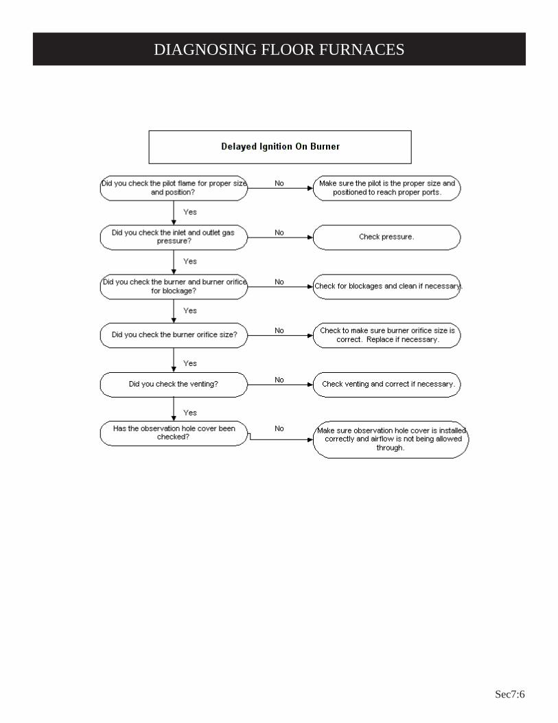
Sec7:6
DIAGNOSING FLOOR FURNACES
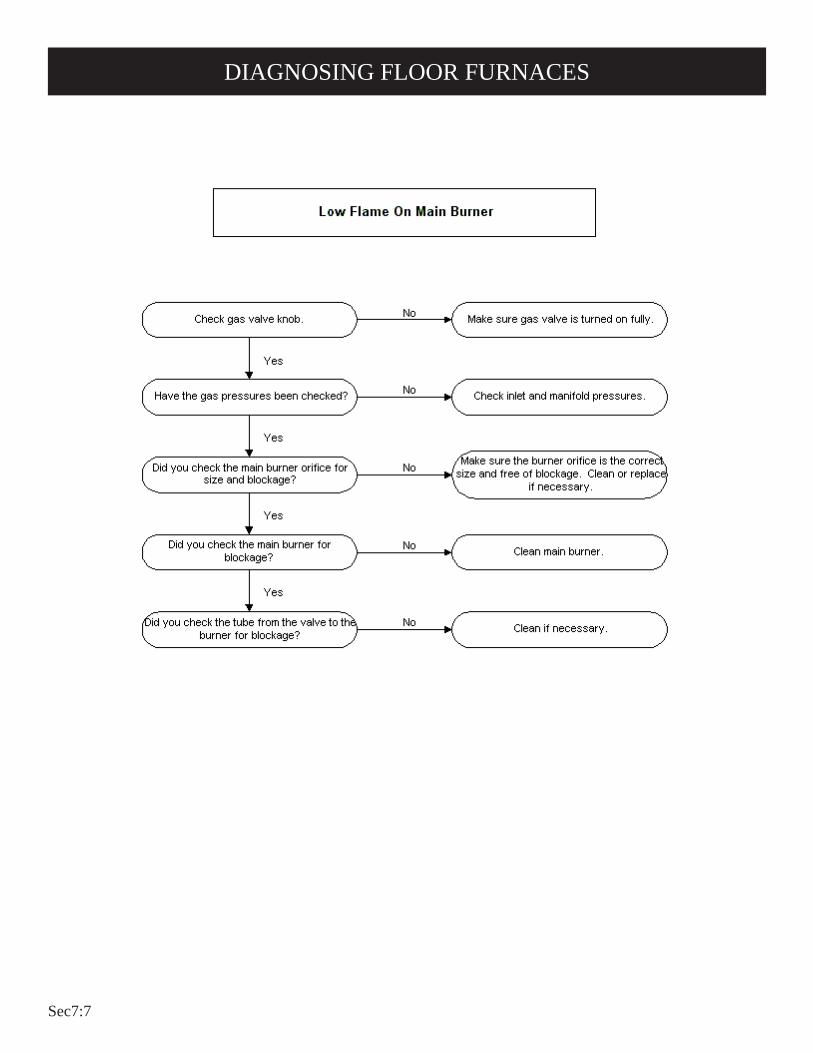
Sec7:7
DIAGNOSING FLOOR FURNACES
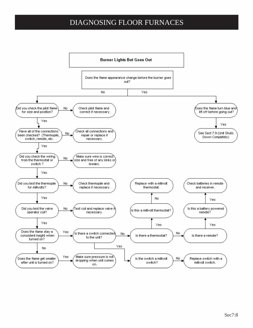
Sec7:8
DIAGNOSING FLOOR FURNACES

Sec7:9
DIAGNOSING FLOOR FURNACES
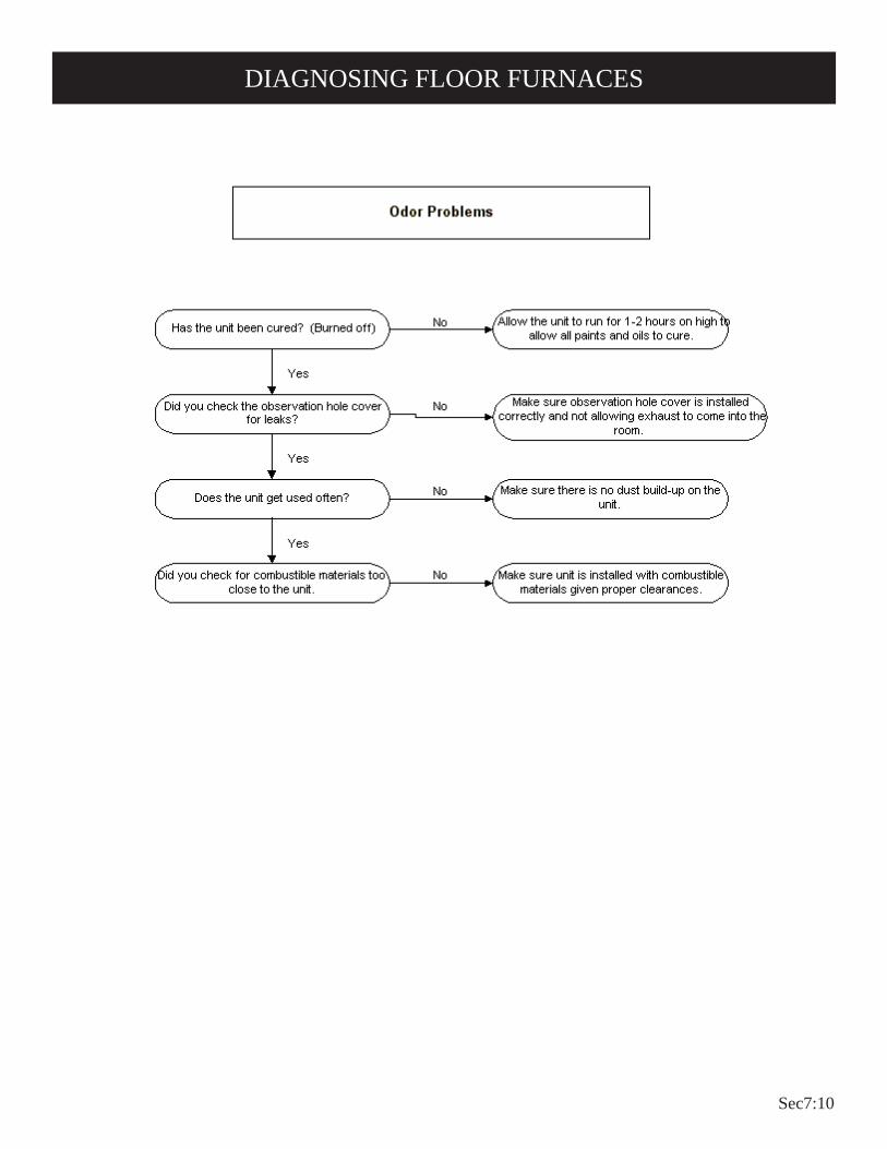
Sec7:10
DIAGNOSING FLOOR FURNACES

Sec7:11
DIAGNOSING FLOOR FURNACES

Sec7:12
FOR YOUR SAFETY READ BEFORE LIGHTINGWARNING: If you do not follow these instructions exactly, a fire or explosion may result caus-
ing property damage, personal injury or loss of life.
A. This appliance has a pilot which must be lighted by hand. When lighting the pilot, follow these instructions exactly.
B. BEFORE LIGHTING smell all around the appliance area for gas. Be sure to smell next to the floor because some gas is heavier than air and will settle on the floor.
WHAT TO DO IF YOU SMELL GAS • Do not try to light any appliance. • Do not touch any electrical switch; do not use any
phone in your building. • Immediately call your gas supplier from a neighbor's
phone. Follow the gas supplier's instructions.
• If you cannot reach your gas supplier, call the fire department.
C. Use only your hand to push in or turn the gas control knob. Never use tools. If the knob will not push in or turn by hand, don't try to repair it, call a qualified service tech-nician. Force or attempted repair may result in a fire or explosion.
D. Do not use this appliance if any part has been under water. Immediately call a qualified service technician to inspect the appliance and to replace any part of the control system and any gas control which has been under water.
LIGHTING INSTRUCTIONS
1. STOP! Read the safety information above.
2. Set the thermostat to lowest setting.
3. Remove floor register. NOTE: The gas control rod is attached to the gas control
knob.
4. Push in gas control rod slightly and turn clockwise to "OFF."
NOTE: Rod cannot be turned from "PILOT" to "OFF" unless rod is pushed in slightly. Do not force.
5. Remove the pilot access cover located on the combustion chamber.
6. Wait ten (10) minutes to clear out any gas. Then smell for gas, including near the floor. If you smell gas, STOP! Follow "B" in the safety information above. If you don't smell gas, go to the next step.
7. Find pilot - the pilot is adjacent to the center portion of the main burner in the area di-rectly below the pilot access opening.
8. Turn gas control rod counterclockwise to "PI-LOT."
9. Push and hold control rod in and repeatedly push the ignitor button until pilot is lit (or use match and lighter rod to light.) Continue to hold the control rod in for about one (1) minute after the pilot is lit. Release rod and it will pop back up. Pilot should remain lit. If it goes out, repeat steps 4 through 9.
• If rod does not pop up when released, stop and im-mediately call a qualified service technician or gas supplier.
• If the pilot will not stay lit after several tries, turn the gas control rod to "OFF" and call your service technician or gas supplier.
10. Replace pilot access cover. 11. Turn gas control knob counterclockwise to
"ON." 12. Replace floor register.13. Set thermostat to desired setting.
TO TURN OFF GAS TO APPLIANCE1. Set the thermostat to lowest setting.
2. Remove floor register.
3. Push in gas control rod slightly and turn clockwise to "OFF." Do not force.
4. Replace floor register.
3588 50887088

Sec7:13
PROPER MAIN BURNER FLAME AND PILOT FLAME 3588
Figure 1The correct pilot flame will be blue and extend past the thermopile as shown in the drawing. LP gas models do not require adjusting. The input of Natural gas models will require adjusting if the inlet pressure to the valve is above 5" w.c.
PROPER MAIN BURNER FLAME 5088, 7088
Figure 2 Inner Cone Outer Cone Carry down flameModel Gas (A) Dark blue (B) Light blue (C) Blue 7088 Nat 1 inch 2 1/2 inches 1/4 inch LP 3/4 inch 2 inches small cone5088 Nat. 3/4 inch 2 inches 3/16 inch LP 1/2 inch 1 1/2 inch small cone
DO NOT MISTAKE AN ORANGE FLAME CAUSED BY PAR-TICLES IN THE AIR FOR THE UNDESIRABLE YELLOW FLAME.
Figure 3
PROPER PILOT BURNER FLAME 5088, 7088A blue flame shooting toward the main burner with an inner blue cone and a larger light blue outer flame. The generator will be surrounded by a blue flame that terminates near the top of the generator.
HIGH ALTITUDESOrifice size must be reduced for high altitude use, or carbon monoxide may be generated and excessive heat will seriously damage the unit. When altitudes over 2,000 feet are specified, in the United States, main burner spuds will be furnished to reduce input 4% for each 1,000 feet of altitude above sea level. Contact the manufacturer or your gas company before changing spud sizes.
CHECKING MANIFOLD PRESSUREBoth Propane and Natural gas valves have a built-in pressure regulator in the gas valve with factory-set adjustment. Natural gas models should have a manifold pressure of approximately 3.5" w.c. at the valve outlet with the inlet pressure to the valve from a minimum of 5.0" w.c. for the purpose of input of input adjustment to a maximum of 7.0" w.c. Propane gas models will have a manifold pressure approximately 10.0" w.c. at the valve outlet with the inlet pressure to the valve from a minimum of 11.0" w.c. for the purpose of input adjustment to a maximum of 13.0" w.c.An 1/8" N.P.T. plugged tapping, accessible for test gage connection, is located on the outlet side of the gas control.
CLEANING THE MAIN BURNERRemove the burner and apply air pressure inside the throat of the burner and down into the ports.Check for proper burner and pilot flame before and during each heating season.
SERVICINGINSTALLATION AND REPAIR SHOULD BE DONE BY A QUALIFIED SERVICE PERSON. The appliance should be inspected before use and at least annually by a professional service person. More frequent cleaning may be required due to excessive lint from carpeting, bedding material, etc. It is imperative that control compartments, burners and circulating air passageways of the appliance be kept clean.
Floor furnace must not be connected to a chimney flue servicing a separate solid-fuel burning appliance.
DON'T put anything around the furnace that will obstruct the flow of combustion and ventilation air.
DO keep the appliance area clear and free from combustible material, gasoline and other flammable vapors and liquids.
DO examine venting system periodically and replace damaged parts.
DO examine burners periodically. Clean and replace damaged parts.
MAKE periodic visual check of pilot and burner flame.
B
A
C
FLAME 360° AROUNDGENERATOR - COMINGTO TOP OF GENERATOR

Sec7:14
Wiring Diagram

Sec7:15
SOME HELPFUL WARNINGS
• Use low heat output when children are nearby.• Do not cover the floor register when the furnace or pilot is
turned on.• Do not restrict the flow of air around the register by placing a
screen under it.• Do not dry clothes or any objects by putting them on floor
register because this creates a fire hazard.
Figure 4• Do not hang clothes or any object above or over floor register
because this too creates a fire hazard.• During warm weather months, turn to full OFF position before
you cover the register with a rug, because this too creates a fire hazard.
CAUTIONNEVER run your furnace with the lighter hole open or with a broken lighter hole window. Exhaust gases can get into the living area through an open lighter hole and be fatal.
PIEzO LIGHTING INSTRUCTIONSThis unit is equipped with a Piezo (spark) for lighting the pilot without removing the lighter hole cover. A lighter rod is supplied and can be used to see if the pilot is getting gas and also for faster lighting when there is excessive air in the lines.
REGISTER TEMPERATURE CONTROLSThe register temperature control has two positions. LOW HEAT (Black) output and FULL HEAT (Red) output. Use the low posi-tion when children are present. This will cause your furnace to turn off and on several times before the living area is completely comfortable. This is normal and limits the register temperature to a maximum of 235°F.
CAUTIONContact of bare skin on the hot air register may result in burns when the appliance is in operation. KEEP CHILDREN OFF!You can reduce the heat of the register by moving the register temperature control.
MILLIVOLT INFORMATION500 average with the thermostat OFF.225 average with the thermostat ON.
140 minimum for valve to open.65 minimum for pilot to stay on.
CAUTION: Label all wires prior to disconnection when servic-ing controls. Wiring errors can cause improper and dangerous operation. Verify operation after servicing.
A. All units have been fire-tested to check the operation of the furnace. This includes the BTU input, main burner flame, pilot flame, limit controls and automatic operation. If problems are encountered on initial installation the following should be checked1. Is the unit equipped for the gas being used?2. Are all of the wires connected to the gas valve properly?3. Is the venting system functioning? Check for spillage at
the diverter.4. Is the gas inlet pressure proper? Read instructions for
minimum pressure.B. It is necessary to use a millivolt meter to determine if the power
from the generator is adequate. 500 millivolts is normal with the thermostat off and 140 millivolts minimum with thermostat on.
C. This floor furnace cannot be expected to function properly if exposed to wind as found when installed in a house supported by pillars (open foundation). The wind is most harmful if it can go beneath the front of the draft diverter and produce a pressure directly on the outlet of the chamber. This wind can result in pilot outage and a reduction in millivolts, causing the valve not to open.
D. Good operation of the system is dependent on the pilot and generator working properly. It is possible for the pilot to require cleaning yearly. Replace pilot assembly if cleaning does not produce proper flame. Replacement on generator alone is not recommended.
E. Gas Valve will not open. To determine problem area:1. By-pass thermostat on the wall.2. By-pass thermostat at the valve.3. By-pass limit and thermostat at the valve.4. Check millivolts.
TROUBLESHOOTING INFORMATION
OPERATING INFORMATION

Sec7:16
SERVICE NOTES

Sec7:17
SERVICE NOTES
Sec8:1
Control Valve and Control Devices

Sec8:2
MA
NU
AL
PILO
TPi
lot B
arre
l
Cer
amic
Igni
tor
Ther
moc
oupl
e
Air
Mix
er
Gas
Inle
t

Sec8:3
MIL
LIV
OLT
PIL
OT Gas
Inle
t
Ther
mop
ile
Pilo
t Bar
rel

Sec8:4
Mounting Nut
Hot Junction
450° temperaturedifference between Hot and Cold Junction
Cold Junction
Thermopile Lead
Negative Terminal(White)
Positive Terminal(Red)
750 MV Maximum
Thermopile

Sec8:5
Gas Inlet
Pilot Barrel
Thermocouple
Spark Ignitor
IP Pilot

Sec8:6
1956
5 - H
ot S
urfa
ce Ig
nito
r D
V-E
Serie
s

Sec8:7
Gas
Con
trol L
ever
Gas
Inle
t
Valv
e St
em /
Con
verta
ble
Reg
ulat
or
Gas
Out
let
(Not
Sho
wn)
24V
Ele
ctric
al
Term
inal
s
R32
37- N
ATR
3238
- LP
24 V
olt C
ontro
l Val
ve D
V-E
Serie
s

Sec8:8
Gas
Coc
k
Pilo
t Sup
ply
Out
let
Gas
Inle
tG
as O
utle
t
Inle
t Pre
ssur
e Ta
p
Man
ifold
Pre
ssur
e Ta
p
Pilo
t Adj
ustm
ent
Scre
w
MV
/ PV
Ter
min
als
Valv
e O
pera
tor T
erm
inal
s
R21
48 -
NAT
R56
55 -
LP
Pilo
t Res
et B
utto
n
24 V
olt C
ontro
l Val
ve D
V55
, DV
C35
FAW
40/5
5 Se
ries S
erie
s

Sec8:9
Gas
Coc
k
Pilo
t Sup
ply
Out
let
Inle
t Pre
ssur
e Ta
p
Man
ifold
Pre
ssur
e Ta
p
Bul
b Th
erm
osta
t
R65
63- N
AT/L
PH
ydra
ulic
Con
trol V
alve
SR
and
BF
Serie
s

Sec8:10
Gas
Coc
k
Pilo
t Sup
ply
Out
let
Gas
Inle
t
Gas
Out
let
Man
ifold
Reg
ulat
or
Pilo
t Adj
ustm
ent
Scre
w
Pilo
t Circ
uit W
ire (E
PU)
Reg
ulat
or V
ent
R52
45 -
NAT
R52
46 -
LP
TH/T
P
TP
TH
Mill
ivol
t Con
trol V
alve
GW
T Se
ries

Sec8:11
Inle
t Pre
ssur
e Ta
p
Man
ifold
Pre
ssur
e Ta
p
Gas
Coc
k
Pilo
t Sup
ply
Out
let
Gas
Inle
t
Gas
Out
let
Man
ifold
Reg
ulat
or
Pilo
t Adj
ustm
ent
Scre
wPi
lot C
ircui
t Wire
(EPU
) Reg
ulat
or V
ent
R55
98- N
ATR
5599
- LP
TH/T
P
TP
TH
Mill
ivol
t Con
trol V
alve
DV
210/
215
Serie
s

Sec8:12
Inle
t Pre
ssur
e Ta
p
Man
ifold
Pre
ssur
e Ta
p
Gas
Coc
k
Pilo
t Sup
ply
Out
let
Gas
Inle
t
Gas
Out
let
Man
ifold
Reg
ulat
or
Pilo
t Adj
ustm
ent
Scre
wPi
lot C
ircui
t Wire
(EPU
)
Reg
ulat
or V
ent
R56
00 -
NAT
R56
01 -
LP
TH/T
P
TP
TH
Mill
ivol
t Con
trol V
alve
DV
25/3
5 Se
ries

Sec8:13
Inle
t Pre
ssur
e Ta
p
Man
ifold
Pre
ssur
e Ta
pC
ontro
l Rod
Bra
cket
Gas
Coc
k
Pilo
t Sup
ply
Out
let
Gas
Inle
t
Gas
Out
let
Man
ifold
Reg
ulat
or
Pilo
t Adj
ustm
ent
Scre
wPi
lot C
ircui
t Wire
(EPU
)
Reg
ulat
or V
ent
R56
06 -
NAT
R56
05 -
LP TH/T
P
TP TH
Mill
ivol
t Con
trol V
alve
Flo
or F
urna
ce S
erie
s

Sec8:14
Gas
Coc
k
Gas
Inle
t
Gas
Out
let
Inle
t Pre
ssur
e Ta
pM
anifo
ld P
ress
ure
Tap
Hig
h / L
ow A
djst
men
t Kno
b
Bul
b Th
erm
osta
t
R61
03 -
NAT
R61
04 -
LPH
ydra
ulic
Con
trol V
alve
RH
25/3
5 Se
ries

Sec8:15
DIAGNOSING THERMOSTATS

Sec8:16
DIAGNOSING WALL SWITCHES

Sec8:17
SERVICE NOTES

Sec8:18
SERVICE NOTES

Sec8:19

Sec9:1
Vented and Vent Free Sizing Charts


Ro
om
Siz
e C
har
t fo
r Ven
t-F
ree
Hea
ters
Squa
re F
eet
BTU
Zone
Appr
oxim
ate
Room
Size
BTU
Zone
Mod
elBT
U/HR
Inpu
tBT
U/HR
Outp
ut1
23
45
12
34
5
Infra
red/
Blue
Fla
me
Heat
ers
SR6,
HB0
6, H
R06
6,00
06,
000
750
375
250
188
150
27 x
27
19 x
19
16 x
16
14 x
14
12 x
12
SR10
, SR1
0T, B
F10,
HB
10, H
R10
10,0
0010
,000
1250
625
417
313
250
35 x
35
25 x
25
20 x
20
18 x
18
16 x
16
HR15
15,0
0015
,000
1875
938
625
469
375
43 x
43
31 x
31
25 x
25
22 x
22
19 x
19
HR17
17,0
0017
,000
2125
1063
708
531
425
46 x
46
33 x
33
27 x
27
23 x
23
21 x
21
SR18
, SR1
8T, H
R18
18,0
0018
,000
2250
1125
750
563
450
47 x
47
34 x
34
27 x
27
24 x
24
21 x
21
BF20
, HB2
0, H
R20
20,0
0020
,000
2500
1250
833
625
500
50 x
50
35 x
35
29 x
29
25 x
25
22 x
22
HR25
25,0
0025
,000
3125
1563
1042
781
625
56 x
56
40 x
40
32 x
32
28 x
28
25 x
25
SR30
, SR3
0T, B
F30,
HB
30, H
R30
30,0
0030
,000
3750
1875
1250
938
750
61 x
61
43 x
43
35 x
35
31 x
31
27 x
27
Log
Set B
urne
rs
VFDR
-18L
B10
10,0
0010
,000
1250
625
417
313
250
35 x
35
25 x
25
20 x
20
18 x
18
16 x
16
VF (S
R, S
V)-1
625
,000
25,0
0031
2515
6310
4278
162
556
x 5
640
x 4
032
x 3
228
x 2
825
x 2
5
VFD
(R, M
, T)-
18LB
28,0
0028
,000
3500
1750
1167
875
700
59 x
59
42 x
42
34 x
34
30 x
30
26 x
26
VFS
(M, R
, V)-
1832
,000
32,0
0040
0020
0013
3310
0080
063
x 6
345
x 4
537
x 3
732
x 3
228
x 2
8
VFD
(M, R
, T)-
24LB
34,0
0034
,000
4250
2125
1417
1063
850
65 x
65
46 x
46
38 x
38
33 x
33
29 x
29
VFS
(M, R
, V)-
2436
,000
36,0
0045
0022
5015
0011
2590
067
x 6
747
x 4
739
x 3
934
x 3
430
x 3
0
VFS
(M, R
, V)-
3038
,000
38,0
0047
5023
7515
8311
8895
069
x 6
949
x 4
940
x 4
034
x 3
431
x 3
1
VFD
(R,M
,T)-
30LB
40
,000
40,0
0050
0025
0016
6712
5010
0071
x 7
150
x 5
041
x 4
135
x 3
532
x 3
2
Fire
plac
e/He
arth
s
VF-2
4FP2
, VF
D26F
P30L
1010
,000
10,0
0012
5062
541
731
325
035
x 3
525
x 2
520
x 2
018
x 1
816
x 1
6
VF-2
4-FP
(2,3
) VFD
-26
(FM
) (FP
) (20
,30)
20,0
0020
,000
2500
1250
833
625
500
50 x
50
35 x
35
29 x
29
25 x
25
22 x
22
VFB
(H, L
) 30
30,0
0030
,000
3750
1875
1250
938
750
61 x
61
43 x
43
35 x
35
31 x
31
27 x
27
VFP3
232
,000
32,0
0040
0020
0013
3310
0080
063
x 6
345
x 4
537
x 3
732
x 3
228
x 2
8
VFP3
636
,000
36,0
0045
0022
5015
0011
2590
067
x 6
747
x 4
739
x 3
934
x 3
430
x 3
0
Herit
age
Cast
Iron
Sto
ves
VFP-
30-C
A30
32,0
0032
,000
4000
2000
1333
1000
800
63 x
63
45 x
45
37 x
37
32 x
32
28 x
28
QU
ICK
RE
FE
RE
NC
E (
Bas
ed o
n C
eilin
g H
eigh
t of 8
Fee
t)
Use
th
is C
har
t as
Gu
ide
On
ly.
Co
nsu
lt y
ou
r In
stal
ler/
Dea
ler
for
Fin
al
Mo
del
/Siz
e D
eter
min
atio
n
1. M
ultip
ly th
e sq
uare
feet
of a
rea
by th
e
ce
iling
hei
ght t
o de
term
ine
cubi
c fe
et.
2. D
eter
min
e B
TU
zon
e fr
om m
ap o
n ot
her
side
, eith
er z
one
1, 2
, 3, 4
, or
5.3.
Mul
tiply
the
cubi
c fe
et b
y yo
ur B
TU
zon
e.
T
his
num
ber
will
be
the
BT
U/H
Out
put
th
at is
req
uire
d to
hea
t you
r ar
ea.
4. G
o to
the
BT
U/H
Out
put c
olum
n to
mat
ch a
s cl
osel
y as
pos
sibl
e yo
ur B
TU
n
eeds
with
hea
ter
outp
ut.
Sev
eral
he
ater
s w
ill h
ave
the
requ
ired
BT
U o
utpu
t
to h
eat y
our
area
.5.
Ple
ase
have
you
r E
mpi
re d
eale
r ex
plai
n
the
feat
ures
of t
he d
iffer
ent t
ypes
of
h
eate
rs a
vaila
ble.
Exa
mpl
e: R
oom
Siz
e is
28’
x 2
8’
Cei
ling
Hei
ght i
s 8’
B
TU
Zon
e is
4
28’
x 2
8’ x
8’ x
4 =
25,
088
B
TU
/H O
utpu
t
Empi
re C
omfo
rt Sy
stem
s Inc
.91
8 Fr
eebu
rg A
venu
eB
elle
ville
, IL
6222
0
6/09
*See
map
on
oppo
site
sid
e to
det
erm
ine
BTU
Zone
for y
our l
ocat
ion.
Note
: • N
ot a
ll he
ater
mod
els
are
allo
wed
by
som
e lo
cal c
odes
; i.e
., Ve
nt-F
ree.
Be s
ure
the
heat
er m
odel
you
hav
e ch
osen
is a
llow
ed in
you
r are
a.
• At
hig
h al
titud
es, a
dditi
onal
hea
t may
be
requ
ired
•
If yo
u ha
ve a
sin
gle
room
with
4 e
xter
ior w
alls
, add
ition
al h
eat m
y be
requ
ired.


Ro
om
Siz
e C
har
t fo
r Ven
ted
Hea
ters
Squa
re F
eet
BTU
Zone
Appr
oxim
ate
Room
Size
BTU
Zone
Mod
elBT
U/HR
Inpu
tBT
U/HR
Outp
ut1
23
45
12
34
5
Dire
ct-V
ent W
all F
urna
ces
DV-5
555
,000
42,0
0052
5026
2517
5013
1210
5072
x 7
251
x 5
142
x 4
236
x 3
632
x 3
2
DVC-
3535
,000
27,7
0034
6217
3111
5486
569
259
x 5
942
x 4
234
x 3
429
x 2
926
x 2
6
DV-3
535
,000
24,5
0030
6315
3110
2176
661
355
x 5
539
x 3
932
x 3
228
x 2
825
x 2
5
DV-2
525
,000
17,5
0021
8710
9372
854
643
747
x 4
733
x 3
327
x 2
723
x 2
321
x 2
1
DV-2
1515
,000
10,5
0013
1265
647
832
826
236
x 3
627
x 2
722
x 2
218
x 1
816
x 1
6
DV-2
1010
,000
7,00
087
543
729
121
817
530
x 3
017
x 1
717
x 1
715
x 1
513
x 1
3
Dire
ct-V
ent W
all F
urna
ces
DV-2
0E20
,000
16,0
0020
5011
0080
060
050
045
x 4
533
x 3
328
x 2
824
x 2
422
x 2
2
DV-4
0E40
,000
32,0
0039
0021
0014
5011
2595
063
x 6
347
x 4
738
x 3
833
x 3
331
x 3
1
DV-5
5E55
,000
44,0
0053
5028
019
0015
0011
7573
x 7
353
x 5
344
x 4
438
x 3
834
x 3
4
Room
Hea
ters
RH-6
565
,000
45,5
0056
8728
4318
9514
2111
3775
x 7
553
x 5
344
x 4
438
x 3
834
x 3
4
RH-5
050
,000
35,0
0043
7521
8714
5810
9387
566
x 6
647
x 4
738
x 3
833
x 3
330
x 3
0
RH-3
535
,000
24,5
0030
6015
3010
2076
561
255
x 5
539
x 3
932
x 3
228
x 2
825
x 2
5
RH-2
525
,000
17,5
0021
8710
9372
954
643
747
x 4
733
x 3
327
x 2
723
x 2
321
x 2
1
Grav
ity W
all F
urna
ces
GWT-
5050
,000
37,0
0046
2523
1215
4111
5692
568
x 6
848
x 4
839
x 3
934
x 3
430
x 3
0
GWT-
3535
,000
25,9
0032
3716
1310
7980
964
757
x 5
740
x 4
032
x 3
228
x 2
825
x 2
5
GWT-
2525
,000
18,5
0023
1211
5677
057
846
248
x 4
834
x 3
428
x 2
824
x 2
421
x 2
1
Coun
terfl
ow V
ente
d W
all F
urna
ces
FAW
-55
55,0
0042
,000
5250
2625
1750
1312
1050
72 x
72
51 x
51
42 x
42
36 x
36
32 x
32
FAW
-40
40,0
0031
,000
3875
1937
1291
968
775
63 x
63
44 x
44
36 x
36
31 x
31
28 x
28
Floo
r Fur
nace
s
7088
65,0
0045
,500
5687
2843
1895
1421
1137
75 x
75
53 x
53
44 x
44
38 x
38
34 x
34
5088
45,0
0031
,500
3937
1968
1312
984
787
63 x
63
44 x
44
36 x
36
31 x
31
28 x
28
3588
32,5
0022
,750
2843
1421
947
710
568
53 x
53
38 x
38
31 x
31
27 x
27
24 x
24
Herit
age
Cast
Iron
Sto
ves
DVP-
30-C
A30
30,0
0021
,000
2625
1312
875
656
525
51 x
51
36 x
36
30 x
30
26 x
26
23 x
23
Man
tis
FW/F
I/FF-
2828
,000
25,2
0035
0017
0012
2595
077
539
x 3
942
x 4
235
x 3
531
x 3
128
x 2
8
BF/B
I/BP-
2828
,000
25,2
0035
0017
0012
2595
077
539
x 3
942
x 4
235
x 3
531
x 3
128
x 2
8
QU
ICK
RE
FE
RE
NC
E (
Bas
ed o
n C
eilin
g H
eigh
t of 8
Fee
t)U
se t
his
Ch
art
as G
uid
e O
nly
.C
on
sult
yo
ur
Inst
alle
r/D
eale
r fo
r F
inal
M
od
el/S
ize
Det
erm
inat
ion
1. M
ultip
ly th
e sq
uare
feet
of a
rea
by th
e
ce
iling
hei
ght t
o de
term
ine
cubi
c fe
et.
2. D
eter
min
e B
TU
zon
e fr
om m
ap o
n ot
her
side
, eith
er z
one
1, 2
, 3, 4
, or
5.3.
Mul
tiply
the
cubi
c fe
et b
y yo
ur B
TU
zon
e.
T
his
num
ber
will
be
the
BT
U/H
R O
utpu
t
that
is r
equi
red
to h
eat y
our
area
.4.
Go
to th
e B
TU
/HR
Out
put c
olum
n to
mat
ch a
s cl
osel
y as
pos
sibl
e yo
ur B
TU
nee
ds w
ith h
eate
r ou
tput
. S
ever
al
heat
ers
may
hav
e th
e re
quire
d B
TU
out
put t
o he
at y
our
area
.5.
Ple
ase
have
you
r E
mpi
re d
eale
r
exp
lain
the
feat
ures
of t
he d
iffer
ent
type
s of
hea
ters
.
Exa
mpl
e: R
oom
Siz
e is
28’
x 2
8’
Cei
ling
Hei
ght i
s 8’
B
TU
Zon
e is
4
28’
x 2
8’ x
8’ x
4 =
25,
088
B
TU
/H O
utpu
t
Empi
re C
omfo
rt Sy
stem
s Inc
.91
8 Fr
eebu
rg A
venu
eB
elle
ville
, IL
6222
0
7/09
*See
map
on
oppo
site
sid
e to
det
erm
ine
BTU
Zone
for y
our l
ocat
ion.
Note
: • N
ot a
ll he
ater
mod
els
are
allo
wed
by
som
e lo
cal c
odes
; i.e
., Ve
nt-F
ree.
Be
sure
the
heat
er m
odel
you
hav
e ch
osen
is a
llow
ed in
you
r are
a.
•
At h
igh
altit
udes
, add
ition
al h
eat m
ay b
e re
quire
d.
•
If y
ou h
ave
a si
ngle
room
with
4 e
xter
ior w
alls
, add
ition
al h
eat m
y be
requ
ired.

Sec9:6
Sec10:1
Service Bulletins

Sec10:2

Sec11:1
Suggested Parts List

Sec11:2
HEAT
ER S
UG
GES
TED
PA
RTS
LIST
PA
RT N
UM
BER
M
AN
UFA
CTU
RER
MA
N P
ART
#SR
6, 1
0, 1
0T, 1
8, 1
8T, 3
0, 3
0T-3
R
6307
NAT
PIL
OT
ASS
Y
C
OPR
ECI,
S. C
OO
P., L
TDA
.
OD
S 21
500/
144
R63
08 L
P PI
LOT
ASS
Y
C
OPR
ECI,
S. C
OO
P., L
TDA
.
OD
S 21
.500
/206
R23
13 P
IEzO
IGN
ITO
R
C
HA
NN
EL P
RO
DU
CTS
, IN
C.
12
44-4
4
SKG
ITA
LIA
S.P
.A.
00
G01
30-0
1R
2277
VA
LVE
LP &
NAT
S.I.T
. CO
NTR
OLS
USA
, IN
C.
R
-227
7
AR
CH
ER M
AR
KET
ING
CO
RP.
GH
3960
1000
1
CO
PREC
I, S.
CO
OP.
, LTD
A.
R65
63 V
ALV
E LP
& N
AT
T SE
RIE
S
S.I.T
. CO
NTR
OLS
USA
, IN
C.
63
0568
R16
49 V
ALV
E LP
& N
AT
A
RC
HER
MA
RK
ETIN
G C
OR
P.
G
H39
6002
001
C
OPR
ECI,
S. C
OO
P., L
TDA
.
BF
10, 2
0, 3
0-2
R65
63 V
ALV
E LP
& N
AT
S.
I.T. C
ON
TRO
LS U
SA, I
NC
.
6305
68R
6306
NAT
PIL
OT
ASS
Y
C
OPR
ECI,
S. C
OO
P., L
TDA
.
OD
S 21
500/
142
R63
08 L
P PI
LOT
ASS
Y
C
OPR
ECI,
S. C
OO
P., L
TDA
.
OD
S 21
.500
/206
R63
09 S
PAR
K IG
NIT
OR
R63
10 T
HER
MO
CO
UPL
E
CO
PREC
I, S.
CO
OP.
, LTD
A.
T1
1300
/611
X75
0
DV
210
/ 21
5-7S
G
M15
5 O
BS
HO
LE G
ASK
ET
GA
SKET
& S
EAL
M
-155
R10
55 E
LEC
TRO
DE
& W
IRE
CH
AN
NEL
PR
OD
UC
TS, I
NC
.
1647
-41
R10
54 T
HER
MO
PILE
HO
NEY
WEL
L, IN
C.
Q31
3A 1
261/
BR
2890
LP
GA
S PI
LOT
H
ON
EYW
ELL,
INC
.
Q
314A
673
0/B
R28
93 N
AT G
AS
PILO
T
HO
NEY
WEL
L, IN
C.
Q31
4A 6
722/
BR
5598
NAT
GA
S VA
LVE
D
EXEN
IND
UST
RIE
S, IN
C
75
8 71
1 34
9
INV
ENSY
S C
LIM
ATE
CO
NTR
OLS
75
8 71
1 34
9R
5599
LP
GA
S VA
LVE
D
EXEN
IND
UST
RIE
S, IN
C
75
8 71
2 34
6
INV
ENSY
S C
LIM
ATE
CO
NTR
OLS
75
8 71
2 34
6R
5788
T-S
TAT
(MIL
LIV
OLT
)
C
OLU
MB
US
ELE.
(TPI
)/GEM
INI C
O.
RK
130E
AW
D
V 5
5 / F
AW 5
5 SP
P
M
155
OB
S H
OLE
GA
SKET
G
ASK
ET &
SEA
L
M-1
55

Sec11:3
R56
55 L
P VA
LVE
HO
NEY
WEL
L, IN
C.
VR
8100
C29
91/B
R21
48 N
AT V
ALV
E
H
ON
EYW
ELL,
INC
.
V
R82
00C
116
5/B
R68
5 TH
ERM
OC
OU
PLE
W
HIT
E R
OD
GER
S D
IVIS
ION
H06
E022
B1
R19
41 F
AN
SW
ITC
H
TH
ERM
-O-D
ISC
, IN
C.
#313
325
R19
95 T
RA
NSF
OR
MER
TYC
O /
EC
S A
CC
T #1
5358
-1-1
1611
449-
8R
630
LIM
IT
THER
M-O
-DIS
C, I
NC
.
#2
0160
7R
622N
NAT
PIL
OT
INV
ENSY
S C
LIM
ATE
CO
NTR
OLS
77
304
R62
2L L
P PI
LOT
INV
ENSY
S C
LIM
ATE
CO
NTR
OLS
77
303
R61
9 M
OTO
R
MC
MIL
LAN
ELE
CTR
IC C
OM
PAN
Y
D05
10B
3325
REV
5
FASC
O /
REG
AL
BEL
OIT
71
51-3
029
R63
89 W
ALL
T-S
TAT
(24
VO
LT)
CO
LUM
BU
S EL
E. (T
PI)/G
EMIN
I CO
. R
K12
0EAW
R27
08 P
IEzO
C
HA
NN
EL P
RO
DU
CTS
, IN
C.
12
44-4
6
SKG
ITA
LIA
S.P
.A.
00
G0
131.
01
DV
C 3
5 / F
AW 4
0 SP
P
M
155
OB
S H
OLE
GA
SKET
G
ASK
ET &
SEA
L
M-1
55R
2148
NAT
VA
LVE
HO
NEY
WEL
L, IN
C.
VR
8200
C 1
165/
BR
5655
LP
VALV
E
H
ON
EYW
ELL,
INC
.
V
R81
00 C
2991
/BR
1995
TR
AN
SFO
RM
ER
TY
CO
/ E
CS
AC
CT
#153
58-1
-1
16
1144
9-8
R63
89 W
ALL
T-S
TAT
(24
VO
LT)
CO
LUM
BU
S EL
E. (T
PI)/G
EMIN
I CO
. R
K12
0EAW
D
V 2
0E, 4
0E, 5
5E
M15
5 O
BS
HO
LE G
ASK
ET
GA
SKET
& S
EAL
M
-155
R81
39R
P IG
NIT
OR
SA
INT
GO
BA
IN IG
NIT
OR
PR
OD
UC
TS
601-
XB
MR
2543
FLA
ME
SEN
SOR
P.S.
E. IN
C
PSE-
ES2
R25
75 F
LAM
E R
OLL
OU
T SW
ITC
H
TH
ERM
-O-D
ISC
, IN
C.
#106
94R
3237
NAT
VA
LVE
INV
ENSY
S C
LIM
ATE
CO
NTR
OLS
60
6 01
3 02
4R
3238
LP
VALV
E
IN
VEN
SYS
CLI
MAT
E C
ON
TRO
LS
606
013
025
R25
77A
TEM
P C
ON
TRO
L B
OA
RD
ICM
CO
RP.
(HIL
L &
CO
REP
)
AB
7801
B
A.C
.T. C
OR
P
R
2577
R25
76 C
ON
TRO
L B
OA
RD
IC
M C
OR
P. (H
ILL
& C
O R
EP)
A
B10
12-B
R69
89 P
RES
SUR
E SW
ITC
H (2
0 &
40
ON
LY)
HO
NEY
WEL
L, IN
C.
IS22
0500
51S5
110
R69
88 P
RES
SUR
E SW
ITC
H (5
5 O
NLY
)
HO
NEY
WEL
L, IN
C.
IS22
0290
51S5
109
R12
79 L
IMIT
H
ILL
AN
D C
OM
PAN
Y
2511
L014
-186
3
THER
M-O
-DIS
C, I
NC
.
#3
1303
3
DV
25
/ 35-
2

Sec11:4
M15
5 O
BS
HO
LE G
ASK
ET
G
ASK
ET &
SEA
L
M-1
55D
V10
04
PILO
T TU
BIN
G W
ITH
FIT
TIN
GS
R
5600
NAT
GA
S VA
LVE
DEX
EN IN
DU
STR
IES,
INC
763
711
350
INV
ENSY
S C
LIM
ATE
CO
NTR
OLS
76
3 71
1 35
0R
5601
LP
GA
S VA
LVE
DEX
EN IN
DU
STR
IES,
INC
763
712
351
INV
ENSY
S C
LIM
ATE
CO
NTR
OLS
76
3 71
2 35
1R
2708
PIE
zO IG
NIT
OR
C
HA
NN
EL P
RO
DU
CTS
, IN
C.
12
44-4
6
SK
G IT
ALI
A S
.P.A
.
00G
0 13
1.01
R22
24 N
AT G
AS
PILO
T
H
ON
EYW
ELL,
INC
.
Q
314A
679
7/B
R22
23 L
P G
AS
PILO
T
H
ON
EYW
ELL,
INC
.
Q
314A
678
9/B
R94
2 TH
ERM
OPI
LE
HO
NEY
WEL
L, IN
C.
Q31
3A 1
279/
BD
V77
2-G
EL
ECTR
OD
E &
WIR
E
C
HA
NN
EL P
RO
DU
CTS
, IN
C.
16
47-1
3R
5788
T-S
TAT
(MIL
LIV
OLT
)
CO
LUM
BU
S EL
E. (T
PI)/G
EMIN
I CO
. R
K13
0EAW
GW
T 25
, 35
R52
45 N
AT V
ALV
E
DEX
EN IN
DU
STR
IES,
INC
742
851
408
INV
ENSY
S C
LIM
ATE
CO
NTR
OLS
74
2 85
1 40
8R
5246
LP
VALV
E
DEX
EN IN
DU
STR
IES,
INC
742
852
409
INV
ENSY
S C
LIM
ATE
CO
NTR
OLS
74
2 85
2 40
9R
1054
TH
ERM
OPI
LE
HO
NEY
WEL
L, IN
C.
Q31
3A 1
261/
BR
3239
VEN
T SA
FETY
SW
ITC
H –
GW
T25
A
RR
OW
AD
VAN
TAG
E
24
50C
MG
8698
0003
R30
45 V
ENT
SAFE
TY S
WIT
CH
– G
WT3
5
AR
RO
W A
DVA
NTA
GE
2450
CM
G86
9800
02
GW
T 50
R
3046
VEN
T SA
FETY
SW
ITC
H
H
ILL
AN
D C
OM
PAN
Y
2450
CM
G86
9800
01
A
RR
OW
AD
VAN
TAG
E
24
50C
MG
8698
0001
R52
45 N
AT V
ALV
E
DEX
EN IN
DU
STR
IES,
INC
742
851
408
INV
ENSY
S C
LIM
ATE
CO
NTR
OLS
74
2 85
1 40
8R
5246
LP
VALV
E
DEX
EN IN
DU
STR
IES,
INC
742
852
409
INV
ENSY
S C
LIM
ATE
CO
NTR
OLS
74
2 85
2 40
9R
1054
TH
ERM
OPI
LE
HO
NEY
WEL
L, IN
C.
Q31
3A 1
261/
B
R
H 2
5, 3
5-6
M15
5 O
BS
HO
LE G
ASK
ET
G
ASK
ET &
SEA
L
M-1
55R
2706
EC
O S
WIT
CH
TH
ERM
-O-D
ISC
, IN
C.
#311
967
R92
6 EC
O W
IRE
IN
VEN
SYS
CLI
MAT
E C
ON
TRO
LS
R61
04 L
P VA
LVE
M
AX
ITR
OL
CO
MPA
NY
G
V31
-B3A
2LA
G-

Sec11:5
R61
03 N
AT V
ALV
E
MA
XIT
RO
L C
OM
PAN
Y
GV
31-B
3A2N
AG
R
H 5
0C, 6
5C-1
R
776
THER
MO
CO
UPL
E
W
HIT
E R
OD
GER
S D
IVIS
ION
H06
E048
B1
R61
01 N
AT V
ALV
E
MA
XIT
RO
L C
OM
PAN
Y
GV
31-B
3A2N
AG
R61
02 L
P VA
LVE
M
AX
ITR
OL
CO
MPA
NY
G
V31
-B3A
2LA
GR
1156
FA
N S
WIT
CH
TH
ERM
-O-D
ISC
, IN
C.
#119
31R
8195
EC
O W
IRE
EX
CEL
SPE
CIA
LTY
CO
RP.
835/
91R
2706
EC
O S
WIT
CH
TH
ERM
-O-D
ISC
, IN
C.
#311
967
R16
30 E
CO
AD
APT
ER
SKY
TEC
H P
RO
DU
CTS
GR
OU
P
2385
-15
HO
NEY
WEL
L, IN
C.
3924
51-1
MV
– 1
20, 1
30, 1
45
SD44
1758
00
PIEz
O IG
NIT
OR
SD44
1770
00
NAT
GA
S C
ON
TRO
L
S.
I.T. C
ON
TRO
LS U
SA, I
NC
.
0630
513
/ 3.5
NG
SD44
1769
00
LP G
AS
CO
NTR
OL
S.
I.T. C
ON
TRO
LS U
SA, I
NC
.
0630
503
SD44
3055
00
THER
MO
CO
UPL
E
S.I.T
. CO
NTR
OLS
USA
, IN
C.
29
0216
35
88, 5
088,
708
8-4
M15
5 O
BS
HO
LE G
ASK
ET
G
ASK
ET &
SEA
L
M-1
55R
5606
NAT
VA
LVE
D
EXEN
IND
UST
RIE
S, IN
C
G
M97
0-A
013-
GV
02
IN
VEN
SYS
CLI
MAT
E C
ON
TRO
LS
711
711
347
R56
05 L
P VA
LVE
D
EXEN
IND
UST
RIE
S, IN
C
G
M97
0-A
053-
GV
02
IN
VEN
SYS
CLI
MAT
E C
ON
TRO
LS
711
712
348
R18
21 P
RIM
ARY
LIM
IT
THER
M-O
-DIS
C, I
NC
.
#1
3493
R57
88 T
-STA
T
CO
LUM
BU
S EL
E. (T
PI)/G
EMIN
I CO
. R
K13
0EAW
35
88-4
R12
27 N
AT P
ILO
T O
NLY
H
ON
EYW
ELL,
INC
.
Q
314A
666
4/B
R12
28 L
P PI
LOT
ON
LY
HO
NEY
WEL
L, IN
C.
Q31
4A 6
649/
BR
942
THER
MO
CO
UPL
E O
NLY
HO
NEY
WEL
L, IN
C.
Q31
3A 1
279/
BR
1820
REG
ISTE
R L
IMIT
TH
ERM
-O-D
ISC
, IN
C.
#134
92
5088
, 708
8-4
R18
22 R
EGIS
TER
LIM
IT
THER
M-O
-DIS
C, I
NC
.
#1
3494
R71
5N N
AT P
ILO
T W
ITH
TH
ERM
OPI
LE
W
HIT
E R
OD
GER
S D
IVIS
ION
PG9A
0251
L20B
2R
715L
LP
PILO
T W
ITH
TH
ERM
OPI
LE
WH
ITE
RO
DG
ERS
DIV
ISIO
N
PG
9A02
51L1
0B2

Sec11:6
THER
MO
PILE
ON
LY
WH
ITE
RO
DG
ERS
DIV
ISIO
N
#1
0193
4F32
B2
R
EPLA
CEM
ENT
VALV
E K
IT F
OR
ITT
VALV
E
35
88 -1
& -2
LP
122
76
NAT
122
78
5088
, 708
8 -1
& -2
LP
122
77
NAT
122
79