reference manual portal - mouser electronics · reference manual portal ... launch snap sniffer ......
TRANSCRIPT

REFERENCE MANUAL
PortalPortalPortalPortal
for Version 2.4
© 2 0 0 9 - 2 0 1 0 S y n a p s e W i r e l e s s , I n c , A l l R i g h t s R e s e r v e d .
A l l S y n a p s e p r o d u c t s a r e p a t e n t p e n d i n g .
S y n a p s e , t h e S y n a p s e l o g o , S N A P , a n d P o r t a l a r e a l l r e g i s t e r e d t r a d e m a r k s o f
S y n a p s e W i r e l e s s , I n c .
5 0 0 D i s c o v e r y D r i v e
H u n t s v i l l e , A l a b a m a 3 5 8 0 6
8 7 7 - 9 8 2 - 7 8 8 8
D o c # 6 0 0 0 2 4 - 0 1 B

Portal Reference Manual Document Number 600024-01B Page 3 of 53
1. Introduction ...................................................................................................................................... 5 Start with an “Evaluation Kit Users Guide” ........................................................................................ 5 About This Manual .............................................................................................................................. 5 Other Important Documentation .......................................................................................................... 5
2. The Portal Environment ................................................................................................................... 7 3. SNAP Node Views .......................................................................................................................... 8 4. SNAP Node Configuration ............................................................................................................ 13
Network Configuration Parameters ................................................................................................... 14 Node Info – Tasks Pane ..................................................................................................................... 14
Ping ............................................................................................................................................... 14 Traceroute ..................................................................................................................................... 15 Refresh .......................................................................................................................................... 15 Upload SNAPpy Image ................................................................................................................ 15 Erase SNAPpy Image ................................................................................................................... 17 Export SNAPpy Image ................................................................................................................. 17 Change Configuration Parameters ................................................................................................ 18 Intercept STDOUT ....................................................................................................................... 19 Change Icon .................................................................................................................................. 20 Rename Node ................................................................................................................................ 20 Remove Node ............................................................................................................................... 20 Reboot Node ................................................................................................................................. 20
Node Info – “SNAPpy Scripts” Section ............................................................................................ 21 Portal is a Node Too .......................................................................................................................... 22
5. Portal Tools .................................................................................................................................... 24 New Script .................................................................................................................................... 24 Open File....................................................................................................................................... 24 Save All......................................................................................................................................... 25 Connect Serial Port / Disconnect Serial Port ........................................................................... 25 Broadcast Ping .............................................................................................................................. 26 Node Views................................................................................................................................... 26 Node Info ...................................................................................................................................... 26 Event Log ...................................................................................................................................... 26 Command Line ............................................................................................................................. 26 Data Logger .................................................................................................................................. 27 Script Scheduler ............................................................................................................................ 28 Channel Analyzer ......................................................................................................................... 30 Find Nodes .................................................................................................................................... 32 Rearranging Windows .................................................................................................................. 35
6. Built-in Editor ................................................................................................................................ 36 7. Firmware Updates .......................................................................................................................... 39
Obtaining Firmware ........................................................................................................................... 39 Installing new Firmware .................................................................................................................... 39 Troubleshooting ................................................................................................................................. 41
8. Menu Options ................................................................................................................................ 42 File Menu ........................................................................................................................................... 42

Page 4 of 53 Portal Reference Manual Document Number 600024-01B
New Script ..................................................................................................................................... 42 Open File........................................................................................................................................ 42 Save SNAPpy Script ...................................................................................................................... 42 Save SNAPpy Script As ................................................................................................................ 42 Export SNAPpy Script ................................................................................................................... 43 Preferences ..................................................................................................................................... 43 Exit ................................................................................................................................................. 44
View Menu ........................................................................................................................................ 45 Various Windows .......................................................................................................................... 45 Clear Windows .............................................................................................................................. 45 Rearrange to Default View ............................................................................................................ 45
Options Menu .................................................................................................................................... 45 Connection... .................................................................................................................................. 46 Firmware Upgrade... ...................................................................................................................... 46 Factory Default NV Params... ........................................................................................................ 46 Erase SNAPpy Image... ................................................................................................................. 46 Configure Logging... ...................................................................................................................... 46 Configure Python Library Directory.............................................................................................. 46 Configure Crypto Settings... .......................................................................................................... 46
Network Menu ................................................................................................................................... 47 Broadcast PING ............................................................................................................................. 47 Find Nodes... .................................................................................................................................. 47 Generate Topology .DOT File ....................................................................................................... 48 Change Portal Address................................................................................................................... 48 New Configuration ........................................................................................................................ 48 Open Configuration... .................................................................................................................... 48 Save Configuration As... ................................................................................................................ 48 Launch SNAP Sniffer... ................................................................................................................. 48
Help Menu ......................................................................................................................................... 48 Portal Reference Manual ............................................................................................................... 48 EK2100 Users Guide ..................................................................................................................... 48 EK2500 Users Guide ..................................................................................................................... 49 SNAP Reference Manual ............................................................................................................... 49 SNAP Sniffer Users Guide ............................................................................................................ 49 SNAP Support Forums .................................................................................................................. 49 About ............................................................................................................................................. 49
9. Portal API ...................................................................................................................................... 50 Node Methods .................................................................................................................................... 50 Node Attributes .................................................................................................................................. 51 Portal Methods ................................................................................................................................... 51
Portal Reference Manual Document Number 600024-01B Page 5 of 53
1. Introduction Synapse Portal is a standalone software application that runs on a standard PC. Using a USB or RS232 interface, it connects to any node in the SNAP Wireless Network and becomes a graphical user interface (GUI) for the entire network. Using Portal, you can quickly and easily create, deploy, configure, and monitor SNAP-based network applications. Once connected, the Portal PC has its own unique SNAP Network Address and can participate in the SNAP network as a peer. It is also possible for Portal to connect to your SNAP network through the SNAPconnect application (instead of a direct USB or RS-232 connection). This allows you to develop, configure, and deploy SNAP applications over the Internet. Along with this document there are several other main documents you need to be aware of:
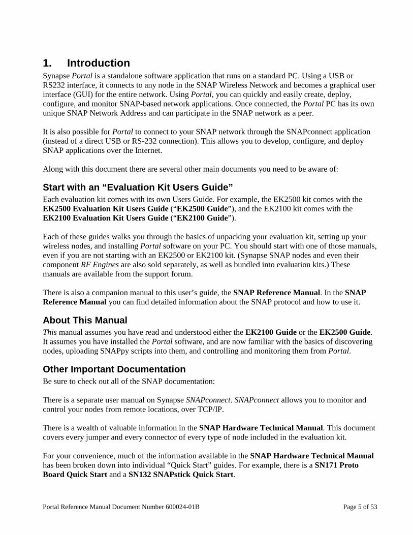
Start with an “Evaluation Kit Users Guide” Each evaluation kit comes with its own Users Guide. For example, the EK2500 kit comes with the EK2500 Evaluation Kit Users Guide (“EK2500 Guide”), and the EK2100 kit comes with the EK2100 Evaluation Kit Users Guide (“EK2100 Guide”). Each of these guides walks you through the basics of unpacking your evaluation kit, setting up your wireless nodes, and installing Portal software on your PC. You should start with one of those manuals, even if you are not starting with an EK2500 or EK2100 kit. (Synapse SNAP nodes and even their component RF Engines are also sold separately, as well as bundled into evaluation kits.) These manuals are available from the support forum. There is also a companion manual to this user’s guide, the SNAP Reference Manual. In the SNAP Reference Manual you can find detailed information about the SNAP protocol and how to use it.
About This Manual This manual assumes you have read and understood either the EK2100 Guide or the EK2500 Guide. It assumes you have installed the Portal software, and are now familiar with the basics of discovering nodes, uploading SNAPpy scripts into them, and controlling and monitoring them from Portal.
Other Important Documentation Be sure to check out all of the SNAP documentation: There is a separate user manual on Synapse SNAPconnect. SNAPconnect allows you to monitor and control your nodes from remote locations, over TCP/IP. There is a wealth of valuable information in the SNAP Hardware Technical Manual. This document covers every jumper and every connector of every type of node included in the evaluation kit. For your convenience, much of the information available in the SNAP Hardware Technical Manual has been broken down into individual “Quick Start” guides. For example, there is a SN171 Proto Board Quick Start and a SN132 SNAPstick Quick Start.

Page 6 of 53 Portal Reference Manual Document Number 600024-01B
There is also a dedicated support forum at http://forums.synapse-wireless.com. In the forum, you can see questions and answers posted by other users, as well as post your own questions. The forum also has examples and Application Notes, waiting to be downloaded. You can download the latest SNAP, Portal, and SNAPconnect software from the forum. You can also download the latest documentation from the forum, including the EK2500 and EK2100 guides. (You might want to do this if you bought standalone modules instead of buying a kit.)

Portal Reference Manual Document Number 600024-01B Page 7 of 53
2. The Portal Environment Portal is the desktop environment used to configure and deploy a SNAP network. It also provides a user-customizable interface to aid in developing your SNAPpy scripts. All of Portal’s windows can be resized, relocated, and enabled/disabled to configure the environment as needed. Starting Portal for the first time shows Portal’s default window configuration:
From this user interface you can connect to a SNAP bridge node and start viewing and configuring your SNAP network. The nodes in your network will be displayed in the Node Views window as they start responding to queries made by Portal. Selecting a node by clicking on it in the Node Views window will display detailed information about that node over in the Node Info window. Finally, the Event Log window displays event message about things that have occurred in the system and in the SNAP network. The remainder of this document is a reference guide to all of the Portal GUI elements. Each of Portal’s windows, toolbars, and options will be described in the next sections. For a more tutorial-like introduction to Portal, please see the EK2100 or EK2500 Users Guide.
Main Toolbar
Node Views Window Node Info Window
Event Log Window

Page 8 of 53 Portal Reference Manual Document Number 600024-01B
3. SNAP Node Views The starting point for managing SNAP nodes is the Node Views tab. If this window is not already open, you can click on View, then choose Node Views window. Alternatively, you can click on the icon on the toolbar. You will notice that the Node Views window has its own toolbar.
The Node Views tabbed window lets you look at your nodes in four different ways:
• Report View • Icon View • List View • Tree View
These four options provide different views of the same network information. Click on the Change to Report View button in the Node Views toolbar (not the main toolbar). Several columns of information are shown about each node found.
The Node column shows an icon and a name for each node. Both the icon and name can be changed by the user. What you see here are just the default icons.
is used within Portal to generically represent any SNAP node.
is used within the Portal user interface to represent Portal itself. (Remember, Portal is able to participate in the network as if it were a wireless node.)

Portal Reference Manual Document Number 600024-01B Page 9 of 53
The name for the node is assigned when the node is first discovered, and can come from three possible sources:
• As of version 2.1, it is possible to assign a name to a node • If you don’t give a node a name, it will use the name of any loaded script • If no name given and no script loaded, Portal will use “Node” as a base name
If more than one node would have the same name based on this arrangement, a trailing numeric identifier is appended to the base name so that all nodes have unique names. This is a Portal requirement. You can rename your units but each name must be unique. The Network Address column shows the three-byte Network Address for each node. The Network Address is simply the last three bytes of the node’s MAC Address, and is not user definable. The Device Image column shows the SNAPpy script/image loaded into the device. If there is no script loaded into the node, then this field is blank. Notice that this field tracks the currently loaded script. If you upload a different script into a node after it has been discovered/named, then this column can be different from the Node column. The Link Quality column shows a snapshot of the radio receive level. By default, it is expressed as a percentage, with 0% (-95 dBm) representing the weakest possible signal and 100% (-18 dBm) representing a maximum strength signal. (You can the system preferences to display the direct signal strength in the system preferences. See section 9 for more details.) It is important to understand three things about the displayed Link Quality: 1) Normally this field is not continuously refreshed – Portal does not “poll” nodes unless you tell it
to. You can use the Broadcast PING button to update the Link quality fields of all active units. There is also a Refresh button you can click on to force a refresh of a single node’s Link Quality. This button is on the Node Info toolbar, and is covered in section 4. Finally, there is a Watch Nodes button that essentially turns on automatic broadcast pings.
2) The value shown is based on the received signal strength of the most recent message from any other wireless node. It does not represent the signal strength between Portal and the node. (It is not an indication of the USB or RS232 quality between Portal and Portal’s bridge node.)
3) It is possible that at the time the Link Quality field was read from the unit, it had not yet received any radio messages from any other node. In this case, a value of 0 will be reported. This does not mean the unit has a faulty radio; it simply has not done any radio communications yet. This is most often seen with the node that is acting as a “bridge” for Portal, because Portal can be interacting with this directly attached node without necessarily generating any radio traffic.
The Device Type column shows one of the non-volatile (NV) configuration parameters of the unit. Device Type is simply a second string label that can be applied to a node. Unlike the Node Name, this label does not have to be unique, and is often used to show what job or role a node is filling. This parameter can also be read by SNAPpy scripts, allowing a single script to act differently on different nodes, simply by setting the Device Type of each node appropriately.
Page 10 of 53 Portal Reference Manual Document Number 600024-01B
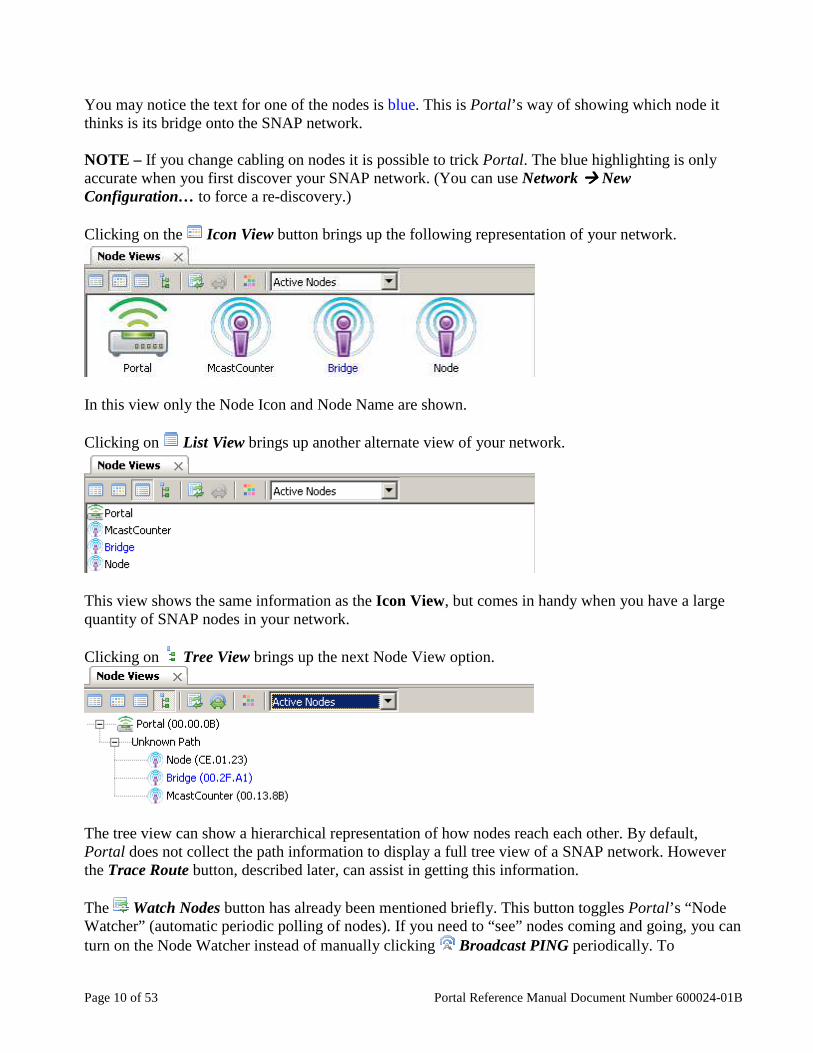
You may notice the text for one of the nodes is blue. This is Portal’s way of showing which node it thinks is its bridge onto the SNAP network. NOTE – If you change cabling on nodes it is possible to trick Portal. The blue highlighting is only accurate when you first discover your SNAP network. (You can use Network ���� New Configuration… to force a re-discovery.) Clicking on the Icon View button brings up the following representation of your network.
In this view only the Node Icon and Node Name are shown. Clicking on List View brings up another alternate view of your network.
This view shows the same information as the Icon View, but comes in handy when you have a large quantity of SNAP nodes in your network. Clicking on Tree View brings up the next Node View option.
The tree view can show a hierarchical representation of how nodes reach each other. By default, Portal does not collect the path information to display a full tree view of a SNAP network. However the Trace Route button, described later, can assist in getting this information. The Watch Nodes button has already been mentioned briefly. This button toggles Portal’s “Node Watcher” (automatic periodic polling of nodes). If you need to “see” nodes coming and going, you can turn on the Node Watcher instead of manually clicking Broadcast PING periodically. To
Portal Reference Manual Document Number 600024-01B Page 11 of 53
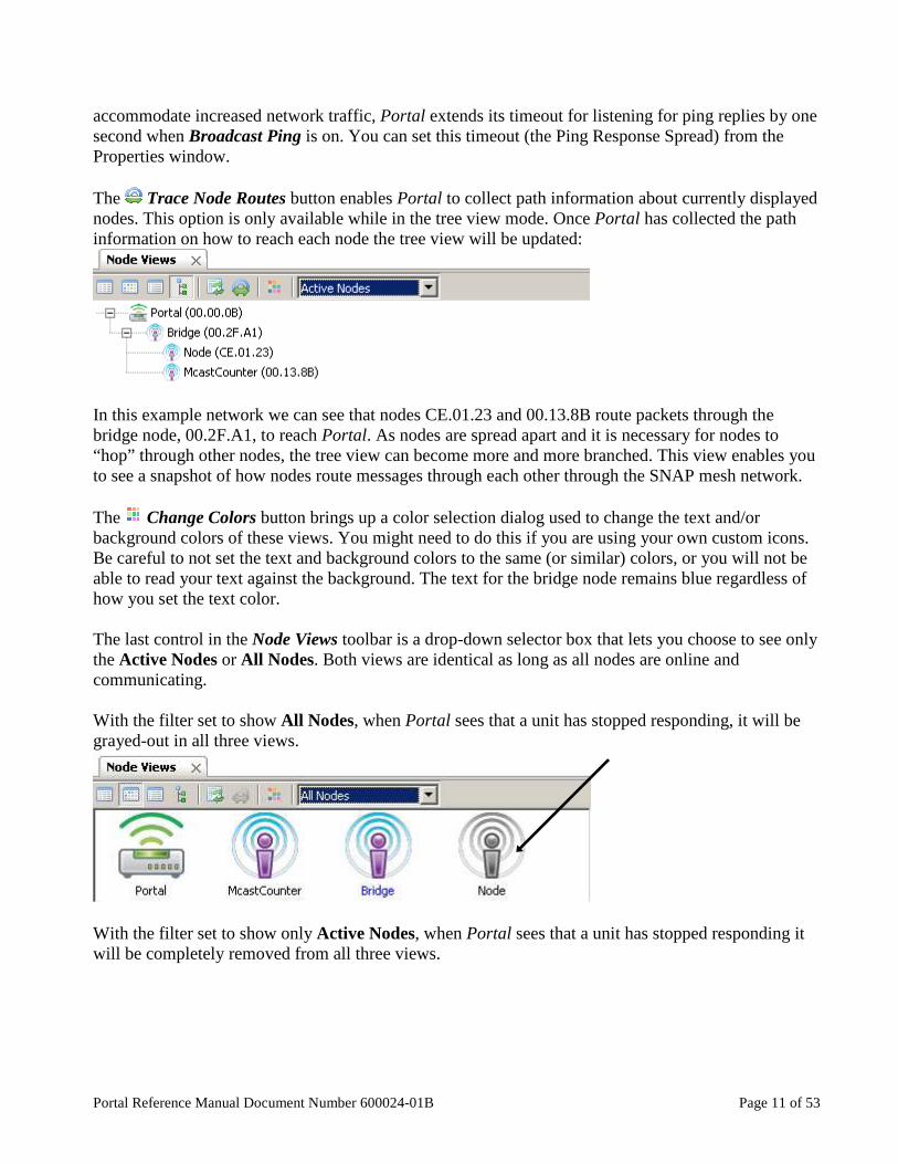
accommodate increased network traffic, Portal extends its timeout for listening for ping replies by one second when Broadcast Ping is on. You can set this timeout (the Ping Response Spread) from the Properties window. The Trace Node Routes button enables Portal to collect path information about currently displayed nodes. This option is only available while in the tree view mode. Once Portal has collected the path information on how to reach each node the tree view will be updated:
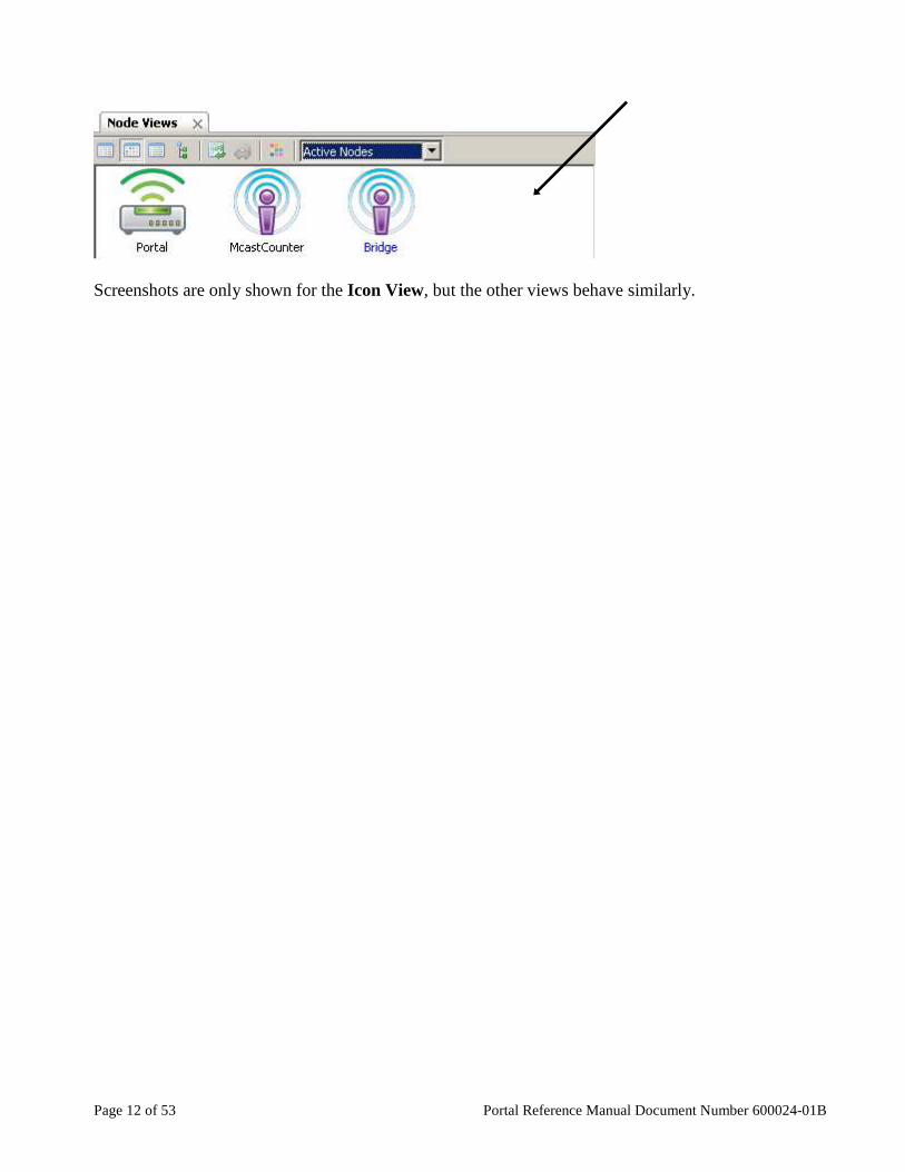
In this example network we can see that nodes CE.01.23 and 00.13.8B route packets through the bridge node, 00.2F.A1, to reach Portal. As nodes are spread apart and it is necessary for nodes to “hop” through other nodes, the tree view can become more and more branched. This view enables you to see a snapshot of how nodes route messages through each other through the SNAP mesh network. The Change Colors button brings up a color selection dialog used to change the text and/or background colors of these views. You might need to do this if you are using your own custom icons. Be careful to not set the text and background colors to the same (or similar) colors, or you will not be able to read your text against the background. The text for the bridge node remains blue regardless of how you set the text color. The last control in the Node Views toolbar is a drop-down selector box that lets you choose to see only the Active Nodes or All Nodes. Both views are identical as long as all nodes are online and communicating. With the filter set to show All Nodes, when Portal sees that a unit has stopped responding, it will be grayed-out in all three views.
With the filter set to show only Active Nodes, when Portal sees that a unit has stopped responding it will be completely removed from all three views.
Page 12 of 53 Portal Reference Manual Document Number 600024-01B
Screenshots are only shown for the Icon View, but the other views behave similarly.
Portal Reference Manual Document Number 600024-01B Page 13 of 53
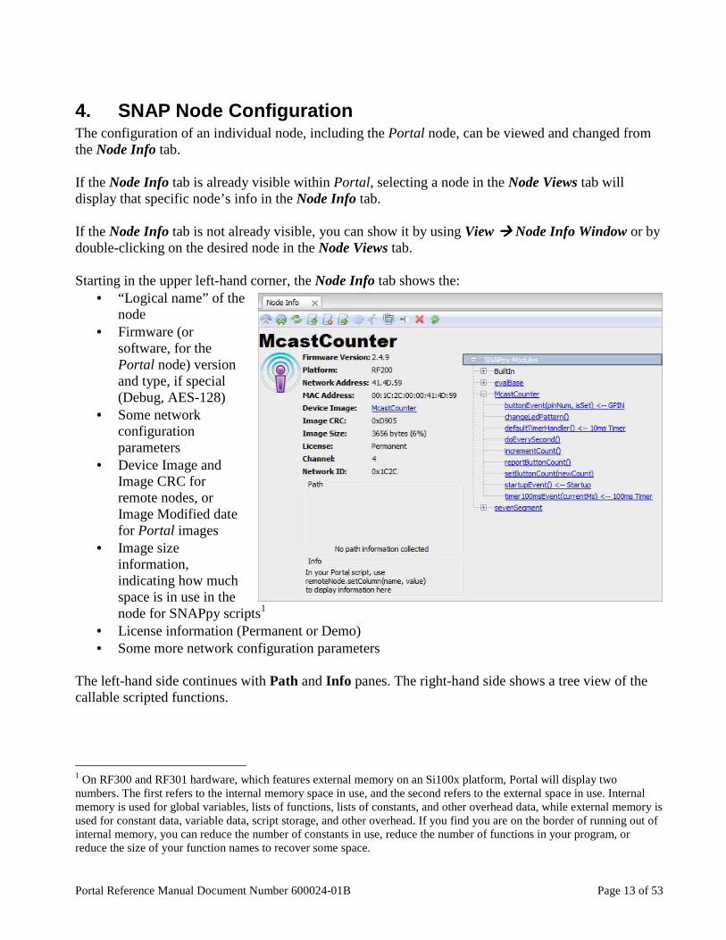
4. SNAP Node Configuration The configuration of an individual node, including the Portal node, can be viewed and changed from the Node Info tab. If the Node Info tab is already visible within Portal, selecting a node in the Node Views tab will display that specific node’s info in the Node Info tab. If the Node Info tab is not already visible, you can show it by using View ���� Node Info Window or by double-clicking on the desired node in the Node Views tab. Starting in the upper left-hand corner, the Node Info tab shows the:
• “Logical name” of the node
• Firmware (or software, for the Portal node) version and type, if special (Debug, AES-128)
• Some network configuration parameters
• Device Image and Image CRC for remote nodes, or Image Modified date for Portal images
• Image size information, indicating how much space is in use in the node for SNAPpy scripts1
• License information (Permanent or Demo) • Some more network configuration parameters
The left-hand side continues with Path and Info panes. The right-hand side shows a tree view of the callable scripted functions.
1 On RF300 and RF301 hardware, which features external memory on an Si100x platform, Portal will display two numbers. The first refers to the internal memory space in use, and the second refers to the external space in use. Internal memory is used for global variables, lists of functions, lists of constants, and other overhead data, while external memory is used for constant data, variable data, script storage, and other overhead. If you find you are on the border of running out of internal memory, you can reduce the number of constants in use, reduce the number of functions in your program, or reduce the size of your function names to recover some space.
Page 14 of 53 Portal Reference Manual Document Number 600024-01B
Network Configuration Parameters There are four network configuration parameters: Network Address, MAC Address, Channel, and Network ID . SNAP MAC addresses are standard 64-bit IEEE MAC addresses. MAC addresses are assigned to the node at the factory. The Network Address is the three-byte identifier that is actually used by the SNAP wireless protocol. It matches the last three bytes of the eight-byte MAC address. There are 16 allotted Channels for Synapse products. In the 2.4 GHz band used under the 802.15.4 specification, each channel maps to a particular specification channel. For nodes in the 900 MHz range these are logical channels, each of which uses a range of 25 frequencies. See the SNAP Reference Manual for more details on the frequencies used by each of these configurations. The SNAP Network ID can be thought of as a “logical channel.” This 16-bit integer may be assigned any hexadecimal value from 0x0001 through 0xFFFE. Devices in a SNAP network must share both the same Channel and same Network ID in order to communicate. This allows multiple SNAP networks to share the same channel if required, although it is preferred to place independent networks on separate physical channels to reduce collisions.
Node Info – Tasks Pane There are ten toolbar options in this pane. (Not all are active for the Portal node.)
• Ping – poll a node for connectivity. • Traceroute – collect path information to the node. • Refresh – poll a unit for the values shown in the Node Info tab. • Upload SNAPpy Image – program a node with a new script. (This button is labeled Change
Portal Base File for the Portal node.) • Erase SNAPpy Image – remove previously loaded script. (This button is labeled Clear
Portal Base File for the Portal node.) • Export SNAPpy Image – export a SNAPpy image as a .SPY file. • Change Configuration Parameters – more on this below. • Intercept STDOUT – divert the node’s script output to Portal. • Change Icon – substitute an alternate PNG graphic file as the node’s icon. • Rename Node – replace the node’s current logical name. • Remove Node – remove the node from the various Node Views. • Reboot Node – reboot the node.
Ping Clicking on this action causes Portal to make a quick connectivity test to the selected node. Observe the Event Log for confirmation of Ping activity. The Ping action is not available for the Portal node.
Portal Reference Manual Document Number 600024-01B Page 15 of 53
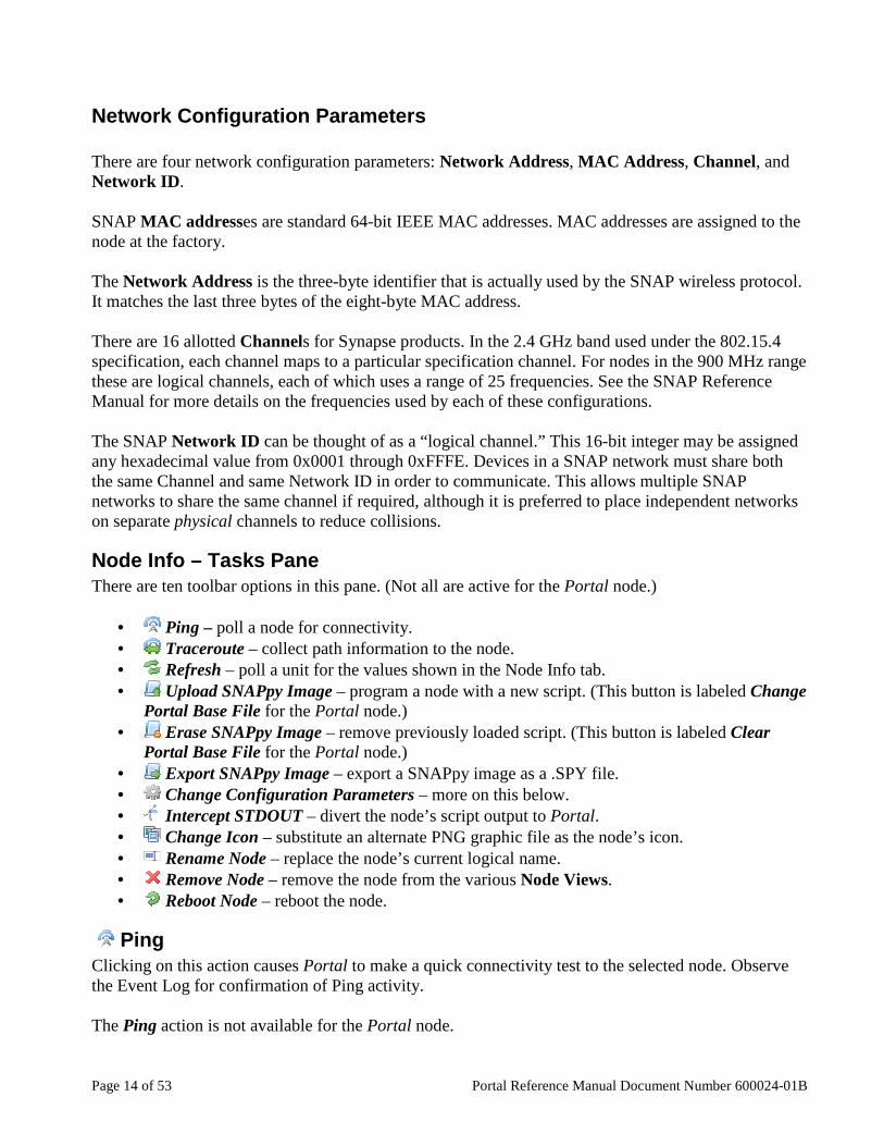
A Broadcast Ping command (seen by all nodes) is also available in the Portal toolbar, here:
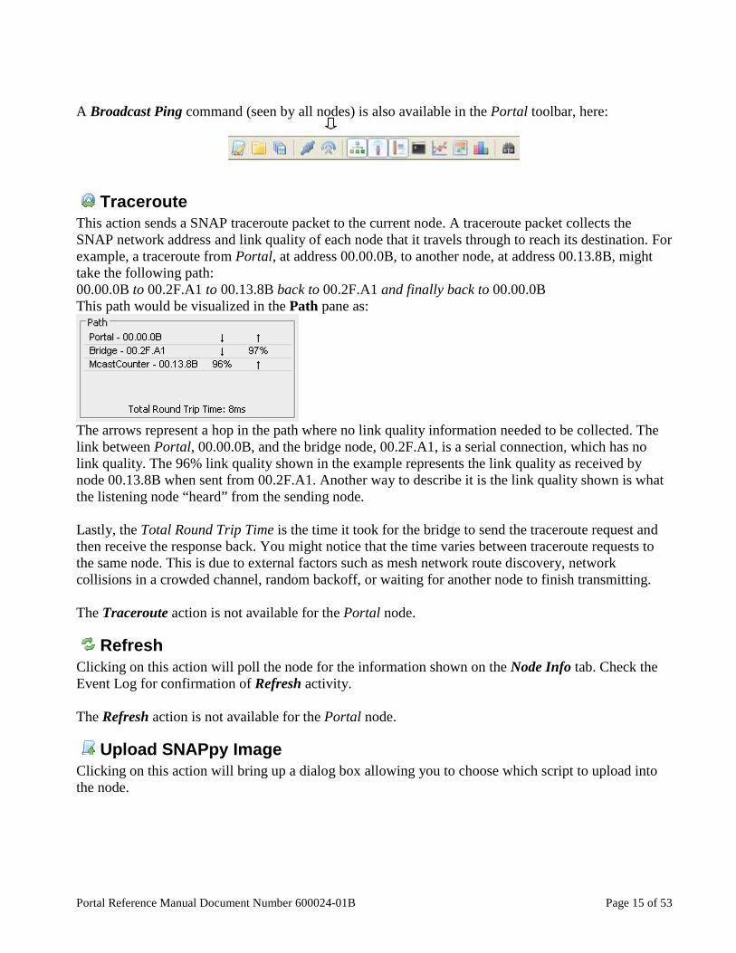
Traceroute This action sends a SNAP traceroute packet to the current node. A traceroute packet collects the SNAP network address and link quality of each node that it travels through to reach its destination. For example, a traceroute from Portal, at address 00.00.0B, to another node, at address 00.13.8B, might take the following path: 00.00.0B to 00.2F.A1 to 00.13.8B back to 00.2F.A1 and finally back to 00.00.0B This path would be visualized in the Path pane as:
The arrows represent a hop in the path where no link quality information needed to be collected. The link between Portal, 00.00.0B, and the bridge node, 00.2F.A1, is a serial connection, which has no link quality. The 96% link quality shown in the example represents the link quality as received by node 00.13.8B when sent from 00.2F.A1. Another way to describe it is the link quality shown is what the listening node “heard” from the sending node. Lastly, the Total Round Trip Time is the time it took for the bridge to send the traceroute request and then receive the response back. You might notice that the time varies between traceroute requests to the same node. This is due to external factors such as mesh network route discovery, network collisions in a crowded channel, random backoff, or waiting for another node to finish transmitting. The Traceroute action is not available for the Portal node.
Refresh Clicking on this action will poll the node for the information shown on the Node Info tab. Check the Event Log for confirmation of Refresh activity. The Refresh action is not available for the Portal node.
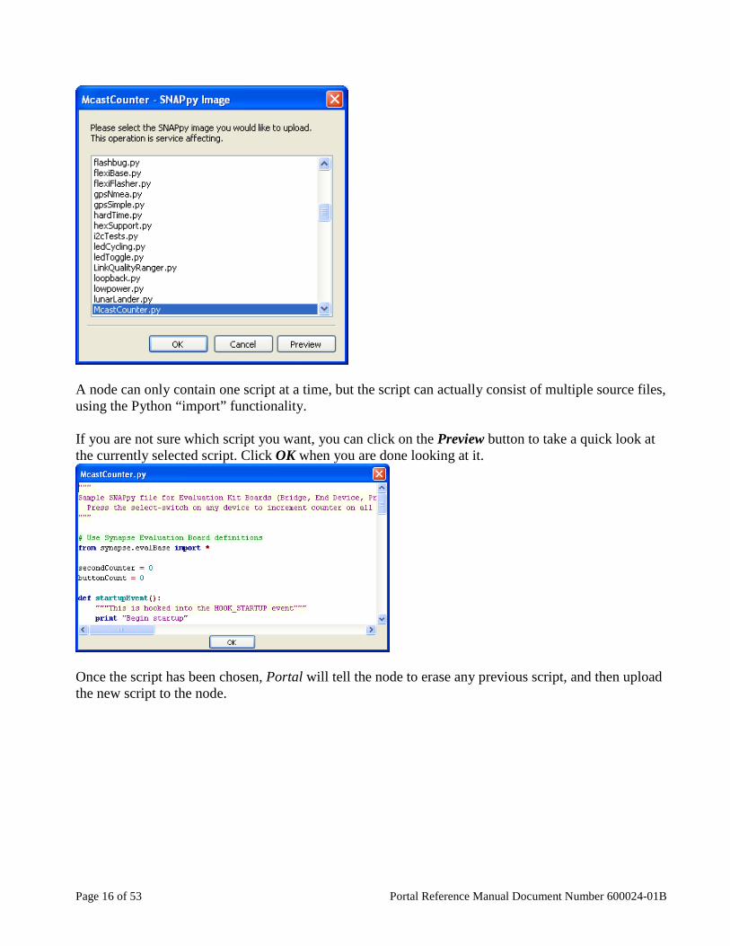
Upload SNAPpy Image Clicking on this action will bring up a dialog box allowing you to choose which script to upload into the node.
Page 16 of 53 Portal Reference Manual Document Number 600024-01B
A node can only contain one script at a time, but the script can actually consist of multiple source files, using the Python “import” functionality. If you are not sure which script you want, you can click on the Preview button to take a quick look at the currently selected script. Click OK when you are done looking at it.
Once the script has been chosen, Portal will tell the node to erase any previous script, and then upload the new script to the node.

Portal Reference Manual Document Number 600024-01B Page 17 of 53
When the entire script has been uploaded to the node Portal will automatically reboot the node, which in turn will cause the node to execute any script code contained within the HOOK_STARTUP event handler of that script. If you click on the name of a script within the Node Info window, an editor window containing that script will be opened for you. For the Portal node, this action is named Change Portal Base File. The Portal node is not restricted to SNAPpy scripts, and can run any Python script. Therefore the button opens a standard Windows dialog allowing you to browse to the Python script of your choice. For more information about SNAPpy scripting, please consult the SNAP Reference Guide.
Erase SNAPpy Image Clicking on this action will erase any currently loaded (and running) script from the selected node. NOTE – You do not have to manually erase a previous script to load a new one. Portal will do this for you. This button has been added so that misbehaving scripts can be shut down while you work on making corrections to them. For the Portal node, this action is named Clear Portal Base File.
Export SNAPpy Image This toolbar option allows you to export the SNAPpy script as a SNAPpy Export (.SPY) file. The .SPY files are used to save the current local copy of the script as a compiled script ready to upload to a node. For example, SNAPconnect cannot upload .py files because it requires the scripts to already be compiled. This option allows you to create the necessary .SPY file for SNAPconnect to upload to your nodes. Another use for the .SPY files is if you want to provide a script to another user of Portal without giving them the source code. The Export SNAPpy Image action is not available for the Portal node, because Portal can run Python scripts that are not valid in another node.

Page 18 of 53 Portal Reference Manual Document Number 600024-01B
Change Configuration Parameters Clicking on this task will bring up the following (tabbed) dialog box:
From this dialog box, you can view and edit the Configuration Parameters of the current SNAP Node. Configuration Parameters are also known as Non-Volatile Parameters, or NV Parameters, and they are described in detail in the SNAP Reference Manual. You can see the different NV Parameters broken down by category by clicking on one of the six named tabs within the dialog box. The Network tab lists parameters relating to general radio operations. The Device tab lists parameters relating to node “identity,” and some hardware features. The Multi-cast tab lists parameters relating to multicast communications. The UART tab lists parameters relating to the buffering of data received from the system’s universal asynchronous receiver/transmitter(s) for serial communications.

Portal Reference Manual Document Number 600024-01B Page 19 of 53
The Mesh tab lists parameters relating to the mesh routing capabilities of the node. Synapse nodes communicate with each other using mesh routing. This means that any unit can communicate with any other unit (they are all logical peers within the mesh), even though in some cases units that are out of radio range of each other might have to pass messages through intermediate nodes to do so. Only units that are within radio range of each other can communicate directly (physical peers). The necessary “route discovery” and “packet forwarding” necessary to make this work are all done automatically by the node. There are several Mesh Routing Timeouts. The default values should cover most network topologies. Be careful if changing these values on remote nodes: you could make it impossible to communicate with the node remotely. Contact Synapse Customer Support for assistance with tuning these timeout parameters. There are also several “non-timeout” parameters. Refer to the SNAP Reference Manual for information about using them. The Security tab lists parameters relating to encryption. Specify an Encryption Type of 0 for no encryption, 1 for AES-128 encryption, or 2 for Basic encryption. If encryption is enabled, the Encryption Key must be exactly 16 characters long, and can be any combination of text string and hexadecimal values. NOTE – Not all nodes support AES-128 encryption. This is determined by the SNAP firmware currently loaded into the node. However all nodes running firmware version 2.4 or newer will have Basic encryption available. To change one or more of the editable fields, just type the replacement value(s) in before clicking on OK. The new values will be sent to the node and stored. The Change Configuration Parameters action is not available for the Portal node.
Intercept STDOUT Script output (from “print” statements) normally goes to the “data sink” specified by the script itself. For example, the script might be outputting text to serial port 2. For testing purposes, it is sometimes handy to “intercept” the script output from the node (which might be remotely located), and display it within Portal instead. Clicking on this action will send the necessary commands to the node to accomplish this. The intercepted text will appear in the Portal Event Log.

Page 20 of 53 Portal Reference Manual Document Number 600024-01B
In the above example, the script did a print “hello, world!” The node name (“Lighter”) was pre-pended by Portal, providing an easy way to see which node printed the text. You must specify which types of messages you want your node to redirect to Portal using the Preferences window available from the File menu in Portal. You can have your nodes send STDOUT, error messages, both, or neither to the Portal log. If you have both the Intercept STDOUT and Intercept ERROR checkboxes unchecked on the Preferences window, no output from the node will be redirected to the Portal log. The Intercept STDOUT action is not available for the Portal node.
Change Icon You can replace the default icon Portal uses to represent each node with your own 60x60 PNG files. This might be used to make it easier to track which nodes are serving what purpose. The graphic is only associated with the node while Portal is aware of the node. If you remove the node from the network, you will need to reassign your graphic icon to it.
Rename Node The default “logical name” for a node with no name provided by the user, and no script loaded is “Node” (for the first one found) or “NodeX” (for subsequent nodes), where “X” is a number (starting at 2) that represents the order in which Portal discovered the nodes. The Rename Node action allows you to choose your own name for a node, instead of using the default name assigned by Portal. This “given name” is stored in the node itself (in NV Parameter 8), and will automatically be reported by Portal (instead of “Node”) if Portal re-discovers the node in the future. Node names may not contain spaces, punctuation or any special characters other than underscore. You should not specify a node names longer than 64 characters.
Remove Node Clicking on this action will remove the node from Portal, including removing the node from the Node Views. Be aware that if the node really does still exist, it will be re-discovered by Portal on the next broadcast ping. The Remove Node action is not available for the Portal node.
Reboot Node Clicking on this action will bring up the following prompt.

Portal Reference Manual Document Number 600024-01B Page 21 of 53
If you really do want to reboot (restart) the node, select Yes, otherwise select No. The Reboot Node action is not available for the Portal node.
Node Info – “SNAPpy Scripts” Section The right hand side of the Node Info tab shows a tree view of all the callable functions within that node.
The BuiltIn functions represent the core SNAPpy feature set, and are functions that can be called from Portal even when no user script has been uploaded into the node. These same functions are also always available for use within scripts. Refer to the SNAP Reference Guide for details on these built-in SNAPpy functions.
Page 22 of 53 Portal Reference Manual Document Number 600024-01B
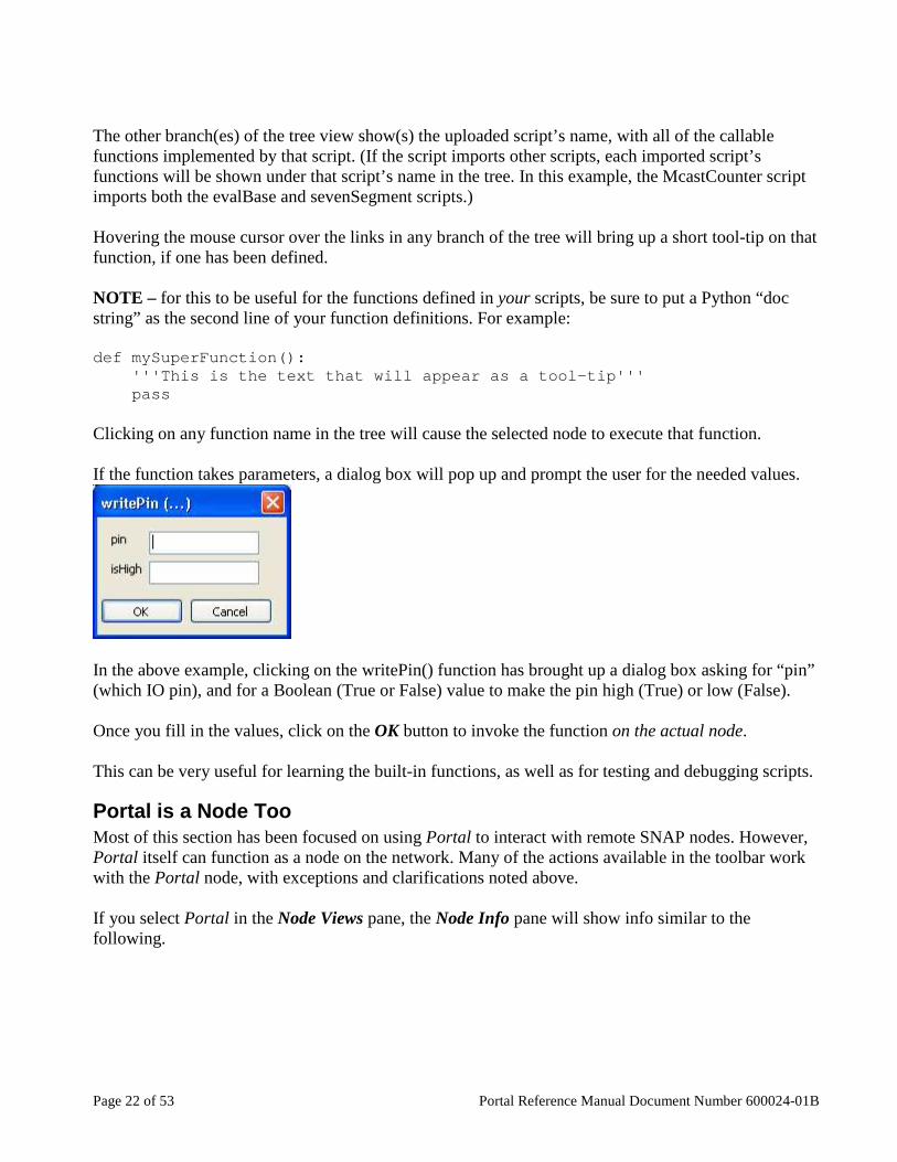
The other branch(es) of the tree view show(s) the uploaded script’s name, with all of the callable functions implemented by that script. (If the script imports other scripts, each imported script’s functions will be shown under that script’s name in the tree. In this example, the McastCounter script imports both the evalBase and sevenSegment scripts.) Hovering the mouse cursor over the links in any branch of the tree will bring up a short tool-tip on that function, if one has been defined. NOTE – for this to be useful for the functions defined in your scripts, be sure to put a Python “doc string” as the second line of your function definitions. For example: def mySuperFunction(): '''This is the text that will appear as a tool- tip''' pass Clicking on any function name in the tree will cause the selected node to execute that function. If the function takes parameters, a dialog box will pop up and prompt the user for the needed values.
In the above example, clicking on the writePin() function has brought up a dialog box asking for “pin” (which IO pin), and for a Boolean (True or False) value to make the pin high (True) or low (False). Once you fill in the values, click on the OK button to invoke the function on the actual node. This can be very useful for learning the built-in functions, as well as for testing and debugging scripts.
Portal is a Node Too Most of this section has been focused on using Portal to interact with remote SNAP nodes. However, Portal itself can function as a node on the network. Many of the actions available in the toolbar work with the Portal node, with exceptions and clarifications noted above. If you select Portal in the Node Views pane, the Node Info pane will show info similar to the following.

Portal Reference Manual Document Number 600024-01B Page 23 of 53
If a Portal script has been loaded, you will see it in the Portal Modules function tree as well. You can invoke any functions defined in that script by clicking on them, just as you can with the functions defined in the remote SNAP nodes.

Page 24 of 53 Portal Reference Manual Document Number 600024-01B
5. Portal Tools The main toolbar provides quick access to Portal’s tabbed windows. These windows can be shown, hidden, or rearranged to suit a variety of operational modes. Some of the toolbar buttons invoke immediate commands instead of opening new tabbed windows.
New Script Clicking on this button will open a new Edit Window containing a new (empty) source file.
The default name of the script will be “NewScriptX” where “X” is a trailing number to enforce uniqueness. The Edit Window is described in section 6.
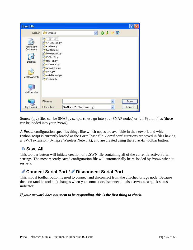
Open File Clicking on this button will bring up a file chooser dialog, from which you can select a previously saved source or Portal configuration file.
Portal Reference Manual Document Number 600024-01B Page 25 of 53
Source (.py) files can be SNAPpy scripts (these go into your SNAP nodes) or full Python files (these can be loaded into your Portal). A Portal configuration specifies things like which nodes are available in the network and which Python script is currently loaded as the Portal base file. Portal configurations are saved in files having a .SWN extension (Synapse Wireless Network), and are created using the Save All toolbar button.
Save All This toolbar button will initiate creation of a .SWN file containing all of the currently active Portal settings. The most recently saved configuration file will automatically be re-loaded by Portal when it restarts.
Connect Serial Port / Disconnect Serial Port This modal toolbar button is used to connect and disconnect from the attached bridge node. Because the icon (and its tool-tip) changes when you connect or disconnect, it also serves as a quick status indicator. If your network does not seem to be responding, this is the first thing to check.
Page 26 of 53 Portal Reference Manual Document Number 600024-01B
Broadcast Ping Clicking on this toolbar button will cause Portal to broadcast a special “answer if you hear me” message to all nodes. When the nodes answer, any nodes that Portal did not already know about will be individually queried for additional information. You might use this button if you just added one or more new nodes to your network. Broadcast Ping will only find nodes using the same channel and network ID as your bridge node.
Node Views This tab provides a graphical display of the nodes in Portal’s internal device directory. Internally, Portal indexes all nodes by network address. When a new network address is discovered, a corresponding icon in the Node Map will be created. Deleting a node (select on the node and then click Remove Node from the Node Info tab) removes the device from Portal’s internal database. This removes all knowledge of the device from Portal. If the device is subsequently re-discovered, usually via a ping, it will reappear in the Node Map. The Node Views pane is covered in section 12.
Node Info The Node Info tab provides node information, a mini-toolbar for common tasks, and SNAPpy script information about the currently selected node. (Refer to section 13).
Event Log The Event Log captures real-time event history for Portal. All network-affecting activity is recorded here. Log entries are time-stamped to a 1-second resolution. Events Captured Include:
• Configuration save/load • Script STDOUT (print statements, errors) • Status messages • RPC communication messages
Command Line The Command Line window provides interactive access to Portal’s Python-based scripting engine. Using this tool, you can invoke the Device API on all discovered and active devices. This is useful for testing and debugging commands interactively before incorporating them into Portal scripts. Most of what can be done through the command line can also be done through the other parts of the GUI. For example, you can type the command: rpc(‘\x01\x02\x03’, ‘reboot’) … or you can just click on the node’s reboot() function in the Node Info tree.
Portal Reference Manual Document Number 600024-01B Page 27 of 53
Within the Command Line pane, you can use the up and down cursor arrows to re-select previously executed commands. Position the cursor on a previously executed command and press the <Enter> key, and it will be re-displayed (but not executed yet) at the bottom of the Command Line window. You can then edit the recalled command (using the left and right cursor keys to move the cursor horizontally within the command). When the command line has been edited to your liking, press the <Enter> key again to execute it. To re-execute the most recently executed command as-is (no changes), just press the keys <Up>, <Enter>, <Enter>. The first <Enter> chooses the command for editing, and the second <Enter> executes it. Within the Command Line window, you can type shell.help() to learn more of the tricks the Command Line window supports.
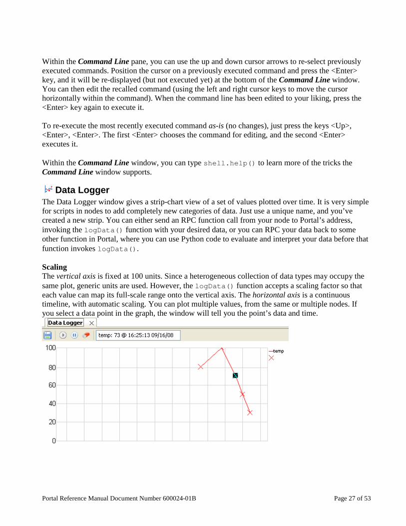
Data Logger The Data Logger window gives a strip-chart view of a set of values plotted over time. It is very simple for scripts in nodes to add completely new categories of data. Just use a unique name, and you’ve created a new strip. You can either send an RPC function call from your node to Portal’s address, invoking the logData() function with your desired data, or you can RPC your data back to some other function in Portal, where you can use Python code to evaluate and interpret your data before that function invokes logData() . Scaling The vertical axis is fixed at 100 units. Since a heterogeneous collection of data types may occupy the same plot, generic units are used. However, the logData() function accepts a scaling factor so that each value can map its full-scale range onto the vertical axis. The horizontal axis is a continuous timeline, with automatic scaling. You can plot multiple values, from the same or multiple nodes. If you select a data point in the graph, the window will tell you the point’s data and time.
Page 28 of 53 Portal Reference Manual Document Number 600024-01B
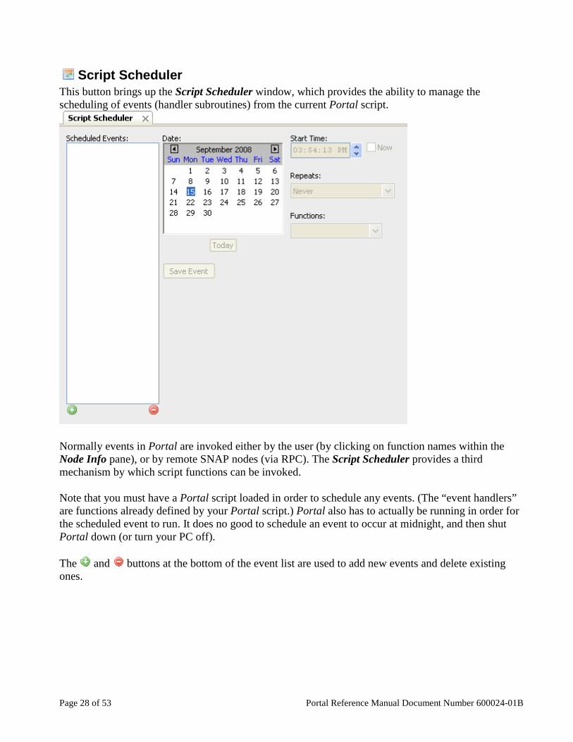
Script Scheduler This button brings up the Script Scheduler window, which provides the ability to manage the scheduling of events (handler subroutines) from the current Portal script.
Normally events in Portal are invoked either by the user (by clicking on function names within the Node Info pane), or by remote SNAP nodes (via RPC). The Script Scheduler provides a third mechanism by which script functions can be invoked. Note that you must have a Portal script loaded in order to schedule any events. (The “event handlers” are functions already defined by your Portal script.) Portal also has to actually be running in order for the scheduled event to run. It does no good to schedule an event to occur at midnight, and then shut Portal down (or turn your PC off). The and buttons at the bottom of the event list are used to add new events and delete existing ones.
Portal Reference Manual Document Number 600024-01B Page 29 of 53
If you click on the add button, you will be prompted to provide a name for the event.
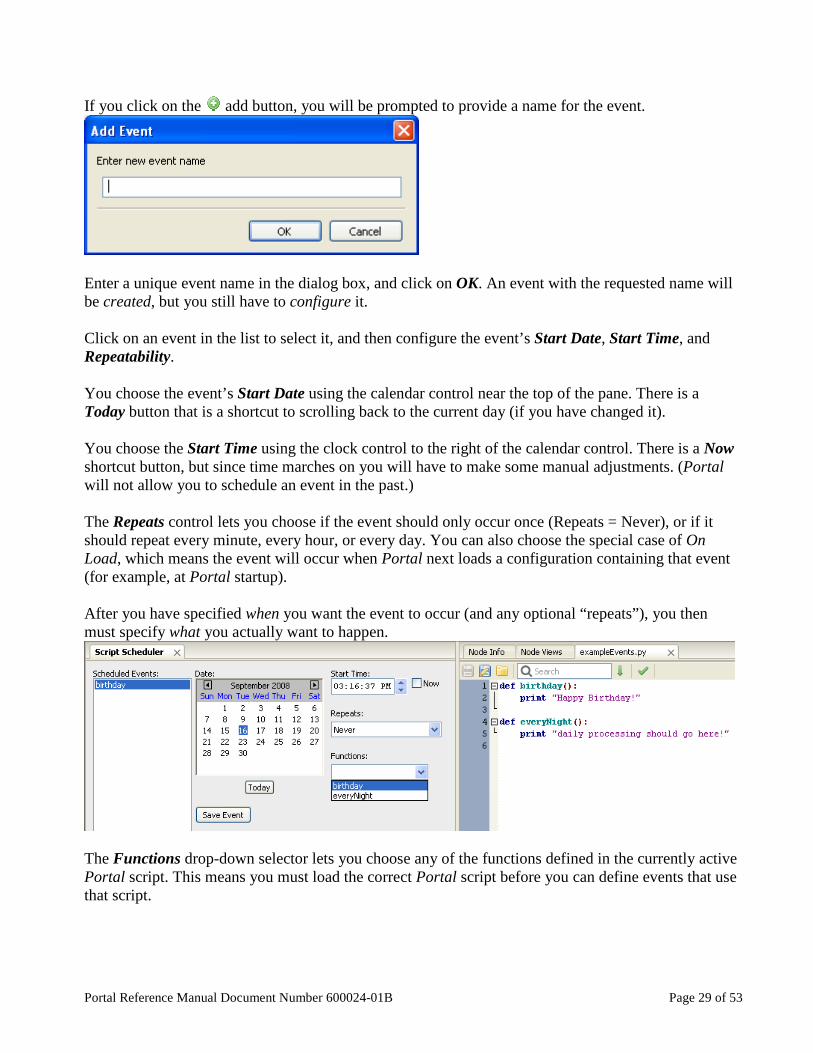
Enter a unique event name in the dialog box, and click on OK. An event with the requested name will be created, but you still have to configure it. Click on an event in the list to select it, and then configure the event’s Start Date, Start Time, and Repeatability. You choose the event’s Start Date using the calendar control near the top of the pane. There is a Today button that is a shortcut to scrolling back to the current day (if you have changed it). You choose the Start Time using the clock control to the right of the calendar control. There is a Now shortcut button, but since time marches on you will have to make some manual adjustments. (Portal will not allow you to schedule an event in the past.) The Repeats control lets you choose if the event should only occur once (Repeats = Never), or if it should repeat every minute, every hour, or every day. You can also choose the special case of On Load, which means the event will occur when Portal next loads a configuration containing that event (for example, at Portal startup). After you have specified when you want the event to occur (and any optional “repeats”), you then must specify what you actually want to happen.
The Functions drop-down selector lets you choose any of the functions defined in the currently active Portal script. This means you must load the correct Portal script before you can define events that use that script.

Page 30 of 53 Portal Reference Manual Document Number 600024-01B
In the screenshot above, both the Script Scheduler pane and a Script Editor pane are shown. You can see the correlation between the Functions field and the script source code. When the event has been configured like you want, be sure to press the Save Event button. If you change your script after setting a scheduled event in Portal, the script scheduler will continue to run a cached version of the script until the next time Portal is started. To ensure the latest version of your script will run on schedule, be sure to restart Portal after making the change.
Channel Analyzer Clicking this button will open the Channel Analyzer pane within Portal.
Performing a channel analysis (energy detection scan) consumes significant resources on your bridge node, so the function is only performed on demand. Performance of other functions within Portal (such as uploading scripts to a node or running a Portal script) may be significantly affected while the Channel Analyzer is running. It may be best to pause the analyzer while you perform other functions. Like many panes, the Channel Analyzer pane has its own mini-toolbar.
• The Start button begins continuous channel scanning. • Once started, the Stop button can be used to stop it.

Portal Reference Manual Document Number 600024-01B Page 31 of 53
• The Packets Received indicator show the number of energy detection packets received from the bridge.
• The Clear Values button can be used to erase any existing data and start a fresh plot. • The Save Graph button can be used to save the currently graphed data as a graphic. • The Channel Help button brings up a list of channels with an indication of how clear each
channel is. This can help you choose the best channel for your nodes based on radio traffic in your environment.
• A dBm Floor slider lets you choose a cutoff value for the graphed data. This lets you ignore low-level signals and focus on stronger ones.
Here is a screenshot taken from a system while scanning was actually in progress. Note that you may not have as much active traffic as in the example shown. If you are using nodes in the 900 MHz range, the Channel Analyzer will show 66 frequencies rather than the 16 channels. See the SNAP Reference Manual for information about how frequencies map to channels on 900 MHz SNAP nodes.
The colored bars in the chart provide three pieces of information simultaneously:
1) The horizontal position of each bar tells you the channel on which the signal was seen. 2) The vertical position tells you the signal strength seen for that signal.

Page 32 of 53 Portal Reference Manual Document Number 600024-01B
3) The color of each bar tells you the number of times a signal of that level has been seen (in % form). A color legend near the top of the pane shows you the scaling.
In the example above, you can see that the strongest signals have been detected on channel 12 (around -48 dBm), but that the most frequently seen signal is on channel 6 (at around -87 dBm). Note that the Channel Analyzer takes “live” readings, and can only detect signals from nodes that are actually powered on, awake, and communicating at the time of the scan. You can restart your graph at any time with the Clear Values button, and you can save as many graphs as you want using the Save Graph button. Be sure to use the Stop button when you are done. This will give your bridge node more time to handle other network traffic. Clicking on Channel Help brings up a dialog similar to the following:
From the example chart, you would expect that channel 1 or channel 15 would be the best choice for newly deployed nodes (as they are relatively quiet right now), followed by channels 0 and 2. You can click column headers to sort the list to quickly find the weakest signal seen (most clear channel) or strongest signal seen (most crowded channel).
Find Nodes Clicking on this button will bring up the following interactive dialog:
Portal Reference Manual Document Number 600024-01B Page 33 of 53
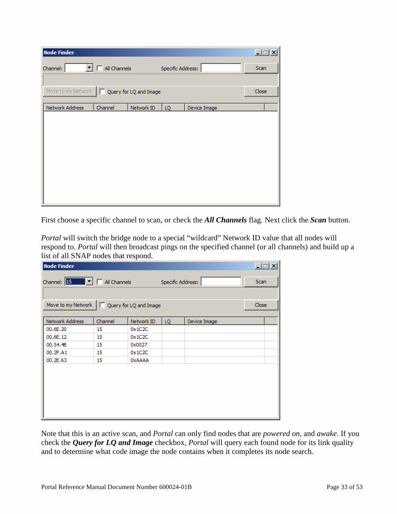
First choose a specific channel to scan, or check the All Channels flag. Next click the Scan button. Portal will switch the bridge node to a special “wildcard” Network ID value that all nodes will respond to. Portal will then broadcast pings on the specified channel (or all channels) and build up a list of all SNAP nodes that respond.
Note that this is an active scan, and Portal can only find nodes that are powered on, and awake. If you check the Query for LQ and Image checkbox, Portal will query each found node for its link quality and to determine what code image the node contains when it completes its node search.

Page 34 of 53 Portal Reference Manual Document Number 600024-01B
In the example shown here, five nodes were found on Channel 15, on three separate networks. Because the broadcast ping process uses (unacknowledged) broadcast messages, some nodes may not respond. You may have to hit the Scan button more than once to find the node you are looking for. If the Node Finder locates a node on a different channel or using a different network ID than Portal’s bridge node is using, you can select the node within the list and click the Move to my Network button. Portal will then command the node to change channel and/or network ID as needed. Press the Close button to close this dialog and resume normal Portal operations. If you are looking for a specific node with a known network address, you can use the Specific Address textbox to enter its network address. This allows you to search for that specific node and move it to your current network if needed, instead of getting a list of all nodes.

Portal Reference Manual Document Number 600024-01B Page 35 of 53
Rearranging Windows The tabbed windows in Portal can be dragged and repositioned on the screen. To do this, press and hold the left mouse button while the cursor is positioned over the tab label you want to move. While holding the button down, drag the tab until you see a light blue “shadow” indicating a possible new position for the window. When you’ve found a suitable new position, release the mouse button and the move will be complete.
Window panes may be resized by clicking and dragging the horizontal and vertical borders separating them. If you have made changes to your window placement and sizing and wish to have Portal return to its default layout, select View ���� Rearrange to Default View and you will be returned to a view with the Node Views window on the left, the Node Info window on the right, and the Event Log window across the bottom of the screen.
Drag tab as shown to move windows

Page 36 of 53 Portal Reference Manual Document Number 600024-01B
6. Built-in Editor Portal includes a built-in code editor, making it an all-in-one solution. The code editor includes useful features such as line numbering, automatic indentation, code folding, and text auto completion2, making it easy to develop scripts that meet your needs. Note – If you already have a favorite editor, you can use it instead. There are several ways to open an editor pane:
• Click on a script name from the Node Info pane • Use the Open File button on the main toolbar • Use the New Script button on the main toolbar
Regardless of how you opened it, all the edit windows work the same way.
A mini-toolbar provides buttons to Save, Save As, and Open File. Next is a search window (<Ctrl-F> is a keyboard shortcut for this), and a Find Next button.
2 Auto completion of text requires that the synapse.BuiltIn.py file be present in your scripts directory. This file is present when Portal is installed, and you should no move, delete or rename it.
Portal Reference Manual Document Number 600024-01B Page 37 of 53
The Test SNAPpy Script button lets you validate SNAPpy scripts (only) before you try to upload them into a node. Starting in version 2.2 the platform and version can affect how a script is compiled for a node. When you click the button to compile the script, you will be prompted for the platform and version appropriate for your target SNAP node. For the version, enter the firmware version for your node (e.g., 2.4.9). Select the platform and the appropriate CPU. (The platform selected can will control which code is compiled in your script. It matches the Platform specified for the node. If you exclusively use the “default” platforms specified by Synapse Wireless, the CPU will automatically default for you. Refer to the platform selections listed in the platforms.py file included in the snappyImages\synapse directory for examples of the default platform values.) If you have opened a read-only file, a message on the toolbar will tell you so. You can perform a Save As to create a separate editable copy. This lets you start with an existing demo script and make your own custom variations. If you try to type characters into the edit window of a read-only file, Portal volunteers to save the file to a writable copy for you.
If you did not mean to be editing the read-only file, just click on No. If you do want to edit a copy of the original read-only file, click on Yes. The usual file dialog box will allow you to specify the new file name. The edit window will automatically switch to editing the newly created file.

Page 38 of 53 Portal Reference Manual Document Number 600024-01B
Be sure to Save your edits when you are done. Your new script can be uploaded into one or more SNAP nodes using the Upload Snappy Image button in the Node Info window.

Portal Reference Manual Document Number 600024-01B Page 39 of 53
7. Firmware Updates The Firmware Version is shown in the Node Info pane for each SNAP node in your network. Upgrading your devices to a newer version of SNAP is easy with Portal. Note – Upgrades use UART1 of the RF Engine (on engines with more than one UART). This means a connection to the second serial port (usually RS-232) of the device being upgraded is required. Note that the SNAPstick carrier does not support reprogramming. You must move the RF Engine from the SNAPstick to some other board (like the SN171 Proto Board) in order to upgrade that RF Engine’s firmware.
Obtaining Firmware Each new release of Portal includes the most current version of the SNAP firmware at the time of that Portal release. Intermediate “firmware only” updates may also be available on the Synapse Support Web Site: http://forums.synapse-wireless.com/ Look in the Latest Releases thread on the forum, under the Software Releases topic.
Installing new Firmware First make sure you have an RS232 connection to the device you are upgrading. This requires a connection to the DB9 connector on the Evaluation kit board, as the USB connection on that board connects to UART0, which is not supported for firmware upgrades. From Portal’s Options menu, select Firmware Upgrade… The following dialog box will display:
Portal will list the available COM ports on your system under the Port dropdown. Manually select the
correct COM port to which that your SNAP node is connected. (You may need to click the Scan button for Portal to locate your serial connection.) Select the Firmware Image to be used for the upgrade. Note that starting with version 2.1, there are now four types of firmware images from which to choose:

Page 40 of 53 Portal Reference Manual Document Number 600024-01B
• Firmware images with “debug” in the title have extra error checks to help debug user scripts and configurations. These extra diagnostic checks come at the expense of a slight decrease in speed and SNAPpy image space.
• Firmware images without “debug” in the title do not have these extra error checks, which allow them to run faster, and have more room for SNAPpy images.
• Firmware images with AES128 in their name have built-in support for AES-128 over-the-air encryption. These images are not included with Portal, but can be ordered separately from Synapse. (There is an additional charge for AES-128 support.)
• Firmware images without AES in the title do not support AES-128 encryption. The firmware image names also indicate the version of that firmware. For example, 2.4.10 is newer firmware than 2.4.6, and both are newer than 2.2.16. After choosing the correct firmware image to load, press the Upgrade button to begin. Follow the instructions given in the dialog, which may have you restart (power-cycle or reset) your device to complete the process.
New firmware will be sent to the SNAP node over the serial connection.
Portal Reference Manual Document Number 600024-01B Page 41 of 53
Choose Yes to download the same image into another SNAP node, or No to return to Portal.
Troubleshooting There is a possibility of interruption (power, serial connection, etc.) in the midst of the upgrade process. This may leave the SNAP node in a state where the SNAP application firmware is unusable. However, upgrade is still possible, since the SNAP boot-loader firmware is protected in a “locked” region of the node. Simply restart the upgrade process. This time you’ll need to manually select the appropriate COM port for RS232 communication, since Portal won’t be able to detect a running RF Engine on the serial port.
Page 42 of 53 Portal Reference Manual Document Number 600024-01B
8. Menu Options The following sections will go through the menu options within Portal.
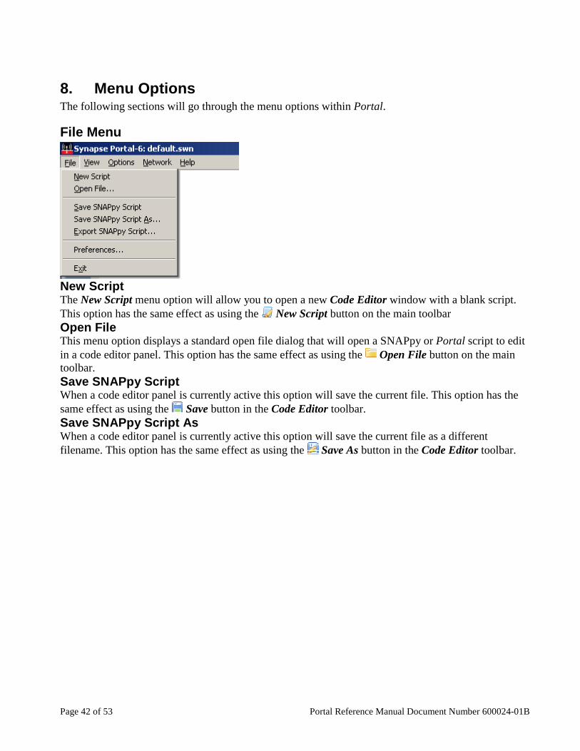
File Menu
New Script The New Script menu option will allow you to open a new Code Editor window with a blank script. This option has the same effect as using the New Script button on the main toolbar Open File This menu option displays a standard open file dialog that will open a SNAPpy or Portal script to edit in a code editor panel. This option has the same effect as using the Open File button on the main toolbar. Save SNAPpy Script When a code editor panel is currently active this option will save the current file. This option has the same effect as using the Save button in the Code Editor toolbar. Save SNAPpy Script As When a code editor panel is currently active this option will save the current file as a different filename. This option has the same effect as using the Save As button in the Code Editor toolbar.
Portal Reference Manual Document Number 600024-01B Page 43 of 53
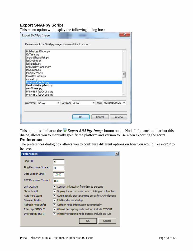
Export SNAPpy Script This menu option will display the following dialog box:
This option is similar to the Export SNAPpy Image button on the Node Info panel toolbar but this dialog allows you to manually specify the platform and version to use when exporting the script. Preferences The preferences dialog box allows you to configure different options on how you would like Portal to behave:

Page 44 of 53 Portal Reference Manual Document Number 600024-01B
The following table describes each option in the Preferences dialog: Ping TTL The Time to Live (TTL) value to use when Portal sends a broadcast ping
request. TTL is sometimes referred to as hops. Ping Response Spread The time in seconds to request nodes to randomize their broadcast ping
responses across. Data Logger Limit The number of data log entries to keep before dropping the oldest entry. RPC Response Timeout
When Portal sends an RPC command to a node for which it expects a response (such as a callout, or a ping to the node), this parameter specifies how long, in milliseconds, Portal will wait for the response before sending the next packet. If your network requires many hops to reach all your nodes, you may want to lengthen this from the default value of 800.
Link Quality Where applicable display link quality as a percentage instead of dBm. Show Result When a function is clicked in the Node Info function tree, request that the
node send the return value of that function to Portal’s event log. Auto Port Scan At startup have Portal automatically start scanning for SNAP bridge nodes. Discover Nodes Automatically have Portal send a broadcast ping at startup. This does not
prevent Portal from discovering who the bridge node is. Refresh Node Info When Portal receives a message from a node not previously heard from, this
option automatically retrieves the node’s information. When administering a large SNAP network, you may want to turn this off to reduce traffic.
Intercept STDOUT When you select a node and use the Intercept STDOUT function, any messages that a node would normally output through a print statement are redirected to the Portal log instead. If you have both this checkbox and the Intercept ERROR checkbox unchecked, the Intercept STDOUT function does not do anything.
Intercept ERROR When you select a node and use the Intercept STDOUT function, any error messages generated by SNAP in the node redirected to the Portal log instead.3 If you have both this checkbox and the Intercept STDOUT checkbox unchecked, the Intercept STDOUT function does not do anything.
Exit This menu option closes Portal, prompting to save any open and unsaved scripts first.
3 In nodes with firmware older than release 2.4, error messages are included in STDOUT automatically, and this option has no effect.
Portal Reference Manual Document Number 600024-01B Page 45 of 53
View Menu
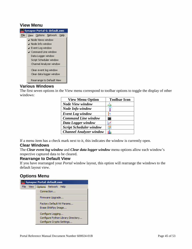
Various Windows The first seven options in the View menu correspond to toolbar options to toggle the display of other windows:
View Menu Option Toolbar Icon Node View window Node Info window Event Log window Command Line window Data Logger window Script Scheduler window Channel Analyzer window
If a menu item has a check mark next to it, this indicates the window is currently open. Clear Windows The Clear event log window and Clear data logger window menu options allow each window’s respective captured data to be cleared. Rearrange to Default View If you have rearranged your Portal window layout, this option will rearrange the windows to the default layout view.
Options Menu
Page 46 of 53 Portal Reference Manual Document Number 600024-01B
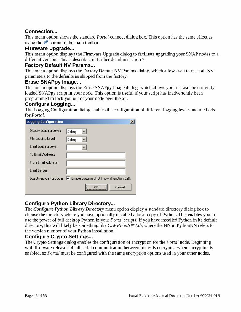
Connection... This menu option shows the standard Portal connect dialog box. This option has the same effect as using the button in the main toolbar. Firmware Upgrade... This menu option displays the Firmware Upgrade dialog to facilitate upgrading your SNAP nodes to a different version. This is described in further detail in section 7. Factory Default NV Params... This menu option displays the Factory Default NV Params dialog, which allows you to reset all NV parameters to the defaults as shipped from the factory. Erase SNAPpy Image... This menu option displays the Erase SNAPpy Image dialog, which allows you to erase the currently loaded SNAPpy script in your node. This option is useful if your script has inadvertently been programmed to lock you out of your node over the air. Configure Logging... The Logging Configuration dialog enables the configuration of different logging levels and methods for Portal.
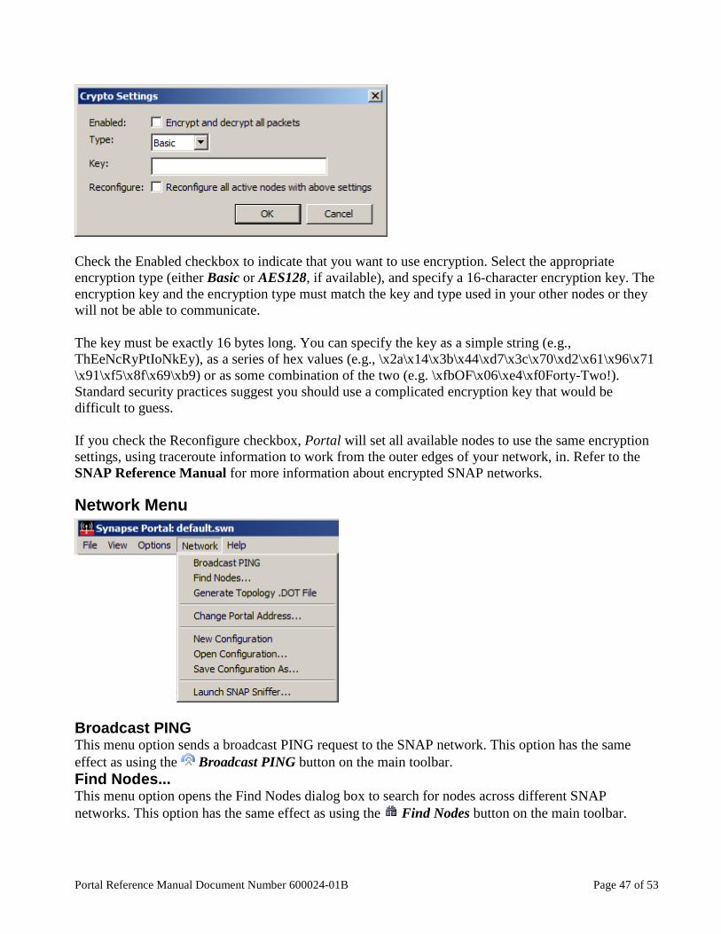
Configure Python Library Directory... The Configure Python Library Directory menu option display a standard directory dialog box to choose the directory where you have optionally installed a local copy of Python. This enables you to use the power of full desktop Python in your Portal scripts. If you have installed Python in its default directory, this will likely be something like C:\PythonNN\Lib, where the NN in PythonNN refers to the version number of your Python installation. Configure Crypto Settings... The Crypto Settings dialog enables the configuration of encryption for the Portal node. Beginning with firmware release 2.4, all serial communication between nodes is encrypted when encryption is enabled, so Portal must be configured with the same encryption options used in your other nodes.
Portal Reference Manual Document Number 600024-01B Page 47 of 53
Check the Enabled checkbox to indicate that you want to use encryption. Select the appropriate encryption type (either Basic or AES128, if available), and specify a 16-character encryption key. The encryption key and the encryption type must match the key and type used in your other nodes or they will not be able to communicate. The key must be exactly 16 bytes long. You can specify the key as a simple string (e.g., ThEeNcRyPtIoNkEy), as a series of hex values (e.g., \x2a\x14\x3b\x44\xd7\x3c\x70\xd2\x61\x96\x71 \x91\xf5\x8f\x69\xb9) or as some combination of the two (e.g. \xfbOF\x06\xe4\xf0Forty-Two!). Standard security practices suggest you should use a complicated encryption key that would be difficult to guess. If you check the Reconfigure checkbox, Portal will set all available nodes to use the same encryption settings, using traceroute information to work from the outer edges of your network, in. Refer to the SNAP Reference Manual for more information about encrypted SNAP networks.
Network Menu
Broadcast PING This menu option sends a broadcast PING request to the SNAP network. This option has the same effect as using the Broadcast PING button on the main toolbar. Find Nodes... This menu option opens the Find Nodes dialog box to search for nodes across different SNAP networks. This option has the same effect as using the Find Nodes button on the main toolbar.

Page 48 of 53 Portal Reference Manual Document Number 600024-01B
Generate Topology .DOT File This option generates a topology.dot file to view a snapshot of your SNAP mesh network. This is accomplished by having the SNAP nodes query for any nodes that are one hop away and report that information for Portal. To view the .DOT file, which is saved in your Portal documents directory, you will need to use a .DOT file viewer. There are several freely available viewers on the internet. Change Portal Address... This option changes the network address of your Portal node. This may be necessary if you have an environment with multiple computers running Portal where the nodes can interact. If more than one Portal node has the same network address (the default is 00.00.01), you can have unpredictable results when nodes attempt to communicate with Portal. The valid network addresses for Portal range from 00.00.01 through 00.00.0F. It is not necessary to restart Portal for this change to take effect. New Configuration This option creates a new Portal configuration, which deletes any locally saved Portal information. Your window layout and all your preferences will be preserved, however scheduled scripts and saved node information will be deleted. For example all the nodes in the Node Views will be deleted and a broadcast ping will be preformed to rediscover the network. Open Configuration... This option opens a previously saved Synapse Wireless Network (.SWN) file that contains saved information about nodes. Save Configuration As... This option saves a Synapse Wireless Network (.SWN) file that contains information about your nodes. Launch SNAP Sniffer... The SNAP Sniffer is an external program that helps to analyze and debug your SNAP network. Please consult the SNAP Sniffer Users Guide for detailed information.
Help Menu
Portal Reference Manual This option will open the Portal Reference Manual (this document) in your default PDF viewer. EK2100 Users Guide This option will open the EK2100 Users Guide in your default PDF viewer.
Portal Reference Manual Document Number 600024-01B Page 49 of 53
EK2500 Users Guide This option will open the EK2500 Users Guide in your default PDF viewer. SNAP Reference Manual This option will open the SNAP Reference Manual in your default PDF viewer. SNAP Sniffer Users Guide This option will open the SNAP Sniffer Users Guide in your default PDF viewer. SNAP Support Forums This option will open the Synapse Support Forums website in your default web browser. This website is the preferred place to ask any technical questions you may have while using our products. About The about dialog displays information about the current version of Portal you are running.
Page 50 of 53 Portal Reference Manual Document Number 600024-01B
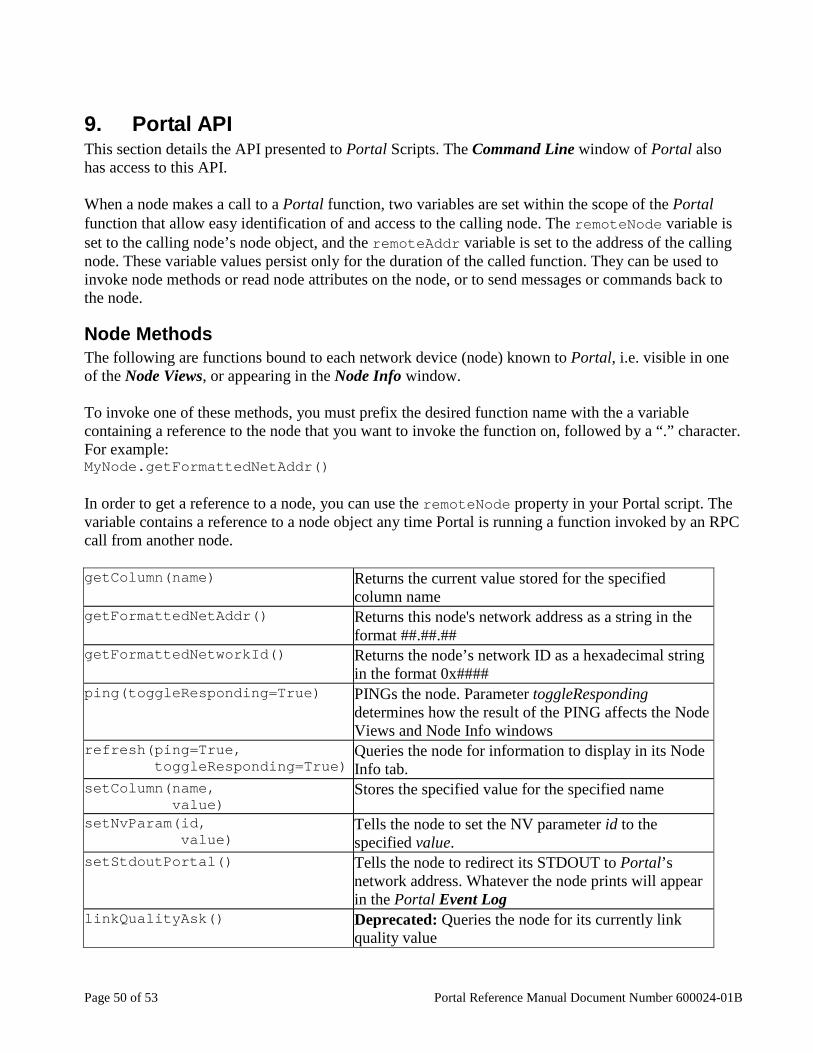
9. Portal API This section details the API presented to Portal Scripts. The Command Line window of Portal also has access to this API. When a node makes a call to a Portal function, two variables are set within the scope of the Portal function that allow easy identification of and access to the calling node. The remoteNode variable is set to the calling node’s node object, and the remoteAddr variable is set to the address of the calling node. These variable values persist only for the duration of the called function. They can be used to invoke node methods or read node attributes on the node, or to send messages or commands back to the node.
Node Methods The following are functions bound to each network device (node) known to Portal, i.e. visible in one of the Node Views, or appearing in the Node Info window. To invoke one of these methods, you must prefix the desired function name with the a variable containing a reference to the node that you want to invoke the function on, followed by a “.” character. For example: MyNode.getFormattedNetAddr() In order to get a reference to a node, you can use the remoteNode property in your Portal script. The variable contains a reference to a node object any time Portal is running a function invoked by an RPC call from another node. getColumn( name) Returns the current value stored for the specified
column name getFormattedNetAddr() Returns this node's network address as a string in the
format ##.##.## getFormattedNetworkId() Returns the node’s network ID as a hexadecimal string
in the format 0x#### ping( toggleResponding =True) PINGs the node. Parameter toggleResponding
determines how the result of the PING affects the Node Views and Node Info windows
refresh( ping =True, toggleResponding =True)
Queries the node for information to display in its Node Info tab.
setColumn( name, value )
Stores the specified value for the specified name
setNvParam( id , value )
Tells the node to set the NV parameter id to the specified value.
setStdoutPortal() Tells the node to redirect its STDOUT to Portal’s network address. Whatever the node prints will appear in the Portal Event Log
linkQualityAsk() Deprecated: Queries the node for its currently link quality value
Portal Reference Manual Document Number 600024-01B Page 51 of 53
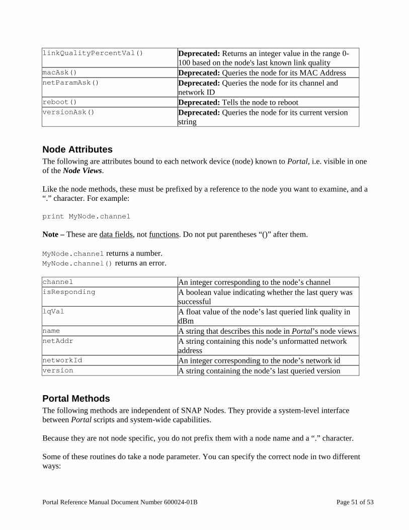
linkQualityPercentVal() Deprecated: Returns an integer value in the range 0-100 based on the node's last known link quality
macAsk() Deprecated: Queries the node for its MAC Address netParamAsk() Deprecated: Queries the node for its channel and
network ID reboot() Deprecated: Tells the node to reboot versionAsk() Deprecated: Queries the node for its current version
string
Node Attributes The following are attributes bound to each network device (node) known to Portal, i.e. visible in one of the Node Views. Like the node methods, these must be prefixed by a reference to the node you want to examine, and a “.” character. For example: print MyNode.channel Note – These are data fields, not functions. Do not put parentheses “()” after them. MyNode.channel returns a number. MyNode.channel() returns an error. channel An integer corresponding to the node’s channel isResponding A boolean value indicating whether the last query was
successful lqVal A float value of the node’s last queried link quality in
dBm name A string that describes this node in Portal’s node views netAddr A string containing this node’s unformatted network
address networkId An integer corresponding to the node’s network id version A string containing the node’s last queried version
Portal Methods The following methods are independent of SNAP Nodes. They provide a system-level interface between Portal scripts and system-wide capabilities. Because they are not node specific, you do not prefix them with a node name and a “.” character. Some of these routines do take a node parameter. You can specify the correct node in two different ways:

Page 52 of 53 Portal Reference Manual Document Number 600024-01B
• By explicit address • By node name (the node’s name within Portal)
Explicit addresses are three-byte strings. Portal shows node Network Addresses in hexadecimal, but omits any number base prefixes or suffixes. If Portal shows a node’s Network Address as 12.34.56, then the individual address bytes are 0x12, 0x34, and 0x56 (hexadecimal), not 12, 34, and 56 (decimal). To specify hexadecimal constants within Python or SNAPpy strings, you use a leading “\x”. Going back to our example, if you want to specify the node with address 12.34.56, you would use “\x12\x34\x56” in your script. Portal also assigns names to nodes when it first discovers them. If the node with address 12.34.56 has a displayed name of “MyNode” then instead of specifying an explicit address string, you can just use the text MyNode instead. Note – There are no quotation marks used when referencing nodes by name within Portal scripts (or from the Portal command line). So, assuming node MyNode4 is at address AB.CD.EF, the following two commands are equivalent: sendData("\xAB\xCD\xEF", "This is a test") sendData(MyNode4, "This is a test") logEvent( message ) Log the specified message to the Event Log logData( name, value , fullscale =100.0)
Plot the specified value to a named strip chart in the Data Logger window
mcastRpc( groups, ttl, function, *args )
Sends a multicast RPC request to the specified groups. Parameter function is the routine to invoke on each node in the specified groups, and the remaining parameters are passed to that routine.
multicastRpc( …) The same as the mcastRpc function above but left for backwards compatibility with older version of Portal
rpc( node , function , * args )
Sends an RPC request to the specified node. Parameter function is the routine to invoke on the node, and the remaining parameters are passed to that routine.
sendDataModePkt( node , data )
Sends data to the specified node in a way that mimics TRANSPARENT MODE. This lets Portal insert data into TRANSPARENT MODE links.
sendEmail( recipients , sender , msg, server )
Sends an e-mail containing msg text to the specified recipients via the specified (e-mail) server, addressed as if it came from sender.
sendMcastDataModePkt( group, ttl, data )
Sends data to the specified multicast group in a way that mimics TRANSPARENT MODE. This lets Portal insert data into TRANSPARENT MODE links.

Portal Reference Manual Document Number 600024-01B Page 53 of 53
sendTraceRouteRequest( node, sequence )
Sends a traceroute request packet to the specified node with the specified sequence number
There are also some commands that must be prefixed by “root.” root.clearEventLog() Clears the Portal Event Log root.displayTraceFile() Pops up a tabbed window with the contents of an
internal log file sometimes used in debugging. root.sendDataModePkt( node , data )
This is the same as the standalone function sendData() , use sendData() instead
root.setPortalNetAddr( newAddr ) Change Portal’s network address from the default value of “\x00\x00\x01” (00.00.01). Portal’s network address can range from \x00\x00\x01 to \x00\x00\x0F.
There are several commands that are deprecated or for Synapse internal use only. They are listed here only for completeness; you should not be calling these functions. cmdDispatcher Synapse use only notifyOnComplete() Synapse use only setup_usb_as_vcp() Synapse use only setupSynapseUsb() Synapse use only snappyErrorDecode( node, errorMsg )
Synapse use only